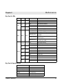
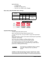
1
User Guide Digi One IA Digi One SP 92000326_D Digi International Inc. 2003. Digi, Digi International, the Digi logo, the Digi Connectware, the Making Device Networking Easy logo, Digi One, and RealPort are trademarks or registered trademarks of Digi International, Inc. in the United States and other countries worldwide. All other trademarks are the property of their respective owners. 92000326_D Contents Chapter 1 Introduction Introducing the Digi One IA ................................................................... 7 Digi One IA Overview ................................................................................ 7 Digi One IA Key Features .......................................................................... 8 Introducing the Digi One SP .................................................................. 8 Digi One SP Overview ............................................................................... 8 Digi One SP Key Features.......................................................................... 9 Chapter 2 Configuring the IP Address IP Address Configuration Methods......................................................11 Configuring the IP Address with the Setup Wizard.............................. 11 Prerequisites ............................................................................................. 11 Procedure ................................................................................................. 12 Configuring the IP Address with DHCP ............................................... 12 Prerequisite............................................................................................... 12 Procedure ................................................................................................. 12 Configuring an IP Address with ARP-Ping .......................................... 12 Prerequisites ............................................................................................. 12 Procedure ................................................................................................. 12 Example .................................................................................................... 13 Testing the IP Address Configuration.................................................. 13 Prerequisite............................................................................................... 13 Procedure ................................................................................................. 13 Example .................................................................................................... 13 Changing an IP Address from a Web Browser.................................... 13 Prerequisite............................................................................................... 13 Procedure ................................................................................................. 13 Chapter 3 Setting Up RealPort (COM Port Redirection) What is RealPort..................................................................................15 RealPort Setup Overview ....................................................................15 Configuring the Device Server for RealPort ....................................... 16 Installing RealPort on a System Running Microsoft Windows Operating System from the CD ............................................................................ 16 Installing RealPort on a Windows System from the Web .................... 16 Contents 3 Chapter 4 Using the Web Interface Introduction.......................................................................................... 19 Getting Started .................................................................................... 19 Network Settings ................................................................................. 20 Serial Port Settings.............................................................................. 20 Basic Serial Settings ................................................................................. 21 Advanced Serial Settings.......................................................................... 21 Security................................................................................................22 System................................................................................................. 22 Administration...................................................................................... 22 Chapter 5 Configuring Advanced Functions Port Profiles ......................................................................................... 23 RealPort Profile......................................................................................... 23 TCP Sockets Profile.................................................................................. 24 UDP Sockets Profile ................................................................................. 24 Serial Bridging Profile ............................................................................... 25 Printer Profile ............................................................................................ 26 Terminal Profile......................................................................................... 26 Custom Profile .......................................................................................... 26 Chapter 6 Administration Changing the Root Password.............................................................. 27 Prerequisite............................................................................................... 27 Procedure ................................................................................................. 27 Updating Firmware .............................................................................. 27 Prerequisite............................................................................................... 27 Procedure for Updating from a File on Your PC ....................................... 28 Procedure for TFTP .................................................................................. 28 Updating POST Code.......................................................................... 28 Prerequisite............................................................................................... 28 Procedure ................................................................................................. 28 Restoring the Configuration to Factory Defaults.................................. 29 Introduction ............................................................................................... 29 Resetting the Configuration from a Browser ............................................. 29 Resetting the Configuration Using the Reset Button ................................ 30 Backup/Restore the Configuration....................................................... 30 Prerequisite............................................................................................... 30 Procedure ................................................................................................. 31 Viewing Port or Network Statistics and Settings.................................. 31 Introduction ............................................................................................... 31 Procedure ................................................................................................. 31 4 Contents Chapter 7 Troubleshooting Before contacting Tech Support, check the following:......................... 33 Introduction ............................................................................................... 33 Hardware .................................................................................................. 33 Power........................................................................................................ 33 Ethernet Cable .......................................................................................... 33 EIA 232/422/485 Switches........................................................................ 34 IP Address ................................................................................................ 34 Cabling...................................................................................................... 35 Software - RealPort .................................................................................. 35 Firmware ................................................................................................... 36 Chapter 8 Reference Digi One IA LEDs ................................................................................ 37 Digi One IA Specifications ................................................................... 37 DB9 and Screw Terminal Pinouts........................................................ 38 FCC Class A Statement: Digi One IA .................................................. 38 Digi One IA Emissions .............................................................................. 38 Digi One IA Immunity ................................................................................ 38 Digi One IA Safety .................................................................................... 38 Digi One SP LEDs ............................................................................... 39 Digi One SP Specifications.................................................................. 39 FCC Class A Statement: Digi One SP................................................. 39 Digi One SP Emissions............................................................................. 39 Digi One SP Immunity .............................................................................. 39 Digi One SP Safety ................................................................................... 40 Device Server EIA 232/422/485 Switch Settings................................. 40 Important Safety Information ............................................................... 40 Digi Contact Information ...................................................................... 41 Index......................................................................................................... 43 Contents 5 6 Contents Introduction Chapter 1 Introducing the Digi One IA Digi One IA Overview The Digi One IA device server easily enables any industrial device with a serial port to connect to the Ethernet. These devices include Programmable Logic Controllers, process and quality equipment, motors, drives, bar-code readers, operator displays, and other types of manufacturing equipment. DIG IO NE IA The Digi One IA delivers cost-effective performance and capability in a rugged DIN Rail mountable enclosure specifically designed for the Industrial Automation market. Part of Digi’s broad device server offering, the Digi One IA delivers standard Serial-to-Ethernet connectivity and is ideal for the following applications: • TCP socket and UDP socket Socket support includes serial bridging, which requires two device servers, each providing network connectivity for a serial device that would otherwise be limited to communication over a serial cable. • RealPort (COM Port Redirection using Digi’s patented RealPort software) Enables applications and serial devices to communicate over an Ethernet network as though they were communicating in their native serial mode over a cable. The Digi One IA is easy to install locally or remotely through a variety of IP addressing methods. These include DHCP, ARP-Ping, static IP, and Setup, an application included on the installation CD that automatically detects all Digi One devices on your network. Chapter 1 Introduction 7 Digi One IA Key Features Here are some key Digi One IA features: • TCP/UDP socket services for broad device connectivity and application use • Support for RFC 2217 • RealPort (COM Port Redirection) • DB9M and screw terminals for serial port connection • Galvanically isolated (from earth ground) • Class 1, Div2 rated • Industry leading low latency • EIA-232/422/485 switch selectable • Easy configuration using the install CD through Setup wizard, web interface, or command line Introducing the Digi One SP Digi One SP Overview The Digi One SP device server easily allows any device with a serial port to connect to the Ethernet. The compact Digi One SP delivers cost-effective performance and capability in one of the smallest form factors available. DIG 8 IO NE SP Chapter 1 Introduction Part of Digi’s broad device server offering, the Digi One SP delivers standard Serial-to-Ethernet connectivity and is ideal for the following applications: • TCP socket and UDP socket Socket support includes serial bridging, which requires two device servers, each providing network connectivity for a serial device that would otherwise be limited to communication over a serial cable. • COM Port Redirection using Digi’s patented RealPort software, which enables applications and serial devices to communicate over an Ethernet network as though they were communicating in their native serial mode over a cable. The Digi One SP is easy to install locally or remotely through a variety of IP addressing methods. These include DHCP, ARP-Ping, static IP, and Setup, an application on the installation CD that automatically detects all Digi One devices on your network. Digi One SP Key Features Here are some key Digi One SP features: • TCP/UDP socket services for broad device connectivity and application use Chapter 1 • Support for RFC 2217 • RealPort (COM Port Redirection) • DB9M for serial port connection • Galvanically isolated (from earth ground) • Industry leading low latency • EIA-232/422/485 switch selectable • Easy configuration using the install CD through Setup wizard, web interface, or command line Introduction 9 10 Chapter 1 Introduction Configuring the IP Address Chapter 2 IP Address Configuration Methods An IP address can be assigned to the device server using any of the following methods: • • • • • Setup Wizard “Discovers” the device and then provides a method for assigning an IP address. See "Configuring the IP Address with the Setup Wizard" on page 11. DHCP The device server’s default configuration is as a DHCP client. See "Configuring the IP Address with DHCP" on page 12. ARP-Ping Enables IP address assignment by updating the ARP tables on a PC with the device server’s MAC address and then pinging the device server. See "Configuring an IP Address with ARP-Ping" on page 12. Web browser This method works only for changing the IP address of a device server that has already been assigned an IP address. Command Line Use the Command Reference from the Digi support site: http://support.digi.com/support/manuals/index.html. Select your device and Command Reference. Before you configure your device server, write down the MAC Address located on the bottom of your product. Configuring the IP Address with the Setup Wizard This procedure describes how to configure an IP address using the CD that came in your device server package. Prerequisites This procedure assumes the following: • The device server is connected to the network and powered up Chapter 2 Configuring the IP Address 11 • • The CD will be used on a system running Microsoft Windows operating system or a Unix operating system The device server’s MAC address is recorded for later use in assigning an IP address Procedure 1. Insert the Digi CD in the CD drive. 2. If the CD does not start automatically, double-click My Computer > CD ROM Drive > setup.exe 3. The wizard will automatically pop up. Click Next. The Digi application finds and lists all of the Digi devices on your network. 4. Locate your device server by its MAC address. 5. Select the device server and then click Next. 6. Follow the wizard to configure your device server. Configuring the IP Address with DHCP Prerequisite This procedure assumes the following: • That the device server is configured as a DHCP client. Since this is the default configuration, this will be the case unless the configuration has been changed. • That the device server is not powered on Procedure 1. Set up a permanent entry for the device server on a DHCP server. 2. Connect the device server to the network and power it on. The IP address configured in step 1 is assigned automatically. Configuring an IP Address with ARP-Ping Prerequisites This procedure assumes the following: • That the device server is connected to the network and powered up • That you have access to a PC on the same LAN as the device server • No DHCP server is running • No IP address has been configured Procedure Manually update the PC’s ARP (Address Resolution Protocol) table using the device server’s MAC address (on the bottom of the unit) and the IP address you want assigned to the device server. Here is how this is done on a system running Microsoft Windows operating system: 12 Chapter 2 Configuring the IP Address 1. Access the command line. 2. Issue the following command: arp -s ip-address mac-address Example arp -s 192.168.2.2 00-40-9D-00-00-00 Ping the Digi device using the IP address just assigned. ping 192.168.2.2 The ping will probably time out before there is a response from the device server. Wait a few seconds and then ping the device server again. The device server will respond indicating that the IP address has been configured. Testing the IP Address Configuration Use this procedure to test your IP address configuration. Prerequisite This procedure assumes that you have configured the device server with an IP address. Procedure 1. Access the command line of a PC or other networked device. 2. Issue the following command: ping ip-address where ip-address is the address you assigned to the device server. Example ping 192.168.2.2 A reply should be returned. Changing an IP Address from a Web Browser Prerequisite This procedure assumes that the device server already has an IP address and you simply want to change it. Procedure 1. Open a web browser and enter the device server’s current IP address in the URL address bar. 2. When the device server prompts you to log on, specify the following: • The username is root. • The default password is dbps. 3. Click Network to access the Network Configuration page. 4. Enter an IP address (and other network-related parameters) and then click Apply to save the configuration. Chapter 2 Configuring the IP Address 13 14 Chapter 2 Configuring the IP Address Chapter 3 Setting Up RealPort (COM Port Redirection) What is RealPort Many serial devices, including barcode scanners and sensors, don’t have an Ethernet port. And even if they did, the applications that run them work on COM1. They know nothing of networking or TCP/IP. Many of these applications were written before TCP/IP and Internet were common. RealPort allows you to really network enable your device with our device servers. With a Digi device server, you can easily connect your device to the network. The legacy application, however, may not support TCP/IP. That’s where RealPort comes in. Installed on a network-based PC, RealPort emulates a serial port. That is, the application “thinks” it is working with a real serial port, such as COM1. When the application sends data to this serial port, RealPort ships the data across the network to the device server which in turn routes it to the serial device. This is also referred to as COM Port Redirection. The network is transparent to both the application and the device. In the example that follows, the RSLogix software and the PLC communicate as though they were connected with a serial cable. DIG IO NE IA IGI NE IA RealPort Setup Overview To set up a RealPort configuration, complete the following tasks: 1. Configure the device server for RealPort. See "Configuring the Device Server for RealPort" on page 16. Chapter 3 Setting Up RealPort (COM Port Redirection) 15 2. Install the RealPort software on your PC. See "Installing RealPort on a System Running Microsoft Windows Operating System from the CD" on page 16. For UNIX RealPort software and documentation, see the Digi web site (www.digi.com). Configuring the Device Server for RealPort 1. Access the configuration by opening a web browser and entering the IP address in the URL address bar. 2. Log on as the root user (User Name root). The default password is dbps. 3. If this is not a new device server, restore the default settings by clicking Administration. Note: Restoring the Digi One device to its factory default settings will clear all current settings except the IP address settings and the administrator password. 4. Select Restore Factory Default Settings and click Restore. 5. Click Serial Port > Change Profile 6. Select RealPort and click Apply. Note: No other serial communication settings are required. 7. Load RealPort driver. See "Installing RealPort on a System Running Microsoft Windows Operating System from the CD" on page 16 Installing RealPort on a System Running Microsoft Windows Operating System from the CD Use this procedure to install RealPort software. Note: It is recommended that you check the Digi website for the latest RealPort drivers. 1. Place the CD in the CD drive. 2. If the CD does not start automatically, click Start > Run and in the run dialog, browse to the root of the CD and then click setup.exe. 3. Click Cancel on the wizard (this will close the Setup wizard). 4. Click Install Optional Software. 5. Click RealPort. 6. Follow the on-screen prompts and use the Microsoft Windows Help for assistance. Note: See the Digi website for UNIX RealPort drivers and documentation. Installing RealPort on a Windows System from the Web 1. Go to www.digi.com 2. Click Support. 16 Chapter 3 Setting Up RealPort (COM Port Redirection) 3. 4. 5. 6. 7. Chapter 3 Click Drivers. Select your product. Select your operating system. Click Latest Driver. Download the driver and follow the ‘readme’ for download instructions. Setting Up RealPort (COM Port Redirection) 17 18 Chapter 3 Setting Up RealPort (COM Port Redirection) Using the Web Interface Chapter 4 Introduction This section describes the web interface that may be used to configure the device server. The interface is recommended for use if the wizard is unavailable or your application requires specific alterations not accessible on the wizard. Getting Started The wizard from the CD is designed to successfully configure the Digi device server. However, if you need to alter your configuration, or you do not have the CD, use the web interface to access your device server. Enter the IP address in the URL address bar of your browser. Enter the User Name root and default Password dbps . dbps After you log on, you will see this screen: 192.168.2.2 Chapter 4 Using the Web Interface 19 Network Settings Network settings allow you to change the IP address. Advanced Network Settings allow you alter the Ethernet Interface speed and mode, TCP/IP settings, TCP keepalive settings, or DHCP settings. The screen below is the Advanced Network page. Use this page to adjust Ethernet Speed, Ethernet Mode, TCP Time-ToLive, IP Time-To-Live, Probe Interval, Probe Count, Retransmission Timeout, DHCP Client Identifier, Client Identifier Type, Enable TCP Keepalive, Idle Timeout, Keepalive Byte, and Telnet Break. Serial Port Settings Use the Serial Port link to establish a port profile that will assist you to set up your device. You may also adjust the Basic Serial Settings (baud rate, data bits, parity, stop bits, and flow control). The screen below shows the options under the Port profile. If you select an option the port setting will automatically request the correct information for your profile. Select your profile based on the way you will use your device.For more information about advanced configurations and port profiles see "Configuring Advanced Functions" on page 23. 20 Chapter 4 Using the Web Interface Click Apply to save the profile. Basic Serial Settings After you select your port profile, the profile settings will appear. Click the appropriate features for your environment. The following information is a brief description of the fields within the Basic Serial Settings. The context sensitive Help link in the upper right hand corner can provide additional information. • Description -Specifies an optional character string for the port which can be used to identify the device connected to the port. • Serial Port Settings include Baud Rate, Data Bits, Parity, Stop Bits, and Flow Control -The basic serial port settings must match the serial settings of the connected device. If you do not know these settings consult the documentation that came with your serial device. These serial settings may be documented as 9600 8N1, which means that the device is using a baud rate of 9600 bits per second, 8 data bits, no parity, and 1 stop bit. When using RealPort (COM port redirection) or RFC 2217 these settings are supplied by applications running on the PC or server, and the default values on your Digi device server do not need to be changed. Advanced Serial Settings The advanced serial settings allow you to enable Verbose connection status messages, Force DCD, Binary mode for Telnet, RTS Toggle Predelay, MS Post-delay, Inter-character timeout, Timeout, and Send socket ID string. The following screen illustrates your options. Chapter 4 Using the Web Interface 21 Click Apply to save the settings. Security The Security page allows you to change your password from the default password (username root, password dbps). To increase security for your device, change the password. System The System page allows you enter the Device name, Contact, and Location and change the Optimization from either Latency or Throughput. You can access the SNMP settings from this page as well. Administration Use the Administration section of the web interface to backup or restore your settings, update firmware, reset factory default settings, read system information, reboot, or log out. 22 Chapter 4 Using the Web Interface Configuring Advanced Functions Chapter 5 Port Profiles The web interface allows users to configure a serial port based on the way the port will be used. Each profile displays the relevant settings for the configuration. There are 7 profile choices with Custom allowing the user to view all settings. 1. To configure any profile select Serial Ports 2. Click the port to be configured. 3. Click Change Profile 4. Select any profile and Click Apply. 5. Enter the appropriate parameters for each profile and click Apply to save the settings. RealPort Profile The RealPort Profile allows you to configure your device to create a virtual COM port on your PC. This is also known as COM Port Redirection. The PC applications send data to this virtual COM port and RealPort sends the data across the network to the Digi device server. The data is routed to the serial device connected to the Digi device server’s serial port. The network is transparent to both the application and the serial device. Note: RealPort software (from the Software and Documentation CD) must be installed and configured on each PC that will use RealPort ports. Enter the IP address of the Digi device server and the RealPort TCP port number 771. See "Setting Up RealPort (COM Port Redirection)" on page 15 for more information. Chapter 5 Configuring Advanced Functions 23 TCP Sockets Profile This profile allows serial devices to communicate over a TCP network. The TCP Server allows other network devices to initiate a TCP connection to the serial device attached to the serial port of the Digi device server. The TCP Client allows the Digi device server to automatically establish a TCP connection to an application or a network. Note: If using the RFC 2217 protocol, do not modify the port settings from the defaults. Note: RFC 2217 Support Digi device servers support RFC 2217, an extension of the Telnet protocol used to access serial devices over the network. RFC 2217 implementations enable applications to set the parameters of remote serial ports (baud rate, flow control, etc.), detect line signal changes, as well as receive and transmit data. The configuration information provided in this section applies to device servers functioning as RFC 2217 servers. If you have altered the device server, restore the factory default settings following the procedure in Chapter 3. No additional configuration is required. UDP Sockets Profile This profile allows serial devices to communicate using UDP. The UDP Server configuration allows the serial port to receive data from one or more systems or devices on the network. The UDP Client configuration allows the automatic distribution of serial data from one host to many devices at the same time using UDP sockets. This is also referred to as UDP Multicast. 24 Chapter 5 Configuring Advanced Functions Note: About TCP and UDP Port Numbers Digi device servers use the TCP and UDP port numbering conventions described in the following table: For this connection type... Use this Port Telnet to the serial port 2001 (TCP only) Raw connection to the serial port 2101(TCP and UDP) You must ensure that the application or device that initiates communication with the device server uses these ports. If they cannot be configured to use these ports, you can change what is known as the “base socket” on the device server, which allows you to use different port numbers to designate a Telnet or raw connection to the serial port. See "Changing the Base Socket: Procedure" on page 25 for more information. Changing the Base Socket: Procedure 1. Access the configuration by opening a web browser and entering the device server’s IP address in the URL window. 2. Log on to the device server as the root user (User Name root). The default root password is dbps. 3. From the main menu, click Network. 4. Use the base socket field to change the base socket. Specify any number between 1899 and 50000. Telnet connections will use the base socket value plus one. Raw connections will use the base socket value plus 101 (one-hundred one). The following table illustrates how this works: If the base socket is... Then Telnet uses... Then Raw uses... 3000 3001 3101 4151 4152 4252 8025 8026 8126 6. Click Apply. Serial Bridging Profile This profile allows users to create a serial bridge. A serial bridge is a network connection between two serial devices, each of which uses a device server. The serial devices “think” they are communicating with each other across a serial cable using serial communication techniques. There is no need to reconfigure the server or the serial device. Neither is aware of the intervening network. This profile configures each side of the bridge separately. Repeat the configuration for the second Digi device server of the bridge specifying the IP address of the first Digi device server. Chapter 5 Configuring Advanced Functions 25 Printer Profile This profile allows you to connect a printer to a serial port. Use this profile if you intend to print using the lpd protocol on your UNIX system. Note: Refer to your UNIX User Guide for tips on configuring the print spooler on your UNIX system. Terminal Profile This profile allows you to connect to a terminal to the serial port. Custom Profile This profile allows you to see all settings and set them accordingly. Use this profile only if your application does not fit into any of the predefined port profiles. 26 Chapter 5 Configuring Advanced Functions Administration Chapter 6 Changing the Root Password For security reasons, we recommend you change the root password immediately. This procedure shows you how. Prerequisite This procedure assumes that you are the root user and that you know the current root password. Procedure 1. Open a web browser and enter the device server’s IP address in the URL window. 2. When the device server prompts you to log in, enter the following: • User Name is root • The root default password is dbps 3. Click Security. 4. Fill in the New Password and Confirm Password fields. 5. Click Apply to save the password. 6. Log on using new password (you will receive notification password is changed). Updating Firmware This procedure shows you how to update the device servers firmware from a file on your PC or through TFTP. Note: The recommended method is to download the firmware to your local hard drive. TFTP is supported for those using UNIX systems. Prerequisite This procedure assumes that: • You have already downloaded the firmware file from the Digi web site • TFTP is running (if you are using the TFTP option) Chapter 6 Administration 27 Procedure for Updating from a File on Your PC DO NOT close your browser until the update is complete and you have been prompted to reboot 1. Open a web browser and enter the device server’s IP address in the URL window. 2. When the device server prompts you to log in, enter the following: • User Name is root • The root default password is dbps 3. Click Upgrade Firmware from the main menu. 4. Select Firmware. 5. Click Browse to select the file. 6. Click Update. Procedure for TFTP 1. Open a web browser and enter the device server’s IP address in the URL window. 2. When the device server prompts you to log in, enter the following: • User Name is root • The root default password is dbps 3. Click Upgrade Firmware from the main menu. 4. Click From a TFTP Server. 5. Select Firmware. 6. Enter the name of the firmware file. 7. Enter the IP address of the TFTP server where firmware file is located. 8. Click Update. Updating POST Code This procedure shows you how to upgrade POST code from a file or TFTP. Typically, POST upgrades are not required and should only be done if the firmware release notes indicate that this step is required. Note: The recommended method is to download the firmware to your local hard drive. TFTP is supported for those using UNIX systems. Prerequisite This procedure assumes that: • You have already downloaded the firmware file from the Digi web site • TFTP is running (if you are using the TFTP option) Procedure 1. Open a web browser and enter the device server’s IP address in the URL window. 2. When the device server prompts you to log in, enter the following: • User Name is root • The root default password is dbps 28 Chapter 6 Administration 3. Click Update Firmware. A screen appears with the options to update from a file or with a TFTP server. 4. Choose either: From a File • • • Select Boot/POST from the Update dropdown menu. Browse to locate the file. Click Update. From a TFTP Server • • • • Select Boot/POST from the Update dropdown menu. Enter the Firmware Image File name. Enter the TFTP Server’s IP. Click Update. Restoring the Configuration to Factory Defaults Introduction The two procedures in this section restore the configuration to defaults. The first procedure resets the configuration from a web browser which will clear all current settings except the IP address settings and administrator password. This is the best way to reset the configuration because you can also back up the settings (which provides a means for restoring it after you have worked through configuration issues). See "Backup/Restore the Configuration" on page 30 for more information. The second procedure resets the configuration using the reset button on the device server. Use this method if you cannot access the device from a web browser. Note: Restoring the Digi One device to its factory default settings will clear all current settings except the IP address settings and the administrator password. Resetting the Configuration from a Browser 1. Open a web browser and enter the device server’s IP address in the URL window. 2. When the device server prompts you to log on, enter the following: • User Name is root • The root default password is dbps 3. Click Factory Default Settings from the main menu. 4. Click Restore. Chapter 6 Administration 29 Resetting the Configuration Using the Reset Button 1. Power off the device server by unplugging the power. 2. Use a non-conducive, small diameter tool (such as wood or plastic) with a blunt end (NOT SHARP or the button could be damaged) to press gently and hold down the reset button. The flashing sequece of LEDs may take several seconds. The following figures help you locate the reset button. The first shows a Digi One IA. The second a Digi One SP. 3. While holding the reset button, power up the unit. 4. Hold the button for 20 seconds and then release it. The default configuration is restored. Backup/Restore the Configuration This procedure shows you how to backup or restore the configuration to a server and to download a configuration from a server to a file or TFTP. Prerequisite If you intend to use TFTP, ensure that the TFTP program is running on a server before you begin this procedure. 30 Chapter 6 Administration Procedure 1. Open a web browser and enter the device server’s IP address in the URL window. 2. When the device server prompts you to log in, enter the following: • User Name is root • The root default password is dbps 3. Click Backup/Restore from the main menu. 4. Choose the appropriate option (Backup or Restore) and select your file. Viewing Port or Network Statistics and Settings Introduction Use this procedure to view port or network statistics and configuration settings. Procedure 1. Open a web browser and enter the device server’s IP address in the URL window. 2. When the device server prompts you to log in, enter the following: • User Name is root • The root default password is dbps 3. Click Device Information from the main menu. 4. Click Network Protocols, Route Table or Port 1 for specific information. Use your browser’s Refresh option to update the statistics. Chapter 6 Administration 31 32 Chapter 6 Administration Tr o u b l e s h o o t i n g Chapter 7 Before contacting Tech Support, check the following: Introduction Before contacting Tech Support there are several things you can do to identify if the problem is related to hardware, software, or firmware. The following sections will walk you through the basic diagnostic procedures. Hardware The following tests or procedures will help you determine if the problem is related to the hardware. Power Always check the power first. The LED panel on the device server will indicate if the power is detected. The Digi One IA uses a green power light and the Digi One SP uses a red power light. Be sure to use a proper power supply for your device. The Digi One SP comes with its own power supply. Use the table below for the Digi One IA power requirements. Input Voltage Input Current 9V 414mA 10V 333mA 11V 297mA 12V 268mA 13V 244mA 14V 210mA 20V 153mA 25V 125mA 30V 105mA Ethernet Cable When you connect the Ethernet cable, the Digi One IA Red Link LED should go out. If it stays on, the network is not detected. The Digi One SP Green Link LED should stay on. If it goes out, the network is not detected. Check the Ethernet cable for the following: Chapter 7 Troubleshooting 33 • • • • Connected securely at both ends Pinned correctly Quality is sufficient for cable length and environment Ethernet hub is properly configured Refer to the Chapter 8 Reference for more information about LEDs. EIA 232/422/485 Switches Verify the EIA 232/422/485 switches are set to your peripheral device’s requirements. These settings are on the Digi One IA label, the Quick Start guide for the Digi One SP, and the reference section of this guide. However, if you are having trouble logging on to the Digi One IA device and assigning an IP address, set the switches to EIA-232 (1-up; 2, 3, & 4 down). After your initial configuration, change the switches to match your peripheral device’s requirements. Go to Chapter 8 for additional Reference information. IP Address The IP address must be configured on the device server and the Subnet Mask and Gateway must be correct before it can be accessed on the network Verify the Digi device server’s IP address using PING. See Chapter 2 Getting Started page 14 for instructions. If you are unable to PING, you may have a duplicate IP address or the IP is not configured correctly. Go back to Chapter 2 or run the wizard from the CD to set the IP address. If you can PING, you can now verify the connection to the serial port on the device server. Connect the loop back plug (shipped with your device) to the serial port on the device server. Make a connection between the serial port of the device server and your operating system using the following Telnet command: telnet 191.168.2.2 2001 (use the IP address you assigned) Type a unique word or phrase to see if it displays on the screen properly that is every stroke is displayed. Verify that local echo is not on by removing the loop back and type another word or phrase. There should be no display. If the display is correct with the loop back, you have successfully connected to the port and your device server is configured correctly. To disconnect, press Ctrl ] and at the Telnet prompt, type quit. If you are unable to Telnet to the port, make sure you are running the latest firmware release available and the port is configured to accept inbound 34 Chapter 7 Troubleshooting connections. If your device server is configured correctly but you are unable to communicate with your serial device connected to the device server port, check the cabling. Cabling Make sure you have the proper cabling from the Digi One IA (or SP) device server’s serial port to the connecting device. The Digi One is a DTE device. The DB9 pinout can be found on the Digi One IA device label or on the Quick Start Guide for the Digi One SP. If you are using the Screw Terminal Block instead of the DB9 serial port, count pin # 1 as the one farthest from the DB9 serial port. Pinout information is also available in this manual and online at http://support.digi.com. If your cabling is correct, try resetting the device in Chapter 7 Administration, page 46 or 47. Software - RealPort Install RealPort according to the procedure in Chapter 3 pages 19-21. If the IP address is set correctly but you are having trouble with RealPort, verify TCP port 771 is open for the RealPort driver to get to the Digi One device server. Chapter 7 Troubleshooting 35 If HyperTerminal works with the loop back but you cannot communicate with your serial device, check the cabling. Do not leave your browser until you are prompted to reboot. 36 1. Download RealPort from the CD enclosed with the device server or from the Tech Support FTP site. 2. Verify you have the latest version of the driver installed. 3. Open up HyperTerminal and connect to the COM Port you want to test. 4. Plug the DB-9 Loop back (shipped with the product) into the serial port into the Digi device. 5. Type a unique word or phrase to see if it displays on the screen properly - that is every character or keystroke is displayed. Verify that local echo is not on by removing the loopback and typing another word or phrase. There should be no display. If the display is correct with the loopback, you have successfully connected to the port and your device server is configured correctly. If it doesn’t work go to step 6. 6. If you continue to have problems, try to Telnet to the device server serial port (as discussed earlier in this chapter) to verify the hardware setup. Firmware If your hardware is okay, make sure you are running the latest firmware version available. Check the Digi Support site for the latest firmware and/or POST updates for your device: http://ftp.digi.com/support/firmware 1. Download a copy of the firmware file. 2. Access the Digi device server’s web interface by entering the Digi device server’s IP address in a browser’s URL window and log on (User Name root, Password dbps). 3. Click Update Firmware from main menu. 4. Browse to the location on your system where the firmware has been saved, select the correct file, and click Update. 5. Reboot the device when prompted. 6. Access the Digi device server’s web interface and verify on the Information Page that the Firmware version has been successfully updated. Chapter 7 Troubleshooting Reference Chapter 8 Digi One IA LEDs LED Power LAN Diag Color Power Green Link Red TX/RX Green Diag State Indicates On Power detected off No power detected On No network detected Off Network detected On Network traffic Off No network traffic Blinking 1-1-1 Starting the EOS Blinking 1-3-1 Starting the TFTP process Blinking 1-5-1 Configuration returned to factory defaults Steady blinking Device seeking an IP address from a DHCP server Blinking 9-1-1 Contact Tech Support +1 (952) 912-3444 On Serial port activity Off No serial port activity On RTS is on Off RTS is off On CTS is on Off CTS is off On DTR is on Off DTR is off On DSR is on Off DSR is off On DCD is on Off DCD is off Red Tx/Rx Green RTS Green CTS Green DTR Green DSR Green DCD Green Serial Digi One IA Specifications Attribute Chapter 8 Reference Value Main Power Connector 9-30 VDC screw connector Ambient Temperature 0 to 60 °C Relative humidity 5 to 90% non-condensing Length 4.7 in (12 cm) Width 0.9 in (2.3 cm) Depth 4 in (10.1 cm) 37 DB9 and Screw Terminal Pinouts DB9 Pin EIA-232 EIA-422/485 Full-Duplex EIA-485 HalfDuplex Screw Terminal 1 2 DCD CTS- Not used 9 RxD RxD+ RxD+ 6 3 TxD TxD+ TxD+ 3 4 DTR RTS- Not used 2 5 GND GND GND 5 6 DSR RxD- RxD- 7 7 RTS RTS+ Not used 1 8 CTS CTS+ Not used 8 9 NA TxD- TxD- 4 FCC Class A Statement: Digi One IA These devices comply with part 15 of the FCC rules. Operation is subject to the following two conditions: (1) These devices may not cause harmful interference, and (2) These devices must accept any interference received, including interference that may cause harmful operation. Digi One IA Emissions • • • • • • Class 1 Div 2 FCC Part 15 Subpart B, Class A EN 55022, Class A: 1998 ICES-003, Class A VCCI, V-3/99.05 AS/NZS5 3548 Digi One IA Immunity • • EN 55024:1998 EN61000-6-2:1999 Digi One IA Safety 38 • • UL 60950 3rd Ed. EN 60950 (European Union) • CSA C22.2, No. 60950 3rd Ed. (Canada) Chapter 8 Reference Digi One SP LEDs LED Color State Red (labeled PWR) Power Link Green ACT Yellow Indicates On Power detected Steady blinking Waiting for an IP address Blinking 1-1-1 Starting the EOS Blinking 1-3-1 Starting the TFTP process Blinking 1-5-1 Configuration returned to factory defaults Blinking 9-1-1 Contact Tech Support +1 (952) 912-3444 Off No power detected On Physical network detected Off No physical network detected On Bad initialization Off Ready Blinking Network activity Digi One SP Specifications Attribute Value Main Power Connector 9-30 VDC barrel connector Ambient Temperature 10 to 45°C Relative humidity 5 to 90% non-condensing Length 3.7 in. (9.4 cm) Width 1.72 in. (4.3 cm) Depth 0.93 in. (2.3 cm) FCC Class A Statement: Digi One SP These devices comply with part 15 of the FCC rules. Operation is subject to the following two conditions: (1) These devices may not cause harmful interference, and (2) These devices must accept any interference received, including interference that may cause harmful operation. Digi One SP Emissions • • • • • FCC Part 15 Subpart B, Class A EN 55022, Class A: 1998 ICES-003, Class A VCCI, V-3/99.05 AS/NZS5 3548 Digi One SP Immunity • • Chapter 8 Reference EN 55024:1998 EN61000-6-2:1999 39 Digi One SP Safety • • UL 60950 3rd Ed. EN 60950 (European Union) • CSA C22.2, No. 60950 3rd Ed. (Canada) Device Server EIA 232/422/485 Switch Settings Switch Settings Function 1 2 3 4 Up Down Down Down EIA-422/485 Fullduplex Down Up Down EIA-485 half-duplex Down Down Up If up, termination. If down, no termination EIA-232 Important Safety Information To avoid contact with electrical current: Never install electrical wiring during an electrical storm. To reduce the risk of fire, use only 26 AWG or larger telecommunication line cord. Never install telephone jacks in wet locations unless that jack is specifically designed for wet locations. Use caution when installing or modifying telephone lines. Use a screwdriver and other tools with insulated handles. You and those around you should wear safety glasses or goggles. Do not place telephone wiring or connections in any conduit, outlet or junction box containing electrical wiring. Do not work on your telephone wiring if you wear a pacemaker. Telephone lines carry electrical current. Installation of inside wire may bring you close to electrical wire, conduit, terminals and other electrical facilities. Extreme caution must be used to avoid electrical shock from such facilities. You must avoid contact with all 40 Chapter 8 Reference such facilities. Telephone wiring must be at least 6 feet from bare power wiring or lightning rods and associated wires, and at least 6 inches from other wire (antenna wires, doorbell wires, wires from transformers to neon signs), steam or hot water pipes, and heating ducts. Before working with existing inside wiring, check all electrical outlets for a square telephone dial light transformer and unplug it from the electrical outlet. Failure to unplug all telephone transformers can cause electrical shock. Do not place a jack where it would allow a person to use the telephone while in a bathtub, shower, swimming pool, or similar hazardous location. Protectors and grounding wire placed by the service provider must not be connected to, removed, or modified by the customer. . Do not touch uninsulated telephone wiring if lightning is likely! Important! External Wiring Any external communications wiring you may install needs to be constructed to all relevant electrical codes. In the United States this is the National Electrical Code Article 800. Contact a licensed electrician for details. Digi Contact Information Digi International 11001 Bren Road East Minnetonka, MN 55343 U.S.A. Customer Service and Support Chapter 8 Reference World Wide Web: http://support.digi.com email [email protected] Telephone (U.S.) (952) 912-3200 Telephone (other locations) +1 (952) 912-3444 41 42 Chapter 8 Reference Index C P certifications Digi One IA 38, 39 Digi One SP 39 Com redirection defined 15 setting up RealPort 15 configuration copying to a server 30 downloading from a server 30 resetting to defaults 29 configuring RealPort 16 configuring the IP address methods 11 using ARP-Ping 12 using DHCP 12 using setup 11 copying the configuration to a server 30 Custom Profile 26 password, changing the root password 27 pinouts, DB9 38 Port Profiles 23 port statistics 31 Printer Profile 26 D DB9 pinouts 38 default configuration, resetting 29 Digi contact information 41 Digi One IA key features 8 LEDs 37 product overview 7 specifications 37 Digi One SP key features 9 LEDs 39 product overview 8 specifications 39 downloading the configuration from a server 30 R RealPort defined 15 device server configuration 16 driver installation 16 set up overview 15 RealPort Profile 23 resetting the configuration to defaults 29 RFC 2217 24 root password, changing 27 S Serial Bridging Profile 25 setting the line interface 40 specifications Digi One IA 37 Digi One SP 39 statistics port 31 support, Digi contact information 41 T TCP Sockets Profile 24 Terminal Profile 26 U UDP Sockets Profile 24 I IP address changing from a web browser 13 configuration methods 11 configuring using ARP-Ping 12 configuring using DHCP 12 configuring using Setup 11 L LEDs Digi One IA 37 Digi One SP 39 line interface, setting 40 M MEI switch settings 40 Index 43