1
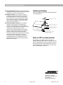
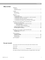
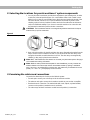
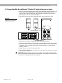
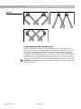
The Bose® Acoustimass® 5 Series III Speaker System
Owner’s Guide
October 22, 2001
AM196451_05_V.pdf
Introduction
English
Thank you
We appreciate your choice of the Bose® Acoustimass® 5 Series III speaker system. It will
provide you with many years of listening enjoyment. Your system features new third generation Acoustimass cube speaker arrays, a product of the continuous research and development at Bose Corporation. These cube speakers deliver more lifelike sound and better overall
performance, yet are smaller than their predecessors.
Important information
Please read this owner’s guide
The set-up and operation of your Acoustimass 5 Series III speaker system is significantly
different from other speakers. Please take the time to read this owner’s guide carefully. It will
help you set up and operate your system properly and enjoy all of its advanced features.
Save your owner’s guide for future reference.
Declaration
of Conformity
We, the offerer:
Bose® Corporation, The Mountain,
Framingham, MA 01701-9168 USA
acknowledge our sole responsibility, that the product:
Kind of equipment:
Type designation:
Loudspeakers
Acoustimass® 5 Series III Speakers
in accordance with EMC Directive 89/336/EEC and Article 10(1) of the
Directive, is in compliance with the following norm(s) or document(s):
Technical regulations:
EN50081-1, EN50082-1
Accredited by Bose Corporation
1 May 1998
Bose B.V., Nijverheidstraat 8
1135 GE Edam, The Netherlands
2
October 23, 2001
Anton Schalkamp
General Manager, Bose Europe
Manufacturer’s authorized EU representative
AM196451_05_V.pdf
Important Safety Instructions
1. Read these instructions – for all components
before using this product.
2. Keep these instructions – for future reference.
3. Heed all warnings – on the product and in the
owner’s guide.
4. Follow all instructions.
5. Do not use this apparatus near water or
moisture – Do not use this product near a
bathtub, washbowl, kitchen sink, laundry tub, in a
wet basement, near a swimming pool, or anywhere else that water or moisture are present.
6. Clean only with a dry cloth – and as directed
by Bose® Corporation. Unplug this product from
the wall outlet before cleaning.
7. Do not block any ventilation openings.
Install in accordance with the
manufacturer’s instructions – To ensure
reliable operation of the product and to protect it
from overheating, put the product in a position
and location that will not interfere with its proper
ventilation. For example, do not place the product
on a bed, sofa, or similar surface that may block
the ventilation openings. Do not put it in a built-in
system, such as a bookcase or a cabinet that may
keep air from flowing through its ventilation
openings.
8. Do not install near any heat sources, such
as radiators, heat registers, stoves or other
apparatus (including amplifiers) that produce heat.
9. Do not defeat the safety purpose of the
polarized or grounding-type plug. A polarized plug has two blades with one wider
than the other. A grounding-type plug has
two blades and a third grounding prong. The
wider blade or third prong are provided for
your safety. If the provided plug does not fit
in your outlet, consult an electrician for
replacement of the obsolete outlet.
10. Protect the power cord from being walked
on or pinched, particularly at plugs, convenience receptacles, and the point where
they exit from the apparatus.
11. Only use attachments/accessories specified by the manufacturer.
12. Use only with the cart, stand, tripod,
bracket or table specified by the
manufacturer or sold with the
apparatus. When a cart is used,
use caution when moving the
cart/apparatus combination to
avoid injury from tip-over.
13. Unplug this apparatus during lightning
storms or when unused for long periods of
time – to prevent damage to this product.
AM196451_05_V.pdf
14. Refer all servicing to qualified service personnel. Servicing is required when the apparatus
has been damaged in any way: such as powersupply cord or plug is damaged; liquid has
been spilled or objects have fallen into the
apparatus; the apparatus has been exposed to
rain or moisture, does not operate normally, or
has been dropped – Do not attempt to service this
product yourself. Opening or removing covers may
expose you to dangerous voltages or other hazards.
Please call Bose to be referred to an authorized
service center near you.
15. To prevent risk of fire or electric shock, avoid
overloading wall outlets, extension cords, or
integral convenience receptacles.
16. Do not let objects or liquids enter the product –
as they may touch dangerous voltage points or
short-out parts that could result in a fire or electric
shock.
17. See product enclosure for safety related
markings.
Information about products that
generate electrical noise
If applicable, this equipment has been tested and found
to comply with the limits for a Class B digital device,
pursuant to Part 15 of the FCC rules. These limits are
designed to provide reasonable protection against
harmful interference in a residential installation. This
equipment generates, uses, and can radiate radio
frequency energy and, if not installed and used in accordance with the instructions, may cause harmful interference to radio communications. However, this is no
guarantee that interference will not occur in a particular
installation. If this equipment does cause harmful interference to radio or television reception, which can be
determined by turning the equipment off and on, you are
encouraged to try to correct the interference by one or
more of the following measures:
• Reorient or relocate the receiving antenna.
• Increase the separation between the equipment and
receiver.
• Connect the equipment to an outlet on a different
circuit than the one to which the receiver is connected.
• Consult the dealer or an experienced radio/TV technician for help.
Note: Unauthorized modification of the receiver or radio
remote control could void the user’s authority to operate
this equipment.
This product complies with the Canadian ICES-003 Class
B specifications.
October 23, 2001
a
English
Important Safety Instructions
18. Use proper power sources – Plug the product into
a proper power source, as described in the operating
instructions or as marked on the product.
19. Avoid power lines – Use extreme care when
installing an outside antenna system to keep from
touching power lines or circuits, as contact with
them may be fatal. Do not install external antennas
near overhead power lines or other electric light or
power circuits, nor where an antenna can fall into
such circuits or power lines.
20. Ground all outdoor antennas – If an external
antenna or cable system is connected to this
product, be sure the antenna or cable system is
grounded. This will provide some protection against
voltage surges and built-up static charges.
Section 810 of the National Electrical Code ANSI/
NFPA No. 70 provides information with respect to
proper grounding of the mast and supporting
structure, grounding of the lead-in wire to an antenna
discharge unit, size of grounding conductors,
location of antenna-discharge unit, connection to
grounding electrodes, and requirements for the
ground electrode. Refer to the antenna grounding
illustration on this page.
Antenna grounding
Example of antenna grounding as per National Electrical
Code, ANSI/NFPA 70.
Antenna lead in wire
Ground clamp
Antenna discharge unit
(NEC Section 810-20)
Grounding conductors
Electric service
equipment
(NEC Section 810-21)
Ground clamps
Power service grounding
electrode system
(NEC ART 250, Part H)
Note to CATV system installer
This reminder is provided to call the CATV system
installer’s attention to Article 820-40 of the NEC (of USA)
that provides guidelines for proper grounding. In particular, it specifies that the cable ground shall be connected
to the grounding system of the building, as close to the
point of cable entry as is practical.
©2001 Bose Corporation,
The Mountain, Framingham, MA
01701-9168 USA
255805 AM Rev.00 JN10494
b
October 23, 2001
AM196451_05_V.pdf
Contents
Where to find…
Italiano
Product Information
Technical information .................................................................................................. 12
Available Accessories ................................................................................................. 12
Warranty period .......................................................................................................... 12
Customer Service ....................................................................................................... 12
Bose® Corporation .................................................................................... inside back cover
Français
Maintaining Your Acoustimass 5 Series III Speaker System
Maintaining your speaker system ............................................................................... 11
Troubleshooting .......................................................................................................... 11
Español
Fine Tuning Your Acoustimass 5 Series III Speaker System
Checking your speaker system .................................................................................... 8
Positioning your speaker system to get the best sound .............................................. 8
Cube considerations ........................................................................................... 8
Acoustimass module considerations .................................................................. 9
Using your speaker system to its best advantage ...................................................... 10
Automatic System Protection ..................................................................................... 10
Receiver/amplifier considerations ............................................................................... 10
Deutsch
Setting Up
Before you begin ........................................................................................................... 4
1. Unpacking the carton ............................................................................................... 4
2. Selecting the locations for your Acoustimass® system components ........................ 5
3. Examining the cables and connections .................................................................... 5
4. Connecting the cube arrays to the Acoustimass module ......................................... 6
5. Connecting the Acoustimass 5 Series III system to your receiver ........................... 7
Dansk
Contents
Where to find ................................................................................................................ 3
For your records ........................................................................................................... 3
English
Introduction
Thank you ..................................................................................................................... 2
Important information ................................................................................................... 2
Nederlands
For your records
Serial numbers are located on the connection panel of the Acoustimass module.
Serial number: _________________________________________________________________
Dealer name: __________________________________________________________________
Svenska
Dealer phone: _______________________ Purchase date: ___________________________
We suggest you keep your sales slip and warranty card together with this owner’s guide.
AM196451_05_V.pdf
October 23, 2001
3
Setting Up
English
Before you begin
The Bose® Acoustimass® 5 Series III speaker system offers many advantages over conventional speakers. For one, the system adjusts to deliver the best combination of direct and
reflected sound for your listening environment and musical taste. And this Virtually Invisible®
speaker system requires very little space to deliver a lifelike musical performance formerly
associated with room-dominating loudspeakers.
Sections 1 – 5 give you step-by-step instructions on how to set up and connect the system
to your components, so you can begin enjoying it as soon as possible. The remaining sections provide more detailed information on arranging your system for the best possible
performance.
1. Unpacking the carton
Unpack your system and familiarize yourself with the parts identified in Figure 1. If any part of
the product appears damaged, do not attempt to use the system. Repack it in the original
carton and notify Bose or your authorized Bose dealer immediately.
• Remove any staples from the opened carton flaps.
• Remove the inner cartons containing the two cube speaker arrays.
• Gently roll the carton over onto its side and then onto its opening.
• Carefully lift the carton from around the Acoustimass module and packing cushions.
WARNING: The Acoustimass module weighs 18.8 pounds (8.5 kg). Use good lifting
practice to avoid injury.
WARNING: To avoid danger of suffocation, keep the plastic bags out of the reach of
children.
Note: Now is a good time to record the serial number of these speakers on page 3 of this
guide and on your warranty card. It is a good idea to save all packing materials for possible
future use.
Figure 1
What comes in the carton:
• 2 Cube arrays
• 1 Acoustimass module
• 4 Wires
• 4 Adhesive-backed rubber
feet
• Owner’s guide
• Quick set up guide
4
October 23, 2001
AM196451_05_V.pdf
Setting Up
2. Selecting the locations for your Acoustimass® system components
English
1. You can place the Acoustimass module almost anywhere in your listening room, in either
a vertical or horizontal position (Figure 2). It can be hidden under a bed or table or even
behind a sofa, as long as you remember not to block the round opening in the end of the
unit. Allow at least 2 inches (5 cm) of space between that end and any surface. After
selecting a place for the Acoustimass module, attach the four rubber feet to the bottom
surface for additional stability. If you choose to stand the module on its connection end,
the feet must be attached to protect the wire connections.
CAUTION: The Acoustimass module is not magnetically shielded and should be kept at
least two feet (.6 m) from a television.
Figure 2
SPEATS
KERS
+
L
–
–
R
+
FROM
IN
–
AMP PUT
OR S
RECE
IV
R
ER
+
TO OU
CUBETPU
–
L
+
Acoustimass module positions
TS
OUTPU
SPEAKERS
+
– R
+
– L
TO CUBE
+
– L
INPUTS
OR RECEIVER
+
– R
FROM
AMP
2. Next, select the positions for the left and right cube arrays. Remember that wires from the
arrays connect to the Acoustimass module, so you should locate the cube arrays close
enough to the module to enable the wires to reach it. The cube arrays are magnetically
shielded, so they may be placed near a television.
Note: Bose® wall brackets and floor stands can increase your placement options. See page
12 for details and ordering information.
Note: While the wires provided are adequate for most installations, you may increase the
distance between the cube arrays and the Acoustimass module by splicing in additional
wire. If you do so, use similar gauge or thicker wire, and make sure you maintain the correct
phase (+ to + and – to –), and properly connect the wires.
3. Examining the cables and connections
Locate the four identical pairs of wires packed with the system.
• Two wire pairs connect your cube arrays to the Acoustimass module.
• The other two wire pairs connect the Acoustimass module to your receiver or amplifier.
• Examine the ends of the wires. The marked wire (with a red, striped, or printed marker)
connects to the positive (+) terminal at each connection.
• The cube arrays and the Acoustimass module have red positive (+) connections.
AM196451_05_V.pdf
October 23, 2001
5
English
Setting Up
4. Connecting the cube arrays to the Acoustimass® module
Select one pair of wires, and locate the terminal tab on the rear of the left cube array.
1. Just press the terminal tab on the back of the speaker to insert the marked wire into the
red (+) terminal and the plain wire into the black (–) terminal (Figure 3).
2. Release the terminal tab and both wires will be held securely.
3. Repeat this process with the other pair of wires and the right cube array.
Figure 3
Connecting a cube array
Marked wire
to red terminal
CAUTION: Do not connect your amplifier or receiver directly to the cube arrays. Cube
arrays must be connected directly to the Acoustimass module or damage will result.
4. Next, locate the terminals marked OUTPUTS TO CUBE SPEAKERS on the rear of the
Acoustimass module (Figure 4).
5. Connect the other ends of the wires from the left cube array to the pair of terminals
marked L. Make sure that the marked wire is connected to the positive (+) and the plain
wire is connected to the negative (–) terminal.
6. Now, repeat step 5 for the right cube array, connecting its wires to the terminals marked R.
Figure 4
Connecting cube arrays to the
Acoustimass module
From left cube speaker
From right cube speaker
To receiver or amplifier
6
October 23, 2001
AM196451_05_V.pdf
Setting Up
1. Select one of the remaining two pairs of wires, and locate the left channel terminals on the
Acoustimass module marked INPUTS FROM AMP OR RECEIVER. Depress the red,
positive (+) tab, insert the marked wire and release the tab. Repeat the process for the
black, negative (–) tab and the plain wire (Figure 5).
2. Then follow the same procedure for the right channel, using the last pair of wires.
Figure 5
Connecting the Acoustimass
module to your receiver
R
L
3. Disconnect your receiver or amplifier from the AC power (mains) outlet.
4. Locate the speaker outputs on your receiver. Connect the other ends of the wire from the
left channel of the Acoustimass module to the terminals marked L or LEFT. Make sure that
the marked wire is connected to the positive (+) and the plain wire is connected to the
negative (–) terminal.
5. Repeat these last two steps for the right channel.
6. Your set-up is complete. Plug in your receiver, turn the system on, and enjoy your Acoustimass 5 Series III speakers!
CAUTION: Before you plug in your receiver or amplifier, make sure that no strands of wire
from any terminal are brushing against any other terminal. Such “bridged” wires create short
circuits which can damage your receiver or amplifier.
AM196451_05_V.pdf
October 23, 2001
7
English
5. Connecting the Acoustimass® 5 Series III system to your receiver
English
Fine Tuning Your Acoustimass® 5 Series III Speaker System
Checking your speaker system
As you begin listening to your Acoustimass 5 Series III speaker system, the following test will
help you determine that it is working properly:
A. Turn the balance control on your receiver or amplifier all the way to the left. If you have
connected the cube arrays properly, you will hear the music from the left cube array, but
not the right one. You may notice a very faint sound issuing from the right cube array,
which is normal.
B. Now, turn the balance control all the way to the right. If your cube arrays are connected
properly, this time you will hear music only from the right one. You may also detect a very
faint sound from the other cube array.
C. Return the balance control to the center position. Play a musical selection with deep
bass. Now turn the balance control all the way to the left and listen, and then turn the
balance all the way to the right and listen. If the system is connected properly, the center
position should exhibit the same or greater bass response than either the left-only or
right-only positions. If it exhibits less, check to make sure that your components are
connected as described on pages 6 and 7.
D. Return the balance control to the center position.
If your system does not appear to be working properly, refer to the Troubleshooting section
on page 11.
Positioning your speaker system to get the best sound
Your Acoustimass 5 Series III speaker system may be used in a variety of ways. Here are
some guidelines.
Cube considerations
A. In average-sized listening rooms, the best stereo effects result when the left and right
cube arrays are spaced 6 to 12 feet apart (1.8 – 3.6 m). However, you can still achieve
excellent results with separation as little as 3 feet (1 m) or as great as 15 feet (4.5 m).
B. The cube arrays are magnetically shielded for use with video systems and may be placed
near your television without adversely affecting picture quality. However, the Acoustimass
module is not shielded and should be kept at least 2 feet (.6 m) from a television.
C. Though there is no “correct” position for the cube arrays or the angle between them, the
most lifelike effect will be achieved by providing a balance of direct and reflected sound.
Experiment with the positions of the cubes for the results you prefer. Figure 6 shows
some typical cube arrangements.
D. You may use the cube arrays with both cubes facing forward. This eliminates the benefits
of direct and reflected sound, but may be appropriate for very small listening areas.
8
October 23, 2001
AM196451_05_V.pdf
Fine Tuning Your Acoustimass® 5 Series III Speaker System
Figure 6
English
Cube array positions
Acoustimass module considerations
Unlike conventional floor standing or bookshelf speakers, you can fine tune the bass response of your Acoustimass 5 Series III speaker system without compromising an accurate
stereo image. Just change the location of the Acoustimass module within your listening
room. Placing it along a wall 3 to 5 feet (1 – 1.5 m) from a corner provides a normal balance
of frequencies from your speaker system. Moving the Acoustimass module closer to walls or
corners increases bass response while moving it away from walls or corners decreases bass.
In most rooms, it is easy to find a convenient location that provides pleasing bass response.
CAUTION: The Acoustimass module is not shielded and should not be placed within 2 feet
(.6 m) of a television.
AM196451_05_V.pdf
October 23, 2001
9
English
Fine Tuning Your Acoustimass® 5 Series III Speaker System
Using your speaker system to its best advantage
Your speaker system requires very little attention when set up and connected properly.
However, observing the following guidelines will help maximize your enjoyment.
Room Acoustics
The acoustics (sound properties) of your listening room can affect the overall sound quality of
any speaker system. The following tips will give you some control over the sound:
A. Rooms with a lot of sound-absorbing furnishings, such as stuffed furniture, wall-to-wall
carpet, or heavy drapes, may reduce the treble sound (high frequencies). The missing
treble sound can be restored by slightly turning up the treble control on your receiver or
amplifier. If convenient, you may remove some of the sound-absorbing material.
B. Rooms with too few sound absorbing furnishings, especially those with bare floors and
walls, may sound overly shrill or “bright” because of too much treble. Turning down the
treble control or adding sound absorbers such as throw carpets or drapes will usually
improve the sound.
C. If your system seems to have too much or too little bass (low frequencies), you can adjust
the bass control on your receiver or amplifier. You may also move the Acoustimass
module closer to a wall and/or corner to increase bass. Doing the opposite will decrease
bass.
D. In general, many problems with acoustics can be solved by the judicious use of your tone
controls. Remember, though, that the use of these controls (especially when turned all the
way up) may put greater power demands on your receiver or amplifier. Excessive tone
adjustment can cause an amplifier or receiver to run out of power and distort, potentially
damaging your system.
E. External signal processors (such as graphic and parametric equalizers), while not recommended, can be used with your Acoustimass 5 Series III speaker system if a greater
degree of acoustic control is desired. Consult your Bose® dealer for advice.
Automatic System Protection
Note: The Acoustimass 5 Series III speaker system incorporates an automatic protection
circuit, which guards against most kinds of damage from electrical stress or overload. This
circuit activates at high volume levels to reduce output, causing a slight decrease in volume.
This is normal operation and indicates that power input may be exceeding safe levels.
Sustained listening at these levels is not recommended.
Receiver/amplifier considerations
Note: Your speakers incorporate heavy-duty driver elements designed to resist many types
of electrical stress. However, any speaker can be damaged if the amplifier driving it fails.
Increasing the volume until the music sounds distorted also causes speaker damage. This
can happen even with a low-powered receiver or amplifier.
Your speaker system is designed for use with receivers or amplifiers rated from 10 to 200
watts per channel with 4 to 8 ohm impedance. For further information, refer to your receiver
or amplifier owner’s guide.
10
October 23, 2001
AM196451_05_V.pdf
Maintaining Your Acoustimass® 5 Series III Speaker System
English
Maintaining your speaker system
The cabinets of your Acoustimass 5 Series III speaker system may be cleaned with a soft
damp cloth. Do not use any sprays near the system or allow liquids to spill into any openings. Also, do not use any solvents, chemicals, or cleaning solutions containing alcohol,
ammonia, or abrasives.
The grille assemblies on the cube arrays may be carefully vacuumed if necessary. Please
note that the drivers are located directly behind the grille cloth, and are easily damaged if
reasonable care is not taken.
Troubleshooting
Problem
What to do
One of the cube arrays
does not play
• Turn off the receiver or amplifier. Check the wiring that connects the cube array to the
Acoustimass module, and the wiring that connects the module to the receiver or amplifier.
If no problem is found, disconnect the speaker wires at the back of the receiver. Reconnect only the wire from the channel in question to the opposite channel at the receiver.
Turn the balance control completely to that channel, and turn the power on. If the cube
array now works properly, the problem is in the receiver or amplifier.
• Do not connect the other cube array to the defective channel. It could damage your
speaker system.
The Acoustimass 5 speaker
system does not play or
sounds distorted
• Turn off the receiver or amplifier and disconnect the Acoustimass 5 speaker system.
Reconnect the system to another receiver known to be working properly. If the
Acoustimass 5 system now works properly, the problem is not in the speaker system.
• If this is the case, you should check all user accessible fuses on your receiver or amplifier
(see the appropriate owner’s guide for help). If the fuses blow again, have the unit checked
by qualified personnel.
• If trouble persists in your Acoustimass 5 speaker system, contact your authorized Bose®
dealer, who will verify any defects and arrange for service by an authorized agency or by
the Bose factory. Bose will make every effort to remedy any problem within the terms of
the warranty at minimum inconvenience to you.
AM196451_05_V.pdf
October 23, 2001
11
English
Product Information
Technical Information
Features
Direct/Reflecting® speaker design
Acoustimass® speaker system
Syncom® II computerized quality control
Automatic system protection circuitry
Driver Complement
Two 5.25 inch (13.3 cm) low-frequency drivers in Acoustimass module
Four 2.5 inch (6.4 cm) magnetically shielded, wide-range drivers in cube arrays
Compatibility
Compatible with receivers or amplifiers rated from 4 – 8 ohms
Compatible with receivers or amplifiers rated from 10 – 200 watts per channel
Finish
Acoustimass module: Scratch-resistant black or white satin finish
Cube arrays: Black or white polymer finish
Size/Weight
Cube arrays: 6.2"H x 3.1"W x 4.0"D (15.7 cm x 7.8 cm x 10.2 cm)
2.4 lb (1.09 kg)
Acoustimass module: 14.0"H x 19.0"W x 7.5"D (35.5 cm x 48.0 cm x 19.1 cm)
18.8 lb (8.5 kg)
Total shipping weight:
30.8 lb (14 kg)
Available Accessories
Floor stands: UFS-20B (black), UFS-20W (white)
Wall brackets: UB-20B (black), UB-20W (white)
Warranty period
The Bose® Acoustimass 5 Series III speaker system is covered by a limited 5-year transferable warranty. Details of the warranty are provided on the warranty card that came with your
system. Please fill out the information section on the card and mail it to Bose.
Customer service
For help in ordering accessories or solving problems, contact Bose Customer Service. See
the inside back cover for offices and phone numbers.
12
October 23, 2001
AM196451_05_V.pdf
Bose® Corporation
USA
Bose Corporation, The Mountain
Framingham, MA 01701-9168
1-800-367-4008
Phone hours - ET (eastern time):
Weekdays 8:30 a.m. to 8 p.m.
Saturdays 9 a.m. to 3 p.m.
Canada
Bose Ltd., 1-35 East Beaver Creek Road
Richmond Hill, Ontario L4B 1B3
1-800-465-2673
Phone hours - ET (eastern time):
Weekdays 9 a.m. to 5 p.m.
European Office
Bose Products B.V., Nijverheidstraat 8
1135 GE Edam, Nederland
TEL 0299-390111
FAX 0299-390114
Australia
Bose Australia, Inc., 1 Sorrell Street
Parramatta, N.S.W. 2150
TEL 02 9204-6111
FAX 02 9204-6122
Belgique/België
Bose N.V., Limesweg 2, B-3700 Tongeren
TEL 012-390800
FAX 012-390840
Danmark
Bose A/S, Industrivej 7, 2605 Brøndby
TEL 4343-7777
FAX 4343-7818
Deutschland
Bose GmbH, Max-Planck-Straße 36d
D-61381 Friedrichsdorf
TEL 06172-71040
FAX 06172-710419
France
Bose S.A., 6, rue Saint Vincent
78100 Saint Germain en Laye
TEL 01-30616363
FAX 01-30614105
India
Bose Corporation India Private Limited
W-16, Greater Kailash-II
New Delhi 110 048
TEL (011) 648 4462 FAX (011) 648 4463
Ireland
Bose Corporation
Carrickmacross, Co Monaghan
TEL (042) 9661988
FAX (042) 9661998
Italia
Bose S.p.A., Via della Magliana 876
00148 Roma
TEL 06-65670802
FAX 06-65680167
Japan
Bose K.K., Shibuya YT Building
28-3 Maruyama-cho
Shibuya-ku, Tokyo 150
TEL 3-5489-0955
FAX 3-5489-0592
Nederland
Bose B.V., Nijverheidstraat 8
1135 GE Edam
TEL 0299-390111
FAX 0299-390109
Norge
Bose A/S, Solheimsgate 11
N-2001, Lillestrøm
TEL 63-817380
FAX 63-810819
Österreich
Bose Ges.m.b.H., Vienna Business Park
Wienerbergstrasse 7 (10.OG)
A-1100 Vienna
TEL 01-60404340
FAX 01-604043423
Schweiz
Bose AG, Rünenbergerstrasse 13
4460-Gelterkinden
TEL 061-9815544
FAX 061-9815502
Sverige
Bose A/S, JohanneFredsgatan 4
S-43153 Mölndal
TEL 31-878850
FAX 31-274891
United Kingdom
Bose Limited
1 Ambley Green
Gillingham Business Park
Gillingham, Kent ME8 0NJ
TEL 0870-741-4500 FAX 0870-741-4545
From other locations
Bose Customer Service, 1 New York Ave.
Framingham, MA 01701-9168 USA
TEL (508) 766-1900 FAX (508) 766-1919
World Wide Web
www.bose.com
1
Warranty
© 1999 Bose Corporation, The Mountain,
Framingham, MA 01701-9168 USA
196451 AM Rev. 05 JN00049