1
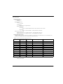
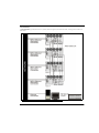
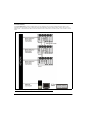
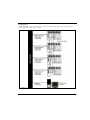
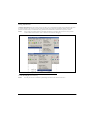
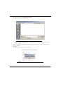
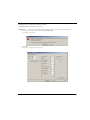
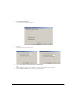
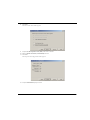
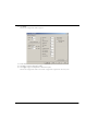
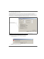
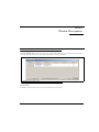
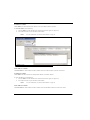
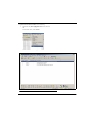
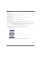
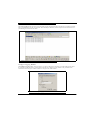
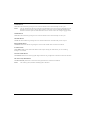
ADAM
TBX - TriBus
Triple Bus Expander for ADAM
93507838000 Rev A
12/2008
PROPRIETARY NOTICE
SHIPPING TO THE MANUFACTURER
The product information and design disclosed herein were originated by
and are the property of Telex Communications, Inc. Telex reserves all
patent, proprietary design, manufacturing, reproduction, use and sales
rights thereto, and to any article disclosed therein, except to the extent
rights are expressly granted to others.
All shipments of product should be made via UPS Ground, prepaid (you
may request from Factory Service a different shipment method). Any
shipment upgrades will be paid by the customer. The equipment should
be shipped in the original packing carton. If the original carton is not
available, use any suitable container that is rigid and of adequate size. If
a substitute container is used, the equipment should be wrapped in paper
and surrounded with at least four (4) inches of excelsior or similar
shock-absorbing material. All shipments must be sent to the following
address and must include the Proof of Purchase for warranty repair.
Upon completion of any repair the equipment will be returned via
United Parcel Service or specified shipper, collect.
COPYRIGHT NOTICE
Copyright 2008 by Telex Communications, Inc. All rights reserved.
Reproduction, in whole or in part, without prior written permission from
Telex is prohibited.
WARRANTY NOTICE
See the enclosed warranty card for further details.
CUSTOMER SUPPORT
Factory Service Department
Telex Communications, Inc.
8601 East Cornhusker Hwy.
Lincoln, NE 68507 U.S.A.
Attn: Service
Technical questions should be directed to:
Return Shipping Instructions EAME
Customer Service Department
RTS/Telex Communications, Inc.
12000 Portland Avenue South
Burnsville, MN 55337 USA
Telephone: 800-392-3497
Fax: 800-323-0498
Factory Service: 800-553-5992
Customer Service Department EVI Audio GmbH
After sales service Department
Hirschberger Ring 45
94315 Straubing
Germany
Technical Questions Europe
RTS/Telex Technical Support EMEA
Telex Communications (UK) Ltd
www.rtsintercoms.com
[email protected]
Phone: +44 1707 2809 60
RETURN SHIPPING INSTRUCTIONS
Customer Service Department
Telex Communications, Inc. (Lincoln, NE)
Telephone: 402-467-5321
Fax: 402-467-3279
Factory Service: 800-553-5992
Please include a note in the box which supplies the company name,
address, phone number, a person to contact regarding the repair, the type
and quantity of equipment, a description of the problem and the serial
number(s).
Table
of
Contents
INTRODUCTION ............................................. 3
General Description ...............................................3
VERSION REQUIREMENTS ..............................................3
Features ..................................................................4
Specifications ..........................................................5
Fail-Over Modes ....................................................6
FULL REDUNDANCY ......................................................7
PARTIAL REDUNDANCY .................................................8
NON-REDUNDANCY .......................................................9
Debug Information ...............................................13
APPLY BUTTON .......................................................... 31
TEST BUTTON ............................................................. 32
DONE BUTTON ........................................................... 32
Select Frame Window ...........................................32
IP ADDRESS 1 COLUMN ............................................. 32
MAC ADDRESS 1 COLUMN ........................................ 33
IP ADDRESS 2 COLUMN ............................................. 33
MAC ADDRESS 2 COLUMN ........................................ 33
OK BUTTON ............................................................... 33
CANCEL BUTTON ........................................................ 33
TBX Links Status Window ....................................34
CONFIGURE EACH MCII-E MASTER CONTROLLER
IP ADDRESS FOR THE ETHERNET ................................18
CONFIGURE THE SIZE OF YOUR INTERCOM
SYSTEM FOR EACH FRAME ...........................................19
CONFIGURE THE FRAME USING THE FRAME
MAPPING WINDOW IN AZEDIT .....................................23
TBX COLUMN ............................................................ 34
COMM COLUMN ......................................................... 34
(A) LINK UP/DN COLUMN ......................................... 35
(A) PARTNER COLUMN ............................................... 35
(B) LINK UP/DN COLUMN ......................................... 35
(B) PARTNER COLUMN ............................................... 35
(C) LINK UP/DN COLUMN ......................................... 35
(C) PARTNER COLUMN ............................................... 35
AUDIO A COLUMN ..................................................... 36
AUDIO B COLUMN ..................................................... 36
AUDIO C COLUMN ..................................................... 36
Base 8 vs. Base 16 Port Number Systems .............24
Intercom Alarms ...................................................36
BASE 8 PORT NUMBER SYSTEM ...................................24
BASE 16 PORT NUMBER SYSTEM .................................26
FRAME COLUMN ........................................................ 38
ALARM TIME COLUMN ............................................... 38
RESOLVED TIME COLUMN .......................................... 38
DESCRIPTION COLUMN .............................................. 38
Hiding and Clearing Alarms ................................. 38
INSTALLATION AND CONFIGURATION . 17
Installation ............................................................17
REQUIREMENTS ..........................................................17
Configuration .......................................................18
Force Autonomous Mode Check Box ...................27
AZedit Connections ..............................................28
WINDOW DESCRIPTIONS ........................... 29
Frame Mapping Table Window ............................29
FRAME COLUMN .........................................................29
IP ADDRESS 1 COLUMN ..............................................30
MAC ADDRESS 1 COLUMN .........................................30
IP ADDRESS 2 COLUMN ..............................................30
MAC ADDRESS 2 COLUMN .........................................30
BASE 16 COLUMN CHECK BOX ...................................31
MOVE UP BUTTON .....................................................31
MOVE DOWN BUTTON ................................................31
ACCEPT FRAME MAPPING TABLE FROM
OTHER FRAMES CHECK BOX ......................................31
Logging Window ...................................................39
Configure Logging Window .................................39
J1 RADIO BUTTON ..................................................... 40
J9 RADIO BUTTON ..................................................... 40
J10 RADIO BUTTON ................................................... 40
ETHERNET RADIO BUTTON ......................................... 40
IP ADDRESS FIELD .................................................... 40
ALL FRAMES RADIO BUTTON ..................................... 40
THIS FRAME ONLY RADIO BUTTON ............................ 40
DOWNLOAD FIRMWARE UPGRADES ......41
Download Firmware to the TBX-Tribus Card .....41
List
of
Figures
FIGURE 1.
FIGURE 2.
FIGURE 3.
FIGURE 4.
FIGURE 5.
FIGURE 6.
FIGURE 7.
FIGURE 8.
FIGURE 9.
FIGURE 10.
FIGURE 11.
FIGURE 12.
FIGURE 13.
FIGURE 14.
FIGURE 15.
FIGURE 16.
FIGURE 17.
FIGURE 18.
FIGURE 19.
FIGURE 20.
FIGURE 21.
FIGURE 22.
FIGURE 23.
FIGURE 24.
FIGURE 25.
FIGURE 26.
FIGURE 27.
FIGURE 28.
4 Frame System with Full Redundancy, including failover Master Controller ....................................7
Partially Redundant system, including failover Master Controller ......................................................8
4 Frame System with No Redundancy, including failover Master Controller ......................................9
Eight Frame Tribus System – Non-Redundant ...................................................................................11
Upload Debug Information .................................................................................................................13
Upload Debug Information window ...................................................................................................14
Uploading Debug Information Status window ...................................................................................14
Navigation to the Debug Folder for AZedit ........................................................................................15
Tribus Backcard Slots .........................................................................................................................17
Base 8 Port Numbering System Example ............................................................................................24
Base 8 Port Numbering scheme with both AIO-16 and an AIO-8 card
installed. ..............................................................................................................................................25
Base 16 Port Numbering System Example ..........................................................................................26
Force Autonomous Mode when no audio links up – Intercom Configuration|Options Tab ...............27
Connect To Frame Menu ....................................................................................................................28
Frame Mapping Table ........................................................................................................................29
Frame Mapping Table Browse Button which opens the Select Frame window. ................................30
Apply Button message .........................................................................................................................31
Frame Mapping Table Valid message ................................................................................................32
Select Frame Window .........................................................................................................................32
TBX Links Status Window ...................................................................................................................34
Intercom Alarm Indication ..................................................................................................................36
Intercom Alarms Window ...................................................................................................................37
Log Viewer Window ............................................................................................................................39
Configure Logging Window ................................................................................................................39
I/O Card Version Information Window ..............................................................................................41
Download Device Firmware Window .................................................................................................42
Download in Progress Window ..........................................................................................................42
Successful Download Message ...........................................................................................................43
CHAPTER 1
Introduction
General Description
A single TBX-Tribus fiber card can link up to eight (8) ADAM frames. This makes it possible to increase the number of
available users on a system by transparently integrating additional frames. The ADAM frame must be equipped with an
MCII-e Master Controller card (version 2.0.4 or later), allows the TBX-Tribus to link together multiple frames, thereby
allowing users to quickly connect multiple ADAM intercom systems. This functionality can be useful in mobile production
scenarios to tie systems together via fiber using the digital audio of the TBX-Tribus. In this scenario, the MCII-e Master
Controllers are tied together via Ethernet connections. In a failure of the Ethernet connection of one frame, the affected
ADAM can be automatically isolated as an autonomous frame, and the remaining frame(s) function as a normal
interconnected system. The TBX-Tribus works in both AIO-8 and AIO-16 frame environments with simple software settings
in AZedit intercom software. The TBX-Tribus card comes with a fiber connection only, allowing a range of up to 24.8 miles
(40km) between ADAM frames. The TBX-Tribus surpasses the DBX (Dual Bus Expansion) card with its superior channel
capability, transmitting 256 channels of audio, rather than the 128 channels supported by DBX.
Version Requirements
•
•
MCII-e version 2.0.4 or later
AZedit version 3.6.1 or later
3
Features
Interface
with ADAM
The TBX-Tribus card is backward compatible with all existing AES, AIO, and RVON cards in an ADAM
intercom system. The hardware and software is compatible to work seamlessly with the TDMa (Time
Division Multiplexing) and control bus circuitry for routing audio and controlling data. This card provides
a downloadable firmware feature through AZedit Intercom Software.
Channels
Per Link
The TBX-Tribus has three (3) fiber links. Each link can support up to a maximum of 256 audio channels
per link. This channel capability is provided in AIO-16 systems. Moreover, the link can also be scaled
down to 128 channels, allowing it to support AIO-8 based intercom systems.
New System
Architecture
The System Framework has been redefined for the TBX-Tribus allowing the system to reconfigure itself in
the event of a frame failure. In the scenario where the master frame fails, another ADAM frame within the
system seizes control until the fault is fixed. This fail-save mechanism monitors both audio and control,
and sends messages to report any corrupt behavior in the system.
NOTE:
DBX cards are not compatible with TBX-Tribus cards.
Support for
Multiple
Distances
The backcard features three (3) SFP (Small Form-Factor Pluggable) connectors that allow for support of
multiple distances. This allows the user to configure these cards based on their custom application. The
user can insert COTS (Commercial Off-The-Shelf) modules (Multi Mode/Single Mode) to match their
needs.
System
Expansion
The TBX-Tribus employs the next generation ASIC (Application Specific Integrated Circuit) Nucleus for
higher performance and future system expansion. See Table 1 on page 5.
Autonomous
Mode
Normally, a TBX-Tribus frame communicates with other frames that are part of the same intercom.
However, if an Ethernet link is not present, the Tribus automatically enters Autonomous mode.
AZedit also has a new option on the Intercom Configuration Options window (Options|Intercom
Configuration|Options Tab) called “Force Autonomous Mode when no audio links up.” The Force
Autonomous Mode check box is used to force the current frame into autonomous (independent) mode, if
none of its Tri-bus links are up. Normally, a frame communicates with other frames that are part of the
same intercom. If selected, the frame refuses to communicate with any other frames if none of its Tri-bus
links are up, even if Ethernet communications are fine. And, once one (1) or more of its audio links are
restored, the frame automatically tries to re-establish messaging links to the other frames in the cluster.
Automatic
Transfer of
Control
Within each frame, both the active and the standby MCII-e master controllers maintain Ethernet messaging
links with every other frame in the cluster. If the Active controller in the frame loses its messaging links,
but the standby controller has one (1) or more Ethernet links available, an automatic transfer of control is
performed. When this transfer occurs, the standby controller becomes the active controller and the
previously active controller becomes the standby controller when its messaging links are restored.
Alarms and
Warnings
A new view in AZedit displays various alarms and warnings that have occurred in the intercom. Once an
alarm has been resolved, it is deleted after five (5) minutes.
AZedit
Connections
AZedit Connections (Options|Connect to Frame) allow the user to select the frame AZedit should connect
to.
AZedit version 3.6.1 or higher is required.
Unavailable
Tally
Indicator
When a user turns a talk or listen key ON to connect with a resource in another frame within the cluster, the
key displays a busy tally, flashing between the Alpha and **, to indicate the resource is unavailable.
NOTE:
Logging
For special lists and party lines, no unavailable tally is generated if there are any members of
the special list or party line in accessible frames
Each frame in an intercom cluster generates its own log message and stores them locally. Normally, the log
messages are identical from frame to frame, except when frames are synchronizing. Using the logging
configuration window, you can select whether changes affect all frames in a cluster or just the locally
connected frame.
a. TDM is a technology that transmits multiple signals simultaneously over a single transmission path.
4
Specifications
Board Performance
Throughput Per Link:
360Mb/sec
SFP Fiber Transceivers:
Voltage:
3.3 V Rails
Standard Rate:
SONET OC12 or Gigabit Ethernet
Recommended Parts:
Multi-Mode:
Finisar - FTLF8519P2BNL (Oxide VCSEL, Maximum reach of 550m)
Single Mode:
Finisar - FTLF1422P1BTL (1310nm, Maximum reach 40km)
Fiber Cable Connector Type:
Multiple Mode Fiber LC–LC Duplex Connector – max length 500m (546.8 yd.)
Single Mode Fiber LC–LC Duplex Connector – max length 40km (24.9 miles)
Configuration Requirements
An MCII-e Master Controller card must be installed in the same frame as the TBX-Tribus. For more information, see
the MCII-e User Manual which can be found at www.rtsintercoms.com.
TABLE 1. Systems
Supported by the TBX-Tribus Card
# TBX Cards
per Frame
Links Used
System
Frames Supported
Channels
1
1
AIO-8
2
256
1
1
AIO-16
2
512
3
1
AIO-8
3
384
3
1
AIO-16
3
768
6
1
AIO-8
4
512
6
1
AIO-16
4
880
10
2
AIO-8
5
640
10
2
AIO-16
5
880
15
2
AIO-8
6
768
15
2
AIO-16
6
880
21
2
AIO-8
7
880
21
2
AIO-16
7
880
28
3
AIO-8
8
880
28
3
AIO-16
8
880
NOTE:
The TBX–Tribus supports up to eight (8) frames in non-redundant mode. Slot 10 should be used if a third TBX–
Tribus card is needed.
5
Fail-Over Modes
Unlike the DBX card, audio and communications (called control1) between frames is separated between the TBX-Tribus card
and the MCII-e Master Controller Card. Communication between frames using TBX-Tribus occurs using the MCII-e Master
Controller over Ethernet. Audio is passed between frames using the TBX-Tribus card fiber connection (see Figure 29 to
Figure 31).
Audio between frames exists as long as there is a single valid link between frames. There are three (3) types of system
configurations:
•
•
•
Full Redundancy
Partial Redundancy
Non-Redundancy
1. Control is the ability to talk to keypanels and act on key presses.
6
Full Redundancy
In Full Redundancy systems, there are two (2) links, shown in Figure 29, between each frame, so losing either one does not
affect audio.
FIGURE 29.
4 Frame System with Full Redundancy, including failover Master Controller
7
Partial Redundancy
In a Partial Redundancy systems, multiple frames, but not all frames, have two links configured between them. In the
example shown in Figure 30, Frame 1 and Frame 2 have full redundancy between them; however, Frame 3 has only one (1)
link to Frame 1. This means if the fiber connection between Frame 1 and Frame 3 is broken, Frame 3 can not send or receive
audio.
FIGURE 30.
8
Partially Redundant system, including failover Master Controller
Non-Redundancy
In a Non-Redundancy systems, shown in Figure 31, there is only one link between frames, so if the fiber link goes down,
audio communications between the frames is lost.
FIGURE 31.
4 Frame System with No Redundancy, including failover Master Controller
9
10
Figure 2: Eight Frame Tribus System – Non-Redundant
11
12
Debug Information
The Debug Information menu item, shown in Figure 32, allows you to send a flash file to RTS to help troubleshoot the reason
for crash in AZedit. In the event of a processor crash, the processor saves diagnostic information about the cause of the
problem to its flash memory. The menu item stays greyed-out until a flash file is created when the processor crashes.
NOTE:
Every card in every frames stores its own debug information. So, if frame 3 has a processor crash, you must
connect AZedit to frame three to create a .azd file to send to RTS for debugging.
FIGURE 32.
Upload Debug Information
To create the debug file, do the following:
NOTE:
Once the processor has crashed the Upload Debug Information menu item becomes active.
13
1.
From the Options menu, select Upload Debug Information.
The Upload Debug Information window appears.
FIGURE 33.
NOTE:
Upload Debug Information window
By default, the Debug folder (C:\Telex\AZedit\Debug) is where the AZedit debug file you create is
stored.
2.
In the File name field, enter a name for the debug file you create. For example, you could use the date as the file
name – 12152008.azd.
3.
Click Save.
The Uploading Debug Information Status window appears.
FIGURE 34.
14
Uploading Debug Information Status window
NOTE:
4.
Select the Delete debug information from intercom check box if you want to delete the debug
information from system once the .azd file is created. Otherwise, the information kept on the
intercom system. Remember, you will only be able to save the most current debug information.
This means that if your processor fails twice you will only be able to capture the second failure’s
diagnostic information.
Click OK.
The AZedit debug file is made.
To find the file you just created, do the following:
1.
Right-click on My Computer, and from the popup menu, select Explore.
The My Computer window appears with a navigation pane down the left hand side of the window.
2.
Navigate to C:\Telex\AZedit\Debug.
OR
Navigate to the folder you store your AZedit debug file.
The file you create is stored in this folder.
FIGURE 35.
Navigation to the Debug Folder for AZedit
Once you have created the AZedit Debug file, please contact your RTS system engineering for further instructions. If you do
not know your local system engineer, please see http://www.rtsintercoms.com/contact.php.
15
16
CHAPTER 2
Installation and Configuration
Installation
Requirements
•
•
•
10 Base-T or 100 Base TX Ethernet connection to the network
AZedit 3.6.1 or higher
MCII-e Master Controller 2.0.4 or higher
To install the Tribus into an ADAM frame, do the following:
1.
Firmly push the back card into slot 8, 9, or 10 in the ADAM frame.
NOTE:
Depending on the number of Tribus cards you are using determines the slot the card will occupy.
1 card = slot 8, 2 cards = slots 8 and 9, and 3 cards = slots 8, 9, 10.
2.
Using a screwdriver, secure the back card into the frame with the provided screws.
3.
Firmly push the front card into the front corresponding back card slot.
4.
Securely lock the front card in place with the top and bottom extractor handles.
FIGURE 36.
Tribus Backcard Slots
17
Configuration
To configure the TBX-Tribus card, the following steps must be completed for the Intercom System to be active:
Step 1
Configure each MCII-e Master Controller IP Address for the Ethernet (page 18)
Step 2
Configure the size of your Intercom system for each frame (page 19)
NOTE:
Step 3
Each frame must be configured exactly the same. The number of ports must not exceed the number
of ports allowed for the number of frames in the intercom system.
Configure the frame using the Frame Mapping window in AZedit (page 23)
Configure each MCII-e Master Controller IP Address for the Ethernet
To configure the IP Address for the MCII-e, do the following:
1.
Verify you are serially connected to AZedit.
You must be connected serially to make any changes to the Ethernet Setup window in AZedit.
2.
Open AZedit.
3.
From the Options menu, select Ethernet Setup.
The Ethernet Setup window appears.
4.
In the IP Address field, enter the IP Address for the MCII-e.
5.
In the Network Mask field, enter the Network Mask for the MCII-e, if applicable
6.
In the Default Gateway field, enter the Default Gateway for the MCII-e, if applicable.
NOTE:
18
If you are unsure of your IP Address, Network Mask, or Gateway Address, contact your System
Administrator for this information.
7.
Click Apply.
The IP Address is set for the MCII-e.
8.
Repeat steps 1-8 for each frame in your system.
Configure the size of your Intercom system for each frame
To configure the size of your frame, do the following:
IMPORTANT:
You must know the number of frames and the number of ports your intercom system supports.
1.
In AZedit, from the Options menu, select Intercom Configuration.
A warning message appears.
2.
Click OK.
The Intercom Configuration window appears.
19
20
3.
Click Intercom Sizing Wizard.
The Select Intercom Type window appears.
4.
Select the ADAM (multi-frame) radio button.
5.
Click Next.
The Select Intercom Size window appears.
6.
Select the The number of frames in the intercom radio button.
OR
Select the minimum number of ports required and enter the minimum number of ports you have.
7.
Enter the number of frames in your system (up to eight (8) frames).
8.
Click Next.
The Select Frame Links window appears.
9.
Verify the Tri-Bus Expander Cards (TBX) radio button is selected.
10.
Select the Enable Test Audio (recommended) check box.
11.
Click Next.
The Verify Intercom Configuration window appears.
12.
Verify the information displayed is correct.
21
22
13.
Click Finish.
The Intercom Configuration window reappears.
14.
Under Number of Ports in, make any changes to the frames for port allocation, as needed.
15.
Click Test to verify the configuration validity.
16.
Click Apply to apply the configuration to the intercom system.
The Intercom Configuration window closes and the configuration is applied to the intercom system.
Configure the frame using the Frame Mapping window in AZedit
To configure the frames with the Frame Mapping window, do the following:
TIP:
To save time from manually entering in the IP Addresses and MAC Addresses for all your frames, be sure to
connect to Ethernet. By being connected via Ethernet, you can browse for the other ADAM frame’s addresses,
select them, and automatically update the table.
1.
From the Options menu in AZedit, select Frame Mapping Table.
The Frame Mapping Table appears with the existing frame’s IP and MAC Address(es) already entered in the table.
2.
Click the Frame 2 IP Address 1 field.
The field becomes active and a browse button appears.
3.
Click the browse button.
The Select Frame window appears.
4.
Select the Frame(s) to add to the Frame Mapping Table.
5.
Click OK.
The Select Frame window closes and the frame information appears in the Frame Mapping Table.
6.
Using the Move Up and Move Down buttons, move the frame to the hierarchical position you desire.
7.
Repeat step 6 for all the frames in the intercom system.
8.
Click Test.
The results will tell you the mapping is either valid or invalid.
9.
Click Apply.
The frames are mapped together.
23
Base 8 vs. Base 16 Port Number Systems
With the advent of the TBX-Tribus card and the ever evolving technology to a 16-channel port system, Base 8 and Base 16
port number systems were created.
Base 8 Port Number System
The Base 8 Port Number System splits 16 ports between a top and bottom group. The bottom group starts with 1 through
136; the top group consists of ports 137 through 272 (see Figure 37).
EXAMPLE:
This means that if you have an AIO-16 in slot 1, ports 1–8 and 137–144 will be used by the AIO-16
card. Alternatively, if you have AIO-16’s in slots 1 and 3 and an AIO-8 in slot 2, the following port
mapping applies:
Figure 3. Example
for Base 8 Port Numbering
AIO-16 Ports 1– 8 and 137–144
FIGURE 37.
24
Ports 145-161 are not used when an AIO-8 card is in the slot
AIO-6 Ports 17–33 and 162–178
AIO–8 Ports 9–16
Base 8 Port Numbering System Example
FIGURE 38.
Base 8 Port Numbering scheme with both AIO-16 and an AIO-8 card
installed.
25
Base 16 Port Number System
The Base 16 Port Number System is newly supported with the TBX-Tribus Card. Unlike the Base 8 Port Number System,
where the ports were split into an upper and lower set of eight (8) ports, the Base 16 Port Number System puts all 16 ports in
one slot. This means, when you configure your intercom system to support Base 16, slot 1 in the ADAM holds ports 1–16, slot
2 holds ports 17 through 33, slot 3 holds 34 through 49, and so on. When a Tribus card is inserted into the frame, the port
numbering system jumps to the next available AIO card slot, see Figure 39.
FIGURE 39.
26
Base 16 Port Numbering System Example
Force Autonomous Mode Check Box
The Force Autonomous Mode check box, shown in Figure 40, is used to force the current frame into autonomous
(independent) mode, if none of its Tri-bus audio links are active. Normally, a frame communicates with other frames that are
part of the same intercom. However, the Options page of the Intercom Configuration dialog has a new option, Force
Autonomous Mode when no audio links up. If selected, the frame refuses to communicate with any other frames if none of its
Tri-bus links are up, even if Ethernet communications are fine. And, once one (1) or more of its audio links are restored, the
frame automatically tries to re-establish messaging links to the other frames in the cluster.
FIGURE 40.
Force Autonomous Mode when no audio links up – Intercom Configuration|Options Tab
To Force Autonomous Mode when no audio links are up, do the following:
1.
From the Options menu in AZedit, select Intercom Configuration.
A warning window appears.
2.
Click OK.
The Intercom Configuration window appears.
27
3.
Click the Options tab.
The Options page appears.
4.
Select the Force Autonomous Mode when no audio links up check box.
Force Autonomous Mode is activated.
5.
Click Apply.
The Intercom Configuration window closes.
AZedit Connections
The AZedit Connections menu item, shown in Figure 41, is used to select a frame to which AZedit connects. This menu also
has the option to Auto Connect. If this is selected, AZedit automatically tries to connect to another frame if it loses its
connection to the current frame.
NOTE:
This menu is only available when AZedit is configured to communicate using Ethernet.
TIP:
You can also change the frame, the serial port, or IP Address in the Communications window
(Options|Communications).
FIGURE 41.
28
Connect To Frame Menu
CHAPTER 3
Window Descriptions
Frame Mapping Table Window
The Frame Mapping Table window, shown in Figure 42, is used to link Tribus frames together. Determine the frame position
(1 through 8) and enter the primary and secondary MCII-e Master Controller IP Addresses.
FIGURE 42.
Frame Mapping Table
Frame Column
The Frame column displays the frame’s positional rank within the intercom system.
29
IP Address 1 Column
The IP Address 1 column indicates the IP Address of the Active MCII-e Master Controller.
To set the IP Address, do the following:
1.
Click the Address to make the field active and the Browse button appear (see Figure 43).
2.
Use the Browse button to open the Select Frame Window.
NOTE:
FIGURE 43.
For more information, see “Select Frame Window” on page 32.
Frame Mapping Table Browse Button which opens the Select Frame window.
MAC Address 1 Column
The MAC Address 1 column indicates the MAC Address of the active MCII-e Master Controller in the frame.
IP Address 2 Column
The IP Address 2 column indicates the standby MCII-e Master Controller IP Address.
To set the IP Address 2, do the following:
1.
Click the Address to make the field active and the Browse button appear (see Figure 43).
2.
Use the Browse button to open the Select Frame Window.
NOTE:
For more information, see “Select Frame Window” on page 32.
MAC Address 2 Column
The MAC Address 2 column indicates the MAC Address of the standard MCII-e Master Controller in the frame.
30
Base 16 Column Check Box
The Base 16 check box is used to enable the Base 16 port number system. For more information, see “Base 8 vs. Base 16 Port
Number Systems” on page 24.
Move Up Button
The Move Up button allows you to set the frame position of the system up in the Frame hierarchy. Frame 1 is the master frame
and holds the most complete frame mapping table. If frame 1 fails, then frame 2 becomes the master frame,
Move Down Button
The Move Down button allows you to set the frame position of the system down in the Frame hierarchy. Frame 1 is the master
frame and holds the most complete frame mapping table. If frame 1 fails, then frame 2 becomes the master frame,
Accept Frame Mapping Table from Other Frames Check Box
The Accept Frame Mapping Table from Other Frames check box is used to allow other frames to send their frame mapping
information to the selected frame.
NOTE:
Each frame in a valid system must be defined in a table map to be able to communicate with the other frames in
the system.
Apply Button
The Apply button is used to accept the modifications you make and send them to the Intercom System. Once the modifications
have been applied, AZedit displays the message below and then reboots itself.
FIGURE 44.
NOTE:
Apply Button message
You must press the Test button before the Apply button becomes active.
31
Test Button
The Test button is used to test the frame mapping configuration you create. Once you have tested your frame map
configuration, press the Apply button to implement the modifications you make. The message below appears if the frame map
is deemed valid.
FIGURE 45.
Frame Mapping Table Valid message
Done Button
The Done button is used to close the Frame Mapping window.
Select Frame Window
The Select Frame window, shown in Figure 46, is used to select a Frame (IP Address and MAC Address) to include in the
Frame Mapping table for your Tribus Intercom System.
FIGURE 46.
Select Frame Window
IP Address 1 Column
The IP Address 1 column displays the IP Address of the active master controller in the ADAM frame.
32
MAC Address 1 Column
The MAC Address 1 column displays the MAC Address of the active master controller in the ADAM frame.
IP Address 2 Column
The IP Address 2 column displays the IP Address of the standby master controller, if available, in the ADAM frame.
MAC Address 2 Column
The MAC Address 2 column displays the MAC Address of the standby master controller, if available, in the ADAM frame.
OK Button
The OK button is used to accept the selections made and close the window.
Cancel Button
The Cancel button is used to reject the selections made and close the window.
33
TBX Links Status Window
The TBX Links Status window, shown in Figure 47, is used to check the status of the TBX-Tribus card status. From this
window, you can also download firmware. For more information, see “Download Firmware Upgrades” on page 41.
FIGURE 47.
TBX Links Status Window
TBX Column
The TBX column displays TBX-Tribus cards listed by frame and slot number.
Example:
2 : 009 indicates the TBX card is in Frame 2 and occupying slot 9.
Comm Column
The Comm column displays the communications status of the TBX-Tribus card.
34
(A) Link Up/Dn Column
The (A) Link Up/Dn column displays the status of the links on the DBX port A.
Any of the following indicators may appear:
“—”
The link is down.
OK
The link is up for # hops.
(A) Partner Column
The (A) Partner column displays frame number of the TBX card to which the connection is made. For example, if Frame 1’s
A connector is connected to Frame 2, a 2 appears under the (A) Partner column.
NOTE:
If there are multiple TBX-Tribus cards in a frame, use the slot number to determine the card connection being
used.
(B) Link Up/Dn Column
The (B) Link Up/Dn column displays the status of the links on the DBX port B.
Any of the following indicators may appear:
“—”
The link is disabled.
OK
The link is active for # hops.
(B) Partner Column
The (B) Partner column displays frame number of the TBX card to which the connection is made. For example, if Frame 1’s
B connector is connected to Frame 2, a 2 appears under the (B) Partner column.
NOTE:
If there are multiple TBX-Tribus cards in a frame, use the slot number to determine the card connection being
used.
(C) Link Up/Dn Column
The (C) Link Up/Dn column displays the status of the links on the DBX port C.
Any of the following indicators may appear:
“—”
The link is disabled. If this is seen, the intercom ports were not configured correctly. See
“Configuration” on page 18 to read how to configure the ports.
OK
The link is active for # hops.
(C) Partner Column
The (C) Partner column displays frame number of the TBX card to which the connection is made. For example, if Frame 1’s
C connector is connected to Frame 2, a 2 appears under the (C) Partner column.
NOTE:
If there are multiple TBX-Tribus cards in a frame, use the slot number to determine the card connection being
used.
35
Audio A Column
The Audio A column displays the ports assigned to the Audio A link.
Audio B Column
The Audio B column displays the ports assigned to the Audio B link.
Audio C Column
The Audio C column displays the ports assigned to the Audio C link.
Intercom Alarms
The Intercom Alarms window, shown in Figure 49, displays alarms that occur in the intercom and an indication of whether
they have been resolved or not. If an alarm has not been resolved, it is highlighted in yellow on the status bar (see Figure 48).
Once an alarm has been resolved, it is automatically deleted out of the list after five (5) minutes.
FIGURE 48.
36
Intercom Alarm Indication
To open the Intercom Alarms window, do the following:
1.
Double-click the yellow highlighted alarm in the status bar.
OR
From the Status menu, select Alarms.
The Intercom Alarms window appears.
FIGURE 49.
Intercom Alarms Window
37
Frame Column
The Frame column displays the frame affected by the warning or alarm.
Alarm Time Column
The Alarm Time column displays the date and time (in 24-hour clock time) the alarm or warning occurred.
Resolved Time Column
The Resolved Time column displays the date and time (in 24-hour clock time) the alarm or warning was resolved.
Description Column
The Description column displays a description of the alarm or warning.
Hiding and Clearing Alarms
Some alarms can be cleared, as shown in the example below. Other alarms, such as loss of the backplane clock, can be hidden
but cannot be cleared. The only way to clear these alarms from the window is to resolve them.
Example: Lost communications with the Trunk Master. In this case, the alarm is not regenerated unless the alarm
condition is resolved, and then recurs. This means the Master Controller starts communicating with the
Trunk Master again, and then loses communications again.
NOTE:
You can also hide certain alarm type by selecting Hide this alarm type, if desired.
To hide or clear alarms/alarm types out of the Intercom Alarms window, do the following:
38
1.
Right-click the alarm you want to clear.
A popup menu appears.
2.
From the popup menu, select Hide this alarm, Clear this alarm or Hide this alarm type.
Logging Window
The AZedit Logging window, shown in Figure 50, displays the log messages about the events that have occurred in the cluster.
The log messages are kept locally on each frame. These normally are identical, with the exception of when the frames are resynchronizing, across the intercom cluster.
FIGURE 50.
Log Viewer Window
Configure Logging Window
The Configure Logging window, shown in Figure 51, is used to configure the connection type of the AZedit session where
log messages are sent when the Log to File option is selected. The Configure Logging window is only accessible when
connected to AZedit using the J1 serial connection or using the start AZedit session.
FIGURE 51.
Configure Logging Window
39
J1 Radio Button
The J1 radio button indicates log messages are sent to another AZedit session connected serially over the J1 port.
NOTE:
The only AZedit session allowed to configure the log destinations is the session currently configured as the start
destination for log messages or the main serial connection connected to J1 of the ADAM MC breakout panel.
Restrictions can be set up for the AZedit destination session to restrict access to the Configure Logging window.
J9 Radio Button
The J9 radio button indicates log messages are sent to another AZedit session connected serially over the J9 port.
J10 Radio Button
The J10 radio button indicates log messages are sent to another AZedit session connected serially over the J10 port.
Ethernet Radio Button
The Ethernet radio button indicates log messages are sent to another AZedit session connected over Ethernet.
IP Address Field
The IP Address field is used to enter the IP Address of the computer running the AZedit session you want to send log
messages to over Ethernet.
All Frames Radio Button
The All Frames radio button is used to apply all changes made to the Log Configuration to all frames connected to this frame.
This Frame Only Radio Button
The This Frame Only radio button is used to allow the log destination for each frame to be different.
NOTE:
40
The overall log status (enabled or disabled) applies to all frames.
CHAPTER 4
Download Firmware Upgrades
Download Firmware to the TBX-Tribus Card
To download firmware to the TBX-Tribus card, do the following:
1.
From the Status menu in AZedit, select Software Versions.
A flyout menu appears.
2.
From the flyout menu, select IO Cards.
The I/O Card Version Information Window appears.
FIGURE 52.
I/O Card Version Information Window
41
3.
Right-click on the TBX-Tribus card you want to download the firmware update to.
A popup menu appears.
4.
From the popup menu, select Download firmware....
The Firmware Download window appears.
5.
Using the Look in: drop down menu, navigate to the folder where the firmware is located.
6.
Click Open.
The Download Device Firmware window appears.
FIGURE 53.
7.
Click Begin Download.
The download begins. This takes a minute or two to occur.
FIGURE 54.
8.
42
Download Device Firmware Window
Download in Progress Window
When the download is finished, click OK.
The TBX-Tribus card firmware download is complete and a Success message appears.
FIGURE 55.
Successful Download Message
9.
Click OK.
The success message and Download Device Firmware window closes.
10.
From the Status menu, select I/O Cards.
The IO Card Status window appears.
11.
Verify the Tribus card firmware has been updated.
CAUTION:
Do not power down the frame or remove the TBX-Tribus card from the frame until you have
verified the new version information from AZedit. If the card loses power during download,
undesirable results may occur.
43