1
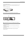
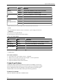
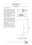
Express Ethernet Switch
August, 2002
LB9002A-ST-R2
Express
Ethernet Switches
CUSTOMER
SUPPORT
INFORMATION
1
Order toll-free in the U.S. 24 hours, 7 A.M. Monday to midnight Friday: 877-877-BBOX
FREE technical support, 24 hours a day, 7 days a week: Call 724-746-5500 or fax 724-746-0746
Mail order: Black Box Corporation, 1000 Park Drive, Lawrence, PA 15055-1018
Web site: www.blackbox.com • E-mail: [email protected]
Express Ethernet Switch
FEDERAL COMMUNICATIONS COMMISSION AND
CANADIAN DEPARTMENT OF COMMUNICATIONS
RADIO FREQUENCY INTERFERENCE STATEMENT
Class B Digital Device. This equipment has been tested and found to comply with the limits for a
Class B computing device pursuant to Part 15 of the FCC Rules. These limits are designed to provide
reasonable protection against harmful interference in a residential installation. However, there is no
guarantee that interference will not occur in a particular installation. This equipment generates, uses,
and can radiate radio frequency energy, and, if not installed and used in accordance with the
instructions, may cause harmful interference to radio communications. If this equipment does cause
harmful interference to radio or telephone reception, which can be determined by turning the
equipment off and on, the user is encouraged to try to correct the interference by one of the following
measures:
• Reorient or relocate the receiving antenna.
• Increase the separation between the equipment and receiver.
• Connect the equipment into an outlet on a circuit different from that to which the receiver is
connected.
• Consult an experienced radio/TV technician for help.
Caution:
Changes or modifications not expressly approved by the party responsible for
compliance could void the user’s authority to operate the equipment.
To meet FCC requirements, shielded cables and power cords are required to connect this device to a
personal computer or other Class B certified device.
This digital apparatus does not exceed the Class B limits for radio noise emission from digital
apparatus set out in the Radio Interference Regulation of the Canadian Department of
Communications.
Le présent appareil numérique n’émet pas de bruits radioélectriques dépassant les limites applicables
aux appareils numériques de la classe B prescrites dans le Règlement sur le brouillage radioélectrique
publié par le ministère des Communications du Canada.
Normas Oficiales Mexicanas (NOM)
INSTRUCCIONES DE SEGURIDAD
1. Todas las instrucciones de seguridad y operación deberán ser leídas antes de que el aparato
eléctrico sea operado.
2. Las instrucciones de seguridad y operación deberán ser guardadas para referencia futura.
3. Todas las advertencias en el aparato eléctrico y en sus instrucciones de operación deben ser
respetadas.
4. Todas las instrucciones de operación y uso deben ser seguidas.
5. El aparato eléctrico no deberá ser usado cerca del agua—por ejemplo, cerca de la tina de baño,
lavabo, sótano mojado o cerca de una alberca, etc.
6. El aparato eléctrico debe ser usado únicamente con carritos o pedestales que sean
recomendados por el fabricante.
7. El aparato eléctrico debe ser montado a la pared o al techo sólo como sea recomendado por el
fabricante.
2
Express Ethernet Switch
8. Servicio—El usuario no debe intentar dar servicio al equipo eléctrico más allá a lo descrito en
las instrucciones de operación. Todo otro servicio deberá ser referido a personal de servicio
calificado.
9. El aparato eléctrico debe ser situado de tal manera que su posición no interfiera su uso. La
colocación del aparato eléctrico sobre una cama, sofá, alfombra o superficie similar puede
bloquea la ventilación, no se debe colocar en libreros o gabinetes que impidan el flujo de aire
por los orificios de ventilación.
10. El equipo eléctrico deber ser situado fuera del alcance de fuentes de calor como radiadores,
registros de calor, estufas u otros aparatos (incluyendo amplificadores) que producen calor.
11. El aparato eléctrico deberá ser connectado a una fuente de poder sólo del tipo descrito en el
instructivo de operación, o como se indique en el aparato.
12. Precaución debe ser tomada de tal manera que la tierra fisica y la polarización del equipo no
sea eliminada.
13. Los cables de la fuente de poder deben ser guiados de tal manera que no sean pisados ni
pellizcados por objetos colocados sobre o contra ellos, poniendo particular atención a los
contactos y receptáculos donde salen del aparato.
14. El equipo eléctrico debe ser limpiado únicamente de acuerdo a las recomendaciones del
fabricante.
15. En caso de existir, una antena externa deberá ser localizada lejos de las lineas de energia.
16. El cable de corriente deberá ser desconectado del cuando el equipo no sea usado por un largo
periodo de tiempo.
17. Cuidado debe ser tomado de tal manera que objectos liquidos no sean derramados sobre la
cubierta u orificios de ventilación.
18. Servicio por personal calificado deberá ser provisto cuando:
A: El cable de poder o el contacto ha sido dañado; u
B: Objectos han caído o líquido ha sido derramado dentro del aparato; o
C: El aparato ha sido expuesto a la lluvia; o
D: El aparato parece no operar normalmente o muestra un cambio en su desempeño; o
E: El aparato ha sido tirado o su cubierta ha sido dañada.
3
Express Ethernet Switch
About This Manual
This manual describes the Black Box Express Ethernet Switch in these basic sections:
?? Product Features
?? Installation
?? Trouble-shooting
?? Glossary of Terms
Product Features
This section examines the key features, the physical features, and the product specifications
of each model.
Installation
This section leads with a Quick Tip, and continues with a detailed description of
Connecting to Power and Connecting to Your Network with the two types of cable: copperbased and fiber-optic. The section concludes with instructions on using the Uplink Function.
Trouble-shooting
This guide leads you through trouble-shooting the most common networking problems.
Glossary
A brief glossary defines the terms used in this manual.
4
Express Ethernet Switch
This manual services the compact size of Express Ethernet Switch, LB9002A-SC/ST, which
has 1 port TX and 1 port FX.
5
Express Ethernet Switch
Table of Contents
About This Manual ............................................................................................................................4
Product Features ...............................................................................................................................4
Installation .........................................................................................................................................4
Trouble-shooting ..............................................................................................................................4
Glossary..............................................................................................................................................4
Product Features.................................................................................................................................7
Key Features......................................................................................................................................7
Physical Features ..............................................................................................................................8
Illustrated Compact-Size Switches ...........................................................................................9
LB9002A-SC-R2/LB9002A-ST-R2.....................................................................................9
Fiber Module Installation .........................................................................................................10
Product Specifications .................................................................................................................... 10
Installation ......................................................................................................................................... 12
Quick Tip .........................................................................................................................................12
Connecting to Power......................................................................................................................12
Connecting to Your Network .......................................................................................................12
Copper-based cabling................................................................................................................12
Fiber-optic cabling.....................................................................................................................13
Uplink or MDI Function ...............................................................................................................13
No Power to the Switch.................................................................................................................14
No Connectivity to the Data Terminal Equipment...................................................................14
No Connectivity to Certain Nodes on the Network..................................................................14
Transmission Problems .................................................................................................................15
Trademarks....................................................................................................................................... 16
Glossary.............................................................................................................................................. 16
6
Express Ethernet Switch
Product Features
This section addresses:
?? Key Features
?? Physical Features (including LEDs)
?? Product Specification
Key Features
?? Auto-negotiation for speed and duplex on every TX port
?? Plug & play
?? True non-blocking architecture
?? Full wire-speed forwarding
?? Store-and-forward switching mechanism
?? Runt and CRC filtering eliminate erroneous packets to optimize network bandwidth
?? Back pressure for half-duplex
?? IEEE 802.3x flow control for full-duplex
?? MAC address filtering and relearning that automatically adjusts to the network
configuration
?? Comprehensive array of LED indicators that communicate the status of the switch and
trouble-shooting information
?? Designed in compliance with 10BASE-T, IEEE802.3u, 100BASE-TX, and 100BASEFX standards
?? Full compatibility with standard Ethernet applications, internetworking systems, and
client-side adapters to minimize migration cost
7
Express Ethernet Switch
Physical Features
??
??
??
??
??
??
??
AC Input:100-250VAC, 47-63Hz internal universal power supply
Input Fuse: 2A
Power Consumption: 7W
Operating Temperature: 0 C- 40 C (32 F- 104 F)
Storage Temperature: -25 C- 70 C (-13 F-158 F)
Humidity: 10%-90% non-condensing
Emission Compliance: FCC part 15 class B, CE Mark, VCCI Class
B
?? Safety: UL
?? Dimensions: W254mm x D135mm x H36mm (10" x 5.3” x 1.4")
?? Net weight: 0.9kg (2.1lb)
8
Express Ethernet Switch
Illustrated Compact-Size Switches
The front panel of the compact switch has two or eight ports and LED indicators to provide
instant feedback on the status of the switch. This group includes LB9002A-SC/ST, and
LB9108A.
LB9002A-SC-R2/LB9002A-ST-R2
Figure 1: Compact-size, 2-port with fiber LB9002A-SC-R2 (also available in ST)
?
100FX
LNK/ACT PWR
10/100TX
MDI
MDI-X
TX
RX
FDX/COL 100
??
?
Figure 2: LED and functions of the two-port switch (LB9002A-SC-R2 & LB9002A-STR2)
? Port Status for the FX port
Two LEDs , LNK/ACT and FDX/COL, convey the status of the port as detailed on the
following table
? Port Status for the TX port
Three LEDs, LNK/ACT, FDX/COL, and 100, convey the status of the port as detailed on
the following table.
Table 1: Port status display LEDs for compact-size, 1 port TX, 1 port FX (part#
LB9002A-ST/SC-R2)
9
Express Ethernet Switch
LED
State
LNK/ACT
Steady
(link/activity)
Flashing
The port is receiving or transmitting data
Steady
The port has established a valid 100 Mbps connection
Off
The port has established a valid 10 Mbps network connection
Steady
The connection is in full-duplex mode
Flashing
Collision occurred in the 10/100 domain
Off
The connection is in half-duplex mode
100
FDX/COL
(full-duplex/collision)
Indication
The port has established a valid network connection
*Collision will only occur on the half-duplex mode of transmission between two devices.
? Power
This LED illuminates when the switch is connected to a power supply and turned on.
? MDI Button
Also referred to as the uplink button.
The following chart details the LED status displays.
Table 2: Port Status Display
LED
State
LNK (link)
Steady
ACT (activity)
Flashing
The port is transmitting or receiving data
Steady
The connection is in full-duplex mode
Off
The connection is in half-duplex mode
FDX (full-duplex)
Indication
The port has established a valid network connection
? Uplink button
Fiber Module Installation
?? Turn off the power. The module is not hot- swappable.
?? Remove the cover plate, retaining screws and plate for later replacement
?? Slide in the module, following the guides
?? Snap in the module to attain a firm connection
Product Specifications
All Black Box Express Ethernet Switches auto-negotiate 10/100 Mbps, use store-andforward and non-blocking architectures and use back pressure for half-duplex and IEEE
802.3x compliant flow-control for full-duplex. The Express Ethernet Switches support
substantial MAC entries with address filtering and relearning capabilities.
ETHERNET STANDARDS
IEEE 802.3 10BASE-T; IEEE 802.3u 100BASE-TX/FX
10
Express Ethernet Switch
CABLE
10BASE-T: 2-pair UTP Cat. 3, 4, or 5;
100BASE-TX: 2-pair UTP Cat. 5;
100BASE-FX: 62.5/125 multi-mode fiber-optic cable
SWITCHING M ETHOD
Store-and-Forward
FORWARDING RATE
14,800 pps for 10 Mbps;
148,800 pps for 100 Mbps
TEMPERATURE
Operating: 32 to 104°F (0 to 40°C)
Storage: -13 to +158°F (-25 to +70°C)
HUMIDITY
10 to 90% non-condensing
EMISSION COMPLIANCE AND SAFETY STANDARDS
FCC part 15 Class B, CE Mark, VCCI, cUL
11
Express Ethernet Switch
Table 8: Specifications per model
Model
Dimension "W x "D x "H
Weight
Output
Pwr
LB9002A-SC/ST
10 x 5.3 x 1.4
2.1 lb.
0.9 kg
100-250VAC
7W
25.4 x 13.5 x 3.6 cm
47-63 Hz
Installation
Quick Tip
Install a Black Box Express Ethernet Switch as a plug-and-play device. No special
configuration is required. Details below are consistent with the installation of any electronic
device
Place the Black Box Express Ethernet Switch where it will not be subjected to extreme
temperatures, humidity, or electromagnetic interference. Specifically, the site you select
should meet the following requirements:
?? The room temperature should be between 32 and 104 degrees Fahrenheit (0 to 40
degrees Celsius).
?? The relative humidity should be less than 90 percent, non-condensing.
?? Surrounding electrical devices should not exceed the electromagnetic field (RFC)
standards for IEC 801-3, Level 2 (3V/M) field strength.
?? Make sure that the switch receives adequate ventilation. Do not block the ventilation
holes on the side of the switch or the fan exhaust port on the rear of the switch.
?? The power outlet should be within 1.8 meters of the switch.
Connecting to Power
Connect the supplied AC power cord to the receptacle on the back of the switch, and then
plug the cord into a standard AC outlet with a voltage range from 100 to 120 VAC. For
external power supply units, plug the jack into the DC receptacle on the front of the unit,
and plug the power supply unit into a 110~220 AC outlet.
Turn the switch on by flipping the ON/OFF switch on the rear of the unit to the I (ON)
position. The O position is OFF.
Connecting to Your Network
If you are making a connection to a server or workstation, be sure that it has a properly
installed 100BASE-TX (or 100BASE-FX if the switch does not contain 100BASE-TX
ports) network interface card. Connect the RX/TX jacks on the target device to the TX/RX
jacks on the switch and the RJ-45 jacks on the target device to the RJ-45 jacks on the
switch.
Use the uplink port for connecting to a regular (i.e. non-uplink) port of a hub or another
switch. If connecting to an uplink port of a hub or another switch, use any port. There is no
uplink issue with fiber ports.
Copper-based cabling
Connect cables to computers or network segments into the RJ-45 ports on the front of the
switch.
12
Express Ethernet Switch
The cable must be a Category 5 shielded twisted-pair or unshielded twisted-pair (STP/UTP)
cable for 100BASE-TX, or Category 3, 4, or 5 STP/UTP cable for 10BASE-T. Consult
Table 9 for further details.
Fiber-optic cabling
Prepare a pair of fiber optic cables with SC or ST type connectors at both ends. The cable
for fiber ports must be a 62.5/125 micron fiber-optic cable for 100BASE-FX. Consult Table
9 for further details.
Table 9: Cable Specifications
Speed
Connector
Port Speed
Cable
Range
Half/Full
Duplex
100BASE-TX
RJ-45
100/200 Mbps
Category 5 UTP
100 meters
10BASE-T
RJ-45
10/20 Mbps
Category 3, 4, or 5 UTP
100 meters
ST or SC
200 Mbps
62.5/125 micron fiberoptic cable
2 kilo-meters
100BASE-FX
Uplink or MDI Function
A network of switches connected (or cascaded) together via uplink ports is termed a
“collapsed backbone.” The uplink function transforms the adjacent or indicated port into an
uplink port with a push of the button or by sliding the switch. This allows connection to
another switch or hub without preparing crossover cable. However, this is unnecessary
when either connecting directly to the uplink port of another switch or hub or when
connecting fiber ports between switches or hubs.
13
Express Ethernet Switch
Trouble-shooting Guide
This trouble-shooting guide describes problems that could occur with the Express Ethernet
Switch. The guide states possible reasons for the problems, and possible steps to take to
solve the problems.
No Power to the Switch.
Symptom: Power cord is connected to the switch, but all LEDs, including the Power LED,
are off.
Possible
Solution
Problem
1.
Loose power
connection or
faulty power supply
2.
Check both ends of the power cord to make certain that they are securely connected to the power receptacle
on the switch and to t he power outlet.
Verify that the power outlet has power.
No Connectivity to the Data Terminal Equipment.
Symptom: An Ethernet switch cannot communicate to the directly connected computers or
network segments.
Possible
Solution
Problem
1.
Check cables for a secure connection.
2.
Verify that the correct type of cable is in use.
??
For connection to a PC or a network interface card (NIC), use a straight-through cable.
??
For uplink to another switch or hub, use a cross-wire cable, or use a regular straight-through cable connected
to the uplink port with the uplink button activated.
Incorrect or faulty
?? Refer to Table 9 for cable specifications.
cabling
1. Verify proper cable preparation.
2. Use a time domain reflectometer (TDR) or other cable-checking device to verify that the cable has no opens,
shorts, or other problems.
3. Swap the cable with another of the same kind to see if the cable is bad.
??
Replace or fix the faulty cable as necessary.
Dysfunctional NIC Run the diagnostic supplied by the vendor on the NIC to determine if it is functioning properly. If it is not, replace
on a PC or
it.
workstation
Packet Overflow or Reset the switch by pressing the reset button or turn the switch off, then on again.
Hardware problem
No Connectivity to Certain Nodes on the Network
Symptom: Data terminal equipment (DTE) connected to the switch can not send or receive
information from certain segments on the same network or across to another LAN or WAN.
Possible
Problem
Solution
Hardware problem Check for a damaged RJ-45 jack, or fiber SC or ST type connector.
14
Express Ethernet Switch
Transmission Problems
Symptom: Connections across a LAN switch are slow or unreliable.
Possible
Solution
Problem
Express Ethernet Switches are all equipped with auto-negotiation to communicate with other DTEs on the
Incorrect full- or network for the best available performance.
half-duplex
1. Verify if the connected NIC is equipped with auto-negotiation (this is not the same as auto-sensing).
settings
2. Change the DIP switch setting if available.
1.
refer to Table 9.
Exceeded cabling
distance or
Ensure that the proper cable is in use and that the recommended distance is not exceeded. For information,
2.
misused cable
Check the cable distance using a cable tester or TDR. Verify that the cable lengths attached to the switch
meet Ethernet/IEEE 802.3 specifications.
3.
If the distance is out of specification, reduce the length of the cable or add a repeater, ensuring no more than
four repeaters are attached.
Bad adapter in
Check the switch port statistics. If excessive errors are found, run the adapter card diagnostic utility to determine
attached device
the problem.
15
Express Ethernet Switch
Trademarks
Any trademarks are acknowledged to be the property of the trademark owners.
Glossary
10BASE-T
100BASE-TX
100BASE-FX
autonegotiation
Category 5
collision
Ethernet
Fast Ethernet
fiber-optic
cable
full-duplex
half-duplex
IEEE 802
LAN
MAC address
Mbps
segment
store -andforward
switch
UTP
wire speed
16
Networking standard for twisted-pair cabling capable of carrying data at 10 Mbps.
Networking standard for two pairs of high -quality twisted-pair wires carrying data at 100 Mbps.
Networking standard for fiber-optic cabling capable of carrying data at 100 Mbps.
Two-part process by which a network device automatically senses the speed and duplex capability of another
device.
Networking standard certifying that a copper wire cable can carry data at up to 100 Mbps.
Concurrent Ethernet transmissions from two or more devices on the same segment.
Networking standard for transmitting data at 10 Mbps.
Networking standard for transmitting data at 100 Mbps.
Cable made of thin glass threads that carry data in the form of light pulses.
A communications technique that allows bi-directional, simultaneous transmission between two devices on a single
segment.
A communications technique in which one device on a segment transmits while the other receives, then the process
is reversed.
Set of Institute of Electrical and Electronic Engineers standards for defining methods of access and control on
LANs.
Local area network. A network where computers are connected in close proxim ity, such as in the same building or
office park. A system of LANs connected at a distance is called a wide -area network (WAN).
Media access control address. A hardware address that uniquely identifies each node of a network.
Millions of bits per second.
Section of a network bounded by bridges, routers, hubs, or switches. Dividing an Ethernet into multiple segments is
a common way to increase bandwidth on a LAN.
Switching feature where the port receives the entire incoming frame and stores it in the buffers while checking for
runts and error frames before forwarding it to the destination port.
Device that filters and forwards packets between LAN segments.
Unshielded twisted pair; cabling with wires that are twisted around each other. The individual wires are not
insulated.
The ability to handle the fastest rate of traffic that a generator can deliver without dropping packets. On a 100 Mbps
connection, wire-speed traffic is 148,809 packet s per second using 64-byte frames or 8,127 packets per second using
1,518-byte frames.