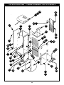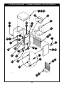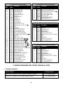
1
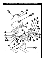
Innovative Foodservice Equipment Custom Designed for Performance, Service and Value. Convection Heated Holding Cabinets OPERATION & MAINTENANCE MANUAL MODELS: CA34-CV9 CA43-CV7 or CV13 CA70-CV16 or CV32 CA34-CVMP4 CA43-CVMP6 CA70-CVMP12 CS34-CH9 CS43-CH7 or CH13 CS72-CH16 or CH32 CS34-CHUS4 CS43-CHUS6 CS70-CHUS15 CS43-CVMP6-SB CS61-CVMP12-SB CS71-CVMP15-SB Phone: Fax: Toll Free: Website: E-mail: P/N 780085 1/06 +1 (214) 421-7366 +1 (214) 565-0976 +1 (800) 441-1601 www.BevLes.com [email protected] BevLes 729 Third Avenue Dallas, TX 75226 1 TABLE OF CONTENTS 1 2 2-1 2-2 2-3 2-4 2-5 3 3-1 3-2 4 4-1 4-2 4-3 4-4 5 5-1 5-2 6 6-1 6-1a 6-1b 6-1c 6-1d 6-1e 6-1f 6-1g 6-1h 6-1i 6-1j 6-1k 6-1l 6-1m 6-1n 6-1o 7 7-1 7-2 7-3 7-4 7-5 7-6 8 8-1a 8-1b WARRANTY GETTING STARTED INTRODUCTION MODELS UNPACKING SETTING-UP CLEANING. OPERATION OPERATING CONTROLS AND COMPONENTS OPERATIONAL PROCEDURES CARE OF YOUR UNIT ASSISTANCE SAFETY AND HEALTH CLEANING MODEL SPECIFICATIONS TROUBLESHOOTING TROUBLESHOOTING TROUBLESHOOTING TABLE MAINTENANCE REPLACING PARTS REMOVING THE TOP MOUNTED HEATING MODULE REMOVING THE FRONT PANEL POWER INDICATOR LAMP MODULE THERMOSTAT INDICATOR LAMP MODULE POWER SWITCH THERMOMETER POWER CORD FOR CA70 POWER CORD FOR CA43 THERMOSTAT FOR CA70 THERMOSTAT FOR CA43 FAN BLOWER MOTOR ASSEMBLY HEATING ELEMENT HIGH-TEMPERATURE SAFETY THERMOSTAT TOP MOUNTED HEATING MODULE SEAL (GASKET) FAN BLOWER COOLING FAN FOR CA43 REPLACEMENT PARTS HOW TO ORDER PRICES SHIPPING WARRANTY PARTS DRAWINGS PARTS LISTS w/EXPLODED VIEWS WIRING DIAGRAMS CA70 MODELS CA43 MODELS 2 3 4 4 4 4 5 5 6 6 6 7 7 7 7 7 7 7 8 9 9 9 9 9 10 10 11 11 12 13 14 16 17 18 18 18 19 19 19 19 19 19 20 29 29 29 1. WARRANTY BEVLES COMPANY LIMITED WARRANTY 729 Third Avenue * Dallas, TX 75226 Phone: +1 (214) 421-7366 Fax: +1 (214) 565-0976 1. Bevles warrants to the original purchaser that on the date the equipment is shipped (sold), it will be free of defects in materials or workmanship. Bevles will, at its discretion, repair or replace, during the warranty period printed below, any part that has a defect in material or workmanship that was present when the product shipped from Bevles, and which manifests itself during the warranty period under normal use and service. ! ! Parts: Two* years from date of original shipment from the Bevles factory. Labor: One** year from date of original shipment from the Bevles factory. * Air Circulation Blower Assemblies (motors) and Power Switches shall be one year from date of original shipment. Calrod Air Heating Elements shall be three years from date of original shipment. ** All electrical components 120 days from date of original shipment. 2. Bevles must be contacted, and pre-approval must be issued by the Bevles factory prior to any type of service being performed. Bevles assumes no responsibility for any charges that were not expressly authorized by the Bevles factory, or for any charges that exceed, in Bevles sole judgement, normal and customary amounts. 3. Bevles will pay UPS Ground charges for any part that has a defect in material or workmanship that was present when the product shipped from Bevles, and which manifests itself during the first year of the warranty period under normal use and service. All warranty replacement parts will ship F.O.B. Bevles factory, Cheyenne, WY 82003. 4. This warranty shall be void in its entirety if any abuse of, misuse of, alteration/modification of or improper maintenance of original product occurs. If, at any time a claim is reported to Bevles, the purchaser is delinquent in payment for the product, warranty will not apply. 5. Buyers Remedies-If a Bevles product fails due to a defect in material or workmanship in conformity with the warranties in paragraph one, buyer shall notify Bevles of such failure within a reasonable time, but in no event beyond fifteen (15) days of such discovery of defect in material or workmanship. Bevles shall provide, in its sole discretion, either the repair or replacement of any defective or any non-conforming part. Bevles specifically disavows any other representation, warranty or liability relating to the continued use of the product. 6 Exclusion of consequential and incidental damages-In no event shall Bevles be liable for any incidental, special, indirect, or consequential damages, whether resulting from non-delivery or from the use, misuse, or inability to use the product, or from defects in the product, or from Bevles own negligence or other tort. This exclusion applies regardless of whether such damages are sought for breach of warranty, breach of contract, negligence, or strict liability in tort or under any other legal theory. 7. Disclaimer of warranties-The warranties contained in paragraph one above are the exclusive warranties given by Bevles and supersede any prior, contrary, or additional representations, whether oral or written. Bevles hereby disclaims and excludes all other warranties-whether expressed, implied, or statutory-including any warranty of merchantability, any warranty of fitness for a particular purpose, and any implied warranties otherwise arising from course of 4/02 1/05 dealing or usage of trade. 3 2. GETTING STARTED 2-1 INTRODUCTION BEVLES Heated Holding Cabinets are quality built equipment designed to hold prepared foods at a safe temperature (no less than 140°), with or without humidity. These cabinets have a wide range of applications for both institutional and commercial foodservice operations This manual has been prepared so that all personnel responsible for the operation and maintenance of this equipment will have a thorough understanding of its operation and use. We recommend that any personnel using the cabinet read this manual thoroughly before operating the equipment. **NOTE: Certain items of information and procedures will be highlighted with the words "NOTE" or "WARNING”. Please make special note of these items as they will communicate important information for the safety of your personnel, and the continued quality of service provided by the equipment. 2-2 MODELS All BEVLES Heated Holding Cabinets are designed to hold hot products at the desired holding temperature. They accomplish this through patented air and humidity systems that force heated, moist air laterally across each level of the cabinet from side mounted air-flow ducts. Each cabinet also offers certain features that make them extremely easy to use, clean and service: ! ! ! ! The easily removable top mounted heating module contains all of the cabinet's electrical components. Dutch doors are mounted on the front with a full-length door on the back (for 70 inch models). All doors are removable and equipped with patented positive extruded latches. Standard models offer right-hand swing doors, but all cabinet doors can be hinged either left or right. Heavy-duty ball bearing casters provide easy and reliable mobility (for 70 inch and 43 inch models). This manual applies to the following models: CA70-CV16 CA 70-CV16HW CA 70-CV32 CA70-CVMP15 CA43-CV7 CA43-CV7HW CA43-CVMP6 CA43-CVMP7 CA 70-CV32HW CA43-CV13 CA70-CVMP12 CA43-CV13HW 2-3 UNPACKING **NOTE: All BEVLES cabinets are tested, inspected and expertly packed to insure arrival in a ready-to-use condition. If damage or loss is discovered when unpacking, ask the carrier's agent (in writing) to inspect the goods. This should be done within 15 days of delivery. You can then file a formal claim with the carrier. If we can help in any way, please call us. This product has been shipped on a wooden base, packed with secure padding and covered with a plastic bag and corrugated shipping container. To open: 1. 2. 3. 4. 5. Carefully cut the metal banding. Lift the shipping container off of the unit. Lift the unit off of the wooden base. WARNING: Use extreme care in lifting to prevent personal injury. Remove the plastic bag and properly dispose of it. Check model number on the serial number label (located on the top right front corner of the right side of the unit) against the packing slip. 6. Open doors and remove packing materials. 7. NOTE: Before using, the cabinet should be thoroughly cleaned as instructed in section 2-5 of this manual. 4 2-4 SETTING-UP Locate your holding cabinet in an area where the doors can be opened without impeding your operation and where loading and unloading product will be easy. **WARNING: A clearance of at least four (4) inches is required between the top of full size units (models beginning with CA70) and any other equipment or surfaces to allow air to circulate to the motor air vents. Do not set anything on top of these units. Proper operation of the unit requires that it be level and that it be plugged into a separate electrical line protected by a fuse or circuit breaker of the proper rating. CA70-CV16 120V/1500W/14.3A CA43-CV7 120V/1500W/14.3A CA70-CV16HW 120V/2000W/18.5A CA43-CV7HW 120V/2000W/17.0A CA70-CV32 120V/1500W/14.3A CA43-CV13 120V/1500W/14.3A CA70-CV32HW 120V/2000W/18.5A CA43-CV13HW 120V/2000W/17.0A CA70-CVMP12 120V/2000WI18.5A CA43-CVMP6 120V/2000W/17.0A CA70-CVMP15 120V/2000W/18.5A CA43-CVMP7 120V/2000W/17.0A WARNING: Plug your unit only .into a grounded receptacle of the correct voltage. Check the serial number label located in the top right front corner on the right side of the cabinet to determine your unit's electrical rating. 2-5 CLEANING **NOTE: Never use steel wool or caustic cleaning compounds on your BEVLES holding cabinet. Figure 1 Figure 2 Figure 3 Cleaning Steps: 1. Push power switch to the OFF position. 2. Unplug power cord from wall. CAUTION: Always unplug the unit before dismantling or cleaning. 3. Remove front and back doors by lifting entire door and sliding hinge off of hinge pins. (Fig. 1) **NOTE: Avoid motions other than straight up or down when removing and replacing doors so as not to damage hinges. 4. Slide out stainless steel water pan containing the three "U" shaped baffles. 5. Lift off the heating module from the top of the cabinet. (Fig.2) **NOTE: At least two people should do the lifting to avoid possible injury. 6. Remove all trays. 7. Remove tray supports by carefully lifting each panel and tilting the bottom toward the center of the cabinet. (Fig. 3) **NOTE: Handle the support panels carefully as any damage or bending will make reinstallation very difficult 8. Remove positive door latches (Fig. 4): 8a. Firmly hold the latch plate against the edge of the door and pull the black capped pin up and out. 8b. Slowly pull the latch plate away from the door, ready to catch the flat metal spring as it releases. 9. Models equipped with dutch doors will also have a removable wiper blade attached to the top of the bottom door. To remove this, loosen the two black knurled knobs at either end of the wiper blade retainer. Lift off the stainless steel retainer and the Figure 4 wiper blade. 5 10. 2. 3. 4. 5. 6. Clean all pieces thoroughly and carefully with soapy water and soft cloths. **NOTE: Neverusesteelwoolorcausticcleaningcompounds. **CAUTION: Avoid splashing water or any other liquid into the heating module to prevent possible damage to electrical components. Reassembly Steps: 1. Replace door latches (Fig.5): 1a. Wrap the flat metal latch spring lip around the front edge of the door between the two latch butts. 1b. Place the latch plate with the flat side out over the flat metal latch spring and press firmly in place. 1c. Guide the black capped pin down through the top latch butt, the latch plate and bottom latch butt. This will require positive pressure on the Figure 5 latch plate to compress the spring. Replace dutch door wiper blade if your model is equipped with one. Simply slide the gasket and retainer onto the top edge of the bottom door and re-tighten the two black knurled knobs. Carefully replace top mounted heating module and align with top tray supports. Replace tray support panels. Replace doors by sliding door hinges back down onto the hinge pins. You are now ready to operate your unit in accordance with the procedures outlined in section 3-2. 3. OPERATION BEVLES Heated Holding Cabinets are not intended for any use other than as foodservice equipment. Always operate your unit in accordance with the Operational Procedures listed in section 3-2 of this manual. 3.1 OPERATING CONTROLS AND COMPONENTS (Fig. 6) 1. Power Switch 2. Power Switch Indicator lamp 3. Thermostat 4. Thermostat Indicator Lamp 5. Thermometer 3-2 OPERATIONAL PROCEDURES Figure 7 Figure 6 1. Plug unit into wall. CAUTION: Check the serial number label located on the right side of the cabinet (as you are facing the front of the unit) at the top to be sure that your unit is compatible with your electrical supply. See section 4-4 for more information. 2. If humidity is desired, fill water pan % full of water and adjust baffles. (Fig. 7) 2a. For maximum humidity, all three baffles should be inserted into the water pan as though they were the letter "U" (open side up). 2b. For minimum humidity, all three baffles should be inserted in the water pan as though they were the letter "n" (open side down). 2c. Intermediate levels of humidity may be achieved by mixing the arrangement of the baffles. 3. Slide the water pan into its receptacle at the top of the cabinet, just under the heating module. Carefully push the pan to assure that it is seated against the water pan back stop. 4. Push on the power switch. The power indicator light should come on. You should also hear the blower fan(s) operating. 5. Set the thermostat to the desired holding temperature (140° to 200°F). The red thermostat indicator light should come on. 6. Check your cabinet after 5 minutes to be sure that the heating element(s) is functioning. 7. When the cabinet reaches your desired temperature, the thermostat indicator light will go out (though the power indicator light will remain illuminated). 8. Check and add water to the water pan from time to time during long periods of operation (if needed). **CAUTION: The water pan is located directly under the heating element(s). Always use extreme caution when removing or replacing the water pan to prevent injury (burn). 6 4. CARE OF YOUR UNIT As with any piece of quality equipment, your BEVLES Heated Holding Cabinet requires regular care and maintenance. The most vital procedure is the regular and thorough cleaning of the entire unit. For your assistance, we have included the following sections in this manual: 2-4 Setting Up 5 Troubleshooting 7-6 Parts List 2-5 Cleaning 6-1 Replacing Parts 8-1 Wiring Diagrams 4-1 ASSISTANCE BEVLES is proud of each quality-built cabinet. Should you ever need assistance, parts or additional equipment just call the BEVLES Manufacturing Facilities at (800) 441-1601. In addition, refer to the Troubleshooting (5) and Replacement Steps (6-1) sections of this manual for assistance if occasional maintenance questions should arise. 4-2 SAFETY AND HEALTH BEVLES Heated Holding Cabinets carry both UL and NSF listings. Always operate your unit in accordance with the operational procedures found in section 3-2. **CAUTION: Never remove the top mounted heating module without first unplugging your cabinet from its power source. 4-3 CLEANING Refer to section 2-5 for complete cleaning steps and procedures. 4-4 MODEL SPECIFICATIONS Model CA 70-CV16 CA70-CV16HW* CA 70-CV32 CA 70-CV32HW* CA70-CVMP12* CA70-CVMP15* CA43-CV7A CA43-CV7HW* CA43-CV13 CA43-CV13HW* CA43-CVMP6* CA43-CVMP7* Capacity Capacity Dimensions Vertical Pan (18” x 26” Pans) (12” x 20” Pans) Height Width Depth Spacing 3 1/4" 3 1/4” 1 1/2" 1 1/2” 4" 3 1/4" 3 1/4" 3 1/4” 1 1/2" 1 1/2” 4" 3 1/4" 16 16 32 32 12 15 7 7 13 13 6 7 70'' 70" 70" 70'' 70" 70'' 42" 42” 42” 42” 42” 42” 24 30 12 14 24 ½” 24 ½” 24 ½” 24 ½” 29 29 24 ½” 24 ½” 24 ½” 24 ½” 29” 29” 31" 31" 31" 31" 31" 31" 31" 31" 31" 31" 31" 31” Watts Electrical Volts Amps 1500 2000 1500 2000 2000 2000 1500 2000 1500 2000 2000 2000 120/240 120/240 120/240 120/240 120/240 120/240 120/240 120/240 120/240 120/240 120/240 120/240 14.3/7.2 18.5/9.3 14.3/7.2 18.5/9.3 18.5/9.3 18.5/9.3 14.3/7.2 17.0/8.5 14.3/7.2 17.0/8.5 17.0/8.5 17.0/8.5 *Units furnished with 20 AMP plug and cord, NEMA #5-20R 5. TROUBLESHOOTING If you find that your unit is failing to operate properly refer first to the Operational Procedures in section 3-2 of this manual. Then, if necessary, use the Troubleshooting guide in section 5 to determine the cause of the problem. **CAUTION: All maintenance on BEVLES Heating Holding Cabinets should be performed by trained personnel using only quality BEVLES parts. 5-1 TROUBLESHOOTING To determine the cause of any malfunction: 1. Determine the problem (e.g., the food isn't staying hot). 2. Locate the problem in the Troubleshooting table. 3. Read through the possible causes ,then try each solution listed until the problem is resolved. 7 4. If you are unable to locate the problem in the table or if the solutions listed don't work, please call the BEVLES manufacturing facilities for assistance at (800) 441-1601. You will need to provide the factory personnel with the following information: 1. The product model and serial numbers. 2. The specific nature of the problem. In some cases it will be beneficial to also have the actual operator of the equipment available to answer questions. 5-2 TROUBLESHOOTING TABLE Problem 1. Unit will not heat. Possible Cause Solution Power switch not in on position. Place the power switch in the ON position. Loose or unplugged power cord. Plug power cord into proper electrical outlet. Thermostat on wrong setting. Set thermostat to correct temperature. Faulty thermostat (not switching heating Replace thermostat per section 6element on when below set temperature). 1i or j. Faulty internal wiring. Check connections for heating m o d u l e c o m p o n e n ts p e r sections 6-11. Faulty heating element (not getting hot). Replace heating element per section 6-11. Hi-temperature safety thermostat on. Check for failure of heating element and/or thermostat not shutting down. Doors left open or ajar. 2. Unit not reaching Close doors firmly and keep closed or holding desired except. when loading or unloading Temperature uniformly. product. Thermostat on wrong setting. Set thermostat to correct temperature. Faulty thermostat (not switching heating Replace thermostat per section element on when below set temperature). 6-1i or j. Faulty internal wiring. Check connections for heating module components per section 611 Top mounted heating module seal Replace gasket per section 6-1 m. (gasket) torn or worn. Faulty heater fan blower (no air Replace fan blower motor per circulating). section 6-1k. Faulty thermostat (not switching heating Replace thermostat per section 6-1i 3. Unit overheating. element off when above set temperature). or j. Power switch not in on position. 4. Fan blowers not Place the power switch in the on operating. position. Loose or unplugged power cord. Plug power cord into proper electrical outlet. Faulty heater fan blower. Replace fan blower motor per section 6-1k. Faulty internal wiring. Check connections for heating module components per sections 6-11. Too much humidity in air flow. 5. Cabinet steamy and Adjust baffles per section 3-2. Holding temperature not high enough. too humid. Adjust thermostat to a higher temperature level. Holding product too long in cabinet. Minimize holding time. Water pan dry. 6. Cabinet too dry. Fill 3/4 full with water. Not enough humidity in air flow. Adjust baffles per section 3-2. Holding temperature too high. Adjust thermostat to a lower temperature (never below 140°F). 8 6. MAINTENANCE **CAUTION: All maintenance on BEVLES Heating Holding Cabinets should be performed by trained personnel using only quality BEVLES parts. 6-1 REPLACING PARTS After using the Troubleshooting table (section 5-2) to determine the solution, refer to the appropriate section below. The tools and equipment needed for each repIacement procedure are listed at the beginning of that procedure. 6-1a. Removing the top mounted heating module. Required: No tools required 1. Unplug unit from power source. 2. Open top front door and remove water pan and baffles. 3. Using two people, lift the top mounted heating module straight up and off of the cabinet (Fig. 8) 4. Set module upside down on a heat resistant surface. 6-1b. Removing the front panel from the heating module. Required: Medium (6') phillips screwdriver, Medium (6') flathead screwdriver 1. Remove all five screws from the face of the front panel (at the four corners and center top). 2. Gently lift off the front panel while guiding attached wires and thermometer probe to prevent damage. (Fig. 9) 3. Leaving wires attached, gently place front panel face down on a clean work space. (Fig. 10) 4. To replace front cover, reinsert thermometer probe into receptacle, guide wires back into place and reattach panel with the five phillips head screws. Figure 8 Figure 9 Figure 10 Figure 11 Figure 12 Figure 13 6-1c. Replacing the power indicator lamp module. Required: Wiring markers (color or number codes), Electrical tape 1. Remove front panel as found in section 6-1b. 2. Mark all the wires connected to the power indicator lamp module with a color code or number to make proper re-connection easy (Fig. 11) 3. Remove the wire nuts and free the power indicator lamp module wires. 4. From the back side of the front panel, depress the plastic tabs on the base of the indicator lamp module and push it out the front of the panel. (Fig. 12) 9 5. Feed the wires of the replacement indicator lamp module through the opening and snap the new indicator lamp module into place. 6. Reconnect wiring with each of the two new wires going to a different wire nut (it doesn't matter how you match the new module wires). Re-tape over wire nuts and wires. **WARNING: Be sure to correctly match the other wires that were connected at the two wire nuts. 7. Replace the front panel (section 6-1b). 6-1d. Replacing the thermostat indicator lamp module. Required: Medium (6") flathead screwdriver, Medium (6”) phillips screwdriver, Wiring markers (color or number codes), Electrical tape 1. Remove front panel as found in section 6-1 b. 2. Mark all the wires connected to the thermostat indicator lamp module and thermostat with a color code or number to make proper re-connection easy. (Fig. 11) 3. Locate the thermostat indicator lamp module wire that connects to a wire nut and remove that wire nut, freeing all wires. (Fig. 13) 4. Remove the indicator lamp module wire from the terminal on the back of the thermostat by removing the electrical tape and reversing the screw. 5. From the back side of the front panel, depress the plastic tabs on the base of the indicator lamp module and push it out the front of the panel. (Fig. 12) 6. Feed the wires of the replacement indicator lamp module through the opening and snap the new indicator lamp module into place. 7. Reconnect wiring with one of the two new wires going to the wire nut and the other to the back of the thermostat (it doesn't matter how you match the new module wires). Re-tape over wire nuts and wires. *'WARNING: Be sure to correctly match the other wires that were connected at the wire nut 8. Replace the front panel (section 6-1 b). 6-1e. Replacing the power switch. Required: Wiring markers (color or number codes), Electrical tape, Wiring diagram for CA43 and CA70 (see step 7 below) 1. Remove front panel as found in section 6-1b. 2. Trace the four wires from the power switch to the wire nuts. Code all wires connected by the four wire nuts to insure proper re-connection. (Fig. 14) 3. Remove the wire nuts and free the power switch wires. 4. From the back side of the front panel, depress the plastic tabs on the base of the power switch and push it out the front of the panel. (Fig. 15) 5. Feed the wires of the replacement switch through the opening and snap the new (4) (5) power switch into place. Klixon 6. Reconnect wires using the four wire nuts (0) (Grd) Thermostat and the wiring diagram. Re-tape over wire (2) (1) Cooling nuts and wires. (Diagram 1) (3) Fan **WARNING: Severe damage can be Power Cord caused to your unit by improperly (0) connecting wiring. Heating 7. Replace the front panel (section 6-1b). (1) (4) Element Fan (1) (0) (0) Blower (5) (1) Thermostat Power (5) (1) Indicator Lamp Thermostat (0) (1) (2) (3) Power Switch Figure 14 Diagram 1 Figure 15 10 Indicator Lamp Figure 16 Figure 17 Figure 18 6.1f. Replacing the thermometer. Required: Crescent or standard 3/4" wrench 1. Remove front panel as found in section 6-1b. 2. Use a crescent or standard 3/4" wrench to loosen the thermometer mounting nut that holds the thermometer in place on the back of the front panel. (Fig. 16) 3. Remove the nut, washer and retaining bracket and pull thermometer out the front of the panel. 4. Replace retaining bracket and insert new thermometer into opening. **NOTE: Align thermometer so that the 150° reading will be straight up when the front panel is replaced and the heating module is flipped over. (Fig. 17) 5. Replace and tighten washer and nut on rear of front panel. DO NOT OVER TIGHTEN! 6. Replace the front panel (section 6-1b). 6-1g. Replacing the power cord for a CA70 unit. Required: Medium (6”) phillips screwdriver, Medium (6") flathead screwdriver, Wiring markers (color or number codes), Electrical tape, Wiring diagram for CA70 (see step 10) 1. Remove top mounted heating module and front panel as found in sections 6-1a and 6-1b. 2. Mark all the wires connected to the power cord with a color code or number to make proper re-connection easy. (Fig. 18) . 3. Turn the top mounted heating unit over so that the elbow connector for the power cord is up. Free the green ground wire by grasping the nut with fingers or pliers (under front overhang of the heating module) and remove the screw from the exposed surface of the module with a medium (6") phillips screwdriver. (Fig. 19). 4. Free the other two power cord wires by removing the two wire nuts that connect them. 5. Remove elbow connector that secures power cord into the heating module by grasping the nut holding the connector (under the overhang of the heating module). Rotate the nut to loosen and remove the elbow from the module. (Fig. 20) 6. Remove the two screws that secure the power cord into the compression end of the elbow connector with a medium (6”) flathead screwdriver. Pull gently to free power cord from the elbow connector. (Fig. 21) 7. Insert new power cord into elbow connector and replace compression screws. Tighten screws to secure power cord into connector. **WARNING: Replace only with a BEVLES power cord properly rated for your unit. 8. Insert new wires through opening in the heating module and reattach elbow connector. 9. Reattach green ground wire to module. 10. Reconnect power cord wires using wire nuts and wiring diagram. Re-tape over wire nuts and wires. (Diagram 2) **WARNING: Severe damage can be caused to your unit by improperly connecting wiring. 11. Replace the front panel and top mounted heating module (sections 6-1a. and 6-1 b). Figure 19 11 6-1h. Replacing the power cord for a CA43. Required: Medium (6”) phillips screwdriver, Medium (6") flathead screwdriver, Wiring markers (color or number codes), Electrical tape , Wiring diagram for CA43(see step 10) 1. Remove the back panel of the module by removing the five phillips head screws and gently lifting out the back panel. Lay the panel on a clean work surface. (Fig. 22) (4) Figure 20 (5) (1) Klixon (Grd) (0) Cooling Fan Thermostat (2) (3) Power Cord (0) (5) Heating (4) Element (0) (1) (1) Fan Blower Thermostat (0) (5) (1) (0) (2) Power Indicator Lamp Figure 23 (3) Power Switch Thermostat Indicator Lamp Diagram 2 Figure 21 Figure 22 (1) (1) 2. Mark all the wires connected to the power cord with a color code or number to make proper re-connection easy. (Fig. 23) 3. Free the green ground wire by grasping the nut with fingers or pliers (inside the back panel of module) and remove screw from the outside surface of the panel with a medium (6") phillips screwdriver. (Fig. 24) 4. Free the other two power cord wires by removing the two wire nuts they are attached to. 5. Remove elbow connector that secures power cord onto the back panel. While grasping the nut (on the inside surface of the panel) and holding the connector (on the outside surface of the panel), rotate the nut to loosen and remove the elbow from the panel. (Fig. 25) . 6. Remove the two screws that secure the power cord into the compression end of the elbow connector with a medium (6”) flathead screwdriver. Pull gently to free power cord from the elbow connector. (Fig. 26) 7. Insert new power cord into elbow connector and replace compression screws. Tighten screws to secure power cord into connector. *"WARNING: Replace only with a BEVLES power cord properly rated for your unit. 8. Insert new wires through opening in back panel and reattach elbow connector. 9. Reattach green ground wire to back panel. 10. Reconnect power cord wires using wire nuts and wiring diagram. Retape over wire nuts and wires. (Diagram 3) **WARNING: Severe damage can be caused to your unit by improperly connecting wires. 11. Replace the back panel using the five phillips head screws. 12 Figure 25 Figure 24 (0) (1) (0) (4) Power Cord Heating (1) Power (4) Element (1) Thermostat (0) (5) (1) Indicator Lamp (5) Klixon (0) (0) (5) (2) (2) (3) (1) Cooling Fan (Grd) Figure 26 Thermostat (3) Thermostat (1) Fan Blower Power Switch Indicator Lamp Diagram 3 Figure 27 Figure 28 Figure 29 6-1i. Replacing the thermostat for a CA70. Required: Small flathead screwdriver, Medium (6") flathead screwdriver, Medium (6") phillips screwdriver, Wiring markers (color or number codes), Electrical tape, Wiring diagram for thermostat (see step 9) 1. Remove top mounted heating module and front panel as found in sections 6-1a and 6-1b. 2. Mark all the wires connected to the thermostat with a color code or number to make proper re-connection easy. (Fig. 27) 3. Remove thermostat dial from front panel by rotating the dial to expose the set screw and reversing the set screw with a small flathead screwdriver. (Fig. 28) 4. Remove the two screws holding the bezel (chrome ring) behind Figure 30 the thermostat dial with a medium (6”) phillips screwdriver. Carefully pull thermostat away from the rear of the front cover. 5. Remove the fan blower motor assembly cover (on the left side of module as you are facing the front panel) by removing the two front and two rear screws with a medium (6” flathead screwdriver. (Fig. 29) 6. Remove the two screws securing the clips that attach the copper thermostat probe to the fan blower. Use a medium flathead screwdriver. (Fig. 30) 13 7. Pull the copper thermostat probe and tubing from the fan blower motor assembly area through the opening to the front cover (it may be necessary to feed the probe, into the bottom of the assembly area under the fan blower to achieve the correct angle). (Fig. 31) **NOTE: DO NOT bend or kink the copper tubing when replacing the thermostat probe. 8. Disconnect wires from rear of thermostat by reversing screw terminals with a flathead screwdriver. 9. Connect wires to the rear of a new thermostat unit using the thermostat wiring diagram for CA70 units. Re-tape over wire nuts and wires. (Diagram 4) 10. Attach new thermostat to rear of front panel and bezel to the front of panel with the two phillips screws. **NOTE: The tops of the terminals should face down (toward the actual top of the heating module). (Fig. 32) 11. Carefully guide new copper probe and tubing through the opening to fan blower motor housing and reattach probe clips with two flathead screws. (Fig. 31) **NOTE: DO NOT kink or bend the copper probe or tubing. 12. Replace fan blower motor assembly cover with two front and two rear flathead screws. Do not over tighten. 13. Replace thermostat dial, tightening set screw securely. 14. Replace top mounted heating module and front panel (sections 6-1a and 6-1 b). Figure 31 Figure 32 (0) (1) (0) (4) Power Cord Heating (1) Power (4) Element (1) Thermostat (0) (1) Indicator Lamp (5) Klixon (5) (0) (5) (2) (2) (3) (0) Cooling Fan (Grd) (1) Thermostat (3) Power Switch Thermostat (1) Fan Blower Indicator Lamp Diagram 4 6-1j Replacing the thermostat for CA43 units. Required: Small flathead screwdriver, Medium (6”) flathead screwdriver, Medium (6”) phillips screwdriver, Wiring markers (color or number codes), Electrical tape, Wiring diagram for thermostat (see step 11) 1. Remove top mounted heating module and front panel as found in sections 6-1a and 6-1b. 2. Mark all the wires connected to Figure 33 Figure 34 the power cord with a color code or number to make proper re-connection easy. (Fig. 33) 3. Remove thermostat dial from front panel by rotating the dial to expose the set screw and reversing the sat screw with a small flathead screwdriver. (Fig. 34) 4. Remove the two screws holding the bezel (chrome ring) behind the thermostat dial with a medium (6”) phillips screwdriver. Carefully pull thermostat away from the rear of the front cover. 5. Remove the fan blower motor assembly cover (on the left side of module as you are facing the front panel) by removing the two front and two rear screws with a medium (6”) flathead screwdriver. (Fig. 35) 6. Pry off fan blower housing cover (with a flathead screwdriver, if necessary). Without disconnecting wires, set cover on a clean work area. (Fig. 36) 7. Remove four screws (two at each end) holding fan blower motor bracket in place with a medium flathead screwdriver and gently lift bracket to expose mounting clips for the copper thermostat probe. (Fig. 37) 14 8. Remove the two screws and nuts securing the clips that attach the copper thermostat probe to the motor bracket. Use a medium flathead screwdriver. (Fig. 38) 9. Pull copper probe and tubing from fan blower motor area through the opening to the front panel. **NOTE: DO NOT bend or kink the copper tubing when replacing the thermostat probe. 10. Disconnect wires from rear of thermostat by reversing screw terminals with a flathead screwdriver. 11. Connect wires to the rear of a new thermostat unit using the thermostat wiring diagram for CA43 units. Re-tape over wire nuts and wires. (Diagram 5) 12. Attach new thermostat to rear of front panel and bezel to the front of panel with the two phillips screws. **NOTE: The tops of the terminals should face down (toward actual top of the heating module). (Fig. 39) 13. Carefully guide new copper probe and tubing through opening to fan blower motor area and reattach probe clips to motor bracket with two flathead screws. **NOTE: DO NOT kink or bend the copper probe or tubing. 14. Replace fan blower motor bracket with two phillips screws front and two rear. 15. Replace fan blower motor housing cover, carefully guiding the wires to prevent damage. 16. Replace fan blower motor assembly cover with two front and two rear flathead screws. 17. Replace thermostat dial, tightening set screw securely. 18. Replace top mounted heating module and front panel (sections 6-1 a. and 6-1 b). Figure 35 Figure 36 Figure 39 Figure 38 Figure 37 (0) (1) (0) (0) Power Indicator Lamp (4) (2) (5) (5) Cooling Fan (Grd) (1) (5) Thermostat (1) (3) (0) (0) Klixon Power Cord Thermostat Thermostat Indicator Lamp Element (2) (3) Power Switch Heating (4) (1) (1) Diagram 5 15 (1) Fan Blower Figure 40 Figure 41 Figure 42 Figure 43 6-1k. Replacing the fan blower motor assembly. Required: Medium (6") flathead screwdriver, Medium (6”) phillips screwdriver, Crescent or standard wrench, Wiring markers (color or number codes), Electrical tape 1. Remove top mounted heating module as found in section 6-1a. 2. Remove the fan blower motor assembly cover (on the left side of module as you are facing the front panel) by removing the two front and two rear screws with a medium (6”) flathead screwdriver. (Fig. 40) 3. Pry off fan blower housing cover (with a flathead screwdriver, if necessary). Without disconnecting wires, set cover on a clean work area. (Fig. 41) 4. Mark all the wires connected to the fan blower motor(s) with a color code or number to make proper re-connection easy. (Fig. 42) 5. Remove wire nuts and set cover aside. 6. For CA70 units, remove the two screws securing the clips that attach the copper thermostat probe to the fan blower. Use a medium flathead screwdriver. Free the copper probe and carefully set out of the way. (Fig. 43) **NOTE: DO NOT kink or bend copper tubing or probe. Remove four screws (two at each end) that hold the fan blower motor bracket in place. Use a medium flathead screwdriver. 7. For CA43 units, remove four screws (two at each end) that hold the fan blower motor bracket in place. Use a medium flathead screwdriver. Gently lift bracket to expose mounting clips for the copper thermostat probe. Remove the two screws securing the clips holding the copper thermostat probe with medium flathead screwdriver. Free copper probe and carefully set out of the way. (Figs. 44 &45) **NOTE: DO NOT kink or bend copper tubing or probe. 8. Remove fan blower motor bracket with fan blower motor(s) still attached and place entire assembly on a clean work space. (Fig. 46) 9. Remove fan blower motor(s) from mounting bracket by removing four securing screws with a medium (6”) flathead screwdriver. 10. Mount new motor(s) in same position with the four phillips screws. **NOTE: All replacement motors will have two drilled holes in the blower portion - these are irrelevant unless you are replacing the front motor on a CA70 and will not affect performance in any application. 11. Replace the fan blower motor bracket in heating module with large flange up. (Fig. 46) . Figure 44 16 Figure 45 Figure 46 Figure 47 Figure 48 12. For CA70 units, secure fan blower motor bracket with the four phillips screws. Reattach thermostat probe clips with two flathead screws. **NOTE: DO NOT kink or bend the copper probe or tubing. 13. For CA43 units, reattach thermostat probe clips with two flathead screws. **NOTE: DO NOT kink or bend the copper probe or tubing. Secure fan blower motor bracket with the four flathead screws. 14. Reconnect existing wires to new motor wires. It is not important which new wire is matched with which existing wire group. Re-tape over wire nuts and wires. 15. Replace fan blower motor housing cover, carefully guiding the wires to prevent damage. 16. Replace fan blower motor assembly cover with two front and two rear flathead screws. 17. Replace top mounted heating module (section 6-1 a). 6-1l. Replacing heating element. Required: Medium (6") flathead screwdriver, Medium (6") phillips screwdriver, Crescent wrench, General Electric 1209 caulking 1. Remove top mounted heating module as found in section 6-1a. 2. Remove four screws that secure the air deflector housing (on your right as you are facing the front of heating module) to the module with a medium (6”) flathead screwdriver.(Fig. 47) 3. Gently lift the air deflector housing to access the nuts connecting wires to the heating element. Remove those nuts and washers to free the wires. (Fig. 48) 4. Remove air deflector housing" and place on a clean work area. 5. Remove four screws securing the heating element brackets to the ceramic insulators with a medium (6") flathead screwdriver. (Fig. 49) 6. Slide brackets off the old element and discard the old element. 7. Slide brackets (large one first) over the connector end of the new heating element. (Fig. 50) 8. Reconnect heating element brackets to the ceramic insulators with the four phillips screws. Do not over tighten. 9. Return air deflector housing to the heating module and reconnect wiring (it is not important which way you match the wires to the new element). (Fig. 51) 10. Caulk openings where the heating element enters the air deflector housing with GE 1209 caulking. (Fig. 52) 11. Reconnect air deflector housing to heating module with the four flathead screws. 12. Replace top mounted heating module (section 6-1a). Figure 49 Figure 50 Figure 51 17 Figure 52 Figure 53 Figure 54 Figure 55 Figure 56 6-1m. Replacing the High-temperature safety thermostat. Required: Medium (6”) flathead screwdriver, Medium (6") phillips screwdriver, Crescent wrench 1. Remove top mounted heating module as found in section 6-1a. 2. Remove four screws that secure the air deflector housing (on your right as you are facing the front of heating module) to the module with a medium (6”) flathead screwdriver. 3. Gently lift the air deflector housing to access the nuts and connecting wires to the high temperature safety thermostat. Remove those nuts and washers to free the wires and the thermostat. 4. Attach the new high-temperature thermostat and reconnect the new wires. 5. Reconnect air deflector housing to heating module with the four flathead screws. 6. Replace top mounted heating module (section 6-1 a). 6-1 n. Replacing the top mounted heating module seal (gasket). Required: Razor blade, General Electric 1209 caulking 1. Remove top mounted heating module as found in section 6-1a. 2. Razor blade old gasket and foam tape off of the heating module. (Fig. 53) **NOTE: Remove all caulking and material carefully. A good seal requires a clean surface. 3. Set new gasket into place using double-face foam tape (included with new gasket) to attach new gasket to module. (Fig. 54) 4. Caulk inner and outer edges of new gasket with GE 1209 caulking. Allow caulking to dry for at least 45 minutes. (Fig. 55) 5. Replace top mounted heating module (section 6-1a). 6.1o. Replacing the fan blower cooling fan for CA43 units. Required: Medium (6”) flathead screwdriver, Medium (6”) phillips screwdriver, Wiring markers (color or number codes), Electrical tape 1. Remove the back panel of the module by removing the five flathead screws and gently removing the back panel. Lay the panel on a clean work surface. 2. Remove four screws inside the back panel that secure the cooling fan to the back panel with a medium (6”) flathead screwdriver. Save spacers for reuse. (Fig. 56) 3. Mark all the wires connected to the cooling fan with a color code or number to make proper re-connection easy. (Fig. 57) 4. Remove wire nuts and retain wire sleeve for reuse. Discard old cooling fan (if under warranty and requested by BEVLES, send fan and Return Material Authorization form to the factory for credit). 5. Slip reserved wire sleeve onto the wires of the new cooling fan. 6. Connect new cooling fan wires to existing wires. It is not important which way you match the new wires. 7. Carefully insert nylon spacers between the cooling fan and back panel. Connect new fan to the back panel with the four flathead screws. (Fig. 56) 8. Replace back panel with the five flathead screws. 9. Replace top mounted heating module (section 6-1a). Figure 57 18 7. REPLACEMENT PARTS Use only BEVLES replacement parts in repairing your unit. This assures you of continued high quality performance. 7-1 HOW TO ORDER To determine the parts you need: 1. Use the drawings found in section 7-5 and refer to the parts list in section 7-6 to determine the BEVLES part numbers you need. 2. Note the model number, serial number and the date of manufacture of your unit from the serial number label (located in the top right front comer of the right side of the unit). 3. Call the BEVLES manufacturing facilities at (214) 421-7366 or (800) 441-1601 (outside of Texas and Alaska). 7-2 PRICES Your distributor can provide you with a current price list for replacement parts. Or, call the BEVLES manufacturing facilities for the most recent prices. 7-3 SHIPPING Common parts are in-stock for immediate processing. Normally, replacement parts will be shipped within two working days. 7-4 WARRANTY Replacement parts are fully covered by the parts provisions of the BEVLES quality assurance warranty at the front of this manual. 7-5 PARTS DRAWINGS Exploded drawings provided for: Model Number Drawing Number CA70-CV16, CV16HW, CV32. CV32HW, CVMP12, CVMP15 7-5a. Heating Module 7-5b. Cabinet Assembly CA43-CV7, CV7HW, CV13,..CV13HVV, CVMP6, CVMP7 7-5c. Heating Module 7-5d. Cabinet Assembly 19 CA70 MODELS 7-5b. Cabinet Assembly for CA70 Models Drawing Reference Description Number 1 Heating Module 1A Heating Module, MP 1B Heating Module, HW 2 Cabinet Assembly 2A Cabinet Assembly, MP 3 Dutch Door, Upper 3A Dutch Door, Upper for MP 4 Dutch Door, Bottom 4A Dutch Door, Bottom for MP 5 Full Door 5A Full Door, MP 6 Door Hinge, 2” 7 Cabinet Hinge, 3” 8 Hinge Pin, 5/16" x 5" rod 9 Machine Screw, 1/4"-20 x 1/2” phillips 10 Latch 11 Latch Strike 12 Latch Pin, 5/16” x 8.5" rod 13 Latch Spring #CDL5019 14 Wiper Blade 14A Wiper Blade, MP 15 Wiper Blade Retainer 15A Wiper Blade Retainer, MP 16 Thumb Screw, bakelite 17 Air Duct Assembly, upper (CV32) 18 Air Duct Assembly, lower (CV32) 19 Button, aluminum #10-23-75R 20 Sheet Metal Screw, T/H #8 x 1 1/4" phillips 21 Water Pan 22 Baffle, 22 ga. 7' x 8.5" 23 Door Gasket, magnetic 21.5” x 57" 23A Door Gasket, magnetic 26” x 57”, MP 24 Gasket Retainer, top outer 22.37” 24A Gasket Retainer, top outer 26.87”, M 25 Gasket Retainer, bottom outer 22.37 25A Gasket Retainer, bottom outer 26.87”, MP 26 Gasket Retainer, side outer 58.37” 27 Sheet Metal Screw, #6 x 3/4" hex head 28 Caster, 5' with brake 29 Caster, 5' without brake 30 Nut, hex 5/16" -18 31 Lockwasher, 5/16" internal tooth . 32 Bolt, hex 5/16" -18 x 1 1/4" 33 Air Duct Assembly, upper (Cv16) 34 Air Duct Assembly, lower (Cv16) 35 Air Duct Assembly, upper (CVMP12) 36 Air Duct Assembly, lower (CVMP12) 37 Wire Hanger, MP 38 Air Duct Assembly, upper (CVMP15) 39 Air Duct Assembly, lower (CVMP15) 40 Extruded Runner, MP 7-5a. Heating Module for CA70 Models Drawing Reference Description Number 1 Heating Module 1A Heating Module, MP 1B Heating Module, HW 2 Front Control Panel 2A Front Control Panel, MP 3 Sheet Metal Screw, #10 x ½ s/s phillips 4 Flat Washer, AN960-ClOL sls 5 Thermometer, 6" 50-250°F 6 Thermometer Mounting Bracket 7 Nut, Thermometer Mounting Bracket 8 Indicator Lamp, Solico 5SF3LRN1-6 9 Thermostat, 50-250°F 10 Mounting Screw, #6-32 x 1/4" rd. hd. s/s phillips 11 Knob, Thermostat 50-250°F 12 Socket Set Screw, Thermostat Knob #8-32 13 Clamp, Thermostat Probe 14 Power Switch, LTIGK-6S-WH-NBL 15 Blower Motor 16 Mounting Screw, #10-24 x 1/2" sls phillips 17 Lockwasher, #10 s/s internal tooth 18 Nut, #10-24 hex s/s 20 Motor Air Duct Cover 21 Water Pan Slide 22 Heating Element, 1500W, 120V 22A Heating Element, 1800W, 120V (MP or HW Models) 23 Front Clip, 0.81" x 4.875" 24 Rear Clip, 0.81" x 5.87" . 25 Ceramic Insulator 26 Screw, #6-32 x 1/4" sls phillips 27 Lockwasher, #6 s/s 28 Power Cord, 14-3 SO 28A Power Cord, 12-3 SO (MP or HW Models) 29 Elbow Connector 30 High-Temperature (Klixon) Thermostat, 120V/240V 31 Lockwasher, Elbow Connector 32 Elbow Connector Nut 33 Air Flow Cover Extension, MP 34 Motor Housing Cover 34A Motor Housing Cover, MP 20 CA43 MODELS 7-5d. Cabinet Assembly for CA43 Models Drawing Reference Description Number Heating Module 1 Heating Module, MP 1A Heating Module, HW 1B Cabinet Assembly 2 Cabinet Assembly, MP 2A Front Door 3 Front Door for MP 3A Rear Door 5 Rear Door, MP 5A Door Hinge, 2" 6 Cabinet Hinge, 3” 7 Hinge Pin, 5/16" x 5” rod 8 Machine Screw, 1/4"-20 x ½” phillips 9 Latch 10 Latch Strike 11 Latch Pin, 5/16" x 8.5" rod 12 Latch Spring #CDL5019 13 Air Duct Assembly (CV13) 17 Button, aluminum #l0-23-75R 19 Sheet Metal Screw, T/H #8 x 1/4” phillips 20 Water Pan 21 Baffle, 22 ga 7” x 8.5” 22 Door Gasket, magnetic 21.5” x 28.5" 23 Door Gasket, magnetic 26” x 28.5", MP 23A Gasket Retainer, top outer 22.37" 24 Gasket Retainer, top outer 26.87”, MP 24A Gasket Retainer, bottom outer 22.37" 25 Gasket Retainer, bottom outer 26.87", MP 25A Gasket Retainer, side outer 29.5” 26 Sheet Metal Screw, #6 x 3/4" hex head 27 Caster, 5” with brake 28 Caster, 5” without brake 29 Nut, hex 5/16"-18 30 Lockwasher, 5/16” internal tooth 31 Bolt, hex 5/16”-18 x 1 1/4” 32 Air Duct Assembly (CV7) 33 Air Duct Assembly (CVMP6) 34 Wire Hanger, MP 35 Air Duct Assembly (CVMP7) 36 Extruded Runner, MP 37 7-5c. Heating Module for CA43 Models Drawing Reference Description Number Heating Module 1 Heating Module, MP 1A Heating Module, HW 1B Front Control Panel 2 Front Control Panel, MP 2A Sheet Metal Screw, #10 x 1/2" S/S phillips 3 Flat Washer, AN96O-C1OL S/S 4 Thermometer, 8” 50-250°F 5 Thermometer Mounting Bracket 6 Nut, Thermometer Mounting Bracket 7 Indicator Lamp, SoIico SSF3LRN1-6 8 Thermostat, 50-250°F 9 Mounting Screw, #6-32 x 1/4" rd. hd. s/s phillips 10 Knob, thermostat 50-250°F 11 Socket Set Screw, Thermostat Knob #8-32 12 Clamp, Thermostat Probe 13 Power Switch, LTlGK-6S-WH-NBL 14 Blower Motor 15 Mounting Screw, #10-24 x 1/2" s/s phillips 16 Lockwasher, #10 S/S internal tooth 17 Nut, #10-24 hex s/s 18 Motor Air Duct 19 Motor Air Duct Cover 20 Water Pan Slide 21 Heating Element, 1500W, 120V 22 Heating Element, 1800W, 120V (MP or HW Models) 22A Front Clip, 0.81" x 4.875" 23 Rear Clip, 0.81" x 5.87' 24 Ceramic Insulator 25 Screw, #6-32 x 1/4” s/s phillips 26 Lockwasher, #6 s/s 27 Power Cord, 14-3 SO 28 Power Cord, 12-3 SO (MP or HW Models) 28A Elbow Connector 29 Cooling Fan 30 Machine Screw, #10-24 x 2" phillips 31 Spacer 32 High-Temp. (Klixon) Thermostat, 120V/240V 33 Rear Panel 34 Rear Panel, MP 34A Elbow Connector Nut 35 Lockwasher, Elbow Connector 36 Motor Housing Cover 37 Motor Housing Cover, MP 37A Air Flow Cover Extension, MP 38 21 7-5a. EXPLODED VIEW - HEATING MODULE FOR CA70 MODELS 28A 28 31 29 32 1 1A 1B 7 13 6 2A 17 2 8 16 5 9 21 4 11 30 15 24 22A 22 27 26 25 12 18 3 10 14 33 23 34 34A 20 22 7-5b. EXPLODED VIEW - CABINET ASSEMBLY FOR CA70 MODELS 1 1A 1B 38 35 40 37 8 22 24A 2A 2 24 21 36 17 9 33 18 19 39 34 3 3A 5A 5 6 20 27 7 26 23 23A 29 11 14 25A 25 13 30 28 31 14A 16 12 32 10 4 4A 23 15 15A 7-5c. EXPLODED VIEW - HEATING MODULE FOR CA43 MODELS 29 28A 28 1B 32 31 30 1A 1 16 19 13 7 6 34 2 34A 2A 8 21 9 15 33 5 24 10 22A 22 14 17 25 27 23 18 20 26 4 3 37 37A 38 24 11 12 7-5d. EXPLODED VIEW - CABINET ASSEMBLY FOR CA43 MODELS 1A 1B 1 19 20 22 5A 24A 23A 5 24 23 21 9 2A 2 17 11 33 6 7 8 29 25 25A 30 26 3 3A 28 27 13 31 6 32 12 10 37 25 35 34 36 7-6 PARTS LIST Model Number CA70-CV16 CV16HW CV32 CV32HW CVMP12 CVMP15 List Number 7-6a. 7-6b. 7-6c. 7-6d. 7-6e. 7-6f. 7-6g. 7-6h. Model Number Heating Module Heating Module Control Panel Heating Module Blower Motor Heating Module Heating Element Cabinet Cabinet Interior Cabinet Full Door Cabinet Dutch Door (Top and Bottom) CA43-CV7 CV7HW CV13 CV13HW CVMP6 CVMP7 7-6a. Heating Module Parts List (CA70 Mdls) Description Dwg 7-5a Part Ref # Number 1 1A 1B 2 2A 3 4 5 6 7 8 9 10 11 12 13 14 15 16 17 18 20 21 22 22A 23 24 25 26 27 28 28A 29 30 31 32 33 34 34A 20024 20128 20136 41060 41152 70169 70104 82128 50468 70288 82116 82132 70212 82136 70284 83112 82082 82024 70173 70144 70141 41068 41052 82124 82296 41044 41048 83104 70189 70292 82076 82068 83108 82208 70312 70316 41172 41072 41136 List Number 7-6i. 7-6j. 7-6k. 7-6I. 7-6m. 7-6n. 7-6o. 7-6p. Heating Module Heating Module Control Panel Heating Module Blower Motor Heating Module Heating Element Cabinet Cabinet Interior Cabinet Front Door Cabinet Rear Door 7-6b. Heating Module Control Panel Parts List (CA70 Mdls) Description Dwg 7-5a Part Ref # Number 2 2A 3 4 5 6 7 8 9 10 11 12 13 14 Heating Module Heating Module, MP Heating Module, HW Front Control Panel Front Control Panel, MP Sheet Metal Screw, #10 x 1/2” s/s phillips Flat Washer; AN960-C1OL s/s Thermometer, 6” 50-250°F Thermometer Mounting Bracket Nut, Thermometer Mounting Bracket Indicator Lamp, Salico 5SF3LRN1-6 Thermostat, 50-250°F Mounting Screw, #6-32 x 1/4 rd. hd. s/s phillips Knob, thermostat 50-250°F Socket Set Screw, Thermostat Knob #8-32 Clamp, Thermostat Probe Power Switch, LTIGK-6S-WH-NBL Blower Motor Mounting Screw, #10-24 x 1/2” s/s phillips Lockwasher, #10 s/s internal tooth Nut, #10-24 hex s/s Motor Air Duct Cover Water Pan Slide Heating Element, 1500W, 120V Heating Element, 1800W, 120V (MP or HW Mdls) Front Clip, 0.81" x 4.875" Rear Clip, 0.81" x 5.87' Ceramic Insulator Screw, #6-32 x 1/4”' s/s phillips Lockwasher, #6 s/s Power Cord, 14-3 SO Power Cord, 12-3 SO (MP or HW Models) Elbow Connector High-Temp. (Klixon) Thermostat, 120V/240V Lockwasher, Elbow Connector Elbow Connector Nut Air Flow Cover Extension, MP Motor Housing Cover Motor Housing Cover, MP 41060 41152 70169 70104 82128 50468 70288 82116 82132 70212 82136 70284 83112 82082 Front Control Panel Front Control Panel, MP Sheet Mtl Screw, #10 x 1/2” s/s phillips Flat Washer, AN960-C10L s/s Thermometer, 6" 50-250°F Thermometer Mounting Bracket Nut, Thermometer Mounting Bracket Indicator Lamp, SoIico 5SF3LRN1-6 Thermostat, 50-250°F Mounting Screw, #6-32 x 1/4" rd. hd. s/s phillips Knob, thermostat 50-250°F Socket Set Screw, Thermostat Knob #8-32 Clamp, Thermostat Probe Power Switch, LTlGK-6S-WH-NBL 7-6c. Heating Module Blower Motor Parts List (CA70 Mdls) Description Dwg 7-5a Part Ref # Number 70169 3 Sheet Mtl Screw, #10 x 1/2” s/s phillips 82024 15 Blower Motor 70173 16 Mounting Screw, #10-24 x ½” s/s phillips 70144 17 Lockwasher, #10 s/s internal tooth 70141 18 Nut, #10-24 hex s/s 41068 20 Motor Air Duct Cover 41172 33 Air Flow Cover Extension, MP 41072 34 Motor Housing Cover 41136 34A Motor Housing Cover, MP 7-6d. Heating Element Parts List (CA70 Mdls) Description Dwg 7-5a Part Ref # Number 82124 Heating Element, 1500W, 120V 22 82296 Heating Element, 1800W, 120V (MP or HW Mdls) 22A 41044 Front Clip, 0.81" x.4.875" 23 41048 Rear Clip, 0.81" x 5.87” 24 83104 Ceramic Insulator 25 70189 Screw, #6-32 x 1/4" s/s phillips 26 70292 Lockwasher; #6 s/s 27 82208 High-Temp (Klixon) Thermostat, 120/240V 30 26 7-6e. Cabinet Parts List (CA70 Mdls) Description Dwg 7-5b Part Ref # Number 20024 Heating Module 1 20128 Heating Module, MP 1A 20136 Heating Module, HW 1B 20028 Cabinet Assembly 2 20030 Cabinet Assembly, MP 2A 20032 Dutch Door, Upper 3 20108 Dutch Door, Upper for MP 3A 20036 Dutch Door, Bottom 4 20112 Dutch Door, Bottom for MP 4A 20040 Full Door 5 20116 Full Door, MP 5A 50132 Door Hinge, 2” 6 50140 Cabinet Hinge, 3" 7 50736 Hinge Pin, 5/16” x 5" rod 8 70073 Machine Screw, 1/4"-20 x 1/2” phillips 9 50392 Latch 10 50400 Latch Strike 11 50720 Latch Pin, 5/16" x 8.5" rod 12 83044 Latch Spring #CDL5019 13 83096 Wiper Blade, 20" 14 83098 Wiper Blade, 24.5", MP 14A 40916 Wiper Blade Retainer 15 40918 Wiper Blade Retainer, MP 15A 70280 Thumb Screw, bakelite 16 20044 Air Duct Assembly, upper (CV32) 17 20048 Air Duct Assembly, lower (CV32) 18 83008 Button, aluminum #10-23-75R 19 70257 Sheet Metal Screw, T/H #8 x 1/4" phillips 20 83100 Water Pan 21 41040 Baffle, 22 ga 7” x 8.5" 22 83120 Door Gasket, magnetic 21.5" x 57" 23 84024 Door Gasket, magnetic 26" x 57”, MP 23A 50744 Gasket Retainer, top. outer 22.37” 24 50814 Gasket Retainer, top outer 26.87", MP 24A 50744 Gasket Retainer, bottom outer 22.37” 25 50814 Gasket Retainer, bottom outer 26.87”, MP 25A 50740 Gasket Retainer, side outer 58.37” 26 70276 Sheet Metal Screw, #6 x 3/4" hex head 27 80036 Caster, 5” with brake 28 80040 Caster, 5” without brake 29 70068 Nut, hex 5/16"-18 30 70040 Lockwasher, 5/16" internal tooth 31 70324 Bolt, hex 5/16"-18 x 1 1/4” 32 20046 Air Duct Assembly, upper (CV16) 33 20050 Air Duct Assembly, lower (CV16) 34 20152 Air Duct Assembly, upper (CVMP12) 35 20154 Air Duct Assembly, lower (CVMP12) 36 30028 Wire Hanger, MP 37 20156 Air Duct Assembly, upper (CVMP15) 38 20158 Air Duct Assembly, lower (CVMP15) 39 50820 Extruded Runner, MP 40 7-6f. Cabinet Interior Parts List (CA70 Mdls) Description Dwg 7-5b Part Ref # Number 20044 Air Duct Assembly, upper (CV32) 17 20048 Air Duct Assembly, lower (CV32) 18 83008 Button, aluminum #10-23-75R 19 70257 Sheet Mtl Screw, T/H #8 x 1 1/4” phillips 20 20046 Air Duct Assembly, upper (CV16) 33 20050 Air Duct Assembly, lower (CV16) 34 20152 Air Duct Assembly, upper (CVMP12) 35 20154 Air Duct Assembly, lower (CVMP12) 36 30028 Wire Hanger, MP 37 20156 Air Duct Assembly, upper (CVMP15) 38 20158 Air Duct Assembly, lower (CVMP15) 39 50820 Extruded Runner, MP 40 7-6g. Cabinet Full Door Parts List (CA70 Mdls) Description Dwg 7-5b Part Ref # Number 5 20040 Full Door 5A 20116 Full Door, MP 6 50132 Door Hinge, 2” 7 50140 Cabinet Hinge, 3" 8 50736 Hinge Pin, 5/16" x 5" rod 9 70073 Machine Screw, 1/4"-20 x 1/2” phillips 10 50392 Latch 11 50400 Latch Strike 12 50720 Latch Pin, 5/16" x 8.5" rod 13 83044 Latch Spring #CDL5019 7-6h. Cabinet Dutch Door Parts List (CA70 Mdls) Description Dwg 7-5b Part Ref # Number 3 20032 Dutch Door, Upper 3A 20108 Dutch Door, Upper for MP 4 20036 Dutch Door, Bottom 4A 20112 Dutch Door, Bottom for MP 6 50132 Door Hinge, 2” 7 50140 Cabinet Hinge, 3” 8 50736 Hinge Pin, 5/16" x 5” rod 9 70073 Machine Screw, 1/4"-20 x 1/2” phillips 10 50392 Latch 11 50400 Latch Strike 12 50720 Latch Pin, 5/16" x 8.5" rod 13 83044 Latch Spring #CDL5019 14 83096 Wiper Blade, 20” 14A 83098 Wiper Blade, 24.5", MP 15 40916 Wiper Blade Retainer 15A 40918 Wiper Blade Retainer, MP 16 70280 Thumb Screw, bakelite 27 7-6i. Heating Module Parts List (CA43 Mdls) Description Dwg 7-5c Part Ref # Number 20068 Heating Module 1 20132 Heating Module, MP 1A 20140 Heating Module, HW 1B 41060 Front Control Panel 2 41152 Front Control Panel, MP 2A 70169 Sheet Metal Screw, #10 x1/2” s/s phillips 3 70104 Flat Washer, AN960-Cl0L s/s 4 82128 Thermometer, 6” 50-250°F 5 50468 Thermometer Mounting Bracket 6 70288 Nut, Thermometer Mounting Bracket 7 82116 Indicator Lamp, SoIico 5SF3LRN1-6 8 82132 Thermostat, 50-250°F 9 70212 Mounting Screw, #6-32 x 1/4" rd. hd. s/s phillips 10 82136 Knob, Thermostat 50-250°F 11 70284 Socket Set Screw, Thermostat Knob #8-32 12 83112 Clamp, Thermostat Probe 13 82082 Power Switch, LTIGK-6S-WH-NBL 14 82024 Blower Motor 15 70173 Mounting Screw, #10-24 x 1/2 s/s phillips 16 70144 Lockwasher, #10 s/s internal tooth 17 70141 Nut, #10-24 hex s/s 18 41144 Motor Air Duct 19 41148 Motor Air Duct Cover 20 41052 Water Pan Slide 21 82124 Heating Element, 1500W, 120V 22 82296 Heating Element, 1800W, 120V, (MP & HW Mdls) 22A 41044 Front Clip, 0.81" x 4.875" 23 41048 Rear Clip, 0.81" x 5.87" 24 83104 Ceramic Insulator 25 70189 Screw, #6-32 x 1/4” s/s phillips 26 70292 Lockwasher, #6 s/s 27 82076 Power Cord, 14-3 SO 28 82068 Power Cord, 12-3 SO (MP or HW Models) 28A 83108 Elbow Connector 29 82108 Cooling Fan 30 70212 Machine Screw, #10-24 x 2” phillips 31 83184 Spacer 32 82208 High-Temp (Klixon) Thermostat, 12O/240V 33 41066 Rear Panel 34 41178 Rear Panel, MP 34A 70316 Elbow Connector Nut 35 70312 Lockwasher, Elbow Connector 36 41072 Motor Housing Cover 37 41136 Motor Housing Cover, MP 37A 41172 Air Flow Cover Extension, MP 38 7-6j. Heating Module Control Panel Parts List (CA43 Mdls) Description Dwg 7-5c Part Ref # Number 41060 Front Control Panel 2 41152 Front Control Panel, MP 2A 70169 Sheet M~ Screw, #10 x ½” s/s phillips 3 70104 Flat Washer, AN960-C10L s/s 4 82128 Thermometer, 6" 50-250°F 5 50468 Thermometer Mounting Bracket 6 70288 Nut, Thermometer Mounting Bracket 7 82116 Indicator Lamp, Solico 5SF3LRN1-6 8 82132 Thermostat, 50-250°F 9 70212 Mounting Screw, #6-32 x 1/4" rd. hd. s/s phillips 10 82136 Knob, Thermostat 50-250°F 11 70284 Socket Set Screw, Thermostat Knob #8-32 12 83112 Clamp, Thermostat Probe 13 82082 Power Switch, LTIGK-6S-WH-NBL 14 7-6k. Heating Module Blower Motor Parts List (CA43 Mdls) Description Dwg 7-5c Part Ref # Number 3 70169 Sheet Metal Screw #10 x 1/2” s/s phillips 15 82024 Blower Motor 16 70173 Mounting, Screw #10-24 x ½”s/s phillips 17 70144 Lockwasher, #10 s/s internal tooth 18 70141 Nut, #10-24 hex s/s 19 41068 Motor Cover 20 41072 Air Duct Cover 37 41072 Motor Housing Cover 37A 41136 Motor Housing Cover, MP 38 41172 Air Flow Cover Extension, MP 7-6l. Heating Element Parts List (CA43 Mdls) Description Dwg 7-5c Part Ref # Number 82124 Heating Element, 1500W, 120V 22 82296 Heating Element, 1800W, 120V (MP or HW Mdls) 22A 41044 Front Clip, 0.81" x 4.875” 23 24 41048 Rear Clip, 0.81" x 5.87” 25 83104 Ceramic Insulator 26 70189 Screw, #6-32 x 1/4” s/s phillips 27 70292 Lock Washer, #6 s/s 33 82208 High-Temp (Klixon) Thermostat, 120/240V 28 7-6m. Cabinet Parts List (CA43 Mdls) Description Dwg 7-5d Part Ref # Number 1 20068 Heating Module 1A 20132 Heating Module, MP 1B 20140 Heating Module, HW 2 20072 Cabinet Assembly 2A 20074 Cabinet Assembly, MP 3 20076 Front Door 3A 20124 Front Door for MP 5 20080 Rear Door 5A 20082 Rear Door, MP 6 50132 Door Hinge, 2” 7 50140 Cabinet Hinge, 3” 8 50736 Hinge Pin, 5/16" x 5" rod 9 70073 Machine Screw, 1/4”-20 x 1/2" phillips 10 50392 Latch 11 50400 Latch Strike 12 50720 Latch Pin, 5/16" x 8.5" rod 13 83044 Latch Spring #CDL5019 17 20084 Air Duct Assembly (CV13) 19 83008 Button, aluminum #l0-23-75R 20 70257 Sheet Metal Screw, T/H #8 x 1/4” phillips 21 83100 Water Pan 22 41041 Baffle, 22 ga. 7" x 8.5" 23 83180 Door Gasket, magnetic 21.5" x 28.5, MP 23A 84028 Door Gasket, magnetic 26 x 28.5", MP 24 50744 Gasket Retainer, top outer 22.37 24A 50818 Gasket Retainer, top outer 26.87, MP 25 50744 Gasket Retainer, bottom outer 22.37" 25A 50818 Gasket Retainer, bottom outer 26.87", MP 26 50810 Gasket Retainer, side outer 29.5" 27 70276 Sheet Metal Screw, #6 x 3/4" hex head 28 80036 Caster, 5” with brake 29 80040 Caster, 5” without brake 30 70068 Nut, hex 5/16-18 31 70040 Lockwasher, 5/16" internal tooth 32 70324 Bolt, hex 5/16"-18 x 1 1/4" 33 20086 Air Duct Assembly (CV7) 34 20162 Air Duct Assembly (CVMP6) 35 30028 Wire Hanger, MP 36 20160 Air Duct Assembly (CVMP7) 37 50820 Extruded Runner, MP 7-6n. Cabinet Interior Parts List (CA43 Mdls) Description Dwg 7-5d Part Ref # Number 20084 Air Duct Assembly (CV13) 17 83008 Button, aluminum #10-23-75R 19 70257 Sheet Metal Screw, T/H #8 x 1/4” phillips 20 20086 Air Duct Assembly (CV7) 33 20162 Air Duct Assembly (CVMP6) 34 30028 Wire Hanger, MP 35 20160 Air Duct Assembly (CVMP7) 36 50820 Extruded Runner, MP 37 7-6o. Cabinet Front Door Parts List (CA43 Mdls) Description Dwg 7-5d Part Ref # Number 3 20076 Front Door 3A 20124 Front Door for MP 6 50132 Door Hinge, 2” 7 50140 Cabinet Hinge, 3" 8 50736 Hinge Pin, 5/16" x 5" rod 9 70073 Machine Screw, 1/4”-20 x 1/2” phillips 10 50392 Latch 11 50400 Latch Strike 12 50720 Latch Pin, 5/16" x 8.5" rod 13 83044 Latch Spring #CDL5019 7-6p. Cabinet Rear Door Parts List (CA43 Mdls) Description Dwg 7-5d Part Ref # Number 20080 Rear Door 5 20082 Rear Door for MP 5A 50132 Door Hinge, 2” 6 50140 Cabinet Hinge, 3” 7 50736 Hinge Pin, 5/16" x 5" rod 8 70073 Machine Screw, 1/4"-20 x ½" phillips 9 50392 Latch 10 50400 Latch Strike 11 50720 Latch Pin, 5/16" x 8.5" rod 12 83044 Latch Spring #CDL5019 13 8. WIRING DIAGRAMS AND OTHER TECHNICAL DATA 8-1 WIRING DIAGRAMS: Model Number Drawing Number CA70-CV16, CV16HVV, CV32, CV32HVV, CVMP12, CVMP15 8-1a. Heating Module CA43-CV7, CV7HW, CV13, CV13HW, CVMP6, CVMP7 8-1b. Heating Module 29 IMPORTANT FOR FUTURE REFERENCE Please complete this information and retain this manual for the life of the equipment. For WARRANTY SERVICE and/or PARTS, this information is required. Model Number Serial Number Notes: 30 Date Purchased Notes: 31 Innovative Foodservice Equipment Custom Designed for Performance, Service and Value. Phone: Fax: Toll Free: Website: E-mail: +1 (214) 421-7366 +1 (214) 565-0976 +1 (800) 441-1601 www.BevLes.com [email protected] BevLes 729 Third Avenue Dallas, TX 75226 32