1
SINAMICS
G120 Control Units
CU240S
Warnings and Cautions
1
Installation
2
Check List
3
Commissioning
4
Diagnostics
A
Getting Started
FW 3.0: CU240S / CU240S DP / CU240S DP-F
FW 3.1: CU240S PN / CU240S PN-F
10/2007
A5E01301803B AA
Safety Guidelines
This manual contains notices you have to observe in order to ensure your personal
safety, as well as to prevent damage to property. The notices referring to your personal
safety are highlighted in the manual by a safety alert symbol, notices referring only to
property damage have no safety alert symbol. If more than one degree of danger is
present, the warning notice representing the highest degree of danger will be used. A
notice warning of injury to persons with a safety alert symbol may also include a
warning relating to property damage.
Qualified Personnel
The device/system may only be set up and used in conjunction with this
documentation. Commissioning and operation of a device/system may only be
performed by qualified personnel. Within the context of the safety notes in this
documentation qualified persons are defined as persons who are authorized to
commission, ground and label devices, systems and circuits in accordance with
established safety practices and standards.
Prescribed Usage:, Note the following:
WARNING
This device may only be used for the applications described in the catalog or the technical
description and only in connection with devices or components from other manufacturers which
have been approved or recommended by Siemens. Correct, reliable operation of the product
requires proper transport, storage, positioning and assembly as well as careful operation and
maintenance.
Disclaimer of Liability
We have reviewed the contents of this publication to ensure consistency with the
hardware and software described. Since variance cannot be precluded entirely, we
cannot guarantee full consistency. However, the information in this publication is
reviewed regularly and any necessary corrections are included in subsequent editions.
Siemens AG
Automation and Drives
Postfach 48 48
90327 NÜRNBERG
GERMANY
Ⓟ 09/2007
Copyright © Siemens AG 2007.
Technical data subject to change
Warnings and Cautions
Table of contents
1
Warnings and Cautions ............................................................................................. 4
2
Installation ................................................................................................................ 6
2.1 Installing the Control Unit (all variants) .................................................................. 6
2.2 Terminals ............................................................................................................ 11
2.3 SUB D connector for RS485 interface ................................................................. 12
2.4 Connecting the PROFIBUS DP ........................................................................... 14
2.5 Connecting a CU240S PN / CU240S PN-F via PROFINET................................. 17
3
Check List................................................................................................................20
4
Commissioning ........................................................................................................21
4.1 Create a STARTER Project................................................................................. 23
4.2 Going Online with the Inverter ............................................................................. 26
4.3 Start Commissioning ........................................................................................... 27
4.4 Factory reset ....................................................................................................... 36
A
Diagnostics ..............................................................................................................37
CU240S
Getting Started, 10/2007, A5E01301803B AA
3
Warnings and Cautions
1
Warnings and Cautions
General
WARNING
This equipment contains dangerous voltages and controls potentially dangerous
rotating mechanical parts. Non-compliance with the Warnings or failure to follow the
instructions contained in this manual can result in loss of life, severe personal injury
or serious damage to property.
Only suitable qualified personnel should work on this equipment, and only after
becoming familiar with all safety notices, installation, operation and maintenance
procedures contained in this instruction. The successful and safe operation of this
equipment is dependent upon its proper handling, installation, operation and
maintenance.
The power supply, DC and motor terminals, the brake and thermistor cables can
carry dangerous voltages even if the inverter is inoperative. Wait at least five minutes
to allow the unit to discharge after switching off the line supply before carrying out
any installation work. It is strictly prohibited for any mains disconnection to be
performed on the motor-side of the system; any disconnection of the mains must be
performed on the mains-side of the Inverter.
When connecting the line supply to the Inverter, make sure that the terminal case of
the motor is closed. When changing from the ON to OFF-state of an operation if an
LED or other similar display is not lit or active; this does not indicate that the unit is
switched-off or powered-down.
The inverter must always be grounded. Isolate the line supply before making or
changing connections to the unit. Ensure that the inverter is configured for the
correct supply voltage. The inverter must not be connected to a higher voltage
supply.
Take particular notice of the general and regional installation and safety regulations
regarding work on dangerous voltage installation (e.g. EN 50178) as well as the
relevant regulations regarding the correct use of tools and personal protective
equipment (PPE).
4
CU240S
Getting Started, 10/2007, A5E01301803B AA
Warnings and Cautions
CAUTION
Children and the general public must be prevented from accessing or approaching
the equipment!
This equipment may only be used for the purpose specified by the manufacturer.
Unauthorized modifications and the use of spare parts and accessories that are not
sold or recommended by the manufacturer of the equipment can cause fires, electric
shocks and injuries.
NOTICE
Keep these instructions within easy reach of the equipment and make them available
to all users.
Whenever measuring or testing has to be performed on live equipment, the
regulations of Safety Code BGV A2 must be observed, in particular § 8 "Permissible
Deviations when Working on Live Parts". Suitable electronic tools should be used.
Before installing and commissioning, please read the safety instructions and
warnings carefully and all the warning labels attached to the equipment. Make sure
that the warning labels are kept in a legible condition and replace missing or
damaged labels.
Ensure that the appropriate circuit-breakers/fuses with the specified current rating
are connected between the power supply and the inverter.
These instructions assume that the user is fully conversant with the use of the
following technologies:
- PLCs
- The commissioning software STARTER
- PROFIdrive profiles and protocols.
The commissioning procedure outlined in this manual is for Standard Inverters only Fail-safe commissioning is covered in the Operating Instructions.
CU240S
Getting Started, 10/2007, A5E01301803B AA
5
Installation
2
Installation
Command and setpoint sources
Control Unit CU240S
The inverter is controlled and monitored per default via terminals.
Control Unit CU240S DP / CU240S DP-F
The inverter is controlled and monitored per default via the PROFIBUS DP interface.
Control Unit CU240S PN / CU240S PN-F
The inverter is controlled and monitored per default via the PROFINET interface.
Note
The command and setpoint sources can be changed in the commissioning procedure
or via Parameters P0700 and P1000.
2.1
Installing the Control Unit (all variants)
Description
The CU controls the functions of the inverter. It cannot be used without a Power
Module (PM), also the PM cannot be used without a CU. The CU as well as the PM
are IP20 rated.
WARNING
An inverter can be switched on unintentionally if the installation is not performed
correctly. The inverter must be started-up by personnel who are qualified and trained
in installing systems of this type.
6
CU240S
Getting Started, 10/2007, A5E01301803B AA
Installation
00&VORW
*HQHUDO,2',3VZLWFKHV
2))
9 9
QRIXQFWLRQ
(QFRGHU%
7HUPLQDWLRQ
(QFRGHU=
7HUPLQDWLRQ
(QFRGHU$
7HUPLQDWLRQ
9(QFRGHU
6XSSO\
$,
9(QFRGHU
6XSSO\
P$ P$
$,
21
352),%86DGGUHVV
',3VZLWFKHV
&86'3DQG
&86'3)RQO\
%LW %LW %LW 2SWLRQSRUW
'2 '2 '2 '2 '2 '2 '2 '2
1& 12 &20 12 &20 1& 12 &20
',
', ',
', ',
',
', ', ',
(1& (1& (1& (1& (1& (1&
$3 $1 %3 %1 =3 =1
$,
$,
$2
$2
$,
$,
$2
$2
%LW 6WDWXV/('V
VHHOLVWEHORZ
%LW &RQWUROWHUPLQDOV
OD\RXWGHSHQGHQWRQ&8W\SH
%LW %LW 21
(1& 89 89
6833/<
9 9
37& 37&
9 9
,1 ,1
%XVWHUPLQDWLRQVZLWFK
&86RQO\
&RPPXQLFDWLRQVLQWHUIDFH
VHHGHWDLOVEHORZ
6WDWXV/('V
&86
&86'3
&86'3)
&8631
&RPPXQLFDWLRQVLQWHUIDFHV
&86
&86'3
&86'3)
56352),%86
5
4
9
3
8
2
7
1
6
&8631
&8631)
352),1(7
&8631)
CU240S
Getting Started, 10/2007, A5E01301803B AA
7
Installation
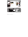
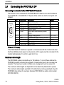
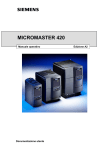
Interfaces of the CU240S Control Units.
The interfaces are shown in the figure below.
Common Interfaces
The CU240S Control Units have a number of interfaces such as terminals, general I/O
DIP switches or MMC interface and Option Port in common.
Different Interfaces
● 9-pole SUB D connector as communication interface for
– CU240S (USS via RS485),
– CU240S DP (PROFIBUS DP)
– CU240S DP-F (PROFIBUS DP)
● Failsafe terminals for
– CU240S DP-F: Two paired fail-safe digital inputs,
– CU240S PN-F: marked with a "*" in the figure
● DIP switches to set the PROFIBUS address
– CU240S DP (PROFIBUS DP)
– CU240S DP-F (PROFIBUS DP)
● RJ45 connectors as communication interface
– CU240S PN: Two connectors
– CU240S PN-F: Two connectors
8
CU240S
Getting Started, 10/2007, A5E01301803B AA
Installation
2SWLRQ3RUW
3&&RQQHFWLRQ.LW
RSWLRQDO
(1&$3
(1&$1
(1&%3
(1&%1
(1&=3
(1&=1
9(QFRGHU
VXSSO\
(QFRGHU$
WHUPLQDWLRQ
(QFRGHU%
WHUPLQDWLRQ
(QFRGHU=
WHUPLQDWLRQ
352),%86$GGUHVV',3VZLWFK RQO\&86'3'3)
%LW
%LW
%LW
2))
%LW
21
;3
YLD30,)
3RZHU0RGXOH
$,
9(QFRGHU
VXSSO\
2))
$,
21
', )',$
', )',%
', )',$
)',%
%23
%DVLF2SHUDWRU3DQHO
*HQHUDO,2',3VZLWFKHV
%LW
9
9
(1&
6XSSO\
00&
%LW
9
9
$,
$,
',
',
',
',
89
$,
$,
$2
$2
37&
37&
',
',
1&
12 '2
&20
12
'2
&20
1&
12 '2
&20
$2
$2
89
%LW
&86
&86'3
&86'3)
;3
&8631
&8631)
)DLOVDIHYHUVLRQVLQEUDFNHWV
CU240S
Getting Started, 10/2007, A5E01301803B AA
9
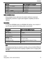
Installation
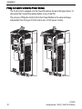
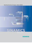
Fitting the Control Unit to the Power Module
The Control Unit is snapped onto the Power Module as shown in the figure below. To
disconnect the CU push the release button on top of the PM.
The process of fitting the Control Unit to the Power Module is the same technique
independent from the type of G120 control unit or G120 power module.
10
CU240S
Getting Started, 10/2007, A5E01301803B AA
Installation
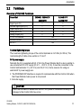
2.2
Terminals
Overview of CU240S Terminals
Control Unit
CU240S / CU240S DP
CU240S DP-F
CU240S PN
CU240S PN-F
9
-3
2
2
6
2
3
2
2
Digital Inputs (DI)
Fail-safe digital Inputs (FDI)
Digital Outputs (DO)
Analog Inputs (AI)
Analog Outputs (AO)
PTC/KTY84 interface
Encoder interface
Ext. 24 V
Yes
1, TTL or HTL
Yes
Terminal tightening torque
The maximum tightening torque of the control terminals is 0.25 Nm (2.2 lbf.in). The
nominal length of cable cross-section is 1.5 mm2.
24 V power supply
Normally the CU is supplied with 24 V from the Power Module. But it is also possible to
use an external DC 24 V supply (20.4 V … 28.8 V, 0.5 A). It must be connected to the
Control Unit terminals 31 (+ 24 V In) and 32 (0 V In). Some reasons for using an
external 24 V power supply are:
● The PROFIBUS DP interface is required to communicate with the Control Unit when
the Power Module mains power is not present
● Encoder supply
CAUTION
Care must be taken to ensure that the 24 V DC power is connected correctly or
damage to the Control Unit may occur.
CU240S
Getting Started, 10/2007, A5E01301803B AA
11
Installation
Note
If the CU is externally powered with 24 V DC but the power module is disconnected
from the mains supply, the faults F0001 … F0028 are not generated.
Cable length for 24 V DC supply and I/O cables
The maximum cable length on the 24 V DC supply and I/O cables connected to the CU
must not exceed 10 m (32.8 ft).
Use of unscreened cables is possible, however we recommend the use of screened
cables, in order to fulfill the EMC requirements for the CE marking and fail-safe
products (CU240S DP-F, CU240S PN-F).
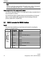
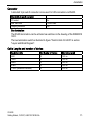
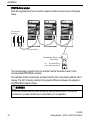
2.3
SUB D connector for RS485 interface
Socket
The Control Units CU240S have a 9-pin female sub-D socket for connecting the
inverter via an RS485 interface.
12
Pin
Designation
Description
1
2
3
4
5
6
7
8
9
X
RS485P
0V
RS485N
Screen
(casing)
Unused
Unused
Receive- and transmit signal (+)
Unused
Ground reference
Unused
Unused
Receive- and transmit signal (-)
Unused
Potential equilisation
CU240S
Getting Started, 10/2007, A5E01301803B AA
Installation
Connector
A standard 9 pin sub-D connector can be used for USS connection via RS485.
Standard 9 pin sub D connector
PG socket
Max. baud rate
Outgoing cable unit
No
115200 baud
180°
Bus termination
The RS485 termination can be activated via switches on the housing of the SINAMICS
G120.
The bus termination switch is illustrated in figure "Control Units CU 240S" in section
"Layout and Block Diagram".
Cable Lengths and number of devices
Baudrate in bit/s
Max Number of Devices
Max Cable Length
9600
19200
38400
57600
115200 (maximum baudrate)
32
32
32
32
30
1200 m
1200 m
1200 m
1200 m
1000 m
CU240S
Getting Started, 10/2007, A5E01301803B AA
13
Installation
2.4
Connecting the PROFIBUS DP
Connecting the Inverter to the PROFIBUS DP network
The inverter is to be connected to the PROFIBUS DP network via a sub-D socket on
the CU240S DP or CU240S DP-F. The pins of the socket are short-circuit-proof and
isolated.
Pin
Designation
Description
1
2
3
4
5
Shield
U0V
RxD/TxD-P
CNTR-P
DGND
6
7
8
9
Case
VP
U24V
RxD/TxD-N
Cable shield
Ground connection
Isolated and user supply reference
Receive/send data P (B/B')
Control Signal
PROFIBUS data reference potential
(C/C')
Supply voltage positive
Isolated user supply +24 V @ 100 mA
Receive/send data N (A/A')
Not assigned
Cable shield
Range
RS485
TTL
5 V ± 10 %
RS485
External 24 V supply
If the PROFIBUS DP interface is required to communicate with the Control Unit when
the Power Module mains power is not present, a 24 V supply must be connected to the
Control Unit terminals 31 (+ 24 V In) and 32 (0 V In).
Maximum cable length
The PROFIBUS system can handle up to 126 stations. To run all these stations the
PROFIBUS system is divided into segments. All segments have to be connected via
repeater. The maximum number of stations on any segment must not exceed 32.
The maximum cable lengths are dependent on the baud rate (transmission speed).
The maximum cable lengths specified in the table below can be guaranteed only with
PROFIBUS bus cables (for example, Siemens PROFIBUS bus cable, order number
6XV1830-0EH10).
14
CU240S
Getting Started, 10/2007, A5E01301803B AA
Installation
Baud rate
Max. cable lengths for one segment
9.6 kbaud … 187.5 kbaud
1000 m (3280 ft)*
500 kbaud
400 m (1312 ft)*
1.5 Mbaud
200 m (656 ft)*
3 Mbaud … 12 Mbaud
100 m (328 ft)*
∗ Repeaters can be installed to increase the length of a segment.
Cable installation rules
During installation the bus cable must not be twisted, stretched or compressed.
Supplementary constraints as regards electromagnetic compatibility must also be
observed.
Connectors
To connect the PROFIBUS cable to the PROFIBUS DP interface, a bus connector of
one of the types described in the following table is recommended.
Order Number
6GK1 500-0FC00 / 6GK1 500-0EA02
PG socket
Max. baud rate
Terminating resistor
Outgoing cable unit
Interfaces
PROFIBUS nodes
PROFIBUS bus cable
Connectable PROFIBUS cable diameter
No
12 Mbaud
On/Off switch
180°
9-pin sub D socket
4 modular terminals for wires up to 1.5 mm2
8 ± 0.5 mm
Note
We recommend only these two connectors since they can be used without difficulty for
all SINAMICS G120 models and are completely compatible in terms of outgoing cable
unit angle.
CU240S
Getting Started, 10/2007, A5E01301803B AA
15
Installation
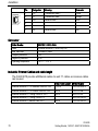
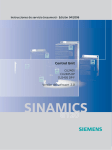
PROFIBUS terminator
Each bus segment must have a resistor network at both ends as shown in the figure
below.
3/&FRQQHFWRU
WHUPLQDWHG
5
5
RQ
5
RQ
RII
RQ
RII
RII
$ % $ %
$ % $ %
)URQWYLHZLQYHUWHU
%XVWHUPLQDWLRQVZLWFKRQ
WKHFRQQHFWRU
8S %XVWHUPLQDWLRQRQ
'RZQ%XVWHUPLQDWLRQRII
5
RQ
RII
$ % $ %
The bus termination resistor has to be activated via the terminator switch on the
recommended PROFIBUS connector
The switches of the bus terminator provides both the 220 Ω termination and the 390 Ω
biasing. The 390 Ω biasing maintains the potential difference between the signals in
the PROFIBUS network cables.
WARNING
It must be ensured that any node, where the biasing components of the bus are
connected, is powered at all times in which the bus is in operation.
16
CU240S
Getting Started, 10/2007, A5E01301803B AA
Installation
Removing a bus connector
You can remove the bus connector with looped-through bus cable from the
PROFIBUS DP interface at any time without interrupting the data exchange on the
bus. Only the final node must be terminated.
R
on
off
A1 B1 A2 B2
2.5
R
on
off
A1 B1 A2 B2
Connecting a CU240S PN / CU240S PN-F via
PROFINET
Socket
The Control Units CU240S PN and CU240S PN-F are equipped with a two port
ethernet switch, carried out as RJ45 female sockets. Connection to optical nets is
achieved by using switches with both electrical and optical ports, the drive is then
connected to an electrical port. Therefore, no power supply for an external
electrical/optical inverter is provided.
The assembly of the SIMATIC NET Industrial Ethernet FastConnect RF45 Plug 180 is
described in the product information "Assembly Instructions for SIMATIC NET
Industrial Ethernet FastConnect RJ45 Plug". For downloading this document, refer to:
http://support.automation.siemens.com/WW/view/en/23175326/130000
CU240S
Getting Started, 10/2007, A5E01301803B AA
17
Installation
Pin
Designation
Meaning
Core color
1
2
3
4
5
6
TX+
TX
RX+
RX-
Transmission data +
Transmission data Receiver data +
Yellow
Orange
White
Receiver data -
blue
Connector
Order Number
6GK1901-1BB10-2Ax0
Label
Max. baud rate
Outgoing cable unit
Degree of protection
Operating temperature
Industrial Ethernet FC RJ45 Plug 180
100 Mbit/s; Cat5e
180°
IP20
-20 °C … +70 °C
Industrial Ethernet Cables and cable length
The CU240S PN provides all Ethernet-cables. As well 1:1 cables as crossover-cables
can be used.
Industrial Ethernet FC TP Standard Cable GP 2 x 2
Industrial Ethernet FC TP Flexible Cable GP 2 x 2
Industrial Ethernet FC Trailing Cable GP 2 x 2
Industrial Ethernet FC Trailing Cable 2 x 2
Industrial Ethernet FC Marine Cable 2 x 2
18
Max. Cable Length
Order Number
100 m
85 m
85 m
6XV1840-2AH10
6XV1870–2B
6XV1870–2D
6XV1840–3AH10
6XV1840–4AH10
85 m
CU240S
Getting Started, 10/2007, A5E01301803B AA
Installation
Cable installation rules
Screening
The screen of the PROFINET cable must be connected with the protective earth, using
a screen clamp on the PROFINET cable which must make 360° contact earth. The
solid copper core must not be scored when the insulation is removed from the core
ends.
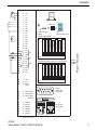
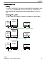
Connecting the IO supervisor
You can go online with STARTER in a number of ways, which are illustrated below:
(6
67$57(5
31
(6
67$57(5
31
(6
67$57(5
3%
352),1(7
&RQWUROOHU
6,1$0,&6
*
3%
352),1(7
352),1(7 866
352),1(7
&RQWUROOHU
6,1$0,&6
*
3%
352),1(7
352),1(7 866
352),1(7
&RQWUROOHU
6,1$0,&6
*
3%
352),1(7
CU240S
Getting Started, 10/2007, A5E01301803B AA
352),1(7 866
19
Check List
Note
Pay attention to the following restrictions:
• A ring-type topology is not permissible.
• SINAMICS does not support routing from PROFIBUS to PROFINET and vice versa.
3
Check List
Installation check list
Before power is applied to the inverter/motor system, the following checks should be
performed:
Check that:
1
2
3
4
5
6
7
8
9
10
11
12
13
14
20
✓
The environmental conditions conform to the inverter/motor specifications
The inverter and the motor are securely mounted
The inverter and motor are correctly installed with adequate cooling provision
The motor and the application/equipment are ready to start, i.e. safe state - motor can
rotate
The inverter is correctly earthed/grounded
The input power (supply) voltage matches the inverter's nominal input voltage
The input power (mains) fuses are the correct type and installed correctly
The motor connections are connected to ensure the correct direction of rotation of the
motor at start-up
The motor and mains connections are connected and tightened to the required
specification
The motor connections are not reversed - the motor will start but serious damage may
occur to the connected equipment
The motor cable is routed away from other cables
The control connections are connected and tightened to the required specification
No tools or other objects that can cause damage to the system are present
The inverter is the only power source to the motor
CU240S
Getting Started, 10/2007, A5E01301803B AA
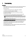
4
Commissioning
Description
When shipped from the factory the G120 inverter (control unit and power module) must
not be operated before a commissioning of the inverter has been performed.
This can be done via:
● downloading a valid parameter set from an MMC, BOP or STARTER
● performing a commissioning via BOP or STARTER
For a successful operation of the inverter-motor combination, the following
prerequisites must be fulfilled:
● The rated inverter current is at least as great as the rated current of the motor.
● The power range of the inverter matches the power range of the motor.
Note
Commissioning of fail-safe functions is not described in this manual. Please refer to
Operating Instructions and Function manual.
Commissioning with the Getting Started Guide
Commissioning in the Getting Started Guide is described using STARTER via PC
Connection Kit. For other commissioning modes please refer to the Operating
Instructions of the Control Module.
The STARTER software uses a series of wizards and masks to guide the user through
the commissioning procedures for the inverter.
CU240S
Getting Started, 10/2007, A5E01301803B AA
21
Commissioning
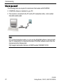
What do you need?
The following items are required to commission the Inverter with STARTER:
● STARTER software is installed on your PC
● The inverter is connected to the PC via the PC connection cable - order number:
6SL3255-0AA00-2AA0
Note
For commissioning the inverter you can use the STARTER software, delivered with
the PC Connection Kit or download the latest STARTER software version from the
internet under the following link:
http://support.automation.siemens.com/WW/view/de/10804985/133100
22
CU240S
Getting Started, 10/2007, A5E01301803B AA
Commissioning
4.1
Create a STARTER Project
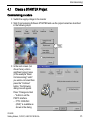
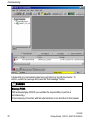
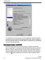
Commissioning procedure
● Switch the supply voltage to the inverter
● Start Commissioning Software STARTER and use the project wizard as described
in the following steps
● In the next screen (not
shown here), enter a
significant project name
(in the example "Basic
Commissioning)" and if
you want a comment then
press the "Continue"
button. The following
dialog box will appear.
Press "Change and test
..." button to set the
PG/PC interface.
– If "PC COM-Port
(USS)" is available as
shown in the dialog
CU240S
Getting Started, 10/2007, A5E01301803B AA
23
Commissioning
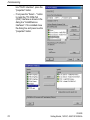
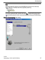
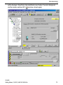
box "PG/PC interface", press the
"properties" button.
– If not press the "Select ..." button
to install the "PC COM-Port
(USS)" interface as shown in the
dialog box "Install/Remove
Interfaces". If it is installed close
the dialog box and press now the
"properties" button.
24
CU240S
Getting Started, 10/2007, A5E01301803B AA
Commissioning
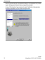
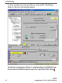
● Setting properties of the COM port
Via this dialog box, you set the com
interface (COM1, COM2, COM3) and
the Baud rate (default 38400). To find
out the right values, select e.g. COM1
and press the "Read" button. If "???"
is displayed in the Baud rate test area
select another com interface. In case
of the right interface a value will be
displayed, that must be chosen via the
"Baud rate" select box. In addition,
select "Automatic mode" under the tab
"RS485". Quit with "OK" brings you
back to the dialog box "Set PG/PC
interface". Quitting again with "OK"
brings you to the step "Insert drives" of
the Project Wizard.
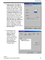
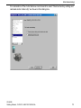
● In this dialog you can
enter a name for your
inverter - in this case
"SINAMICS_G120_
CU240S" (no blanks or
special characters), then
press "Continue" and
close the following
summary dialog via the
"Complete" button.
CU240S
Getting Started, 10/2007, A5E01301803B AA
25
Commissioning
4.2
Going Online with the Inverter
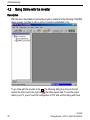
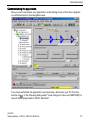
Description
With the above described procedure the project is created and the following STARTER
dialog appears, but there is still no online connection established so far.
. The following dialog box shows in the left
To go online with this inverter press
column the online and in the right column the offline saved data. To load the online
data to your PC, press "Load HW configuration to PG" and end the dialog with close.
26
CU240S
Getting Started, 10/2007, A5E01301803B AA
Commissioning
4.3
Start Commissioning
Description
With closing the last dialog from the "Going Online Section" the "Offline mode" at the
very down in the dialog box changes to "Online mode" and in case of first
commissioning the message F00395 appears.
CU240S
Getting Started, 10/2007, A5E01301803B AA
27
Commissioning
It states that no commissioning has been performed so far with the inverter. To
confirm, select the message and press the "Acknowledge" button.
WARNING
Message F0395
With acknowledging F00395 you overtake the responsibility to perform a
commissioning.
Commissioning of inverters with fail-safe functions is not described in this manual.
28
CU240S
Getting Started, 10/2007, A5E01301803B AA
Commissioning
Note
Information about the symbols used in STARTER can be found in the online help.
Press <shift><F1> and then click at the requested symbol. E.g.
If you have confirmed F0395, open the drive unit (
), double-click the drive object
( ) and start the wizard for basic commissioning from the following STARTER dialog.
Perform Commissioning Start dialog:
CU240S
Getting Started, 10/2007, A5E01301803B AA
29
Commissioning
Now you can select the basic commissioning settings for your application via pull-down
menus. With pressing "Continue" button you jump to the next item.
In case of "Drive functions" we recommend to select "Identification of all parameters
inclusive the saturation curve" as shown in the figure below:
30
CU240S
Getting Started, 10/2007, A5E01301803B AA
Commissioning
For calculation of the motor data we recommend to select "Restore factory setting and
calculate motor data only" as shown in the dialog box.
CU240S
Getting Started, 10/2007, A5E01301803B AA
31
Commissioning
The basic commissioning wizard ends with the following dialog:
To complete basic commissioning, the motor data identification, selected during basic
commissioning must be performed via switching on the inverter. This can be done via
the chosen command source (e.g. terminals, BOP or communication) or via STARTER
as shown in the dialog box below.
Motor Data identification via STARTER
First click "Control panel" to open the dialog, then press "Assume control priority"
(when connected via PC connection Kit, select BOP link (RS232) (the "assume-button"
changes to "Return") and select "Enables". Now the ON and OFF buttons get active.
Press the ON button start the Motor data identification. While Motor data identification
is active, the -button is disabled and in the alarm 541 "Motor Identification active"
32
CU240S
Getting Started, 10/2007, A5E01301803B AA
Commissioning
will be displayed. Once Motor data identification has finished, the alarm disappears
and the inverter switches OFF ( becomes colored again).
CU240S
Getting Started, 10/2007, A5E01301803B AA
33
Commissioning
To set the command source back press "Give up control priority!" in the following
dialog box. Take care of the warnings displayed.
Now the basic commissioning is finished. To save the settings in the EEPROM of your
inverter, select the SINAMICS project and press the "Copy RAM to ROM" button
.
34
CU240S
Getting Started, 10/2007, A5E01301803B AA
Commissioning
Commissioning the application
Now you can commission your application via the dialog boxes of the drive navigator
or via the functions in the navigation area.
If you have performed the application commissioning, disconnect your PC from the
inverter via . In the following dialog select "save changes to drive unit (EEPROM), to
current offline project and to PG/PC hard disk".
CU240S
Getting Started, 10/2007, A5E01301803B AA
35
Commissioning
This selection performs in addition to disconnecting the PC form the inverter the
following steps:
: saves project on your PC
: saves drive settings on your PC (Upload)
: Saves data from inverter RAM to EEPROM
4.4
Factory reset
Description
With a factory reset a defined initial state of all of the inverter parameters can be reestablished.
To perform a factory reset with STARTER, the inverter must be in the online mode. If it
is offline, perform "connect to target system" ( )
The factory reset is performed in the following steps:
Select the drive unit in the navigation tree (
● Click the factory reset icon (
)
).
Note
When resetting the parameters to the factory setting, the communications memory
is re-initialized. This means that communications are interrupted for the time it takes
to perform the reset.
36
CU240S
Getting Started, 10/2007, A5E01301803B AA
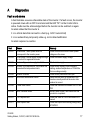
A
Diagnostics
Fault s and alarms
A fault indicates a severe unfavorable state of the inverter. If a fault occurs, the inverter
is powered down with an OFF2 command and the LED "SF" on the Control Unit is
active. Faults must be acknowledged before the inverter can be switched on again.
An alarm states that the inverter is
● in a critical state that can lead to a fault (e.g. A0501 current limit)
● in an extraordinary temporarily state e.g. motor data identification
An alarm requires no reaction
Fault
Cause
Remedy
F00001
Overcurrent - Motor power does not
correspond to the inverter power
Overvoltage - mains supply voltage too high
or motor is in regenerative mode.
Undervoltage - mains supply has failed
Inverter over temperature - the inverter has
exceeded the temperature limits
Check that the motor and inverter power
ratings are the same.
Check the mains supply voltage
F00002
F00003
F00004
F00005
F00041
Inverter overload
Motor data identification failure
F00052
Power stack failure
F00062
MMC contents invalid
F00070
PLC setpoint fault
F00071
USS setpoint fault
CU240S
Getting Started, 10/2007, A5E01301803B AA
Check mains supply
Check motor loading, pulse frequency
setting, ambient temperature or if fitted the
fan is working correctly.
Check motor power and load cycle
check that the motor is connected to the
inverter correctly and that the motor data
entered is correct.
Check the connections between the CU and
PM.
Recopy data to MMC and ensure that the
process is completed.
Check the value of P2040 and ensure it is
correct
Check and improve monitoring timing using
STARTER
37
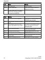
Diagnostics
Fault
Cause
Remedy
F00072
F00090
USS setpoint fault
Encoder feedback loss
Check USS master
Check that the encoder is installed and
commissioned correctly.
F0395
The fault occurs after a CU/PM swap or
startup clone. It can also be cause by a
faulty read from the EEPROM.
Alarm
Meaning
A0700
Correct the PROFIBUS configuration
A0702
Check connector, cable and PROFIBUS
master.
Check setpoints from the PROFIBUS
master. Switch SIMATIC CPU to "RUN".
A0703
A0704
Activate internode transmitter.
A0705
A0706
A0710
None (fault is with the inverter).
None diagnostic parameter r2041.
Communication interface on Control Unit
may be broken.
Check P0918 address and P2041.
A0711
38
The parameter or configuring settings by the
PROFIBUS master are invalid.
The link to the PROFIBUS is interrupted.
No setpoints or invalid setpoints (control
word = 0) are being received from the
PROFIBUS master.
At least one configured internode transmitter
is not yet active, or has failed.
No actual values received from inverter.
PROFIBUS DP software error.
Inverter has detected failure of PROFIBUS
communications link.
Invalid value of PROFIBUS parameter.
CU240S
Getting Started, 10/2007, A5E01301803B AA
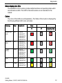
Diagnostics
Status display via LEDs
The SINAMICS G120 inverters provide multiple functions and operating states which
are indicated via LEDs. The LED for fail-safe inverters are not described in this
manual.
Colors
The colors of the LEDs are self explanatory. The Status of the inverter is displayed by
the following different LED colors and states:
Meaning
Color
Available in
State
on
sample fault
(SF)
Red
Bus failure
(BF)
Red
Ready
(RDY)
Green
LNK
Green
ACT
Yellow
off
Temporary state
(flashing 0.5 Hz)
CU240S
CU240S DP
CU240S DP-F
CU240S PN
CU240S PN-F
CU240S DP
CU240S DP-F
CU240S PN
CU240S PN-F
CU240S
CU240S DP
CU240S DP-F
CU240S PN
CU240S PN-F
CU240S PN
CU240S PN-F
CU240S PN
CU240S PN-F
CU240S
Getting Started, 10/2007, A5E01301803B AA
39
Diagnostics
LED description
● System-Fault LED (SF)
The system-fault LED indicates a general system error either software or hardware
related.
● Ready LED (RDY)
The ready LED indicates whether the inverter is ready to run.
This LED does not indicate whether the drive is running or not.
● Bus-Failure LED (BF)
The Bus-failure LED indicates if any bus failure occurred. A bus failure can be
characterized as corrupted communication (e.g. a frame of the PROFIBUS) due to
signaling problems on the bus itself.
The Bus-failure LED indicates the following states:
– Bus-failure LED off: no Bus failure
– Bus-failure LED on: no connection to the DP-Master (searching for baud rate)
– Bus-failure LED flashing 0.5 Hz: I/O device is not configured or is wrongly
configured (baud rate found, no data exchange).
● LNK: Shows that link via X20 P1 / X20 P2 is established
● Act: Shows active data transfer via X20 P1 / X20 P2
40
CU240S
Getting Started, 10/2007, A5E01301803B AA