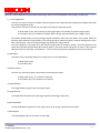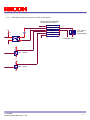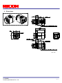
1
GigE Vision
UXGA Monochrome CCD Camera
FV-G200B1
Product Specifications
RICOH COMPANY, LTD.
FV-G200B1
Product Specifications Rev. 1.03
1/14
Copyright & Disclaimer
Sensor Technology Co., Ltd. (DBA Sentech) believes the contents and specifications of its website, catalog, documentation
and ads are correct; however, Sentech provides no representation or warranty regarding such information or product(s)
contained therein. It is requested that Sentech be given appropriate acknowledgement in any subsequent use of such work
by a third party.
While every effort has been made to ensure that the details contained in Sentech’s website and all documentation are
correct and up-to-date, Sentech assumes no liability, legal or otherwise for any errors in listings, specifications, part
numbers, process, software or model applications. Sentech reserves the right to change specifications, product
descriptions, product quality, pricing and application at any time without prior written or oral notice. Any party using such
information assumes all risk for any and all damaged caused to themselves, a third party and/or property by virtue of
incorrect information and/or failure of these products. By installing and/or using a Sentech software development kit or
other similar product and/or information obtained from Sentech’s website, catalog, documentation or ads, you hereby
accept and understand these stated terms and conditions.
FV-G200B1
Product Specifications Rev. 1.03
2/14
Table of Contents
1
Safety / Product Precautions ...............................................................................................................................4
2
Electronic / Mechanical / Environmental Specifications...................................................................................6
2.1
3
Spectral Sensitivity Characteristics......................................................................................................................... 8
Connector Specifications .....................................................................................................................................9
3.1
RJ45 Connector ...................................................................................................................................................... 9
3.2
DC Iris Lens Connector ........................................................................................................................................ 10
3.3
Power-I/O connector ............................................................................................................................................. 10
3.3.1 Equivalent Circuit for the Input Pin of the I/O Connector .................................................................................. 12
4
Dimensions ..........................................................................................................................................................13
FV-G200B1
Product Specifications Rev. 1.03
3/14
1
Safety / Product Precautions
Safety Precautions
CAUTION
RISK OF ELECTRIC SHOCK
DO NOT OPEN
For U.S.A.
!
Warning:
CAUTION:
TO REDUCE TH E RISK OF EL ECTRIC SHOCK, DO N OT
REMOVE COVER (OR BACK). NO USER SERVICEABLE
PARTS INSIDE.
REFER SERVICING TO QUALIFIED SERVICE PERSONNEL.
This equipment generates and uses radio frequency energy and if
not installed and used properly, I.e., in strict accordance with the
instruction manual, may cause harmful interference to radio
communications. It has been tested and found to comply with the
limits for a Class A computing device pursuant to Subpart J of Part
15 of FCC Rules, which are designed to provide reasonable
protection against such interference when operated in a commercial
environment.
For Canada
The li ghtning flash with arrowhea d
symbol, within an equilateral triangle,
i s i nt ended t o alert the use r t o the
pre sence of uni nsulated “dangerous
v o l ta g e ” w i th in t h e p r o du c t ’ s
enclosure t hat may be of suffici ent
ma gnitude t o c onst i tute a ri sk of
electric shock to persons.
Warning:
The exclama ti on point wi t hi n a n
equilateral triangle is intended to alert
the user to the presence of import ant
operating and maintenance (servicing)
i n st r u c ti o ns in t h e l i te r a t u r e
accompanying the appliance.
WARNING:
This digital apparatus does not exceed the Class A limits for radio
noise emissions from digital apparatus set out in the Radio
Interference Regulations of the Canadian Department of
Communications.
TO PREVENT FIRE OR SHOCK HAZARD, DO NOT EXPOSE
THIS APPLIANCE TO RAIN OR MOISTURE.
Product Precautions
Handle the camera with care. Do not abuse the camera. Avoid striking or shaking it. Improper handling or
storage could damage the camera.
Do not pull or damage the camera cable.
During camera use, do not wrap the unit in any material. This will cause the internal temperature of the
unit to increase.
Do not expose the camera to moisture, or do not try to operate it in wet areas.
Do not operate the camera beyond its temperature, humidity and power source ratings.
While the camera is not being used, keep the lens or lens cap on the camera to prevent dust or
contamination from getting in the CCD or filter area and scratching or damaging this area.
Do not keep the camera under the following conditions:
In wet, moist, and high humidity areas
• Under hot direct sunlight
• In high temperature areas
• Near an object that releases a strong magnetic or electric field
• Areas with strong vibrations
Apply the power that satisfies the requirements specified in this document to the camera.
Use a soft cloth to clean the camera. Use pressured air spray to clean the surface of the glass. DO not
scratch the surface of the glass.
FV-G200B1
Product Specifications Rev. 1.03
4/14
The camera is a general-purpose electronic device; using the camera for the equipment that may
threaten human life or cause dangers to human bodies directly in case of failure or malfunction of the
camera is not guaranteed. Use the camera for special purposes at your own risk.
FV-G200B1
Product Specifications Rev. 1.03
5/14
2
Electronic / Mechanical / Environmental Specifications
Product
Electronic
Specifications
FV-G200B1
Imager
1/1.8” Interline UXGA monochrome progressive CCD: ICX274AL
Total Picture Elements
Active Picture Elements
Cell Size
1688 (H) x 1246 (V)
UXGA: 1624 (H) x 1236 (V)
4.4 (H) x 4.4 (V) µm
Scanning System
Vertical Frequency
(Frame Rate)
Progressive
15.31668 Hz at full resolution
0.29261 to 61.26674 Hz adjustable via the communication
(Frame rate depends on the AOI setting)
Maximum frame rate (61.26674 Hz) is when vertical resolution AOI setting is 232.
Horizontal Frequency
19.1761 kHz
Pixel Frequency
36.8181 MHz
Noise
Level
@ 8bit output
≤ 3 Digit (Gain 0 dB)
@ 10bit output
≤ 12 Digit (Gain 0 dB)
@ 12bit output
Minimum Scene Illumination
Sync. System
≤ 48 Digit (Gain 0 dB)
0.16 Lux at F1.2, 15.31668 Hz
Internal
Video Output Format
Digital 8, 10 or 12 bit Raw Data or RGB 8 bit
Interface
IEEE802.3 (1000BASE-T)
Protocol
GigE Vision® 1.2 and GenICam™ 2.0 compliant
Preset continuous mode: 1 useconds to 16,777,215 useconds
Exposure Time
Preset trigger mode: 1 useconds to 16,777,215 useconds
Pulse width mode: 1 useconds to Unlimited
ALC
Auto iris lens, electronic iris and AGC (ON/OFF)
Gain
0 to 20.4 dB
Gamma
Gamma 1.0 (Factory default) or uploadable gamma table
AOI Function
Programmable AOI setting via the communication
Smear Reduction
Selectable ON/OFF via the communication
Operational Mode
Free-run, Edge preset trigger, Pulse width trigger (unlimited long exposure)
Communication
UART Communication through Ethernet port
I/O
One opt-isolated input and two open-collector outputs
Auto IRIS Lens Control
DC IRIS control input with video level target, peak/average and zone weight settings
via the communication
Power
Mechanical
Dimensions
Specifications
Optical Filter
Input Voltage
Consumption
Optical Center Accuracy
Material
+10.8 to +26.4 Vdc
Less than 5.00 W
35 (W) x 35 (H) x 50.8(D) mm excluding connectors
No Filter
Positional accuracy in H and V directions: +/- 0.3 mm
Rotational accuracy of H and V: +/- 1.5 deg.
Aluminum (AC)
Lens Mount
C mount
Connectors
RJ45 connector
Power-I/O connector: HR10A-7R-6PB (Hirose) or equivalent
DC IRIS lens connector: M1951 (EMUDEN) or equivalent
Camera Mount Screws
Two 1/4” Tripod screw holes: (One on each top and bottom plate),
Twelve M4 screws holes: (Four on each top and bottom plate, two on each side plate)
FV-G200B1
Product Specifications Rev. 1.03
6/14
Weight
Approximately 120 g
Product
FV-G200B1
Environmental
Specifications
Environmental Temperature -5⁰C
Minimum
Operational
Camera housing temperature (top plate) shall not exceed 65⁰C
Temperature
Maximum
(This corresponds to an environmental temperature of approximately 35⁰C)
Environmental Temperature: -30⁰C to 65⁰C
Storage temperature
Vibration
20Hz to 200Hz to 20Hz (5min./cycle), acceleration 10G, 3 directions 30 min. each
Shock
Standard Compliancy
RoHS
Acceleration 38G, half amplitude 6ms, 3 directions 3 times each
EMS: EN61000-6-2, EMI: EN55011, FCC PART15 subpart B classA
RoHS Compliant
Note: Please use this camera in surrounding temperature conditions that are less than 35⁰C or in conditions where the
camera’s top case plate is less than 65⁰C.
When the camera is used in surrounding temperatures that exceed 35⁰C, please make sure that the camera is set up
to properly radiate heat (maintaining the camera’s top case plate’s temperature to be less than 65⁰C).
Taking these steps will maintain the heat rating of the electronic components of the camera.
FV-G200B1
Product Specifications Rev. 1.03
7/14
2.1
Spectral Sensitivity Characteristics
1
Relative Response
0.8
0.6
0.4
0.2
0
400
500
FV-G200B1
Product Specifications Rev. 1.03
600
700
Wave length [nm]
800
900
1000
8/14
3
Connector Specifications
DC Iris Lens Connector
RJ45 Connector
Power-I/O Connector
3.1
RJ45 Connector
This product is NOT a PoE type. Apply power (+10.8 to +26.4Vdc) ONLY through the I/O connector.
Pin Assignment:
LED Information:
Pin No.
Signal Name
1
2
3
4
5
6
7
8
TA+
TATB+
TC+
TCTBTD+
TD-
The camera is powered-on
Green LED
Yellow LED
Status
Green Light ON
Orange Light ON
Power ON
Green Light ON
Orange Light Blinking
1Gb Transferring
Light OFF
Orange Light Blinking
100 Mb Transferring
Green light: ON
Yellow light: Blinking
1 Gb Transferring
Green light: OFF
Yellow light: Blinking
100 Mb Transferring
Please use a 1Gb supported NIC, HUB and LAN cable. Check that the NIC and HUB being used is “1Gb
transferring”.
Damaging or mishandling the CAT5e cable may cause the transferring speed to change from 1Gb to 100Mb.
If this happens, please replace the CAT5e cable.
FV-G200B1
Product Specifications Rev. 1.03
9/14
3.2
DC Iris Lens Connector
M1951 (EMUDEN) or equivalent.
Pin Assignment
Pin No.
1
2
3
4
3.3
3 4
Signal Name
DAMPDAMP+
DRIVE+
DRIVE-
1 2
Power-I/O connector
HR10A-7R-6PB(Hirose)or equivalent
This connector is for the power supply (12Vdc) and input /output signals.
Use HR10A-7P-6S (Hirose) or equivalent for the cable side.
Pin Assignment
Pin No.
1
2
3
Signal Name
GND
I/O-1
I/O-2
IN / OUT
IN
OUT
OUT
4
TRG_In-
IN
5
TRG_In+
IN
6
POWER IN
IN
Voltage
0V
+3.3V LVTTL
+3.3V LVTTL
Low: Smaller than +1.0V (Opt. Isolated -)
High: +3.0 to +26.4V
(Opt. Isolated +)
*potential difference between TRG_In- and
TRG_In+
+10.8 to +26.4 Vdc
Output signals can be assigned through the camera setting communication.
(Device Code = 00H, Command = F0H and F1H)
IO Signal Patterns for Pin No.2 (I/O-1) and Pin No.3 (I/O-2)
Command No.
F0H[3..0]
F1[3]
F0H[7..4]
F1[4]
For I/O-1 (Pin No. 2)
For I/O-2 (Pin No.3)
0H
0H
(initial setting)
1H
Set Value
1H
Set Value
2H
2H
(initial setting)
3H
3H
4H
4H
5H
5H
6H
6H
7H-FH
7H-FH
-
FV-G200B1
Product Specifications Rev. 1.03
HR10A-7R-6PB (Hirose)
I/O-1 (Pin No.2) / I/O-2 (Pin No.3)
FrameTriggerWait
(initial setting for I/O-1)
UserOutput
ExposureActive
(initial setting for I/O-2)
TriggerAuxiliary
TriggerInternal
SensorReadOut
StrobeSignal
For Test Use Only
10/14
Note: I/O-1 can be assigned only by F0H[3..0] and F1[3], and I/O-2 can be assigned only by F0H[7..4] and F1[4].
1)
FrameTriggerWait
The user can check the camera condition (camera exposure and image output processing by the trigger signal with
this FrameTriggerWait signal).
This signal is LOW for the period from the trigger input signal to the image output.
a) High status (3.3V): No processing by the trigger signal. The camera accepts the trigger signal.
b) Low status (0V): The camera is exposed and the image output processes by the trigger signal.
The camera default setting is the input trigger signal is INVALID while at the low status of this signal. When the
exposure starts while the image output by the next trigger signal, please change the camera setting (Device code:
00H, Command No. :13H) to accept the trigger signal while the image outputs.
The noise appears on the image when the exposure begins while the image is output. The noise appears on the
image when the start exposure while the image is output. In this case, please change the “H reset” for the exposure
start mode (Device code: 00H, Command No. : 12H) to change the exposure start point to the next HD timing.
2) UserOutput
The status of the UserOutput signal can change with the “UserOutputValue”.
a) High status (3.3V)
b) Low status (0V).
3) ExposureActive
The user can check the exposure time with the ExposureActive signal.
a) High status (3.3V): The camera is exposing
b) Low status (0V): The camera is not exposed
4) TriggerAuxiliary
The TriggerAuxiliary signal is the input trigger signal.
5) TriggerInternal
The TriggerInternal signal is the input trigger signal with the trigger delay time.
6) SensorReadOut
The SensorReadOut signal is the FVAL signal, which is the image output period of the time.
7) StrobeSignal
The StrobeSignal signal is the strobe control signal.
FV-G200B1
Product Specifications Rev. 1.03
11/14
3.3.1
Equivalent Circuit for the Input Pin of the I/O Connector
HR10A-7R-6PB (HIROSE)
or equivalent connector
6
5
4
+3.3V
3
2
2.2K
1
6
1
4
3
+10.8 to +26.4V
Trigger_In+
Trigger_InIO_Out
IO_Out
GND
+3 to +26.4V
3 to 5mA
Trigger Signal
Customer GND
TOSHIBA TLP181
+3.3V
3
1K
2
RN1105MFV
1
TOSHIBA
+3.3V
3
1K
2
RN1105MFV
1
TOSHIBA
FV-G200B1
Product Specifications Rev. 1.03
12/14
4
Dimensions
Unit: mm
FV-G200B1
Product Specifications Rev. 1.03
13/14
Revision History
Rev
Date
Changes
1.00
1.01
2012/06/17
2012/06/18
1.02
2012/07/03
1.03
2012/08/25
Note
Initial Release
Updated
The output Signal “StrobeOut” is corrected to “StrobeSignal”
Updated
Document title
Electronic Specifications
Shutter Speed Exposure Time
The maximum value for the Exposure Time is corrected to 16,777,215
Equivalent Circuit for the Input Pin of the I/O Connector
Updated
Pin Assignment of Power-I/O Connector
RICOH COMPANY, LTD.
URL http://www.ricoh.com/fa_security/
FV-G200B1
Product Specifications Rev. 1.03
14/14