1
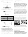
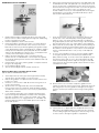
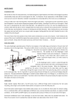
567441.A.4
ROTARY MOWER
SERVICING MANUAL
WWW.MASPORT.COM
Contents
CONTROLS
Engine Controls
Throttle Control Adjustment
Throttle Control Replacement
OPC Control Adjustment
Propulsion Controls
Drive Clutch
Drive Clutch Cable Adjustment (All models)
Drive Clutch Cable Replacement (Rear wheel drive models)
Drive Clutch Cable Replacement (Rotarola & front wheel drive models)
Drive Clutch Cable Replacement (Cone Clutch & Dog Clutch transmissions)
Variable Speed Propulsion Control
Variable Speed Propulsion Control Adjustment
Fitting a New Variable Speed Control Cable
Adjusting the Drive Belt (Single speed models)
Adjusting the Drive Belt (Variable speed models)
3
3
3
3
3
3
3
4
4
4
5
5
5
5
6
6
REPLACING DRIVE BELTS ON REAR WHEEL DRIVE MODELS
Preparation (Single and Variable Speed models)
Replacing Drive Belts On Single Speed Models
Replacing Drive Belts On Variable Speed Models
REPLACING DRIVE BELTS ON ROLLER DRIVE MODELS
7
7
7
8
9
Servicing Chains On Roller Drive Models
REPLACING DRIVE BELTS ON FRONT WHEEL DRIVE MODELS
REPLACING DRIVE BELTS ON SYNCHRO CLUTCH TRANSMISSION GEARBOX MODELS
REPLACING RETURN SPRING ON VARIABLE SPEED MODELS
REPLACING GEARBOX PULLEY ON VARIABLE SPEED MODELS
10
10
10
11
12
SLOW DOWN/SPEED UP KIT INSTALLATION
12
REAR AXLE UNIT – REAR WHEEL DRIVE MODELS
Description
Modified Pinions and Gears
Correct Pawl, Pinion and Cap Positions
Removing Rear Axle Units From Rear Wheel Drive Mowers
Dismantling the Rear Axle Unit
Notes on Flanged Steel Retaining Cups
Re-assembling the Axle Unit
13
13
13
13
13
14
15
15
REMOVING FRONT AXLES – ALL TYPES EXCEPT FRONT DRIVE
16
REMOVING REAR ROLLER UNITS
Dismantling the Rear Roller Unit
16
16
REMOVING FRONT DRIVE UNITS
Dismantling the Front Drive Unit
17
17
BLADES
Bar Blades
Quick Cut and Quad Cut Blades
Chipper Blades
Blade Replacement Torque Settings
17
17
17
18
18
CHIPPER CLOSER CABLE ADJUSTMENT
18
July 2013
NOTE:- All positional descriptions such as left, right, front, rear,
above and below refer to those places as seen by the operator
when standing behind the handle of the mower in its normal
grass-cutting orientation. Please note that these instructions
are to be read in conjunction with the Owner’s Manual for the
mower and the Engine Manufacturer’s Operator’s Manual for
the engine.
Controls
ENGINE CONTROLS
Some engines have a throttle control to allow the engine speed to be
varied as desired. Usually this control can be used also to stop the
engine, but, for some markets mowers are fitted with an Operator
Presence Control (OPC) that allows the engine to run only while the
OPC bail (a bar or hand-grips in front of the handle crossbar) is held
against the handle. If the operator releases the bail, the engine stops
immediately and the blade is braked to a stop.
Throttle Control Replacement
If the control is one of the types A, C and D shown on the previous
page, simply detach the control box from the handle, note where the
cable ties are fitted and cut them. After releasing the clamp screw
on the carburetor, the new cable can be fitted and held in place with
new cable ties. Clamp the control box onto the handle, refit the clamp
screw and adjust the cable position as detailed above.
To gain access to the control box for type B throttle controls (as fitted
to MSV models), remove the four screws from under the throttle
mount that hold the two halves of the mount onto the handle. The
top throttle mount can then be lifted clear of the handle. Remove the
M6x60 screw that fixes the control box to the top mount, note the
cable tie positions and cut the cable ties. After the clamp screw on
the carburetor has been removed, the throttle wire can be disengaged
from the carburetor lever. The old control box can then be withdrawn
from the top mount. Reverse this procedure to fit the new throttle
control. Take great care not to over-tighten the M6x60 screw that
holds the control box to the top mount as this would make movement
of the throttle lever very stiff. After fitting the cable wire into the
carburetor lever, re-assemble the two halves of the throttle mount
onto the handle, fit new cable ties, replace the clamp screw and
adjust the cable position as described above to give correct operation
of the engine.
Throttle Control Adjustment
Move the throttle control lever through its full range of travel.
OPC Control Adjustment
There are no adjustments provided on this control as it is a safety
feature that might then be over-ridden. When the OPC bail (see the
illustrations above) is held against the handle, the engine ignition can
function and the mower can be started. When the bail is released,
the primary winding of the ignition coil is shorted out, thus quenching
the ignition spark. At the same time, a brake pad contacts the engine
flywheel, bringing the blade to a rapid stop. If the OPC bail has
been damaged and twisted out of shape, the bail may contact the
handle before the ignition has been ‘switched on’. This is rare, but
straightening of the bail can provide a little extra control wire travel to
correct the fault.
This will move the lever on the carburetor from the “FAST” position
(when the wire is fully extended), to the ‘STOP’ position (when the
wire is fully retracted).
PROPULSION CONTROLS
Drive Clutch
The mower drive system is engaged by using the SP (Self Propulsion)
bail. See the illustrations on page 2. Lifting the SP bail, until it contacts
the handle, operates the clutch inside the gearbox. The clutch
is designed to be fully engaged or fully released. Any attempt to
reduce travel speed by only partially engaging the clutch will lead to
overheating of the gearbox. This will cause serious damage. For this
reason, it is important that the SP bail cable is adjusted to the correct
length to provide the necessary clutch engagement pressure.
If the engine is hard to start when cold, (and it does not have an
automatic choke), slacken off the cable clamp screw and slide the
cable outer sleeve forward a few millimetres. Tighten the clamp
screw again. On the other hand, if the engine does not stop when
the control lever is moved to the ‘STOP’ position, slacken the clamp
screw and slide the cable sleeve back a few millimetres. (Note:
Mowers with an OPC bail stop the engine using a different switch. See
OPC control adjustment, below). When the cable sleeve is positioned
correctly, the functions at both ends of the throttle wire travel should
both work correctly.
3
Drive Clutch Cable Adjustment (All models)
1. Confirm that the cable inner wire will move at least 26 mm when
the SP bail (see page 2) is moved from the clutch disengaged
(open) position to the engaged (closed) position against the
handle. Adjust the contour of the bail slightly if necessary to
achieve this wire stroke.
2. Wheel the mower backwards towards you while gradually
closing the SP bail, and note the position of the bail when extra
resistance to backwards movement indicates that the drive clutch
is just engaging. This extra resistance should occur when the SP
bail is half way between open and closed.
3. If the engagement point is incorrect, adjust it by rotating the
thumb-wheel on the anchor block at the top of the cable outer
sleeve. Rotating the wheel clockwise will move the clutch
engagement point nearer to the bail closed position, and anticlockwise will move it towards the bail open position.
4. Confirm that the adjustment is correct by re-testing the
engagement point.
5. Repeat this adjustment after 150 hours use of the mower or at
any time if the mower drive seems to be slipping.
5. Re-assemble the thumb-wheel and mounting block onto the top
end of the cable. Tip: To prevent the cable from slipping out of its
socket on the gearbox while re-fitting the rear axle assembly, take
the slack out of the wire and keep the outer cable in its socket by
fitting a temporary clamp on the wire against the top end of the
outer cable.
IMPORTANT: An incorrectly adjusted clutch cable, or using the
mower with the SP bail not fully against the handle will cause
clutch slippage, gearbox overheating and serious gearbox
damage.
Drive Clutch Cable Replacement (Rear wheel drive models)
1. Follow steps 1 to 11 detailed in REMOVING THE REAR AXLE
UNIT FROM THE MOWER (see below).
2. At the top end of the clutch cable, wind the thumb-wheel
adjuster until the thumb-wheel and the thumb-wheel block can
be removed completely from the threaded ferrule on the outer
cable.
6. Re-fit the rear axle assembly onto the mower by following the
dismantling steps in the reverse order.
7. Hook the ‘Z’ bend at the top of the cable wire into the SP bail,
and fasten the thumb-wheel block onto the handle. Fit the new
cable ties and remove the temporary clamp from the cable wire.
8. Adjust the cable for correct operation as described above in
DRIVE CLUTCH CABLE ADJUSTMENT.
3. The cable will now be small enough to pass through the aperture
in the housing and will then be completely free from the mower.
As the cable ties are removed, note their positions so that the
new ones can be fitted exactly in the same positions. This is
important to allow the handle to fold correctly.
4. Pass the top end of the new cable up through the housing
aperture. Attach its lower end to the gearbox by hooking the
cable spring onto the gearbox clutch lever, dropping the wire
through its slot and sliding the clutch outer cable into the socket
at the end of the slot.
Drive Clutch Cable Replacement (Rotarola & front wheel drive
models)
1. Remove the belt cover to gain access to the top of the gearbox.
2. Examine the path of the old cable, noting particularly where the
cable ties are fitted as this is important to ensure satisfactory
handle folding.
3. Withdraw the screw holding the cable thumb-wheel block to the
top of the handle. This will give enough slack in the cable to allow
the ‘Z’ shaped fitting at the top of the wire to be extracted from
the lug on the SP bail.
4. Working down the cable, cut the cable ties. At the gearbox, pull
the cable outer housing away from the gearbox to disengage it
from its locating hole.
5. Lift the cable wire up out of the slot in the gearbox and swing the
wire to the side so that the spring on the end of the cable wire
can be unhooked from the gearbox lever.
6. To fit the new cable, reverse the dismantling procedure.
7. After engaging the ‘Z’ fitting in the SP bail (take care to fit it from
the side of the SP bail lug that gives a straight run for the wire
into the cable housing), fasten the thumb-wheel block to the
handle and adjust the clutch action as detailed above.
4
Drive Clutch Cable Adjustment for models with the following
gearbox type fitted:
• Cone Clutch Transmissions, single and variable speed
• Dog Clutch Transmissions, single and variable speed
movement of the belt idler arm. If they do not match, either the top
or the bottom intended speed of travel will be unobtainable. This
matching is achieved by adjusting the length of the cable outer sleeve.
As explained above, the belt will not respond to downward travelspeed changes unless the engine is running. Do not engage the drive
clutch while making these adjustments, but make small changes and
then engage the drive to check the results. A better approach is to
remove the gearbox cover on the rear face of the mower housing
(3 screws), or the front of the mower in the case of front wheel drive
models. Then the adjustment can be made and verified without
engaging the drive clutch at all.
Please note models with the synchro gearbox fitted do not require
drive clutch cable adjustment, for more details refer to Synchro
Clutch Transmissions Gearbox page.
1. Confirm that the cable inner wire will move at least 26 mm when
the SP bail (see page 2) is moved from the clutch disengaged
(open) position to the engaged (closed) position against the
handle. Adjust the contour of the bail slightly if necessary to
achieve this wire stroke.
2. Wheel the mower backward toward you while gradually closing
the SP bail, and note the position of the bail when extra
resistance to backward movement indicates that the drive clutch
is just engaging. This extra resistance should occur when the SP
bail is half way between open and closed.
3. If the engagement point is incorrect, adjust it by rotating the
thumb-wheel on the anchor block at the top of the cable outer
sleeve. Rotating the wheel clockwise will move the clutch
engagement point nearer to the bail closed position, and anticlockwise will move it toward the bail open position.
4. Confirm that the adjustment is correct by re-testing the
engagement point.
5. Repeat this adjustment after 150 hours use of the mower or at
any time if the mower drive seems to be slipping.
Confirm that the outside of the V belt comes out to the full outside
diameter of the gearbox input pulley when the control lever is moved
to the ‘SLOW’ position. At the ‘FAST’ end of the range, the belt will
be pulled deep between the two halves of the split pulley. Remember,
the engine must be running while moving the control lever.
Variable Speed Propulsion Control
Some models have an extra feature that allows the travel speed to be
varied independently of the engine speed. They have a control like this
one (illustrated below).
We recommend checking this adjustment after the first 5 hours of
mower use while the new belt is settling in. Subsequently check it only
if it is apparent that the mower is not achieving full travel speed.
Fitting a New Variable Speed Control Cable
DO NOT REMOVE THE OLD CABLE BEFORE YOU HAVE
PREPARED THE NEW ONE. This will help you to fit the new one in
exactly the same position and to hold it there with new cable clips
at the original fixing points. This will ensure that the cable will work
correctly and that the handle will fold properly.
The speed variation is achieved by having a ‘split’ V pulley on the
gearbox input shaft and an idler on the drive belt. The pulley is
spring-loaded to move the pulley halves close together. In the SLOW
position, the pulley acts just as a normal pulley of the same outer
diameter. However, to achieve faster travel speeds, the belt tension
is increased by moving the belt idler, which alters the path the belt is
following. This pulls the belt into the gearbox pulley, driving the two
halves of the pulley apart and making it behave as if it were a smaller
diameter, thus increasing the speed of the gearbox input shaft and
raising the travel speed.
1. Make sure the control lever of the new cable is in the ‘SLOW’
position.
WARNING: When the idler tension is released, the pulley can
return to its full diameter only if the belt is moving. The speed
control lever should be moved only when the engine is running.
Moving the lever to ‘SLOW’ when the engine is stationary will
result in a slack belt giving no propulsion at all. To recover
from this situation, move the speed control lever to the ‘FAST’
position with the engine running.
Variable Speed Propulsion Control Adjustment
In order to maintain the full range of available speeds, it is necessary
to match the wire travel of the speed adjuster cable to the required
5
2. Confirm that the cable length adjuster is in the closed position. To
alter its length, hold the two hexagonal ends and rotate the centre
barrel.
9. Re assemble the idler pulley and belt.
10. Adjust the cable length for correct travelling speed as detailed
above.
11. Fit the belt cover.
Adjusting the Drive Belt (Single speed models)
DESCRIPTION: The ‘V’ belt carrying the drive from the engine to the
propulsion gearbox runs between a pulley on the engine crankshaft
(directly under the engine) and a pulley on top of the gearbox. The belt
runs in a tunnel provided on aluminium models by a belt cover bolted
on top of the mower housing, while steel mowers have a welded-in
panel below the housing for the same purpose. In all models except
the Rotarola, the gearbox output shaft extends right across the
mower and it has a pinion mounted on each end. The pinions are
driven by pawls working in slots in the output shaft. While the basic
layout is similar on all rear wheel drive mowers, the addition of extra
features like the variable speed drive or the fitting of a chipper tube
increases the complexity of the belt drive system.
3. Keeping the speed control lever upwards, bend the wire at the
other end of the cable downwards as shown. The ‘X’ dimension
varies for different mower models. See below for ‘X’ dimension.
MOWER
‘X’ (mm)
21” AL SPV Ø79 PULLEY
76
21” AL SPV Ø68 PULLEY
65
21” AL SPV Ø60 PULLEY
61
21” ST SPV
80
20” AL SPV
57
19” AL SPV
105
Adjusting the belt tension if there is an adjustable idler pulley:
Some mowers have ‘fixed’ belt idler pulleys to guide the belt around
obstructions. These fixed idlers can, in some cases, be moved along
a slot to adjust the belt tension. If it is necessary to tilt the mower for
access to the idler post fixing nut, it is best to tip the mower on its rear
wheels, keeping the spark plug uppermost to avoid spilling oil and fuel
into the air filter, carburetor and muffler. Avoid over-tightening the belt
as this can cause unnecessary wear. The longest run of the belt should
still be able to be flexed in and out by a total of 6 to 8 mm under
moderate hand pressure.
The Rotarola drive belt follows an ‘L’ shaped path above the housing
by running over two idler pulleys. The belt tension is adjusted by
moving one idler pulley along its mounting slot. Gain access for
adjusting the belt by removing the left hand side cover and the top belt
cover. Do not over tighten the belt (see last paragraph).
Adjusting the belt tension if there is no adjustable idler pulley:
In the case of the basic layout (i.e. no variable speed or chipper tube)
the belt runs directly between the two pulleys, and the belt tension
adjustment is achieved by rotating the gearbox around its output shaft.
4. Make the second bend as shown, and then cut off the excess
wire.
To do this, it is necessary to slacken the gearbox clamp screw (shown
above). In some cases access to the screw can be improved by
removing the left rear wheel. If you do this, note specially the positions
and numbers of any spacing washers on the stub axle and behind the
plastic dust cover so that they can be replaced correctly.
Having slackened the gearbox clamp screw, rotate the gearbox
around its output shaft to take up the slack in the belt. Tighten the
clamp screw after making this adjustment. Avoid over-tightening the
belt as this can cause unnecessary wear. The longest run of the belt
should still be able to be flexed in and out by a total of 6 to 8 mm
under moderate hand pressure.
5. Remove the belt cover from the top of the mower housing.
6. Lay the cable on the mower alongside the old one. Remove the
old control box and fit the new one. Starting at the top, cut off the
old cable ties and fit new ones around the appropriate adjoining
cables and fastening points. Correct positioning is important to
achieve satisfactory handle folding.
7. Cut the retaining lugs on the plastic fitting at the bottom of the old
cable and withdraw it from the cable bracket. Fit the new cable in
its place. Just push it into the mounting hole.
8. Fit the bend of the wire into the hole in the idler pulley mounting
plate. This will require dismantling of the idler pulley as described
in Step 6 of REPLACING DRIVE BELTS ON VARIABLE SPEED
MODELS below.
Adjusting the Drive Belt (Variable speed models)
As explained above (see VARIABLE SPEED PROPULSION
CONTROL), the belt tension is automatically provided by the action of
the spring-loaded split gearbox pulley. However it is important that the
travel of the belt idler matches the starting and finishing points of the
variable speed control lever travel. This is achieved by adjusting the
length of the variable speed control.
6
Replacing Drive Belts on Rear Wheel
Drive Models (NOT Rotarola)
Important: All ‘V’ belts are not created equal! It is essential for
correct fit and for satisfactory service life, that only the belt
supplied by the mower manufacturer be used as a replacement.
Other belts, even though they have the same length markings,
may not fit correctly, and they may have a greatly reduced
service life because of their unsuitable internal construction.
8. Slacken off the set screw which clamps the gearbox mount
against the side wall of the mower housing. Tap the left end of the
rear axle gently to move the gearbox to the right just enough to
allow the ‘V’ belt to pass between the housing and the gearbox
pulley.
Preparation (Single and Variable Speed models)
All fuel and oil must be drained from the mower before commencing
this procedure as the mower will be tipped over. This will avoid the risk
of fuel and oil reaching vulnerable parts of the mower. In any case, this
could be a sensible time to make an oil change.
SEE THE NOTE ON ‘POSITIONAL DESCRIPTIONS’ AT THE
BEGINNING OF THESE INSTRUCTIONS.(PAGE 2)
Replacing Drive Belts on Single Speed models.
(Except Rotarola and front wheel drive models)
1. Tie the flap at the rear of the grass discharge tunnel in the fully
open position, using the handle as an anchor point.
2. Remove the gearbox cover plate from the rear wall of the mower
housing. (3 screws)
3. If there is a cover over the ‘V’ belt above the housing, remove it.
(2 nuts, 2 flat washers)
9. Unless the mower has a chipper tube, it should be possible to
lift the old ‘V’ belt clear and fit the new one in place. If it has a
chipper tube, remove it by unscrewing the two mounting screws
holding the tube against the sloping face of the housing. Access
to these screws is through the gearbox compartment. If the
mower has a steel housing and it has a fixed idler pulley, it will be
necessary to remove the fixed idler completely to release the old
belt.
4. Tip the mower on its right hand side, remove the blade bolt
from the lower end of the crankshaft, and lift the blade or blade
assembly clear of the mower. It should not be necessary to pull
the blade driver off the crankshaft.
5. Examine the mower to establish the correct routing for the new
belt. If there is a fixed idler pulley post, slacken its fastening nut
and slide it to slacken the belt as far as possible.
10. Fit the new belt, re-fit the chipper tube (if any), and replace the
fixed idler if it was removed at step 9. Tip: It will be easier to fit the
fixed idler before fitting the chipper tube.
6. Remove the left rear wheel hub cap, undo the wheel retaining nut
and pull off the washer, the wheel and the plastic dust cover. Tip:
Be careful to note the positions of any washers on the axle (both
in front of and behind the dust cover) so they can be replaced
correctly.
7. Check the distance between the gearbox pulley and the left hand
side of the housing to see whether there is sufficient room for the
new belt to pass through. If not, it will be necessary to move the
gearbox slightly to the right to provide access. To do this, remove
the split plastic sleeve from the rear axle to gain access to the
circlip against the right hand rear axle bearing. Lift this circlip out
of its groove and slide it along the rear axle toward the gearbox
about 10 mm. Do NOT overstretch the circlip.
7
FIXED IDLER PULLEY ASSEMBLY
6. Remove the fastening nut from the bottom of the idler pulley stud
and withdraw the stud. Take particular note of the positions of all
spacers and washers, and identify the hole in which the stud was
mounted. Some housings have more than one hole in this general
area, and it is vital to use the correct one. NOTE: On some
models it will be necessary to at least partially remove the engine
mounting bolts so the engine can be lifted sufficiently to allow
removal of the idler pulley stud.
1. Gently tap the gearbox toward the left side of the housing until
there is room to re-fit the circlip against the right rear axle bearing.
Do NOT overstretch the circlip!
2. Re-fit the split plastic sleeve on the rear axle.
3. Rotate the gearbox around the rear axle in a clockwise direction
(as viewed from the left hand side of the mower) to tension the
belt and lock the box in position by tightening the gearbox clamp
screw. Alternatively, if there is a fixed idler post, clamp the gearbox
in the position that best lines up its pulley with the run of the belt
and move the idler pulley post along its slot to set the belt tension
correctly. Then fasten the post in this position.
4. Replace the wheel and plastic dust cover, placing the axle
washers in front of, and behind the cover as they were originally.
Fit the wheel retaining washer and nut and assemble the hub cap
onto the wheel.
5. Re-fit the belt cover (if any) and the gearbox cover plate and untie
the grass discharge flap.
6. Re-assemble the blade system.
7. Turn the mower upright, add oil and fuel and test run.
7. There should now be enough slack in the belt to allow it to be
moved clear of the crankshaft pulley and the gearbox pulley.
NOTE. In some cases there may be insufficient room between
the gearbox pulley and the side of the housing to allow the belt to
pass through. If this is the case, follow Steps 8, 9 and 10 below.
8. Remove the left rear wheel hub cap, undo the wheel retaining nut
and pull off the washer, the wheel and the plastic dust cover. Tip:
Be careful to note the positions of any washers on the axle (both
in front of and behind the dust cover) so they can be replaced
correctly.
9. In some cases it will be necessary to move the gearbox slightly
to the right to provide room for the belt to pass between the
pulley and the housing. To do this, remove the split plastic sleeve
from the rear axle to gain access to the circlip against the right
hand rear axle bearing. Lift this circlip out of its groove and slide
it along the rear axle toward the gearbox about 10 mm. Do NOT
overstretch the circlip.
Replacing Drive Belts on Variable Speed models
See the note on PREPARATION above.
1. Tie the flap at the rear of the grass discharge tunnel in the fully
open position, using the handle as an anchor point.
2. Remove the gearbox cover plate from the rear wall of the mower
housing. (3 screws)
3. If there is a cover over the ‘V’ belt above the housing, remove it.
(2 nuts, 2 flat washers)
4. Tip the mower on its right hand side, remove the blade bolt
from the lower end of the crankshaft, and lift the blade or blade
assembly clear of the mower. It is not necessary to pull the blade
driver off the crankshaft.
5. Look carefully at the position of the old belt, particularly where
it passes through the idler pulleys mounted on the carrier plate.
Note that one pulley is flat to contact the outside of the ‘V’ belt,
while the other has a ‘V’ to engage with the ‘V’ of the belt in the
usual way. Move the lever of the variable speed control fully into
the ‘SLOW’ position.
10. Slacken off the set screw which clamps the gearbox mount
against the side wall of the mower housing. Tap the left end of the
rear axle gently to move the gearbox to the right just enough to
allow the ‘V’ belt to pass between the housing and the gearbox
pulley.
11. If the mower has a chipper tube, this will prevent removal of the
belt. Release the chipper tube by unscrewing the two mounting
screws holding it against the sloping face of the housing. Access
to these screws is through the gearbox compartment.
8
22.
23.
24.
25.
Re-fit the belt cover (if any) and untie the grass discharge flap.
Re-assemble the blade system.
Turn the mower upright, add oil and fuel and test run.
Adjust the variable speed cable length as described in VARIABLE
SPEED PROPULSION CONTROL ADJUSTMENT above.
26. Re fit the gearbox cover plate.
Replacing Drive Belts on Roller Drive
Models
1. Remove the blade retaining bolt from the engine crankshaft and
lift off the blade assembly. There is no need to remove the blade
driver assembly from the crankshaft. Do not tip the mower on
its side to do this without first draining the fuel and oil from the
engine.
2. Remove the left hand side cover and the top belt cover.
12. Now that the belt is slack it can be removed from the engine
pulley. The carrier plate can now be unhooked from the end of
the speed control cable if desired for easier access. Note very
carefully the correct position for the new belt as it runs between
the flat pulley and the ‘V’ pulley of the idler carrier plate assembly.
13. Check the condition of the ball race in each pulley and replace if
necessary. The bearings are sealed and cannot be serviced.
14. Fit the new belt in position over the crankshaft and gearbox
pulleys. To give a slacker belt to assist fitting the idler assembly,
pull firmly on the belt to pull it deep into the split gearbox pulley.
15. With the speed control lever in the slow position, hook the carrier
plate onto the control cable (if it has been removed). Assemble the
various washers and spacers onto the idler pulley stud, keeping
the belt between the pulleys, and fit the stud onto the housing in
the correct hole. Fit the idler pulley stud retaining washer and lock
nut and tighten. With the stud firmly locked in place, the carrier
plate must be able to pivot easily in response to speed control
lever movements.
3. Remove the adjustable idler (the one with a ‘V’ groove) by
withdrawing its mounting post. Take great care to note the
correct positions for the various spacers and washers on
the post so that they can be re-assembled correctly.
4. To get sufficient room to withdraw the belt from the gearbox pulley
it will be necessary to lift the gearbox slightly. To gain access to
the gearbox mount assembly fasteners, remove the cover panel
on the rear near-vertical face of the housing (3 screws).
5. The screws holding the gearbox mount can now be reached from
the compartment behind the cover panel.
6. If the gearbox can then not be lifted sufficiently to pass the ‘V’ belt
through, more room can be made by either removing the chain
tensioner on the upper chain, or by disconnecting the joining link
of the chain.
7. The belt can now be disengaged from the engine pulley and
removed completely.
8. Fit the new belt in position, replace the gearbox mount fastenings,
re-fit the rear cover panel, re-connect the chain (or re-fit the chain
connector), fit and adjust the belt idler pulley and replace the
blade assembly and blade centre bolt. (Torque 45-50 Nm.)
9. Re-fit the top cover and the left hand side cover.
16. If the gearbox has been moved sideways as in Steps 8, 9 and 10,
move it back to its correct position by following Steps 17 and 18.
17. Gently tap the gearbox toward the left side of the housing until
there is room to re-fit the circlip against the right rear axle bearing.
Do NOT overstretch the circlip!
18. Re-fit the split plastic sleeve.
19. Rotate the gearbox around the rear axle to align the gearbox
pulley with the run of the belt and lock the box in position by
tightening the gearbox clamp screw.
20. Replace the chipper tube.
21. Replace the wheel and plastic dust cover, placing the axle
washers where they were originally, fit the wheel retaining washer
and nut and assemble the hub cap on the wheel.
SERVICING CHAINS ON ROLLER DRIVE MODELS
Roller drive mowers have two chains. The primary chain is easy to
access for lubrication and adjusting as it is exposed to view when the
left side cover is removed. It has a curved plastic block or an idler roller
which can be moved into the bottom run of the chain to take out any
chain slackness. Clamp the block at an angle that gives a smooth runon and run-off for the chain.
9
Replacing Drive Belts on Front Wheel
Drive Models
SINGLE SPEED MODELS
1. Remove the blade retaining bolt from the engine crankshaft and
lift off the blade assembly. There is no need to remove the blade
driver assembly from the crankshaft. Do not tip the mower on
its side to do this without first draining the fuel and oil from the
engine.
2. Remove the front plastic cowl by extracting two mounting screws
from underneath, and two mounting screws from above.
3. The belt tension is adjusted by rotating the gearbox around its
output shaft and the box is held in the desired angular position by
an anchor screw. Remove this anchor screw to allow the top of
the gearbox to move back toward the engine as far as possible.
This should allow the belt to be removed from the two pulleys and
withdrawn. If this does not give enough slack in the belt, slacken
all three engine mounting bolts and remove the two on the right
of the mower. The engine can then pivot around the other bolt to
slacken the belt. Fit the new belt and replace the engine bolts (if
necessary) and the gearbox anchor screw. Adjust the belt tension
(not too tight) and tighten the anchor screw. Re-fit the front cowl
and blade assembly. Blade centre bolt Torque 45-50 Nm.
The secondary chain is inside a small cover which sits against the side
plate of the rear roller frame assembly. Recommended service times
are 25 hours for the primary chain and 100 hours for the secondary
one.
SECONDARY CHAIN ACCESS
1. Remove the left hand side cover.
2. Remove the primary chain adjusting block or idler roller, or at least
slacken it off until it is well clear of the chain.
3. Remove the connecting link of the primary chain so that the chain
can be taken off. If you prefer not to remove the connecting link,
remove the circlip holding the upper sprocket. Then pull the top
sprocket off as you remove the lower sprocket in Step 4.
4. Remove the circlip and washer that retain the lower sprocket of
the primary chain, and pull the sprocket off.
VARIABLE SPEED MODELS
1. Remove the blade retaining bolt from the engine crankshaft and
lift off the blade assembly. There is no need to remove the blade
driver assembly from the crankshaft. Do not tip the mower on
its side to do this without first draining the fuel and oil from the
engine.
2. Remove the front plastic cowl by extracting two mounting screws
from underneath, and two mounting screws from above.
3. Remove the post on which the idler pulley carrier plate pivots,
noting carefully the positions of spacers and washers so that they
can be re-assembled correctly. Note exactly where the belt fits
around the idlers.
4. Remove the belt from the two pulleys.
5. Fit the new belt and re-assemble the idler pulleys and the carrier
post.
6. Replace the blade assembly and the blade centre bolt. Blade
centre bolt Torque 45-50 Nm.
7. Crank the engine by hand (Spark plug lead OFF) to settle the belt
correctly in the split pulley of the gearbox and adjust the variable
speed cable, if necessary, as described in VARIABLE SPEED
PROPULSION CONTROL ADJUSTMENT above.
8. Re-fit the front cowl.
5. Remove the three screws holding the secondary chain cover and
lift it clear.
6. Apply a generous coating of grease to the chain, clean out any
debris from the inside of the cover and replace it.
Replacing Drive Belts on Synchro
Clutch Transmissions Gearbox
Drive Clutch Cable Adjustment – This type of gearbox does not require
the cable adjustment.
Adjusting the Drive Belt– This type of gearbox does not require the
drive belt adjustment, the correct belt tension is achieved with the
correct length of the belt and the tensioning spring.
REPLACING DRIVE BELT
Preparation
All fuel and oil must be drained from the mower before commencing
this procedure as the mower will be tipped over. This will avoid the risk
of fuel and oil reaching vulnerable parts of the mower. In any case, this
could be a sensible time to make an oil change
1. Tie the flap at the rear of the grass discharge tunnel in the fully
open position, using the handle as an anchor point.
2. Remove the gearbox cover plate from the rear wall of the mower
housing. (3 screws)
3. Remove the cover belt
7. Re-assemble the parts in the reverse order of dis-assembly. Take
care when fitting the primary chain sprockets that the long boss of
the top sprocket goes on the inside, and the larger diameter boss
of the lower sprocket also goes on the inside. Take care not to
dislodge the key when fitting the top sprocket.
10
4. Tip the mower on its right hand side, remove the blade bolt
from the lower end of the crankshaft, and lift the blade or blade
assembly clear of the mower. It should not be necessary to pull
the blade driver off the crankshaft.
Replacing Return Spring on Variable
Speed Models
5. Unhook the tensioning spring , slacken off the set screws which
clamp the gearbox mounting bracket –stopper against the side
wall of the mower housing.
1.
Use pliers to grab end of spring on post
2.
Pull end of spring over post to remove spring
3.
Replace by inserting open end of spring through hole in lever and
using pliers to hold other end of spring and pull to lever over post.
Tensioning
spring
Mounting bracketstopper
6. Rotate the gearbox around the rear axle to loosen the belt,
remove the old ‘V’ belt and fit the new one in. Re-fit the mounting
bracket – stopper, adjust to maintain a gap between the mounting
bracket-stopper and gearbox housing 3mm maximum.
11
Replacing Gearbox Pulley on Variable
Speed Models
1.
Slow Down/Speed Up Kit Installation
Instructions
Drive out spring dowel at bottom of assembly and remove
assembly from shaft
All fuel and oil should be drained from the mower before commencing
this procedure as the mower will be tipped over. This will avoid the risk
of fuel and oil reaching vulnerable parts of the mower.
1. Remove the gearbox cover plate from the rear of the mower
housing (see photo below), and the cover over the ‘V’ belt above
the housing (where applicable).
Photo shows
gearbox cover plate
removed to reveal
the drive belt.
2. Tip the mower on its right side and remove the blade and driver
assembly from the crankshaft. You may require a puller to do
this. If so, take care not to damage the crankshaft. Or lose the
Woodruff key if it comes off with the driver assembly.
2.
With new assembly, drive spring dowel into assembly but do not
go into the bore. Slide the assembly onto the shaft and line up
the pin with the hole in the shaft.
3. Slacken the gearbox clamp screw (shown below with left rear
wheel removed) and rotate the gearbox around its output shaft to
loosen the ‘V’ belt.
4. Loosen the M8 grub screw on the engine pulley and remove the
pulley from the crankshaft, again using a puller if necessary. The
‘V’ belt can now also be removed.
3.
Slide the assembly as far as it will go, keeping the pin and hole in
alignment. Tap the pin until it enters the hole then hit pin all the
way in.
5. Fit the replacement pulley and drive belt supplied in the speed kit.
6. In some speed kits there are pulley spacers provided. If the pulley
being fitted is shorter than the one being removed, these spacers
can be fitted to make up the difference.
7. Reassembly of the driver, blade carrier, blade, ‘V’ belt etc is the
reverse of the above procedure.
8. Tension the ‘V’ belt by rotating the gearbox around its output shaft
to take up the slack. Tighten the clamp screw (shown in item 2)
after making this adjustment. Avoid over-tightening the ‘V’ belt as
this can cause unnecessary wear. The longest run of the ‘V’ belt
should still be able to be flexed in and out by a total of 6 to 8 mm
under moderate hand pressure.
9. Refit the gearbox cover and ‘V’ belt cover (where applicable). Prior
to running, ensure the blade is tightened to the correct torque and
the engine is refilled with engine oil.
12
MODIFIED PINIONS AND GEARS
Rear Axle Unit - Rear Wheel Drive
Models
DESCRIPTION
All rear wheel drive mower models have a similar construction,
although there are some variations in the components. The output
shaft of the gearbox has a slot at each end to accept sliding pawls
whose ends engage with the three-lobed ramps inside the pinion
gears. The sliding pawls oscillate back and forth inside the pinions so
the pinion can rotate freely on the shaft in one direction. But rotation
in the opposite direction is prevented by the pawls engaging on the
square faces of the pinion ramps. This engagement transmits the drive
to the wheel gears. The action of ‘free-wheeling’ in one direction allows
the mower to be pushed forward, and to be steered around corners.
When the gearbox clutch is engaged, the output shaft rotates the
pinions to drive the mower forward. Note that the pinion gears must
have interior ramps of opposite hand, one for each side of the mower.
The gears carry the mark ‘RH’ or ‘LH’ inside, adjacent to the ramp,
to show whether they are for the Right Hand or Left Hand side of the
mower. Remember, right and left are as seen by the operator when
standing at the handle.
While the same pawl can be used on either side of the mower, it MUST
be installed in the slot so that the rounded corners will run smoothly up
the ramps and the square corners will give positive engagement with
the square faces of the pinion ramps.
The pinion gear engages with a larger wheel gear, so the wheel axle
is parallel to the gearbox output shaft but some distance from it. Thus
when the rear axle assembly is rotated about the axis of the gearbox
output shaft, the wheel axle will travel in a circle some distance away
from it. This movement of the wheel axle is used to raise and lower the
back of the lawnmower. A connecting rod to the front of the mower
moves a similarly offset wheel axle assembly about its rotation point,
raising and lowering the front wheels also.
A manufacturing improvement was made in May 2010. This was a
change to a larger tooth profile on the pinions and gears. The original
pinions had 16 teeth and the matching gears had 60 teeth. Now the
pinions have 12 teeth and the gears have 45 teeth. Old style pinions
and gears cannot be mixed with the new ones. See the illustration
above.
As the gear ratio is unchanged, and the shaft centre distance is also
unchanged, it would be possible to use an old set on one side of
a mower and a new set on the other, but we recommend fitting a
complete set if any of the old pinions or gears need replacing. The
pawls are unchanged. If you are replacing an old gear with a spacing
shoulder behind it, fit spacer No 569479 behind the new gear to bring
the teeth into correct alignment with the pinion.
CORRECT PAWL, PINION AND CAP POSITIONS
A spring-loaded height adjusting lever mounted on the rear axle
assembly permits the mower height to be raised and lowered, and
the lever drops into a notch in the quadrant to hold the mower at
the desired cutting height. A counterbalance spring attached to the
connecting rod takes some of the mower weight to facilitate raising
and lowering the mower.
The rear axle assembly has a plate at each end carrying a wheel stub
axle on the outside, and a bearing sleeve on the inside. The inside of
the bearing sleeve provides a housing for the sealed ballrace of the
gearbox output shaft, while the outside of the sleeve carries the plastic
pivot bushes on which the axle assembly rotates as the cutting height
is altered.
There are two different methods for mounting the rear axle assembly
to the mower housing. In most aluminium housings there is a part
cylindrical seat provided for the plastic pivot bushes, and they are
held in place by saddles screwed edgewise into the wall of the
housing. Steel housings, on the other hand, use flanged steel retainer
cups which fit over the pivot bushes and fit against the outer faces of
the housing. The cups have threaded inserts for set screws passing
through the housing wall to clamp the cups in place. Some
aluminium housings use the flanged steel cups instead of saddles.
(See Step 7 of REMOVING THE REAR AXLE UNIT FROM REAR
WHEEL DRIVE MOWERS).
REMOVING REAR AXLE UNITS FROM REAR WHEEL DRIVE
MOWERS
Preparation (All models)
We strongly advise that all fuel and oil be drained from the mower
before commencing this procedure as the mower will be tipped over.
This will avoid the risk of fuel and oil reaching vulnerable parts of
the mower. In any case, this could be a sensible time to make an oil
change.
SEE THE NOTE ON ‘POSITIONAL DESCRIPTIONS’ ON PAGE 2.
1. Disconnect the counterbalance spring fitted between the
connecting rod and the housing. Take care, as this spring is very
strong. To minimize the spring tension, set the cutting height to its
highest position. Unhook the spring from the housing by passing
a strong wire loop around the front hook of the spring, just above
the housing. With the wire formed into a closed loop, a suitable
handle through the loop will allow the front hook of the spring to
be pulled forward and out of the hole in the housing. Once clear
of the housing, the tension on the spring can be slowly released
until it is safe to remove the wire loop.
13
STEEL CUP TYPE
2. Remove the screw holding the clutch cable thumb-wheel block
at the top of the handle. This will allow the wire to go slack. The
‘Z’ bend at the top of the clutch cable can then be disconnected
from the SP bail.
3. Turn the mower completely upside down.
4. While it is possible to remove the axle assembly with the wheels
attached, it is usually easier to remove them for ease of access.
To remove the wheels, lever off the hub caps, remove the retaining
nuts and washers and withdraw the wheels. Remove the plastic
dust covers from behind the wheels, noting the positions and
numbers of spacing washers each side of the covers for correct
re-assembly. NOTE ALSO THAT THESE COVERS ARE NOT
IDENTICAL. The left hand cover has an extra hole for clearance
on the connecting rod fastener.
5. Remove the gearbox cover plate on the rear face of the mower
housing.
6. Remove the cotter pin or push-on clip that secures the
connecting rod to the side plate of the rear axle assembly and
disconnect the rod from the assembly. Alternatively, if there is
insufficient room between the body and the rear side plate to
withdraw the connecting rod, disconnect the rod at the front of
the mower instead. In this case, the rod can then remain attached
to the rear axle assembly when it is removed from the mower.
8. Remove the gearbox clamp screw and the two screws at each
side of the mower that hold the axle assembly to the mower. To
get easier access to the fixing screws adjacent to the gearbox,
remove the pinion and pawl on the left side of the mower, and
then move the circlip (the one which is against the right shaft
ball race) along the shaft toward the gearbox. This will allow the
gearbox to move a little to the right. Take care not to over-stretch
the circlip, and remember ‘right’ and ‘left’ refer to the mower
when it is the right way up, as seen by the operator standing at
the handle.
9. There should be enough movement now available to slip the ‘V’
belt off the gearbox pulley.
10. The whole rear axle assembly can now be removed from the
housing. Tip: The height adjuster lever will thrust the assembly to
one side. Keep this in mind while withdrawing the assembly.
11. After moving the assembly a short distance, further movement
will be prevented by the clutch operating cable attached to the
gearbox. To disconnect the cable, pull the outer sleeve out of
its socket on the gearbox, lift the cable wire up through the slot,
swing the cable clear of the gearbox and unhook the cable spring
from the clutch operating lever on the gearbox.
7. Examine the mower to determine whether the axle assembly is
held in place by saddle clamps (screws into the housing walls)
or flanged steel cups (screws through the housing walls). Tip:
Sometimes access to the screws can be improved by moving the
axle to a different cutting height.
12. The rear axle assembly can now be lifted clear.
SADDLE CLAMP TYPE
DISMANTLING THE REAR AXLE UNIT
This is necessary only when replacing a gearbox, shaft bearings or
circlips on the gearbox output shaft, pivot bushes or flanged steel
cups (some models only).
1. If the wheels and dust covers have not been removed, remove
them now, noting the positions and numbers of spacing washers
for the dust covers to ensure correct re-assembly. Also remove
the circlip, washer and pinion from each end of the shaft.
Withdraw the two pawls, and extract the plastic pinion cap
directly behind each pinion using long-nosed pliers. When reassembling, note that this cap has a larger diameter shoulder on
one side than the other. The larger diameter shoulder fits against
14
the pinion, while the smaller one goes against the bearing. See
PAWL, PINION AND CAP POSITIONS above.
2. Remove the split plastic axle sleeve.
3. Working on the inside of the assembly now, ease the circlip on
the right end of the shaft (the long one) which is against the right
shaft bearing out of its slot and slide it along the shaft toward the
gearbox. Move it about half way to the gearbox, taking great care
not to over-stress and stretch the circlip.
4. If the shaft is not perfectly clean between the right bearing and the
new circlip position, clean it with emery tape so the bearing can
slide along easily.
5. Gently tap the right hand axle bearing out of its housing toward
the gearbox, then slide the bearing up to the circlip. Use a square
ended pin punch against either the centre ring of the bearing or
the outer ring. Do NOT punch against the plastic bearing seal as
this will destroy the bearing.
NOTE: Assemblies using saddle clamps do not have the steel cups.
The saddle clamps are fitted over the plastic pivot bushes after the
axle unit is positioned in the mower housing.
Notes on Flanged Steel Retaining Cups
The cups fit against the outside of the housing with the cup rims facing
outward and fitting against the shoulders of the plastic pivot bushes.
The mounting holes on the cups are offset from the cup centerline.
The offset brings the axle closer to the ground than it would be if the
cup and holes were in line. When re-assembling, take care that the
offset is in the correct direction, as it is sometimes not possible to
rotate the cups half a turn once the gearbox has been installed in the
axle assembly. The fixing screws for the cups are installed from inside
the housing and pass through the housing into the threaded mounting
holes on the cups.
6. While supporting the right end of the shaft centrally in the empty
bearing housing, gently tap the left bearing out of its housing. This
will move the gearbox to the right.
7. Once the left bearing is clear of its housing, the whole gearbox
can be moved to the right until the left (short) end of the output
shaft can be moved clear of the left bearing housing. The right
end of the shaft can then be withdrawn from the right housing.
The gearbox will now be completely free from the axle assembly. If
the assembly is the type fastened to the housing by flanged steel
cups, these will be hanging on the pivot bushes. Take note of their
positions so they can be re-fitted correctly later.
15
RE-ASSEMBLING THE AXLE UNIT
Follow the dismantling instructions in the reverse order. If your axle
assembly has flanged steel cups, it can be helpful to leave the fitting
of the pinions and pawls until after the unit has been mounted in the
housing as this will allow you to move the gearbox toward the centre
of the mower as described in Step 8 of DISMANTLING THE REAR
AXLE UNIT to provide more room to reach the fastening screws.
Removing Front Axles
(All Types except Front Drive)
The front axle and its bushes are held in place in one of two ways.
Aluminium housings use a flat retaining plate against the plastic axle
bush, with a set screw holding the plate in place. The set screw fits
into a tapped hole in the casting. Steel bodied mowers have a spring
clip with a hook at each end. The clip bears directly on the axle
and the hooks engage in holes in the wall of the housing or the axle
mounting bracket in the case of some ‘Utility’ models.
5. Move the height of cut lever to the highest cut position and
unhook the counterbalance spring from the connecting rod.
Working from the rear of the mower, use a wire loop around the
rear hook of the spring to lift it from the slot in the connecting rod
and release the tension slowly.
6. Turn the mower completely upside down and disconnect the
connecting rod from the rear roller assembly.
7. On 18” models, remove the two pivot bar caps (2 screws each)
located one at each side of the mower. Access is gained in a
horizontal direction at each side of the roller.
8. On 21” models, remove the two pivot bar retaining plates (1 screw
each) located one at each side of the mower. Access is gained in
a vertical direction.
Remove the axle by withdrawing the retainer screw or unhooking the
‘W’ clip by pressing down with a screwdriver as appropriate. After
releasing the first hook, swing the clip clear of the axle and unhook
the second hook from the housing. If you want to remove the axle
assembly entirely from the mower, you may find it necessary to
disconnect the connecting rod first.
New plastic bushes can be fitted by springing them over the axle.
9. The entire rear roller unit should now lift clear of the mower.
Removing Rear Roller Units
Preparation
All fuel and oil must be drained from the mower before commencing
this procedure as the mower will be tipped upside down. This will
avoid the risk of fuel and oil reaching vulnerable parts of the mower. In
any case, this could be a sensible time to make an oil change.
SEE THE NOTE ON ‘POSITIONAL DESCRIPTIONS’ ON PAGE 2.
DISMANTLING THE REAR ROLLER UNIT
1. Remove the secondary chain cover (3 screws).
2. Using a pin punch, drive out the tension pin that fixes the roller
sprocket to the roller shaft.
3. Pull the two sprockets from the rear roller assembly
simultaneously, bringing with them the secondary chain.
1. Remove the left hand side cover.
2. Remove the primary chain adjusting block, or at least slacken it off
until it is well clear of the chain.
3. Remove the connecting link of the primary chain so that the chain
can be taken off. If you prefer not to remove the connecting link,
remove the circlip holding the upper sprocket. Then pull the top
sprocket off as you remove the lower sprocket in Step 4.
4. Remove the circlip and washer holding the lower sprocket of the
primary chain, and pull the sprocket off.
4. Remove the set screw and washer from the centre of the right
hand end of the roller shaft.
5. Ease both the roller shaft bearings out of the side plates of the
roller frame.
16
7. Remove the gearbox clamp screw and the two screws at each
side of the mower that hold the axle assembly to the mounting
brackets.
8. There should be enough movement now available to slip the ‘V’
belt off the gearbox pulley.
9. The whole front drive unit can now be removed from the housing.
DISMANTLING THE FRONT DRIVE UNIT
This procedure is virtually the same as DISMANTLING THE REAR
AXLE UNIT. The only difference is that the gearbox output shafts are
about the same length, so it is not as easy to distinguish left from right
shafts. The determining feature is that the gearbox anchor bracket is at
the rear of the gearbox. Follow the instructions for the rear wheel drive
axle unit to remove the gearbox from the axle assembly
6. Move the roller first to the left until the right hand end of the shaft
can be moved out of the bearing housing and clear of the roller
frame. The left end of the roller shaft can then be moved out of its
bearing housing and the roller is completely clear of the frame. It
is not necessary to remove the roller from the frame to replace a
damaged bearing. It can simply be fitted from outside the frame.
Blades
IMPORTANT. Always use genuine Masport replacement blades
and mounting parts to ensure safety and proper performance.
Before servicing any blade, remove the spark plug wire and
position it so it cannot accidentally contact the spark plug.
Tip the mower back on its rear wheels, keeping the spark plug
uppermost to avoid oil entering the engine and air filter. If this
results in fuel spillage, tip it onto its wheels again and drain the
fuel from the tank.
BAR BLADES
1. Remove the central bolt and spring washer. Tip: This bolt will be
in tightly, so use a snug fitting socket to avoid damaging the bolt
head.
7. Reverse the entire process to re-assemble the roller unit in the
mower.
Removing Front Drive Units
SEE THE NOTE ON ‘POSITIONAL DESCRIPTIONS’ ON PAGE 2.
1. Remove the front plastic cowl and the bumper bar.
2. Disconnect the counterbalance spring fitted between the
connecting rod and the housing. Take care, as this spring is very
strong. To minimize the spring tension, set the cutting height to its
highest position. Unhook the spring from the housing by passing
a strong wire loop around the rear hook of the spring, just by
the housing. With the wire formed into a closed loop, a suitable
handle through the loop will allow the hook of the spring to be
pulled backward and out of the hole in the housing. Once clear of
the housing, the tension on the spring can be slowly released until
it is safe to remove the wire loop.
3. Remove the screw holding the clutch cable thumb-wheel block
at the top of the handle. This will allow the wire to go slack. The
‘Z’ bend at the top of the clutch cable can then be disconnected
from the SP bail and the cable spring can be unhooked from
the gearbox lever by pulling the cable sleeve from its hole in the
gearbox and lifting the wire up through the slot.
4. While it is possible to remove the drive unit with the wheels
attached, it is usually easier to remove them for ease of access.
To remove the wheels, lever off the hub caps, remove the retaining
nuts and washers and withdraw the wheels. Remove the plastic
dust covers from behind the wheels, noting the positions and
numbers of spacing washers each side of the covers for correct
re-assembly.
5. Remove the cotter pin or push-on clip that secures the
connecting rod to the side plate of the front axle assembly and
disconnect the rod from the assembly.
6. The drive unit is held in place by flanged steel cups with fastening
screws through the mounting brackets. Tip: Sometimes access
to the screws can be improved by moving the axle to a different
cutting height.
17
2. Remove the stepped washer (some models only) and lift the blade
clear of the blade driver.
3. Sharpen and balance the old blade, or fit a new one as
appropriate.
4. Reassemble, taking care if there is a stepped washer to ensure
that the step engages correctly in the hole in the blade. See below
for correct torque settings.
QUICK CUT AND QUAD CUT BLADES
Follow steps 1 and 2 as for bar blades above.
3. Remove the two blade bolts. The bolts have a flat on one side
to prevent them turning as the nuts are removed. Take particular
note of the position of the wavy washer. It fits between the bolt
head and the blade when reassembling.
QUICK CUT
4. Apply a little grease to the crankshaft and fit the woodruff key.
Slide the driver assembly onto the crankshaft, taking care not to
dislodge the key.
5. Either sharpen and balance, or replace the grass cutting blade
and re-fit the crankshaft bolt. The correct torque settings are listed
below
BLADE REPLACEMENT TORQUE SETTINGS
4. Check the bolts for signs of wear and replace if necessary.
5. Sharpen and balance the blades or replace them with new ones
as appropriate.
6. Reassemble on the mower. The correct torque settings are listed
below.
FASTENER
TORQUE SETTING
Blade Centre Bolt
45 – 50 Nm (33 – 37 ft.lb)
Chipper Blade Bolts –
6 mm diameter
9 – 11 Nm (6.6 – 8 ft.lb)
Chipper Blade Bolts –
8 mm diameter
20 – 22 Nm (15 – 1 ft.lb)
Quick Cut Blade Mounting Bolt
20 – 25 Nm (15 – 18 ft.lb)
Chipper Closer Cable Adjustment
QUAD CUT
The chipper closing system fitted on your mower has been pre-set but
due to transport conditions might require slight adjustment.
Note: Reference pictures below might not be the same as your mower.
1. Set height adjuster to lowest point, the lid should stay open.
When moved off lowest setting the lid should close. (Example
shown below on the 21” Aluminium mower. Not all mowers are
the same. Some have the lower lever setting at the bottom.)
CHIPPER BLADES
1. It will be necessary to pull the blade driver assembly from the
crankshaft. You will probably require a wheel puller to do this.
Take care when using the puller that the thread in the crankshaft is
not damaged. One way to do this is to re-insert the bolt part way
into the bottom of the crankshaft (at least 8 turns) and position
the puller jack-screw against the head of the bolt. Do not lose the
Woodruff key if it comes off with the driver assembly.
Open
Close
2. If the lid opens too soon, the cable is too tight. If the lid does not
open on the lowest cut setting the cable is too loose. To adjust
move height setting up and loosen the M6 Set Screw, slide the
clamp to either loosen or tighten the cable to suite. Tighten the
M6 Set Screw and re-check the closer.
2. Either sharpen and balance the old chipper blade or replace it
with a new one. To remove the blade from the driver assembly,
hold the assembly in a vice and extract the four screws.
3. When re-fitting the chipper blade, use only genuine Masport
spare mounting bolts as these are special high tensile
components. Two details are important. Make sure the bevels
of the ground cutting edges of the blade will be facing
toward the ground, and align the keyway in the blade
hole with the keyway in the blade driver assembly before
assembling them together. The correct torque settings are
listed below.
M6 SET SCREW
3. Ideal setting when on the lowest cut height the lid should open
and there should be a gap between the cam and Lever stop of
approximately 3mm to 4mm.
18
GAP
LEVER STOP
CAM
4. Set cut height adjuster off lowest point, the lid should close. On
the higher cut height setting the lid should be closed and a small
gap of approximately 0.5mm to 1mm should be between the Cam
and Latching Lever.
LATCHING
LEVER
PERIODIC MAINTENANCE CHECKS
LATCHING
LEVER
GAP
LEVER
STOP
5. If the Lid does not close or there is no gap between Cam and
Latching Lever when the cable is slack. Remove the Cover using
the two M5 x 10 Phillips pan head screws.
ADJUSTING
M5 BOLT
A. Pull Latching lever forward and release, it should return easily
with the spring action, if it is clean and does not return smoothly
release the M8 lock nut slightly till it moves easily.
B. If the lever is too sloppy, tighten the nut until it moves freely
without sticking.
C. Keep the leavers clean and a light silicone spray will keep your
chipper closer working smoothly.
6. And tighten the fine tune adjustment M5 bolt and nut.
ADJUSTING
M5 BOLT
7. Fit cover back with M5 x 10 Phillips pan head screws as shown
above.
19