1
Bar Code Handy Scanner
GT10B-SB
GT10B-LB
User's Manual
DENSO WAVE INCORPORATED does not assume any product liability arising out of, or in connection with,
the application or use of any product, circuit, or application described herein.
If it is judged by DENSO WAVE INCORPORATED that malfunction of the product is due to the product
having been dropped or subjected to impact, repairs will be made at a reasonable charge even within the
warranty period.
Intellectual Property Precaution
DENSO WAVE INCORPORATED ("DENSO WAVE") takes reasonable precautions to ensure its products do
not infringe upon any patent of other intellectual property rights of other(s), but DENSO WAVE cannot be
responsible for any patent or other intellectual property right infringement(s) or violation(s) which arise from (i)
the use of DENSO WAVE's product(s) in connection or in combination with other component(s), product(s),
data processing system(s) or equipment or software not supplied from DENSO WAVE; (ii) the use of DENSO
WAVE's products in a manner for which the same were not intended nor designed; or (iii) any modification of
DENSO WAVE's products by other(s) than DENSO WAVE.
Limited Warranty on Software Products
In no event will DENSO WAVE be liable for direct, indirect, special, incidental, or consequential damages
(including imaginary profits or damages resulting from interruption of operation or loss of business
information) resulting from any defect in the software or its documentation or resulting from inability to apply
the software or its documentation.
Bluetooth® is a trademark owned by its proprietor. DENSO WAVE uses Bluetooth® wireless technology under
license.
Copyright © DENSO WAVE INCORPORATED, 2008, 2007, 2005, 2004
All rights reserved. No part of this publication may be reproduced in any form or by any means without permission in
writing from the publisher.
All products and company names mentioned in this manual are trademarks or registered trademarks of their respective
holders.
Specifications are subject to change without prior notice.
FCC and RSS-210 Regulations
This device complies with Part 15 of the FCC Rules. Operation is subject to the following two conditions:
This device complies with Part 15 of the FCC Rules and RSS-210 Rules
Operation is subject to the following two conditions:
(1) this device may not cause harmful interference, and
(2) this device must accept any interference received, including interference that may cause undesired
operation.
FCC WARNING: Changes or modifications not expressly approved by the party responsible for compliance
could void the user’s authority to operate the equipment.
NOTE: This equipment has been tested and found to comply with the limits for a Class B digital device,
pursuant to part 15 of the FCC Rules. These limits are designed to provide reasonable protection against
harmful interference in a residential installation. This equipment generates, uses and can radiate radio
frequency energy and, if not installed and used in accordance with the instructions, may cause harmful
interference to radio communications. However, there is no guarantee that interference will not occur in a
particular installation. If this equipment does cause harmful interference to radio or television reception, which
can be determined by turning the equipment off and on, the user is encouraged to try to correct the interference
by one or more of the following measures:
-
Reorient or relocate the receiving antenna.
Increase the separation between the equipment and receiver.
Connect the equipment into an outlet on a circuit different from that to which the receiver is connected.
Consult the dealer or an experienced radio/TV technician for help.
Caution: Radio Frequency Exposure
This device meets the FCC RF Exposure Guidelines in OET65.
This transmitter and its antenna should not be placed next to other antennas or similar radiating structure.
ICES-003 Regulation
This Class B digital apparatus complies with Canadian ICES-003.
Cet appareil numérique de la classe B est conforme à la norme NMB-003 du Canada.
The radio frequency module that complies with the Directive 99/5/EC (R&TTE) is mounted on this device
(GT10B-SB/LB).
DECLARATION OF CONFORMITY
Directive 99/5/EC (R&TTE)
Manufacturer or Authorized representative :
- Name
: DENSO WAVE INCORPORATED
- Address
: 1-1, Showa-cho, Kariya-shi, Aichi-ken, 448-8661, Japan
Description product :
- Product name
: Bluetooth Board
- Product model Number
: DWBT002
Essential Requirement and Harmonized Standards applied
- Health and safety requirements pursuant to 3 (1) a:
Applied Standard(s) or other means of providing conformity:
EN60950
- Protection requirements concerning EMC §3 (1) b:
Applied Standard(s) or other means of providing conformity:
EN301 489-1 V1.6.1
EN301 489-17 V1.2.1
- Measures for the effective use of the Radio frequency spectrum §3 (2):
Applied Standard(s) or other means of providing conformity:
EN300 328 V1.7.1
CE Marking ;
Contents
Preface .............................................................................................................................................................................
i
SAFETY PRECAUTIONS.............................................................................................................................................. ii
Components Required ..................................................................................................................................................... viii
Bluetooth® Wireless Communication Link ..................................................................................................................... ix
Care and Maintenance ..................................................................................................................................................... x
Chapter 1
Part Names and Functions ........................................................................................................................... 1
Chapter 2
Bluetooth® Interface .................................................................................................................................... 2
2.1
Enabling Bluetooth® Interface ................................................................................................................... 2
2.2
Establishing Bluetooth® Wireless Link ..................................................................................................... 3
2.3
Breaking Bluetooth® Wireless Links ......................................................................................................... 6
2.4
Reestablishing Bluetooth® Wireless Links ................................................................................................ 6
2.5
Indication of Bluetooth® Wireless Link Status.......................................................................................... 7
Chapter 3
Reading Bar Codes ...................................................................................................................................... 8
Chapter 4
Customizing the Scanner ............................................................................................................................. 11
Chapter 5
Scanning Control ......................................................................................................................................... 12
5.1
Trigger Switch Control .............................................................................................................................. 12
5.2
Software Control ........................................................................................................................................ 13
5.3
Auto Sensing Mode—Automatic Detection of Labels.............................................................................. 15
5.4
Reading with Scanner Mounted on Charger.............................................................................................. 16
Chapter 6
Magic Key Control ...................................................................................................................................... 17
Chapter 7
Scanning Functions...................................................................................................................................... 19
7.1
Data Verification Mode ............................................................................................................................. 19
7.1.1 Verification setup procedure ......................................................................................................... 19
7.1.2 Verification conditions .................................................................................................................. 21
7.1.3 Verification result output............................................................................................................... 22
7.1.4 Output of the master data registered.............................................................................................. 23
7.1.5 Breaking the Bluetooth® wireless link with no master data registered........................................ 23
7.2
Specifying the Numbers of Digits of Standard 2of5 and Interleaved 2of5 Symbols to Read,
by Scanning Bar Codes .............................................................................................................................. 24
Chapter 8
Data Editing ................................................................................................................................................. 25
8.1
Extracting Data........................................................................................................................................... 25
8.2
Substituting Data........................................................................................................................................ 26
8.3
Blocksorting Data ...................................................................................................................................... 27
8.4
Parenthesizing AIs (Application Identifier) in EAN-128 Data ................................................................. 28
8.5
Extracting AI (Application Identifier)-Prefixed Strings from EAN-128 Data.......................................... 28
8.6
Data Editing Notes ..................................................................................................................................... 29
8.6.1 Data edit conditions ....................................................................................................................... 29
8.6.2 Rules for data editing..................................................................................................................... 29
8.6.3 AI table .......................................................................................................................................... 30
Chapter 9
Beeper, Indicator LED and Vibrator ........................................................................................................... 35
9.1
Beeper......................................................................................................................................................... 35
9.2
Indicator LED............................................................................................................................................. 37
9.3
Vibrator ...................................................................................................................................................... 38
Chapter 10
Communication.......................................................................................................................................... 39
10.1
Bluetooth® Interface................................................................................................................................... 39
10.2
Communication Format.............................................................................................................................. 40
10.2.1 Data transmission format............................................................................................................... 40
10.2.2 GTIN format conversion ............................................................................................................... 44
10.3
Data Packaging (Packetizing) .................................................................................................................... 45
Chapter 11
Charging and Replacing the Battery Cartridge ......................................................................................... 48
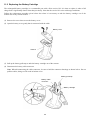
11.1
Charging and Discharging the Battery Cartridge ...................................................................................... 48
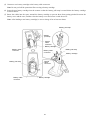
11.2
Replacing the Battery Cartridge................................................................................................................. 50
11.3
Recycling the Battery Cartridge................................................................................................................. 52
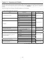
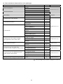
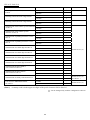
Chapter 12
Parameters and Defaults ............................................................................................................................ 53
(1) Bluetooth® communications parameters ........................................................................................ 53
(2) Data transmission format and bar code symbologies..................................................................... 54
(3) Trigger switch control and magic key control................................................................................ 59
(4) Beeper, indicator LED and vibrator ............................................................................................... 60
(5) Data verification mode ................................................................................................................... 61
(6) Notification of a scanning failure under software control ............................................................. 61
(7) Speed-/depth-priority scanning ...................................................................................................... 62
(8) Switching to sleep mode for power saving .................................................................................... 62
(9) For Bluetooth® adapter: Bluetooth® communications parameters ................................................. 63
(10) For Bluetooth® adapter: Interfaces ................................................................................................. 63
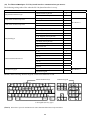
(11) For Bluetooth® adapter: USB keyboard interface communications parameters............................ 63
(12) For Bluetooth® adapter: USB-COM interface communications parameters ................................. 65
(13) For Bluetooth® adapter: RS-232C interface communications parameters..................................... 65
(14) For Bluetooth® adapter: PS/2 keyboard interface communications parameters ............................ 66
(15) For Bluetooth® adapter: Substitution of header/terminator for PS/2 and
USB keyboard interfaces ................................................................................................................ 68
Chapter 13
Bar-Coded Parameter Menu for Scanners................................................................................................. 69
13.1
Parameter Setting Procedure Using the Bar-Coded Parameter Menu ....................................................... 69
13.2
Bar-Coded Parameter Menu for Scanners ................................................................................................. 70
Starting/ending the setting procedure and reverting to defaults ......................................................... 71
Bluetooth® interface communications parameters .............................................................................. 72
Data transmission format and bar code symbologies ......................................................................... 74
Trigger switch control and magic key control .................................................................................... 84
Beeper, indicator LED and vibrator.................................................................................................... 85
Data verification mode ........................................................................................................................ 86
Notification of a scanning failure under software control.................................................................. 88
Reading with scanner mounted on charger......................................................................................... 89
Chapter 14
Bar-Coded Parameter Menu for Bluetooth® Adapters (BA10-RKU)....................................................... 90
14.1
Configuring the Bluetooth® Adapter from the Scanner............................................................................. 90
14.2
Bar-Coded Parameter Menu for Bluetooth® Adapters .............................................................................. 92
Starting and ending the setting procedure, and restoring to defaults ................................................. 92
Setting the interface............................................................................................................................. 92
Bluetooth® interface communications parameters .............................................................................. 93
USB keyboard interface communications parameters ........................................................................ 94
USB-COM interface communications parameters ............................................................................. 96
RS-232C interface communications parameters................................................................................. 97
PS/2 keyboard interface communications parameters ........................................................................ 99
Chapter 15
Troubleshooting.........................................................................................................................................101
Appendix 1
Specifications............................................................................................................................................103
Appendix 2
Bar Code Sample Label............................................................................................................................106
Appendix 3
Bluetooth® Glossary .................................................................................................................................108
Appendix 4
Pairing (Device authentication)................................................................................................................109
Appendix 5
Quick Setup for the Use of USB Keyboard Interface..............................................................................111
Appendix 6
Quick Setup for the Use of USB-COM Interface ....................................................................................114
Appendix 7
Quick Setup for the Use of RS-232C Interface........................................................................................119
Appendix 8
Quick Setup for the Use of PS/2 Keyboard Interface ..............................................................................123
Preface
This user's manual sets forth the procedures for handling, connecting, operating, and cleaning your bar code handy
scanner. Before you do anything else, study it carefully to make sure that you use the product both correctly and
effectively. Also keep it handy for ready reference.
i
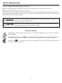
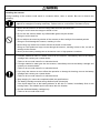
SAFETY PRECAUTIONS
Be sure to observe all these safety precautions.
Please READ through these instructions carefully. They will enable you to use the scanner correctly.
Always keep this manual nearby for speedy reference.
Strict observance of these warnings and cautions is a MUST for preventing accidents that could result in bodily injury
and substantial property damage. Make sure you fully understand all definitions of these terms and symbols given
below before you proceed to the text itself.
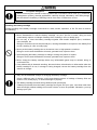
Alerts you to those conditions that could cause serious bodily injury or death if the
instructions are not followed correctly.
Alerts you to those conditions that could cause minor bodily injury or substantial property
damage if the instructions are not followed correctly.
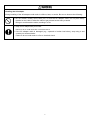
Meaning of Symbols
A triangle ( ) with a picture inside alerts you to a warning of danger. Here you see the warning for
electrical shock.
A diagonal line through a circle ( ) warns you of something you should not do; it may or may not have a
picture inside. Here you see a screwdriver inside the circle, meaning that you should not disassemble.
A black circle ( ) with a picture inside alerts you to something you MUST do. This example shows that
you MUST unplug the power cord.
ii
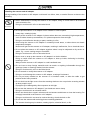
To System Designers:
• When introducing the scanner in those systems that could affect human lives (e.g., medicines
management system), develop applications carefully through redundancy and safety design
which avoids the feasibility of affecting human lives even if a data error occurs.
Handling the battery cartridge
Wrong handling of the battery cartridge could result in a heat, smoke, explosion, or fire. Be sure to observe
the following.
• Never disassemble or heat the battery cartridge, nor put it into fire or water; doing so could
cause battery-rupture or leakage of battery fluid, resulting in a fire or bodily injury.
• Do not carry or store the battery cartridge together with metallic ballpoint pens, necklaces,
coins, hairpins, etc.
Doing so could short-circuit the terminal pins, causing the batteries to rupture or the battery fluid
to leak, resulting in a fire or bodily injury.
• Never put the battery cartridge into a microwave oven or high-pressure container.
Doing so could cause the batteries to break, generate heat, rupture or burn.
• Avoid dropping the battery cartridge or letting it undergo any shock or impact.
Doing so could cause the batteries to break, generate heat, rupture or burn.
• Never charge the battery cartridge where any inflammable gases may be emitted; doing so
could cause fire.
• If any abnormality is detected--smoking, abnormal odors, discoloration or deformation when the
battery cartridge is in use, in storage or being charged, remove the battery cartridge from the
scanner or charger.
• Only use the dedicated charger for charging the battery cartridge.
Using a different type of charger could cause battery-rupture or leakage of battery fluid and
result in a fire, bodily injury, or serious damage to property.
• The battery cartridge contains strong alkaline liquid (electrolyte).
If battery liquid leaks from the battery cartridge and it gets into your eyes, rinse them with clean
water thoroughly without rubbing and consult a doctor as soon as possible. Otherwise, you may
damage your eyes.
iii
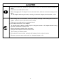
Handling the scanner
Wrong handling of the scanner could result in a scanner failure, heat, or smoke. Be sure to observe the
following.
• If using the hand strap or neck strap, exercise due care to avoid getting them caught in other
objects or entangled in rotating machinery. Failure to do so could result in accident or injury.
• Never use the scanner on the line voltage other than the specified level.
Doing so could cause the charger to break or burn.
• Do not use the scanner where any inflammable gases may be emitted.
Doing so could cause fire.
• Do not subject the scanning window of the scanner to direct sunlight for extended periods.
Doing so could damage the scanner, resulting in a fire.
• Never bring any metals into contact with the terminals in connectors.
Doing so could produce a large current through the scanner, resulting in heat or fire, as well as
damage to the scanner.
• Never put the battery cartridge into a microwave oven or high-pressure container.
• If smoke, abnormal odors or noises come from the scanner, immediately remove the battery
cartridge and contact your nearest dealer.
Failure to do so could cause fire or electrical shock.
• If foreign material or water gets into the scanner, immediately remove the battery cartridge and
contact your nearest dealer.
Failure to do so could cause fire or electrical shock.
• If you drop the scanner so as to affect the operation or damage its housing, remove the battery
cartridge and contact your nearest dealer.
Failure to do so could cause fire or electrical shock.
• Stop charging if it cannot be completed within the specified time.
• The battery cartridge contains strong alkaline liquid (electrolyte).
If the liquid leaked out of the battery adheres to the skin or clothes, immediately flush it with
running water. The alkaline liquid could cause the skin irritation.
• Use the dedicated battery cartridge only.
Failure to do so could result in fire.
iv
Handling the AC adapter
Wrong handling of the AC adapter could result in a failure, heat, or smoke. Be sure to observe the following.
• Do not scratch, modify, bend, twist, pull, or heat the AC adapter cable. Do not place heavy
material on the cable or allow the cable to get pressed under heavy material.
Doing so could break the cable, resulting in a fire.
• Keep the AC adapter away from water.
Failure to do so could cause fire or electrical shock.
• If the AC adapter cable is damaged (e.g., exposed or broken lead wires), stop using it and
contact your nearest dealer.
Failure to do so could result in a fire or electrical shock.
v
Handling the scanner and AC adapter
Wrong handling of the scanner or AC adapter could result in a failure, heat, or smoke. Be sure to observe the
following.
• Never disassemble or modify the scanner or AC adapter; doing so could result in an accident
such as break or fire.
Never
disassemble
Doing so could result in a fire or electrical shock.
• Do not put the scanner or AC adapter on an unstable or inclined plane.
It may drop, creating injuries.
• Never put the scanner or AC adapter in places where there are excessively high temperatures,
such as inside closed-up automobiles, or in places exposed to direct sunlight.
Doing so could affect the housing or parts, resulting in a fire.
• Avoid using the scanner or AC adapter in extremely humid areas, or where there are drastic
temperature changes.
Moisture will get into the scanner or AC adapter, resulting in malfunction, fire or electrical shock.
• Do not place the scanner or AC adapter anyplace where it may be subjected to oily smoke or
steam, e.g., near a cooking range or humidifier.
Doing so could result in a fire or electrical shock.
• Never cover or wrap up the scanner or AC adapter in a cloth or blanket.
Doing so could cause the scanner or AC adapter to heat up inside, deforming its housing,
resulting in a fire.
Always use the scanner or AC adapter in a well-ventilated area.
• Do not insert or drop foreign materials such as metals or anything inflammable through the
openings (vents or scanning window) into the scanner.
Doing so could result in a fire or electrical shock.
• Do not scratch or modify the scanner or AC adapter.
Doing so could damage the scanner or AC adapter, creating a fire hazard.
• Do not put heavy material on the scanner or its interface cable, or allow the cable to get
pressed under heavy material.
• Do not look into the light source from the scanning window or do not point the scanning window
at other people's eyes.
Eyesight may be damaged by direct exposure to this light.
• Do not use the scanner or AC adapter if your hands are wet or damp.
Doing so could result in an electrical shock.
• Never use chemicals or organic solvents such as benzene and thinner to clean the housing. Do
not apply insecticide to the scanner or AC adapter.
Doing so could result in a marred or cracked housing, electrical shock or fire.
• Do not use the scanner with anti-slip gloves containing plasticizer.
The scanner housing may be broken, creating injuries, electrical shock, or fire.
vi
• If you are not using the scanner for a long time, be sure to remove the battery cartridge for
safety.
Failure to do so could result in a fire.
• When unplugging the AC adapter from the electrical outlet, hold the connector housing not the
cable.
The AC adapter cable may be broken, resulting in a burnt AC adapter, electrical shock, or fire.
• When taking care of the scanner, remove the battery cartridge. When taking care of the AC
adapter, unplug it from the electrical outlet for safety.
Failure to do so could result in an electrical shock.
• Do not drop the scanner or AC adapter.
The housing may be broken, creating injuries. Using the scanner or AC adapter whose housing
is broken could result in smoke or fire.
Remove the battery cartridge from the scanner.
Unplug the AC adapter from the electrical outlet.
Then contact your nearest dealer.
• During electrical storm activity, unplug the AC adapter from the electrical outlet.
Exposure to power surges could result in a damaged charger or fire.
vii
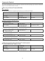
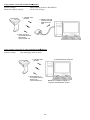
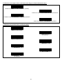
Components Required
The scanner GT10B-SB/LB requires the following components that differ depending upon whether the Bluetooth®
adapter is used and which interface is selected.
®
When using the Bluetooth adapter (BA10-RKU)
Basic components
The table below lists the basic components required for the use of the Bluetooth® adapter.
(1) Scanner
GT10B-SB/LB
(2) Bluetooth® adapter
BA10-RKU
(3) Charger
CH-GT10N
(4) AC adapter
AD2-2005/3000 (USA)
AD2-3005/3000 (EU)
For charger
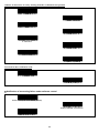
Components required for individual interfaces
• For RS-232C interface
(5) RS-232C interface cable
CBBA-RS2000/9
(6) AC adapter
AD2-2005/3000 (USA)
AD2-3005/3000 (EU)
For Bluetooth® adapter
• For RS-232C interface and Bluetooth® adapter mounted in the charger
(5) RS-232C interface cable,
Charger built-in type
CBBA-RS2000/9-1
• For PS/2 keyboard interface
(5) PS/2 keyboard interface cable
CBBA-KYS2000/6
• For USB keyboard or USB-COM interface
(5) USB interface cable
CBBA-US2000/4
®
When directly communicating with Bluetooth -enabled equipment
®
(no BA10-RKU Bluetooth adapter is used)
(1) Scanner
GT10B-SB/LB
(2) Charger
CH-GT10N
(3) AC adapter
AD2-2005/3000 (USA)
AD2-3005/3000 (EU)
viii
For charger
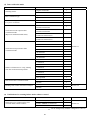
Bluetooth® Wireless Communication Link
The scanner GT10B-SB/LB uses Bluetooth® wireless networking technology.
Item
Specifications
Standard
Bluetooth® Specification Ver. 1.1
Radio output
Class 2 (maximum 2.5 mW)
Profile(s) supported
Serial port profile
Communications range (reference value*1)
Max. 10 m, with no obstructions
*1 This value is for wireless networking between the scanner and the BA10-RKU Bluetooth® adapter. The communications
range varies with the equipment used and the operating environment.
Wireless networking requires a stable radio environment. Not all operating environments provide this. In particular,
note that
• Using the scanner in close proximity to other wireless LAN equipment operating in the same frequency band (2.4
GHz) risks radio interference that can reduce throughput or even entirely block wireless networking.
• Microwave ovens, industrial heating equipment, high-frequency medical equipment, and other equipment using the
2.4 GHz band can sometimes block wireless networking.
• Electromagnetic noise from computers, refrigerators, and other home appliances can sometimes block wireless
networking.
• The following environments can sometimes block wireless networking.
- Metal objects or particles in the vicinity
- Metal walls around the area
- Excessive vibration
• The communications range of 10 m given above is merely a reference value assuming a clear line of sight. Reliable
wireless networking is by no means guaranteed at 10 m for all combinations of equipment used and operating
environments. Some combinations might even work for greater distances, but be sure to confirm that the scanner
link operates properly before introducing the link operation.
NOTE: To System Designers:
• Before developing applications, make sure that the intended environment is free of the interference factors
above and thus actually capable of supporting link operation.
• When introducing the scanner into an environment where equipment using radio waves in the 2.4 GHz
band operates or when introducing such equipment after the introduction of the scanner, be sure to confirm
that the scanner radio link operates properly with all equipment being in operation beforehand.
• If the environment of the radio communications system is changed after the introduction (e.g., newly
installed household appliances and movement/addition of shelves or objects), then confirm that the radio
link operates properly again before the actual use.
ix
Care and Maintenance
Dust and other foreign matter on the clear plate of the reading window can impede bar code input, so regularly check
for it and remove it as the usage environment warrants.
• To clean the plate, first blow the dust away with an airbrush. Then gently wipe the plate with a cotton swab or the
similar soft one.
• If sand or hard particles have accumulated, never rub the plate; doing so will scratch or damage it. Blow the
particles away with an airbrush or a soft brush.
x
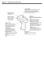
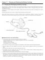
Chapter 1
Part Names and Functions
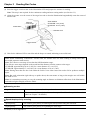
Indicator LED
This turns blue after a successful read and red
if there is an error. It also indicates the
Bluetooth® interface status and, when the
scanner is in its charger, the charging status.
(Refer to Chapter 9 for details.)
Reading window
Point this at the bar
code to read.
Magic key
Built-in antenna
Holding down this key for approx. 2
seconds breaks Bluetooth® wireless
links.
This key also functions as an
auxiliary key for reads, data
transfers, and the like. These
auxiliary functions include:
- Illumination LED switching function
- Data retransfer function
- Specific character transfer function
- Ready/standby switching function
- Auto sensing mode switching
function
- Continuous reading mode
switching function
(The factory configuration assigns
none of these functions to this key.)
Refer to Chapter 6 for details.
®
Bluetooth antenna.
Do not modify this
antenna section or
cover it by hand.
Trigger switch
Press this to read a bar code or
initiate a Bluetooth® wireless link.
The following trigger switch
operating modes are available:
• Auto-off mode 1
• Auto-off mode 2
• Momentary switching mode 1
• Momentary switching mode 2
• Continuous reading mode
(The factory default is momentary
switching mode 1.)
In addition, the auto sensing mode is
also available for automatic trigger
operation.
Refer to Chapters 2 and 5 for
details.
Battery cover
Remove this to replace the battery
cartridge.
(Refer to Chapter 11 for details.)
1
Chapter 2
Bluetooth® Interface
For terms relating to Bluetooth® wireless communication in this manual, refer to Appendix 3 "Bluetooth® Glossary."
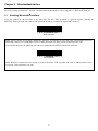
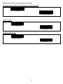
2.1
Enabling Bluetooth® Interface
Using the scanner for the first time or any other time that the "End operation" is selected requires scanning the
following "Start operation" bar code to start operation. Scanning it enables the Bluetooth® interface.
Start operation
Note: Always disable this scanner's Bluetooth® interface in hospitals, aircraft, and other environments where the
Bluetooth® radio waves (2400 MHz to 2483.5 MHz, maximum 2.5 mW) present a potential safety risk.
This scanner interprets the following bar code as a command to disable the Bluetooth® interface.
End operation
Note: When the scanner leaves the factory or it has scanned the "End operation" bar code, it cannot read bar codes
except the "Start operation" bar code.
2
2.2
Establishing Bluetooth® Wireless Link
After enabling the Bluetooth® interface, establish a Bluetooth® wireless link between the scanner and the BA10-RKU
Bluetooth® adapter (or some other Bluetooth® equipment) using the following procedures. The scanner can act as both
a master and slave (default).
A scanner configured and connected as a master remembers previous target devices, so, even if the link is broken,
pressing the scanner trigger switch is all that it takes to reconnect.
Scanner as Master
®
Using the Bluetooth adapter
(1) Use the scanner to read the bar code on the back of the Bluetooth® adapter.
The scanner configures itself as a master and establishes a Bluetooth® wireless link with the Bluetooth® adapter.
Even if the scanner has been configured as a slave, reading this bar code initiates connection as a master.
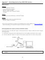
(2) Wait for the scanner to beep twice and the indicator LED to turn green (for 0.5 second).
Using some other Bluetooth® device
To configure the scanner as a master and some other Bluetooth® equipment as a slave, follow the sample procedures
given below and specify the slave's Bluetooth® address to the scanner. The connection ratio of the scanner and slave
device should be 1:1.
(1) Confirm the device's Bluetooth® address.
For the instructions on how to confirm, see the user's manual.
(2) Create a "Bluetooth® address" bar code for the Bluetooth® address thus obtained.
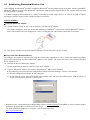
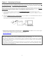
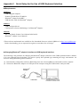
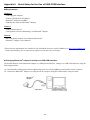
z The following is the procedure for configuration software (ScannerSetting)* versions 2.4.0 and later.
1) Run the configuration software on your computer.
2) On the Options screen, select GT10B SB as the product name and press the Offline button. (Shown below is a
screen in configuration software version 2.5.0.)
* Registered users can download the configuration software (ScannerSetting) from QBdirect, their customer support
section on the Denso Wave website at no extra charge.
For further details on QBdirect or to register, visit the following URL.
http://www.qbdirect.net
3
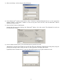
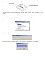
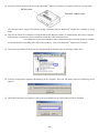
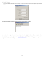
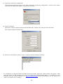
3) Select an arbitrary version and press the OK button.
4) On the Bluetooth® window shown below, select "Connect to optional Bluetooth device" as the Connection
method, "Master" as the Mode, "Address" as the Access point. In the text box, enter the Bluetooth® address
obtained in step (1) above.
5) Press the Print Connect Label button.
Pressing the Preview button displays the "Bluetooth® address" bar code created. The displayed bar code can
be read with the scanner.
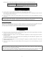
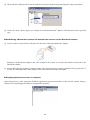
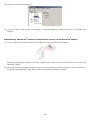
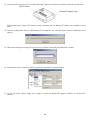
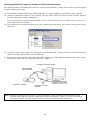
6) On the window shown below, press the Print button to print the bar code.
Alternatively, press the Copy button to copy the bar code to the Windows Clipboard as bit map data (.bmp) for
pasting into an image editor, word processor, or other application accepting that format.
(Optional) In the Comment text box, enter any desired descriptive text to print with the bar code.
4
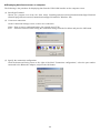
z When
using a commercially available bar code generator, generate it in the following format.
Bar code type
Code 128, Code set A
Value
ADDR followed by Bluetooth® address (in hexadecimal)
(Example) Bluetooth® address 000AF1234567
ADDR000AF1234567
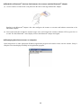
(3) Use the scanner to read the "Bluetooth® address" bar code created in step (2) above.
The scanner as a master initiates connection to the specified Bluetooth® device, switching the scanner from the
slave configuration first, if necessary.
(4) Wait for the scanner to beep twice and the indicator LED to turn green (for 0.5 second), indicating a successful
connection.
Note: The scanner supports Bluetooth® pairing (authentication using pass keys) when connecting to slave devices.
For further details, first see Appendix 4 and then refer to the user's manual for the target device.
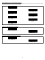
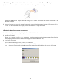
Scanner as Slave (default)
The scanner is a slave by default. This slave can establish a Bluetooth® wireless link with the BA10-RKU Bluetooth®
adapter (or some other Bluetooth® equipment) as a master without special communication procedures.
(1) If the scanner is currently a master, read the following bar code to switch it to slave operation.
Configure as slave
(2) Wait for the scanner to beep three times, press the scanner's trigger switch, and wait approximately two minutes
(default) for the master device to connect to this slave.
(3) Configure the Bluetooth® adapter (or some other Bluetooth® equipment) as a master and specify the scanner's
Bluetooth® address.
For the Bluetooth® adapter, use the configuration software (BASetting). (For other Bluetooth® equipment, use the
procedures set forth in the user's manual.)
(4) Wait for the Bluetooth® adapter (or some other Bluetooth® equipment) to establish a Bluetooth® wireless link
with the scanner as a slave.
(5) Wait for the scanner to beep twice and the indicator LED to turn green (for 0.5 second), indicating a successful
connection.
Note: If a search by a master device finds no scanners within effective range, increase the scanner connection
timeout interval for slave operation and try again.
Note: The scanner also supports Bluetooth® pairing (authentication using pass keys) when connecting to master
devices. For further details, first see Appendix 4 and then refer to the user's manual for the target device.
5
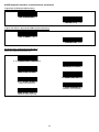
2.3
Breaking Bluetooth® Wireless Links
Holding down the magic key in the regular read mode breaks the scanner's Bluetooth® wireless link.
Scanning the following bar code forcibly breaks the scanner's Bluetooth® wireless link.
Break Bluetooth® wireless link
Note: Breaking the Bluetooth® wireless link does not disable the Bluetooth® interface. To disable it, scan the
"Stop operation" bar code.
Note: In the data verification mode, the magic key is used to register master data, not used to break the Bluetooth®
wireless link. To break the link, use the scanner to read the "Break Bluetooth® wireless link" bar code. Note that
when the scanner, as a master, is searching for a connection target or it is, as a slave, waiting for a master to
connect, the magic key can break the Bluetooth® wireless link.
2.4
Reestablishing Bluetooth® Wireless Links
When the scanner's Bluetooth® wireless link has been broken by any of the following events, pressing the trigger
switch reestablishes the Bluetooth® wireless link. The scanner as a slave waits for a connection request from the
master; the scanner as a master reconnects to a target slave.
-
Scanning the "Start operation" bar code
Scanning the "Break Bluetooth® wireless link" bar code
Pressing the magic key to break the Bluetooth® wireless link
Customizing the scanner with the configuration software (ScannerSetting)
"Reconnect request" dialog being displayed by the configuration software (ScannerSetting)
Replacing the battery cartridge
Failure to automatically reconnect within the specified time
If the Bluetooth® wireless link breaks for some reason other than the above--degraded radio wave conditions, or loss
of power to the Bluetooth® adapter, commercially available Bluetooth® device, or other target device, for example--the
scanner automatically tries to reconnect for approximately 40 seconds for master operation or for the user-specified
connection timeout interval for slave operation.
6
2.5
Indication of Bluetooth® Wireless Link Status
The scanner's indicator LED and beeper together indicate the status of the scanner's Bluetooth® wireless link.
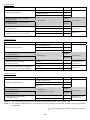
When the trigger switch is held down:
Indicator LED
Red, blinking
Beeper
Silent
Red, blinking twice repeatedly
Scanner Status
Reading is not possible when there is no Bluetooth® wireless link.
The scanner has scanned the "End operation" bar code.
When the trigger switch is pressed and released:
Indicator LED
Blue, blinking rapidly
Beeper
Silent
Blue, blinking slowly
Scanner Status
The scanner, as a master, is searching for a connection target.
The scanner, as a slave, is waiting for a master to connect.
When the Bluetooth® wireless link is established or broken:
Indicator LED
Beeper
Scanner Status
®
Green for 0.5 second
Two short beeps
The Bluetooth wireless link is ready for use.
Red for 0.5 second
Long beep
The Bluetooth® wireless link no longer exists.
7
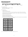
Chapter 3
Reading Bar Codes
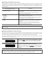
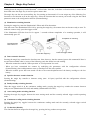
(1) Press the trigger switch to turn on the illumination LED and prepare the scanner for reading.
Note: This step is not required for the continuous reading and auto sensing modes (see Section 5.3).
(2) Align the scanner over the center of the target bar code so that the illumination longitudinally scans the center of
the bar code.
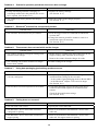
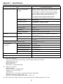
Scan distance
GT10B-SB: 7 cm (2.76")
GT10B-LB: 18 cm (7.09")
Effective
scan range
Illumination
Indicator LED
Trigger switch
(3) Wait for the indicator LED to turn blue and the beeper to sound, indicating a successful read.
Note: While establishing a Bluetooth® wireless link, the scanner does not allow reading in things other than
bar-coded parameter menu entries.
Note: The effective scan range is less than the full illumination range.
The effective scan range depends on the model and the distance from the scanner to the target.
GT10B-SB: approximately 10 cm (3.94") for a scan distance of 7 cm (2.76")
GT10B-LB: approximately 17 cm (6.69") for a scan distance of 18 cm (7.09")
Note: Having more than one bar code within the field of view either causes the read to fail or produces multiple
input.
Note: Bar code orientation (right side up or upside down) does not matter as long as the margins are well within
the field of view.
Note: It is sometimes necessary to vary the scanning angle or distance to eliminate reflections of the illumination
and ambient light off highly reflective labels.
Scanning modes
Regular read mode
Successful completion of read-in produces data transfer.
Data verification mode
The scanner transfers only data that matches a predefined list of acceptable bar codes.
(Refer to Chapter 7 for details.)
Speed-/depth-priority scanning
Speed-priority
The scanner gives priority to reducing the time spent decoding bar code data.
Depth-priority
The scanner gives priority to expanding the scan range.
For details, refer to Appendix 1.
8
Reading RSS-14 Stacked and RSS-14 Stacked Omnidirectional symbols
The scanner reads RSS-14 Stacked and RSS-14 Stacked Omnidirectional symbols in two steps. In the 1st step, it scans
either one of the 1st and 2nd rows of the target symbol and accumulates the data in itself. In the 2nd step, it scans the
remaining row, edits the 1st and 2nd row data read, and then sends the data to the host.
To inform the user that the 1st or 2nd row data has accumulated in the scanner, the scanner emits a one-shot beep by
default. Upon completion of a successful read of the remaining row, the scanner emits a short beep just as upon
completion of a read of any other type of bar code.
To discard the accumulated data halfway through a sequence of scanning, turn off the illumination LED. In the
continuous reading mode or auto sensing mode, however, move the illumination away from the target symbol.
9
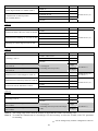
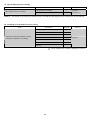
Switching to sleep mode for power saving
After completion of scanning, the scanner switches from standby to sleep mode to save power. The scanner in sleep
mode takes more time to start and complete a sequence of scanning operation than the one on standby. Select the
transition period from standby to sleep mode to meet your scanning intervals, using the configuration software
(ScannerSetting).
Transition period from standby to sleep mode
after completion of scanning:
Immediately (default)
Description
After completion of scanning, the scanner immediately switches
to sleep mode.
This setting is useful for operations with longer scanning
intervals, e.g., 5 minutes or more.
5 seconds
15 seconds
30 seconds
1 minute
5 minutes
After completion of scanning, the scanner waits for the specified
period and then switches to sleep mode.
Disable
The scanner does not switch to sleep mode after completion of
scanning.
This setting is useful for intermittent scanning. Select a transition
period suitable for your scanning intervals.
This setting is useful for operations with shorter scanning
intervals, 5 seconds or less or when the scanning speed should
have priority over the power saving.
Note: Selecting a longer transition period or disabling switching to sleep mode shortens the operation time of the
battery cartridge.
®
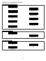
Scanning with Bluetooth wireless link broken
The scanner can read bar codes even with the Bluetooth® wireless link being broken. Use this scanning way when
scanning bar codes is required but data transfer is not, for instance, when the scanner itself checks the verification
result (with the scan lock enabled as described in Section 7.1) without transferring it to the host computer.
Scanning with Bluetooth® wireless link broken and that with Bluetooth® wireless link established can be switched
only with the bar-coded parameter menu.
Scan w/ Bluetooth® link broken
Allows the scanner to scan bar codes with the Bluetooth® wireless
link being broken. This bar code also disables the Bluetooth®
interface, making data transfer with the host computer impossible.
Cancel "Scan w/ Bluetooth® link broken"
Cancels the "Scan w/ Bluetooth® link broken" setting.
This bar code allows the scanner to scan bar codes with the
Bluetooth® wireless link being established. It also enables the
Bluetooth® interface, making data transfer with the host computer
possible.
Note: The "Scan w/ Bluetooth® link broken" parameter retains its setting even the scanner reads the "End
operation" and "Start operation" bar codes in this order with the "Scan w/ Bluetooth® link broken" being selected.
To cancel the setting, you need to scan the "Cancel "Scan w/ Bluetooth® link broken"" bar code.
10
Chapter 4
Customizing the Scanner
You can customize the scanner by modifying communications, bar code type, and other scanner parameters with the
bar-coded parameter menu or the configuration software ScannerSetting*. These parameters retain their settings even
when the power is off.
TIP: The scanner can hold not only its own parameter settings but also Bluetooth® adapter parameter settings in its
memory and customize the Bluetooth® adapter via the Bluetooth® wireless link. There are two types of bar-coded
parameter menus available for scanners (Section 13.2) and Bluetooth® adapters (Section 14.2).
(1) Scanning parameter setting bar codes from the bar-coded parameter menu by pressing the trigger switch.
(The bar-coded parameter menus for scanners and Bluetooth® adapters are given in Chapters 13 and 14,
respectively.)
(2) Using the configuration software (ScannerSetting)* in your computer. It is recommended that the scanner be
configured as a master.
(This software also offers batch-process bar code printouts for read by scanners in the field.)
* Registered users can download the configuration software (ScannerSetting) from QBdirect, their customer support
section on the Denso Wave website at no extra charge.
For further details on QBdirect or to register, visit the following URL.
http://www.qbdirect.net
Note: Customizing the scanner with the configuration software or batch-process bar code symbols breaks the
Bluetooth® wireless link, so it is necessary to establish the link again after customizing.
Note: When the "End operation" is selected with the scanner, no parameter setting is possible. Prior to starting
parameter setting, therefore, be sure to scan the "Start operation" bar code. See Chapter 2 for the "Start operation"
and "End operation" bar codes.
Note: When even the scanner is being charged or discharged, you can customize it with the configuration software
except when the "End operation" is selected. Note that customizing the scanner during discharge cancels
discharging and starts charging instead.
11
Chapter 5
Scanning Control
Two types of scanning controls are available—Trigger switch control and Software control.
Trigger switch control: Pressing the trigger switch readies the scanner for scanning.
Software control: Instead of pressing the trigger switch, you send control commands from the host computer via the
USB-COM interface to ready the scanner for scanning or put the scanner on standby.
5.1
Trigger Switch Control
Pressing the trigger switch turns on the illumination LED and readies the scanner for scanning. The scanner supports
the following five trigger switch operating modes. Select the one that best meets your needs using the bar-coded
parameter menu or the configuration software (ScannerSetting).
(1) Auto-off mode 1
Holding down the trigger switch lights the illumination LED for the specified period (selectable from 1 to 5 seconds in
one second increments with the configuration software), during which the scanner is ready to scan.
When a bar code is read successfully or the specified period has elapsed, the illumination LED goes off and the
scanner switches to standby.
(2) Auto-off mode 2
If you press the trigger switch, the illumination LED lights for approx. 5 seconds during which the scanner is ready to
scan, regardless of whether a bar code is read successfully or the trigger switch is released.
After a bar code is read successfully, the ready-to-scan state further continues for approx. 5 seconds.
If the scanner is left without scanning operation for approx. 5 seconds, it turns off the illumination LED and switches
to standby.
(3) Momentary switching mode 1 (Factory default)
Only while you hold down the trigger switch, the illumination LED lights and the scanner is ready to scan.
When you release the trigger switch or a bar code is read successfully, the illumination LED goes off and the scanner
switches to standby.
(4) Momentary switching mode 2
Only while you hold down the trigger switch, the illumination LED lights and the scanner is ready to scan, regardless
of whether a bar code is read successfully.
When you release the trigger switch, the illumination LED goes off and the scanner switches to standby.
(5) Continuous reading mode
When you turn the scanner on, the scanner lights the illumination LED and becomes ready to scan. The scanner
ignores all trigger switch input.
Note: The scanner automatically enters the momentary switching mode 1 regardless of the current trigger switch
operating mode when:
- the scanner is being customized with the bar-coded parameter menu
- the "End operation" is selected
- the Bluetooth® wireless link is broken
Note: The trigger switch is disabled as long as the scan lock (see Section 7.1.3) is in effect in the data verification
mode.
12
5.2
Software Control
You can control the scanner by sending scanning control commands from the host computer, instead of pressing the
trigger switch.
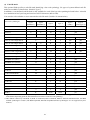
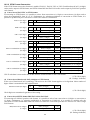
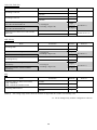
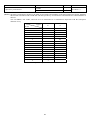
Scanning control commands include R, READON, LON, RC, Z, READOFF and LOFF and they are restricted by the
trigger switch operating mode, as listed below. In momentary switching mode 1, for example, the RC command is
invalid. In auto-off mode 2 and momentary switching mode 2, all of these commands are invalid.
(√: Command valid)
Trigger switch operating modes
Commands
Description
R,
READON,
LON
Ready-to-scan commands
Upon receipt of one of these commands,
the scanner turns on the illumination
LED and becomes ready to scan.
RC
Z,
READOFF,
LOFF
Momentary Momentary
Continuous
switching
switching
reading mode
mode 1
mode 2
Auto-off
mode 1
Auto-off
mode 2
√
--
√
--
√
--
--
--
--
√
--
--
√
--
√
Standby commands
Upon receipt of one of these commands,
the scanner turns off the illumination
LED and switches to standby.
Each of these commands should be enclosed with a header and terminator for transmission according to the
communications conditions of the scanner.
Note: When the scanner is ready to scan with an R, READON or LON command, pressing the trigger switch cancels
the command control, producing the operation specified for the trigger switch.
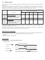
Notification of a scanning failure
If the scanner fails to read a bar code and switches to standby in auto-off mode 1 or momentary switching mode 1, it
can send the following two types of notification data (cancel or error) to the host computer.
- CAN (18h)
- "ERROR" (with header and terminator)
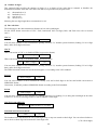
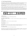
Control scheme
(1) Auto-off mode 1 or momentary switching mode 1
Successful read
Ready-to-scan command
Command input (RxD)
Bar code
Illumination LED
Bar code data
Data output (TxD)
13
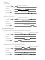
Failure read
• Auto-off mode 1
Ready-to-scan command
Command input (RxD)
Bar code
1 to 5 sec.
Illumination LED
Failure notification
Data output (TxD)
• Momentary switching mode 1
Ready-to-scan command
Command input (RxD)
Standby command
Bar code
Illumination LED
Failure notification
Data output (TxD)
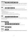
(2) Continuous reading mode
Switching to the ready-to-scan state with an R, READON or LON command
Ready-to-scan command
Standby command
Command input (RxD)
Bar code
Illumination LED
Bar code data
Data output (TxD)
Switching to the ready-to-scan state with an RC command
Ready-to-scan command
Standby command
Command input (RxD)
Bar code
Illumination LED
Bar code data
Data output (TxD)
14
5.3
Auto Sensing Mode—Automatic Detection of Labels
In the auto sensing mode, bringing a code label within the scan range of the reading window turns on the illumination
LED and starts the scanner reading the bar code. No trigger switch operation is required. Use this mode when the
scanner is stationary to a stand and a bar code label is moved.
The illumination LED comes on when you bring a bar code label within the designated range or move a bar code label
within the same range. The LED goes off when a bar code label is moved away from the range or stays within the
range without move for approx. 5 seconds.
The scanner offers a choice of three sensitivity levels for responding to bar codes--High, Medium, and Low. Switch to
a higher sensitivity level if the illumination LED will not come on when a bar code is brought into the range, for
example.
Note: Even if you do not bring a bar code label within the scan range, the illumination LED may come on when
the ambient level of light changes or any shadows move within the scan range.
Note: Even if you do not bring a bar code label within the scan range, the illumination LED may come on when
the ambient level of light changes or any shadows move within the scan range.
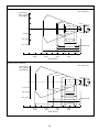
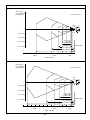
Note: Given below is a guide for scanning EAN-13 symbols in auto sensing mode under these conditions: At the
center of the effective scan range and at the ambient illuminance of 500 lux or higher.
GT10B-SB: Scan distance of approx. 21 cm (8.27")
GT10B-LB: Scan distance of approx. 40 cm (15.75")
Note: It is sometimes necessary to vary the scanning angle or distance to eliminate reflections of the illumination
and ambient light off highly reflective labels.
15
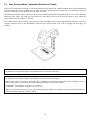
5.4
Reading with Scanner Mounted on Charger
A setting enables read operation with the scanner mounted on the charger, drawing its power from the charging pins,
so reading can continue regardless of the battery cartridge's charge level.
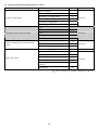
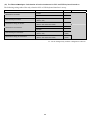
The following table shows how the trigger switch operating mode affects charging while this function is in use.
Momentary switch mode 1, for example, allows charging during standby intervals between reads. Configuring for
continuous reading or auto sensing mode, however, disables recharging.
Trigger switch operating mode
Scanner state
Auto-off
mode 2
--
--
--
--
--
--
Illumination LED OFF
after completion of bar
code reading
√
√
√
√
--
--
On standby
after receipt of Z,
READOFF, or LOFF
command
√
√
√
√
√
--
Charging during reads
- Reading in bar codes
- Illumination LED ON
Charging
between reads
Momentary Momentary Continuous
Auto sensing
switching
switching
reading
mode
mode 1
mode 2
mode
Auto-off
mode 1
Note: Scanners with the following model numbers have this enable setting, but do not support reading.
٠ 454800-8620
٠ 454800-8630
16
Chapter 6
Magic Key Control
Holding down the magic key breaks Bluetooth® wireless links. Note that, in the data verification mode, it cannot break
those links since the magic key is used to register master data.
The magic key can also act as an auxiliary key for scanning or data transfer. You can assign any of the following five
functions or no function at all to the magic key. Select the function that best meets your needs using the bar-coded
parameter menu or the configuration software (ScannerSetting).
(1) Illumination switching function
Pressing the magic key turns the illumination LED on and off in alternation.
Note that even if the illumination LED is lit by pressing the magic key, the scanner does not become ready to scan. To
make the scanner ready, press the trigger switch.
If the illumination LED has been lit for approx. 3 seconds without completion of a scanning operation, it will
automatically goes off.
Completion of scanning
The illumination
LED comes on.
Press the magic key.
Press the trigger switch.
(2) Data retransfer function
Pressing the magic key retransfers the last data sent. Note, however, that the scanner ignores this command if there is
no such data available--that is, in any of the following cases that follow bar code reading.
- When the scanner has read the "Start operation" or "End operation" bar code
- When you have customized the scanner by modifying the parameters with the configuration software
(ScannerSetting), bar-coded parameter menu, or batch-process bar code symbols
- When the scanner power has been turned off due to the removal/replacement of the battery cartridge or the low
battery.
(3) Specific character transfer function
Pressing the magic key transfers a character string (max. 10 bytes) specified with the configuration software
(ScannerSetting).
(4) Ready/standby switching function
When the trigger switch is in the continuous reading mode, pressing the magic key switches the scanner between
ready-to-scan (illumination LED ON) and standby (illumination LED OFF).
(5) Auto sensing mode switching function
Pressing the magic key toggles between the auto sensing mode and the currently selected trigger switch operating
mode.
(6) Continuous reading mode switching function
Pressing the magic key toggles between the continuous reading mode and the currently selected trigger switch
operating mode.
(7) No function (Disable)
If no function has been assigned to the magic key, pressing the key produces no operation.
17
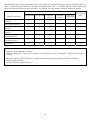
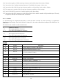
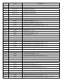
The following table lists the relationship between the magic key functions and trigger switch operating modes. (It
applies to both the regular read mode and data verification mode.) The "--" indicates that the scanner ignores the
magic key functions assigned. In auto-off mode 1, for example, the ready/standby switching function is ignored.
Trigger switch operating modes
Magic key functions
Auto-off mode Auto-off mode
1
2
Momentary
switching
mode 1
Momentary
switching
mode 2
Continuous
reading mode
Auto sensing
mode
Illumination switching
function
√
√
√
√
--
--
Data retransfer function
√
√
√
√
√
√
Specific character transfer
function
√
√
√
√
√
√
Ready/standby switching
function
--
--
--
--
√
--
Auto sensing mode
switching function
√
√
√
√
√
--
Continuous reading mode
switching function
√
√
√
√
--
√
No function
√
√
√
√
√
√
Note: In any of the following cases, the magic key is disabled regardless of the current function being assigned.
- When the "End operation" is selected
- When the Bluetooth® wireless link is broken, except when the "Scan w/ Bluetooth® wireless link broken" is
selected
Note: Selecting the "Scan w/ Bluetooth® wireless link broken" disables the following magic key functions.
- Data retransfer function
- Specific character transfer function
18
Chapter 7
7.1
Scanning Functions
Data Verification Mode
The data verification mode verifies the bar code data read against the master data stored in the scanner and reports the
match status with data output.
Data verification read is available in two types--"n-point verification" and "2-point verification."
Selecting the n-point verification requires registering master data only one time for 1:n verification. The scanner
verifies all bar code data read after registration against the master data.
The 2-point verification refers to 1:1 verification. Selecting it requires registering master data each time preceding bar
code scanning. After registration of master data, the scanner reads a bar code, verifies the bar code data read against
the master data and then becomes ready to register new master data. This way, the 2-point verification read alternately
repeats master data registration and bar code scanning.
The master data registration procedure is different in n-point and 2-point verification reads. (See Section 7.1.1.)
The verification parameters can be specified using the bar-coded parameter menu or configuration software
(ScannerSetting). After specifying them, scan a master bar code, and the scanner becomes capable of data verification
read.
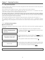
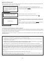
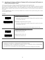
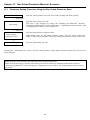
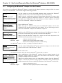
7.1.1 Verification setup procedure
n-point verification read
After one-time registration of master data, the scanner verifies all bar code data read after registration against the
master data.
- Switch to the data verification mode.
- Specify the verification parameters
(verification conditions and result
output ways).
Use the bar-coded parameter menu or the configuration software.
The indicator LED flashes in red, indicating that no master bar code is
registered in the scanner.
↓
Scan a master bar code to register.
(Registration of master data)
Hold down the magic key to turn the indicator LED in green. Keep the
magic key held down and press the trigger switch to scan a master bar
code.
After registration of master data, the indicator LED goes off.
↓
Scan bar codes.
Use the scanner to scan a target bar code. The scanner verifies the bar
code read against the master data registered and then outputs the result.
After a successful read, the indicator LED lights in blue.
Note: For what clears the registered master data, see the next page.
19
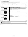
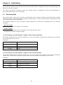
2-point verification read
After registration of master data, the scanner reads a bar code, verifies the bar code data read against the master data
and then becomes ready to register new master data.
- Switch to the data verification mode.
- Specify the verification parameters
(verification conditions, result output
ways, and verification retry after
mismatch*).
Use the bar-coded parameter menu or configuration software.
The indicator LED lights in green, indicating that the scanner is ready
to register master data.
↓
Scan a master bar code to register.
(Registration of master data)
Press the trigger switch to scan a master bar code.
After registration of master data, the indicator LED goes off.
↓
Scan bar codes.
Use the scanner to scan a target bar code. The scanner verifies the bar
code read against the master data registered and then outputs the
result.
After a successful read, the indicator LED lights in green, indicating
that the scanner is ready to register new master data.
*Verification retry after mismatch in 2-point verification
The 2-point verification read provides the "Verification retry after mismatch" option that retries verification against
the same master data. Enabling this option readies the scanner not for registering new master data but for reading a bar
code again if the verification result is a mismatch.
Disabling this option readies the scanner for registering new master data after bar code reading, no matter what the
verification result is.
Note: Any of the following events clears the master data stored in the scanner.
- Scanning the "Start operation" or "End operation" bar code with the scanner.
- Customizing the scanner by modifying the parameters with the configuration software (ScannerSetting) or
batch-process bar code symbols.
- Modifying the "verification start position in data verification mode" or "number of characters to verify, starting
from the verification start position" setting with the bar-coded parameter menu.
- The scanner power is turned off due to the removal/replacement of the battery cartridge or the low battery.
Note: In the data verification mode, the magic key is used to register master data, not used to break the Bluetooth®
wireless link. To break the link, scan the "Break Bluetooth® wireless link" bar code. Note that when the scanner, as
a master, is searching for a connection target or it is, as a slave, waiting for a master to connect, the magic key can
break the Bluetooth® wireless link. See Section 2.3 for details about the "Break Bluetooth® wireless link" bar code.
Note: To break the Bluetooth® wireless link with no master data registered, follow the procedure set forth in
Section 7.1.5.
Note: Registering master data is not possible without a Bluetooth® wireless link.
Note: Enabling "Reading with scanner mounted on charger" allows registering of master data on the charger, but
the indicator LED gives priority to displaying the charge state.
20
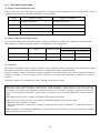
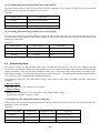
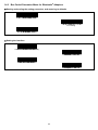
7.1.2 Verification conditions
You can specify a verification starting position and the number of characters to check.
• Starting position:
The choices are 1st through 7th characters.
• Number of characters: The choices are 1 through 7 and everything following the starting position (up to a
maximum of 32 characters).
For example, you can specify all characters or particular characters of bar code data to check as shown below.
Master data
Verification conditions: All characters to check
To check all characters as underlined at left, for example, set the following:
12345601
Bar code data readable
- Starting position:
1st character
- Number of characters: All characters
Max. 32 bytes of bar code data can be verified.
12345601
Master data
Verification conditions: Particular characters to check
To check particular characters as underlined at left, for example, set the
following:
12345601
Bar code data readable
- Starting position:
3rd character
- Number of characters: 2 characters
01347803
Note: If the bar code type (symbology) of data read is different from that of the master data, the verification results
in a mismatch even if those data matches.
21
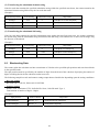
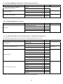
7.1.3 Verification result output
(1) Report of match/mismatch status
You can select any of the following report types by using the bar-coded parameter menu or configuration software
(ScannerSetting). Selecting "Disable transmission" reports nothing.
Setting
If there is a match:
If there is a mismatch:
1
Disable transmission.
Disable transmission.
2
Enable bar code data transmission.
Disable transmission.
3
Enable bar code data transmission.
Enable NG transmission.
4
Enable OK transmission.
Enable NG transmission.
(2) Beeper, indicator LED and vibrator
You can check whether the verification result is a match or mismatch, with the beeper, indicator LED and vibrator.
When the beeper, indicator LED and vibrator are enabled, they act as listed below.
Beeper
Indicator LED
Vibrator
"OK" vibrations "NG" vibrations
If there is a match:
Emits a short beep.
Lights in blue.
Operates.
--
If there is a mismatch:
Emits a long beep.
Lights in red.
--
Operates.
(3) Scan lock
The scan lock function locks the scanner on standby if the verification result is a mismatch. You can enable or disable
this function with the bar-coded parameter menu or configuration software (ScannerSetting).
Once the scanner is locked, it switches to standby regardless of the current trigger switch control selected. The scanner
remains on standby even if the trigger switch is pressed or a ready-to-scan command (R, READON or LON) is
received.
Pressing the magic key or reloading the battery cartridge releases the scan lock.
Note: In the data verification mode, the magic key is used to register a master bar code, not used to break the
Bluetooth® wireless link. To break the link, scan the "Break Bluetooth® wireless link" bar code. Note that when
the scanner, as a master, is searching for a connection target or it is, as a slave, waiting for a master to connect, the
magic key can break the Bluetooth® wireless link. See Section 2.3 for the "Break Bluetooth® wireless link" bar
code.
Note: Removing the battery cartridge clears master data stored in the scanner.
Note: In any of the following cases, the scan lock is disabled regardless of the current setting.
- When the "End operation" is selected
- When the Bluetooth® wireless link is broken, except when the "Scan w/ Bluetooth® wireless link broken" is
selected
Note: Breaking and connecting the Bluetooth® wireless link does not release the scan lock. Clearing the master
data stored releases the scan lock.
22
7.1.4 Output of the master data registered
Scanning the "Output master data" bar code given below lets the scanner output the master data registered in the
verification setup procedure.
Note: In the 2-point verification read, the scanner cannot read this bar code, so it cannot output master data.
Output master data
7.1.5 Breaking the Bluetooth® wireless link with no master data registered
To break the Bluetooth® wireless link with no master data registered, follow the procedure given below.
Break Bluetooth® wireless link
Hold down the magic key to turn the indicator LED green. With the
magic key held down, press the trigger switch to scan the "Break
Bluetooth® wireless link" bar code (given in Section 2.3).
↓
End
Wait for the scanner to beep three times and the indicator LED to turn
blue, indicating a successful disconnection.
23
7.2
Specifying the Numbers of Digits of Standard 2of5 and Interleaved 2of5 Symbols to
Read, by Scanning Bar Codes
You can specify the numbers of digits of Standard 2of5 and Interleaved 2of5 symbols to read.
First enable the parameter "specification of the number of digits by bar code scanning" by using the bar-coded
parameter menu or configuration software. Then scan Standard 2of5 or Interleaved 2of5 symbols. The numbers of
digits of symbols scanned first and second (after you enable the parameter or turn the scanner on) will be registered in
the memory.
After the registration, the scanner can read only Standard 2of5 or Interleaved 2of5 symbols having either of those
specified numbers of digits.
(Example)
Specifying the number of digits readable
First scan: 6-digit Interleaved 2of5 symbol
123457
→ Just the bar code type and the number of digits will be stored in the scanner.
The code data will be sent.
Second scan: 10-digit Interleaved 2of5 symbol
1234567895
→ Just the bar code type and the number of digits will be stored in the scanner.
The code data will be sent.
After that, 6-digit and 10-digit Interleaved 2of5 symbols only can be read.
Scanning after setting the number of digits readable
6-digit Interleaved 2of5 bar code
→ This bar code can be read.
987653
8-digit Interleaved 2of5 bar code
→ This bar code cannot be read.
98765430
Note: Any of the following events clears the number of digits specified above.
- Scanning the "Start operation" or "End operation" bar code with the scanner.
- Customizing the scanner by modifying the parameters with the configuration software (ScannerSetting),
bar-coded parameter menu, or batch-process bar code symbols.
- The scanner power is turned off due to the removal/replacement of the battery cartridge or the low battery.
24
Chapter 8
Data Editing
The scanner can edit bar code data read in the format specified with the configuration software (ScannerSetting) and
transfer it to the host computer.
The format specification parameters retain their settings until the configuration software (ScannerSetting) or
bar-coded parameter menu sets "All defaults."
8.1
Extracting Data
The scanner extracts a part of bar code data read according to the extraction conditions--"Specified number of digits
from head position," "Specified number of digits from tail position," "From the specified start to tail positions," and
"From the specified start to end positions.
The following sample bar code and scanner settings output data as listed below depending upon the extraction
conditions.
- Bar code sample
Bar code type: Code 128, Data read: 1234567890
- Scanner settings
Header: STX, Terminator: ETX, Prefix/Suffix: None, Code ID mark: Type 1,
Transmission of number of digits: 2 digits
(1) Extracting the specified number of digits of data from head position
The number of digits must be within the range from 1 to 99. If the number of digits in bar code data read is less than
the one specified, an error occurs.
(Example)
Number of digits
3 digits
Output data
[STX]K03123[ETX]
8 digits
[STX]K0812345678[ETX]
12 digits
Error
(2) Extracting the specified number of digits of data from tail position
The number of digits must be within the range from 1 to 99. For example, three digits of data from the tail position
contain "890." If the number of digits in bar code data read is less than the one specified, an error occurs.
(Example)
Number of digits
3 digits
Output data
[STX]K03890[ETX]
8 digits
[STX]K0834567890[ETX]
12 digits
Error
25
(3) Extracting data from the specified start to tail positions
The start position must be within the range from the 2nd to 99th digits. If the number of digits in bar code data read
does not reach the specified start position, an error occurs.
(Example)
Start position
Output data
3rd digit
[STX]K0834567890[ETX]
8th digit
[STX]K03890[ETX]
12th digit
Error
(4) Extracting data from the specified start to end positions
The start and end positions must be within the range from 2nd to 99th digits each. The end position must be equal to
or greater than the start position. If the number of digits in bar code data read does not reach the specified start or end
position, an error occurs.
(Example)
8.2
Start position
End position
3rd digit
7th digit
Output data
[STX]K0534567[ETX]
8th digit
10th digit
[STX]K03890[ETX]
10th digit
11th digit
Error
Substituting Data
The scanner searches for the specified string (max. 10 characters long) in bar code data read, starting from the
specified start position (the head to the 10th position) to the end. If the bar code data contains the specified string, the
scanner substitutes it with the specified substitution string (max. 3 characters long) and transfers it according to the
substitution conditions--"Transferring the substituted element string only," "Transferring the substituted element string
+ bar code data," and "Transferring the substituted full string."
The following sample bar code and scanner settings output data as listed below depending upon the substitution
conditions.
- Bar code sample
Bar code type: Code 128, Data read: 1234567890
- Scanner settings
Header: STX, Terminator: ETX, Prefix/Suffix: None, Code ID mark: Type 1,
Transmission of number of digits: 2 digits
(1) Transferring the substituted element string only
If the bar code data contains the specified substitution string within the specified search area, the scanner transfers the
substituted element string only.
(Example)
Search start position
Search string
Substitution string
Output data
2nd digit
456
A
5th digit
890
XYZ
[STX]K01A[ETX]
[STX]K03XYZ[ETX]
9th digit
890
XYZ
Error
26
(2) Transferring the substituted element string
If the bar code data contains the specified substitution string within the specified search area, the scanner transfers the
substituted element string followed by the bar code data read.
(Example)
Search start position
2nd digit
Search string
Substitution string
456
A
Output data
[STX]K11A1234567890[ETX]
5th digit
890
XYZ
[STX]K13XYZ1234567890[ETX]
9th digit
890
XYZ
Error
(3) Transferring the substituted full string
If the bar code data contains the specified substitution string within the specified search area, the scanner substitutes
the search string with the substitution string and transfers the full string. If it contains two or more search strings, only
the first one is substituted.
(Example)
Search start position
8.3
Search string
Substitution string
Output data
2nd digit
456
A
[STX]K08123A7890[ETX]
5th digit
890
XYZ
[STX]K101234567XYZ[ETX]
9th digit
890
XYZ
Error
Blocksorting Data
The scanner splits bar code data read into a maximum of 5 blocks at the specified split positions and sorts those blocks
in the specified order.
The split position must be specified by the number of digits from the head of bar code data. Specifying the number of
digits exceeding that in the bar code data results in an error.
The following sample bar code and scanner settings output data as listed below depending upon the sorting conditions.
- Bar code sample
Bar code type: Code 128, Data read: 1234567890
- Scanner settings
Header: STX, Terminator: ETX, Prefix/Suffix: None, Code ID mark: Type 1,
Transmission of number of digits: 2 digits
(Example)
Split position
Order of blocks
Output data
3rd and 8th digits
Block 2, 1, 3
[STX]K104567812390[ETX]
3rd and 8th digits
Block 1, 3
[STX]K0512390[ETX]
27
8.4
Parenthesizing AIs (Application Identifier) in EAN-128 Data
The scanner parenthesizes all AIs contained in EAN-128 data read and transfers the data. (For the definition of AIs,
see Section 8.6.3.)
The following sample bar code and scanner settings output data with AIs parenthesized as listed below.
- Bar code sample
Bar code type: EAN-128, Data read: 0194901234567894110308081303081017040208
- Scanner settings
Header: STX, Terminator: ETX, Prefix/Suffix: None, Code ID mark: Type 1,
Transmission of number of digits: 2 digits
(Example)
Output data
[STX]W48(01)94901234567894(11)030808(13)030810(17)040208[ETX]
8.5
Extracting AI (Application Identifier)-Prefixed Strings from EAN-128 Data
The scanner extracts element strings prefixed with the specified AIs (up to three types of AIs) and separates them with
the specified delimiters (selectable from headers/terminators, commas, and tabs) instead of AIs to transfer them. (For
the definition of AIs, see Section 8.6.3.)
The following sample bar code and scanner settings output data as listed below depending upon the AI conditions.
- Bar code sample
Bar code type: EAN-128, Data read: (01)94901234567894(11)030808(13)030810(17)040208
- Scanner settings
Header: STX, Terminator: ETX, Prefix/Suffix: None, Code ID mark: Type 1,
Transmission of number of digits: 2 digits
(1) Header/terminator
Specifying a header/terminator as a delimiter prefixes a header and suffixes a terminator to each element string
separated.
A prefix, suffix, the number of digits, and code ID mark can be also added to each element string if their transmissions
are enabled. The number of digits is the count in each element string edited.
(Example)
AIs specified
AI1=01, AI2=17
Output data
[STX]W1494901234567894[ETX] [STX]W06040208[ETX]
(2) Comma
Specifying a comma as a delimiter outputs comma-delimited data. No comma follows the tail of the data.
A header and terminator are added to the full string. A prefix, suffix, the number of digits, and code ID mark can be
also added to the full string if their transmissions are enabled. The number of digits is the count in the full string
edited.
(Example)
AIs specified
AI1=01, AI2=17
Output data
[STX]W2194901234567894,040208[ETX]
28
(3) Tab (ASCII 09h <HT>)
Specifying a tab as a delimiter outputs tab-delimited data. No tab follows the tail of the data.
A header and terminator are added to the full string. A prefix, suffix, the number of digits, and code ID mark can be
also added to the full string if their transmissions are enabled.
Scanners equipped with PS/2 keyboard interfaces also transfer ASCII 09h for tab, instead of TAB key.
(Example)
AIs specified
AI1=01, AI2=17
8.6
Output data
[STX]W2194901234567894[HT]040208[ETX]
Data Editing Notes
8.6.1 Data edit conditions
For data editing, the following conditions can be specified.
(1) Code type
All bar code types or an arbitrary bar code type can be specified. This applies to "data extraction," "data
substitution," and "blocksorting."
(2) Code length
None or the maximum number of digits (1 to 99 digits) can be specified.
(3) Enable/disable transmission at the occurrence of an error
The transmission of data that does not match the data editing conditions can be enabled or disabled.
8.6.2 Rules for data editing
Note the following important rules for editing data with this scanner. They apply to "data extraction," "data
substitution," and "blocksorting."
(1) Data editing applies to bar code data.
(2) A search string should consist of ASCII characters (00h to 7Fh) and a substitution string, ASCII characters (00h
to FEh).
(3) There can be at most one data editing condition.
(4) Enabling the prefix, suffix, number of digits, and code ID mark settings adds them to the output. Note, however,
that the number of digits is that after editing.
(5) The number of digits includes any check digit--except for Code 93, Code 128, and EAN-128 symbologies.
(6) Disabling check digits still produces them in the output if they are present after editing.
(7) Conversions from the UPC-A format always include the leading character for adjusting the number of transfer
digits and the number system character.
(8) Conversions from the UPC-E format always skip the leading character for adjusting the number of transfer digits
and the number system character. Conversions to the UPC-E format do as well.
(9) Conversions from the EAN-13 format always include the country code. ISBN/ISSN conversions ignore it.
(10) Conversions from EAN-8 to EAN-13 format are ignored.
(11) Conversions from UPC-A, UPC-E, EAN-13, EAN-8, or Interleaved 2of5 (14-digit) to GTIN format are ignored.
29
(12) Conversions apply to Codabar start/stop characters and include them in the number of digits.
(13) Conversions force Codabar start/stop characters, if included in the output, to lower case.
(14) Conversions skip Code 39 start/stop characters and do not include them in the number of digits.
(15) The output never contains Code 39 start/stop characters regardless of their settings.
(16) Code 39 full ASCII conversion, if enabled, applies before data editing.
(17) Conversions skip FNC characters in Code 128 and EAN-128 in both the number of digits and the input. The only
exception is with GS conversion of FNC1 characters.
8.6.3 AI table
In "Parenthesizing AIs (Application Identifier) in EAN-128 data" (Section 8.4) and "Extracting AI (Application
Identifier)-prefixed strings from EAN-128 data" (Section 8.5), the scanner edits data according to the definition of the
table below.
The format in the AI table is coded as listed below.
a
a3
a..3
n
n3
n..3
an
an3
an..3
Alphabetic character
Three digits alphabetic characters
Up to three digits alphabetic characters
Numerical character
Three digits numerical characters
Up to three digits numerical characters
Alphanumeric character
Three digits alphanumeric characters
Up to three digits alphanumeric characters
AI table
AI
Format
Description
00
n2+n18
Serial Shipping Container Code (SSCC)
01
n2+n14
Global Trade Item Number (GTIN)
02
n2+n14
GTIN of Trade Items Contained in a logistic unit
(For Use with AI 37 Only)
03
n2+n14
Reserved Area
04
n2+n16
Reserved Area
10
n2+an..20
11
n2+n6
Production Date (YYMMDD)
12
n2+n6
Due Date (YYMMDD)
13
n2+n6
Packaging Date (YYMMDD)
15
n2+n6
Best Before Date (YYMMDD)
17
n2+n6
Expiration Date (YYMMDD)
20
n2+n2
Product Variant
21
n2+an..20
Serial Number
22
n2+an..29
HIBCC (Health Industry Business Communication Council)--Quantity,
Date, Batch, and Link
Batch or Lot Number
30
(*)
(*)
(*)
(*)
(*)
AI
Format
23n
n3+n..19
Description
240
n3+an..30
Additional Product Identification Assigned by the Manufacturer
241
n3+an..30
Customer Part Number
Batch or Lot Number (Transitional Use)
250
n3+an..30
Secondary Serial Number
251
n3+an…30
Reference to Source Entity
252
n3+n27
253
n3+n13+n..17
30
n2+n..8
Quantity
310n
n4+n6
Net Weight, Kilograms
(**)
Global Serial Number
Global Document Type Identifier
(***)
311n
n4+n6
Length or 1st Dimension, Meters
312n
n4+n6
Width, Diameter, or 2nd Dimension, Meters
(***)
313n
n4+n6
Depth, Thickness, Height, or 3rd Dimension, Meters
314n
n4+n6
Area, Square Meters
(***)
(***)
(***)
315n
n4+n6
Volume, Liters
316n
n4+n6
Volume, Cubic Meters
(***)
320n
n4+n6
Net Weight, Pounds
321n
n4+n6
Length or 1st Dimension, Inches
322n
n4+n6
Length or 1st Dimension, Feet
323n
n4+n6
Length or 1st Dimension, Yards
324n
n4+n6
Width, Diameter, or 2nd Dimension, Inches
325n
n4+n6
Width, Diameter, or 2nd Dimension, Feet
326n
n4+n6
Width, Diameter, or 2nd Dimension, Yards
327n
n4+n6
Depth, Thickness, Height, or 3rd Dimension, Inches
328n
n4+n6
Depth, Thickness, Height, or 3rd Dimension, Feet
329n
n4+n6
Depth, Thickness, Height, or 3rd Dimension, Yards
330n
n4+n6
Gross Weight, Kilograms
331n
n4+n6
Length or 1st Dimension, Meters, Logistics
332n
n4+n6
Width, Diameter, or 2nd Dimension, Meters, Logistics
333n
n4+n6
Depth, Thickness, Height, or 3rd Dimension, Meters, Logistics
334n
n4+n6
Area, Square Meters, Symbology
335n
n4+n6
Gross Volume, Liters
336n
n4+n6
Gross Volume, Cubic Meters
337n
n4+n6
Kilograms per Square Meter (pressure)
(***)
(***)
(***)
(***)
(***)
(***)
(***)
(***)
(***)
(***)
(***)
(***)
(***)
(***)
(***)
(***)
(***)
340n
n4+n6
Gross Weight, Pounds
341n
n4+n6
Length or 1st Dimension, Inches, Logistics
342n
n4+n6
Length or 1st Dimension, Feet, Logistics
343n
n4+n6
Length or 1st Dimension, Yards, Logistics
344n
n4+n6
Width, Diameter, or 2nd Dimension, Inches, Logistics
31
(***)
(***)
(***)
(***)
(***)
(***)
(***)
AI
Format
345n
n4+n6
Width, Diameter, or 2nd Dimension, Feet, Logistics
Description
346n
n4+n6
Width, Diameter, or 2nd Dimension, Yards, Logistics
347n
n4+n6
Depth, Thickness, Height, or 3rd Dimension, Inches, Logistics
348n
n4+n6
Depth, Thickness, Height, or 3rd Dimension, Feet, Logistics
349n
n4+n6
Depth, Thickness, Height, or 3rd Dimension, Yards, Logistics
350n
n4+n6
Area, Square Inches
351n
n4+n6
Area, Square Feet
(***)
(***)
(***)
(***)
(***)
(***)
(***)
352n
n4+n6
Area, Square Yards
353n
n4+n6
Area, Square Inches, Logistics
(***)
354n
n4+n6
Area, Square Feet, Logistics
355n
n4+n6
Area, Square Yards, Logistics
356n
n4+n6
Net Weight, Troy Ounces
357n
n4+n6
Net Volume, Ounces
360n
n4+n6
Volume, Quarts
361n
n4+n6
Volume, Gallons
362n
n4+n6
Gross Volume, Quarts
363n
n4+n6
Gross Volume, Gallons
(***)
(***)
(***)
(***)
(***)
(***)
(***)
(***)
(***)
364n
n4+n6
Volume, Cubic Inches
365n
n4+n6
Volume, Cubic Feet
(***)
366n
n4+n6
Volume, Cubic Yards
367n
n4+n6
Gross Volume, Cubic Inches
368n
n4+n6
Gross Volume, Cubic Feet
369n
n4+n6
Gross Volume, Cubic Yards
(***)
(***)
(***)
(***)
(***)
37
n2+n..8
Quantity (For Use with AI 02 Only)
390n
n4+n..15
Amount Payable--Single Monetary Area
391n
n4+n3+n..15
Amount Payable and ISO Currency Code
(****)
(****)
392n
n4+n..15
Amount Payable for a Variable Measure Trade Item--Single Monetary
Area (****)
393n
n4+n3+n..15
Amount Payable for a Variable Measure Trade Item and ISO Currency
Code (****)
400
n3+an..30
401
n3+an..30
402
n3+n17
403
n3+an..30
410
n3+n13
Ship to (Deliver to) EAN.UCC Global Location Number
411
n3+n13
Bill to (Invoice to) EAN.UCC Global Location Number
412
n3+n13
Purchased from EAN.UCC Global Location Number
413
n3+n13
Ship for (Deliver for) EAN.UCC Global Location Number
Customer's Purchase Order Number
Consignment Number
Shipment Identification Number
Routing Code
32
AI
Format
Description
414
n3+n13
Identification of a Physical Location--EAN.UCC Global Location
Number
415
n3+n13
EAN.UCC Global Location Number of the Invoicing Party
420
n3+an..20
421
n3+n3+n..9
422
n3+n3
423
n3+n3+n..12
424
n3+n3
Country of Processing
425
n3+n3
Country of Disassembly
426
n3+n3
Country of Final Processing
Ship to (Deliver to) Postal Code Within a Single Postal Authority
Ship to (Deliver to) Postal Code with Three-Digit ISO Country Code
Prefix
Country of Origin of a Trade Item
Country of Initial Processing
43
n2+n4+n7+an6..10+n1
7001
n4+n13
7002
n4+an..30
7030
n4+n3+an..27
Approval Number of Processor with Three-Digit ISO Country Code,
Butchery
7031
n4+n3+an..27
Approval Number of Processor with Three-Digit ISO Country Code, 1st
Processing Place
703n
n4+n3+an..27
Approval Number of Processor with Three-Digit ISO Country Code,
2nd to 9th Processing Places
8001
n4+n14
Roll Products--Width, Length, Core Diameter, Direction, and Splices
8002
n4+an..20
8003
n4+n14+an..16
8004
n4+an..30
8005
n4+n6
8006
n4+n14+n2+n2
Carrier Assigned Tracking Number
NATO Stock Number (NSN)
UN/ECE Meat Carcasses and Cuts Classification
Cellular Mobile Telephone Identifier
EAN.UCC Global Returnable Asset Identifier (GRAI)
EAN.UCC Global Individual Asset Identifier (GIAI)
Price Per Unit of Measure
Identification of the Component of a Trade Item
8007
n4+an..30
8008
n4+n8+n..4
International Bank Account Number (IBAN)
Date and Time of Production (YYMMDDHHMMSS)
8018
n4+n18
EAN.UCC Global Service Relation Number (GSRN)
8020
n4+an..25
Payment Slip Reference Number
8100
n4+n1+n5
UPC Coupon Extended Code--Number System Character and Offer
Code
8101
n4+n1+n5+n4
UPC Coupon Extended Code--Number System Character, Offer Code,
and End of Offer Code
8102
n4+n1+n1
UPC Coupon Extended Code--Number System Character Preceded by
Zero
90
N2+an..30
FACT Data Identifiers
91
N2+an..30
Company Internal Information--Company
92
N2+an..30
Company Internal Information--Company
93
n2+an..30
Company Internal Information--Company
33
AI
Format
94
n2+an..30
Company Internal Information--Company
Description
95
n2+an..30
Company Internal Information--Carrier
96
n2+an..30
Company Internal Information--Carrier
97
n2+an..30
Company Internal Information--Company
98
n2+an..30
Company Internal Information--Company
99
n2+an..30
Company Internal Information
(*)
To indicate only year and month, DD must be FILLED with "00."
(**)
n indicates the length of data.
(***)
n indicates the decimal point position.
(****) n indicates the number of digits after decimal point
Note 1: The EAN-128 AIs are compliant with the General EAN.UCC Specifications v. 6.0.
Note 2: If the specified AI is variable in length and the number of digits in data read is less than the maximum number
of digits defined for the AI, the output contains a GS (1Dh) in the data read.
34
Chapter 9
9.1
Beeper, Indicator LED and Vibrator
Beeper
(1) Beeping
The scanner emits a short, long, one-shot, or intermittent beep to indicate the scanner status as described below. The
intermittent and one-shot beeps apply when the scanner reads an RSS-14 Stacked or RSS-14 Stacked Omnidirectional
symbol.
The beeper can be disabled with the bar-coded parameter menu or configuration software (ScannerSetting); however,
in some cases it sounds regardless of the beeper setting. For details, see the next page.
Note: Whether to enable or disable the beeper when the scanner reads RSS-14 Stacked or RSS-14 Stacked
Omnidirectional symbols can be selected with the "Beeper when reading RSS-14 Stacked/RSS-14 Stacked
Omnidirectional" bar code on the bar-coded parameter menu. The "Beeper" bar code for other bar codes has no effect
on RSS-14 Stacked or RSS-14 Stacked Omnidirectional symbols.
A short beep (60, 80, or 120 ms selectable*) when:
• a read of a bar code is successfully complete,
• master data registration is successfully complete in the verification setup procedure,
• bar code data read matches the master data in the data verification mode,
• data retransfer or specific character transfer with the magic key is complete,
• bar code data read in the specified data editing matches the editing conditions,
• the scanner has read a parameter setting bar code from the bar-coded parameter menus (given in Chapters 13 and 14), or
• the scanner has read the "DATA" bar code out of batch-process bar code symbols generated with the configuration
software.
A short beep of 60 ms when:
• the "Start setting" or "End setting" bar code is read from the bar-coded parameter menus (given in Chapters 13 and 14),
• the scanner configuration is switched from master to slave, or vice versa,
• the scanner has read the "START" or "END" bar code out of batch-process bar code symbols generated with the
configuration software,
• the configuration software starts up or accepts new setting,
• a Bluetooth® wireless link is established with the Bluetooth® adapter,
• the charge of the battery cartridge has lowered, turning the scanner off, or
• the setting cannot be made because the "START" barcode from a batch-process barcode printed with a version of the
configuration software that does not match the scanner firmware was scanned.
A long beep of 180 ms when:
• parameter setting with the bar-coded parameter menus (given in Chapters 13 and 14) has failed.
A long beep of 480 ms when:
• a master bar code has the wrong number of digits during registration of master data,
• bar code data read does not match the master data in the data verification mode,
• bar code data read in the specified data editing does not match the editing conditions, resulting in no transfer,
• a transmission error or timeout has occurred during communication with the configuration software
(ScannerSetting),
• a communications error has occurred,
• the previously sent data is not available at the time of data retransfer (using the magic key),
• three minutes have elapsed without scanning any parameter setting bar code from the bar-coded parameter menus
(given in Chapters 13 and 14) in the parameter setting procedure,
• a Bluetooth® wireless link is established with a Bluetooth® device other than the Bluetooth® adapter,
• a Bluetooth® wireless link is established between the scanner using data packaging (packetizing) and any Bluetooth®
device not supporting data packaging,
• transfer of parameter settings to the Bluetooth® adapter is ended normally (1 beep) or abnormally (3 beeps), or
• there is a possibility of an abnormal setting because the "END" barcode from a batch-process barcode printed with a
version of the configuration software that does not match the scanner firmware was scanned.
35
One-shot beep*2 (40 ms) or intermittent beep*2 (at 60 ms intervals) when:
• either one of the 1st and 2nd rows of an RSS-14 Stacked or RSS-14 Stacked Omnidirectional symbol is read.
(Selecting an intermittent beep continues to beep as long as either one of the 1st and 2nd rows is left unread.)
(Upon completion of a read, the beeper emits a short beep*1.)
*1 The configuration software (ScannerSetting) provides three choices for the beeping time of a short beep--60, 80,
and 120 ms.
*2 The bar-coded parameter menu or the configuration software (ScannerSetting) provides three choices for the
beeper type in reading RSS-14 Stacked and RSS-14 Stacked Omnidirectional symbols--One-shot beep, intermittent
beep, and disabled.
The beeper can be disabled with the bar-coded parameter menu or configuration software (ScannerSetting). In any of
the following cases, however, the beeper sounds regardless of the current beeper setting:
-
When the scanner is being customized with the bar-coded parameter menus (Chapters 13 and 14).
When the configuration software (ScannerSetting) starts up or accepts any new setting.
When a batch-process bar code symbol is read.
When the scanner has failed to save the parameter settings.
When the Bluetooth® wireless link is established or broken.
When transfer of Bluetooth® adapter parameter settings is normally ended.
When the charge of the battery cartridge has lowered.
(2) Beeper volume
You can adjust the beeper volume to three level--High, medium and low, by using the bar-coded parameter menu or
the configuration software (ScannerSetting). The factory default is High.
Each time the "Beeper volume" bar code is read, the beeper volume cycles as shown below.
High
Medium
Low
Turning the scanner power off does not affect this setting.
(3) Beeper frequency
The configuration software (ScannerSetting) provides the following three choices for beeper frequency.
- "Low:
2.0 kHz"
- "Medium: 4.0 kHz"
- "High:
4.3 kHz"
The factory default is Medium (4.0 kHz).
Turning the scanner power off does not affect this setting.
(4) Trigger timing for the reading completion beeper and indicator LED
The configuration software (ScannerSetting) provides the following two trigger timing choices for the reading
completion beeper and indicator LED (blue).
- "Before data transmission": The trigger timing is when bar code scanning has been completed, regardless of
whether the bar code data is normally transferred.
- "After data transmission":
The trigger timing is when bar code scanning has been completed and the data has been
normally transferred.
The factory default is "Before data transmission."
36
9.2
Indicator LED
The indicator LED lights or flashes in blue, green, red or orange to indicate the scanner status as described below.
Lights in blue when:
• a read of a bar code is successfully complete (Note that when the auto sensing mode switching function* is enabled,
the indicator LED lights in green.),
• the "Start setting" or "End setting" bar code symbol is read from the bar-coded parameter menu (given in Chapters
13 and 14),
• bar code data read matches the master data in the data verification mode,
• the auto sensing mode switching function* has switched the scanner to the currently selected trigger switch
operating mode, or
• switched to the trigger switch operating mode using the continuous reading mode switching function.
Flashes blue when:
• the scanner, as a master, is searching for a slave device for Bluetooth® wireless connection or
• the scanner, as a slave, is waiting for a master to initiate Bluetooth® wireless connection.
Lights in green when:
• a processing started by magic key control has completed,
• the scanner is ready to register master data in the data verification mode,
• the scanner has read a bar code (except a master bar code for data verification) successfully with the auto sensing
mode switching function* being enabled, or
• the Bluetooth® wireless link is ready for use.
Lights in red when:
• a check digit error has occurred,
• a bar code read has the wrong number of digits,
• bar code data read does not match the master data in the data verification mode,
• a master bar code read has the wrong number of digits in registration of master data,
• the data retransfer function failed to transfer data,
• an editing error has occurred in the specified data editing, resulting in no transfer,
• the scanner failed to establish the Bluetooth® wireless link, or
• pairing has failed in Bluetooth® authentication.
Flashes red when:
• no master data has been registered in the data verification mode,
• the trigger switch was pressed with the "End operation" selected, or
• the trigger switch was pressed with the Bluetooth® wireless link broken.
Lights in orange when:
• the auto sensing mode switching function* has switched the scanner to the auto sensing mode, or
• switched to the continuous reading mode using the continuous reading mode switching function.
Flashes orange when:
• the charge of the battery cartridge has lowered.
*For the auto sensing mode switching function assigned to the magic key, refer to Chapter 6.
37
The indicator LED can be disabled with the bar-coded parameter menu or configuration software (ScannerSetting). In
any of the following cases, however, the indicator LED comes on regardless of the current LED setting:
-
When the scanner is being customized with the bar-coded parameter menus (Chapters 13 and 14).
When the configuration software (ScannerSetting) starts up or accepts any new setting.
When a batch-process bar code symbol is read.
When a master bar code is being registered or the registration is complete.
When any error has occurred during entry of a master bar code.
When the verification result is a mismatch, the scanner is locked, or no master data has been registered in the data
verification mode.
When data retransfer with the magic key is complete or the previously sent data is not available at the time of data
retransfer.
When specific character transfer with the magic key is complete.
When a hardware error has occurred.
When the scanner has failed to save setting.
When the Bluetooth® wireless link status is displayed.
When the parameter transfer status from the scanner to the Bluetooth® adapter is displayed.
When the charge of the battery cartridge has lowered.
When the charging/discharging state is displayed.
9.3
Vibrator
The bar-coded parameter menu and configuration software (ScannerSetting) provide three configuration choices:
indicating successful scanning (OK), indicating an error (NG), and disabled.
"OK" vibrations: The vibrator operates to indicate any of the following OK conditions.
•
•
•
•
•
Successful transmission of the bar code data just read
In data verification mode, successful registration of master data
In the data verification mode, a match between the bar code data just read and master data registered
End of data transmission started by the data transfer or specific character transfer function
Scanning of "Start setting," "End setting," or parameter setting bar code from the bar-coded parameter menu
(Chapters 13 and 14)
• Start or end of parameter setting with the configuration software (ScannerSetting)
• Scanning of a batch-process bar code symbol generated with the configuration software (ScannerSetting)
"NG" vibrations: The vibrator operates to indicate any of the following failure conditions.
•
•
•
•
•
Wrong check digit(s) with check digits enabled
Wrong number of digits in data for new master data registration
In data verification mode, a mismatch between the bar code data just read and master data registered
Editing error in the specified data editing, resulting in no transfer
No ACK response received in the ACK/NAK mode
Note: It is recommended that the vibrator be disabled when the scanner is stationary to a stand.
38
Chapter 10
Communication
10.1 Bluetooth® Interface
The bar-coded parameter menu and the configuration software (ScannerSetting) provide a choice of various
communications conditions. Under the communications conditions you choose, bar code data read can be transferred
to the external equipment or computer.
(1) Communications protocol
You can select either "Non-acknowledge mode," "ACK/NAK mode," or "Data packaging mode (to host or
BA10-RKU)."
Non-acknowledge mode (default)
The scanner transfers bar code data read, regardless of the CTS signal level.
ACK/NAK mode
The scanner transfers bar code data read, regardless of the CTS signal level. After that, however, it waits for the
response from the host and processes it. The configuration software (ScannerSetting) provides ACK/NAK timeout
settings from 1 to 25 seconds in one-second increments. Models that do not support data packaging (packetizing)
provide ACK/NAK timeout settings from 100 ms to 9.9 seconds in 100 ms increments.
ACK: Normal end
NAK: Retransfer
Data packaging mode
- To BA10-RKU
The scanner wraps the bar code data in a packet with a CRC for transfer to the Bluetooth® adapter. For further details,
see Section 10.3.
- To host
The scanner wraps the bar code data in a packet with a CRC for transfer to a commercially available Bluetooth®
device or other equipment. For further details, see Section 10.3.
(2) Timeout period for slave to wait for a connection request
The scanner, as a slave, waits for a connection request from the master for the specified timeout period--2 (default), 4,
10, or 30 minutes.
If the scanner cannot receive a connection request from the master within the specified timeout period, it switches to
standby, the same status as the Bluetooth® wireless link has been broken.
(3) Automatic disconnection
If the Bluetooth® interface is not used for the specified timeout period, the scanner automatically breaks the
Bluetooth® wireless link.
You can select the timeout period within the range from 5 to 640 minutes in 5-minute increments and also disable the
automatic disconnection, using the configuration software (ScannerSetting).
(4) Clearing data after Bluetooth® wireless link breaks
A setting specifies whether the scanner clears transfer data if the Bluetooth® wireless link breaks for some reason or
other during a data transfer. Specifying no, the default setting, transmits any data remaining in the transfer buffer once
the Bluetooth® wireless link is re-established. Note, however, that, regardless of this and other operation settings for
Bluetooth® wireless link breaks, transfer data lost in transit is not resent.
(5) Pairing
The scanner does not normally require pairing, but supports it if the target device so requires. Pairing involves sharing
a PIN code. For further details, see Appendix 4.
39
10.2 Communication Format
10.2.1 Data transmission format
Select one of the following two data transmission formats.
Header
Code ID
mark
Prefix
Header
Prefix
Code ID
mark
No. of digits
n1
n2
n3
n4
No. of digits
n1
n2
n3
n4
Bar code data
Suffix
Terminator
Bar code data
Suffix
Terminator
(1) Header/Terminator
The following choices are available.
Header:
None (default) or STX
Terminator: CR (default), LF, CR LF, ETX, or none
Note: Selecting none for a terminator automatically uses a CR terminator in the control command transmission format.
(2) Prefix/Suffix
Each of a prefix and suffix should be a maximum of eight bytes long and consist of ASCII characters (00h to FEh).
The default is no prefix/suffix. You can specify a prefix or suffix with the configuration software (ScannerSetting).
40
(3) Code ID mark
This optional field specifies a code ID mark identifying a bar code symbology. Six types of system-defined code ID
marks are available as listed below. (Default: Type 1)
In addition, a user-defined code ID mark is also available for each of the bar code symbologies listed below. It should
be a maximum of two bytes long and consist of ASCII characters (00h to FEh).
You can also select whether or not to transmit the code ID mark. (Default: No transmission)
Code ID mark
Bar code symbologies
Type 1
(DENSO 1)
UPC-A
Type 2
(DENSO 2)
Type 3
Type 4
C
A
]X0
E
D
A
]X0
]E0
A
Type 5
(AIM)*
Type 6
(AIM Type 2)*
UPC-E
C
EAN-13
A
F
B
A
EAN-8
B
FF
A
A
F
A
]X1
]X3
G
A
]X2
]X3
H
A
]X1
]X3
]X3
UPC-A with 2-digit add-on
A
UPC-A with 5-digit add-on
UPC-E with 2-digit add-on
A
]E4
C
E
UPC-E with 5-digit add-on
C
E
I
A
]X2
EAN-13 with 2-digit add-on
A
F
L
A
]E1
]E3
EAN-13 with 5-digit add-on
A
F
M
A
]E2
]E3
EAN-8 with 2-digit add-on
B
FF
J
A
]E5
EAN-8 with 5-digit add-on
B
FF
K
A
]E6
O
G
]R0
Standard 2of5 (short)
H
Standard 2of5 (normal)
H
O
G
]S0
Interleaved 2of5
I
N
F
]Im
Code 32
M
X
B
]X0
Code 39
M
V
B
]Am
Code 39 Full ASCII
M
W
B
]Am
CODABAR (NW-7)
N
R
C
]Fm
Code 93
L
U
E
]G0
Code 128
K
T
D
]Cm
EAN-128
W
k
K
]C1
MSI
P
Z
J
]M1
Plessey
T
a
T
]P0
RSS**
R
None
None
]e0
* Type 5 or 6 is a code ID mark system compliant with the AIM USA "Guidelines on Symbology Identifiers." The "m"
suffix differs depending upon the data transmission format of each bar code symbology.
** This manual collectively calls RSS-14, RSS-14 Truncated, RSS-14 Stacked, RSS-14 Stacked Omnidirectional, and RSS
Limited symbologies as RSS. (The RSS Expanded and RSS Expanded Stacked symbologies are not supported by this
scanner.)
41
(4) Number of digits
This optional field specifies the number of digits (2 or 4 digits) of bar code data to transmit or disables the
transmission (default). Note that UPC and EAN codes (except EAN-128) skip this field.
n1
n2
n3
n4
:
:
:
:
thousands (0 to 9)
hundreds (0 to 9)
tens (0 to 9)
units (0 to 9)
Selecting the two-digit length does not transmit n1 or n2.
(5) Bar code data
The following are the data transmission formats for bar code symbologies.
For the GTIN format conversion of UPC, EAN, Interleaved 2of5 (14-digit), RSS, and EAN-128, refer to Section
10.2.2.
UPC-A
0
Data (11-digit)
C/D
You can select whether or not to transmit the padding character "0," number system character (leading "0" in 11-digit
data), and a check digit to the host.
UPC-E
When conversion to UPC-A is disabled (ZERO suppression format)
0
Data (6-digit)
C/D
When conversion to UPC-A is enabled (ZERO insertion format)
0
Data (11-digit)
C/D
You can select whether or not to transmit the padding character "0," number system character (leading "0" in 11-digit
data), and a check digit to the host.
The ZERO insertion format converts the data length to 11 according to the UPC standard.
EAN-13
Data (12-digit)
C/D
You can select whether or not to transmit the country code and a check digit to the host and enable conversion to
ISBN/ISSN format.
Conversion, if enabled, produces ISBN/ISSN format according to the EAN standard.
EAN-8
Data (7-digit)
C/D
You can select whether or not to add the five padding characters "0" (leading "0") to bring the total length to the same
as EAN-13, as well as selecting whether or not to transmit a check digit.
UPC/EAN with ADD-ON
UPC/EAN data
ADD-ON data (2- or 5-digit)
Standard 2of5, Interleaved 2of5
Data
C/D
The Standard 2of5 and Interleaved 2of5 symbologies may or may not contain a check digit. You can select whether or
not to check a check digit and transmit the check digit read.
(C/D: Check digit)
42
Codabar (NW-7)
Start code
Data
C/D
Stop code
The Codabar symbology may or may not contain a check digit. You can select whether or not to check a check digit
and transmit the check digit read. There are two check digit methods available: modulo arithmetic-16 (MOD-16) and
7-check method.
You can also select whether or not to transmit start/stop codes, as well as selecting either lowercase letters "a/b/c/d" or
uppercase letters "A/B/C/D" for start/stop codes.
Code 32
A
Data (8-digit)
C/D
You can select whether or not to transmit the leading "A" in Code 32 data to the host and check a check digit.
Six-digit Code 39 data is converted to the 9-digit Code 32 format and then transmitted to the host when all of the
following conditions are satisfied. Other number of digits of Code 39 data is transmitted in the original format without
conversion.
<Conversion conditions>
- "Scanning Code 39" is enabled,
- "Conversion from Code 39 to Code 32 format" is enabled,
- Code 39 data is 6 digits long,
- Code 39 consists of any of "0 to 9" and "alphabets except A, E, I and O," and
- The conversion result is within the range from 0 to 99999999 excluding a check digit.
Code 39
Start code
Data
C/D
Stop code
The Code 39 symbology may or may not contain a check digit. You can select whether or not to check a check digit
and transmit the check digit read.
You can also select whether or not to transmit start/stop codes (which are "*") or to enable conversion to Code 39 Full
ASCII or Code 32 format.
Code 93, Code 128, EAN-128
Data
When Code 128 is specified, data in the following format is regarded as an EAN-128 code.
Start code
FNC1
Data
C/D
Stop code
You can select whether to convert an FNC1 (if contained) to GS (1Dh) and transfer or not to transfer an FNC1.
MSI, Plessey
Data
C/D
RSS (Note)
Data
(Note) This manual collectively calls RSS-14, RSS-14 Truncated, RSS-14 Stacked, RSS-14 Stacked Omnidirectional, and
RSS Limited symbologies as RSS. (The RSS Expanded and RSS Expanded Stacked symbologies are not supported by this
scanner.)
43
10.2.2 GTIN Format Conversion
If the GTIN format conversion function is enabled, EAN-13, EAN-8, UPC-A, UPC-E and Interleaved 2of5 (14-digit)
codes can be output in GTIN format, and GTIN format RSS and EAN-128 codes can be output by EAN/JAN (product
code format).
(1) Conversion of EAN/UPC to GTIN format
If converting to GTIN format, it is possible to select from conversion to 16 digits or conversion to 14 digits, and to
select the transmitted PI from "0" to "9". Furthermore, by selecting prohibition of conversion to GTIN format, it is
possible to prohibit only the conversion of EAN/UPC codes to GTIN format.
EAN-13 (16-digit)
01
(14-digit)
PI
PI
Data (12-digit)
EAN-8 (16-digit)
01
PI 00000
Data (7-digit)
C/D
(14-digit)
PI
00000
Data (7-digit)
C/D
UPC-A (16-digit)
01
PI 0
(14-digit)
PI
0
UPC-E (16-digit)
01
PI 0
(14-digit)
PI
0
EAN-13 with add-on (16-digit)
01
PI 0
(14-digit)
PI
0
EAN-8 with add-on (16-digit)
01
PI 0
(14-digit)
PI
0
UPC-A with add-on (16-digit)
01
PI 0
(14-digit)
PI
0
UPC-E with add-on (16-digit)
01
PI 0
(14-digit)
PI
0
Data (12-digit)
Data (11-digit)
Data (11-digit)
Data (11-digit)
Data (11-digit)
Data (11-digit)
Data (11-digit)
Data (11-digit)
Data (11-digit)
Data (11-digit)
Data (11-digit)
Data (11-digit)
Data (11-digit)
C/D
C/D
C/D
C/D
C/D
C/D
C/D
ADD-ON data (2- or 5-digit)
C/D
ADD-ON data (2- or 5-digit)
C/D
ADD-ON data (2- or 5-digit)
C/D
ADD-ON data (2- or 5-digit)
C/D
ADD-ON data (2- or 5-digit)
C/D
ADD-ON data (2- or 5-digit)
C/D
ADD-ON data (2- or 5-digit)
C/D
ADD-ON data (2- or 5-digit)
UPC-E code data is converted to the ZERO insertion format and then to the GTIN format.
(C/D: Check digit)
(PI: Package indicator)
(2) Conversion of Interleaved 2of5 (14-digit) to GTIN format
In the case of Interleaved 2of5 symbology, conversion to the GTIN format applies to 14-digit data. Other number of
digits of data is transmitted in the original format.
Interleaved 2of5 (14-digit)
01
Data (13-digit)
01
C/D
Data (14-digit)
(C/D: Check digit)
Check digits are transmitted regardless of the setting.
(3) Conversion of GTIN format RSS/EAN-128 to EAN/JAN
If converting to EAN/JAN (product code format), it is possible to select from conversion to 14 digits or conversion to
13 digits. Furthermore, by selecting prohibition of conversion to EAN/JAN, it is possible to prohibit only the
conversion of GTIN format RSS/EAN-128 codes to EAN/JAN. Conversion provides two choices--14- and 13-digit
EAN formats.
RSS, EAN-128 (14-digit)
(13-digit)
PI
Data (12-digit)
Data (12-digit)
C/D
C/D
(C/D: Check digit)
(PI: Package indicator)
44
10.3 Data Packaging (Packetizing)
Data packaging is available to boost the reliability of data transfers over the Bluetooth® wireless link from the scanner
to the Bluetooth® adapter (BA10-RKU), commercially available Bluetooth® device, or other target device.
Data packaging wraps the bar code data in packets with the following format. After sending a packet, the scanner
waits for a response from the target device. ACK indicates a successful transfer; NAK represents a request to resend.
The scanner configuration software (ScannerSetting) provides ACK/NAK timeout settings from 1 to 25 seconds in
one second intervals.
If there is no response within the specified time limit, the scanner sounds the error beep to indicate that the data
transfer was unsuccessful. The scanner cannot read in a new bar code while it is waiting for a response.
This functionality provides a scanner operator working some distance from the host with better information as to
whether the bar code data has been correctly transmitted to the host. Note, however, that wireless communications are
such that the scanner can sometimes fail to receive ACK (or NAK) responses even when the data has been correctly
transmitted. It is therefore important to use the scanner in an environment supporting stable wireless communications.
Data transmission format
Header
DLE
STX
Number of
data bytes
Spare
CRC
Transfer data
Lower half Upper half
Terminator
DLE
ETX
The following describes each field in detail.
(1) Header (2 bytes)
This data sequence indicates the start of data packaging (packetizing).
(2) Number of data bytes (2 bytes)
This specifies the number of data bytes in the packet. This number includes everything from the header to the
terminator.
(3) Spare (2 bytes)
This field is for future expansion. The value is currently fixed at 0000h.
(4) Transfer data
This is the data before packetized.
(5) CRC (2 bytes)
This 16-bit CRC is calculated from the "Number of data bytes" through "Transfer data" using the CCITT CRC
polynomial x16+x12+x5+1. The two bytes appear in little-endian order: LSB first, MSB second.
(6) Terminator (2 bytes)
This data sequence indicates the end of data packaging (packetizing).
Note: If DLE (10h) is contained in the data anywhere else other than in the header or terminator, it will be preceded
by another DLE in data transfer. If the connection target is other than the Bluetooth® adapter in data packaging, it is
necessary to delete the added DLE in CRC calculation or data retrieval.
45
Using scanner connected to Bluetooth® adapter
Scanner settings:
Bluetooth® adapter settings:
Data packaging mode (to BA10-RKU)
GT10 series as target
c Transfer data
packets.
e Return ACK and
transfer the data
packets to the
host.
d Send ACK for a
successful transfer;
NAK for an
unsuccessful one.
Using scanner connected to other than Bluetooth® adapter
Scanner settings:
Data packaging mode (to host)
d Analyze packets received.
c Transfer data
packets.
d Send ACK for a
successful transfer;
NAK for an
unsuccessful one.
Bluetooth®-enabled computer or
computer with Bluetooth® device
46
Example of analysis for packet received
Data received (hexadecimal)
10H 02h 00h 13h 00h 00h 31h 32h 33h 34h 35h 36h 37h 38h 0Dh C4h 18h 10h 03h
Header
Number of
data bytes
Spare
Transfer data
CRC
Terminator
(1) Compare data lengths.
Data length received in packet: 0013h = 19 bytes
Data received in packet: 19 bytes
(2) Compare CRCs.
1) Initialize CRC to 0.
2) Retrieve the first data byte (00h).
3) Shift the current CRC value one bit to the left. If the shift produces overflow, XOR the result with 1021h.
4) Shift the data byte one bit to the left. If the shift produces overflow, XOR the current CRC value with 0001h.
5) Repeat steps 3) and 4) a total of 8 times.
6) Retrieve the second data byte (13h).
7) Repeat steps 3) and 4) a total of 8 times.
8) Repeat this calculation through to the final byte.
9) Finally repeat the calculation for the two bytes (C4h 18h) in the CRC storage area, but reverse them first
because the 16-bit CRC is stored in little-endian order.
Data
-00h
13h
00h
00h
31h
32h
33h
34h
35h
36h
37h
38h
0Dh
18h
C4h
CRC
0000h
0000h
1300h
0013h
221Ah
8EF9h
58C0h
F554h
2054h
2181h
A3A0h
92A9h
0059h
C244h
1CE2h
0000h
(3) A result of 0000h indicates a successful transfer; a nonzero one, an error.
47
Chapter 11
Charging and Replacing the Battery Cartridge
11.1 Charging and Discharging the Battery Cartridge
When the battery cartridge charge drops to a level requiring recharging, a warning sounds and the indicator LED starts
flashing orange once every five seconds. This flashing continues until the scanner is recharged. Recharge the scanner
as promptly as possible.
Continued use without charging sounds another warning and the scanner turns itself off. Recharge the scanner
immediately.
Some heat generation in the scanner or charger during charging is perfectly normal.
Note: Some scanner firmware has a different response pattern, intermittently sounding a warning at one-second
intervals for 20 seconds and then cutting the power to the scanner. In that case, recharge the scanner immediately.
Scanner
Indicator LED
Charger
Charge LED (Orange)
Power supply LED (Green)
AC adapter
Important notes on care and handling
• Use the charger only in locations satisfying the following conditions.
- Ambient temperature of 0 to 40°C (Ambient temperature of 10 to 30°C recommended.)
- Humidity of 20% to 80%
- No dust or excessive vibration
- No splashing of water or other liquids
• Do not leave the charger in direct sunlight, in an automobile, or other location exposed to high temperatures.
• Keep the charger away from telephones, television sets, radios, and other equipment sensitive to electromagnetic
noise.
• Disconnect the charger from the electrical outlet when not in use.
• Occasionally clean the charging pins with a dry cotton swab or similar material. Allowing foreign matter to
accumulate can interfere with proper charging.
• Sudden temperature fluctuations sometimes interfere with proper charging.
• There may be times when the charger charge LED (orange) turns OFF and the scanner indicator LED flashes red
after charging is commenced. This indicates that the rechargeable battery protection function has been activated and
charging can no longer be continued due to such reasons as sudden temperature fluctuations. Either change the
location or try again once the temperature has stabilized.
48
Charging procedure
(1) Connect the AC adapter to the charger and then plug it into an electrical outlet.
Confirm that the green power supply LED lights.
(2) Place the scanner in the charger.
The charger's orange charge LED lights and the scanner's indicator LED turns red, indicating the start of charging.
When charging is complete, approximately 2.5 hours later, (if the battery cartridge has been fully discharged), the
charger's orange charge LED goes off and the scanner's indicator LED turns green.
(3) Remove the scanner from the charger and unplug the AC adapter from the electrical outlet
Operation and Status
Charger's charge LED (Orange)
Scanner's indicator LED
On
Red
On
Red
Off
Green
Place the scanner in the charger.
↓
Charging starts.
↓
Approximately 2.5 hours later
Charging complete. (Trickle charging*)
* "Trickle charging" is a slow continuous charge for a battery, which compensates for the slight amount of discharge happening
even when the battery is not in use.
Note: Rechargeable battery cartridges may become inactive if left for long periods of time without use. Use after
repeatedly charging and discharging (refreshing) several times.
Discharging and recharging (refreshing) procedure
The battery cartridge uses a Ni-MH battery. If it undergoes many cycles of imperfect charging and discharging (e.g.,
one-hour recharge followed by one-hour use), the operation period will become abnormally shortened before the
service life is really expired, just as the battery memorizes the usage conditions. It is called "Memory Effect" or
"Memory Accumulation." The memory effect can be avoided by discharging a Ni-MH battery fully before recharging
(i.e. refreshing) using the following procedure.
(1) Connect the AC adapter to the charger and then plug it into an electrical outlet.
Confirm that the green power supply LED lights.
(2) Place the scanner in the charger.
The charger's orange charge LED lights and the scanner's indicator LED turns red, indicating the start of charging.
(3) Hold down the scanner's trigger switch for approximately 10 seconds.
The charge LED goes off and the indicator LED turns orange, indicating the start of discharging.
When discharging is complete, approximately 10 hours later (if the battery was fully charged), charging
automatically starts. The orange charge LED lights and the indicator LED turns red.
When charging is complete, approximately 2.5 hours later from the start of recharging, the charge LED goes off
and the indicator LED turns green.
(4) Remove the scanner from the charger and unplug the AC adapter from the electrical outlet.
Operation and Status
Charger's charge LED (Orange)
Scanner's indicator LED
On
Red
Off
Orange
On
Red
Off
Green
Place the scanner in the charger.
↓
Hold down the trigger switch for
approximately 10 seconds.
↓
Discharging
Charging starts.
↓
Approximately 2.5 hours later
Charging complete.
49
11.2 Replacing the Battery Cartridge
The rechargeable battery cartridge is a consumable part with a finite service life. It is time to replace it when a full
charge lasts a significantly shorter time than previously. Note that the service life varies with usage conditions
Follow the replacement procedure given below also when it is necessary to take the battery cartridge out of the
scanner due to any scanner trouble.
(1) Remove the screw that secures the battery cover.
(2) Open the battery cover gently that is connected with the cable.
Battery cover
Scanner
(3) Pull up the battery pull strap to take the battery cartridge out of the scanner.
(4) Disconnect the battery cable connector.
Note: When disconnecting the cable connector, be sure to hold the connector housings as shown below. Do not
pull the cables; doing so will result in broken wires.
Battery pull strap
Battery cable
connector
Battery cartridge
50
(5) Connect a new battery cartridge to the battery cable connector.
Note: Do not peel off the protection film covering a battery cartridge.
(6) Insert the new battery cartridge into the scanner so that the battery pull strap is routed below the battery cartridge
as shown below.
(7) Route the cables into the space around the battery cartridge to prevent them from getting pinched between the
battery cover and the case, and then close the battery cover and secure it with the screw.
Note: After loading a new battery cartridge, be sure to charge it for at least two hours.
Battery pull strap
Battery
pull strap
Charge
cable
connector
Battery cartridge
Battery cable
connector
Battery pull strap
Battery cable
connector
Battery cable
connector
Charge
cable
connector
Battery cartridge
51
Battery pull strap
Battery cartridge
11.3 Recycling the Battery Cartridge
Battery Cartridge Recycling Request
-
This product uses a Nickel-metal hydride battery that contains scarce, recyclable resources. We kindly ask for
your cooperation in recycling to ensure reuse of these resources.
The crossed-out wheeled bin is applicable for EU
member status only.
-
Used battery cartridges must not be disposed of as combustibles.
-
Contact your nearest rechargeable battery recycling centre or local sales office for information on disposal
procedures.
-
When disposing of used battery cartridges at your nearest recycle centre, cover the terminals with vinyl tape to
insulate and protect from overheating or fire due to a short-circuit.
-
Never disassemble battery cartridges.
52
Chapter 12
Parameters and Defaults
The tables below list the parameters and their defaults. Those parameter settings can be changed with the bar-coded
parameter menu and configuration software (ScannerSetting), except shadowed ones only with the configuration
software.
When the scanner leaves the factory, all of these parameters are set to defaults.
(1) Bluetooth® communications parameters
Items
Parameters
Non-acknowledge mode
Communications protocol
Defaults
Refer to:
√
ACK/NAK mode
Section 10.1 (1)
Data packaging mode (to host)
Data packaging mode (to BA10-RKU)
Header
√
None
STX
ETX
√
CR
Terminator
Section 10.2.1 (1)
LF
CR LF
None
1 to 25 seconds
ACK/NAK response time
Configure the scanner as master or slave
Timeout period for slave to wait for a
connection request
(0.1 to 9.9 seconds on models that do
not support data packaging)
1s
As a master
As a slave
√
2 minutes
√
4 minutes
Section 10.1 (1)
Section 2.2
Section 10.1 (2)
10 minutes
30 minutes
Timeout period for automatic disconnection
of the Bluetooth® wireless link
5 to 640 minutes
Clear the transfer buffer when the
Bluetooth® link breaks
Enable
485 min.
Disable automatic disconnection
√
Disable
Section 10.1 (3)
Section 10.1 (4)
: Can be changed only with the configuration software.
53
(2) Data transmission format and bar code symbologies
Items
Prefix transmission
Suffix transmission
Data editing
Transmission of code ID mark
Code ID mark position
Parameters
Defaults
Refer to:
Enable
√
Disable
Enable
Section 10.2.1 (2)
√
Disable
Enable
√
Disable
Chapter 8
Enable
√
Disable
Before prefix
After prefix
√
Type 1 (DENSO 1)
√
Section 10.2.1 (3)
Type 2 (DENSO 2)
Type 3
Code ID mark
Type 4
Type 5 (AIM)
Type 6 (AIM Type 2)
User-defined
Transmission of the number of digits
(not applicable to UPC/EAN codes)
Enable, in 4 digits
Section 10.2.1 (4)
Enable, in 2 digits
√
Disable
GTIN format conversion
Conversion type from EAN/UPC/
Interleaved 2of5 (14-digit) to GTIN format
Enable
Disable
√
16-digit GTIN format
√
Section 10.2.2
Section 10.2.2 (1)
14-digit GTIN format
Disable conversion
Conversion type from RSS/EAN-128 in
GTIN format to EAN format
14-digit EAN format
√
Section 10.2.2 (2)
13-digit EAN format
Disable conversion
Prefix PI in conversion from EAN/UPC/
Interleaved 2of5 (14-digit) to GTIN format
0 to 9
0
Section 10.2.2 (1)
: Can be changed only with the configuration software.
54
UPC-A/E, EAN-13/8
Items
Scanning UPC-A, UPC-E, EAN-13 and
EAN-8
Scanning UPC/EAN with 2-digit add-on
Scanning UPC/EAN with 5-digit add-on
Parameters
Defaults
√
Enable
Disable
Enable
√
Disable
Enable
Disable
√
Transmission of the number system character
of UPC-A
Enable
√
Transmission of the number system
character of UPC-E
Enable
Transmission of padding characters "0" for
UPC-A
Enable
Transmission of padding characters "0" for
UPC-E
Enable
Transmission of a check digit for UPC-A
Transmission of a check digit for UPC-E
Transmission of a check digit for EAN-13
Transmission of a check digit for EAN-8
Disable
√
Disable
√
Disable
Disable
√
Enable
√
Disable
√
Enable
√
Enable
Disable
√
Enable
Disable
Enable conversion
Transmission format of UPC-E
(Conversion to UPC-A)
Enable conversion
Conversion to ISBN/ISSN format
for EAN-13
Section 10.2.1 (5)
Disable
Transmission format of EAN-8
(Conversion to EAN-13)
Transmission of country code for EAN-13
Refer to:
Disable conversion
√
Disable conversion
√
Enable
√
Disable
Enable
√
Disable
Section 10.2.1 (5)
(See Note 1.)
Section 10.2.1 (5)
(Note 1) A country code is in the upper two digits of the prefix character field in EAN-13.
: Can be changed only with the configuration software.
55
Standard 2of5
Items
Parameters
Defaults
Refer to:
Enable, without C/D
Scanning Standard 2of5
Enable, with C/D
√
Disable
Minimum number of digits readable
for Standard 2of5
Maximum number of digits readable
for Standard 2of5
3 digits
1 to 99 digits
(See Note 2.)
99 digits
Transmission of a check digit
for Standard 2of5
Enable
Specification of the number of digits for
Standard 2of5, by bar code scanning
Enable
√
Disable
√
Disable
Section 10.2.1 (5)
(See Note 3.)
Section 7.2
Interleaved 2of5
Items
Parameters
Scanning Interleaved 2of5
Defaults
Refer to:
√
Enable, without C/D
Enable, with C/D
Disable
Minimum number of digits readable
for Interleaved 2of5
Maximum number of digits readable
for Interleaved 2of5
4 digits
2 to 99 digits
(See Note 2.)
99 digits
Transmission of a check digit
for Interleaved 2of5
Enable
Specification of the number of digits for
Interleaved 2of5, by bar code scanning
Enable
√
Disable
√
Disable
Section 10.2.1 (5)
(See Note 3.)
Section 7.2
Codabar (NW-7)
Items
Parameters
Scanning Codabar (NW-7)
Defaults
Refer to:
√
Enable, without C/D
Enable, with C/D
Disable
Minimum number of digits readable
for Codabar (NW-7)
Maximum number of digits readable
for Codabar (NW-7)
Transmission of a check digit
for Codabar (NW-7)
3 to 99 digits
(including start/stop codes)
4 digits
(See Note 2.)
99 digits
√
Enable
Disable
Section 10.2.1 (5)
(See Note 3.)
(Note 2) The setting range differs from the number of digits that the scanner can actually read.
(Note 3) To enable the transmission of a check digit, it is also necessary to select the "Enable, with C/D" parameter
for scanning.
: Can be changed only with the configuration software.
56
Item
Check digit method for Codabar (NW-7)
Transmission of start/stop codes
for Codabar (NW-7)
Parameters
Defaults
Refer to:
√
MOD-16
7-check method
Section 10.2.1 (5)
Transmit a/b/c/d
Transmit A/B/C/D
√
Disable
Code 32
Item
Conversion from Code 39 to Code 32 format
Transmission of leading "A" in Code 32 data
Checking of a check digit in Code 32 data
Parameters
Defaults
Refer to:
Enable
√
Disable
Enable
√
Disable
Section 10.2.1 (5)
Enable
√
Disable
Code 39
Item
Parameters
Scanning Code 39
Defaults
Refer to:
√
Enable, without C/D
Enable, with C/D
Disable
Minimum number of digits readable
for Code 39
Maximum number of digits readable
for Code 39
Transmission of a check digit for Code 39
Transmission of start/stop codes for Code 39
Conversion to Full ASCII for Code 39
1 to 99 digits
(excluding start/stop codes)
1 digit
(See Note 2.)
99 digits
√
Enable
Disable
Section 10.2.1 (5)
(See Note 3.)
Enable
√
Disable
Enable
Section 10.2.1 (5)
√
Disable
Code 93
Items
Scanning Code 93
Minimum number of digits readable
for Code 93
Maximum number of digits readable
for Code 93
Parameters
Defaults
Refer to:
Enable
√
Disable
1 to 99 digits
(excluding start/stop codes and 2-digit
C/D)
1 digit
(See Note 2.)
99 digits
(Note 2) The setting range differs from the number of digits that the scanner can actually read.
(Note 3) To enable the transmission of a check digit, it is also necessary to select the "Enable, with C/D" parameter
for scanning.
: Can be changed only with the configuration software.
57
Code 128, EAN-128
Items
Parameters
Refer to:
√
Enable
Scanning Code 128
Defaults
Disable
√
Enable
Scanning EAN-128
Disable
Minimum number of digits readable
for Code 128 and EAN-128
Maximum number of digits readable
for Code 128 and EAN-128
Transmission of FNC1 for Code 128 and
EAN-128
1 to 99 digits
(excluding 1-digit C/D)
Transmit after conversion to GS
1 digit
(See Note 2.)
99 digits
√
Disable
Section 10.2.1 (5)
MSI, Plessey
Items
Parameters
Defaults
Refer to:
Enable
Scanning MSI
√
Disable
Minimum number of digits readable for MSI
Maximum number of digits readable for MSI
3 to 99 digits
(including 2-digit C/D)
3 digits
99 digits
(See Note 2.)
Enable
Scanning Plessey
√
Disable
Minimum number of digits readable
for Plessey
Maximum number of digits readable
for Plessey
4 to 99 digits
(including 2-digit C/D)
4 digits
(See Note 2.)
99 digits
RSS
Item
Scanning RSS-14, RSS-14 Truncated,
RSS-14 Stacked,
RSS-14 Stacked Omnidirectional
Scanning RSS Limited
Parameters
Defaults
Refer to:
Enable
√
Disable
Enable
√
Disable
(Note 2) The setting range differs from the number of digits that the scanner can actually read.
: Can be changed only with the configuration software.
58
(3) Trigger switch control and magic key control
Items
Parameters
Defaults
Refer to:
Auto-off mode 1
Auto-off mode 2
Trigger switch control
Momentary switching mode 1
√
Momentary switching mode 2
Section 5.1
Continuous reading mode
Auto sensing mode
1 sec.
2 sec.
Scanning period in auto-off mode 1
Section 5.1
3 sec.
4 sec.
√
5 sec.
Scanner sensibility level in auto sensing
mode
High (Sensitive)
√
Medium
Section 5.3
Low (Insensitive)
Illumination switching function
Chapter 6
Data retransfer function
Specific character transfer function
Magic key control
Ready/standby switching function
Chapter 6
Auto sensing mode switching function
Continuous reading mode switching
function
√
No function
: Can be changed only with the configuration software.
59
(4) Beeper, indicator LED and vibrator
Items
Beeper
Parameters
√
Enable
Disable
Refer to:
Section 9.1
√
Short (60 ms)
Beeping time of a short beep
Defaults
Section 9.1
Medium (80 ms)
Long (120 ms)
√
High
Beeper volume
Section 9.1
Medium
Low
Low (2.0 kHz)
Beeper frequency
√
Medium (4.0 kHz)
Section 9.1
High (4.3 kHz)
Trigger timing for the reading completion
beeper and indicator LED
Before data transmission
Beeper when reading RSS-14 Stacked and
RSS-14 Stacked Omnidirectional
Enable
Beeping pattern when reading RSS-14
Stacked and RSS-14 Stacked
Omnidirectional
One-shot beep
Indicator LED
√
Disable
Section 9.1
√
Intermittent beep
√
Enable
Disable
"OK" vibrations
Vibrator
√
After data transmission
"NG" vibrations
Section 9.2
√
Section 9.3
Disable
The beeper and indicator LED parameters above apply to reading confirmation. They do not affect the functions of the
beeper and indicator LED used for confirmation of wireless link's connection/disconnection and verification result.
: Can be changed only with the configuration software.
60
(5) Data verification mode
Items
Parameters
Refer to:
√
Regular read mode
Scanning modes
Defaults
Data verification mode
Data verification type
Verification retry after mismatch
in 2-point verification
2-point verification
n-point verification
√
Disable
√
Enable
Disable transmission/
Disable transmission
Verification result output in data
verification mode
(Report of match/mismatch status)
√
Enable bar code data transmission/
Disable transmission
Enable bar code data transmission/
Enable NG transmission
Enable OK transmission/
Enable NG transmission
√
1st character
2nd character
Verification start position in data
verification mode
Section 7.1
3rd character
4th character
5th character
6th character
7th character
1 character
2 characters
3 characters
Number of characters to verify, starting
from the verification start position
4 characters
5 characters
6 characters
7 characters
√
Not specified
Scan lock in data verification mode
Reading with scanner mounted on charger
Enable
√
Disable
Enable
√
Disable
Section 5.4
(6) Notification of a scanning failure under software control
Items
Notification of a scanning failure that
occurred under software control
Parameters
Enable CAN (18h) transmission
Enable "ERROR" transmission
Defaults
Refer to:
√
Section 5.2
Disable transmission
: Can be changed only with the configuration software.
61
(7) Speed-/depth-priority scanning
Items
Speed-/depth-priority scanning
Parameters
Defaults
Speed-priority scanning
√
Depth-priority scanning
√
Refer to:
Chapter 3
(See Note 4.)
(Note 4) The default is speed-priority scanning for the GT10B-SB, and depth-priority scanning for the GT10B-LB.
(8) Switching to sleep mode for power saving
Items
Parameters
Immediately
Defaults
Refer to:
√
5 seconds
Transition period from standby to sleep
mode after completion of scanning
15 seconds
Chapter 3
30 seconds
1 minute
5 minutes
Disable
: Can be changed only with the configuration software.
62
(9) For Bluetooth® adapter: Bluetooth® communications parameters
Items
Clear the transfer buffer when the
Bluetooth® link is broken
Connection target
Parameters
Defaults
Refer to:
Enable
Disable
√
GT10 series
√
Others
Reception of split packets
√
Enable
Disable
(10) For Bluetooth® adapter: Interfaces
Items
Parameters
Defaults
Refer to:
√
USB keyboard interface
USB-COM interface
Interface
RS-232C interface
PS/2 keyboard interface
(11) For Bluetooth® adapter: USB keyboard interface communications parameters
The following settings take effect only when the USB keyboard interface is set up.
Items
Caps mode
Caps Lock of host's keyboard
Parameters
Auto setting
Defaults
√
Manual setting
ON (Uppercase letter)
OFF (Lowercase letter)
√
U.S. English (101 keyboard)
√
Germany (102 keyboard)
French (102 keyboard)
Keyboard type
U.K. English (102 keyboard)
Italian (102 keyboard)
Swedish (102 keyboard)
Japanese (106 keyboard)
√
3 ms
6 ms
10 ms
Data transmission interval
Refer to:
16 ms
30 ms
50 ms
100 ms
(Note 5) Select the Caps Lock state that matches the host's keyboard state.
63
(See Note 5.)
Items
Parameters
Defaults
√
Inboard numeric keys
Numeric key type
Numeric keypad
Enable
Special key transmission
√
Disable
Refer to:
(See Note 6.)
(See Note 7.)
(Note 6) When selecting "Numeric keypad," set the host's Num Lock to ON.
Inboard numeric keys
Numeric keypad
U.S. English (101 key type)
(Note 7) Special key transmission applies to the fields except header and terminator in the data transmission format.
Enabling this function substitutes E7h to FDh data with the special keys as listed below and transmits the
substituted data to the host.
The Left SHIFT, Left CTRL, and Left ALT are transmitted as a simultaneous depression with the subsequent
character or key.
Upper
E
Lower
0
1
2
3
4
5
6
7
8
9
A
B
C
D
E
F
Left SHIFT
Left CTRL
Left ALT
TAB
ESC
ENTER
←
↑
→
Special Key Substitution Table
64
F
↓
F1
F2
F3
F4
F5
F6
F7
F8
F9
F10
F11
F12
Right CTRL
(12) For Bluetooth® adapter: USB-COM interface communications parameters
The following settings take effect only when the USB-COM interface is set up.
Items
CTS signal monitor
Parameters
Defaults
Refer to:
√
Enable
Disable
(13) For Bluetooth® adapter: RS-232C interface communications parameters
The following settings take effect when the RS-232C interface is set up.
Items
Parameters
Defaults
1200 bps
2400 bps
4800 bps
√
9600 bps
Transmission speed
14400 bps
19200 bps
38400 bps
57600 bps
115200 bps
Data bits
7 bits
√
8 bits
Odd
Parity
Stop bit(s)
CTS signal monitor
Even
None
√
1 bit
√
2 bits
√
Enable
Disable
65
Refer to:
(14) For Bluetooth® adapter: PS/2 keyboard interface communications parameters
The following settings take effect when the PS/2 keyboard interface is set up.
Items
Keyboard connection type
Caps Lock of host's keyboard
Num Lock of host's keyboard
Parameters
Defaults
Refer to:
√
With external keyboard
Without external keyboard
ON (Uppercase letter)
OFF (Lowercase letter)
√
ON
√
(See Note 8.)
OFF
√
U.S. English (101 keyboard)
Germany (102 keyboard)
French (102 keyboard)
U.K. English (102 keyboard)
Keyboard type
Italian (102 keyboard)
Swedish (102 keyboard)
Japanese (106 keyboard)
IBM 5576-001
IBM 5576-002/003
√
1 ms
5 ms
10 ms
Data transmission interval
15 ms
30 ms
50 ms
100 ms
Numeric key type
√
Inboard numeric keys
Numeric keypad
(Note 6) When selecting "Numeric keypad," set the host's Num Lock to ON.
Inboard numeric keys
Numeric keypad
U.S. English (101 key type)
(Note 8) Select the Caps Lock and Num Lock states that match the host's keyboard states.
66
(See Note 6.)
Items
Parameters
Defaults
Enable
Special key transmission
√
Disable
Refer to:
(See Note 7.)
(Note 7) Special key transmission applies to the fields except header and terminator in the data transmission format. Enabling
this function substitutes E7h to FDh data with the special keys as listed below and transmits the substituted data to
the host.
The Left SHIFT, Left CTRL, and Left ALT are transmitted as a simultaneous depression with the subsequent
character or key.
Upper
E
Lower
0
1
2
3
4
5
6
7
8
9
A
B
C
D
E
F
Left SHIFT
Left CTRL
Left ALT
TAB
ESC
ENTER
←
↑
→
Special Key Substitution Table
67
F
↓
F1
F2
F3
F4
F5
F6
F7
F8
F9
F10
F11
F12
Right CTRL
(15) For Bluetooth® adapter: Substitution of header/terminator for PS/2 and USB keyboard interfaces
The following settings take effect only when the PS/2 or USB keyboard interface is set up.
Items
Substitution of header
Parameters
Refer to:
√
Disable
Search string for header
Single ASCII character
(00h to 7Fh)
Substitution string for header
Max. 4 ASCII characters
(00h to 7Fh and E7h to FDh)
Substitution of terminator
Defaults
Enable
√
Enable
Disable
Search string for terminator
Single ASCII character
(00h to 7Fh)
CR
(0Dh)
Substitution string for terminator
Max. 4 ASCII characters
(00h to 7Fh and E7h to FDh)
Enter
(ECh)
: Can be changed only with the configuration software.
68
Chapter 13
Bar-Coded Parameter Menu for Scanners
13.1 Parameter Setting Procedure Using the Bar-Coded Parameter Menu
Start operation
Scan the "Start operation" bar code if the "End operation" has been selected.
↓ Three beeps
Scan the "Start setting" bar code.
Start setting
This step is not required for setting the "Enabling the Bluetooth® interface,"
"Scanning with Bluetooth® wireless link broken," "Adjusting the beeper volume," and
"Configuring the scanner as slave" parameters.
↓ Three beeps
Scan parameter
setting bar codes.
Scan desired parameter setting bar codes.
Note: When using the bar-coded parameter menu, scan bar codes within three
minutes. Otherwise, the scanner cancels new settings and returns to the previous ones.
↓
End setting
Scan the "End setting" bar code.
Three beeps
Scanning the "All defaults" bar code in the bar-coded parameter menu makes all items in that menu revert to the
factory defaults.
Note: Scan the "Start operation" bar code first before setting any parameter.
Note: It is not necessary to scan the "Start setting" bar code for setting the "Enabling the Bluetooth® interface,"
"Scanning with Bluetooth® wireless link broken," "Adjusting the beeper volume," and "Configuring the scanner as slave"
parameters.
69
13.2 Bar-Coded Parameter Menu for Scanners
To set parameters given on this page, it is necessary to first scan the "Start operation" bar code, but not necessary
to scan the "Start setting" or "End setting" bar code given on the next page.
Enabling the Bluetooth® interface
Scanning the "End operation" bar code can no longer scan bar codes except the "Start operation" bar code. The
factory default is "End operation."
End operation (default)
Start operation
Break Bluetooth® wireless link
Scanning with Bluetooth® wireless link broken
Scanning the "Scan w/ Bluetooth® link broken" bar code allows the scanner to scan bar codes with the
Bluetooth® wireless link being broken. With this setting selected, data transfer with the host computer is
impossible.
Scan w/ Bluetooth® link broken
Cancel "Scan w/ Bluetooth® link broken" (default)
Pairing (device authentication)
Scanning the following bar code allows the scanner to start pairing (device authentication). For the pairing
procedure, refer to Appendix 4.
Pairing
Configuring the scanner as slave
Scanning the following bar code configures the scanner as a slave.
Configure as slave (default)
Adjusting the beeper volume
Scanning the following bar code cycles between the High, Medium, and Low settings. The factory default is
High.
Beeper volume
70
Starting/ending the setting procedure and reverting to defaults
To set parameters given on the following pages, it is necessary to scan the "Start setting" bar code. To complete the
setting procedure, scan the "End setting" bar code.
Start setting
End setting
All defaults
71
®
Bluetooth interface communications parameters
Communications protocol
Non-acknowledge mode (default)
ACK/NAK mode
Data packaging mode (to host)
Data packaging mode (to BA10-RKU)
Header
None (default)
STX
Terminator
ETX
CR (default)
LF
CR LF
None
72
Timeout period for slave to wait for a connection request
2 minutes (default)
4 minutes
10 minutes
30 minutes
Clearing the transfer buffer when the Bluetooth® wireless link breaks
Enable
Disable (default)
73
Data transmission format and bar code symbologies
Transmission of code ID mark
Enable
Disable (default)
Code ID mark position
Before prefix
After prefix (default)
Types of code ID mark
Type 1 (DENSO 1) (default)
Type 2 (DENSO 2)
Type 3
Type 4
Type 5 (AIM)
Type 6 (AIM Type 2)
Transmission of the number of digits (not applicable to UPC/EAN codes)
Enable, in 4 digits
Enable, in 2 digits
Disable (default)
74
UPC-A/-E and EAN-13/-8
Scanning UPC-A, UPC-E, EAN-13 and EAN-8
Enable (default)
Disable
Scanning UPC/EAN with Add-on
Enable, no restriction on add-on digits
Enable 5-digit add-on only
Enable 2-digit add-on only
Disable (default)
Transmission of the number system character of UPC-A
Enable (default)
Disable
Transmission of the number system character of UPC-E
Enable (default)
Disable
Transmission of padding characters "0" for the specified number of digits of UPC-A
Enable (default)
Disable
75
Transmission of padding characters "0" for the specified number of digits of UPC-E
Enable
Disable (default)
Transmission of a check digit for UPC-A
Enable (default)
Disable
Transmission of a check digit for UPC-E
Enable (default)
Disable
Transmission of a check digit for EAN-13
Enable (default)
Disable
Transmission of a check digit for EAN-8
Enable (default)
Disable
76
Transmission format of EAN-8 (Conversion to EAN-13)
Enable conversion
Disable conversion (default)
Transmission format of UPC-E (Conversion to UPC-A)
Enable conversion
Disable conversion (default)
Transmission of country code for EAN-13
Enable (default)
Disable
Conversion to ISBN/ISSN format for EAN-13
Enable
Disable (default)
Standard 2of5
Scanning Standard 2of5
Enable, without C/D
Enable, with C/D
Disable (default)
77
Transmission of a check digit for Standard 2of5
Enable (default)
Disable
Specification of the number of digits for Standard 2of5, by bar code scanning
Enable
Disable (default)
Interleaved 2of5
Scanning Interleaved 2of5
Enable, without C/D (default)
Enable, with C/D
Disable
Transmission of a check digit for Interleaved 2of5
Enable (default)
Disable
Specification of the number of digits for Interleaved 2of5, by bar code scanning
Enable
Disable (default)
78
Codabar (NW-7)
Scanning Codabar (NW-7)
Enable, without C/D (default)
Enable, with C/D
Disable
Transmission of a check digit for Codabar (NW-7)
Enable (default)
Disable
Check digit method for Codabar (NW-7)
MOD-16 (default)
7-check method
Transmission of start/stop codes for Codabar (NW-7)
Transmit a/b/c/d
Transmit A/B/C/D
Disable (default)
79
Code 32
Conversion from Code 39 to Code 32 format
Enable
Disable (default)
Transmission of leading "A" in Code 32 data
Enable
Disable (default)
Checking of a check digit in Code 32 data
Enable
Disable (default)
80
Code 39
Scanning Code 39
Enable, without C/D (default)
Enable, with C/D
Disable
Transmission of a check digit for Code 39
Enable (default)
Disable
Transmission of start/stop codes for Code 39
Enable
Disable (default)
Conversion to Full ASCII for Code 39
Enable
Disable (default)
Code 93
Scanning Code 93
Enable
Disable (default)
81
Code 128/EAN-128
Scanning Code 128
Enable (default)
Disable
Scanning EAN-128
Enable (default)
Disable
Transmission of FNC1 for Code 128 and EAN-128
Transmit after conversion to GS (default)
Disable
MSI
Scanning MSI
Enable
Disable (default)
Plessey
Scanning Plessey
Enable
Disable (default)
82
RSS
Scanning RSS-14, RSS-14 Truncated, RSS-14 Stacked, RSS-14 Stacked Omnidirectional
Enable
Disable (default)
Scanning RSS Limited
Enable
Disable (default)
GTIN
GTIN format conversion
Enable
Disable (default)
Conversion type from EAN/UPC/Interleaved 2of5 (14-digit) to GTIN format
16-digit GTIN format (default)
14-digit GTIN format
Disable conversion
Conversion type from RSS/EAN-128 in GTIN format to EAN format
14-digit EAN format (default)
13-digit EAN format
Disable conversion
83
Trigger switch control and magic key control
Trigger switch control
Auto-off mode 1
Auto-off mode 2
Momentary switching mode 1 (default)
Momentary switching mode 2
Continuous reading mode
Auto sensing mode
Magic key control
Illumination switching function
Data retransfer function
Specific character transfer function
Ready/standby switching function
Auto sensing mode switching function
Continuous reading mode switching function
No function (default)
84
Scanner sensibility level in auto sensing mode
High
Medium (default)
Low
Beeper, indicator LED and vibrator
Beeper
Enable (default)
Disable
Trigger timing for the reading completion beeper and indicator LED
Before data transmission (default)
After data transmission
Beeper when reading RSS-14 Stacked and RSS-14 Stacked Omnidirectional
Enable (default)
Disable
Beeping pattern when reading RSS-14 Stacked and RSS-14 Stacked Omnidirectional
One-shot beep (default)
Intermittent beep
85
Indicator LED
Enable (default)
Disable
Vibrator
OK vibrations (default)
NG vibrations
Disable
Data verification mode
Data verification mode
Regular read mode (default)
Data verification mode
Data verification type
2-point verification
n-point verification (default)
Verification retry after mismatch in 2-point verification
Disable (default)
Enable
86
Verification result output in data verification mode (Report of match/mismatch status)
Disable transmission/Disable transmission (default)
Enable bar code data transmission/Disable transmission
Enable bar code data transmission/Enable NG transmission
Enable OK transmission/Enable NG transmission
Verification start position in data verification mode
1st character (default)
2nd character
3rd character
4th character
5th character
6th character
7th character
87
Number of characters to verify, starting from the verification start position
1 character
2 characters
3 characters
4 characters
5 characters
6 characters
7 characters
Not specified (default)
Scan lock in data verification read
Enable
Disable (default)
Notification of a scanning failure under software control
Enable CAN (18h) transmission (default)
Enable "ERROR" transmission
Disable transmission
88
Reading with scanner mounted on charger
Enable
Disable (default)
89
Chapter 14
Bar-Coded Parameter Menu for Bluetooth® Adapters (BA10-RKU)
14.1 Configuring the Bluetooth® Adapter from the Scanner
The scanner can configure the Bluetooth® adapter by transferring the adapter parameter settings held in the scanner
memory via the Bluetooth® wireless link using the following procedure.
Use the scanner to scan the bar-coded parameter menu prepared for Bluetooth®
adapters (Section 14.2) to store their settings into the scanner memory.
Scanner
Store the Bluetooth®
adapter parameter settings
into the scanner memory.
Note: Using the configuration software ScannerSetting designed for scanners also
allows parameter settings for Bluetooth® adapters. It, however, requires connecting
the adapter via a USB-COM or RS-232C interface to the host computer. For details,
refer to the "Bluetooth® Adapter User's Manual."
↓
Power the Bluetooth® adapter.
Bluetooth® adapter
Power the Bluetooth®
adapter.
Note: Any type of interfaces that power the Bluetooth® adapter can be used,
regardless of the interface setting made in the adapter. For the interfacing procedure,
refer to the "Bluetooth® Adapter User's Manual," Chapter 2.
↓
Hold down the SETUP button provided on the bottom of the Bluetooth® adapter for
at least 0.5 second with a pin or the like to switch to the setup mode.
®
Bluetooth adapter
Switch to the setup mode.
Note: Leaving the Bluetooth® adapter for 3 minutes or more after depression of the
SETUP button automatically exits the setup mode.
↓ Scanner
Bluetooth® adapter
Indicator LED: Remains Off
Interface/power supply LED: Flashes orange
Bluetooth® status display LED (blue): Flashes slowly
(The Bluetooth® adapter, as a slave, is waiting for a master to connect.)
Scanner
Establish the Bluetooth®
wireless link.
Use the scanner holding Bluetooth® adapter parameter settings to scan the bar code
printed on the bottom of the Bluetooth® adapter.
↓ Scanner's indicator LED: Flashes blue
(The scanner beeps three times and initiates a Bluetooth® wireless link, as a master.)
Scanner → Bluetooth
adapter
®
Transfer the Bluetooth®
adapter parameter settings.
After establishment of the Bluetooth® wireless link, the scanner inquires of the
Bluetooth® adapter about the current status and transfers the Bluetooth® adapter
parameter settings stored in the memory.
Tip: If the scanner cannot receive an acknowledge response from the Bluetooth®
adapter, it cancels the parameter setting sequence. Both the scanner and Bluetooth®
adapter automatically return to standby for initiation of the Bluetooth® wireless link.
↓ Scanner
Bluetooth® adapter
Indicator LED: Flashes green
Bluetooth® status display LED (blue): Flashes rapidly
90
After normal end of transfer of parameter settings, the scanner's indicator LED turns
blue with one beep.
End of transfer
If the parameter transfer does not end normally, the scanner's indicator LED turns red
with three beeps.
Both the scanner and Bluetooth® adapter automatically reset themselves regardless of
whether the parameter transfer ends normally.
Bluetooth® adapter
Interface/power supply LED: Lights in green
(Both the scanner and Bluetooth® adapter switch to standby for initiation of the Bluetooth®
wireless link.)
91
14.2 Bar-Coded Parameter Menu for Bluetooth® Adapters
Starting and ending the setting procedure, and restoring to defaults
Start setting
End setting
All defaults
Setting the interface
USB keyboard interface (default)
USB-COM interface
RS-232C interface
PS/2 keyboard interface
92
®
Bluetooth interface communications parameters
Clearing the transfer buffer when the Bluetooth® wireless link breaks
Enable
Disable (default)
Connection target
GT10 series (default)
Others
Reception of split packets
Enable (default)
Disable
93
USB keyboard interface communications parameters
Caps mode (USB keyboard interface)
Auto setting (default)
Manual setting
Caps Lock of host's keyboard (USB keyboard interface)
ON
OFF (default)
Keyboard type (USB keyboard interface)
Select the connected keyboard type.
U.S. English (101 keyboard) (default)
Germany (102 keyboard)
French (102 keyboard)
U.K. English (102 keyboard)
Italian (102 keyboard)
Swedish (102 keyboard)
Japanese (106 keyboard)
94
Data transmission interval (USB keyboard interface)
This parameter provides a choice of the following data transmission intervals that apply when the Bluetooth® adapter
transfers data read by the scanner to the host computer.
3 ms (default)
6 ms
10 ms
16 ms
30 ms
50 ms
100 ms
Numeric key type (USB keyboard interface)
Inboard numeric keys (default)
Numeric keypad
Special key transmission (USB keyboard interface)
Enable
Disable (default)
95
USB-COM interface communications parameters
Monitoring CTS (USB-COM interface)
Enable (default)
Disable
96
RS-232C interface communications parameters
Transmission speed (RS-232C interface)
1200 bps
2400 bps
4800 bps
9600 bps (default)
14400 bps
19200 bps
38400 bps
57600 bps
115200 bps
Data bit (RS-232C interface)
7 bits
8 bits (default)
Parity (RS-232C interface)
ODD
EVEN
None (default)
97
Stop bit (RS-232C interface)
1 bit (default)
2 bits
Monitoring CTS (RS-232C interface)
Enable (default)
Disable
98
PS/2 keyboard interface communications parameters
Keyboard connection type (PS/2 keyboard interface)
With external keyboard (default)
Without external keyboard
Caps Lock of host's keyboard (PS/2 keyboard interface)
Select the Caps Lock state that matches the host's keyboard state.
OFF (default)
ON
Num Lock mode (PS/2 keyboard interface)
Select the Num Lock state that matches the host's keyboard state.
ON (default)
OFF
Keyboard type (PS/2 keyboard interface)
Select the connected keyboard type.
U.S. English (101 keyboard) (default)
Germany (102 keyboard)
French (102 keyboard)
U.K. English (102 keyboard)
Italian (102 keyboard)
Swedish (102 keyboard)
Japanese (106 keyboard)
99
Data transmission interval (PS/2 keyboard interface)
Select the data transmission interval that matches the computer's processing speed.
Setting a too short interval may cause the computer to fail to display bar code data correctly (e.g., character missing).
If it happens, set a longer interval.
1 ms (default)
5 ms
10 ms
15 ms
30 ms
50 ms
100 ms
Numeric key type (PS/2 keyboard interface)
Inboard numeric keys (default)
Numeric keypad
Special key transmission (PS/2 keyboard interface)
Enable
Disable (default)
100
Chapter 15
Problem 1:
Troubleshooting
Bar code data not displayed on the computer screen correctly.
Probable cause
What to do:
• The target Bluetooth® device is not ready for
communication.
• Refer to the user's manual of the target Bluetooth®
device.
• The target Bluetooth® device is located too far
from your scanner.
• Check the Bluetooth® wireless link status for the
scanner.
If there is no connection, bring the scanner and the
Bluetooth® device at the other end closer together until
one is established. (See Sections 2.2 and 2.5.)
• The Bluetooth® wireless link with the target
Bluetooth® device is not established.
• Check the Bluetooth® wireless link status for the
scanner.
If there is no connection, establish one between the
scanner and the Bluetooth® device at the other end. (See
Sections 2.2 and 2.5.)
• The "Scanning w/ Bluetooth® wireless link
broken" is selected.
Problem 2:
• Cancel the setting. (See Chapter 3.)
Low reading efficiency.
Probable cause
What to do:
• A target bar code is not within the scan range of
the reading window.
• Bring a bar code within the scan range.
(See Chapter 3.)
• The bar code may be smeared.
• Either wipe the dirty bar code or use a clean one.
• The bar code may be blurred.
• Use a bar code clearly printed.
Problem 3:
Cannot read bar codes.
Probable cause
What to do:
• There is no connection to the Bluetooth device at
the other end.
®
• The scanner cannot read in bar codes until it has
established a connection to the Bluetooth® device at the
other end.
Before any reads, check the Bluetooth® wireless link
connection status for the scanner.
If there is no connection, establish one before any reads.
(See Section 2.5.)
• The type of the bar code to be scanned has not
been set as a readable code.
• Enable the type of the bar code to be scanned as a
readable code.
(See Section 13.2.)
• The bar code read contains no check digit, while
the "Enable, with C/D" parameter is selected.
• Select the "Enable, without C/D" parameter.
(See Section 13.2.)
• The check digit contained in the bar code read is
wrong.
• Use bar codes with correct check digits.
101
Problem 4:
Scanner's operation period too short even after recharge.
Probable cause
What to do:
• If fully discharging and then recharging (i.e.
refreshing) cannot solve this problem, the service
life is expired. (See Section 11.1.)
• Replace the battery cartridge.
(See Section 11.2.)
• The scanner may not be placed in the charger
properly.
• Place the scanner in the charger properly.
(See Section 11.1.)
Problem 5:
®
Bluetooth wireless link unexpectedly broken.
Probable cause
• The automatic disconnection may be enabled.
What to do:
• Press the trigger switch to reestablish the Bluetooth®
wireless link.
• Change the timeout period for scanner to wait for a
connection request if necessary.
(See Section 10.1.)
Problem 6:
The scanner does not read while on the charger.
Probable cause
What to do:
• The scanner used does not support reading while
mounted on the charger.
• Model numbers 454800-8620 and 454800-8630 do not
support reading while mounted on the charger.
• The "Reading with scanner mounted on charger"
has not been enabled.
• Enable reading on the charger.
Remove the scanner from the charger for reads.
Problem 7:
Using data packaging (packetizing) produces errors.
Probable cause
®
What to do:
• The scanner and/or Bluetooth adapter are not
correctly configured.
• Using data packaging requires the following
communications settings at the two ends:
- At the scanner: Data packaging mode (to BA10-RKU)
- At the Bluetooth® adapter: GT10 series as target
(See Section 10.3.)
• The host does not return responses to the scanner.
• Using data packaging requires that the target device
return an ACK/NAK response to the data from the
scanner.
Check the host application settings.
(See Section 10.3.)
Problem 8:
Pairing does not succeed.
Probable cause
What to do:
• The PIN code is not correct.
• Specify the correct PIN code.
• The Bluetooth® device at the other end is not
configured for pairing.
• Refer to the manual for the Bluetooth® device at the
other end.
• The Bluetooth® device at the other end does not
support pairing.
• Refer to the manual for the Bluetooth® device at the
other end. No support means no pairing.
102
Appendix 1
Specifications
Item
Scanning specifications
GT10B-SB/GT10B-LB
Bar code symbologies
available
EAN-13, EAN-8, UPC-A, UPC-E, UPC/EAN with add-on,
Interleaved 2 of 5, Standard 2 of 5, Code 32, Code 39,
Codabar (NW-7), Code 93, Code 128, EAN-128, MSI,
Plessey, RSS-14, RSS-14 Truncated, RSS-14 Stacked,
RSS-14 Stacked Omnidirectional, RSS Limited
(The RSS Expanded and RSS Expanded Stacked
symbologies are not supported by this scanner.)
Scanning direction
Bidirectional
Scanning resolution
GT10B-SB: 4.9 mils (0.125 mm)
GT10B-LB: 7.5 mils (0.19 mm)
Elevation angle (skew)
±40° (∗1)
Tilt angle (pitch)
±20° (∗1)
Light source
LED set (red)
Reading confirmation
Indicator LED, beeper, and vibrator
Interface
Bluetooth®
Built-in wireless module compliant with Bluetooth®
Specification Ver. 1.1
Power source
Main power
Ni-MH battery cartridge
Operating voltage
2.4 VDC
Operating time per charge (reference value)
35 hours at Ta = 25°C (∗2)
Environmental
conditions
Operating temperature range
0 to 50°C
Operating humidity range
10 to 90% RH (∗3)
Storage temperature range
-10 to 60°C (∗3)
Storage humidity range
5 to 95% RH (∗3)
Ambient illuminance range
Max. 10,000 lux
Dimensions (W) x (D) x (H)
3.2 x 4.1 x 6.5 inches (82 x 103 x 165 mm)
Weight
Approx. 250 g (including a battery cartridge)
(∗1) Under these conditions
- EAN-13 and EAN-8 labels conforming to EAN SYMBOL SPECIFICATIONS
- Magnification ratio: 1.0
- Space reflectance: 0.8
- Bar reflectance: 0.1
- Black bars on a white background
(∗2) Under these conditions
- Default settings.
- With a new battery cartridge loaded.
- Reading once every 5 seconds
- Vibrator: ON
- Bluetooth® device at the other end: Bluetooth® adapter BA10-RKU
- Holding-down time of trigger switch: 1 sec
- Barcode: ITF 14 digits, Magnification ratio 0.5, PCS = 0.9
(∗3) Sharp temperature change, dewing or freezing not allowed, wet-bulb temperature 30°C max.
103
Reading diagrams
GT10B-SB
Speed-priority scanning
Unit: inches (mm)
Scan range
(incl. right and
left margins)
0.53"
(13.5)
0
0
0.53"
(13.5)
1.97" (50)
4.9 mils (0.125)
3.94" (100)
7.5 mils (0.19)
9.8 mils (0.25)
5.91" (150)
Module size
13.0 mils (0.33)
19.7 mils (0.5)
15.75"
(400)
11.81"
(300)
7.87"
(200)
3.94"
(100)
0
Scan distance
Depth-priority scanning
Unit: inches (mm)
Scan range
(incl. right and
left margins)
0.53"
(13.5)
0
0
0.53"
(13.5)
1.97" (50)
4.9 mils (0.125)
3.94" (100)
7.5 mils (0.19)
9.8 mils (0.25)
5.91" (150)
Module size
13.0 mils (0.33)
19.7 mils (0.5)
15.75"
(400)
11.81"
(300)
7.87"
(200)
Scan distance
104
3.94"
(100)
0
Reading diagrams
GT10B-LB
Speed-priority scanning
Scan range
(incl. right and
left margins)
Unit: inches (mm)
0.39"
(10)
0
0
0.39"
(10)
3.94" (100)
7.87" (200)
7.5 mils (0.19)
11.81" (300)
9.8 mils (0.25)
13.0 mils (0.33)
15.75" (400)
Module size
19.7 mils (0.5)
39.4 mils (1.0)
39.37"
(1000)
19.69"
(500)
3.94"
(100)
0
Scan distance
Depth-priority scanning
Scan range
(incl. right and
left margins)
Unit: inches (mm)
0.39"
(10)
0
0
0.39"
(10)
3.94" (100)
7.87" (200)
7.5 mils (0.19)
11.81" (300)
9.8 mils (0.25)
13.0 mils (0.33)
15.75" (400)
Module size
19.7 mils (0.5)
39.4 mils (1.0)
39.37"
(1000)
19.69"
(500)
Scan distance
105
3.94"
(100)
0
Appendix 2
Bar Code Sample Label
031323120786
UPC-A
4906906
UPC-E
4901567014010
EAN-13
49400397
EAN-8
0440238
10
UPC-E with 2-digit add-on
9780330290951
90000
EAN-13 with 5-digit add-on
0123457
Standard 2of5
0123456784
Interleaved 2of5
b-$:/0B
Codabar (NW-7)
*TESTE*
Code 39
1G1AZ37
Code 93
106
121347
Code 128
11970
EAN-128
1234558
MSI
98765C9
Plessey
(01)12345678901231
RSS-14
(01)12345678901231
RSS-14 Stacked
(01)12345678901231
RSS Limited
107
Appendix 3
Bluetooth® Glossary
The table below lists Bluetooth® terms used in this manual.
Bluetooth® Address
(BD_ADDR)
Bluetooth® Device Address.
Bluetooth® Passkey
(PIN)
Bluetooth® Personal Identification Number.
Local Name
Bluetooth® Device Name.
Each Bluetooth® equipment is allocated a unique 48-bit device address defined by
the Bluetooth® SIG.
This is a maximum of 16 bytes of passkey used to authenticate two Bluetooth®
devices in pairing. Once authentication is performed, no Bluetooth® passkey input
is required for the next authentication.
This is a user-friendly name for the Bluetooth® Device to identify itself.
Bluetooth® Wireless Link
Wireless communications line connecting the master and slave devices.
Master
Master device that initiates and requests operations and controls slave devices.
Slave
Slave device that is network-controlled by the master device in Bluetooth®
wireless communication.
108
Appendix 4
Pairing (Device authentication)
Pairing (or bonding) is the Bluetooth® authentication process for confirming the device at the other end and thus
blocking indiscriminate access from just any Bluetooth® device. It involves mutual authentication between two
Bluetooth® devices by exchanging a mutually agreed PIN code (or pass key) when they first connect. This approach
allows the two devices to both establish a secure link and rapidly access device services without re-entering the PIN
code for subsequent connections.
The timeout interval for scanner pairing is 2 minutes 30 seconds. Failure to complete pairing within this interval shifts
the scanner to its standby state. Success shifts it to its connection standby state.
The scanner supports PIN codes 0 to 8 bytes long consisting of letters, digits, and certain other ASCII characters.
Changing scanner PIN code
The scanner ships with an initial PIN code of 1234. Use the scanner configuration software (ScannerSetting) to
change this.
Initiating pairing from the scanner
The following is the procedure for initiating pairing with the target Bluetooth® device from the scanner.
Scanner
Store connection data
for target Bluetooth®
device
Use the scanner configuration software (ScannerSetting) to configure the scanner for
master operation and then enter the Bluetooth® address for the target Bluetooth®
device and the PIN code.
↓
Target Bluetooth® device
Switch to pairing
standby state
Switch the target Bluetooth® device to its pairing standby state.
Note: For the procedures for switching to the pairing standby state, refer to the device
and other manuals.
↓
Scanner
Initiate pairing request
Read the "Paring" bar code symbol.
Note: This operation aborts if there is no response from the target Bluetooth® device
within 2 minutes 30 seconds.
↓ Scanner's indicator LED: Flashes green (flashing pattern similar to connection as master)
End of authentication
operation
Successful completion of the pairing operation switches the scanner's indicator LED
to blue and sounds the scanner beeper once.
Failure switches the scanner's indicator LED to red and sounds the scanner beeper
once with a longer tone.
The scanner waits in its connection standby state for a Bluetooth® wireless link.
109
Scanner response to pairing requests
The following is the procedure for responding to a pairing request from a Bluetooth® device to the scanner.
Scanner
Store PIN code.
Use the scanner configuration software (ScannerSetting) to configure the scanner for
slave operation and then enter the PIN code.
↓
Scanner
Wait for pairing request
Read the "Paring" bar code symbol.
Note: This operation aborts if there is no pairing request from the target Bluetooth®
device within 2 minutes 30 seconds.
↓ Scanner's indicator LED: Flashes green (flashing pattern similar to connection as slave)
Target Bluetooth® device
Start pairing sequence
Select the scanner for pairing from the list of target Bluetooth® devices and enter the
PIN code.
Note: For further details on the procedures, refer to the device and other manuals.
↓
End of authentication
operation
Successful completion of the pairing operation switches the scanner's indicator LED
to blue and sounds the scanner beeper once.
Failure switches the scanner's indicator LED to red and produces a longer beeper tone.
The scanner waits in its connection standby state for a Bluetooth® wireless link.
110
Appendix 5
Quick Setup for the Use of USB Keyboard Interface
Requirements
Hardware
USB-equipped computer
Scanner GT10B-SB or GT10B-LB
Bluetooth® adapter BA10-RKU
USB interface cable for Bluetooth® adapters
Software
USB-COM port driver*
Configuration software (BASetting)* for Bluetooth® adapters
Manuals
Bar Code Handy Scanner User's Manual (this book)*
Bluetooth® Adapter User's Manual*
* These software and manuals are available as free downloads from our website "QBdirect" at http://www.qbdirect.net.
Before downloading, you are requested to register as a member (free of charge).
®
Changing Bluetooth adapter's interface to USB keyboard interface
The following is the procedure for changing the Bluetooth® adapter's interface to the USB keyboard interface (default).
If it is not changed from the default, you need to specify the keyboard type matching the usage environment. An
incorrect setting sometimes garbles characters.
(1) Download the configuration software (BASetting) from our website (QBdirect) and install it on the computer.
(2) Connect the Bluetooth® adapter to a USB port on the computer using the USB interface cable provided.
Bluetooth®
adapter
USB cable
111
(3) Press the SETUP button on the rear of the Bluetooth® adapter for at least 0.5 second to switch it to Setup mode.
SETUP button
Bluetooth® adapter (rear)
The interface/power supply LED flashes orange, indicating that the Bluetooth® adapter has switched to Setup
mode.
(4) Wait for the Fount New Hardware wizard (Windows XP/Windows 2000)* to automatically start on the computer.
Following the wizard's on-screen instructions, install the USB-COM port driver.
*New Hardware Found wizard (Windows Me) or Add New Hardware Wizard (Windows 98/98SE)
For further details on installing the USB-COM port driver, refer to the Bluetooth® Adapter user's manual.
(5) Check the port number for the driver just installed with the Windows Device Manager, under Ports.
(6) Start the configuration software (BASetting) on the computer. Press the OK button when the following screen
appears.
(7) When the following screen appears, specify the port number for the USB-COM port driver installed.
112
(8) Check that the USB keyboard is selected and then specify the keyboard type matching the usage environment.
(9) On the file menu, choose Apply new settings to switch the Bluetooth® adapter's USB keyboard to the specified
type.
®
®
Establishing a Bluetooth wireless link between the scanner and the Bluetooth adapter
(1) Use the scanner to read the bar code printed on the back of the target Bluetooth® adapter.
Reading in the Bluetooth® adapter's bar code configures the scanner as a master and initiates connection to the
Bluetooth® adapter.
(2) Successful connection sounds the scanner beeper twice and switches the scanner's indicator LED to green for 0.5
second. The blue Bluetooth® status display LED on the Bluetooth® adapter also lights.
Displaying data from scanner on computer
Open Notepad.exe or other appropriate Windows application program and read bar codes with the scanner. Setup is
complete if the data displays normally in the application program.
113
Appendix 6
Quick Setup for the Use of USB-COM Interface
Requirements
Hardware
USB-equipped computer
Scanner GT10B-SB or GT10B-LB
Bluetooth® adapter BA10-RKU
USB interface cable for Bluetooth® adapters
Software
USB-COM port driver*
Configuration software (BASetting)* for Bluetooth® adapters
Manuals
Bar Code Handy Scanner User's Manual (this book)*
Bluetooth® Adapter User's Manual*
* These software and manuals are available as free downloads from our website "QBdirect" at http://www.qbdirect.net.
Before downloading, you are requested to register as a member (free of charge).
®
Changing Bluetooth adapter's interface to USB-COM interface
The default interface of the Bluetooth® adapter is USB keyboard interface. Change it to USB-COM interface using the
following procedure.
(1) Download the configuration software (BASetting) from our website (QBdirect) and install it on the computer.
(2) Connect the Bluetooth® adapter to a USB port on the computer using the USB interface cable provided.
Bluetooth®
adapter
USB cable
114
(3) Press the SETUP button on the rear of the Bluetooth® adapter for at least 0.5 second to switch it to Setup mode.
SETUP button
Bluetooth® adapter (rear)
The interface/power supply LED flashes orange, indicating that the Bluetooth® adapter has switched to Setup
mode.
(4) Wait for the Fount New Hardware wizard (Windows XP/Windows 2000)* to automatically start on the computer.
Following the wizard's on-screen instructions, install the USB-COM port driver.
*New Hardware Found wizard (Windows Me) or Add New Hardware Wizard (Windows 98/98SE)
For further details on installing the USB-COM port driver, refer to the Bluetooth® Adapter user's manual.
(5) Check the port number for the driver just installed with the Windows Device Manager, under Ports.
(6) Load the configuration software (BASetting) on the computer. Press the OK button when the following screen
appears.
(7) When the following screen appears, specify the port number for the USB-COM port driver installed.
115
(8) Specify the USB-COM as interface.
(9) On the file menu, choose Apply new settings to switch the Bluetooth® adapter's interface to the USB-COM
interface.
®
®
Establishing a Bluetooth wireless link between the scanner and the Bluetooth adapter
(1) Use the scanner to read the bar code printed on the back of the target Bluetooth® adapter.
Reading in the Bluetooth® adapter's bar code configures the scanner as a master and initiates connection to the
Bluetooth® adapter.
(2) Successful connection sounds the scanner beeper twice and switches the scanner's indicator LED to green for 0.5
second. The blue Bluetooth® status display LED on the Bluetooth® adapter also lights.
116
Displaying data from scanner on computer
The following is the procedure for displaying data from the USB-COM interface on the computer screen.
(1) Start HyperTerminal.
Choose the program icon from the Start menu: Start|Programs|Accessories|Communications|HyperTerminal
(Start|All programs|Accessories|Communications|HyperTerminal for Windows XP).
(2) Create new connection.
On the Connection Settings screen, create a new connection.
Name: Enter an easy to understand name. Our example uses GT10.
Icon: Select the icon used when saving the connection settings from the list below and press the OK button.
(3) Specify the connection configuration.
Click the downward facing arrow to the right of the label "Connection configuration," select the port number
connected to the Bluetooth® adapter, and press the OK button.
117
(4) Specify COM port.
The USB-COM driver does not need this setting, so simply press the OK button. This completes HyperTerminal
setup.
(5) Read a bar code with the scanner. Setup is complete if the data displays normally.
*
As an alternative to HyperTerminal, the Denso keyboard interface (QR_kbif) software allows the display of data
from the scanner on the computer screen for any program accepting keyboard input. It is available as a free
download from our website "QBdirect" at http://www.qbdirect.net. Before downloading, you are requested to
register as a member (free of charge).
118
Appendix 7
Quick Setup for the Use of RS-232C Interface
Requirements
Hardware
Computer supporting COM ports
Scanner GT10B-SB or GT10B-LB
Bluetooth® adapter BA10-RKU
RS-232C interface cable for Bluetooth® adapters
AC adapter
Software
Configuration software (BASetting)* for Bluetooth® adapters
Manuals
Bar Code Handy Scanner User's Manual (this book)*
Bluetooth® Adapter User's Manual*
* These software and manuals are available as free downloads from our website "QBdirect" at http://www.qbdirect.net.
Before downloading, you are requested to register as a member (free of charge).
®
Changing Bluetooth adapter's interface to RS-232C interface
The default interface of the Bluetooth® adapter is USB keyboard interface. Change it to RS-232C interface using the
following procedure.
(1) Download the configuration software (BASetting) from our website (QBdirect) and install it on the computer.
(2) Connect the Bluetooth® adapter to a COM port on the computer using the RS-232C interface cable provided.
AC adapter
Bluetooth® adapter
RS-232C interface
cable
Note: When using the charger built-in type of the RS-232C interface cable, refer to the Bluetooth® Adapter user's
manual.
119
(3) Press the SETUP button on the rear of the Bluetooth® adapter for at least 0.5 second to switch it to Setup mode.
SETUP button
Bluetooth® adapter (rear)
The interface/power supply LED flashes orange, indicating that the Bluetooth® adapter has switched to Setup
mode.
(4) Start the configuration software (BASetting) on the computer. Press the OK button when the following screen
appears.
(5) When the following screen appears, specify the port number connected to the Bluetooth® adapter.
(6) Select the RS-232C as interface and then specify the transmission speed and others.
(7) On the file menu, choose Apply new settings to switch the Bluetooth® adapter's interface to the RS-232C
interface.
120
®
®
Establishing a Bluetooth wireless link between the scanner and the Bluetooth adapter
(1) Use the scanner to read the bar code printed on the back of the target Bluetooth® adapter.
Reading in the Bluetooth® adapter's bar code configures the scanner as a master and initiates connection to the
Bluetooth® adapter.
(2) Successful connection sounds the scanner beeper twice and switches the scanner's indicator LED to green for 0.5
second. The blue Bluetooth® status display LED on the Bluetooth® adapter also lights.
Displaying data from scanner on computer
The following is the procedure for displaying data from the RS-232C interface on the computer screen.
(1) Start HyperTerminal.
Choose the program icon from the Start menu: Start|Programs|Accessories|Communications|HyperTerminal
(Start|All programs|Accessories|Communications|HyperTerminal for Windows XP).
(2) Create new connection.
On the Connection Settings screen, create a new connection.
Name: Enter an easy to understand name. Our example uses GT10.
Icon: Select the icon used when saving the connection settings from the list below and press the OK button.
121
(3) Specify the connection configuration.
Click the downward facing arrow to the right of the label "Connection configuration," select the port number
connected to the Bluetooth® adapter, and press the OK button.
(4) Specify COM port.
Specify the COM port parameters that match the Bluetooth® adapter's ones, then press the OK button.
This completes HyperTerminal setup.
(5) Read a bar code with the scanner. Setup is complete if the data displays normally.
*
As an alternative to HyperTerminal, the Denso keyboard interface (QR_kbif) software allows the display of data
from the scanner on the computer screen for any program accepting keyboard input. It is available as a free
download from our website "QBdirect" at http://www.qbdirect.net. Before downloading, you are requested to
register as a member (free of charge).
122
Appendix 8
Quick Setup for the Use of PS/2 Keyboard Interface
Requirements
Hardware
USB-equipped computer or computer supporting COM ports
Scanner GT10B-SB or GT10B-LB
Bluetooth® adapter BA10-RKU
PS/2 keyboard interface cable for Bluetooth® adapters
- For using a USB port*
USB interface cable for Bluetooth® adapters
- For using a COM port*
RS-232C interface cable for Bluetooth® adapters
AC adapter
Software
Configuration software (BASetting)* for Bluetooth® adapters
- For using a USB port
USB-COM port driver*
Manuals
Bar Code Handy Scanner User's Manual (this book)*
Bluetooth® Adapter User's Manual*
* These software and manuals are available as free downloads from our website "QBdirect" at http://www.qbdirect.net.
Before downloading, you are requested to register as a member (free of charge).
* Setting up the Bluetooth® adapter using the configuration software (BASetting) requires connecting the
Bluetooth® adapter to the host computer with USB-COM or RS-232C interface.
123
®
Changing Bluetooth adapter's interface to PS/2 keyboard interface
The default interface of the Bluetooth® adapter is USB keyboard interface. Change the interface to PS/2 keyboard
using the following procedure.
(1) Download the configuration software (BASetting) from our website (QBdirect) and install it on the computer.
(2) Connect the Bluetooth® adapter to the computer using the USB or RS-232C interface cable provided, and then
start the configuration software (BASetting).
For the configuration software setup procedure, refer to the instructions given in Quick Setup for the use of
USB-COM or RS-232C interface.
(3) Select Keyboard as interface and then specify the keyboard type and others. An incorrect setting garbles some
characters.
(4) On the file menu, choose Apply new settings to switch the Bluetooth® adapter's interface to the PS/2 keyboard
interface, and the keyboard type to the specified type.
(5) Replace the current interface cable of the Bluetooth® adapter with a PS/2 keyboard interface cable, then connect
the other end of the cable to the keyboard port on the computer.
Computer connector (male)
PS/2 keyboard
interface cable
Bluetooth® adapter
Keyboard connector
(female)
Note: When no external keyboard is used, e.g., on a notebook PC, select "Without external keyboard" for the
keyboard connection type using the configuration software (BASetting). In this case, there is no problem
leaving the keyboard connector (female) of the PS/2 keyboard interface cable disconnected.
124
®
®
Establish a Bluetooth wireless link between the scanner and the Bluetooth adapter
(1) Use the scanner to read the bar code printed on the back of the target Bluetooth® adapter.
Reading in the Bluetooth® adapter's bar code configures the scanner as a master and initiates connection to the
Bluetooth® adapter.
(2) Successful connection sounds the scanner beeper twice and switches the scanner's indicator LED to green for 0.5
second. The blue Bluetooth® status display LED on the Bluetooth® adapter also lights.
Displaying data from scanner on computer
Open Notepad.exe or other appropriate Windows application program and read bar codes with the scanner. Setup is
complete if the data displays normally in the application program.
125
Bar Code Handy Scanner
GT10B-SB
GT10B-LB
User's Manual
First Edition, October 2004
Fourth Edition, September 2008
DENSO WAVE INCORPORATED
DENSO WAVE INCORPORATED
4-2-12, Toranomon, Minato-ku, Tokyo, Japan 105-0001
http://www.denso-wave.com/