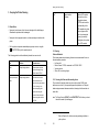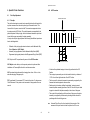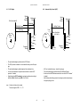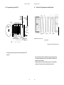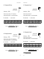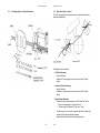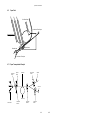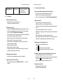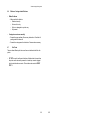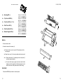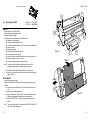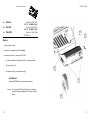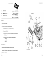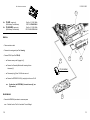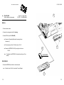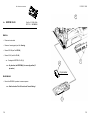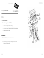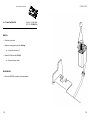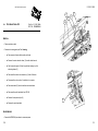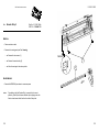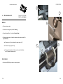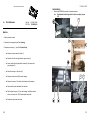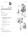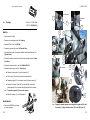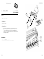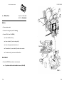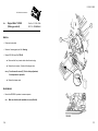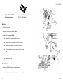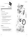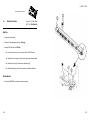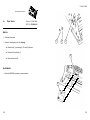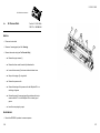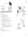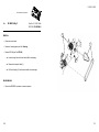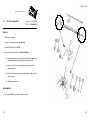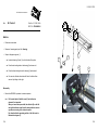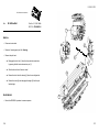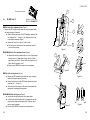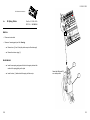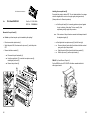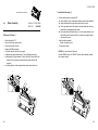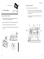
1
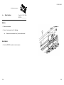
LA600 MultiPrinter
Field Service Manual
The information in this document is subject to change without notice and should not be construed as a
commitment by Digital Equipment Corporation. Digital Equipment Corporation assumes no
responsibility for any errors that may appear in this document.
Copyright © by Digital Equipment Corporation 1998.
All rights strictly reserved. Reproduction or issue to third parties in any form is not permitted without
written authorization from the publisher.
Order No.: ER-LA600-SV
Pub. No. 5112 991 12933
November 1998
Table of Contents
Table of Contents
5. Printer Subassemblies . . . . . . .
5.1 Basic Elements of the Printer
5.2 Main Subassemblies . . . . . . .
5.3 Internal Wiring Scheme . . . . .
.
.
.
.
.
.
.
.
.
.
.
.
.
.
.
.
.
.
.
.
.
.
.
.
.
.
.
.
.
.
.
.
.
.
.
.
.
.
.
.
.
.
.
.
.
.
.
.
.
.
.
.
.
.
.
.
.
.
.
.
.
.
.
.
.
.
.
.
.
.
.
.
.
.
.
.
.
.
.
.
.
.
.
.
.
.
.
.
.
.
.
.
.
.
.
.
.
.
.
.
.
.
.
.
.
.
.
.
.
.
.
.
.
.
.
.
5-1
5-1
5-2
5-3
6. Built In Diagnostics and Trouble Shooting
How to use this Section . . . . . . . . . . . . . . . . .
6.1 Power related Problems . . . . . . . . . . . . .
6.2 Error Messages . . . . . . . . . . . . . . . . . . . .
6.3 No Printout . . . . . . . . . . . . . . . . . . . . . . .
6.4 Operator related Problems . . . . . . . . . . .
6.5 Print related Problems . . . . . . . . . . . . . . .
6.6 Ribbon or Carriage-related Problems . . .
6.7 Print Tests . . . . . . . . . . . . . . . . . . . . . . .
.
.
.
.
.
.
.
.
.
.
.
.
.
.
.
.
.
.
.
.
.
.
.
.
.
.
.
.
.
.
.
.
.
.
.
.
.
.
.
.
.
.
.
.
.
.
.
.
.
.
.
.
.
.
.
.
.
.
.
.
.
.
.
.
.
.
.
.
.
.
.
.
.
.
.
.
.
.
.
.
.
.
.
.
.
.
.
.
.
.
.
.
.
.
.
.
.
.
.
.
.
.
.
.
.
.
.
.
.
.
.
.
.
.
.
.
.
.
.
.
.
.
.
.
.
.
.
.
.
.
.
.
.
.
.
.
.
.
.
.
.
.
.
.
.
.
.
.
.
.
.
.
.
.
.
.
.
.
.
.
.
.
.
.
.
.
.
.
.
.
.
.
.
.
.
.
.
.
.
.
6-1
6-1
6-2
6-2
6-5
6-6
6-7
6-9
6-9
1. Introduction . . . . . . . . . . . . . . . . . . . . . . . . . . . . . . . . . . . . . . . . . . . . 1-1
2. Safety Precautions . . . . . . . . . . . . . . . . . . . . . . . . . . . . . . . . . . . . . . . 2-1
3. Keeping the Printer Running . . . . . . . . . . . . . . .
3.1 Basic Rules . . . . . . . . . . . . . . . . . . . . . . . . . .
3.2 Cleaning . . . . . . . . . . . . . . . . . . . . . . . . . . . . .
3.2.1 Cleaning the Platen and Surrounding Areas
PRINT TEST 3 . . . . . . . . . . . . . . . . . . . . . . . . . .
3.2.2 Cleaning Procedures . . . . . . . . . . . . . . . . .
3.3 Status and Error Messages . . . . . . . . . . . . . .
.
.
.
.
.
.
.
.
.
.
.
.
.
.
.
.
.
.
.
.
.
.
.
.
.
.
.
.
.
.
.
.
.
.
.
.
.
.
.
.
.
.
.
.
.
.
.
.
.
.
.
.
.
.
.
.
.
.
.
.
.
.
.
.
.
.
.
.
.
.
.
.
.
.
.
.
.
.
.
.
.
.
.
.
.
.
.
.
.
.
.
.
.
.
.
.
.
.
.
.
.
.
.
.
.
.
.
.
.
.
.
.
3-1
3-1
3-2
3-2
3-3
3-4
3-5
4. Specific Printer Functions . . . . . . . . . . . . . . . . . . . . . .
4.1 Print Gap Ajustment . . . . . . . . . . . . . . . . . . . . . . . . .
4.1.1 Principle . . . . . . . . . . . . . . . . . . . . . . . . . . . . . . .
4.1.2 AGC Procedure . . . . . . . . . . . . . . . . . . . . . . . . . .
4.1.3 AGC Adjust . . . . . . . . . . . . . . . . . . . . . . . . . . . . .
4.1.4 Automatic Gap Control (AGC) . . . . . . . . . . . . . . .
4.1.5 Programmed Copy Control (PCC) . . . . . . . . . . . .
4.2 Print Head - Tilting Principle and related Print Speed
4.2.1 Print Speed in DATA (DRAFT) Mode . . . . . . . . . .
4.4.2 Print Speed in NLQ Mode . . . . . . . . . . . . . . . . . .
4.4.3 Print Speed in LQ Mode 1 . . . . . . . . . . . . . . . . . .
4.4.4 Print Speed in LQ Mode 2 . . . . . . . . . . . . . . . . . .
4.3 Positioning System - Horizontal Positioner . . . . . . . .
4.4 Paper Run / Paper In Control . . . . . . . . . . . . . . . . . .
4.5 Paper Path . . . . . . . . . . . . . . . . . . . . . . . . . . . . . . . .
4.5.1 Paper Transportation Principle . . . . . . . . . . . . . . .
.
.
.
.
.
.
.
.
.
.
.
.
.
.
.
.
.
.
.
.
.
.
.
.
.
.
.
.
.
.
.
.
.
.
.
.
.
.
.
.
.
.
.
.
.
.
.
.
.
.
.
.
.
.
.
.
.
.
.
.
.
.
.
.
.
.
.
.
.
.
.
.
.
.
.
.
.
.
.
.
.
.
.
.
.
.
.
.
.
.
.
.
.
.
.
.
.
.
.
.
.
.
.
.
.
.
.
.
.
.
.
.
.
.
.
.
.
.
.
.
.
.
.
.
.
.
.
.
.
.
.
.
.
.
.
.
.
.
.
.
.
.
.
.
.
.
.
.
.
.
.
.
.
.
.
.
.
.
.
.
.
.
.
.
.
.
.
.
.
.
.
.
.
4-1
4-1
4-1
4-2
4-3
4-4
4-5
4-6
4-7
4-7
4-8
4-8
4-9
4-10
4-11
4-11
I
II
Table of Contents
7. Procedures for Removal and Reassembly of Spare Parts
Housing 405 . . . . . . . . . . . . . . . . . . . . . . . . . . . . . . . . . . . . .
Top Cover LA600 . . . . . . . . . . . . . . . . . . . . . . . . . . . . . . . . .
Top Cover 405 . . . . . . . . . . . . . . . . . . . . . . . . . . . . . . . . . . .
Front Cover 405 . . . . . . . . . . . . . . . . . . . . . . . . . . . . . . . . . .
Front Insertion 405 . . . . . . . . . . . . . . . . . . . . . . . . . . . . . . . .
Stacker Support 405 . . . . . . . . . . . . . . . . . . . . . . . . . . . . . . .
Print Engine LA600 . . . . . . . . . . . . . . . . . . . . . . . . . . . . . . .
PSU-40A . . . . . . . . . . . . . . . . . . . . . . . . . . . . . . . . . . . . . . .
DEV-40AE . . . . . . . . . . . . . . . . . . . . . . . . . . . . . . . . . . . . . .
DEV-40A . . . . . . . . . . . . . . . . . . . . . . . . . . . . . . . . . . . . . . .
CU-40K . . . . . . . . . . . . . . . . . . . . . . . . . . . . . . . . . . . . . . . .
Print CU-40L . . . . . . . . . . . . . . . . . . . . . . . . . . . . . . . . . . . .
EEPROM CU-40X . . . . . . . . . . . . . . . . . . . . . . . . . . . . . . . .
Operator Panel 40B . . . . . . . . . . . . . . . . . . . . . . . . . . . . . . .
Power Switch 40A . . . . . . . . . . . . . . . . . . . . . . . . . . . . . . . .
Print Head Cable 405 . . . . . . . . . . . . . . . . . . . . . . . . . . . . . .
Encoder Stripe 2 . . . . . . . . . . . . . . . . . . . . . . . . . . . . . . . . .
Kit Lubrication Felt . . . . . . . . . . . . . . . . . . . . . . . . . . . . . . . .
Print H-Encoder . . . . . . . . . . . . . . . . . . . . . . . . . . . . . . . . . .
H-Motor . . . . . . . . . . . . . . . . . . . . . . . . . . . . . . . . . . . . . . . .
Carriage . . . . . . . . . . . . . . . . . . . . . . . . . . . . . . . . . . . . . . . .
Protection Schield . . . . . . . . . . . . . . . . . . . . . . . . . . . . . . . .
Ribbon Gear . . . . . . . . . . . . . . . . . . . . . . . . . . . . . . . . . . . .
Stepper Motor 7.5 DEG (Palten Gap Control) . . . . . . . . . . . .
Stepper Motor 1.8 DEG (Vertical Paper Transport) . . . . . . . .
Tractor Gear . . . . . . . . . . . . . . . . . . . . . . . . . . . . . . . . . . . .
Stacker Elements . . . . . . . . . . . . . . . . . . . . . . . . . . . . . . . . .
Paper Sensor . . . . . . . . . . . . . . . . . . . . . . . . . . . . . . . . . . . .
Kit Pressure Rolls . . . . . . . . . . . . . . . . . . . . . . . . . . . . . . . . .
.
.
.
.
.
.
.
.
.
.
.
.
.
.
.
.
.
.
.
.
.
.
.
.
.
.
.
.
.
.
.
.
.
.
.
.
.
.
.
.
.
.
.
.
.
.
.
.
.
.
.
.
.
.
.
.
.
.
.
.
.
.
.
.
.
.
.
.
.
.
.
.
.
.
.
.
.
.
.
.
.
.
.
.
.
.
.
.
.
.
.
.
.
.
.
.
.
.
.
.
.
.
.
.
.
.
.
.
.
.
.
.
.
.
.
.
.
.
.
.
.
.
.
.
.
.
.
.
.
.
.
.
.
.
.
.
.
.
.
.
.
.
.
.
.
.
.
.
.
.
.
.
.
.
.
.
.
.
.
.
.
.
.
.
.
.
.
.
.
.
.
.
.
.
.
.
.
.
.
.
.
.
.
.
.
.
.
.
.
.
.
.
.
.
.
.
.
.
.
.
.
.
.
.
.
.
.
.
.
.
.
.
.
.
.
.
.
.
.
.
.
7-1
7-2
7-2
7-2
7-2
7-2
7-2
7-4
7-6
7-8
7-8
7-10
7-12
7-14
7-16
7-18
7-20
7-22
7-24
7-26
7-28
7-30
7-32
7-34
7-36
7-38
7-40
7-42
7-44
7-46
III
Table of Contents
8
Kit V-Transport . . . . . .
Belt Stepper . . . . . . . .
Belt Form Feed . . . . . .
Kit Belt Pulley 2 . . . . .
Kit Cont. Form Exit . . .
Kit Tractor 2 . . . . . . . .
Kit H-Drive Belt . . . . . .
Kit ASF Lever 2 . . . . . .
Kit Spring D-Axis . . . .
Kit Screws and Springs
Noise Absorber . . . . . .
Rep Kit ASF-Cassette .
.
.
.
.
.
.
.
.
.
.
.
.
.
.
.
.
.
.
.
.
.
.
.
.
.
.
.
.
.
.
.
.
.
.
.
.
.
.
.
.
.
.
.
.
.
.
.
.
.
.
.
.
.
.
.
.
.
.
.
.
.
.
.
.
.
.
.
.
.
.
.
.
.
.
.
.
.
.
.
.
.
.
.
.
.
.
.
.
.
.
.
.
.
.
.
.
.
.
.
.
.
.
.
.
.
.
.
.
.
.
.
.
.
.
.
.
.
.
.
.
.
.
.
.
.
.
.
.
.
.
.
.
.
.
.
.
.
.
.
.
.
.
.
.
.
.
.
.
.
.
.
.
.
.
.
.
.
.
.
.
.
.
.
.
.
.
.
.
.
.
.
.
.
.
.
.
.
.
.
.
.
.
.
.
.
.
.
.
.
.
.
.
.
.
.
.
.
.
.
.
.
.
.
.
.
.
.
.
.
.
.
.
.
.
.
.
.
.
.
.
.
.
.
.
.
.
.
.
.
.
.
.
.
.
.
.
.
.
.
.
.
.
.
.
.
.
.
.
.
.
.
.
.
.
.
.
.
.
.
.
.
.
.
.
.
.
.
.
.
.
.
.
.
.
.
.
.
.
.
.
.
.
.
.
.
.
.
.
.
.
.
.
.
.
.
.
.
.
.
.
.
.
.
.
.
.
.
.
.
.
.
.
.
.
.
.
.
.
.
.
.
.
.
.
.
.
.
.
.
.
.
.
.
.
.
.
.
.
.
.
.
.
.
.
.
.
.
.
.
.
.
.
.
.
.
.
.
.
.
.
.
.
.
.
.
.
.
.
.
.
.
.
.
.
.
.
.
.
.
.
.
.
.
.
.
.
.
.
.
.
.
.
.
.
.
.
.
.
.
.
.
.
.
.
.
.
.
.
.
.
.
.
.
.
.
.
.
.
.
.
.
.
.
.
.
.
.
.
.
.
.
.
7-48
7-48
7-48
7-50
7-52
7-54
7-56
7-58
7-60
7-62
7-64
7-66
Wearing Parts . . . . .
Print Head DH3024/2
Platen Assy . . . . . . .
ASF Pick-up Rollers .
.
.
.
.
.
.
.
.
.
.
.
.
.
.
.
.
.
.
.
.
.
.
.
.
.
.
.
.
.
.
.
.
.
.
.
.
.
.
.
.
.
.
.
.
.
.
.
.
.
.
.
.
.
.
.
.
.
.
.
.
.
.
.
.
.
.
.
.
.
.
.
.
.
.
.
.
.
.
.
.
.
.
.
.
.
.
.
.
.
.
.
.
.
.
.
.
.
.
.
.
.
.
.
.
.
.
.
.
.
.
.
.
.
.
.
.
.
.
.
.
.
.
.
.
.
.
.
.
.
.
.
.
.
.
.
.
.
.
.
.
.
.
.
.
.
.
.
.
.
.
.
.
8-1
8-2
8-4
8-6
9. List of Spare Parts, Wearing Parts, and Tools . . . . . . . . . . . . . . . . . . 9-1
9.1 List of Spare Parts . . . . . . . . . . . . . . . . . . . . . . . . . . . . . . . . . . . . . . . . 9-1
9.2 List of Wearing Parts . . . . . . . . . . . . . . . . . . . . . . . . . . . . . . . . . . . . . . 9-3
IV
Introduction
1. Introduction
proper handling of the wearing parts of the printer.
9
The manual is divided into the following chapters:
1
Introduction
This chapter gives an overview about the manual and some basic
informations.
2
Safety Precautions
This chapter contains all the important instructions a service technician
should obey during a service action.
3
Keeping the Printer Running
This chapter instructs the user about preventive meassures for troublefree
operation of the printer.
4
Specific Printer Functions
This chapter describes some basic functions of the printer, which should be
known by persons who are performing the technical support for this
product.
5
Printer Subassemblies
This chapter comprises diagrams, depicturing the printer´s subassemlies,
the internal wiring scheme and arrangement of the collective connectors.
6
Built In Diagnostics and Trouble Shouting
This chapter gives a description of some problem symptoms and how to
isolate the failures with regard to spare parts and field replaceable units
concerned.
7
Procedures for Removal and Reassembly of Subassemblies and
Spare Parts
This chapter contains all removal and reassembly procedures for an onsite- or workshop-repair of the printer.
8
Wearings Parts
This chapter describes the removal procedures which are necessary for
1-1
1-2
List of Spares and Repairs
This chapter lists all actually defined Spare Parts and Wearing Parts and
contains the relevant reference to the different chapters of this manual as
far as requested.
2. Safety Precautions
S Some of the maintenance procedures described in this section require that
the printers top housing is removed. This exposes the internal working parts
of the printer. During operating touching some of these parts may be
potentially dangerous.
S All replacement and cleaning procedures should be performed with the
printer switched OFF and the mains connector disconnected.
S Only recommended parts should be used to replace defective parts. Details
of field exchangeable parts, including part number and order number are
listed in Chapter 9.
S Switch the printer OFF while connecting or disconnecting a Personality
Module.
S Don´t touch the print head after long peroids of printing, because it can be
very hot.
2-1
2-2
Keeping the Printer Running
3. Keeping the Printer Running
ASF 1)
Paper insertion
problems
3.1 Basic Rules
S Never print over the area of pin holes nor the edges of the fanfold paper.
Otherwise the print head can be damaged.
S Never print with no papaer loaded or no ribbon cartridge is installed in the
printer.
Remove ASF cassette.
Clean pick-up rollers
using platen cleaner
S/CP 09, and check the
paper handling of the
ASF cassette using a few
sheets of paper which
have to be transported
properly by manually
rotating the pick-up wheel
of the ASF-cassette.
S Put the printer in stop mode immediately a paper jam occurs, using the
[START/STOP] key at the operator pannel.
3.2 Cleaning
Preferred Materials
The following materials and cleaning lubricants are recommended for use in
the maintenance procedure:
S Lint-free cloth
S Platen Cleaner C/CP09, commercial no: 8709 004 10931
S Vacuum cleaner
S Silicon Oil for resolving of glue.
The following points should be additionally checked on a service call.
Item
Problem
Remedial Action
Platen
Paper feeding problems
Remove platen and clean
surface thoroughly using
platen cleaner S/CP 09.
Paper input transport
rollers
Paper feeding problems
Disconnect mains cable,
remove the ribbon, and
remove housing (see chapter
3, Part: Housing). Also
remove the paper guide
secured with two green
3.2.1 Cleaning the Platen and Surrounding Areas
The user should clean the printer every six months or after 50,000 prints,
whichever occurs first. If you experience paper feed problems, or if the print
head carriage movement becomes restricted, cleaning should be carried out
more often.
screws. Clean all transport
Note:
rollers using platen cleaner
S/CP 09.
The Page Counter (PGCNT) in the PRINT-TEST 3 will inform you about
the actual number of printed pages.
1)
3-1
3-2
Refer to Chapter 4 to check a necessary exchange of platen or
pick-up rollers.
Keeping the Printer Running
PRINT TEST3
3.2.2 Cleaning Procedure
CONFIGURATION
PM1
SPC
MCR
NFQ
TNA1
PTC1
PHCS2
208xxxxx
2080740x
0
1800
230
2.75
1.00
1. Power the printer ON and remove the top cover.
PM2
MC
DSF
TNA2
PTC2
PGC
C020 DEC NCR SETS
C023 DEC TECHNICAL
Note:
Keeping the Printer Running
00000000
00000000
100
260
2.85
30
PM3
CUR
208079xx
4
GSF
TNA3
PTDT
PGCNT
C021 DEC SUPPLEMENT
C024 DEC 7 HEBREW
70
260
5
25
PBC
PMR
NTF
CAC
PHCS1
SBP
20807xxx
0
240
3.10
2.20
38
C022 DEC SPEC GRAP
.... ... ....
The number following PM1 identifies the micro program and the number
following PM3 identifies the character set.
2. Remove the ribbon cassette.
3. Thoroughly brush and vacuum all accessible areas to remove any paper
flock and dust.
4. Clean the platen's surface, the paper pressure rollers and the transport
rollers using the platen cleaner. In order to access the transport rollers
loosen the green screws and remove the metal bar with the metal rollers.
5. Clean the covers and the operator panel with a damp, lint-free cloth. Do not
use cleaning solvents or excessive amounts of water.
6. Insert the ribbon cassette.
7. Remount the top cover.
3-3
3-4
Keeping the Printer Running
3.3
Status and Error Messages
TEAR OFF PAPER
Displayed when a switch has been initiated from currently tractor to a different
paper source and the fanfold paper could not retreat into the parking position.
The operator must "tear off" the paper along the tear off edge which is located
directly above the fanfold paper output (paper should be torn off from left to
right). Press
to enable the fanfold paper to be fed backwards to a park
position so that the newly selected paper source can be used.
The following messages are displayed if a condition exists which prevents
normal operation of the printer.
LOCAL
Entered when
Keeping the Printer Running
[START/STOP] was pressed. The STOP indicator is lit.
COVER OPEN
Displayed when the top cover is open and the printer is in the READY or BUSY
mode.
LOAD BIN
Displayed whenever a form feed command or print command is given by the
host to an empty ASF cassette. The printer enters the STOP mode.
LOAD TRACTOR
Displayed when the host sends a form feed or print command to an empty
tractor cassette. The printer enters the STOP mode.
REMOVE PAPER
This message will be displayed if the output for cut sheets (Bin or Manual) is
selected to FRONT SIDE/KEY. After printing and moving out at the front side
the printer enters the STOP mode and displays REMOVE PAPER. Remove
paper and press
.
During normal operation the following error messages may occur also:
Display
That means...
Cause / Action
AGC ERROR
AGC ADJUST
procedure fault
- Distance print head and
platen faulty
- Print head loose
- Platen incorrectly installed
- Ribbon not inserted
- Horizontal drive without
function
- Platen got dirty
LOAD MANUAL
Same as LOAD TRACTOR except that the machine does not enter the STOP
mode! Paper should be fed manually; after a short delay the printer will accept
paper and starts printing.
PAPER JAM TRF
PAPER JAM ASF
PAPER JAM MANUAL
Displayed if a form jams in the ASF or if successive line feeds fail to move
fanfold paper correctly when tractor feed is used.
3-5
3-6
Keeping the Printer Running
Display
That means...
Cause / Action
HOR. DRIVE ERROR
Horizontal drive
without function
- Horizontal drive blocked
- Paper jam
- Distance of platen gap too
narrow
- AGC procedure on not
workable position
- Platen incorrectly installed
- No AGC ADJUST after
print head or platen
replacement
- Device electronic fault
- Encoder strip missing
- Horizontal drive fault
BUFFER
OVERFLOW
Handshake
protocol error
- Check CTR - CTS or
XON - XOFF protocol
- Repeat data transfer
FORMAT ERROR
Protocol error
- Check protocol setting of
printer and host
- Repeat data transfer
PARITY ERROR
Protocol error
- Check protocol setting of
printer and host
- Repeat data transfer
FRAMING ERROR
Protocol error
- Check protocol setting of
printer and host
- Repeat data transfer
For mesages during power up refer to Section 6.2 Error Messages during
Power Up.
3-7
3-8
Specific Printer Functions
4. Specific Printer Functions
4.1
4.1.2 AGC Procedure
Print Gap Adjustment
Selected AGC Position
4.1.1 Principle
The print head carriage is mounted on two parallel guide rails which provide for
a precise movement over the whole print range in horizontal direction. The
lower rail is built up as an excentric shaft. The excentre arrangement is driven
by a stepper motor (AGC-Motor). Those both elements are responsible for the
precise adjustment of the print gap, that is the distance between the print head
top and the the paper respectively the platen assembly.
In conjunction with print gap adjustment the following three different procedures
have to be distinguished:
S
S
S
1 / 120 “
Horizontal Encoder
Lineal
Calibration of the print gap adjustment mechanics, called Automatic Gap
Control Adjustment (AGC Adjust)
Automatic print gap adjustment, called Automatic Gap Control (AGC)
Programmed print gap adjustment, called Programmed Copy Control (PCC)
1
3
2
4
1
2
AGC Adjust and AGC are performed by means of the AGC Procedure.
Movement Area of the Print Head
AGC Adjust can be called up via the operator panel and is performed after
installation of a Personality Module with a new firmware revision.
S
AGC is automatically performed after changing from online - offline – online,
and after changing of the paper path.
S
PCC is performed if the command PCC is sent to the printer. For refernce see
“Quick Reference” of the printer control commands in the appendix of the user
manual.
S
S
S
At the start the printhead/carriage is horizontally positioned at the AGC
Position
The carriage is permanently moved in horizontal direction by a distance of
1/120” to the left and right hand side of the AGC Position.
The time period for horizontal movement is permanently recognized by the
firmware and checked against a reference value.
Simultanously to the above shuttling the printhead / carriage is moved
towards the platen assembly by means of the AGC drive until the print head
top gets in contact with the platen assembly or the surface of the paper.
The contact of the printhead top with the surface of the paper or the platen
assembly is recognized by the firmware by checking the time interval for
positioning within the shuttling process.
Note:
4-1
4-2
Horizontal Drive Error will not be checked by this procedure. If the
movement of the print head is to hard the printer use 0.5 A more.
Specific Printer Functions
4.1.3 AGC Adjust
Specific Printer Functions
4.1.4 Automatic Gap Control (AGC)
Shuttle
Base
Position
No Form inserted !!
Shuttle
Base
Position
Mechanical
Stop
Mechanical
Stop
Positioning
Shuttling Process
Shuttling Process
Positioning
Form
Platen
Assy
Print
Head
Protection
Shield
S
S
S
S
S
Platen
Assy
Print
Head
Ribbon
Print Gap
The print head/carriage is positioned at the AGC Position
The AGC procedure is started. It can be started from any value of the print
gap.
The print head/carriage is positioned against the mechanical stop
As soon as the mechanical stop has been reached the so called “AGC
procedure” is started
After finishing the AGC Procedure the carriage is positioned according to
the Shuttle Basis Posisition (see SBP in Print Test 3).
Note:
Platen Gap Adjust
(-3 ... +4)
S
S
S
S
No form, but ribbon to be inserted.
Tolerance range for SBP: -12 ... +72.
4-3
4-4
Protection
Shield
Ribbon
AGC can be started from any value of the print gap.
The print head/carriage is positioned at the Shuttle Basis Position
As soon as the the SBP has been reached, the so called “AGC Procedure”
is started
After finishing the shuttling process the carriage is positioned according to
the proper print gap value
Specific Printer Functions
4.1.5 Programmed Copy Control (PCC)
4.2
Shuttle
Base
Position
Form
Specific Printer Functions
Print Head - Tilting Principle and related Print Speed
Mechanical
Stop
Positioning Process
Platen
Assy
Print
Head
Ribbon
Print Gap
Platen Gap Adjust (-3 ... +4)
PCC:
1
2
3
4
5
Inclination Position for LQ mode
Protection
Shield
no print position
6
Inclination Position for DATA or NLQ mode
S
The print gap is set according to the value commanded by the PCC
command.
S
S
4-5
4-6
The nose of the print head can be tilted according to the scheme above.
The different tilting positions are used for realizing of the different print
speeds and print resolutions.
Switching between both print head tilting positions is accomplished by
positioning of the carriage to ist most right hand side position.
Specific Printer Functions
4.2.1 Printing Speed in DATA mode
Specific Printer Functions
3)
4.2.3 Printing Speed in LQ mode 1
Inclination Position
of the Print Head Lug
Needle frequency
Inclination Position
of the Print Head Lug
1.800 Hz
Needle frequency
1.800 Hz
Number of columns per character: 12, 2x 12 needles in use
Number of needles per character: 3, each other needle activated
Number of columns per character: 36
Number of needles per character: 12, each 3rd needle activated
M = needle activated
M = needle activated
F = needle not activated
F = needle not activated
1
2
3
4
5
6
7
8
9
10
11
12
1
2
3
4
5
6
..
..
..
24
35
36
M
F
M
F
M
F
M
F
M
F
M
F
M
F
F
M
F
F
M
F
F
M
F
F
Print Speed '
Needle Strokes per Second
1800
'
' 600 cps
Number of Needles per Character
3
Print Speed '
Needle Strokes per Second
1800
'
' 150 cps
Number of Needles per Character
12
4.2.4 Printing Speed in LQ mode 2 3)
4.2.2 Printing Speed in NLQ mode
Inclination Position
of the Print Head Lug
Inclination Position
of the Print Head Lug
Needle frequency
Needle frequency
1.800 Hz
Number of columns per character: 36
Number of needles per character: 18, each other needle activated
1.800 Hz
Number of columns per character: 36, 2x 12 needles in use
Number of needles per character: 6, each 3rd needle activated
M = needle activated
1
M
2
F
3
F
Print Speed '
M = needle activated
F = needle not activated
4
M
5
F
6
F
..
M
..
F
..
F
34
M
35
F
36
F
1
2
3
4
5
6
..
..
..
34
35
36
M
F
M
F
M
F
M
F
M
F
M
F
Needle Strokes per Second
1800
'
' 300 cps
Number of Needles per Character
6
Print Speed '
3
4-7
F = needle not activated
4-8
Needle Strokes per Second
1800
'
' 100 cps
Number of Needles per Character
18
depending on the selected font
Specific Printer Functions
4.3
Positioning System - Horizontal Positioner
Specific Printer Functions
4.4
Paper Run / Paper In Control
The printer is equipped with a combined paper run/in feature realized by the
sensor as depicted below.
Following functions are realized:
S
Cut Sheet Processing
S Paper In Detection
Detection of the upper edge of the form by means of the “Paper In”
feature
S
Continuous Forms Processing
S Paper In Detection
Detection of the upper edge of the form by means of the “Paper In”
feature
S
Paper Movement Detection
S Detection of paper movement by means of the “Paper Run” feature
S Check on missing paper run pulses by time out
S Tolerance range is in between 10,5 mm up to 19 mm
S
S
4-9
4-10
Counting of paper run pulses and comparison with the equivalent value
according to the internal positioning command
Evaluation of both criterions after each positiong process
Specific Printer Functions
4.5
Paper Path
Cut Sheet Ouput
Continuous Form Output
Automatic Sheet
Feeding
Paper Sensor
Manual Input
Continuous Form Input
4.7.1 Paper Transportation Principle
Paper Run
Sensor
Paper In
Sensor
Stacker Exit
Rollers
Print Head
Stacker
Manual
Tear Off
Platen Assy
Park Position
Form Feed
Rollers 1
Form Feed
Rollers 2
Tractor Exit
Rollers
4-11
4-12
Printer Subassemblies
5. Printer Subassemblies
5.2 Main Subassemblies
The main subassemblies are:
S Mechanical Subassembly (A)
5.1 Basic Elements of the Printer
The printer contains of the following use accessable parts:
S Electronic Subassembly (B)
S Power Supply Unit (PSU-40A)
S Control Unit (Print CU-40L)
S Device Electronics (DEV-40AE)
6
1
2
A
3
4
6
5
B
7
- Top Cover (1)
- Printer Engine including Electronic Subassembly (3)
- Manual Front Insertion Guide (5)
- Personality Module (likewise named PM) (7)
- Ribbon Cassette (2)
- Front Cover (4)
- Output Stacker (6)
You are able to disassembly each part without any tools.
5-1
5-2
Printer Subassemblies
5.3 Internal Wiring Scheme
5-3
5-4
Troubleshooting and Diagnostics
6
Troubleshooting and Diagnostics
6.1
S
S
Power indicator does not come On when power is switched On
Check that the power cord and plug are securely fitted to the printer and to
an electrical outlet.
Ask for the power connector connections (and fuse, if fitted) to be verified.
Ask for the building electrical supply to be verified.
S
S
How to Use This Section
1. Find the category in which your problem occurs. The problem categories
are:
S Power-related Problems
S Error Messages
S No Printout
S Operation-related Problems
S Print-related Problems
S Ribbon or Carriage-related Problems
Power-related Problems
6.2
Error Messages
After switching the power ON the printer runs a self test. During the test the
following messages may be shown on the display:
For example, if the print appears very light on the paper, look at Section "Printrelated Problems".
2. Find the symptom description that most closely matches the printer
symptom. In this example you would look at the symptom "Print faint
or of poor quality."
3. Try the first suggestion under that heading.
4. If the suggestion does not cure the problem, try the next suggestion.
5. If none of the suggestions enable you to continue printing, or if the fault
is not listed, contact your service office.
Each time the printer is switched ON the display indicates TEST while the
internal self-tests are run. If the test is completed successfully READY 4 ELQ
will be displayed. If an error message is displayed please refer to the following
section. All other messages on the display are described in section 2.4 Status
and Error Messages.
6-1
Display
That means ...
Cause / Action
No
information,
POWER ON
indicator not
lit.
No power
- Mains cable not connected
- Mains switch cable not
connected
green and
yellow LED
give light but
no reaction
hang up in reset after
power on
- Print PSU defective
- Print CU-DEV defective
########
Firmware does not
work
- PM not inserted
- PM not correctly inserted
- no firmware on PM
- PROMs not correctly installed
TEST....
(flashing)
Initializing of the
EEPROM
- After first POWER ON
with new firmware (different
code number
- Contents of the EEPROM
faulty
I/O OK
EEPROM located on
the Control Unit not
addressable
EEPROM
- not installed
- not correctly installed
- defective
6-2
Troubleshooting and Diagnostics
Display
That means ...
Cause / Action
NV RAM OK
Error on the RAM of
the Control Unit
- Control Unit defective
RAM OK
Checksum error
- (P)ROM defective
ROM 1 OK
No Fonts available
- Character generator P(ROM)
on PM damaged or missing
ROM 2 OK
IC damaged
- IC on 3. socket defective
MC OK
Fault on Control Unit
- Control Unit defective
- false firmware release
- PBC (Printer Base
Controller) on Control Unit
damaged
- SPC (Speed Controller)
on Control Unit damaged
Troubleshooting and Diagnostics
During normal operation the following error messages may occur (for further
operator panel messages please refer to section 3.3 Status and Error
Messages):
Display
That means...
Cause / Action
AGC ERROR
AGC ADJUST
procedure fault
- Distance print head and
platen faulty
- Print head loose
- Platen incorrectly installed
- Ribbon not inserted
- Horizontal drive without
function
- Platen got dirty
HOR. DRIVE ERROR
Horizontal drive
without
function
- Transport lock not removed
- Horizontal drive blocked
- Paper jam
- Distance of platen gap too
narrow
- AGC procedure on not
workable position
- Platen incorrectly installed
- No AGC ADJUST after
print head or platen
replacement
- Device electronic fault
- Encoder strip missing
- Horizontal drive fault
BUFFER
OVERFLOW
Handshake
protocol error
- Check protocol setting of
printer and host
- Repeat data transfer
PARITY ERROR
Protocol error
- Check protocol setting of
printer and host
- Repeat data transfer
If all tests have been passed successfully the following message will be
displayed:
Display
That means...
Cause / Action
READY/BUSY
The Printer is OK
- Printer ready for
operation
6-3
6-4
Troubleshooting and Diagnostics
FRAMING ERROR
6.3
Protocol error
Troubleshooting and Diagnostics
6.4
- Check protocol setting of
printer and host
- Repeat data transfer
S
Paper is not positioned at perforation for tear-off feature
S Select the correct form length using the Set-up feature.
S Reset top of form by performing a Parking function.
S Refer to User´s Manual section 3.4 Vertical Positioning Adjustment
S
Paper tears or jams
S Examine the paper path; remove any obstructions
S Is the paper too loose or too taut between the tractors?
If the holes in the paper are deformed at their outer edges, the paper is
too taut.
If the paper rises between the tractors, it is too loose.
Readjust the tractor spacing so that the paper lies smoothly but without
any tension.
Ensure that the paper is horizontally aligned on the pins.
S Open the printer's top cover. If necessary, loosen the two green screws
and remove the paper guide plate to gain access to the paper.
S
Parking paper and resetting top of form
S Tear off the paper at the perforation line.
S Press
.
S Press
until the paper is in the park position.
S Press
. Printing will resume at the top of the next form.
S
Print head carriage does not move smoothly/does not move at all
S Examine the paper pathway. Remove any obstructions.
S Examine the carriage area for obstructions. Remove, where necessary.
Press the key
when the paper pathway is cleared.
S Make sure that the transport lock has been removed.
S
Single sheets are skewed
S Adjust manual paer insertion guide.
S Adjust ASF cassette paper guides.
No Printout
S
Self-test printout does not start
S Make sure that you have closed the cover.
S Check if paper is loaded in the printer.
S
Printing does not start
S Make sure that the READY or BUSY message is displayed. If there is a
different message displayed please refer to the above error message
table or to section 3.3 Status and Error Messages.
S Make sure that the printer is connected to the host computer. Make sure
that connectors are properly fixed at both ends.
S Make sure that the printer is receiving data from the host computer.
S Make sure that the correct protocol is enabled.
S Make sure that you have selected the correct port (if the automatic
feature has not been selected).
S Make sure that paper is loaded.
S Make sure that the ribbon is installed.
S Examine the ribbon path. Does the ribbon pass in front of the whole
printhead? Adjust the ribbon if necessary.
S
Fanfold paper does not advance
S Make sure that the fanfold paper source tractor is selected.
S
Single sheet paper does not advance
S Make sure that the paper source MANUAL or BIN x (x = 1 up to 3) is
selected.
6-5
Operation-related Problems
6-6
Troubleshooting and Diagnostics
6.5
S
Print-related Problems
Troubleshooting and Diagnostics
If the printout or the character set is not ok, the following procedure can help to
clear the situation.
Print faint or of poor quality.
S Have you used the correct paper? See User´s Manual Chapter 7
Technical Data which contains a full specification of the paper you
can use. Replace the paper if it does not match the specification.
S Make sure that the ribbon is stretched correctly.
S Does the ribbon need changing? Replace it with a new ribbon if
necessary.
S Is the ribbon cartridge properly installed? Adjust as necessary.
Action
S
Characters do not print evenly or are not uniform in pitch
S Examine the paper pathway for dirt or other obstruction that may cause
the gap between print head and platen to vary. Remove the obstruction.
S
Print lines overlap
S Examine the paper pathway for dirt or other obstructions that may
prevent the platen from rotating freely. Remove the obstruction.
S
On preprinted forms, the printing on the copies is not aligned with the
preprinted matter
S Refer to User´s Manual section 3.4. Vertical Positioning
(VERT.POS.ADJ.)
S
Part of printed text is missing (loss of data)
S If you are using Serial communications check the buffer control setting
in Set-up.
S Check the data flow control setting on the host computer.
6-7
Result
Check
Select and start PRINT Print not OK?
TEST 1
- PAPER SOURCE
selection
- Ribbon tension and
condition
- Print head condition
Stop SELF TEST and
start external printing
No printing starts
- Printer ONLINE
READY
- Interface cable for
proper connection
- Interface selection
Some characters not
correct
- Emulation
- Character set
- National version
- Word length
- Baud rate
- Parity bit
- Protocol
Font and pitch quality
fault
- Font
- Pitch
- Line space
6-8
Troubleshooting and Diagnostics
6.6
Ribbon or Carriage-related Problems
S
Ribbon Problems
S Make sure that the ribbon is:
S Stretched correctly
S Not worn thin or dry
S Not torn or damaged in any other way
S Not jammed
S
Carriage does not move smoothly
S Examine the paper pathway. Remove any obstructions. Check that all
packing material is removed.
S Examine the carriage area for obstructions. Remove where necessary.
6.7
Print Tests
There are three different print tests as well as one interface test built into the
printer.
S
I/F TEST is used to test the serial interface. It initiates data to be sent from
the printer and be returned by means of a closed loop connector plugged
into the serial interface connector. The test data used consists of PRINT
TEST 1 .
6-9
6-10
7. Procedures for Removal and Reassembly
This chapter describes the removal procedures which are necessary for proper
handling of the spare parts and subunits of the printer.
For detailed order information and description of the spare parts please refer to
the Spare Part Catalog (5112 991 1030x).
Note:
All removal procedures consists of several steps indicated with a:
" to show preparation and
Y
1
7-2
M
to indicate the main removal steps.
5112 991 10786
DEC Field Service Instruction
Part:
Housing 405 (1)
Part:
Top Cover LA600 (2)
Part:
Top Cover 40A (2) (PP 405)
Part:
Front Cover 405 (3)
Part:
Front Insertion 405 (4)
Part:
Stacker Support 405 (5)
Part No.: 5112 292 3840x
DEC P/N.: FD-W03RF-01
Part No.: 5112 292 6826x
DEC P/N.: 29-31800-01
Part No.: 5112 292 6827x
DEC P/N.: FD-W03RH-01
Part No.: 5112 212 5490x
DEC P/N.: FD-W03RC-01
Part No.: 5112 292 3842x
DEC P/N.: FD-W03RJ-01
Part No.: 5112 212 5500x
DEC P/N.: FD-W03RD-01
5
2
1
REMOVAL
" Disconnect mains cable
6
" Remove the manual front insertion (4)
Y
M
Remove the front cover (3) resp. the ASF cassette(s) out of the
mounting slots
Y
M
Swing the top cover (2) to its nearly upright position and remove it
Y
M
a) Remove the housing (1) by releasing the cover snap locks (6)
with a flat bladed screwdriver
3
b) To remove the housing (1) grasp it by the sides, raise the front
slightly, push the housing back until the metal snaps are out of
the slots at the rear of the printer and then lift the housing
4
REASSEMBLY
Execute the REMOVAL procedure in reverse sequence
7-2
7-3
5112 991 13242
DEC Field Service Instruction
7
3
Part:
Print Engine LA600
Part No.: 5112 292 6475x
DEC P/N.: 29-31790-01
REMOVAL
" Set the printer into "LOCAL MODE"
" Disconnect the system interface cable
" Remove the ribbon cartridge
" Switch the printer off and disconnect the mains cable
Y M Remove all encasing parts
Y M Remove the personality module (1)
Y M If present remove the plastic insert of the memory card interface (2)
Y M Loosen screw (3)
Y M Remove screws (4)
Y M Disconnect the Device Electronic (5)
Y M Disconnect the Control Unit (6)
Y M Loosen the fixation screws of the power on switch and remove it (7)
Y M Swivel the printer as shown in figure 2.
Y M Remove the safety angle by removing srew (8).
Note:
For protection of the operator panel please use a part of the
packaging material of the new printer engine as support.
Y
Y
Shift the entire Electronic Subassembly to the left. (Step 1)
Swivel it in the direction towards you and remove it from the printer
engine. (Step 2)
M
M
REASSEMBLING
" Unpack the new printer engine
" Execute the REMOVAL procedure with the new printer engine in reverse
direction.
Y M Change the print head from the "old" printer engine into the "new"
one.
Y M Perform an AGC Adjust procedure
Y M Adjust the parameter "Paper In Adj." to the value indicated on the
field service instruction attached to the new printer engine.
Y M Perform "PRINT TEST 3" and check for proper operation of the
printer.
Note:
7-4
5
4
6
4
Figure 1
2
1
Step 2
Step 1
8
Figure 2
Take a note of the value of the page counter (PGCNT) on the FRUlabel of the new printer engine.
7-5
5112 991 10415
DEC Field Service Instruction
Part:
PSU-40A
Part:
PSU-40D
Part:
PSU-40DS
Part No.: 5112 292 3811x
DEC P/N.: FD-W028Y-01-A01
Part No.: 5112 292 7627x
DEC P/N.: FD-W028Y-01-A02
Part No.: 5112 292 7628x
DEC P/N.: n. a.
2
4
REMOVAL
" Disconnect mains cable
" Remove all encasing parts (see Part: Housing)
" Loosen the two screws (1) securing the PSU-40A
Y
M
Lift the complete Power Supply Unit (PSU), using a screw driver
Y
M
Disconnect plug (3)
Y
M
Remove clamp (4) and disconnect plug (2)
3
REASSEMBLING
Execute the REMOVAL procedure in reverse sequence
Attention:
7-6
Do not touch the PSU board within min. 2 minutes after
power OFF before exchanging the PSU, please check the
fuse (5)
1
5
7-7
5112 991 12902
DEC Field Service Instruction
Part:
DEV-40AE
Part:
DEV-40A (PP 405) *)
Part:
DEV-40LA600 *)
Part No.: 5112 292 7159x
DEC P/N.: 29-31791-01-A02
Part No.: 5112 292 3810x
DEC P/N.: FD-W00CS-01
Part No.: 5112 292 6292x
DEC P/N.: 29-31791-01-A01
Detail A
1
7
REMOVAL
8
" Disconnect mains cable
" Remove all encasing parts (see Part: Housing)
Y
M
Loosen the two screws (1) and remove screw (2)
Y
M
Remove the DEV-40
a) while removing, DEV-40 (3) is automatically disconnected from
CU-40 (4)
b) disconnect all plug connections from the DEV-board:
S plug (5)
S plug (6)
S plug (7)
2
8
REASSEMBLING
6
Wire (8) has to be fastened by screw (2) as shown in Detail A
5
1
3
" Execute the REMOVAL procedure in reverse sequence
Attention:
4
see Detail A
*) End of Life, repair only
7-8
7-9
5112 991 16261
DEC Field Service Instruction
3
Part:
Part:
CU-40K (repair only)
(With Memory Card interface)
CU-40LA600 (repair only)
(With Memory Card interface)
Part No.: 5112 292 3885x
DEC P/N.:FD-W00CW-01
Part No.: 5112 292 6299x
DEC P/N.:29-31792-01-A1
REMOVAL
" Disconnect mains cable
" Remove all encasing parts (see Part: Housing)
" Remove DEV-40 (see Part: DEV-40)
1
Y
M
Remove memory card if plugged in (1)
4
Y
M
Remove the Personality Module after loosening the two
lockscrews (2)
IC pin marker
Y
M
Disconnect plug (3) from CU-40-K and remove it
Y
M
Remove the EEPROM CU 40X (4) and plug it into the new CU-40.
Note:
2
Pay attention, that EEPROM (4) is inserted correctly (see
IC pin marker)
REASSEMBLING
4
" Execute the REMOVAL procedure in reverse sequence
Note:
7-10
Start the function 'Print Out' and check 'Current Settings'
7-11
5112 991 16262
DEC Field Service Instruction
Part:
Print CU-40L
(Without Memory Card interface)
2
Part No.: 5112 292 7383x
DEC P/N.: 29-31792-01-A2
REMOVAL
" Disconnect mains cable
" Remove all encasing parts (see Part: Housing)
" Remove DEV-40 (see Part: DEV-40AE)
Y
M
Remove the Personality Module after loosening the two
lockscrews (1)
Y
M
Disconnect plug (2) from CU-40 and remove CU-40
Y
M
Remove the EEPROM CU 40X (3) and plug it into the new
CU-40 L.
Note:
Pay attention, that EEPROM (3) is inserted correctly (see IC pin
marker)
1
3
IC pin marker
REASSEMBLING
" Execute the REMOVAL procedure in reverse sequence
Note:
Start the function 'Print Out' and check 'Current Settings'
3
7-12
7-13
5112 991 11244
DEC Field Service Instruction
2
Part:
EEPROM CU-405
Part No.: 5112 000 4164x
DEC P/N.: 29-31802-01
REMOVAL
"
Disconnect mains cable
"
Remove all encasing parts (see Part: Housing)
"
Remove DEV-40 (see Part: DEV-40)
"
Remove CU-40 (see Part: CU-40)
Y
M
Exchange the EEPROM CU-40X (4)
Note:
1
3
Pay attention, that EEPROM (4) is in correctly position (IC
pin marker)
IC pin marker
REASSEMBLING
"
Execute the REMOVAL procedure in reverse sequence
Note:
Start the function 'Print Out' and check 'Current Settings'
3
7-14
7-15
5112 991 10494
DEC Field Service Instruction
Part:
Operator Panel 40B
Part No.: 5112 292 6418x
DEC P/N.: FD-W00CU-01
2
REMOVAL
3
"
Disconnect mains cable
"
Remove all encasing parts (see Part: Housing)
Y
M
Disconnect the Operator Panel cable (1)
Y
M
Loosen the screw (2) located at the bottom of the Operating Panel
Y
M
Remove the Operator Panel
REASSEMBLING
"
Execute the Removal procedure in reverse sequence
Note:
7-16
Remove the protection foil (3) from the Operator Panel installed
before mounting the housing
1
7-17
5112 991 10713
DEC Field Service Instruction
Part:
Power Switch 40A
Part No.: 5112 292 3882x
DEC P/N.: FD-W02H3-01
1
REMOVAL
"
Disconnect mains cable
"
Remove all encasing parts (see Part: Housing)
Y
"
M
Loosen the two screws (1)
Remove PSU-40x (see Part: PSU-40)
Y
M
Remove the power switch
REASSEMBLING
"
Execute the REMOVAL procedure in reverse sequence.
7-18
7-19
5112 991 10655
DEC Field Service Instruction
1
3
Part:
Print Head Cable 405
4
2
6
Part No.: 5112 292 3880x
DEC P/N.: FD-W02Y2-01
REMOVAL
" Disconnect mains cable
" Remove all encasing parts (see Part: Housing)
Y
M
Disconnect print head cable from the print head
Y
M
Remove the noise reduction foam (1) from the cable channel
Y
M
Clip the plastic support (2) from the print head carriage, by first
releasing clamps (3)
Y
M
Disconnect the wire-to-wire connection (4) of the H-Encoder
Y
M
Disconnect the colour option, if installed, incl. connector
Y
M
Disconnect cable (5) from the interface connection board
Y
M
Disconnect the print head cable from DEV-40
Y
M
Remove the two plastic clips (6)
Y
M
Remove the print head cable
5
REASSEMBLING
" Execute the REMOVAL procedure in reverse sequence
7-20
7-21
5112 991 10503
DEC Field Service Instruction
Part:
Encoder Strip 2
Part No.: 5112 292 7454x
DEC P/N.: FD-W041701
REMOVAL
" Disconnect mains cable
" Remove all encasing parts (see Part: Housing)
Y
M
Remove the two screws (1)
Y
M
Remove the encoder strip (2)
Y
M
Move the carriage to the centre position
Detail A
1
2
REASSEMBLING
" Execute the REMOVAL procedure in reverse sequence
Caution:
7-22
Pay attention, that the Encoder Strip is mounted in the correct
pistion by (Detail A) and observe that the strip is slipping under the
first two steel noses visible from the front side of the printer.
7-23
5112 991 12393
DEC Field Service Instruction
3
Part:
Kit Lubrication Felt
Part No.:5112 212 5589x
DEC P/N.: 29-31804-01
REMOVAL
2
" Disconnect mains cable
" Remove all encasing parts (see Part: Housing)
" Remove Encoder Strip (1) (see Part: Encoder Strip)
" Remove operator panel, but leave the interface cable connected (see Part:
Operator Panel)
Y
M
Remove srew (2) on both sides of the upper guide rail (3)
Y
M
Remove the upper guide rail (3)
Y
M
Exchange the lubrication felt (4). Insert the new felt with flatten
ear (5) towards the operator panel
4
5
REASSEMBLING
" Execute the REMOVAL procedure in reverse sequence
7-24
7-25
5112 991 10723
REASSEMBLING
" Execute the REMOVAL procedure in reverse sequence
Note: Pay attention that the logic cable is fixed correctly by clamp
(10)
DEC Field Service Instruction
2
Part:
Print H-Encoder
Part No.: 5112 292 4310x
DEC P/N.: FD-W0290-01
REMOVAL
" Disconnect mains cable
" Remove all encasing parts (see Part: Housing)
" Remove encoder strip (1) (see Part: Encoder Strip)
Y
M
Remove the noise reduction foam (2)
Y
M
Remove at the left and right side the upper screws (5)
Y
M
Loosen at the left and right side the screws (6) and remove the
mounting plate (7)
Y
M
Move the carriage to the cutout (8)
Y
M
Remove the two screws (9) from the carriage
Y
M
Remove the screw (10) and the cable clamp from the carriage
Y
M
Disconnect the print head cable from the head
Y
M
Clip the plastic support (11) from the carriage and disconnect the
wire-to-wire connector (12) H-Encoder/print head cable
Y
M
Remove the print head H-encoder
7-26
12
11
7-27
5112 991 10573
DEC Field Service Instruction
Part:
H-Motor
Part No.: 5112 292 3791x
DEC P/N.: FD-W0396-01
REMOVAL
" Disconnect mains cable
B
2
3
" Remove all encasing parts (see Part: Housing)
A
" Remove DEV-40 (see Part: DEV-40AE)
Y
M
Disengage the drive belt (1) from the drive wheel of the horizontal
motor by pressing the belt tension element (2), which is located at
the left side of the engine, upwards
Y
M
Pull off the belt from the wheel
Y
M
Disconnect the two pin motor cables (3) from the motors
connector (4) (see Detail A)
Y
M
Remove the two cables from the motor fixing plate (5)
Y
M
Remove the horizontal motor
Detail A
Dummy
4
3
Detail B
5
REASSEMBLING
" Execute the REMOVAL procedure in reverse sequence
Note:
7-28
Pay attention that the cable installation is correct (Detail B)
7-29
5112 991 10514
DEC Field Service Instruction
Left hand side
1
Part:
Carriage
Right hand
side
2
Part No.: 5112 292 4094x
DEC P/N.: FD-W04JL-01
1
3
REMOVAL
6
" Disconnect mains cable
" Remove all encasing parts (see Part: Housing)
" Remove DEV-40 (see Part: DEV-40)
" Remove the encoder strip (see Part Encoder Strip)
5
" Remove operator panel, but leave the interface cable connected (see Part:
Operator Panel)
" Remove the cable print head from the print head carriage (see Part: Cable
Print Head)
7
4
8
" Remove the horizontal motor (see Part H-Motor)DEV-40)
Left hand side
" Remove the tractor gear (see Part Tractor Gear)
Y
M
Remove the two screws (1) and the upper rail (2)
Y
M
Pull the lever (3) from the lock pin and remove the lever
Y
M
Release springs (4), (5), and remove lever (6) including spring (4)
Y
M
Remove the screws (7) and (8). Push the shaft (9) including the
plastic segment (10) out towards the right hand side of the chassis
Note:
The plastic segment (10) can not be removed
Y
Slide the carriage (11) out of the guide rail
M
10
5
11
10
12
13
9
REASSEMBLING
" Execute the REMOVAL procedure
in reverse sequence
7-30
Note:
Engage the plastic segment in that way, that the guide rail (10) with
the marker (11) aligns with the marker (12) on the AGC gear (13)
7-31
5112 991 10526
DEC Field Service Instruction
Part:
Protection Shield
Part No.:5112 292 3839x
DEC P/N.:FD-W041W-01
1
REMOVAL
" Disconnect mains cable
3
" Open top cover
" Remove Ink Ribbon
" Remove Platen (4)
Y
M
2
Disconnect protection shield (1) by loosening the two screws (2).
This can easily be done by inserting of a torx screwdriver of at
minimum 110 mm length through the holes (3) in the bottom plate
and the platen channel
REASSEMBLING
4
" Execute the REMOVAL procedure in reverse sequence
3
7-32
7-33
5112 991 10565
DEC Field Service Instruction
6
Part:
Ribbon Gear
1
Part No.: 5112 292 6384x
DEC P/N.: FD-W045M-01
2
REMOVAL
" Disconnect mains cable
" Remove all encasing parts (see Part: Housing)
" Remove DEV-40 (see Part: DEV-40)
Y
M
Locate the Ribbon Gear (1)
Y
M
Loosen the cable (2) from the cable guide (3)
Y
M
Loosen the spring (4) and remove lever (5)
Y
M
Disconnect the 2 pin motor cable (2) from the motor connector
Y
M
Push the lock tab (6) and remove the Ribbon Gear
Detail B
4
3
5
2
REASSEMBLING
" Execute the REMOVAL procedure in reverse sequence
Note:
Pay attention that the cable installation is correct (Detail B)
Detail A
7-34
7-35
5112 991 10583
DEC Field Service Instruction
Stepper Motor 7.5 DEG
(Platen gap control)
Part:
Part No.: 5112 292 4106x
DEC P/N.: FD-W0394-01
REMOVAL
1
"
Disconnect mains cable
"
Remove all encasing parts (see Part: Housing)
"
Remove DEV-40A (see Part: DEV-40)
Y
M
Disconnect the four pin motor cables from the motors plug
Y
M
Remove the two screws (1) fixation of the stepper motor
Warning:
Y
M
2
Do not loosen the screw (2). This is a factory adjustment;
field adjustment is impossible
Remove the stepper motor
REASSEMBLING
"
Execute the REMOVAL procedure in reverse sequence
Note:
Make sure that the cable installation is correct (Detail A)
Detail A
7-36
7-37
5112 991 13501
DEC Field Service Instruction
Stepper Motor 1.8 DEG
Part:
(Vertical Paper Transport)
Part No.: 5112 292 6241x
DEC P/N.: 29-31798-01
2
REMOVAL
"
Disconnect mains cable
"
Remove all encasing parts (see Part: Housing)
"
Remove DEV-40 (see Part: DEV-40)
Y
M
Remove the motor cable guide from the DEV-40
Y
M
Remove the four pin motor cable (1) from the cable guide
Y
M
Remove the two screws (2), of the vertical drive motor
Y
M
Turn the motor anti-clockwise and remove it from the mounting
clamp
Y
M
Disengage the drive belt (3) from the drive pinion
Y
M
Remove the motor (4)
3
4
1
REASSEMBLING
"
Execute the REMOVAL procedure in reverse sequence
Note:
7-38
Detail A
1
Pay attention that the cable installation is correct (Detail A)
7-39
5112 991 10603
DEC Field Service Instruction
1
Tractor Gear
Part:
Part No.: 5112 292 3803x
DEC P/N.: FD-W045N-01
2
REMOVAL
"
Disconnect mains cable
"
Remove all encasing parts (see Part: Housing)
"
Remove DEV-40 (see Part: DEV-40)
Y
Y
M
4
5
The paper path for output must be set to tractor. By moving the
carriage to the uppermost right position the paper path will be
changed (an audible "click")
3
Detail B
M
The axle (1) must be turned to the position as shown in Detail B by
turning on the minipitch belt (2) in clockwise direction
Y
M
Remove all cables from the cable guide
Y
M
Remove the three screws (3) and remove the Tractor Gear
Spring
1
4
Detail A
REASSEMBLING
"
Execute the REMOVAL procedure in reverse sequence
Horizontal Motor Cable
Note:
- Before the new can be mounted, turn the gearwheel (4) in
such a way that the bold (5) reaches the uppermost position
- Observe that the cable installation is correct (Detail A)
Stepping Motor
7.5 DEG Cable
Ribbon Gear Cable
7-40
Stepping Motor 1.8 DEG Cable
7-41
5112 991 11952
DEC Field Service Instruction
Stacker Elements
Part:
Part No.: 5112 292 4099x
DEC P/N.: FD-W04KK-01
REMOVAL
"
Disconnect mains cable
"
Remove all encasing parts (see Part: Housing)
"
Remove DEV-40 (see Part: DEV-40)
Y
M
Loosen the two screws (1) securing the Power ON/OFF switch
Y
M
Remove the two screws (2) which secure the stacker elements plate
Y
M
Remove the circlip (3) which secures the bearing (4)
Y
M
Slide the bearing (4) to the left and remove the Stacker Elements
REASSEMBLING
"
Execute the REMOVAL procedure in reverse sequence
7-42
7-43
5112 991 10628
DEC Field Service Instruction
Paper Sensor
Part:
Part No.: 5112 292 3805x
DEC P/N.: FD-W04JJ-01
REMOVAL
"
Disconnect mains cable
"
Remove all encasing parts (see Part: Housing)
Y
M
Remove circlip (1) and bearing (2). The axle (3) falls down
Y
M
Remove the Paper Sensor (4)
Y
M
Disconnect the cable (5)
1
2
3
5
REASSEMBLING
"
Execute the REMOVAL procedure in reverse sequence
4
7-44
7-45
5112 991 12402
DEC Field Service Instruction
Kit Pressure Rolls
Part:
Part No: 5112 292 6655x
DEC P/N.: 29-31801-01
1
2
REMOVAL
"
Disconnect mains cable
"
Remove all encasing parts (see Part: Housing)
"
Remove the encoder strip (see Part: Encoder Strip)
Y
M
Remove the upper screws (1)
Y
M
Remove the foam under the neath of printhead cable
Y
M
Loosen the two screws (2) and remove the metal sheet coner
Y
M
Snap out the springs (3) using a knife
Y
M
Remove the pressure roller
Y
M
Grease the bearings of the pressure roller with Molykote DX or a
similar type of grease
Y
M
Grease the arms of the new springs at the positions which are in
contact with the FF1 roll with Molykote DX or a similar type of
grease
Y
M
3
2
1
Insert the new springs by snap in
REASSEMBLING
"
Execute the REMOVAL procedure in reverse sequence
7-46
7-47
5112 991 10732
DEC Field Service Instruction
Part:
Kit V-Transport
Part:
Belt Stepper
Part:
Belt Form Feed
Part No.: 5112 292 3845x
DEC P/N.. FD-W02M6-01
Part No.: 5112 200 0878x
DEC P/N.: FD-W032Y-01
Part No.: 5112 200 0879x
DEC P/N.: FD-W0330-01
Belt Stepper
REMOVAL
"
Disconnect mains cable
"
Remove all encasing parts (see Part: Housing)
"
Remove DEV-40 (see Part: DEV-40)
Y
M
Locate the right side of the form feed shaft for exchanging
Y
M
Remove both minipitch belts (1)
Y
M
Pull the belt pulley (2) from the wheel shaft for exchanging
Y
M
If the upper form feed shaft has to be exchanged remove the
bearing (3)
Y
M
Remove circlip (4) and bearing (5) on the left side from the wheel
shaft for exchanging
Y
M
Removing the bearings causes the wheel shaft to fall down into the
larger holes, for removal slide the wheel shaft to the left side
Belt Form Feed
Kit V-Transport XXX
REASSEMBLING
"
Execute the REMOVAL procedure in reverse sequence
7-48
7-49
5112 991 12003
DEC Field Service Instruction
Kit Belt Pulley 2
Part:
Part No.: 5112 292 7442x
DEC P/N.: FD-W05RM-01
REMOVAL
"
Disconnect mains cable
"
Remove all encasing parts (see Part: Housing)
"
Remove DEV-40 (see Part: DEV-40)
2
1
Y
M
Locate the right side of the form feed shaft for exchanging
Y
M
Remove both minipitch belts (1)
Y
M
Pull the belt pulley (2) from the wheel shaft to be exchanged
REASSEMBLING
"
Execute the REMOVAL procedure in reverse sequence
7-50
7-51
5112 991 10742
DEC Field Service Instruction
Kit Cont. Forms Exit
Part:
6
Part No.: 5112 292 3846x
DEC P/N.: FD-W02M7-01
REMOVAL
"
Disconnect mains cable
"
Remove all encasing parts (see Part: Housing)
"
Remove DEV-40 (see Part: DEV-40)
"
Remove stacker elements (see Part:Stacker Elements)
5
Y
M
Locate the gearwheel (1), remove the circlip (2) and the washer (3),
remove gearwheel (1) and bearing (4) from the wheel shaft
Y
M
Remove circlip (5) from the wheel shaft and move it to the left.
Remove the shaft
Y
M
Prepare the left hand side bearing of the pressure roll (6) such that it
can be removed
Y
M
Remove the pressure roll
4
4
1
3
2
REASSEMBLING
"
Execute the REMOVAL procedure in reverse sequence
7-52
7-53
5112 991 10752
DEC Field Service Instruction
Kit Tractor 2
Part:
Part No.: 5112 292 7441x
DEC P/N.: FD-W02M8-01
REMOVAL
"
Disconnect mains cable
"
Remove all encasing parts (see Part: Housing)
"
Snap out the paper supports (1)
Y
M
Locate the bearing (2) and (3) on the left side of the printer
Y
M
Press the two locking tabs on the bearing (2) and remove it
Y
M
Press the three locking tabs on the bearing (3) and remove it
Y
M
For removal, slide the entire tractor kit first to the left and then
remove it by sliding out the right
3
2
1
6
4
Reassembly
"
Execute the REMOVAL procedure in reverse sequence
Note:
7-54
Fix the metal plate (4) with the srew (5) on both tractor
elements if not mounted.
When you insert the square shaft, the white dot (6) on the left
and right hand tractor must have the same position to ensure
synchronous running of the tractor elements.
Pay attention that the mounting position of the left tractor is
between the stoppers (7).
5
7
7-55
5112 991 10761
DEC Field Service Instruction
Kit H-Drive Belt
Part:
Part No.: 5112 292 3848x
DEC P/N.: FD-W02M5-01
1
REMOVAL
"
Disconnect mains cable
"
Remove all encasing parts (see Part: Housing)
"
Remove the print head
Y
M
Disengage the drive belt (1) from the drive wheel horizontal motor
by pressing the belt tension elements on pos. (2)
Y
M
Slide the drive belt out of the drive wheel
Y
M
Remove the drive belt roller bearing (3) from its mounting bracket
Y
M
Remove the screw (4) and disengage the wedge (5) from the print
head carriage
3
5
REASSEMBLING
"
2
4
Execute the REMOVAL procedure in reverse sequence
7-56
7-57
5112 991 15071
2
DEC Field Service Instruction
Part:
Kit ASF Lever 2
Part No.: 5112 292 6875x
DEC P/N.: FD-W0487-01
1
1
REMOVAL of the Force Adjustment Levers (Figure 2)
" Remove the ASF-Cassette from the printer and remove any paper loaded,
and the paper support (if mounted).
Y M Remove the lever-side cover of the ASF Cassette by releasing of the
four snaplocks (No. 1 - 4 in figure 1). Use a flat screw driver to do
so and keep the sequence of figure 1.
Y M Remove the circlip (No. 4 in figure 2) of the lever bar.
Y M Slide out the bar to the direction of the connector and snap the
lever out of the encasing.
REASSEMBLING of the Force Adjustment Levers (Figure 2)
Y M Assemble the three levers together (figure 3). Lever 2 (upper paper
release) onto lever 1 (paper pressure lever), and lever 3 (lower
paper release) onto lever 2. Observe that the little plug of lever 2 is
fitted in the hole provided in lever 3.
Y M Execute now the REMOVAL procedure in reverse sequence.
3
2
4
Figure 1
1
3
3
2
Figure 2
REMOVAL of the Locking Levers (Figure 5)
Y M Remove the ASF-Cassette from the printer and remove any paper
loaded, and the paper support (if mounted).
Y M Remove both side covers of the ASF Cassette by releasing of each
snaplocks (No. 1 - 4 in figure 1).
Y M Slide out the bar to the direction of the connector and release both
paper guides to exchange the locking levers.
REASSEMBLING of the Locking Lever (Figure 5)
Y M Insert the left and right locking lever into the paper guides.
Y M Push the bar through the locking levers, the paper guides, and the
support springs under neath the paper guides. Take care, that all
parts are properly adjusted.
Y M Execute now the REMOVAL procedure in reverse sequence.
7-58
Figure 3
4
left
Figure 4
Figure 5
right
7-59
5112 991 12351
DEC Field Service Instruction
Kit Spring D-Axis
Part:
Part No.: 5112 292 4107x
DEC P/N.: 29-31803-01
REMOVAL
"
Disconnect mains cable
"
Remove all encasing parts (see Part: Housing)
Y
M
Remove lever (1) from D-axis (the plastic snap-in will be destroyed)
Y
M
Remove the torsion spring (2)
REASSEMBLING
Y
M
Insert the new spring and grease the hole in the engine plate and the
surface of the spring gliding on the plate
Y
M
Insert the lever (1) delivered with the spring until the snap-in
7-60
2
Grased with Molycode DX
or a similar product
1
7-61
5112 991 13021
DEC Field Service Instruction
Part:
Kit Screws and Springs
Part No.: 5112 292 3849x
DEC P/N.: FD-W05RK-01
24
22
Location of Screws and Springs
13
15
14
18
20
12
21
14
17
16
23
25
19
11
26
11
12
13
14
15
Spring 0.6x4x23 ST F. Paper Run
Spring 0.3x4.5x20 ST Ribbon Gear
Spring Carriage Axis
Spring Carriage Bearing
Spring Encoder Cable
7-62
16
17
19
26
Spring Print Head Shifter
Spring Paper Stacker Elements
Spring Paper Transport
Torsion Spring D Shaped Axis
18
20
21
22
23
24
25
Spring Tractor Exit
Torsion Spring Tractor Gear
Spring Manual Front Insertion
Cable clip
Springs for Print Head Fixation
Holder right/left (green)
Bearing Platen (green)
7-63
5112 991 14621
DEC Field Service Instruction
Part:
Noise Absorber
Part No.: 5112 212 7043x
DEC P/N.: ____________
REMOVAL
"
Disconnect mains cable
"
Remove all encasing parts (see Part: Housing)
1
Y
M
Remove the noise reduction foam (1) from the cable channel
REASSEMBLING
"
Execute the REMOVAL procedure in reverse sequence
7-64
7-65
5112 991 15321
Field Service Instruction
Rep Kit ASF-Cassette
Part:
1
Part No.: 5112 292 7235X
DEC P/N.: ____________
REMOVAL
2
3
" Remove the ASF-Cassette from the printer. Remove any paper loaded and
the paper support (if mounted).
Y
M
Remove the cover (1) of the ASF-Cassette by releasing the snaplocks
(2). Use a flat screw driver to do so.
Y
M
Release the connector (3) out of the cover (1).
Y
M
Pull back the retaining parts (5) and remove the shaft (4).
Y
M
Remove the belt from the pulley (6) and remove the pulley.
Y
M
Cut the rest of the broken shaft (7) as well as the second (non broken)
shaft. Use a side nippers to do so. The remaining rest of both shafts
must not exceed 0.7 mm.
Y
M
Remove the female screw (13) and the washer (12) from the screw (11).
Y
M
Mount the metal part of the Rep. Kit ASF-Cassette (8) by inserting the
screw (11) into the hole (9).
4
12
11
13
16
5
8
9
10
Note:
Mount the Rep. Kit ASF-Cassette (8) in the same orientation as
shown in the figure. Lift the metal part (8) up to the highest position,
nearly to the edge (16).
Y
M
Put a washer (12) on the screw and tighten the female screw (13).
Y
M
Mount the gears (10) and (15) as shwon in the figure and fix the
gear (15) with the snap-ring (14).
REASSEMBLING
Y
M
Assemble the pulley (6) and the belt.
Y
M
Execute now the REMOVAL procedure in reverse sequence.
7-66
15
14
6
see Note!
7
7-67
8 Wearing Parts
This chapter describes the removal procedures which are necessary for proper
handling of the wearing parts of the printer.
Note:
All removal procedures consists of several steps indicated with a:
"
to show preparation and
YM
to indicate the main removal steps.
In terms of preventive actions for keeping the printer running, following
operation for the life time of wearing parts is given:
-
Ribbon Cartridge:
Print Head:
Platen Assy:
Pick up Rolls:
16 Mio characters (draft quality)
> 350,000 pages
> 800,000 pages
> 200,000 pages
Recommendation for cleaning:
- Transport Rolls, Platen Assy, and Pick up Rolls every 50,000 Pages
Note:
Number of pages printed can be obtained from print out of 'PRINT
TEST 3', parameter 'PGCNT' (see User's Manual, chapter 2)
8-1
Installing the new print head (5)
Ensure that the printer is switched OFF. For print head installation, the carriage
should be aligned with the cut-out on the paper guide plate (green insert).
(Same position as for Removal procedure).
DEC Field Service Instruction
Print Head DH3024/2
Part:
Part No.: 5112 292 6652x
DEC P/N.: FD-52920-01
Y
M
Hold the print head (5) in its mounting position and press it against
its stop in direction of the platen. The two noses (9) of the
adjustment guide (8) support this procedure.
Removal of the print head (5)
Note:
Older versions of the print head are mounted with clamps instead of
the adjustment guide (8)
Y
Y
M
Y
Y
M
Now tighten the two captive screws (6) (first left, then right).
Reconnect the print head cable (4) and fasten it with the enclosed
spring on the top of the print head.
Switch the printer ON and insert the ink ribbon cassette (3).
Refit the top cover (2) and the output stacker (1).
L Caution: print head may be very hot immediately after printing!
"
"
Lift and remove the output stacker (1)
Switch the printer ON, lift and remove the top cover (2), switch the printer
OFF
Remove the ribbon cassette (3)
"
Y
Y
M
Y
M
M
Disconnect the print head cable (4)
Using the supplied tool (7), loosen the two captive screws (6),
retaining the print head (5)
Remove the print head (5)
M
PM AGC: (s. User's Manual, Chapter 3)
Run the MENU-function AGC ADJUST with ribbon cassette installed but
without paper loaded
1
3
4
M
2
6
5
7
9
6
8-2
8-3
5112 991 10352
To install the Platen Assy (2)
DEC Field Service Instruction
Part:
Platen Assembly
Part No.: 5112 292 3801x
DEC P/N.:
LA60X-PN
To Remove the Platen (2)
"
"
"
"
Y
Y
Y
Y
Switch the printer OFF.
Lift and remove the output stacker.
Lift and remove the top cover.
Remove the Ribbon cassette.
M Position the print head to the very right.
M Release the plastic platen clamp (1) on the left platen mounting.
M Move platen (2) approximately 10 mm to the left, lift the left end of the
platen free of its mounting and withdraw the platen from the right
mounting.
M Lift the platen to the left underneath the print head and take it out.
L Ensure that the printer is switched OFF.
Y M Place platen (2) in the vacant space between print head and metal bar.
Y M Move print head from its right hand position into the centre.
Y M Fit the gear wheel end of the platen into the right hand side mounting.
Be careful not to damage the gear wheel.
Y M Ensure that the plastic platen clamp (1) is in the upright position, push
the platen into its mounting and lock in position by pushing the tag on
the clamp to the rear.
" Install the ribbon cassette.
"
Fit and close the top cover.
" Fit the output stacker.
PM AGC: (s. User's Manual, Chapter 2)
Run the MENU-function AGC ADJUST with ink ribbon cassette installed
but no paper inserted
1
1
2
2
8-4
8-5
5112 991 10361
To install the Pick-up Rollers (62)
DEC Field Service Instruction
Y
Part:
ASF Pick-up Rollers
Part No.: 5112 292 4100x
DEC P/N.:
LA60X-PR
To Remove the ASF Pick-up Rollers (62)
Y
M
Remove the ASF cassette (30) from the printer by drawing back the
release lever (63), releasing the mounting lugs.
Y
M
Remove the small access cover (64) by squeezing it together as shown.
Y
M
Pull back the retainers (66) as shown and lift up the bar (65).
Y
M
Pull the bar (65) out of the cassette and slide the pick-up rollers (62) off
the bar.
8-6
M
Slide the new pick-up rollers (62) onto the bar (65).
Y
M
Y
Insert the free end of the bar into its mounting, ensuring that each
roller flange (67) is positioned so that they mate with the slots (68)
in the paper sleeves.
M
Carefully snap the bar (65) into its mounting and fit the small
access cover (64).
8-7
List of Spares and Repairs
9 List of Spares and Repairs
Item
9.1 List of Spare Parts
Item
Part No.
DEC P/N.
Page
Housing 405
5112 292 3840x
FD-W03RF-01
7-2
Top Cover LA600
5112 292 6826x
29-31800-01
7-2
Top Cover 40A
5112 292 6827x
FD-W03RH-01
7-2
Front Cover 405
5112 292 5490x
FD-W03RC-01
7-2
Stacker Support 405
5112 212 5500x
FD-W03RD-01
7-2
Front Insertion 405
5112 292 3842x
FD-W03RJ-01
7-2
Print Engine LA600
5112 292 6475x
29-31790-01
7-4
PSU-40A
5112 292 3811x
FD-W028Y-01-A01
7-6
PSU-40D
5112 292 7627x
FD-W028Y-01-A02
7-6
PSU-40DS
5112 292 7628x
n. a.
7-6
Fuse T 3A 250
5112 000 9302x
n. a.
7-7
DEV-40 AE
5112 292 7159x
29-31791-01-A02
7-8
DEV-40LA600
5112 292 6292
29-31791-01-A01
7-8
DEV-40 A
5112 292 3810x
FD-W00CS-01
7-8
CU-40K (Repair only; with MC)
5112 208 3885x
FD-W00CW-01
7-10
CU-40LA600
5112 292 6299x
29-31792-01-A1
7-10
5112 292 7384x
29-31792-01
7-12
Part No.
DEC P/N.
Page
Print H-Encoder
5112 292 4310x
FD-W0290-01
7-26
H-Motor
5112 292 3791x
FD-W0396-01
7-28
Carriage
5112 292 4094x
FD-W04JL-01
7-30
Protection Shield
5112 292 3839x
FD-W041W-01
7-32
Ribbon Gear
5112 292 6384x
FD-W045M-01
7-34
Stepper Motor 7.5 DEG
5112 292 4106x
FD-W0394-01
7-36
Stepper Motor 1.8 DEG
5112 292 6241x
29-31798-01
7-38
Tractor Gear
5112 292 3803x
FD-W045N-01
7-40
Stacker Elements
5112 292 4099x
FD-W04KK-01
7-42
Paper Sensor
5112 292 3805x
FD-W04JJ-01
7-44
Kit Pressure Roll
5112 292 6655x
29-31801-01
7-46
Belt Stepper
5112 200 0878x
FD-W032Y-01
7-48
Belt Form Feed
5112 200 0879x
FD-W0330-01
7-48
Kit V-Transport
5112 292 3845x
FD-W02M6-01
7-48
Kit Belt Pulley 2 405
5112 292 7442x
FD-W05RM-01
7-50
Kit Cont. Forms Exit
5112 292 3846x
FD-W02M7-01
7-52
Kit Tractor 2
5112 292 7441x
FD-W02M8-01
7-54
Kit H-Drive Belt
5112 292 3848x
FD-W02M5-01
7-56
Kit ASF-Lever 2
5112 292 6875x
FD-W0487-01
7-58
Kit Spring D-Axis
5112 292 4107x
29-31803-01
7-60
Kit Screws and Springs
5112 292 3849x
FD-W05RK-01
7-62
Noise Absorber
5112 212 7034x
n. a.
7-64
(Repair only; with MC)
Print CU-40L
(without MC interface)
EEPROM CU-40X
5112 000 4164x
29-31802-01
7-14
Rep Kit ASF-Cassette
5112 292 7235x
n. a.
7-66
Operator Panel 40B
5112 292 6418x
FD-W00CU-01
7-16
Paper Guide 4 405
5112 292 6286x
n. a.
---
Power Switch 40A
5112 292 3882x
FD-W02H3-01
7-18
ASF Support 405
5112 212 5320x
FD-W03RE-01
---
Print Head Cable 405
5112 292 3880x
FD-W02Y2-01
7-20
Encoder Strip 2
5112 292 7454x
FD-W041701
7-22
Kit Lubrication Felt
5112 212 5589x
29-31804-01
7-24
9-1
9-2
List of Spares and Repairs
Item
Part No.
DEC P/N.
Page
Part No.
DEC P/N.
Print Head DH3024 / 2
5112 292 6652x
FD-52920-01
8-2
Platen Assy
5112 292 3801x
LA60X-PN
8-4
Pick-up Rolls ASF A and B
5112 292 4100x
LA60X-PR
8-6
9.2 List of Wearing Parts
Item
9-3
9-4