1
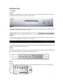
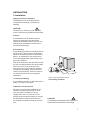
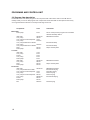
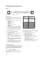
Service manual Dishwashers
Type: DW70
2
Contents
1. Introduction..................................................................................................................4
1.1 Models.................................................................................................................5
2. Technical data..............................................................................................................6
2.1 Technical information.........................................................................................6
3. Installation...................................................................................................................7
4. Component information..............................................................................................9
4.1 Components and measurement values...........................................................9
4.2 Components and function description .........................................................11
. Programs and control unit........................................................................................14
5
5.1 Programs...........................................................................................................14
5.2 Time display......................................................................................................15
5.3 Programs and options.....................................................................................15
5.4 Wiring diagram and timer diagram.................................................................17
5.5 Program flow description................................................................................18
5.6 Settings.............................................................................................................19
5.7 Service menu....................................................................................................25
6. Troubleshooting.........................................................................................................28
6.1 Dishwashing results . ......................................................................................28
6.2 Most common faults.........................................................................................28
6.3 Water level.........................................................................................................29
6.4 Fault indications...............................................................................................30
7. Tools............................................................................................................................32
7.1 Tools...................................................................................................................32
7.2 Special tools.....................................................................................................32
3
INTRODUCTION
1. Introduction
You are holding ASKO’s service manual for the DW70 generation of dishwashers.
The DW70 dishwasher series is available in five different basic models, designated DW70.1,
DW70.3, DW70.4, DW70.5 and DW70.C. On the next page, we present the various panels found
on each type, making it easy to identify the different machines. The different models are named
differently in different markets. The type designation is most important when identifying a particular machine model.
The type plate can be found on the right of the inside of the door.
Type designation
Article number
Year
Week Serial number
The first two digits specify the year of manufacture
while the third and fourth digits specify the week of
manufacture.
It should be easy to service a dishwasher. It is important that you, as a service technician, are afforded
conditions that enable you to work in an efficient and satisfactory way. Our hope is that this service
manual will prove a useful tool in your daily work.
Asko Appliances/After Sales
Box 344
SE-532 24 Skara
Sweden
4
INTRODUCTION
1.1 Models
DW70.1
The DW70.1 is available in two versions, with either one or two options. The machine has four set
programs and the controls are on the front of the panel.
DW70.3
The DW70.3 is available in two versions – with three and five options respectively. The machine has six
set programs and the controls are on the top..
DW70.4
The DW70.4 has a number of different options. The machine has 14 set programs. The controls are on
the top and the display (LCD) is on the top of the panel.
The DW70.3 and DW70.4 models are used in both fully integrated and standard models. Other control
units are only used in standard models.
DW70.5
The DW70.5 is available in two versions – with three and five options respectively. The machine has
five set programs and the controls and display are at the front.
DW70.C
DW70.C
The machine has six set programs and the control and the display are on the front of the panel.
SANI
SANI
Prog
START
END
Start
Stop
SANIWASH
5
Technical data
2. Technical data
2.1 Technical information
Height:
Width:
Depth:
Weight:
Water pressure:
Connection:
Max. rated power:
* According to EN 50242 standard.
** See type plate.
6
823-870 mm (32-1/4” to 35-1/2”) = for 820 mm ma
chines (XL)
863-910 mm (33-3/4” to 36”) = for 860 mm ma
chines (XXL)
596 mm (23-5/8”)
570 mm (22-7/8”)
42 kg / 45 kg with water softener
0.03–0.2 MPa (0.3–2.0 kp/cm2), 18-176 psi
1-phase, 230 V, 50 Hz, 10 A, (120V, 60 Hz, 15 A)**
1700 W, (1300 W)**
INSTALLATION
3. Installation
Suggested machine installations
The dishwasher can be installed built-in,
completely freestanding or partially freestanding.
CAUTION!
Connections to electricity, water and drain
must be performed by qualified professionals.
A. Built-in
The dishwasher can be installed under a
worktop and integrated with the kitchen
cupboards. Read the instructions in the user
manual and the installation instructions for
the actual machine type.
B. Freestanding
A freestanding machine must be fitted with an
anti-tilt device. This comprises two brackets,
which are screwed into place as illustrated in
figure 1. An alternative to the anti-tilt device
is a counterweight that is fixed directly to the
back of the machine.
Push in the machine so that the rear feet slide
into the mounting brackets. Now the machine
will not tip over if a load is placed on the
door when open. If the machine is installed
completely freestanding, side panels and a
worktop should be fitted. These accessories
can be purchased where you bought the
dishwasher.
C. Partially freestanding
If you install the machine so that either side is
visible, you can fit a side panel.
413
45
5-
47
5
600
Figure 1. Anti-tilt brackets used for
freestanding installation
D. Machines with wooden door
Stronger door springs are available for purchase for machines with a fitted wooden
door. Springs are available for various
weights and sizes of wooden door. Door
springs can be purchased where you bought
the dishwasher. Follow the instructions in
the installation manual for fitting the wooden
door.
CAUTION!
A completely freestanding machine must be fitted with an anti-tilt device/counterweight.
7
INSTALLATION
Connection to water supply
The supply pipe must be fitted with a stopcock. The stopcock should be positioned
above the sink unit or at the front of the sink
unit cabinet.
The inlet pipe has a coupling with either a 1/2”
or a 3/4” internal thread, depending on the
country.
Once the machine in installed: Open the stopcock to flush the pipe. Check that all connections are watertight.
Electrical connection
Machines fitted with a cable and plug must be
connected to an earthed socket.
• No part of the drain hose may be more than
950 mm above floor level.
The hose must not be routed directly to the
floor drain or similar. In such cases, the hose can
act as a siphon and empty the machine.
The hose must always discharge at least 350
mm above floor level.
• Attach the hose holder.
(Min. 350 mm and max. 950 mm above floor
level.
Hose holder
Technical data
See the type plate on the right-hand side of
the door.
CAUTION!
The power cable must be disconnected or the
power to the socket turned off when work is
carried out!
Drain connection
• The drain hose connects to a connection
nipple on the sink unit’s water trap (see illustration below). Note that the hose must be attached at the same height as the underneath
of the sink unit otherwise dishwater from the
sink may run down into the dishwasher (see
illustration).
• The drain hose connects to a connection
pipe on the sink unit’s water trap. It must have
an internal diameter of at least 16 mm.
• The drain hose may be extended to a maximum of 3 m. Any connections and connecting pipes must have an internal diameter of at
least 16 mm.
8
Max 950 mm
Min 350 mm
Figure 3.
COMPONENT DESCRIPTION
4.Component description
4.1 Components and measurement values
The specified resistance values apply at room temperature (about 20°C/68°F)
Values within ±10% are considered normal.
Article no.
Position
8073779
8073780,81
8079504
8079505
8078096
8073801,02
8073803,04
8078080
EMC filter
EMC filter
Heater 1600 W 230 V
Heater 1200 W 120 V
Thermistor
Combi disp. 230 V
Combi disp. 120 V
Circ. pump 220/240 V 50
Hz
Circ..pump 220-240 V 50
Hz
Circ..pump 120 V 60 Hz
Circ..pump 120 V 60 Hz
8078080
8078082
8078082
8078087
8078089
8078084
2-3
8078085
2-3
8079502
8079503
8079500
8079501
8078090*
8078090 *
Component
Drain pump 200/240 V
50 Hz, 16 l/min
Drain pump 120V 60 Hz,
16 l/min
Spray arm diverter 230 V
50/60 Hz
Spray arm diverter 120 V
60 Hz
Inlet valve single 200/240
V, 4 l/min
Inlet valve single 120 V,
4 l/min
Inlet valve fuse 220/240
V, 4 l/min
Inlet valve fuse 120 V, 4
l/min
Softener salt water
valve 220/240 V
Softener mixer valve
220/240 V
Primary winding
Measurement
value
680 kohm
1 Mohm
32 ohm
12 ohm
60 kohm
1.6 kohm
0.3 kohm
115 ohm
Auxiliary winding 260 ohm
Primary winding 31,4 ohm
Auxiliary winding 76 ohm
148 ohm
26 ohm
8.5 kohm
2.6 kohm
3.9 kohm
0.95 kohm
2 kohm
0.5 kohm
3 kohm
2.33 kohm
9
COMPONENT INFORMATION
Article no.
Position
Component
Measurement
value
0.65 kohm
Softener salt water
valve 120 V
0.65 kohm
Softener mixer valve
120 V
<10 kohm
8073830
Halogen bulb 5 W/12 V
1.1 kohm
8052778
Vax motor
0,44 kohm
8073850
Fan motor 230 V
0.18 kohm
8073848
Fan motor 120 V
* The number is for a complete water softener; replacement salt and mixer valves are not
available separately.
8078302*
8078302*
4.2 Components and function description
Here we present the functions and specifications of the various electrical components.
Some components are only found in high-end
machines or in particular markets.
Inlet valve
Both single and safety inlet valves are used.
The valve contains a filter to stop particles then
a flow limiter to limit the flow to a maximum of
4 l/min. The valve opens when the water pressure exceeds 0.3 bar and provides full flow at
about 2 bar.
Safety valve
The safety valve has two independent valve
seats, each controlled by a separate electromagnet. The valve seats are connected
in series. This doubles the safety factor. The
electromagnets are also connected in series
(electrically), which means each magnet’s
rated voltage is half the mains voltage (e.g., a
230 V valve = 2 x 115 V coils)
Single valve
The single valve comprises an electromagnet
and a valve seat.
10
Flow meter
The flow meter is fitted in the air gap. The
flow meter is used to control the water intake
so that the right volume is taken in regardless of the water pressure. It is even possible
to program the machine for time-controlled
water intake.
The flow meter comprises an impeller with two
magnets that is driven by the water flow. On the
outside, on the flow meter housing, is a sensor,
a reed switch, which closes each time the magnets pass.The number of pulses from the sensor
is proportional to the volume of the flowing
water. A minimum water flow of 2 litres/minute
is required for the flow meter to operate. If
the necessary level is not reached within one
minute, the program stops.
Output signal: 220 pulses per litre.
Circulation pump
The circulation pump comprises an asynchronous motor, with a pump house capacitor.
COMPONENT INFORMATION
Spray arm diverter
Fan
Note that the spray arms never rotate at the
same time. The spray arms can report the
following status:
• Upper spray arm half or full pressure
• Lower spray arm half or full pressure
Depending on the program, dishwashing
stage and options, the spray arms are set to
various intervals and pressures.
Detergent and rinse aid dispenser
Certain machines are fitted with a spray arm
diverter. The spray arm diverter comprises a
synchronous motor that drives a disc valve
via a gearbox. The disc distributes different
amounts of water from the circulation pump
to the lower and upper spray arms at different
pressures. The motor/gearbox also drives a
cam with four different step times. A switch
detects the cam (step time) and provides
the control unit with feedback on its current
position when setting the desired spray arm
status.
Machines that lack a spray arm diverter utilise
a water distributor instead, which routes the
water to both spray arms. The spray arms
always rotate at the same time.
Heater
The heater is of the flow-through type and is
fitted between the bottom drain and the suction side of the circulation pump. It comprises
a pipe with a heating coil. One side of the
heating coil is fitted with an overheating cutout with a trigger temperature of 98°C and an
automatic reset. The other side is fitted with a
safety fuse that blows at 229°C.
Drain pump
The drain pump comprises a 30 W synchronous motor and a pump component. The
direction of rotation is random, making the
pump partially self-cleaning.
The fan extracts the damp air from the machine during the drying phase of the program.
The fan system has a fan motor that drives
a double-sided fan wheel. Dry air is sucked
in from the opening on one side of the fan
wheel. The hot and damp air from the cleaning compartment is drawn through the other
side of the fan wheel, when a Vax motor
opens a damper. This is done with a slight
delay. Dry and damp air are mixed in a conduit that ends at the top of the door, where
the air is expelled through a nozzle.
The detergent and rinse aid dispenser is
fitted with an electromagnet which upon first
activation dispenses detergent and upon
second activation dispenses rinse aid. The
system is reset when the dishwasher door is
opened.
The dispenser contains a chamber of adjustable volume to set the desired rinse aid dose.
The rinse aid level can be checked using the
optical indicator on the top of the dispenser.
Some models have a sensor, a reed switch,
fitted to the dispenser. This measures the
rinse aid level, which is then indicated on the
panel.
Main power switch
The main power switch has 2 pins and breaks
the phase and the earth. However, power to
the filters, overflow cut-out, drain pump and
inlet valve is not cut when the main power
switch is turned off.
On the DW-70.4 the main power switch is electronic and is integrated with the control unit.
It puts the machine into standby mode when
deactivated.
EMC protection
EMC protection ensures that the machine
does not interfere with nearby electrical
equipment. It also protects the machine from
external interference.
11
COMPONENT INFORMATION
Door switch
A micro switch detects when the door has
been opened. The program is paused and
power to certain components (motor, valves
etc.) is cut. The program continues where it
left off when the door is closed.
Overflow cut-out
The overflow cut-out comprises a float that
triggers a micro switch. This switches off the
inlet valve electrically and starts the drain
pump. The protection remains in place even if
the main power switch is turned off.
Light
The light is a 5 W/12 V halogen bulb powered
by a control unit via a micro switch. The lamp
turns on when the door is opened more than
5°. The lamp is dimmed when lit to reduce
the start current and to extend the life of the
bulb. The control unit features protective
components that limit the current to the light
in case of a short circuit or if a bulb with too
high a power rating is fitted. The bulb can be
replaced from inside the cleaning compartment.
Cables
The machine is fitted with coded connectors
to prevent incorrect wiring. The cables comply with the Rast 2.5 and Rast 5 standards.
Water softener
The water softener softens the intake water
to prevent limescale deposits on dishes and
in the machine. The ion exchange resin is
recharged by opening the salt water valve
(found on the water softener) and releasing
water saturated with salt into the ion exchange chamber during the main wash. The
ion exchange chamber is rinsed clean at the
end of the main wash.
A mixer valve on the water softener controls
the water passing through or bypassing the ion
exchange resin. The higher the water softener
setting, the greater the amount of water pass-
12
ing through the ion exchange resin. When the
mixer valve is open, the water bypasses the ion
exchange resin.
Some models have a sensor, a reed switch,
to detect when the salt needs refilling. Other
models use an optical indicator in the salt filling
hatch.
Air gap
On the side of the machine is an anti-backflow device to prevent dirty water from being
siphoned back into the water system, such
as if a vacuum develops in the water system.
Machines with a water softener also have a
water pocket that is filled with about 2 dl of
water. This water pocket is emptied when the
salt water valve is activated.
Thermistor
The thermistor is at the front edge of the
bottom drain and detects when the selected
water temperature has been reached. If the
thermistor is short-circuited or detaches from
the circuit board, the heater is turned off.
Pressure sensor
The pressure sensor is connected to the
pressure chamber in the bottom drain. It
measures the pressure, which corresponds
to the water level in the machine. If the water level in the machine is too high (for five
consecutive seconds) the drain pump starts
and all other components are switched off.
When the right level is reached, the program
continues where it left off. If the level sensor
generates an output signal of <1 VDC during
the prewash (indicating a blocked filter), an
additional prewash is activated with an SCS
step.
The level sensor also controls the draining time
(can be extended from 25 seconds to a maximum of 3 minutes). Does not apply to DW-70.1
The sensor also checks the need to refill
(such as if a bowl fills with water). Does not
apply to DW-70.1
COMPONENT INFORMATION
Turbidity sensor
Machines with an auto program have a
turbidity sensor that measures how cloudy
the water is. The sensor comprises an LED
and a phototransistor. Between these two is
the dishwater. The less light that reaches the
phototransistor, the cloudier the water. The
sensor is calibrated during the last rinse of
the auto program. At different points during
the auto program the output signal from the
turbidity sensor provides data used to determine how the program will continue (number
of prewashes, temperature, program time,
number of rinses and so on).
If the turbidity sensor fails, the machine assumes the water is “very cloudy”, which results
in a longer program time, prewashes, additional
rinses and so on.
The turbidity meter is located at the front edge
of the bottom drain.
Humidity sensor
The humidity sensor is located in the fan
house. The sensor is of the capacitive type
and measures relative humidity. The humidity sensor measures the ambient humidity
before the drying process begins. The drying
process continues until the humidity sensor
detects a level slightly above ambient humidity (min. time 30 min. and max. time 70 min.).
13
PROGRAMS AND CONTROL UNIT
5. Programs and control unit
5.1 Program
Program
Daily wash
Heavy wash
DW70.3
DW70.5
A
A
A
A
Sani***
Pots & Pans***
Normal wash
A
B
B
Mixed wash**
(only with turbidity sensor)
(only spray arm diverter)
(only duo machines)
A-F
(program alternatives)
Machine type
DW70.1
Auto wash*
*
** ***
DW70.4 DW70.C
X
X
B
C
X
X
X
X
X
X
C
X
Upper half wash**
(EU,AU)
(US)
X
Lower half wash**
Time program
Glass/Delicate wash
Quick wash
C
Rinse & Hold
D
Rinse & Dry
X
D
D
E
D
F
E
X
X
X
X
X
X
X
X
The table below shows which dishwashing processes are activated in each program.
L = Low temperature M = With fan
H = High temperature U = Without fan
Program
1st
prewash
2nd prewash
1st
flush
Temp & drying options
L
H
L
L
X
X
Heavy wash
X
X
Pots & Pans (duo wash
US)
X
X
X**
X
Daily wash
Sani (duo wash EU/AU)
Normal wash
H
X
X
X
X
X
X
X
X
Main
wash
Clean dr. 2nd
pump
Flush
1st
2nd
rinse rinse
Clean
Final
dr. pump rinse
Drying
time L
(min.)
Drying
time H
(min.)
H
L
H
L
L
M
X*
X
X
X
X
X
X
X
X
X
X*
L
H
L
H
X
X
X
X
X
X
X
X
X
X
X
X
X
X
X
X
X
X
X
H
X
L
X
H
H
X
X
L
H
M
X
X
20
U
U
X
X
48
30
48
X
X
48
30
30
30
X
X
48
30
30
30
30
30
X
X
X
X
X
X
X
X
48
30
30
30
Mixed wash
X
X
X
X
X
X
X
X
48
30
30
30
Upper half wash
X
X
X
X
X
X
X
X
48
30
30
30
Lower half wash
X
X
X
X
X
X
X
X
48
30
30
30
Time program 30-60 min.
X
X
X
X
X
X
X
X
X
X
X
X
X
X
X
X
X
X
X
X
X
X
X
X
30
30
0-9
Time program 75-105
min.
X
X
X
X
X
X
X
X
X
X
X
X
X
X
Time program 150-180
min.
X
X
X
X
X
X
X
X
X
X
X
X
X
X
X
X
X
X
X
X
X
X
X
X
X
X
X
X
0
X
X
20
X
X
Time program 120-135
min.
Glass/Delicate wash
Quick wash
Rinse & Dry
Rinse & Hold
14
* only US
** US/AU
X
X
12-25
25-40
49-60
20
20
0
PROGRAMS AND CONTROL UNIT
5.2 Time display
Option
DW70.1: The program progress lamps
around the Start button light up as the program progresses (segment 1 for prewash,
segments 1 and 2 for main wash and so on).
Temperature
DW70.4, DW70.5 When a program is
selected the display indicates how long the
program took the last time it was used. After
the program starts, the time counts down in
one-minute intervals (no recalculation during
the program). The new time is not stored if
any faults occur during the program or if the
program is interrupted.
Super rinse
Program
Auto wash
Option
Temperature
Daily wash
X
Heavy wash
Pots & Pans
Time program
Sani
Normal wash
Mixed wash
Upper half
wash
Lower half
wash
Glass/Delicate
wash
Quick wash
Rinse & Dry
Rinse & Hold
* Humidity sensor
** (C-60°C)
Drying
X*
Delayed
start
X
X
X
X
X
X
X
X
X
X
X
X
X
X
X
X
X
X
X
X
X
X
X
X
X**
X
X
X
X
Time
saver
X
X
X
Delayed start
X
2
2
DW70.5 DW70.4 DW70.C
1
X
X
3
3
X
X
4
4
X
X
1
2
4
Tab***
Set Time.*
Basket loading**
4
** Super
rinse
4
4
X
X
5
5
X
X
X
X
4
(only Time program)
(only spray arm diverter)
(For detergent with water softener)
(option alternatives)
Tab
X
Full
load
X
Upper
load
X
Lower
load
X
Cool touch
X
X
X
X
X
X
X
X
X
X
X
X
X
X
X
X
X
X
X
X
X
X
X
X
X
X
X
X
X
X
X
X
X
X
X
X
X
X
X
X
X
X
X
X
X
X
X
X
X
X
X
X
X
X
X
X
X
X
X
X
X
X
X
Cool touch
*
X
X
X
X
X
DW70.3
Time saver
***
1-5
5.3 Programs with options
DW70.1
1
Drying
Machine type
X
X
X
X
15
COMPONENT
RADIO INTERFERENCE SUPPRESSION FILTER
HEATING ELEMENT 1200W 120V
HEATING ELEMENT 1600W 230V
HEATING ELEMENT 2040W 230V
THERMISTOR
COMBINED DISPENSER 120V
COMBINED DISPENSER 230V
CIRCULATION PUMP 120V 60HZ
CIRCULATION PUMP 230V 50HZ
CIRCULATION PUMP 220V 60HZ
DRAIN PUMP 120V 60HZ
DRAIN PUMP 230V 50HZ
DRAIN PUMP 230V 60HZ
SPRAY ARM DIVIDER 120V 60HZ
SPRAY ARM DIVIDER 230V 50/60HZ
INLET VALVE SINGLE INCL. 120V
INLET VALVE SAFETY INCL. 120V
INLET VALVE SINGLE INCL. 230V
INLET VALVE SAFETY INCL. 230V
SALT VALVE 120V
MIX VALVE 120V
SALT VALVE 230V
MIX VALVE 230V
HALOGEN LAMP 5W 12V
WAX MOTOR
FAN MOTOR 120V
FAN MOTOR 230V
RESISTANCE
1 MOHM
12 OHM
32 OHM
25 OHM
25 KOHM
0.3 KOHM
1,6 KOHM
32 OHM
110 OHM
56 OHM
25 OHM
150 OHM
85 OHM
2.6 KOHM
8,5 KOHM
0.95 KOHM
0.5 KOHM
3,9 KOHM
2 KOHM
0,65 KOHM
0,65 KOHM
3 KOHM
2,3 KOHM
<10 KOHM
1.1 KOHM
0.18 KOHM
0,85 KOHM
RESISTANCES AT ROOM TEMPERATURE (CA. 20°C/68°F)
VALUES WITH +/-10% ARE REGARDED AS NORMAL
MS
CP
HE
DR
N
F
L
HE (PTC)
FN 2
1
3/4
FS
DP
DP
1/C
CD: COMBI DISPENSER
CP: CIRCULATION PUMP
DIV: WATER DIVERTER VALVE
DP: DRAIN PUMP
DR: DOOR
DS: DOOR SWITCH
F: FILTER
FM: FLOW METER
FN 1: FAN DOOR
FN 2: FAN BOTTOM
FS: FLOAT SWITCH
HE: HEATING ELEMENT
HE (PTC): HEATING ELEMENT PTC
HL: HALOGEN LAMP
HS: HUMIDITY SENSOR
IS: ILLUM. SWITCH
IV: INLET VALVE
I2C: I2C
MS: MAIN SWITCH
MV: MIX VALVE
PS: PRESSURE SENSOR
RAS: RINSE AID SENSOR
SL: STATUS LIGHT
SS: SALT SENSOR
SV: SALT VALVE
TH: THERMISTOR
TS: TURBIDITY SENSOR
UART: UART
VAX: VAX ACTUATOR
WIRES IN ALL MACHINES
INTERNAL CONNECTION
WIRES IN SOME MACHINES
HE
RAS
RAS
MS
2
16
DS
10
DS
1/C
HE
2
CD
CD
FN 1
FN
VAX
VAX
CP
4
MV
MV
DIV M
DIV
5
SL
HL
HL
6
I2C
7
UART
8
TS
1/C
2
PS
1 23
IS
FM
TH
TS PS FM TH
HS
80 796 55 - b
CIRCUIT DIAGRAM DW70.1, .3, .4, .5, .C
IV
SV
CP IV SV
3
DW70.1, .C
SS
TH
SS TH
8 9
DW70.3
DW70.4
DW70.5
FORMAT A3
This document must not be copied without
our written pemission, and the contents
thereof must not be imparted to a third party
nor be used for any unauthorized purpose.
Contravention will be prosecuted.
Asko Cylinda AB
SL
HS
PROGRAMS AND CONTROL UNIT
5.4 Wiring diagram
3/4
Program
Quick wash
22'' SCS
T-30º/35º (Eco/normal)
180''
T-30º/35º (Eco/normal)
120" (salt valve active 80")
3''
30''
40''/45'' **
6" or 25'' *
7''
25''
80" cleaning softener ***
40/45''
6"
Upper spray arm
Lower spray arm
Heavy wash
Delicate wash
17
30 50 10 30 15 30 10 20 50 90 10 30
30 50 10 10 45 70 10 20 10 10 10 10
low pressure
High pressure
Time in seconds for water divider action
30 10 50 40 15 10 30 20 50 10 90 70
Both (normal)
30 10 50 40 45 10 70 60 10 10 10 10
Upper basket wash
High pressure
Lower basket wash
low pressure
Mixed wash
Auto, Normal,
Quick, Rinse
programs
Both (normal)
Programs
Mixed wash
Explanation chart for water divider dishwasher DW-70
*** Inlet valve on 8"x 5, off 8" x5. Outlet pump on whole step
** With or without diverther
* If previous program been interrupted = 25"
1st.Rinse
2''
Both (normal)
90''
Upper basket wash
5" paus
Upper basket wash
22'' SCS
Lower basket wash
2''
Lower basket wash
25''
Mixed wash
Components
Inlet valve (mix valve)
Salt valve (Softener)
Drain pump
Circulation pump
Heater
Fan and vax-actuator
Combi dispenser
Timer diagram DW-70 (Quick wash only)
Final rinse
40/45''
Main-wash
T-0º/60º (Eco/normal drying)
Quick wash
Outlet-time can
varies on machines
with pressure sensor
Comments: Water
intake time may
varies with
flowsensor.
Softener
PROGRAMS AND CONTROL UNIT
5.4 Timer diagram
600'' (normal drying)
25''
60" paus
90"/60" (Eco/Normal drying)
60'' (Not Eco drying)
3'' (Not Eco drying)
3'' (Not Eco drying)
Step times
PROGRAMS AND CONTROL UNIT
5.5 Program flow description
Presented below is the Quick program. If the component test in the service menu is not sufficient to
identify a fault you can run this program and compare the results with the flow description below. If they
are in agreement this indicates a correctly functioning control unit.
Component
Main wash
Drain pump
Time
Comments
6 sec.25 sec. if the previous program was cancelled
with the Start/Stop button
Inlet valve
40/45 sec.
With/without diverter
Circ. pump
30 sec.
Circ. pump & Combi dispenser 3 sec.
Circ. pump
120 sec.
Circ. pump & Element T-30º/35º
Eco/Normal temp
Circ. pump
180 sec.
Circ. pump & Element T-30º/60º
Eco/Normal temp
SCS
22 sec.
Super Clean System
Drain pump
25 sec.
1st rinse
Inlet valve
7 sec.
Circ. pump
2 sec.
Pause
5 sec.
Circ. pump
2 sec.
Drain pump
6 sec.
Inlet valve
40/45 sec.
With/without diverter
Circ. pump
90 sec.
SCS
22 sec.
Super Clean System
Drain pump
25 sec.
Final rinse
Inlet valve
40/45 sec.
With/without diverter
Circ. pump & Element T-0/60º
Eco/Normal drying
Circ. pump & Combi dispenser 3 sec.
None Eco drying
Circ. pump
3 sec.
No Eco drying
Circ. pump & Combi dispenser 60 sec.
No Eco drying
Circ. pump
90/60 sec.
Eco/Normal drying
Pause
60 sec.
Drain pump
25 sec.
Fan
600 sec.
Normal drying
18
PROGRAMS AND CONTROL UNIT
5.6 Settings
DW70.1
L2
L1
L2
L3
L12
L6
START
L11
S1
S3
L1
L4
PROGRAM
Variant 1
L10
L6
Variant 2
L8
STOP
S2
S4
L9
L7
START
L11
S1
S2
L5
L12
L4
PROGRAM
L8
STOP
S4
L3
L7
L5
Panel type DW70.1, L = LED, S = Push button
Variant settings
When the power is switched on for the first time
after replacing the control unit, the variant settings
menu is displayed.
L1 flashes: Variant 1 see above, with two options
(temp, dry).
L4 flashes: Variant 2 see above, with one option
(temp).
1. Press the Program button (S1) until either L1
or L4 flashes.
2. Confirm your selection by pressing Start (S2).
(The program automatically returns to the
main menu.)
To return to the variant settings menu:
1. Turn off the main power switch (I/0)
2. Wait at least 5 seconds
3. Press and hold the Program and Start buttons
(S1 & S2)
4. Switch off the main power switch (I/0)
5. Release the Program and Start buttons (S1 &
S2)
6. Press Start (S2) three times within 5 seconds.
Use the Program button (S1) to select the variant
7. Confirm your selection by pressing Start (S2).
The program returns to the main menu.
L10
L9
Setting: Water hardness [°dH] (German water hardness scale)
All LEDs unlit 0-5
(also applies to machines without water softener)
L1 lit
6-8
L1-2 lit
9-14
L1-3 lit
15-19
L1-4 lit
20-29
L1-5 + L11 lit
30-44
L1-6 + L11 + L12 lit 45+
Confirm your selection by pressing Start (S2). The
program returns to the main menu.
Total reset
To reset the machine to its factory settings.
1.
2.
3.
4.
5.
Turn off the main power switch (I/0)
Wait at least 5 seconds.
Press and hold the Program button (S1)
Switch off the main power switch (I/0)
Release the Program button (S1).
L1 and L4 flash during the reset process. The
machine will reset various settings, although not
water hardness, and then automatically return to
the main menu. Detects the presence of a pressure sensor.
Water hardness setting
Activating the settings menu
1. Turn off the main power switch (I/0)
2. Wait at least 5 seconds
3. Press and hold the Start button (S2)
4. Switch off the main power switch (I/0)
5. Release the Start button (S2); L7 starts flashing
6. Use the Program button (S1) to select the desired water hardness
19
PROGRAMS AND CONTROL UNIT
DW70.3
IR
L12
S1
L1
L2
L3
L4
L5
L6
S3
L13
L15
L14
S4
S5
L16
S6
L7
L10
L8
L11
L17
S7
S2
Panel type DW70.3, L = LED, S = Push button,
Variant settings
When the power is switched on for the first time
after replacing the control unit, the variant settings
menu is displayed.
1. Press the Program button (S1) until the desired
variant is selected:
L1 flashes:
Variant1 = Time saver
L2 flashes:
Variant2 = Super rinse option
L3 flashes:
Variant3 = Tab
2. Confirm your selection by pressing Start (S2).
The machine detects the presence of a turbidity sensor, a pressure sensor and a spray arm diverter. The program returns to the main menu.
To return to the variant settings menu:
1. Turn off the main power switch (I/0)
2. Wait at least 5 seconds
3. Press and hold the Program and Start buttons
(S1 and S2)
4. Switch on the main power switch (I/0)
5. Release the Program and Start buttons (S1 and
S2).
Proceed to step 6 within five seconds.
6. Press Start (S2) three times in quick succession.
L1, L2 or L3 flashes according to the previously
selected variant setting
7. Use the Program button (S1) to select a variant
8. Confirm your selection by pressing Start (S2).
The program returns to the main menu.
Water hardness setting
1. Turn off the machine using the main power switch.
2. Press and hold Start/Stop and Drying selector at
the same time as you press the main power switch
once. You have now activated the Softener setting
menu.
START
STOP
+
+
3. Use the Program button PROG to adjust the
water hardness.
4. Press START/STOP to save the setting and exit the
menu.
20
Setting
L1-L6, off
L1 lit
L1-2 lit
L1-3 lit
L1-4 lit
L1-5 lit
L1-6 lit
Water
hardness[°dH]
0-5 (incl. machines
without
extinguished water
softener)
6-8
9-14
15-19
20-29
30-44
45+
Activating of Super rinse (Variant 1 and 3; S7)
Activating the settings menu:
1. Turn off the main power switch (I/0)
2. Wait at least 5 seconds
3. Press and hold the button (S7)
4. Switch on the main power switch (I/0)
5. Release the button (S7)
6. Use the Program button (S1) to select the
desired status
L1 unlit: Super rinse deactivated
L1 lit: Super rinse activated
7. Confirm your selection by pressing Start (S2).
The program returns to the main menu.
PROGRAMS AND CONTROL UNIT
Child safety catch
Activating the settings menu:
1.
2.
3.
4.
5.
6.
Turn off the main power switch (I/0)
Wait at least 5 seconds
Press and hold the temperature and drying option buttons (S4 and S6)
Switch on the main power switch (I/0)
Release the temperature and drying option
buttons (S4 and S6)
Use the Program button (S1) to select the status
L1 unlit: Child safety catch deactivated
L1 lit: Child safety catch activated
Confirm your selection by pressing Start (S2). The
program returns to the main menu.
Temporary deactivation of the Child safety catch is
achieved by pressing the temperature (S4) and drying (S6) option buttons together.
Total reset
To reset the machine to its factory settings.
1.
2.
3.
4.
5.
Turn off the main power switch (I/0)
Wait at least 5 seconds
Press and hold the Program button (S1)
Switch on the main power switch (I/0)
Release the Program button (S1).
The machine will reset various settings, although not
water hardness, variant setting and intake volume.
The machine detects the presence of a turbidity
sensor, a pressure sensor and a spray arm diverter.
The machine then automatically returns to the main
menu.
21
PROGRAMS AND CONTROL UNIT
DW70.4
Panel type DW70.4, L = LED, S = Push button
Special settings
Turn on the main power switch, press the Menu button (S4) a few times until the special settings
are displayed.
The following settings are available:
Language, child safety catch, program end signal,
button tones, temperature (C or F), water hardness setting.
This menu can also be used to view information
about how many cycles the machine has completed and total water consumption.
Water hardness setting:
Setting:Water hardness
[°dH]
The display shows: 0
0-5
(also applies to machines without water softener)
The display shows:
The display shows:
The display shows:
The display shows:
The display shows:
The display shows:
The display shows:
The display shows:
The display shows:
16-8
29-11
312-14
415-19
520-24
625-29
730-39
840-49
950+
Press S3 until the desired setting is shown.
Confirm with S4. The program stores
the settings and returns to the main menu.
22
Store program (in shops, at trade shows
etc.)
Start by pressing and holding S4 with the main
power switch (S5) turned on.
Scrolling text is displayed:
“Turbo Drying ...Super Cleaning System...Auto
Wash...Flexi Racks...Power Zone...8 Steel......Turbo
Drying...”
Quit by pressing the main power switch.
Total reset
After replacing the control unit, the machine will
automatically perform a total reset, which will
detect the presence of the machine’s sensors and
spray arm diverter.
To return to total reset:
1. Turn off the main power switch (I/0)
2. Wait at least 5 seconds
3. Press and hold the Program and Menu buttons
(S1 and S4)
4. Switch on the main power switch (I/0)
5. Release the Program and Menu buttons (S1
and S4).
The machine will reset various settings, although not
water hardness, language, variant and intake volume. The machine detects the presence of a turbidity sensor, a pressure sensor, a humidity sensor and a
spray arm diverter. The machine then automatically
returns to the main menu.
Quick language setting
1.Turn off the main power switch (S5)
2. Wait 5 sec.
3. Press and hold S3
4. Switch on the main power switch (S5)
5. Release S3
6. Use the Program button (S1) to browse to the
desired language
7. Confirm your selection by pressing S2 or S4.
PROGRAMS AND CONTROL UNIT
DW70.5
Panel type DW70.5, L = LED, S = Push button,
D = Display
Variant settings
When the main power switch is switched on for the
first time after replacing the control unit, the variant
settings menu is displayed.
1. Press the Program button (S1) until the
desired variant is selected:
The display shows the number 1 and L1
flashes:
Variant 1 = Time saver
The display shows the number 2 and L2
flashes:
Variant 2 = with Super rinse
The display shows the number 3 and L3
flashes:
Variant 3 = with Tab
The display shows the number 4 and L4 flashes:
Variant 4 = with Time program
2. Confirm your selection by pressing Start
(S2). The machine detects the presence of
a turbidity sensor, a pressure sensor and a
spray arm diverter. The program returns to
the main menu.
To return to the variant settings menu:
1. Turn off the main power switch (I/0)
2. Wait at least 5 seconds
3. Press and hold the Program and Start buttons (S1 and S2)
4. Switch on the main power switch (I/0)
5. Release the Program and Start buttons (S1
and S2). It takes a few seconds for the machine to detect that S1 and S2 are pressed.
Proceed to step 6 within five seconds
6. Press Start (S2) three times in quick succession. L1, L2, L3 or L4 flashes on the
display depending on the previous setting.
7. Use the Program button (S1) to select a variant
8. Confirm with the Start button (S2). The
program automatically returns to the main
menu.
Water hardness setting
Activating the settings menu:
1. Turn off the machine using the main power switch.
2. Press and hold Start/Stop and Drying selector at the
same time as you press the main power switch once. You
have now activated the Softener setting menu.
START
STOP
+
+
3. Use the Program button to adjust the water hardness.
PROG
4. Press START/STOP to save the setting and exit the
menu.
START
STOP
Total reset
Setting
Water hardness [°dH]
Display shows 0
0-5 (incl. machines without
water softener)
Display shows: 1 6-8
Display shows: 2 9-11
Display shows: 3 12-14
Display shows: 4 15-19
Display shows: 5 20-24
Display shows: 6 25-29
Display shows: 7 30-39
Display shows: 8 40-49
Display shows: 9 50+
To reset the machine to its factory settings.
1. Turn off the main power switch (I/0)
2. Wait at least 5 seconds
3. Press and hold the Program button (S1)
4. Switch on the main power switch (I/0)
5. Release the Program button (S1).
The machine will reset various settings, although
not water hardness, language, variant and intake
volume. The machine detects the presence of a
turbidity sensor, a pressure sensor, a humidity
sensor and a spray arm diverter. The machine 23
then automatically returns to the main menu.
DW70.C
Total reset
To reset the machine to its factory settings.
1.
2.
3.
4.
5.
Panel type DW70.3, L = LED, S = Push button,
Water hardness setting
Activate settings menu. :
1. Turn off the machine using the main power
switch.(I/0)
2. Wait for at least 5 seconds.
3. Press and hold the start button (S2)
4. Turn on the machine using the main power
switch(I/0)
5. Realese the button (S2)
6. Use the Program button (S1) to select the
desired status
Setting: Water hardness [°dH]
(German water hardness scale)
Display: 0 0-5 (also applies to machines without
water softener)
Display shows: 1 6-8
Display shows: 2 9-11
Display shows: 3 12-14
Display shows: 4 15-19
Display shows: 5 20-24
Display shows: 6 25-29
Display shows: 7 30-39
Display shows: 8 40-49
Display shows: 9 50+
Confirm your selection by pressing Start (S2). The
program returns to the main menu.
24
Turn off the main power switch (I/0)
Wait at least 5 seconds.
Press and hold the Program button (S1)
Switch off the main power switch (I/0)
Release the Program button (S1).
The machine will reset various settings, although
not water hardness, water inlet volume and feel
presence of turbidity, pressure sensor and
Spray arm diverter and then automatically return
to the main menu. Detects the presence of a pressure sensor.
PROGRAMS AND CONTROL UNIT
5.7. Service menu
Activating the service menu
DW70.1
1.
2.
3.
4.
5.
Turn off the main power switch (I/0)
Wait at least 5 seconds
Press and hold the Program and Start buttons (S1 & S2)
Switch on the main power switch (I/0)
Release the Program and Start buttons (S1
& S2)
L7 flashes
Press S1 to activate the component test. These
are activated in order after each button press:
1. Inlet valve and mixer valve (mixer valve open
1 second then inlet valve open, after next
press of S1 both valves closed 1 second
then only inlet valve open)
2. Salt water valve (salt and mixer valve only in
machines with water softener)
3. Combi dispenser
4. Circulation pump
5. Circ. pump and element (max. 75°C)
6. Fan and Vax motor
7. Drain pump
Adjust water intake (done in service menu)
Press and hold the Program button (S1) for three
seconds. The water intake can now be adjusted
as described below
L1 unlit: Volume-controlled water intake (controlled by flow meter)
L1 lit: Time-controlled water intake
Confirm your selection by pressing Start (S2). The
program returns to the main menu.
DW70.3
1.
2.
3.
Turn off the main power switch (I/0)
Wait at least 5 seconds
Press and hold the Program and Start buttons (S1 and S2)
4. Switch on the main power switch (I/0)
5. Release the Program and Start buttons (S1
and S2)
L10 and L11 flash.
Most recent fault indicated by L1-L6.
Press S1 to activate the component test. These
are activated in order after each button press:
1. Inlet valve and mixer valve (mixer valve
open 1 second then inlet valve open, after
next press of S1 both valves closed 1 second then only inlet valve open). L1 and L2 lit
2. Salt water valve (salt and mixer valve only in
machines with water softener).
L3 lit
3. Combi dispenser. L4 lit
4. Circulation pump. L5 lit
5. Circ. pump and element (max. 75°C). L6 lit
6. Fan and Vax motor. L1 and L2 lit
7. Drain pump. L1, L2 and L3 lit
Adjust water intake (done in service menu)
Press and hold the Program button (S1) for three
seconds. The water intake can now be adjusted as
described below
Press the Program button to step through:
L1-L6 unlit: Normal water intake volume
L1 lit: Water intake volume increases by 5 %
L2 lit: Water intake volume increases by 10 %
L3 lit: Time-controlled water intake
L4 lit: Water intake volume increases by 5% timecontrolled
L5 lit: Water intake volume increases by 10% timecontrolled
L6 lit: Water intake volume increases by 15% timecontrolled
Confirm your selection by pressing Start (S2). The
program returns to the main menu.
25
PROGRAMS AND CONTROL UNIT
DW70.4
1.
2.
3.
4.
5.
Turn off the main power switch (S5)
Wait at least 5 seconds
Press and hold the Program and Start buttons (S1 and S2)
Switch on the main power switch (S5)
Release the Program and Start buttons (S1
& S2)
The service menu has four submenus:
1.
2.
3.
4.
Machine and fault information
Component diagnostics
Adjust water intake
Adjust LCD contrast
Press (S4) to browse between these menus
Press (S3) to enter the selected submenu
and (S4) to return
Machine and fault information displays:
(browse with S3)
1. Date code (year/week) of control unit
2. Software version
3. Most recent fault
4. Second most recent fault (other than most
recent)
5. Third most recent fault (other than two most
recent)
Activating component diagnostics: (browse
with S3)
1. Inlet valve and mixer valve (mixer valve
open 1 second then inlet valve open, after
next press both valves closed 1 second then
only inlet valve open (display shows water
vulume pulses from the flow sensor which is
situated in the lower part of the air break.
2. Salt water valve (salt and mixer valve only in
machines with water softener)
3. Detergent and rinse aid dispenser
4. Circulation pump (display shows turbidity
(dirt sensor) according to chart)
5. Heater and circulation pump (max. 75 °C)
(display shows temperature, see Table)
6. Fan (display shows humidity sensor reading)
7. Drain pump (display shows pressure sensor
reading: according to chart)
Adjust water intake (browse with S3)
Display 0: Normal water intake volume
Display +5 %: Water intake volume increases by
5%
Display +10%: Water intake volume increases by
10%
26
Display +15 %: Water intake volume increases by 15 %
Display Time: Time-controlled water intake
Display +5 %: Water intake volume increases by 5%
Display +10%: Water intake volume increases by 10%
Display +15 %: Water intake volume increases by 15%
Adjust LCD contrast (browse with S3)
LCD contrast = 0, +1, +2, -1.
Press Start (S2) to store the water intake volume and
LCD contrast settings.
The program returns to the main menu.
VDC
Display
0.2
10
0
0.4
0.6
0.8
1.0
1.2
1.4
1.6
1.8
2.0
2.2
2.4
2.6
2.8
3.0
3.2
3.4
3.6
3.8
4.0
4.2
4.4
4.6
4.8
5.0
0
20
31
41
51
61
71
82
92
102
112
122
133
143
153
163
173
184
194
204
214
224
235
245
255
The table shows the voltage and corresponding
display code DW70.4
PROGRAMS AND CONTROL UNIT
DW70.5
1.
2.
3.
Turn off the main power switch (I/0).
Wait at least 5 seconds.
Press and hold the Program and Start buttons
(S1 and S2).
4. Switch on the main power switch (I/0).
5. Release the Program and Start buttons (S1 and
S2) when the LEDs have lit.
The most recent fault is shown in display D2 and
D3. Error messages are erased by a total reset.
Press S1 to activate the component test. These are
activated in order after each button press and are
shown in display D3.
1. Inlet valve and mixer valve (mixer valve open 1
second) then inlet valve open.
2. Only inlet valve open.
3. Salt water valve (salt and mixer valve only in
machines with water softener)
4. Combi dispenser
5. Circulation pump
6. Circ. pump and element (max. 75°C)
7. Fan and Vax motor
8. Drain pump
Adjust water intake (in service menu)
Press the Program button (S1) for 3 seconds to
activate the menu for setting the water intake.
Then use the Program button (S1) to step
through.
The display shows:
P:0 = Normal water intake volume
P:5 = Water intake volume increases by 5%
P:10 = Water intake volume increases by 10%
P:15 = Water intake volume increases by 15%
T:0 = Normal water intake volume
T:5 = Water intake volume increases by 5%
T:10 =Water intake volume increases by 10%
T:15 =Water intake volume increases by 15%
P = water intake controlled by flow meter
T = water intake time-controlled
Confirm selection by pressing Start (S2). The
program returns to the main menu.
DW70.C
1. Turn off the main power switch (I/0).
2. Wait at least 5 seconds.
3. Press and hold the Program and Start buttons
(S1 and S2).
4. Switch on the main power switch (I/0).
5. Release the Program and Start buttons (S1 and
S2) .
The display lights up in five seconds.
Fault indications
Latest occurd fault indicates F1. F2 and so on, on
the display
Component test
Press S1 to activate the component test and step
through the following components:
1. Inlet valve
2. Salt water valve (only in machines with water
softener)
3. Detergent and rinse aid dispenser
4. Cirkulation pump
5. Heater and cirkulation pump
(Max 85°C)
6. Fläkt
7. Avloppspump
Adjust water intake
Hold the program button until ”1” in the display
extinguished. Now, the water intake is adjustable
according to below:
Press the program button and step trough:
The displays shows:
0: Normal water intake volume
1: Water intake volume increases by 5%
2: Water intake volume increases by 10%
3: Water intake volume increases by 15%
4: Time-controlled water intake
5: Time-controlled water intake increases by 5 %
6: Time-controlled water intake increases by 10 %
7: Time-controlled water intake increases by 15%
Confirm selection by pressing Start (S2).
The program returns to the main menu.
27
TROUBLESHOOTING
6. Troubleshooting
6.1 Dishwashing results
Check the following points if the dishes are not
clean (always begin by checking any fault codes
and the most recent fault indication in the
service menu):
• That the customer is using the right dishwashing program.
• If heavily soiled dishes are being loaded, such
as pots or oven dishes, choose a heavier program.
• Check that the customer is using a suitable
dishwashing detergent, preferably one with
proven good results.
• Detergent is a perishable product. Check
that the detergent is not too old and that the
customer is using the right amount. Most
importantly not too much detergent.
• For machines with a water softener, dose as
for soft water.
• Check that the customer is loading the machine correctly.
• Check that no dishes are preventing the
spray arms from rotating and that the holes
are not clogged.
• Check that the machine has the right water
level (see page 29).
• Check that the gauge block on the left side
of the bottom drain by the drain pump is in
place.
• Check that the machine heats to the right
temperature.
Film or marks on dishes after washing
• Is the water softener cover properly
tightened?
• Is the rinse aid dispenser correctly
adjusted?
• Is the water softener correctly adjusted?
• Is there any salt in the salt compartment?
• Is the right type of salt being used?
6.2 Common faults
28
If the dishwasher does not work, you
should first check whether this is due to a
simple fault, something that the customer
can rectify. Use the following questions to
troubleshoot the machine.
The machine will not start
• Has a fuse blown?
• Is the machine powered?
• Is the door properly closed?
• Is the water supply turned on?
If the answer to any of the above questions is
“YES” and the machine seems to lack power,
first check that there is power at the main
power switch and the control unit. Replace
any faulty components.
Water remaining in the machine
• Is the drain hose blocked? Check the connection to the household drain.
• Is the drain hose bent?
• Are the filters blocked?
• Is the drain pump blocked?
• Is the gauge block on the left side of the
bottom drain by the drain pump incorrectly fitted?
If the fault cannot be found with the help of this
chapter, open the service menu and perform an
function test on all components.
TROUBLESHOOTING
6.3 Water level DW70
When servicing a DW70 dishwasher it is
important to check the water level in the
machine.
This is particularly important when programming the time-controlled water intake. Too
low a water level can cause poor dishwashing
results.
Always allow the machine to take in and drain
the water a few times before checking the level.
Overflow level = 4.7 litres
Without spray arm diverter = 3.2
litres
(1.5 mm above the level)
With spray arm diverter = 2.8 litres
(0.5 mm below the level)
Figure: Check the level against the lower spray
arm hub
In the event of too low a water level, the filter
in the inlet valve must always be checked and
rinsed clean of any dirt. The inlet hose with a
¾" connection at both ends has a filter in the
connector outside the machine that must also
be checked and rinsed clean of any dirt.
29
TROUBLESHOOTING
6.4 Fault indication
DW70.1
L2
L1
L3
L12
L2
L7
L4
PROGRAM
L1
START
L11
S1
L10
L5
L6
S3
L9
START
L11
L8
STOP
S2
S4
L10
L5
L6
L7
L4
S1
S2
S4
L12
PROGRAM
L8
STOP
L3
L9
DW70.3
IR
L12
S1
L1
L2
L3
L4
L5
L6
S3
L13
L15
L14
S4
S5
L16
S6
L7
L10
L8
L11
L17
S7
S2
DW70.4
DW70.5
DW70.C
L - LED, S – Push button, F – Fault code or plain text on display, D - Display
The door is open
70.1
70.3
70.4
Lit program progress lamps flash
L10 flashes
“Close door”
70.5
70.C
The display shows
L10 flashes
30
Clean filter: (only DW70.4)
“Clean filter”
Shown automatically after every 300 cycles and is
not a fault indication. This message is a reminder
to the user to check the filters and clean them if
necessary. The message disappears the next
time a button is pressed.
TROUBLESHOOTING
6.4 Fault codes
NB: Some DW70.3 and DW70.4 models
may have a status lamp that always flashes
together with the current fault indicator. If the
customer has activated the sound option an
audible signal is also heard when a fault is
indicated.
Temperature stop fault (DW70.1 no
indication)
70.3 L1 flashes
70.4 “Temp. stop fault”
70.5 Fault code “F1”
70.C Fault code “ F2”
Temperature increase less than 5°C in ten
minutes. Program continues with the process. Only indicated in service menu.
Check: Element, thermistor, water level,
circulation pump, control unit and cables.
Overfilling
70.1 L2 flashes
70.3 L2 flashes
70.4 “Overfilling”
70.5 Fault code “F2”
70.C Fault code “F2”
Too much water in the machine (pressure
sensor) or float activated. If the water has not
been emptied within 60 seconds, the program stops (drain pump activated).
Check: Drain pump (blocked hose), flow
meter, inlet valve, leaks and cables.
Thermistor fault (DW70.1 no indication)
70.3 L3 flashes
70.4 “Thermistor fault”
70.5 Fault code “F3”
70.C Fault code ”F3
Stopped or >80 °C. Program continues with
the process. Only indicated in service menu.
Check: Thermistor and control unit.
< 80 pulses within 60 seconds or correct
number of pulses not achieved within 255
seconds. Program stops.
Check: Water inlet, flow meter, inlet valve
and cables.
Leaking valve
70.1 L5 flashes
70.3 L5 flashes
70.4 “Leaking valve”
70.5 Fault code “F5”
70.C Fault code”F5”
Water intake detected when inlet valve deactivated. Any current program stopped (drain
pump activated).
Check: Leak through inlet valve and flow
meter.
Pressure sensor fault (DW70.1 no
indication)
70.3 L6 flashes
70.4 “Pressure sensor fault”
70.5 Fault code “F6”
70.C Fault code”F6”
Output signal > 4.8 V. The program continues. Only indicated in service menu.
Check: Pressure sensor, control unit and
cables.
Drain fault (DW70.1 no indication)
70.3 L1 and L2 flash
70.4 “Drain error”
70.5 Fault code “F7”
70.C Fault code ”F7”
Water not drained after 120 seconds draining. Program stops.
Check: Drain pump, hoses, drain hose fittings, control unit and cables. Also check
whether filter is blocked.
Water intake fault (DW70.1 no indication)
70.3
70.4
70.5
70.C
L4 flashes
“Water inlet fault”
Fault code “F4”
Fault code ”F4”
31
TOOLS
Turbidity sensor fault (DW70.1 no
indication)
70.3 L1 and L5 flash
70.4 “Turbidity sensor fault”
70.5 Fault code “FA”
70.C Fault code “FA”
Only indicated in service menu. The machine assumes high turbidity in case of “uncertainty” in the
auto program.
Check: Water quality, filters, turbidity sensor
and drain system.
Spray arm diverter fault (DW70.1 no
indication)
70.3 L1 and L6 flash
70.4 “Diverter fault”
70.5 Fault code “FB”
70.C Fault code “FB”
Position switch always closed or open. The
program continues. Only indicated in service
menu.
Check: Spray arm diverter (functioning gearbox, switches and cables).
Humidity sensor fault (only DW70.4)
“Humidity sensor fault” (only in service menu)
Check: Humidity sensor, cables, fan, damper
and Vax motor.
32
7.1 Tools
The following tools are needed to service the
DW70 dishwasher:
Torx
T25
T20
T10
Ring spanner
10 mm
17 mm
Socket screwdriver
10 mm
7.2 Special tools
8801339
Universal tool, dishwasher
7281370
Hose clamp pliers, Oetiker
Article no. 80 836 38 rev. 02
33