1
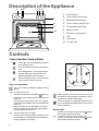
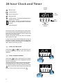
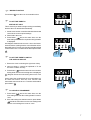
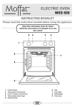
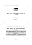
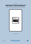
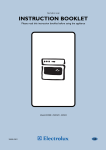
Gas ovens INSTRUCTION BOOKLET Please read this instruction booklet before using the appliance Mod. EOG 621 35674-3501 GB Important Safety Information You MUST read these warnings carefully before installing or using the oven. If you need assistance, contact our Customer Care Department on 08705 950950 Installation This oven must be installed by qualified personnel to the relevant British Standards. Always use oven gloves to remove and replace food in the oven. This oven is heavy. Take care when moving it. Remove all packaging, both inside and outside the oven, before using the oven. Ensure that all control knobs are in the OFF position when not in use. Do not attempt to modify the oven in any way. Do not leave cookware containing foodstuffs, e.g. fat or oil in or on the oven in case it is inadvertently switched ON. The use of a gas cooking appliance results in the production of heat and moisture in the room in which it is installed. Ensure that the kitchen is well ventilated: keep natural ventilation holes open or install a mechanical ventilation device (mechanical extractor hood). When using other electrical appliances, ensure the cable does not come into contact with the hot surfaces of the oven. Prolonged intensive use of the appliance may call for additional ventilation, for example opening a window, or more effective ventilation, for example increasing the level of mechanical ventilation where present. Child Safety This oven is designed to be operated by adults. Do not allow children to play near or with the oven. The oven gets hot when it is in use. Children should be kept away until it has cooled. Maintenance and Cleaning Only clean this oven in accordance with the instructions. The oven should be kept clean at all times. A build-up of fats or other foodstuffs could result in a fire, especially in the grill pan. Always allow the oven to cool down and switch off the electrical supply before carrying out any cleaning or maintenance work. Service During Use This oven is intended for domestic cooking only. It is not designed for commercial or industrial purposes. Do not block any of the oven vents. Never line any part of the oven with aluminium foil. Do not allow heatproof cooking material, e.g. roasting bags, to come into contact with oven elements. Never place plastic or any other material which may melt in or on the oven. Do not place sealed cans or aerosols inside the oven. They may explode if they are heated. Do not hang towels, dishcloths or clothes from the oven or its handle. Do not use this oven if it is in contact with water and never operate it with wet hands. Take great care when heating fats and oils as they will ignite if they become too hot. 2 This oven should only be repaired or serviced by an authorised Service Engineer and only genuine approved spare parts should be used. Environmental Information After installation, please dispose of the packaging with due regard to safety and the environment. When disposing of an old appliance, make it unusable, by cutting off the cable. Remove any door catches, to prevent small children being trapped inside. Keep this instruction book for future reference and ensure it is passed on to any new owner. Contents For the User For the Installer Important Safety Information 2 Instructions for the Installer 14 Guide to Use the instructions 3 Important Safety Requirements 14 Description of the Appliance 4 Building in 15 Controls 4 Electrical Connection 16 Before the First Use 5 Gas connection 17 24 hour Clock and Timer 6 Conversion from Natural to LPG Gas 18 Using the Oven 8 Hints and Tips 8 Grilling with the turnspit 8 Gas Oven Cooking Charts 9 Cleaning the Oven 10 Something Not Working 11 Service and Spare Parts 12 Customer Care 12 Guarantee Conditions 13 Guide to Use the instructions The following symbols will be found in the text to guide you throughout the Instructions: Safety Instructions F Step by step instructions for an operation Hints and Tips Environmental information This appliance complies with the following E.E.C. Directives: * 73/23 - 90/683 (Low Voltage Directive); * 93/68 (General Directives); * 89/336 (Electromagnetical Compatibility Directive) . and subsequent modifications 3 Description of the Appliance 7 65 4 3 2 1 8 9 10 1. Control panel 2. Thermostat control knob 3. Gas stop Control Light 4. Oven function control knob 5. Thermostat control light 6. Mains on light 7. Electronic programmer 8. Grill 9. Oven lamp 10. Turnspit hole Controls Oven Function Control Knob Oven Light - The oven light will be on without any cooking function. Grill - The heat comes from the top element only Grill and Rotisserie - The turnspit can be used for either spit roasting meat or for kebabs and smaller pieces of meat. Bottom heating element - The heat comes from the bottom of the oven only Gas oven operation FO 2478 The oven cannot be switched on with the use of flames. F - - F - 4 To switch on the oven: Turn the oven function control knob to (the oven lamp and the yellow light on the control panel will come on) Turn the thermostat control knob to the required temperature (the red light on the control panel will come on). After 5 seconds, the oven will ignite. If the oven does not switch on, the gas stop control light on the control panel will come on. To try to switch the oven again: turn the oven function and the thermostat control knobs to l (zero) and wait some seconds before trying to ignite the oven again. When using the oven for the first time, it may be necessary to try the ignition several times: this is due to the air inside the gas pipes. If there is a black out during the operation of the oven, this will automatically switch on as soon as power is restored. Electric grill - Turn the oven function control knob to and the thermostat control knob to MAX; To use the rotisserie and the electric grill: - Turn the oven function control knob to and the thermostat control knob to 200°. F Thermostat Control Knob 100 150 The thermostat control light will come on when the thermostat control knob is turned. The light will remain on until the correct temperature is reached. It will then cycle on and off to show the temperature is being maintained. 0 Thermostat Control Light 20 The oven function control light will come on when the oven function control knob is set. MAX Mains on Light 50 Turn the thermostat control knob clockwise to select temperatures between 50°C and 250°C (MAX). FO 2482 Gas stop Control Light The gas stop control light will come on when the oven burner switches off. To switch on, turn the control knob to zero and wait some seconds, then ignite again. Cooling fan The cooling fan operates during cooking. Air is expelled through vents between the oven door and the control panel, as shown in the diagram. The cooling fan may run on after the oven is switched off to keep the controls cool. This is quite normal. The Safety Thermostat (Electric Grill) This oven is provided with a safety thermostat. In case of malfunctioning of the main thermostat, and consequent over-heating, the safety device will stop the power supply to the appliance. If this happens, call your local Service Force Centre. Under no circumstances should you attempt to repair the appliance yourself. Before the First Use Remove all packaging, both inside and outside the oven, before using the appliance. Before first use, the oven should be heated without food. During this time, an unpleasant odour may be emitted. This is quite normal. F 1. Switch the gas oven function control knob to and the thermostat control knob to maximum position. 2. Open a window for ventilation. 3. Allow the oven to run empty for approximately 45 minutes. 5 24 hour Clock and Timer Cookpot symbol Minute minder Cooking duration End of cooking time A U T O Manual function Cookpot symbol - This will be displayed when a program is in operation. Auto symbol - This will be displayed when the oven has been programmed for automatic operation. A U T O - + Time setting knob - + Programming controls The electronic timer can indicate the time of day, operate as a minute minder and automatically operate the oven. Before the oven can be operated, the time of day must be set on the electronic timer. Please note that this is a 24 hour clock. For example, 2pm is shown as 14:00. In case of loss of power, all the settings (time of day, set program or program in operation), will be cancelled. When the power is restored, the numbers on the display will flash, and the timer has to be reset. F TO SET THE TIME OF DAY Press buttons and , and at the same time turn the time setting knob until the correct time of day is displayed. - + F TO SET THE MINUTE MINDER Press button and at the same time turn the setting time knob until the duration time is displayed (maximum 23 hours, 59 minutes). Our diagram shows the timer set for 35 minutes. After a few seconds the time of day will show in the display. To check the number of minutes remaining, press the button. At the end of the timed period an alarm will sound. To switch off the alarm press button . - + 6 Auto symbol Time setting F MANUAL FUNCTION Press button to set the oven for manual function. F TO SET THE TIMER TO - + SWITCH OFF ONLY This is useful if you want to begin cooking immediately but have the oven switch off automatically. 1. Set the oven function control knob and the thermostat control knob on the required settings. 2. Place food in the oven. 3. Press button and, at the same time, turn the time setting knob until the required cooking duration is displayed. Our diagram shows the timer set for 1 hour 10 minutes. At the end of the cooking time the oven will switch off, an alarm will sound. Turn the oven function and thermostat control knob to zero. To switch off the alarm press button A U T O - + . F TO SET THE TIMER TO SWITCH THE OVEN ON AND OFF 1. Ensure the clock is showing the right time of day. 2. Carry out steps 1, 2 and 3 as explained in "To set the timer to switch off only". 3. Press button and at the same time turn the time setting knob until the end cooking time is displayed. Our diagram shows the end cooking time set for 7:35 pm. At the end of the cooking time the oven will switch off, an alarm will sound. Turn the oven function and thermostat control knob to zero. To switch off the alarm press button A U T O - + . F TO CANCEL A PROGRAMME 1. Press button and, at the same time, turn the time setting knob until the cooking duration is set on "zero". 2. If the end cooking time has been set too, press button and at the same time turn the time setting knob until the end cooking time is set on "zero". 7 Using the Oven 4 Always cook with the oven door closed. 3 Stand clear when opening the drop down oven door. Do not allow it to fall open - support the door using the door handle, until it is fully open. 2 The oven has four shelf levels, and is supplied with two shelves. The shelf positions are counted from the bottom of the oven as shown in the diagram. 1 FO 0336 It is important that these shelves are correctly positioned as shown in the diagram. Do not place cookware directly on the oven base. ANTI-TIP SHELF Hints and Tips Condensation and steam When food is heated it produces steam in the same way as a boiling kettle. The oven vents allow some of this steam to escape. However, always stand back from the oven when opening the oven door to allow any build up of steam or heat to release. If the steam comes into contact with a cool surface on the outside of the oven, e.g. a trim, it will condense and produce water droplets. This is quite normal and is not a fault with the oven. To prevent discouloration, regularly wipe away condensation and also soilage from surfaces. Cookware Use any oven proof cookware which will withstand temperatures of 250°C. Baking trays, oven dishes, etc. should not be placed on the oven base. Do not use baking trays larger than 30 cm x 35 cm (12 in x 14 in) as they will restrict the circulation of heat and may affect performance. The effects of dishes on cooking results Dishes and tins vary in their thickness, conductivity, colour, etc. which affects the way they transmit heat to the food inside them. A Aluminium, earthenware, oven glassware and bright shiny utensils reduce cooking and base browning. B Enamelled cast iron, anodized aluminium, aluminium with non-stick interior and coloured exterior and dark, heavy utensils increase cooking and base browning. Grilling with the turnspit 1. Place the proper spit support in the oven. 2. Place the food in the spit and fix the forks by means of the screws. 3. Insert the point of the spit in the motor drive hole, which can be found in the back panel of the oven. 4. Place the outside edge of the spit on the spit support and unscrew the handle. 5. Insert the dripping pan in the lowest level, after pouring a little water in it. 6. Turn the thermostat control knob to 200. Maximum cooking time: 60 minutes. 8 FO 0537 Gas Oven Cooking Charts TEMPERATURE °C SHELF POSITION COOKING TIME Milk puddings Baked sponge pudding 170 210 2 2 1½ - 2 hours 45-60 minutes Baked custard 190 2 50-60 minutes Rich Fruit Cake Christmas Cake Victoria Sandwich 170 170 210 3 3 2 or 3 2¼ hours 3½ - 4½ hours 20-30 minutes Madeira Cake 210 2 or 3 1 hour Small Cakes 225 3 15-25 minutes Plate tart 240 2 50 minutes FOOD PUDDINGS This chart is intended as a guide only. It may be necessary to increase or decrease the temperature to suit your individual requirements. Only experience will enable you to determine the correct setting for your personal requirements. CAKES Fruit pie 240 2 50 minutes Mince pies 225 2 or 3 15-25 mins Profiteroles 210 2 25 minutes Bread 1lb Loaves MAX 2 or 3 30-40 minutes Bread 2lb Loaves MAX 2 or 3 30-40 minutes Rolls and Buns MAX 2 or 3 10-20 minutes 225 2 or 3 20-30 minutes per lb YEAST MIXTURES ROASTING MEAT Beef Lamb 225 2 or 3 25-30 minutes per lb Pork and veal 225 2 or 3 30-35 minutes per lb Chicken 225 2 or 3 20 minutes per lb Turkey 210 2 or 3 15-25 minutes per lb Duck and duckling 225 2 or 3 25 minutes per lb Stuffed poultry 225 2 or 3 25 minutes per lb Grilling Quantity FOOD 4 3 2 1 Number Shelf Gramms of pieces position Steaks Sausages Chicken joints Kebabs Tomatoes Fish filets Toasts Bread 4 8 6 4 8 4 4 4 800 500 800 700 500 400 — — Minutes Grilling 4 4 3 4 4 4 4 4 temperature °C upper side lower side MAX MAX MAX MAX MAX MAX MAX MAX 10 10 30 12 12 8 8 2~3 8 6 20 10 — 6 — 1 Cooking with the turnspit FOOD Chicken Roasts Gramms 1000 800 Shelf position 3 3 Temp. °C minutes 200 200 50/60 50/60 9 Cleaning the Oven The oven should be kept clean at all times. A build-up of fats or other foodstuffs could result in a fire, especially in the grill pan. Cleaning materials Before using any cleaning materials on your oven, check that they are suitable and that their use is recommended by the manufacturer. Cleaners that contain bleach should NOT be used as they may dull the surface finishes. Harsh abrasives should also be avoided. Oven Shelves To clean the oven shelves, soak in warm soapy water and remove stubborn marks with a well wetted soap impregnated pad. Rinse well and dry with a soft cloth. Oven lamp replacement Disconnect the appliance. External cleaning Regularly wipe over the control panel, oven door and door seal using a soft cloth well wrung out in warm water to which a little washing up liquid has been added. To prevent damaging or weakening the door glass panels avoid the use of the following: Unscrew the lamp and replace it with another suitable for higher temperatures (300°C) having the following characteristics: Voltage: 230-240V (50Hz) Power: 25W Connection: E14 Household detergent and bleaches Impregnated pads unsuitable for non-stick saucepans Brillo/Ajax pads or steel wool pads Chemical oven pads or aerosols Rust removers Bath/Sink stain removers Clean the outer and inner door glass using warm soapy water. Should the inner door glass become heavily soiled it is recommended that a cleaning product such as Hob Brite, or Bar Keepers Friend is used. DO NOT clean the oven door while the glass panels are warm. If this precaution is not observed the glass panel may shatter. If the door glass panel becomes chipped or has deep scratches, the glass will be weakened and must be replaced to prevent the possibility of the panel shattering. Contact your local Service Centre who will be pleased to advise further. Oven Cavity The enamelled oven cavity is best cleaned whilst the oven is still warm. Wipe the oven over with a soft cloth soaked in warm soapy water after each use. From time to time it will be necessary to do a more thorough cleaning, using a proprietary oven cleaner. 10 FO 0287 Something Not Working If the appliance is not working correctly, please carry out the following checks, before contacting your local Service Force Centre. IMPORTANT: If you call out an engineer to a fault listed below, or to repair a fault caused by incorrect use or installation, a charge will be made even if the appliance is under guarantee. SYMPTOM n The oven or grill will not light SOLUTION u Check that the oven is switched on at the wall u Check that the power supply has not been interrupted before the cooling fan has had time to cool the oven down u Check that there is not a problem with your gas supply n Food is cooking too quickly or too slowly u Check that you are using the recommended gas marks and shelf positions n The oven is not cooking evenly u Check that the oven is installed properly and is level. u Check that you are using the recommended gas marks and shelf positions n The oven light does not work n Steam and condensation settle on the food and the oven cavity. u Check the light bulb, and replace it if necessary (see "Oven lamp replacement") u Refer to the contents of this booklet, especially to the chapter Using the Oven. u Leave dishes inside the oven no longer than 15-20 minutes after the cooking is completed. If after these checks, the appliance still does not work, contact your local Service Force Centre. When you contact the Service Force Centre, they will need the following information: 1. Your name, address and post code. 2. Your telephone number 3. Clear and concise details of the fault 4. The model and the serial number (see rating label) 5. Date of purchase 11 Service and Spare Parts If you require spare parts or an engineer contact your local Service Force Centre by telephoning: 08705 929 929 Your call will be routed to the Service Centre covering your post code area. For the address of your local Service Force Centre and further information about Service Force, please visit the website at www.serviceforce.co.uk Customer Care For general enquiries concerning your appliance and for further information on Electrolux products, contact our Customer Care Department by letter or telephone as follows: Customer Care Department Electrolux 55-77 High Street Slough - Berkshire SL1 1DZ Tel : 08705 950 950* * calls to this number may be recorded for training purposes 12 Guarantee Conditions Electrolux Standard Guarantee Conditions We, Electrolux, undertake that if, within 12 months of the date of the purchase, this Electrolux appliance or any part thereof is proved to be defective by any reason only of faulty workmanship or materials, we will, at our option, repair or replace the same FREE OF ANY CHARGE for labour, materials or carriage on condition that: * The appliance has been correctly installed and used only on the gas and electricity supply stated on the rating plate. * The appliance has been used for normal domestic purposes only, and in accordance with the manufacturer's instructions. * The appliance has not been serviced, maintained, repaired, taken apart or tampered with by any person not authorised by us. * All service work under this guarantee must be undertaken by an Electrolux Service Force Centre. * Any appliance or defective part replaced shall become the Company's property. * This guarantee is in addition to your statutory and other legal rights. Home visits are made between 8.30am and 5.30pm Monday to Friday. Visits may be available outside these hours, in which case a premium will be charged. Exclusions This guarantee does not cover: * Damage or calls resulting from transportation, improper use or neglect, the replacement of any light bulbs or removable parts of glass or plastic. * Costs incurred for calls to put right an appliance which is improperly installed or calls to appliance outside the United Kingdom. * Appliances found to be in use within a commercial or similar environment, plus those which are the subject to rental agreements. * Products of Electrolux manufacture which are not marketed by Electrolux. European Guarantee If you should move to another country within Europe then your guarantee moves with you to your new home subject to the following qualifications: * The guarantee starts from the date you first purchased your product. * The guarantee is for the same period and to the same extent for labour and parts as exist in the new contry of use for this brand or range of products. * This guarantee relates to you and cannot be transferred to another user. * Your new home is within the European Community (EC) or European Free Trade Area. * The product is installed and used in accordance with our instructions and is only used domestically, i.e. a normal household The electrical supply complies with the specification given in the rating label. * The product is installed taking into account regulations in your new country. Before you move, please contact your nearest Customer Care centre, listed below, to give them details of your new home. They will then ensure that the local Service Organisation is aware of your move and able to look after you and your appliances. France Senlis +33 (0)3 44 62 22 22 Germany Nürnberg +49 (0)911 323 2600 Italy Pordenone +39 (0)1678 47053 Sweden Stockholm +46 (0)20 78 77 50 UK Slough +44 (0)1753 219 898 13 Instructions for the Installer Technical Data Model Number: Oven EOG 621 APPLIANCE GAS SUPPLY: Natural Gas G20 20mbar APPLIANCE CATEGORY:II 2H3+ Cabinet Dimensions Minimum aperture height Minimum aperture depth Minimum aperture width Grill Element Oven burner Oven light Cooling fan Turnspit motor Total rating Supply voltage (50 Hz) 1,830 W 2,700 W (Natural gas) 2,500 W (LPG) 25 W 25 W 4W 1,880 W 230-240 V 580 mm 550 mm 560 mm Important Safety Requirements This appliance must be installed in accordance with the Gas Safety (Installation and Use) Regulations (current addition) and the I.E.E. Wiring Regulations. Detailed recommendations are contained in the following British Standard Codes of Practice - B.S. 6172, B.S. 5440: Part 2 and B.S. 6891: Current Editions. Provision for Ventilation This appliance is not connected to a combustion products evacuation device. It shall be installed and connected in accordance with the current installation regulations. Particular attention shall be given to the relevant requirements regarding ventilation. The room containing the appliance should have an air supply in accordance with BS. 5440: Part 2 Current Edition. All rooms require an openable window or equivalent and some rooms will require a permanent vent as well. For room volumes up to 5m3 an air vent 100cm2 is required; for room volumes between 5m3 and 10m3, an air vent with a minimum area of 50cm2 is required. If the room has a door which opens directly to the outside, no air vent is required. For room volumes that exceed 11m3 no air vent is required. If there are other fuel burning appliances in the same room, B.S. 5440: Part. 2: Current Editions should be consulted to determine the requisite air vent requirements. Prolonged intensive use of the appliance may call for additional ventilation, for example opening a window, or more effective ventilation, for example increasing the level of mechanical ventilation where present. 14 Building in Location of appliance The appliance may be located in a kitchen, a kitchen/ diner or bedsitting room but not in a bathroom, shower room or bedroom. It is essential that there is a minimum clearance of 3mm between the top surface of the appliance and the inside top of the cabinet. The unit must be fitted into a cabinet conforming to Fig.2. This oven unit may be used in a Built-in or a Built-under situation (see relevant diagrams). If the appliance is to be built-under a hob, it is recommended thet the hob be installed before the oven unit. Fig.1 FO 0374 550 BUILDING IN The surround or cabinet into which the oven will be built must comply with these specifications: l the dimensions must be as shown in the relevant diagrams; l the materials must withstand a temperature increase of at least 60°C above the ambient temperature; l proper arrangements must be made of a continuous supply of air to the oven to prevent the oven overheating. 580 Please ensure that when the oven is installed it is easily accessible for the engineer in the event of a breakdown. 44 i 0 m n 110 560 -57 0 Fig.2 FO 0290 min 550 56 0÷ 57 0 591 min. 4 Dimensions of the oven and recess required are given in the relevant diagrams (in millimetres). 110 Fig.3 FO 2128 0 56 0÷ 57 591 min. 4 min 550 140 Fig.4 240 110 FO 2129 15 Securing the oven to the cabinet 1. Fit the oven into the cabinet recess, 2. Open the oven door 3. Secure the oven to the kitchen cabinet with four wood screws, which fit the holes provided in the oven frame. Fig.5 FO 0039 Electrical Connection The oven is designed to be connected to 230-240V (50Hz) electricity supply. The oven has an easily accessible terminal block which is marked as follows: Letter L Letter N or E - Live terminal Neutral terminal - Earth terminal The switch must not break the yellow and green earth cable at any point. THIS OVEN MUST BE EARTHED The cable used to connect the oven to the electrical supply must comply to the specifications given below. For Uk use only Connection via Min. size Cable/flex Cable / flex type Fuse 13 A socket outlet 13 A spur box 2.5 mm2 3 core butyl insulated 13 A min. Cooker Control Circuit 2.5 mm2 PVC/PVC twin and earth 13 A For Europe use only Min. size Cable/flex Cable / flex type Fuse 1.5 mm2 H05 RR-F 13 A 16 It is necessary that you install a double pole switch between the oven and the electricity supply (mains), with a minimum gap of 3mm between the switch contacts and of a type suitable for the required load in compliance with the current rules. Important After installation and connecting, the cable must be placed so that it cannot at any point reach a temperature of more than 60°C above the ambient temperature. Before the oven is connected, check that the main fuse and the domestic installation can support the load; and that the power supply is properly earthed. The manufacturer disclaims any responsibility should these safety measures not be carried out. Gas connection Fitting the appliance and cabinet The gas supply connection ramp is positioned in the front upper side of the oven, behind the control panel. To carry out the gas connection, partially insert the oven in the recess (about 30 cm.) and operate on the connection ramp from the top. The gas connection can be carried out in both the following systems: 1) Fig. 6 flexible metallic pipes (with maximum length up to 2 metres only) screw the feed pipe to the 1/2 connection ramp, inserting the gasket provided between the pipe and the ramp; 2) Fig. 7 rigid metallic pipe (soft copper - minimum diameter: 8 mm) insert the copper pipe into the connection ramp after fitting the correct nut and olive onto the copper pipe using a male / female adapter (not supplied). To carry out the connection: - tighten (fig.8) the nuts by means of a 22 mm. spanner, in order to keep the ramp in position and not to cause any distortion to the gas supply circuit. - completely insert the oven in the recess and secure it as indicated in the relevant paragraph. flexible metallic pipe gasket Fig.6 FO 0671 nut rigid metallic pipe olive male / female adapter Check the gas supply ramp and the gas connection pipe are not squeezed while the oven is positioned into the recess. The use of rubber flexible hoses is not permitted. Fig.7 WARNINGS • • Using a gas cooking appliance will produce heat and moisture in the room which it has been installed in. Ensure a continuous air supply, keeping the air vents in good conditions or installing a cooker hood with discharge tube. In case of intensive or long time use of the appliance, make the ventilation more efficient, by opening a window or increasing the electric exhaust fan power. Check the perfect sealing of the connection using leak detection fluid. FO 0672 gas supply ramp Fig.8 FO 0673 nut 17 Conversion from Natural to LPG Gas IMPORTANT The replacement/conversion of the gas hob should only be undertaken by a CORGI registered engineer. It is important to note that this model is designed for use with natural gas but can be converted for use with butane or propane gas providing the correct injectors are fitted. The gas rate is adjusted to suit. The oven burner does not need any primary air regulation. b a Replacement of gas oven burner nozzle To replace the gas oven nozzle, follow this procedure: a) remove the bottom of the oven; b) undo screw a and b and take the oven burner out; c) with a socket spanner 7 unscrew and remove the nozzle, situated in the bottom of the oven, and replace it with the correct one (see Table on this page); d) reassemble the burner following the same procedure backwards. TYPE OF GAS NOZZLES 1/100 MM NOMINAL KW Natural gas 18 POWER IN POWER Fig. 9 REDUCED BY-PASS GAS NOMINAL MIN MAX POWER 1/100 MM PRESSURE PRESSURE PRESSURE mbar mbar 3 m /h g/h (KW) (mbar) (G20) 114 2,7 257 - 1,1 Reg. 20 17 25 Butane (G30) 78 2,5 - 182 1,1 52 30 20 35 Propane (G31) 78 2,5 - 179 1,1 52 37 25 45 CUSTOMER CARE Electrolux 55-77 High Street Slough Berkshire, SL1 1DZ Tel: 08705-950950 © Electrolux plc 2002 From the Electrolux Group. The worlds No.1 choice. Grafiche MDM - Forlì The Electrolux Group is the worlds largest producer of powered appliances for kitchen, cleaning and outdoor use. More than 55 million Electrolux Group products (such as refrigerators, cookers, washing machines, vacuum cleaners, chain saws and lawn mowers) are sold each year to a value of approx. USD 14 billion in more than 150 countries around the world. 09/02