1
VideoLabs Ceiling DocCamTM
®
Installation Instructions & Operator’s Guide
1
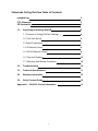
VideoLabs Ceiling DocCam Table of Contents
Intended Use
3
FCC Statement
CE Declaration
3
3
1.0
Unpacking and Getting Started
4
1.1 Contents of Ceiling DocCam Package
4
1.2 First-Time Set Up
4
1.3 Cable Connections
7
1.4 IR Remote Control
9
1.5 RS-232 Remote Control
9
1.6 Care and Cleaning
10
1.7 Operating And Storage Conditions
10
2.0
Troubleshooting
10
3.0
Technical Specifications
11
4.0
Warranty Information
12
5.0
Quick Connect Guide
14
Appendix 1 – RS-232C Control Information
2
15
INTENDED USE
Before operating the Ceiling DocCam, please read the entire manual thoroughly. The
VideoLabs Ceiling DocCam was designed, built and tested for use indoors, and with the
provided power supply. The use of a power supply other than the one provided or
outdoor operation has not been tested and could damage the camera or peripheral
equipment and/or create a potentially unsafe operating condition.
IMPORTANT SAFEGUARDS
1. Read and understand all instructions before using.
2. Do not operate the appliance if the power cord is damaged or if the appliance
has been dropped or damaged. A qualified service technician must examine the
appliance before operating.
3. Position the cord so that it will not be tripped over, pulled, or in contact with hot
surfaces.
4. Always unplug the appliance from the electrical outlet before cleaning or
servicing.
5. To reduce the risk of electric shock, do not immerse in water or other liquids.
Use only the power supply provided with the Ceiling DocCam.
Use of any unauthorized power supply will void any and all warranties.
SAVE THESE INSTRUCTIONS
The information contained in this manual will help you install and operate your
VideoLabs Ceiling DocCam.
FCC STATEMENT - CLASS B:
This equipment has been tested and found to comply with the limits for a class B digital
device, pursuant to Part 15 of the FCC rules. These limits are designed to provide
reasonable protection against harmful interference in a residential installation. This
equipment generates, uses and can radiate radio frequency energy, and if not installed
and used in accordance with the instruction manual may cause interference to radio
communications. However, there is no guarantee that interference will not occur in a
particular installation. If this equipment does cause interference to radio or television
reception, the user is encouraged to correct the interference by one or more of the
following measures:
1. Reorient or relocate the receiving antenna.
2. Increase the separation between equipment and receiver.
3. Connect equipment into an outlet on a circuit different from that of the receiver.
4. Consult the dealer or an experienced radio TV technician for help.
CE DECLARATION
In accordance with ISO / IEC Guide 22 and BS 7514
This product complies with the requirements of the EMC directive 89/336/EEC.
Electromagnetic Emissions: EN 55022: 1995 Class B
Electromagnetic Immunity: EN 50082-1: 1992
3
1)
Unpacking and Getting Started
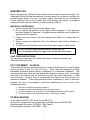
1.1
Contents of Ceiling DocCam Package
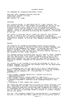
The following items are included with the Ceiling DocCam
(see Figure 1):
1.
2.
3.
4.
5.
6.
7.
8.
9.
Camera Module in UL Rated Plenum Enclosure
White Ceiling Trim Ring
Two Ceiling Tile Support Rails with Aluminum Positioning Clips
Wall Plate for Composite Video, S-Video and Power Connections
RCA Jack to BNC Plug Adapter
IR Remote Control with 2 - AAA Batteries
50 Foot Plenum Rated Category 5 Cable (RJ-45 to RJ-45)
25 Foot S-Video (S-VHS) Cable
12 Volt DC Power Supply
Figure 1
If any of the items are missing, please contact VideoLabs at 1-800-467-7157 or 763-542-0061.
1.2
First-Time Set Up of the Ceiling DocCam
The Ceiling DocCam is an integrated document/object camera designed for use
within a suspended ceiling. Recommended ceiling heights are between 8 to 11
feet. To locate the Ceiling DocCam above the surface of the table, follow these
steps:
1. Start with a string or plumb bob and attach it to the ceiling tile with a thumb
tack.
2. Position the string directly over ample table space or work surface and allow
for easy access for document and object positioning.
4
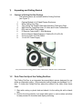
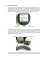
3. Cut a 3-1/2” diameter round hole into the front side of the ceiling tile centered
on the string. It is strongly recommended to score the front of the tile with a
sharp utility knife prior to cutting the tile. The camera module bezel (front
ring) will fit into the 3-1/2” opening from the rear of the tile (see Figure 2).
Figure 2: Side View – Camera Module Enclosure
Bezel (front ring)
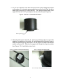
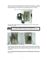
4. Attach the tile support rails with the aluminum positioning clips to support the
weight of the camera on the ceiling tile and between the ceiling grid runners.
Attach the positioning clips as shown to the tile support rail and to the camera
module enclosure fin. Slide the tile support rail through the clip into position
(see Figures 3 & 4) and tighten down firmly.
Figure 3: Enclosure with Tile Support Rails Attached
Figure 4: Positioning Clip Attached to Rails
Note: Attach Clip to Rail and Enclosure Fin as Shown
5
5. The tile support rails distribute the weight of the camera into the grid and
prevent tile warping. The camera module enclosure and the tile support rails
allow for exceptional positioning freedom when used with 2’x2’ and 2’x4’
ceiling tiles (Figure 5).
Figure 5: Enclosure and Tile Support Braces Positioned on 2’x2’ Ceiling Tile
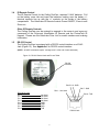
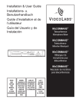
6. After the camera module enclosure is positioned above the ceiling, attach the
white trim ring to the camera module bezel from the front of the tile and
tighten gently. This will pull the bezel and camera module together and firmly
hold the camera in position against the ceiling tile. Rotate the camera
enclosure module with the positioning indicator pointing toward the monitor or
display device. This orientation is standard document camera orientation
(see Figures 6 & 7).
Figure 6: Enclosure and Trim Ring
Trim Ring
Positioning Indicator (hole)
IR Sensor
Lens
Figure 7: Enclosure and Trim Ring with Ceiling Tile (side view)
Camera
Module
Enclosure
Ceiling Tile
Bezel
Trim Ring
6
1.3
Cable Connections
The camera module enclosure and 50’ connection cable are plenum rated for
use inside plenum return air spaces. The connectors on the back of the camera
module enclosure are labeled MAIN and RS-232. The enclosure is also
equipped with threaded inserts positioned to enable attachment to a standard
electrical box (not provided) and with standard conduit connectors (Figure 8).
Figure 8: Rear of Camera Module Enclosure
MAIN
RS-232
Threaded Inserts
The MAIN connector carries S-video (S-VHS), composite video and power from
the rear of the camera module enclosure to the rear of the wall plate with the
provided 50’ Category 5 plenum rated RJ-45 to RJ-45 cable (Figure 9). The RS232 connector is provided for use with control systems such as Crestron and AMX
(the RS-232 cable is not provided).
Figure 9: Rear of Enclosure and Plate Connected with 50’ Cable
The front of the wall plate provides the break-out connections for power, S-video
and composite video. The wall plate may be attached to a standard single gang
7
wall box or placed in an equipment rack in a surface mount wall box. A 12VDC
power supply, 25’ S-video cable and a RCA jack to BNC plug adapter are
provided for flexibility in connection to video devices (Figures 10, 11 & 12).
Figure 10: Power Supply Attached to Front of Wall Plate
Plug the 12VDC power supply into a standard wall outlet (110V-120V) and the
jack labeled 12 V DC.
Use only the power supply provided with the Ceiling DocCam.
Use of any unauthorized power supply will void any and all warranties.
Figure 11: Front of Plate
Composite Video Jack (BNC)
Figure 12: Rear of Plate
S-Video Jack
RJ-45 Jack
The composite video jack and the S-video jack are outputs and are connected to
inputs of devices such as video conferencing systems, monitor/receivers, VCRs,
LCD and DLP projectors, video switchers, video capture cards, video to USB
adapters etc.....
Note:
The S-Video and the composite video connectors on the Ceiling DocCam plate are both always live. It is
possible to connect the camera to two separate viewing sources (i.e. a computer and monitor, or two monitors)
at the same time.
8
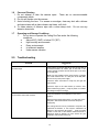
1.4
IR Remote Control
The IR Remote Control for the Ceiling DocCam requires 2 ‘AAA’ batteries. Pull
up the battery cover tab and insert the batteries, making sure the battery +/terminal symbols line up with the +/- symbols on the inside of the battery
compartment. The VideoLabs IR Remote controls Power ON/OFF, Zoom-in and
Zoom-out.
Other IR Remote Controls
The Ceiling DocCam can be ordered to respond to the zoom-in and zoom-out
commands of the Polycom® ViewStation IR Remote and the PictureTel® IR
Keypad. Please see the VideoLabs Price List for model numbers and ordering
information.
1.5
RS-232 Control
The Ceiling DocCam is equipped with a RS-232 control interface on a RJ-45
Jack (Figure 13). See Appendix 1 for RS-232 control interface.
(NOTE: All ASCII commands require “carriage return” at the end of each statement)
Figure 13: RS-232 Control Jack and Pin-out Table
RS-232
Interface
Pins 5 & 6 - GND
PIN 7 - RXD
PIN 1 – Not Used
RS-232 Pin-outs
Pin 1
Pin 2
Pin 3
Pin 4
Pin 5
Pin 6
Pin 7
Pin 8
PIN 8 - TXD
Not Used
Not Used
Not Used
Not Used
GND
GND
RXD
TXD
RS-232 Jack
9
1.6
1.
2.
3.
4.
Care and Cleaning
Do not attempt to take the camera apart. There are no user-serviceable
components inside.
Do not spill liquids onto the camera.
Avoid touching the lens. For smears or smudges, clear any dust with a blower
and wipe stains with a glass cleaner and clean, soft cloth.
To clean exterior of camera, wipe with a clean damp cloth. Do not use any
abrasive chemicals.
1.7
Operating and Storage Conditions
1.
Do not store or operate the Ceiling DocCam under the following
conditions:
♦
Above 40ºC (104ºF) or below 0ºC (32ºF)
♦
High humidity environments
♦
Dusty environments
♦
In inclement weather
♦
Under severe vibration
2.0
Troubleshooting
Problem
No Video Image
Suggestion
Verify that the 50’ plenum rated RJ-45 plug-to-plug cable is
connected between the “MAIN” jack on the back of the
camera module enclosure and the RJ-45 jack on the back
of the wall plate.
Make sure the provided 12VDC power supply is plugged
into a wall outlet and the “12 V DC” jack on the wall plate.
Do not use any other power supply.
Check the video connections to verify they are tight and
fully inserted.
Check the input on the video device (ie...monitor, VCR,
video conferencing system...), verify it’s power-on condition
and assign the input accordingly.
The IR remote control does not work.
Verify fresh batteries are installed and in the correct
position.
Remove power supply plug from the “12 V DC” jack on the
wall plate. Wait a few seconds and reinsert the power
supply plug.
The Ceiling DocCam can be purchased to respond to the
VideoLabs IR Remote, or the Polycom ViewStation IR
Remote or the PictureTel IR Keypad.
Verify the model
number on the back of the camera module enclosure to
determine which IR Remote you have chosen for your
installation and use that remote only.
10
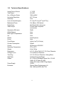
3.0 Technical Specifications:
Image Pick-up Device
Total Pixels
No. of Effective Pixels
Horizontal Resolution
Sensitivity
Lens: (Horizontal angle)
Mechanical Zoom
Digital Zoom
Video Output
Illumination S/N (min)
White Balance
Back Light Compensation
Iris
Shutter
Focus
Focal Range
Current Consumption
Control
Operating Temperature
Weight
Dimensions
Ceiling Cut-out
Trim Ring
Wall Plate
Cables
Power Supply
Enclosure
¼ ” CCD
410,000
768H x 494V
470 TV lines
3 lux
F1.6 (w)-F3.8 (t) [470 (w)-2.20(t)]
F=4-88mm; 22X Optical,
44X Digital (X2 continuous)
S-Video and Composite
(concurrent)
50dB
Auto
Auto
Auto
Auto Exposure
Auto
Infinity-1m(T)-0.01m(w)
300mA
IR Remote or RS-232C
0oC to 40oC
4 lbs/1.81kg
4.5” (11.43cm) Tall & 6.5” (16.51cm) Diameter
3.5” (8.89cm) in Diameter
5.5” (13.97cm) in Diameter, Ceiling White
S-Video/Composite/Power
50’ (15.24 m) Shielded Plenum Cat. 5 RJ-45
Cable, 25’ S-Video (S-VHS)
Cable, RCA Jack to BNC Plug Adapter
12VDC
Plenum Rated Conforming to UL
Std. 1480 and NFPA Std. 72A
11
4.0
Warranty Information on Hardware
VideoLabs warrants this product against defects in materials and workmanship for a
period of one (1) year from the date of purchase. If VideoLabs receives notice of such
defects during the warranty period, VideoLabs will either, at its option, repair or replace
products which prove to be defective.
Obtaining Warranty Service
To obtain warranty service, products must be returned to a service facility designated by
VideoLabs.
Customer shall prepay shipping charges for products returned to
VideoLabs for warranty service and VideoLabs shall pay for return of the products to
customer. However, customer shall pay all shipping charges, duties and taxes for
products returned to VideoLabs from another country.
VideoLabs Customer Service
If the camera is still under warranty, VideoLabs will test, repair or replace the product
without charge. If the camera is out-of-warranty, VideoLabs will test, then repair the
product for the cost of parts and labor. Charges will be estimated and confirmed by the
customer prior to repair by a VideoLabs’ technician.
Repair time for all cameras is a maximum of 2 business days from receiving to
outbound shipping. VideoLabs will not accept responsibility for shipment after the
camera has left our premises.
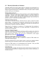
VideoLabs Technical Support
VideoLabs’ technicians will determine and discuss with the customer the criteria for
repair costs and/or replacement. Contact VideoLabs’ Technical Support through one of
these sources: phone: 800-467-7157 (U.S. only) or 763-542-0061, e-mail: support
@videolabs.com or web site: www.videolabs.com
RMA (Return Merchandise Authorization) Number
Before returning a camera for repair or replacement, request an RMA number from
VideoLabs Technical Support.
Provide the technician with a return phone number or email and a shipping address.
Describe the product, the reason for repair or return, and the date of purchase.
Include your RMA number on all correspondence with VideoLabs. Write your RMA
number on the outside of the box when you return the camera.
Voided Warranty
This warranty does not apply if the VideoLabs serial number has been removed or if the
product has been disassembled or damaged through misuse, accident, modifications, or
unauthorized repair.
12
Shipping and Handling
VideoLabs will not pay for inbound shipping, transportation, or insurance charges, or
accept any responsibility for loss and/or damage from inbound transit. VideoLabs
requires that all overseas returns are shipped via UPS.
VideoLabs will pay for outbound shipping, transportation, and insurance charges but will
not assume responsibility for loss and/or damage by the outbound freight carrier.
Products Not Under Warranty
Payment arrangements are required before outbound shipping for all products that are
out-of-warranty.
Exclusions
The above warranty shall not apply to defects resulting from: improper or inadequate
maintenance or installation by customer, customer-supplied software or interfacing;
unauthorized modifications or misuse; operation outside of the environment
specifications for the product; or improper site operation and maintenance.
All statements, technical information, and recommendations related to VideoLabs
products are based on information believed to be reliable. Before using this product,
you must evaluate it and determine if it is suitable for your intended application. You
assume all risks and liability associated with such use.
VideoLabs MAKES NO OTHER WARRANTIES INCLUDING, BUT NOT LIMITED TO,
ANY IMPLIED WARRANTY OF MERCHANTABILITY OR FITNESS FOR A
PARTICULAR PURPOSE.
Limitation of Liability
Except where prohibited by law, VideoLabs will not be liable for any loss or damage
arising from this product, whether direct, indirect, special, incidental or consequential
regardless of the legal theory asserted.
13
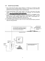
5.0
Quick Connect Guide
1. First connect the 50’ plenum rated, Category 5, RJ-45 plug to RJ-45 plug cable
between the RJ-45 jack labeled MAIN on the back of the camera module enclosure
and the RJ-45 jack on the back of the provided wall plate.
2. Connect the provided 12VDC power supply to the jack on the front of the plate
labeled 12 V DC and plug the power supply into a standard 110V-120V electrical
outlet. Use only the provided 12VDC power supply.
3. Connect the Output jacks labeled S-VIDEO or COMPOSITE to the Inputs of video
devices such as video conferencing systems, monitor/receivers, VCRs, LCD and
DLP projectors, video switchers, video capture cards, video to USB adapters etc..
Note: Both S-VIDEO and COMPOSITE outputs are live.
4. Put Batteries in the IR Remote Control and turn the camera ON.
5. Use the IR Remote Control to zoom in & out on the document/object positioned
under the Ceiling DocCam.
50’ Plenum Rated, Category 5, RJ-45 plug to
RJ-45 Plug Cable. Attach between MAIN
RJ-45 Jack on Camera Enclosure and RJ-45
Jack on the Rear of the Wall Plate.
RJ-45
Ceiling DocCam
Camera Module
Enclosure, Tile
Support Rails and
Trim Ring
Suspended Ceiling
Example:
Video
Monitor
Comp.
Video
Power and
Video Wall
Plate
12 V DC
Power
Supply
RJ-45
Table or Work Surface Directly
Under Ceiling DocCam
S-Video
Example: Video
Conferencing System
14
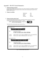
Appendix 1 - RS-232C Control Information
1. Communication protocol
Communication between the microcomputer of the camera and the PC is available by using the
RS-232C protocol. The microcomputer receives each control command given by the PC and
echoes it back to the PC.
2. Connect condition
Data length
Stop bit
Parity
Baudrate
8 bit
1 bit
even
4800 bps
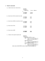
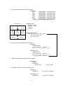
3. Communication data format
All communication data consists of eight or ten ASCII characters (8 bytes or 10 bytes).
Communication data starts with the character ":" (colon).
Enter
NOTE: All ASCII commands require “carriage return”
at the end of each statement.
The format of the communication data is shown in Fig. 1.
(a) 8 bytes format
1st byte
: CM A3 A2
8th byte
A1 A0 D1 D0
CM
Command as follows
R :Read 1 byte data of µCom. RAM or EEPROM
W :Write 1 byte data of µCom. RAM or EEPROM
A3-A0
D1-D0
Address data of µCom. RAM or EEPROM (write in hex. 0000-FFFF)
Data of µCom. RAM or EEPROM (write in hex. 00-FF)
(b) 10 bytes format
1st byte
: CM A3 A2
10th byte
A1 A0 D3 D2 D1 D0
CM
Command as follows
r :Read 2 bytes data of µCom. RAM or EEPROM
w :Write 2 bytes data of µCom. RAM or EEPROM
A3-A0
D3-D0
Address data of µCom. RAM or EEPROM (write in hex. 0000-FFFF)
Data of µCom. RAM or EEPROM (write in hex. 0000-FFFF)
Fig. 1 Communication data format
15
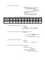
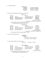
4. Control commands
a)
Switch the auto focus / manual focus
:RFF0E00
:WFF0EX1X0
bit 3 of X1X0
or
:WFCBBA8
:WFCBBFE
b)
c)
d)
e)
f)
: 0-Auto 1-Manual
;Change
;Neutral
Move focus to FAR in manual focus mode
:WFCBBA9
:WFCBBFE
;Start
;Stop
:WFCBBAA
:WFCBBFE
;Start
;Stop
:WFCBB99
:WFCBBFE
;Start
;Stop
:WFCBB9B
:WFCBBFE
;Start
;Stop
Move focus to NEAR in manual focus mode
Move zoom to TELE
Move zoom to WIDE
Select the zoom speed of optical zoom
:RFDFC00
:WFDFCX1X0
Super HIGH SPEED (2.4 sec) * ;
X1X0 : Set bit 3 of echo back data to “0”.
Set bit 2 of echo back data to “1”.
HIGH SPEED (3.9 sec);
X1X0 : Set bit 3 of echo back data to “0”.
Set bit 2 of echo back data to “0”.
NORMAL SPEED (6.3 sec);
X1X0 : Set bit 3 of echo back data to “1”.
Set bit 2 of echo back data to “0”.
*[Note]: Super HIGH SPEED (2.4sec) for Zoom Trace Preset Mode only
16
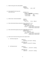
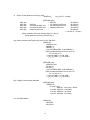
g)
Get the status of zoom position
:RFC9100
If echo back data is not “FF”, zoom position
is calculated by following equation.
zoom position = 22X256/(XX+1)
XX; echo back data
If echo back data is “FF”, then following
commands should be sent.
:rF7200000
Echo back data shows zoom position.
[Please refer to the attached Table.1.]
Table.1 Zoom position data table (reference value)
X3
X4
X5
X6
X7
X8
Zoom position
X1
X2
Echoback data
14BA
or less
2DDD
or less
3A56
or less
422D
or less
47C7
or less
4C15
or less
4F96
or less
528E
or less
X9
X10
X11
5517
or less
575B
or less
5953
or less
Zoom position
X12
X13
X14
X15
X16
X17
X18
X19
X20
X21
X22
Echoback data
5B20
or less
5CB1
or less
5E18
or less
5F4B
or less
605D
or less
6143
or less
6208
or less
62AA
or less
6333
or less
63A2
or less
63A2
or more
h)
Switch the continuous digi. zoom ON/OFF
:RFCCB00
:WFCCBX1X0
X1X0=00 ; OFF X1X0=01 ; ON (default)
Please attached Continuous digi. zoom flow chart.
i)
Set the maximum mag. tuning value in continuous digi. zoom ON mode
:WFDF0X1X0
X1X0 (hex) = {256-(256/MM)} (dec)
MM; maximum mag.
[ EX. mag.1; MM=1 X1X0=00
mag.2; MM=2 X1X0=80 ; max. (default)
j)
Switch the instant digital zoom ON/OFF
:RFF0F00
:WFF0FX1X0
bit 7 of X1X0
k)
: 0-OFF(default) 1-ON
Set the instant mag. tuning value in instant digi. zoom ON mode
:WFDE6X1X0
X1X0 (hex) = IMX10(dec)
IM; instant mag.
(more than 1.0 and 0.1 step)
[ EX.
mag.1; IM=1.0 X1X0=0A
mag.2; IM=2.0 X1X0=14 ; max. ]
17
l)
Switch the auto gain control (AGC) ON/OFF
:RFB7F00
:WFB7FX1X0
bit 7 of X1X0
m) Set the fixed AGC level tuning value
in AGC OFF mode
n)
: 0-ON 1-OFF
:wFB38X3X2X1X0
X3X2X1X0 : tuning value
( X3X2X1X0=0000~03C0 ; 0.03125dB/step )
[ X3X2X1X0=0000
; 0dB ,
X3X2X1X0=03C0
; 30dB ]
Switch the auto / manual white balance
:RFBFF00
:WFBFFX1X0
bit 3 of X1X0
: 0-Auto 1-Manual
o)
Set the white balance (R gain) tuning value in manual white balance mode
:wFBBCX3X2X1X0
X3X2X1X0 : tuning value
( min. H’0080, max. H’03FF )
X3X2X1X0: H’0080~H’00FF, H’0180~H’01FF,
H’0280~H’02FF, H’0380~H’03FF
p)
Set the white balance (B gain) tuning value in manual white balance mode
:wFBBEX3X2X1X0
X3X2X1X0 : tuning value
( min. H’0080, max. H’03FF )
X3X2X1X0: H’0080~H’00FF, H’0180~H’01FF,
H’0280~H’02FF, H’0380~H’03FF
q)
Set the auto iris control level tuning value in auto exposure mode
i)
Iris offset (average) level
[RAM area]
:WFD9EX1X0 ( X1X0=00~FF ; 256 step )
[EEPROM area] *
:WE09EX1X0 ( X1X0=00~FF ; 256 step )
ii)
Iris offset (peak) level
[RAM area]
:WFD9FX1X0
( X1X0=00~7F ; 128 step )
[EEPROM area] *
:WE09FX1X0
( X1X0=00~7F ; 128 step )
18
r)
Get the luminance data for the 6 screen areas
[RAM area]
area 1
:RFAE0000000 ; data length 3Byte
area 2
:RFAE3000000 ; data length 3Byte
area 3
:RFAE6000000 ; data length 3Byte
area 4
:RFAE9000000 ; data length 3Byte
area 5
:RFAEC000000 ; data length 3Byte
area 6
:RFAEF000000 ; data length 3Byte
[Note] This is the average data per one field.
< screen areas >
( area 1)
C
( area 5)
( area 3)
s)
A
D
( area 6)
B
( area 2)
C
( area 5)
( area 4)
< weighting areas >
A= area 1 + area 2
B= area 3 + area 4
C= area 5
D= area 6
< default weighting-ratio >
A:B:C:D = (Ka+1): (Kb+1): (Kc+1): (Kd+1)
= (4+1): (6+1): (9+1): (F+1)
= (5): (7): (10): (16)
Set the luminance weighting data tuning value
[RAM area]
:wFDA0X3X2X1X0
( X3=X2=X1=X0=0~F ; 16 step )
( X3 : K a , X2 : K b , X1 : K c , X0 : K d )
[EEPROM area] *
:wE0A0X3X2X1X0
( X3=X2=X1=X0=0~F ; 16 step )
( X3 : K a , X2 : K b , X1 : K c , X0 : K d )
[
X3X2X1X0=469F ; default ]
t)
Switch the back light compensation (BLC) ON/OFF
[RAM area]
:RFECE0
:WFECEX1X0
X1X0=00 ; OFF
u)
X1X0=02 ; ON
Set the BLC level tuning value in BLC ON mode
[RAM area]
:WFD8EX1X0
( X1X0=00~FF ; 256 step )
[EEPROM area] *
:WE08EX1X0
( X1X0=00~FF ; 256 step )
19
v)
Set the burst ON/OFF
[EEPROM area] *
:WE198X1X0
:WE199X1X0
:WE19AX1X0
:WE19BX1X0
( X1X0=00~FF ; 256 step )
( X1X0=00~FF ; 256 step )
( X1X0=00~FF ; 256 step )
( X1X0=00~FF ; 256 step )
w) Set the chroma suppression level tuning value in AGC range
[RAM area]
~ AGC ON
:WB790X4Y4
AGC ON
~ 1/3 maximum AGC level
:WB791X3Y3
1/3 maximum AGC level
~ 2/3 maximum AGC level
:WB792X2Y2
2/3 maximum AGC level
~ maximum AGC level
:WB793X1Y1
maximum AGC level
~
:WB794X0Y0
( X?X?=00~FF ; 256 step )
darker (H’00) < center (H’7F) < brighter (H’FF)
[Note] maximum AGC level setting at page 15 - item m)
chroma suppression level tuning values at Fig. 1
AGC gain
AGC gain
AGC gain
AGC gain
AGC gain
[EEPROM area] *
~ AGC ON
:W1340X4Y4
AGC ON
~ 1/3 maximum AGC level
:W1341X3Y3
1/3 maximum AGC level
~ 2/3 maximum AGC level
:W1342X2Y2
2/3 maximum AGC level
~ maximum AGC level
:W1343X1Y1
maximum AGC level
~
:W1344X0Y0
( X?X?=00~FF ; 256 step )
darker (H’00) < center (H’7F) < brighter (H’FF)
[Note] maximum AGC level setting at page 15 - item m)
AGC gain
AGC gain
AGC gain
AGC gain
AGC gain
x)
Select the manual aperture mode
[RAM area]
:RFBFF00
:WFBFFX1X0
X1X0 : Set bit 1 of echo back data to “1”.
[ bit 1 of X1X0 : 0-Auto 1-Manual ]
y)
Set the horizontal aperture level tuning value
:WFBF6X1X0
( X1X0=00~1F ; 32 step )
[EEPROM area] *
~ AGC ON
:W1350X4Y4
AGC ON
~ 1/3 maximum AGC level
:W1351X3Y3
1/3 maximum AGC level
~ 2/3 maximum AGC level
:W1352X2Y2
2/3 maximum AGC level
~ maximum AGC level
:W1353X1Y1
maximum AGC level
~
:W1354X0Y0
( X?X?=00~1F ; 32 step )
[Note] maximum AGC level setting at page 15 - item m)
horizontal aperture level tuning values at Fig. 2
AGC gain
AGC gain
AGC gain
AGC gain
AGC gain
20
z)
Set the vertical aperture level tuning value
:WFBF9X1X0
( X1X0=00~1F ; 32 step )
[EEPROM area] *
~ AGC ON
:W13A0X4Y4
AGC ON
~ 1/3 maximum AGC level
:W13A1X3Y3
1/3 maximum AGC level
~ 2/3 maximum AGC level
:W13A2X2Y2
2/3 maximum AGC level
~ maximum AGC level
:W13A3X1Y1
maximum AGC level
~
:W13A4X0Y0
( X?X?=00~1F ; 32 step )
[Note] maximum AGC level setting at page 15 - item m)
vertical aperture level tuning values at Fig. 3
AGC gain
AGC gain
AGC gain
AGC gain
AGC gain
aa) Set the maximum AGC gain tuning value in AGC ON mode
[RAM area]
:wFD46X3X2X1X0
:WB5B6Y1Y0
:WB5BCY1Y0
( X3X2X1X0=0000~0500 ; 0.03125dB/step )
[Note] condition between X3X2X1X0 and Y1Y0
Y1Y0 = X3X2X1X0 / 8
[ X3X2X1X0=0000, Y1Y0=00 ; 0dB ,
X3X2X1X0=0500, Y1Y0=A0; 40dB ]
[EEPROM area] *
:wE046X3X2X1X0
:W1166Y1Y0
:W116CY1Y0
( X3X2X1X0=0000~0500 ; 0.03125dB/step )
[Note] condition between X3X2X1X0 and Y1Y0
Y1Y0 = X3X2X1X0 / 8
[ X3X2X1X0=0000, Y1Y0=00 ; 0dB ,
X3X2X1X0=0500, Y1Y0=A0; 40dB ]
bb) Change Communication Baudrate
[EEPROM area] *
:WE05EX1X0
( X1X0=80 or 00
; 4800 bps , even Parity ; default
X1X0=B0 ; 9600 bps , even Parity
X1X0=C0 ; 4800 bps , non Parity
X1X0=F0 ; 9600 bps , non Parity )
cc) Set RAM initialize
[RAM area]
:WFF0A00
:WFCAC00
21
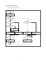
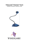
5. Other useful commands
a)
Continuous Digital Zoom Control
ZOOM OPERATION
ZOOM START
Get digi. zoom
:RFC91XX (XX:MAG)
XX=H ’FF?
Digi. Zoom on?
yes
no
Optical Zoom area
Digital Zoom area
no
ZOOM TELE?
ZOOM TELE?
yes
TELE
no
Continuous
digi. zoom ON?
yes
Continuous digi. zoom ON
:WFCCB01
yes
WIDE
Send zoom to tele command
:WFCBB99
TELE
no
Send digi. zoom tele command
:WBFBB08
Send zoom to wide command
:WFCBB9B
no
no
Zoom stop?
Zoom stop?
yes
yes
Send digi. zoom stop command
:WBFBB00
Send zoom stop command
:WFCBBFE
ZOOM END
Fig. 1 CONTINUOUS DIGITAL ZOOM FLOW CHART
22
WIDE
Send digi. zoom wide command
:WBFBB04