1
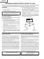
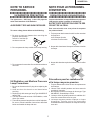
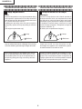
XG-MB70X A
SERVICE MANUAL
SX5Q3XGMB70XA
MULTIMEDIA-PROJECTOR
MODEL
XG-MB70X A
In the interests of user-safety (Required by safety regulations in some countries) the set should be restored to its original condition and only parts identical to those specified should be used.
OUTLINE
This Service Manual covers only different points from Model XG-MB70X. For other technical points,
refer to the XG-MB70X Service Manual.
CONTENTS
Page
»
»
»
»
»
»
»
»
»
»
»
SPECIFICATIONS .........................................................................................................................................2
A COMPARISON TABLE WITH THE UNIT OF XG-MB70X A ...................................................................... 3
IMPORTANT SERVICE SAFETY NOTES (FOR USA) ................................................................................ 4
NOTE TO SERVICE PERSONNEL ..............................................................................................................5
BALLAST UNIT OUTPUT POWER (LAMP OUTPUT) ADJUSTMENT ....................................................... 9
TROUBLESHOOTING TABLE ...................................................................................................................10
DESCRIPTION OF SCHEMATIC DIAGRAM .............................................................................................13
SCHEMATIC DIAGRAM .............................................................................................................................14
PRINTED WIRING BOARD ASSEMBLIES................................................................................................20
PARTS LIST ...............................................................................................................................................24
PACKING OF THE SET .............................................................................................................................34
SHARP CORPORATION
This document has been published to be used for
after sales service only.
The contents are subject to change without notice.
XG-MB70X A
SPECIFICATIONS
Product type
Model
Video system
Multimedia Projector
XG-MB70X
NTSC3.58/NTSC4.43/PAL/PAL-M/PAL-N/PAL-60/SECAM/
DTV480I/DTV480P/DTV540P/DTV576I/DTV576P/DTV720P/DTV1035I/DTV1080I
Display method Single Chip Digital Micromirror DeviceTM (DMDTM) by Texas Instruments
DMD panel Panel size: 0.7"
No. of dots: 786,432 dots (1,024 [H] ✕ 768 [V])
Lens 1.5 ✕ electric zoom / focus lens, F2.0–2.5, f = 21.3–31.6 mm
Projection lamp 275 W DC lamp
Component input (INPUT 1/2)/ 15-pin mini D-sub connector
output (OUTPUT) signal Y: 1.0 Vp-p, sync negative, 75 Ω terminated
PB: 0.7 Vp-p, 75 Ω terminated
PR: 0.7 Vp-p, 75 Ω terminated
Horizontal resolution 750 TV lines (DTV720P)
Computer RGB input (INPUT 1/2)/ 15-pin mini D-sub connector
output (OUTPUT) signal RGB separate/sync on green type analog input: 0–0.7 Vp-p, positive, 75 Ω terminated
HORIZONTAL SYNC. SIGNAL: TTL level (positive/negative)
VERTICAL SYNC. SIGNAL: Same as above
Video input signal RCA connector: VIDEO, composite video, 1.0 Vp-p, sync negative, 75 Ω terminated
(INPUT 3)
S-video input signal 4-pin mini DIN connector
(INPUT 4) Y (luminance signal): 1.0 Vp-p, sync negative, 75 Ω terminated
C (chrominance signal): Burst 0.286 Vp-p, 75 Ω terminated
Audio input signal ø3.5 mm minijack: AUDIO, 0.5 Vrms, more than 22 kΩ (stereo)
USB terminal 4-pin B-type USB female connector
RS-232C terminal 9-pin mini DIN connector
LAN terminal 8-pin RJ-45 modular connector
Pixel clock 12–108 MHz
Vertical frequency 43–85 Hz
Horizontal frequency 15–70 kHz
Audio output 2.0 W (monaural)
Speaker system 4.0 cm ✕ 2.85 cm oval ✕1
Rated voltage AC 100–240 V
Input current 3.9 A
Rated frequency 50/60 Hz
Power consumption 370 W (Standard mode)/320 W (Eco mode) with AC 100 V
350 W (Standard mode)/300 W (Eco mode) with AC 240 V
Power consumption (standby) 6 W (AC 100 V) – 8 W (AC 240 V)
Heat dissipation 1,390 BTU/hour (Standard mode)/1,200 BTU/hour (Eco mode) with AC 100 V
1,315 BTU/hour (Standard mode)/1,130 BTU/hour (Eco mode) with AC 240 V
Operating temperature 41°F to 104°F (+5°C to +40°C)
Storage temperature –4°F to 140°F (–20°C to +60°C)
Cabinet Plastic
I/R carrier frequency 38 kHz
Dimensions (approx.) 12 7/32" ✕ 3 33/64" ✕ 11 7/64" (310 (W) ✕ 89 (H) ✕ 282 (D) mm) (main body only)
12 7/32" ✕ 4 7/64" ✕ 11 5/16" (310 (W) ✕ 104 (H) ✕ 287 (D) mm) (including adjustment foot and projecting parts)
Weight (approx.) 9.1 lbs. (4.1 kg)
Replacement parts Lamp unit (Lamp/cage module) (AN-MB70LP), Remote control (RRMCGA313WJSA), Power cord for U.S.,
Canada, etc. (QACCDA007WJPZ), Power cord for Europe, except U.K. (QACCVA011WJPZ), Power cord for
U.K., Hong Kong and Singapore (QACCBA036WJPZ), Power cord for Australia, New Zealand and Oceania
(QACCLA018WJPZ), RGB cable (QCNWGA045WJPZ), USB cable (QCNWGA014WJPZ), Storage case
(GCASNA014WJSA), Lens cap (RCAPHA021WJSA), Projector manual and technical reference CD-ROM
(UDSKAA072WJZZ), “QUICK GUIDE” label (TLABZA717WJZZ), Operation manual (TiNS-C177WJZZ)
As a part of policy of continuous improvement, SHARP reserves the right to make design and
specification changes for product improvement without prior notice. The performance specification figures indicated are nominal values of production units. There may be some deviations from
these values in individual units.
2
XG-MB70X A
A COMPARISON TABLE WITH THE UNIT OF XG-MB70X A
XG-MB70X
Ref. No.
Parts No.
DUNTKC612WEF0
XG-MB70X A
Change
★
→
J
DUNTKC613WEF0
Parts No.
DUNTKC612WEF5
←
J
Description
Code
MAIN Unit
CU
FORMATTER Unit
CK
DUNTKC615WEF0
→
J
DUNTKC615WEF5
FRONT R/C Unit
AN
DUNTKC681WEF0
→
J
DUNTKC681WEF5
REAR R/C Unit
AN
RDENCA082WJZZ
→
J
DUNTKD556WEF1
POWER SUPPLY Unit
BR
→
J
DSETUD496FMF2
BALLAST POWER Unit
–
DUNTKD496WEF2
BALLAST Unit
or
RDENCA118WJZZ
RDENCA088WJZZ
–
When you exchange a ballast unit
(DUNTKD496WEF2),
please order a ballast power supply unit
(DSETUD496FMF2).
J
DUNTKD497FMF2
BALLAST Control Unit
RUNTKA090WJZZ
J
←
CMOS CAMERA Unit
BS
RUNTKA091WJZZ
J
←
PHOTO SENSOR Unit
AZ
3
XG-MB70X A
IMPORTANT SERVICE SAFETY NOTES (for USA)
Ë Service work should be performed only by qualified service technicians who are
thoroughly familiar with all safety checks and servicing guidelines as follows:
» Use an AC voltmeter with sensitivity of 5000 ohm per
volt., or higher, sensitivity to measure the AC voltage
drop across the resistor (See Diagram).
» All checks must be repeated with the AC plug
connection reversed. (If necessary, a non-polarized
adapter plug must be used only for the purpose of
completing these checks.)
Any reading of 0.3 volts RMS (this corresponds to 0.2
milliamp. AC.) or more is excessive and indicates a
potential shock hazard which must be corrected before
returning the unit to the owner.
WARNING
1. For continued safety, no modification of any circuit
should be attempted.
2. Disconnect AC power before servicing.
CAUTION: FOR CONTINUED PROTECTION
AGAINST RISK OF FIRE REPLACE ONLY
WITH SAME TYPE F701 (6.3A, AC250V)
BEFORE RETURNING THE PROJECTOR:
(Fire & Shock Hazard)
Before returning the projector to the user, perform
the following safety checks:
1. Inspect lead wires are not pinched between the chassis
DVM
and other metal parts of the projector.
AC SCALE
2. Inspect all protective devices such as non-metallic
1.5k ohm
control knobs, insulating materials, cabinet backs,
10W
adjustment and compartment covers or shields,
isolation resistor-capacity networks, mechanical
insulators, etc.
3. To be sure that no shock hazard exists, check for
0.15 µF
TEST PROBE
current leakage in the following manner:
» Plug the AC cord directly into a 120-volt AC outlet, (Do
not use an isolation transformer for this test).
» Using two clip leads, connect a 1.5k ohm, 10 watt
TO EXPOSED
CONNECT TO
resistor paralleled by a 0.15µF capacitor in parallel
METAL PARTS
KNOWN EARTH
GROUND
between all exposed metal cabinet parts and earth
ground.
12345678901234567890123456789012123456789012345678901234567890121234567890123456789012345678901212
12345678901234567890123456789012123456789012345678901234567890121234567890123456789012345678901212
12345678901234567890123456789012123456789012345678901234567890121234567890123456789012345678901212
SAFETY NOTICE
AVIS POUR LA SECURITE
Many electrical and mechanical parts in DMD™
Projector have special safety-related characteristics.
These characteristics are often not evident from visual
inspection, nor can protection afforded by them be
necessarily increased by using replacement components
rated for higher voltage, wattage, etc.
Replacement parts which have these special safety
characteristics are identified in this manual; electrical
components having such features are identified by “å”
and shaded areas in the Replacement Parts Lists and
Schematic Diagrams. For continued protection,
replacement parts must be identical to those used in
the original circuit. The use of a substitute replacement
parts which do not have the same safety characteristics
as the factory recommended replacement parts shown
in this service manual, may create shock, fire or other
hazards.
De nombreuses pièces, électriques et mécaniques, dans
les projecteur à DMD™ présentent des caractéristiques
spéciales relatives à la sécurité, qui ne sont souvent pas
évidentes à vue.
Le degré de protection ne peut pas être nécessairement
augmentée en utilisant des pièces de remplacement
étalonnées pour haute tension, puissance, etc.
Les pièces de remplacement qui présentent ces
caractéristiques sont identifiées dans ce manuel;
les pièces électriques qui présentent ces particularités
sont identifiées par la marque “å” et hachurées dans la
liste des pièces de remplacement et les diagrammes
schématiques. Pour assurer la protection, ces pièces
doivent être identiques à celles utilisées dans le circuit
d’origine. L’utilisation de pièces qui n’ont pas les mêmes
caractéristiques que les pièces recommandées par l’usine,
indiquées dans ce manuel, peut provoquer des
électrocutions, incendies ou autres accidents.
WARNING: The bimetallic component has the primary
conductive side exposed. Be very careful in
handling this component when the power is on.
AVERTISSEMENT: La composante bimétallique dispose du
conducteur primaire dénudé. Faire attention
lors de la manipulation de cette
composante sous tension.
12345678901234567890123456789012123456789012345678901234567890121234567890123456789012345678901212
12345678901234567890123456789012123456789012345678901234567890121234567890123456789012345678901212
12345678901234567890123456789012123456789012345678901234567890121234567890123456789012345678901212
4
XG-MB70X A
NOTE TO SERVICE
NOTE POUR LE PERSONNEL
PERSONNEL
D’ENTRETIEN
123456789012345678901234567890121234567890123456 123456789012345678901234567890121234567890123456
123456789012345678901234567890121234567890123456
123456789012345678901234567890121234567890123456
UV-RADIATION PRECAUTION
123456789012345678901234567890121234567890123456
123456789012345678901234567890121234567890123456
PRECAUTION POUR LES RADIATIONS UV
123456789012345678901234567890121234567890123456
123456789012345678901234567890121234567890123456
The light source, UHP lamp, in the LCD projector
emits small amounts of UV-Radiation.
La source de lumière, la lampe UHP, dans le projecteur
LCD émet de petites quantités de radiation UV.
AVOID DIRECT EYE AND SKIN EXPOSURE.
EVITEZ TOUTE EXPOSITION DIRECTE DES
YEUX ET DE LA PEAU.
To ensure safety please adhere to the following:
Pour votre sécurité, nous vous prions de respecter
les points suivants:
1. Toujours porter des lunettes de soleil lors d’un entretien
du projecteur
avec la lampe allumée
et le haut du coffret retiré.
1. Be sure to wear sun-glasses when servicing the
projector with the lamp
turned “on” and the top
enclosure removed.
2. Ne pas faire fonctionner la lampe à l’extérieur du boîtier
de lampe.
2. Do not operate the lamp outside of the lamp housing.
3. Ne pas faire fonctionner plus de 2 heures avec le coffret
retiré.
3. Do not operate for more than 2 hours with the enclosure
removed.
Précautions pour les radiations UV
et la lampe moyenne pression
UV-Radiation and Medium Pressure
Lamp Precautions
1. Toujours débrancher la fiche AC lors du remplacement
de la lampe.
2. Laisser l’unité refroidir pendant une heure avant de
procéder à l’entretien.
3. Ne remplacer qu’avec une lampe du même type. Type
AN-MB70LP, caractéristique 275W.
4. La lampe émet de petites quantités de radiation UVéviter tout contact direct avec les yeux.
5. La lampe moyenne pression implique un risque
d’explosion. Toujours suivre les instr uctions
d’installation décrites ci-dessous et manipuler la lampe
avec soin.
1. Be sure to disconnect the AC plug when replacing the
lamp.
2. Allow one hour for the unit to cool down before
servicing.
3. Replace only with same type lamp. Type AN-MB70LP
rated 275W.
4. The lamp emits small amounts of UV-Radiation, avoid
direct-eye contact.
5. The medium pressure lamp involves a risk of explosion.
Be sure to follow installation instructions described
below and handle the lamp with care.
5
XG-MB70X A
123456789012345678901234567890121234567890123456
123456789012345678901234567890121234567890123456
123456789012345678901234567890121234567890123456
123456789012345678901234567890121234567890123456
123456789012345678901234567890121234567890123456
123456789012345678901234567890121234567890123456
UV-RADIATION PRECAUTION (Continued)
123456789012345678901234567890121234567890123456
123456789012345678901234567890121234567890123456
123456789012345678901234567890121234567890123456
PRECAUTION POUR LES RADIATIONS UV (Suite)
123456789012345678901234567890121234567890123456
123456789012345678901234567890121234567890123456
123456789012345678901234567890121234567890123456
Lamp Replacement
Remplacement de la lampe
Note:
Remarque:
Since the lamp reaches a very high temperature during
units operation replacement of the lamp should be
done at least one hour after the power has been turned
off. (to allow the lamp to cool off.)
Installing the new lamp, make sure not to touch the
lamp (bulb) replace the lamp by holding its reflector
2.
[Use original replacement only.]
Comme la lampe devient très chaude pendant le
fonctionnement de l’unité, son remplacement ne doit
être effectué au moins une heure après avoir coupé
l’alimentation (pour permettre à la lampe de refroidir).
En installant la nouvelle lampe, s’assurer de ne pas
toucher la lampe (ampoule). Remplacer la lampe en
tenant son réflecteur 2.
[N’utiliser qu’un remplacement d’origine.]
1 Lampe
1 Lamp
2 Reflecteur
2 Reflector
DANGER ! –– Never turn the power on without the
lamp to avoid electric-shock or damage of the devices
since the stabilizer generates high voltages at its start.
DANGER ! –– Ne jamais mettre sous tension sans la
lampe pour éviter un choc électrique ou des
dommages des appareils car le stabilisateur génère
de hautes tensions à sa mise en route.
Since small amounts of UV-radiation are emitted
from an opening between the exhaust fans, it is recommended to place the cap of the optional lens on
the opening during servicing to avoid eye and skin
exposure.
Comme de petites quantités de radiation UV sont
émises par une ouverture entre les ventilateurs aspirants, il est recommandé de placer le capuchon de
l’optique optionnelle sur l’ouverture pendant l’entretien
pour éviter une exposition des yeux et la peau.
6
XG-MB70X A
WARNING:
High brightness light source, do not stare into the beam of light, or view directly. Be especially
careful that children do not stare directly in to the beam of light.
WARNING:
TO REDUCE THE RISK OF FIRE OR ELECTRIC SHOCK, DO NOT EXPOSE THIS UNIT TO
MOISTURE OR WET LOCATIONS.
CAUTION
The lighting flash with arrowhead within a
triangle is intended to tell the user that
parts inside the product are risk of electric
shock to persons.
RISK OF ELECTRIC SHOCK.
DO NOT REMOVE SCREWS
EXCEPT SPECIFIED USER
SERVICE SCREW.
CAUTION: TO REDUCE THE RISK OF ELECTRIC SHOCK,
DO NOT REMOVE CABINET.
NO USER-SERVICEABLE PARTS EXCEPT LAMP UNIT.
REFER SERVICING TO QUALIFIED SERVICE
PERSONNEL.
The exclamation point within a triangle is
intended to tell the user that important
operating and servicing instructions are in
the manual with the projector.
CAUTION
(POWER Unit)
6.3A 250V
For continued
protection against a
risk of fire, replace
only with same type
6.3A, AC250V fuse.
(F701)
12345678901234567890123456789012123456789012345678901234567890121234567890123456789012345678901212
12345678901234567890123456789012123456789012345678901234567890121234567890123456789012345678901212
AVERTISSEMENT: Source lumineuse de grande intensité. Ne pas fixer le faisceau lumineux ou le regarder
directement. Veiller particulièrement à éviter que les enfants ne fixent directement le
faisceau lumineux.
AVERTISSEMENT: AFIN D’EVITER TOUT RISQUE D’INCENDIE OU D’ELECTROCUTION, NE PAS PLACER
CET APPAREIL DANS UN ENDROIT HUMIDE OU MOUILLE.
ATTENTION
L’éclair terminé d’une flèche à l’intérieur
d’un triangle indique à l’utilisateur que les
pi‘eces se trouvant dans l’appareil sont
susceptibles de provoquer une décharge
électrique.
RISQUE
D’ÉLECTROCUTION. NE
PASR ETIRER LES VIS Á
L’EXCEPTION DE LA VIS DE
REPARATION UTILISATEUR
SPECIFIEES
Le point d’exclamation à l’intérieur d’un
triangle indique à l’utilisateur que les
instructions de fonctionnement et
d’entretien sont détaillées dans les
documents fournis avec le projecteur.
ATTENTION: POUR EVITER TOUT RISQUE
D’ELECTROCUTION, NE PAS RETIRER LE CAPOT.
AUCUNE DES PIECES INTERIEURES N’EST REPARABLE
PAR L’UTILISATEUR, A L’EXCEPTION DE L’UNITE DE
LAMPE. POUR TOUTE REPARATION, S’ADRESSER A UN
TECHNICIEN D’ENTRETIEN QUALIFIE.
PRECAUTION
(Unité de PUTSSANCE)
Pour une protection
continue contre un
risques d’incendie, ne
remplacer qu’avec un
fusible 6.3A,AC250V
6.3A 250V du même type.
(F701)
7
XG-MB70X A
Precautions for using lead-free solder
1 Employing lead-free solder
"PWBs" of this model employs lead-free solder. The LF symbol indicates lead-free solder, and is attached on the
PWBs and service manuals. The alphabetical character following LF shows the type of lead-free solder.
Example:
LFa
Indicates lead-free solder of tin, silver and copper.
2 Using lead-free wire solder
When fixing the PWB soldered with the lead-free solder, apply lead-free wire solder. Repairing with conventional
lead wire solder may cause damage or accident due to cracks.
As the melting point of lead-free solder (Sn-Ag-Cu) is higher than the lead wire solder by 40°C, we recommend you
to use a dedicated soldering bit, if you are not familiar with how to obtain lead-free wire solder or soldering bit,
contact our service station or service branch in your area.
3 Soldering
As the melting point of lead-free solder (Sn-Ag-Cu) is about 220°C which is higher than the conventional lead solder
by 40°C, and as it has poor solder wettability, you may be apt to keep the soldering bit in contact with the PWB for
extended period of time. However, since the land may be peeled off or the maximum heat-resistance temperature of
parts may be exceeded, remove the bit from the PWB as soon as you confirm the steady soldering condition.
Lead-free solder contains more tin, and the end of the soldering bit may be easily corroded. Make sure to turn on
and off the power of the bit as required.
If a different type of solder stays on the tip of the soldering bit, it is alloyed with lead-free solder. Clean the bit after
every use of it.
When the tip of the soldering bit is blackened during use, file it with steel wool or fine sandpaper.
Be careful when replacing parts with polarity indication on the PWB silk.
Lead-free wire solder for servicing
Part No.
ZHNDAi123250E
ZHNDAi126500E
ZHNDAi12801KE
★
J
J
J
Description
φ0.3mm
250g(1roll)
φ0.6mm
500g(1roll)
φ1.0mm
1kg(1roll)
8
Code
BL
BK
BM
XG-MB70X A
BALLAST UNIT OUTPUT POWER (LAMP OUTPUT) ADJUSTMENT
1. List of adjustment-related parts
When the following parts have been replaced, adjust the ballast unit output power (lamp output).
1
2
3
3'
4
5
Parts Name
Cement resistor
Control PWB
Ballast microprocessor (FLASH)
Ballast microprocessor (MASK)
5V regulator
PWM controller
Ref. No.
R922
--IC7707
IC7707
IC7704
IC7701
Parts Code
RR-WZA015WJZZ
DUNTKD497FMF2
RH-iXB384WJZZQ
RH-iXB390WJZZQ
VHiTA78L05F-1Y
VHiM51995AF-1Y
2. Adjustment tools
The following tools are required in order to adjust the ballast unit output power (lamp power).
1
2
Parts Name
Adjustment jig (resistance load 25Ω)
Connecting cord (conversion cable)
Parts Code
RUNTZA018WJZZ
QCNW-E008WJZZ
Maker
Asahi Tushin
SMK
3. Adjusting the ballast unit output power (lamp power)
Take the following procedure to adjust the ballast unit output power (lamp power).
[How to set up]
Ballast Unit
Lamp Cable
(QCNW-E190WJQZ)
Tester
(Voltage)
+
-
MB70X A
Projector
TP1
Adjustment Jig
(RUNTZA018WJZZ)
Connecting Cord
(QCNW-E008WJZZ)
TP2
[How to adjust]
1. Disconnect the MB70X A projector's ballast unit lamp cable from the lamp. Connect the cable to the connecting
cord (QCNW-E008WJZZ).
2. Connect the connecting cord (QCNW-E008WJZZ) to the adjustment jig (RUNTZA018WJZZ).
3. Hook up the tester's negative probe and positive probe to the TP1 and TP2, respectively, of the adjustment jig
(RUNTZA018WJZZ).
4. Turn on the power of the MB70X A projector.
5. Warm up the projector for longer than 60 seconds.
6. Adjust the variable control (R7728) of the ballast control PWB (DUNTKD497FMF2) to achieve the tester
reading of 83±0.5 V.
Specification: 83±0.5V
4. Precautions
1) Electric shock:
Be careful not to touch the adjustment jig's test points TP1 and TP2 during continuity because high voltage
and large current are applied at them.
2) Heat hazard:
Keep in mind that the adjustment jig's resistance load is hot during continuity.
3) Lamp cable connection:
Make sure the lamp cable and the connecting cord (QCNW-E008WJZZ) are tightly connected.
If they are poorly connected, smoke or fire may be caused due to an arc discharge.
9
XG-MB70X A
TROUBLESHOOTING TABLE
Checking the power unit
There is no voltage output
at P704.
NO
Check the MAIN PWB unit.
YES
Which output voltage line
fails?
Other
Check the T705, IC704 and
their peripheral circuits.
NO
Check the P701 or AC
cord.
13V, 6
Is AC voltage(90 ~ 264V)
applied across the P701
connector?
YES
Is AC voltage(90 ~ 264V)
applied across the P702 or
P703 connector?
Is the Bimetal SW open?
YES
Push the red button of the
bimetal.
NO
Is the fuse F701 open?
YES
Replace the F701.
NO
Is the resistor R717 open?
YES
Replace the R717.
NO
Is the fuse F705 open?
NO
Replace Power unit.
10
YES
Replace the F705.
XG-MB70X A
Lamp fails to light-up
Turn on the power switch.
Is discharging sound heard
from lamp?
YES
Is the lamp out of socket?
YES
Reconnect the lamp into
socket.
NO
Check the
microproccessor and its
peripheral circuits.
NO
NO
Replace the lamp.
Is the cooling fan running?
NO
Check the power supply
circuits.
NO
Check the power supply
circuits.
YES
Is DC 380V pin(4) & 20V
pin(1) voltage applied
between P901 connector
pins?
YES
Is LOW LEVEL voltage
applied between pins(1) and NO
(5) of ballast's P7702
connector.
Is the P7702 connector
disconnected?
YES
Replace the ballast.
YES
Reconnect it into socket
correctly.
11
XG-MB70X A
-MEMO-
12
XG-MB70X A
DESCRIPTION OF SCHEMATIC DIAGRAM
VOLTAGE MEASUREMENT CONDITION:
1. Voltages at test points are measured at the
supply voltage of AC 220V. Signals are fed by a color
bar signal generator for servicing purpose and the
above voltages are measured with a 20k ohm/V tester.
WAVEFORM MEASUREMENT CONDITION:
1. Waveforms at test points are observed at the supply
voltage of AC 220V. Signals are fed by a color bar
signal generator for servicing purpose.
INDICATION OF RESISTOR & CAPACITOR:
RESISTOR
1. The unit of resistance “Ω” is omitted.
(K=kΩ=1000 Ω, M=MΩ).
2. All resistors are ± 5%, unless otherwise noted.
(J= ± 5%, F= ± 1%, D= ± 0.5%)
3. All resistors are 1/10W, unless otherwise noted.
4. All resistors are Carbon type, unless otherwise noted.
W : Cement
C : Solid
S : Oxide Film
T : Special
N : Metal Coating
CAPACITOR
1. All capacitors are µF, unless otherwise noted.
(P=pF=µµF).
2. All capacitors are 50V, unless otherwise noted.
3. All capacitors are Ceramic type, unless otherwise
noted.
(ML): Mylar
(TA): Tantalum
(PF): Polypro Film
(ST): Styrol
CAUTION:
This circuit diagram is original one, therefore there may be a
slight difference from yours.
SAFETY NOTES:
1.DISCONNECT THE AC PLUG FROM THE AC
OUTLET BEFORE REPLACING PARTS.
2.SEMICONDUCTOR HEAT SINKS SHOULD BE
REGARDED AS POTENTIAL SHOCK HAZARDS
WHEN THE CHASSIS IS OPERATING.
IMPORTANT SAFETY NOTICE:
PARTS MARKED WITH “å” (
) ARE
IMPORTANT FOR MAINTAINING THE SAFETY OF
THE SET. BE SURE TO REPLACE THESE PARTS
WITH SPECIFIED ONES FOR MAINTAINING THE
SAFETY AND PERFORMANCE OF THE SET.
13
XG-MB70X A
XG-MB70X A
SCHEMATIC DIAGRAM
H
Ë POWER SUPPLY Unit
DUNTKD556WEF1
G
F
E
D
C
B
A
1
2
3
4
5
14
6
7
8
9
10
11
12
13
14
15
16
15
17
18
19
XG-MB70X A
XG-MB70X A
Ë BALLAST Unit
H
DUNTKD496WEF2
G
F
E
D
C
B
A
1
2
3
4
5
16
6
7
8
9
10
11
12
13
14
15
16
17
17
18
19
XG-MB70X A
XG-MB70X A
Ë BALLAST CONTROL Unit
H
G
F
E
D
C
B
DUNTKD497FMF2
A
1
2
3
4
5
18
6
7
8
9
10
11
12
13
14
15
16
19
17
18
19
XG-MB70X A
PRINTED WIRING BOARD ASSEMBLIES
H
G
F
E
D
C
B
A
POWER SUPPLY Unit (Side-A)
1
2
3
4
20
5
6
D
POWER SUPPLY Unit (Side-B)
1
2
3
4
21
R705
R730
D710
5
C701
C723
FB706
D706
R721
R764
R725
D707
R738
Q706
Q705
D708
R749
C739
R740
R742
R748
C729
R743
R737
C722
G
R704
IC702
R735
R752
R750
R756
R753
C736
R751
R754
R760
R759
R758
R757
H
R703
R731
E
C717
R736
C724
D705
IC902
R767 R768
C705
R711 C703 R766 R762 R708
R710
R732
C706
C713
C702
R702
R712
C708
D704
D722 R728
R718
R715
R706
R707
C718
C716
XG-MB70X A
R755
IC704
FB704
C719
D713
R733
F
D702
R763
FB705
C
B
A
POWER SUPPLY Unit (Chip Parts Side-B)
6
XG-MB70X A
H
G
BALLAST Unit (Side-A)
F
E
D
BALLAST Unit (Side-B)
C
R906
R907
R909
R910
C908
C905
C924
C907
R948
R918
R920
R919
R921
R949
C925
C909
R939
R915
R904
R945
R903
R902
R944
R938
R943
A
R940
R950
D912
C906
R914
Q905
Q906
D911
C922
R913
FB902
Q903
R901
R912
C904
R916
C902
C903
D902
C911
D904
R941
R942
R917
R908
FB901
R932
R935
C915
D901
R927
R933
C913
R934
R925
R926 R946
R928 R929 R930 R931 C910
B
R911
R924
R937
BALLAST Unit (Chip Parts Side-B)
1
2
3
4
22
5
6
XG-MB70X A
H
G
BALLAST CONTROL Unit (Side-A)
C7746 R7787
C7739
R7761
D7703
R7720
R7723 C7731 R7755
C7713
R7721
C7719
R7731
C7744
IC7709
R7762
D7712
Q7707
R7726
R7712
C7707
R7725 R7724
C7710
C7715
C7734
C7709
R7717
D7713
R7719
C7712
R7775 R7776
D7711
C7742
C7728
R7793
R7770
R7769
R7783
C7749
C7727
C7718
C7741
C7737
IC7707
R7784
C7750
R7728
C7752
X7701
C7745
D7714
R7772
F
IC7701
C7733
C7736
C7751
P7702
R7704
C7701
R7708
P7701
D7715
C7717
E
BALLAST CONTROL Unit (Chip Parts Side-A)
D
C
BALLAST CONTROL Unit (Side-B)
R7737
IC7705
R7744
R7745
R7740
R7747
R7751
R7757
R7743
R7774
R7760
R7778
Q7709
C7723
R7779
R7741 C7725
R7742 C7726
R7738
R7789
R7790
R7791
R7792
R7777
R7722
R7781
R7780
R7759
C7730
R7767
C7740 R7773 C7743
R7736
C7724
D7706
IC7704
R7795
R7794
R7796
C7722
C7721
Q7708
R7729
Q7706
C7738
Q7703
R7764
R7771
R7763
R7765
R7716
Q7705
R7732
R7727
C7716
R7734 R7766
R7733
Q7704
R7748
R7756
R7786 R7785
R7735
R7752
R7730
Q7711
R7714
R7701
R7788
D7704
C7708
D7702
D7701
R7753
Q7702
C7720
R7739
Q7701
R7713
R7718
C7711
R7711
C7735
D7705
R7706
C7704
R7707
B
R7703
R7705 C7702
R7710 C7706
C7703
R7715
R7709
R7702
C7705
R7749 R7746
R7750
R7758 R7754
A
BALLAST CONTROL Unit (Chip Parts Side-B)
1
2
3
4
23
5
6
XG-MB70X A
Ref. No.
Part No.
★
Description
PARTS LIST
Ref. No.
Code
INTEGRATED CIRCUITS
HOW TO ORDER REPLACEMENT PARTS
To have your order filled promptly and correctly, please furnish the
following informations.
in USA:
3. PART NO.
4. DESCRIPTION
5. CODE
6. QUANTITY
Description
Code
PRINTED WIRING BOARD ASSEMBLIES
Unit Code change
DUNTKC612WEF5
DUNTKC615WEF5
DUNTKC681WEF5
J MAIN Unit
J FRONT R/C Unit
J REAR R/C Unit
Unit composition change
DUNTKD556WEF1 J POWER SUPPLY Unit
DSETUD496FMF2 J BALLAST POWER Unit
DUNTKD496WEF2 – BALLAST Unit
Q702
Q704
Q705
Q706
VS2SK3687++-1
VS2SK3687++-1
VS2SA1797Q+-1Y
VS2SC3928AR-1Y
J
J
J
J
TA78L12F
STR-W6765N
HA17431UA-TL
FA5501AN-D1
AF
AL
AE
AQ
J
J
J
J
2SK3687
2SK3687
2SA1797Q
2SC3928AR
AS
AS
AD
AB
DIODES
★ MARK: SPARE PARTS-DELIVERY SECTION
★
VHiTA78L12F-1Y
VHiSTRW67652E
VHiHA17431U-1Y
VHiFA5501AN-1Y
å D701
D702
D703
D704
D705
D706
D707
D708
D709
D710
D711
D712
D713
D714
å D715
å D716
D717
D718
D722
in CANADA: Contact SHARP Electronics of Canada Limited
Phone (416) 890-2100.
Part No.
IC702
IC703
IC704
IC902
TRANSISTORS
Contact your nearest SHARP Parts Distributor.
For location of SHARP Parts Distributor,
Please call Toll-Free; 1-800-BE-SHARP
Ref. No.
Code
POWER SUPPLY UNIT
Parts marked with "å" are important for maintaining the safety of
the set. Be sure to replace these parts with specified ones for maintaining the safety and performance of the set.
2. REF. NO.
Description
DUNTKD556WEF1
PARTS REPLACEMENT
1. MODEL NUMBER
★
Part No.
CU
AN
AN
VHDD10XB60H-1
VHD1SS355//-1Y
RH-DXA073WJZZ
VHD1SS355//-1Y
VHDLi114+++-1Y
VHDRB160M40-1Y
VHDRB160M40-1Y
VHDD1FL20U/-1Y
RH-DX0066GEZZY
RH-EX1294CEZZY
RH-DX0066GEZZY
RH-DX0066GEZZY
VHDD1FL20U/-1Y
RH-DXA070WJZZY
RH-FXA003WJZZ
RH-FXA003WJZZ
RH-DX0459CEZZ
RH-DX0469CEZZ
VHD1SS355//-1Y
BR
BT
—
BD
No change
DUNTKC613WEF0
RUNTKA090WJZZ
RUNTKA091WJZZ
J FORMATTER Unit
J CMOS CAMERA Unit
J PHOTO SENSOR Unit
CK
BS
AZ
AL
AB
AM
AB
AC
AC
AC
AC
AC
AB
AC
AC
AC
AE
AD
AD
AE
AF
AB
J Varistor
AD
COILS AND TRANSFORMERS
When you exchange a ballast unit (DUNTKD496WEF2),
please order a ballast power supply unit (DSETUD496FMF2).
J BALLAST Control Unit
D10XB60H
1SS355
Diode, DXA073WJ
1SS355
Li114
RB160M40
RB160M40
D1FL20U
Diode, DX0066GE
Zener Diode, 27V
Diode, DX0066GE
Diode, DX0066GE
D1FL20U
Diode, DXA070WJ
PC123Y82
PC123Y82
Diode, DX0459CE
Diode, DX0469CE
1SS355
PACKAGED CIRCUIT
å VA701 RH-VXA018WJN1
DUNTKD497FMF2
J
J
J
J
J
J
J
J
J
J
J
J
J
J
J
J
J
J
J
å L702
å L703
L705
T704
å T705
RCiLFA178WJZZ
RCiLFA178WJZZ
RCiLPA546WJZZ
RCiLCA131WJZZ
RTRNWA242WJZZ
C702
C703
C704
C705
C706
å C707
VCKYCY1HB103KY
VCKYCY1HB102KY
RC-EZA922WJZZ
VCKYTV1EB474KY
VCKYCY1EB333KY
RC-FZA026WJZZ
J
J
J
J
J
J
C708
C709
C710
å C711
å C712
C713
C714
VCKYCY1HB222KY
RC-KZA271WJZZ
RC-KZA275WJZZ
RC-KZ0105GEZZ
RC-KZ0105GEZZ
VCKYTQ1HB224KY
RC-FZA124WJZZ
J
J
J
J
J
J
J
å C715
RC-FZA026WJZZ
J
VCKYTV1EB104KY
VCKYTV1EB104KY
VCKYTV1HB103KY
VCEA4A1VN476M+
VCEA4A1VN106M+
VCKYTV1HB222KY
VCKYTV1HB471KY
VCKYTV1HB103KY
VCEA4A1HN105M+
RC-KZA050WJZZ
J
J
J
J
J
J
J
J
J
J
J
J
J
J
J
Filter Coil
Filter Coil
Peaking Coil
High Frequency Choke Coil
Transformer
AK
AK
AH
AW
CAPACITORS
C716
C717
C718
C720
C721
C722
C723
C724
C725
C726
24
0.01
50V Ceramic
1000p 50V Ceramic
330
420V Electrolytic
0.47
25V Ceramic
0.033 25V Ceramic
0.47
275V
Metallized Plastic Film
2200p 50V Ceramic
470p 2kV Ceramic
1000p 2kV Ceramic
2200p 250V Ceramic
2200p 250V Ceramic
0.22
50V Ceramic
2.2
450V
Metallized Plastic Film
0.47
275V
Metallized Plastic Film
0.1
25V Ceramic
0.1
25V Ceramic
0.01
50V Ceramic
47
35V Electrolytic
10
35V Electrolytic
2200p 50V Ceramic
470p 50V Ceramic
0.01
50V Ceramic
1
50V Electrolytic
470p 3.15kV Ceramic
AA
AA
AU
AC
AA
AE
AA
AC
AD
AD
AD
AC
AG
AE
AB
AB
AA
AC
AC
AA
AA
AA
AB
AD
XG-MB70X A
Ref. No.
★
Part No.
Description
Code
Ref. No.
DUNTKD556WEF1
R765
R766
R767
R768
POWER SUPPLY UNIT (Continued)
C727
C728
C730
C731
C732
C733
C734
å C735
C736
C737
C738
C739
C740
C741
VCEA4A1VN107M+ J 100
35V Electrolytic
RC-FZ0010TAZZ
J 0.01
630V
Metallized Plastic Film
RC-KZ0105GEZZ
J 2200p 250V Ceramic
RC-KZ0105GEZZ
J 2200p 250V Ceramic
RC-EZ1208CEZZ
J 2200 10V Electrolytic
RC-KZ0384CEZZ+ J 1000p 1kV Ceramic
RC-KZ0384CEZZ+ J 1000p 1kV Ceramic
RC-KZ0105GEZZ
J 2200p 250V Ceramic
VCKYTV1EB104KY J 0.1
25V Ceramic
RC-EZ1238CEZZ
J 1000 25V Electrolytic
VCEA4A1VN476M+ J 47
35V Electrolytic
RC-KZA111WJZZY J 1
25V Ceramic
VCEA4A1VN106M+ J 10
35V Electrolytic
RC-FZA126WJZZ
J 0.1
450V
Metallized Plastic Film
AC
AC
RR-HZ0119CEZZY
VRS-CY1JF153FY
VRS-TQ2BD474FY
VRS-TQ2BD474FY
VRS-TQ2BD394FY
VRN-TV1JD394DY
VRN-TV1JD394DY
VRN-TV1JD394DY
VRN-CY1JF133DY
VRS-CY1JF103JY
VRD-RM2HD102JY
VRS-CY1JF820FY
VRS-SV2HC100JY
RMPTKA001WJZZ
VRS-CY1JF223JY
VRD-RM2HD563JY
VRD-RM2HD563JY
VRS-TQ2EF100JY
VRD-RM2HD563JY
RR-WZA012WJZZ
VRS-TQ2EF100JY
RR-WZA012WJZZ
VRS-CY1JF183JY
VRS-TV1JD103JY
VRS-TV1JD103JY
VRS-TQ2BD153JY
VRD-RM2HD221JY
VRS-TQ2BD101JY
VRS-TQ2BD102JY
VRS-TQ2BD103JY
VRS-TV1JD564JY
VRN-VV3AB3R9J
VRS-TV1JD564JY
VRN-VV3AB1R8J
VRS-TQ2BD103JY
VRS-TQ2BD332FY
VRS-VV3AB273J
VRS-VV3AB273J
VRS-VV3DB220J
VRS-TQ2BD103JY
VRS-TV1JD102JY
VRS-TV1JD222FY
VRS-TQ2BD102JY
VRS-TV1JD101FY
VRS-TQ2BD331FY
VRS-TV1JD272FY
VRS-TV1JD681FY
VRS-TQ2EF221JY
VRS-TQ2EF221JY
VRS-TQ2EF681JY
VRS-TQ2EF681JY
VRN-TV1JD394DY
VRS-TQ2EF101JY
VRS-TQ2EF101JY
J
J
J
J
J
J
J
J
J
J
J
J
J
J
J
J
J
J
J
J
J
J
J
J
J
J
J
J
J
J
J
J
J
J
J
J
J
J
J
J
J
J
J
J
J
J
J
J
J
J
J
J
J
J
★
VRN-VV3AB1R8J
VRN-TV1JD394DY
VRS-TQ2EF470JY
VRS-TQ2EF470JY
J
J
J
J
Description
1.8
390k
47
47
1W
1/10W
1/4W
1/4W
Metal Film
Metal Film
Metal Oxide
Metal Oxide
Code
AA
AB
AA
AA
MISCELLANEOUS PARTS
å RY701 RRLYDA008WJZZ
å F701
QFS-CA010WJZZ
F705
QFS-TA005WJZZ
FB704 RBLN-A007WJZZY
FB705 RBLN-A007WJZZY
FB706 RBLN-A007WJZZY
FB707 RBLN-0020CEZZ+
å FH701 QFSHD1013CEZZ+
å FH702 QFSHD1014CEZZ+
P701
QPLGAA005WJZZ
P702
QPLGN0269GEZZ
P703
QPLGN0269GEZZ
P704
QPLGNA049WJZZ
P705
QPLGNB470WJZZ
RDA701 PRDARA259WJFW
RDA702 PRDARA297WJFW
LUG702 QLUGHA002WJZZ
E701
LANGQA025WJFW
PRDARA303WJFW
QCNW-E104WJQZ
QCNW-E105WJPZ
QCNW-E106WJPZ
LX-BZ3100CEFN
LX-BZA044WJFU
XBSSN30P06000
AD
AD
AD
AC
AC
AD
AB
AE
AC
AC
AC
AE
RESISTORS
å R701
R702
R703
R704
R705
R706
R707
R708
R710
R711
R714
R715
R716
å R717
R718
R719
R720
R721
R722
R724
R725
R727
R728
R730
R731
R733
R734
R735
R736
R737
R738
R739
R740
R741
R742
R743
R744
R745
R746
R748
R750
R751
R752
R753
R754
R755
R756
R757
R758
R759
R760
R762
R763
R764
Part No.
High Voltage High Resistor AC
15k 1/16W Metal Oxide AA
470k 1/8W
Metal Oxide AA
470k 1/8W
Metal Oxide AA
390k 1/8W
Metal Oxide AA
390k 1/10W Metal Film
AB
390k 1/10W Metal Film
AB
390k 1/10W Metal Film
AB
13k 1/16W Metal Film
AB
10k 1/16W Metal Oxide AA
1k 1/2W
Carbon
AA
82 1/16W Metal Oxide AA
10 1/2W
Metal Oxide AB
Cement/thermal Fuse AH
3.9 5W
22k 1/16W Metal Oxide AA
56k 1/2W
Carbon
AA
56k 1/2W
Carbon
AA
10 1/4W
Metal Oxide AA
56k 1/2W
Carbon
AA
0.15 5W
Resistor Wire AE
10 1/4W
Metal Oxide AA
0.15 5W
Resistor Wire AE
18k 1/16W Metal Oxide AA
10k 1/10W Metal Oxide AA
10k 1/10W Metal Oxide AA
15k 1/8W
Metal Oxide AA
220 1/2W
Carbon
AA
100 1/8W
Metal Oxide AA
1k 1/8W
Metal Oxide AA
10k 1/8W
Metal Oxide AA
560k 1/10W Metal Oxide AA
3.9 1W
Metal Film
AA
560k 1/10W Metal Oxide AA
1.8 1W
Metal Film
AA
10k 1/8W
Metal Oxide AA
3.3k 1/8W
Metal Oxide AA
27k 1W
Metal Oxide AA
27k 1W
Metal Oxide AA
22 2W
Metal Oxide AA
10k 1/8W
Metal Oxide AA
1k 1/10W Metal Oxide AA
2.2k 1/10W Metal Oxide AA
1k 1/8W
Metal Oxide AA
100 1/10W Metal Oxide AA
330 1/8W
Metal Oxide AA
2.7k 1/10W Metal Oxide AA
680 1/10W Metal Oxide AA
220 1/4W
Metal Oxide AA
220 1/4W
Metal Oxide AA
680 1/4W
Metal Oxide AA
680 1/4W
Metal Oxide AA
390k 1/10W Metal Film
AB
100 1/4W
Metal Oxide AA
100 1/4W
Metal Oxide AA
25
J
J
J
J
J
J
J
J
J
J
J
J
J
J
J
J
J
J
J
J
J
J
J
J
J
Relay
AG
Fuse, T6.3AH/AC250V
AF
Thermal Fuse
AG
Ferrite Bead
AC
Ferrite Bead
AC
Ferrite Bead
AC
Ferrite Bead
AB
Fuse Holder
AC
Fuse Holder
AC
AC Plug, 2pin
AL
Lead Relay Plug, 2pin (BA) AB
Lead Relay Plug, 2pin (BB) AB
Lead Relay Plug, 10pin (BC) AD
Lead Relay Plug, 4pin (BM) AD
Heat Sink A
AE
Heat Sink A
Lug
AB
Inlet Bracket
AF
Heat Sink B
AH
(Hf)Power-Main
AM
(Lf)Power-Sw
AM
Power-Ballast
AR
Screw, x4
AA
Screw, x2
AA
Screw, x4
AA
XG-MB70X A
Ref. No.
★
Part No.
Description
Code
Ref. No.
DUNTKD496WEF2
R927
R928
R929
R930
R931
R932
R933
R934
R935
R936
R937
R938
R939
R940
R941
R942
R945
R946
R948
R949
BALLAST UNIT
TRANSISTORS
Q901
Q902
Q903
Q904
Q905
Q906
VS2SK2699++-1
VS2SK2699++-1
VS2SA2056++-1Y
VS2SK2640++-1
VS2SA1530AR-1Y
VS2SC3928AR-1Y
D902
D903
D904
D905
D906
D907
D908
D910
D911
D912
TH901
VHDRB160M40-1Y
RH-DXA078WJZZ
VHDU1JU44//-1Y
VHSG1VB22C+-1
RH-DXA062WJZZY
VHDFMVG2GS+-1
VHDFMVG2GS+-1
RH-DXA062WJZZY
VHDU1JU44//-1Y
VHD1SS355//-1Y
RH-HXA020WJZZ
L901
L902
L903
T901
T902
RCiLPA137WJZZ
RCiLCA119WJZZ
RCiLPA475WJZZ
RTRNZA102WJZZ
RTRNWA188WJZZ
C901
RC-FZA215WJZZ
C903
C904
C908
C909
C912
VCKYCY1EB473KY
RC-KZA111WJZZY
RC-KZA450WJZZY
RC-KZA450WJZZY
RC-FZA123WJZZ
C913
C915
C917
RC-KZA378WJZZY
VCKYCY1EF104ZY
RC-FZA126WJZZ
C918
C919
RC-KZA275WJZZ
RC-FZA126WJZZ
C920
C921
C922
C923
RC-KZA275WJZZ
RC-KZA275WJZZ
VCKYCY1HB103KY
RC-EZA770WJZZ
R901
R902
R903
R904
R905
R908
R911
R912
R913
R914
R915
R916
R917
R918
R919
R920
R921
R922
R924
R925
R926
VRS-TV1JD334FY
VRS-TV1JD334FY
VRS-TV1JD334FY
VRS-TV1JD123FY
VRN-VV3ABR22J
VRS-TQ2BD100FY
VRS-TV1JD103JY
VRS-TQ2EF220JY
VRS-TQ2EF100JY
VRS-TQ2BD000JY
VRS-TQ2BD100FY
VRS-TQ2EF181JY
VRS-TV1JD103JY
VRS-TQ2EF4R7JY
VRS-TQ2EF4R7JY
VRS-TQ2EF4R7JY
VRS-TQ2EF4R7JY
RR-WZA015WJZZ
VRS-TV1JD224FY
VRS-TV1JD224FY
VRS-TV1JD224FY
J
J
J
J
J
J
2SK2699
2SK2699
2SA2056
2SK2640
2SA1530AR
2SC3928AR
AR
AR
AE
AN
AB
AB
DIODES AND THERMISTER
J
J
J
J
J
J
J
J
J
J
J
RB160M40
Diode, DXA078WJ
U1JU44
G1VB22C
Diode, DXA062WJ
FMVG2GS
FMVG2GS
Diode, DXA062WJ
U1JU44
1SS355
Thermister
AC
AQ
AE
AK
AE
AM
AM
AE
AE
AB
AK
Peaking Coil
High Frequency Choke Coil
Peaking Coil
Transformer
Transformer
AF
AX
AK
AH
AK
AH
AA
AC
AD
AD
AF
AD
AA
AE
AD
AE
AD
AD
AA
AE
RESISTORS
J
J
J
J
J
J
J
J
J
J
J
J
J
J
J
J
J
J
J
J
J
330k
330k
330k
12k
0.22
10
10k
22
10
0
10
180
10k
4.7
4.7
4.7
4.7
0.15
220k
220k
220k
1/10W
1/10W
1/10W
1/10W
1W
1/8W
1/10W
1/4W
1/4W
1/8W
1/8W
1/4W
1/10W
1/4W
1/4W
1/4W
1/4W
5W
1/10W
1/10W
1/10W
Metal Oxide
Metal Oxide
Metal Oxide
Metal Oxide
Metal Film
Metal Oxide
Metal Oxide
Metal Oxide
Metal Oxide
Metal Oxide
Metal Oxide
Metal Oxide
Metal Oxide
Metal Oxide
Metal Oxide
Metal Oxide
Metal Oxide
Resistor Wire
Metal Oxide
Metal Oxide
Metal Oxide
VRS-TV1JD104FY
VRS-TV1JD224FY
VRS-TV1JD224FY
VRS-TV1JD224FY
VRS-TV1JD224FY
VRS-TV1JD153FY
VRS-TV1JD153FY
VRS-TV1JD103JY
VRS-TQ2BD102JY
VRS-VV3DB273J
VRS-TV1JD100JY
VRS-CY1JF103JY
VRS-TQ2EF102JY
VRS-TV1JD103JY
VRS-CY1JF103JY
VRS-CY1JF103JY
VRS-TV1JD334FY
VRS-TV1JD224FY
VRS-TQ2EF4R7JY
VRS-TQ2EF4R7JY
J
J
J
J
J
J
J
J
J
J
J
J
J
J
J
J
J
J
J
J
Description
100k
220k
220k
220k
220k
15k
15k
10k
1k
27k
10
10k
1k
10k
10k
10k
330k
220k
4.7
4.7
1/10W
1/10W
1/10W
1/10W
1/10W
1/10W
1/10W
1/10W
1/8W
2W
1/10W
1/16W
1/4W
1/10W
1/16W
1/16W
1/10W
1/10W
1/4W
1/4W
Metal Oxide
Metal Oxide
Metal Oxide
Metal Oxide
Metal Oxide
Metal Oxide
Metal Oxide
Metal Oxide
Metal Oxide
Metal Oxide
Metal Oxide
Metal Oxide
Metal Oxide
Metal Oxide
Metal Oxide
Metal Oxide
Metal Oxide
Metal Oxide
Metal Oxide
Metal Oxide
Code
AA
AA
AA
AA
AA
AA
AA
AA
AA
AA
AA
AA
AA
AA
AA
AA
AA
AA
AA
AA
MISCELLANEOUS PARTS
CAPACITORS
J 1.8
450V
Metallized Plastic Film
J 0.047 25V Ceramic
J 1
25V Ceramic
J 470p 1kV Ceramic
J 470p 1kV Ceramic
J 1
450V
Metallized Plastic Film
J 1000p 630V Ceramic
J 0.1
25V Ceramic
J 0.1
450V
Metallized Plastic Film
J 1000p 2kV Ceramic
J 0.1
450V
Metallized Plastic Film
J 1000p 2kV Ceramic
J 1000p 2kV Ceramic
J 0.01
50V Ceramic
J 47
35V Electrolytic
★
CN902 QCNW-E190WJQZ
FB901 RBLN-A007WJZZY
FB902 RBLN-A007WJZZY
P901
QPLGNB470WJZZ
RDA901 PRDARA258WJFW
PRDARA296WJFW
LX-BZA044WJFU
LX-BZ3049GEFN
PSPAZA737WJZZ
XBSSN30P06000
COILS AND TRANSFORMERS
J
J
J
J
J
Part No.
AA
AA
AA
AA
AA
AA
AA
AA
AA
AA
AA
AA
AA
AA
AA
AA
AA
AE
AA
AA
AA
26
J
J
J
J
J
J
J
J
J
J
Connecting Cord
Ferrite Bead
Ferrite Bead
Lead Relay Plug, 4pin
Heat Sink
Heat Sink-C
Screw, x2
Screw, x6
Spacer For Q901 Q902
Screw, x3
AU
AC
AC
AD
AG
AK
AA
AB
AK
AA
XG-MB70X A
Ref. No.
★
Part No.
Description
Code
Ref. No.
DUNTKD497FMF2
BALLAST CONTROL UNIT
INTEGRATED CIRCUITS
IC7701
IC7704
IC7705
IC7707
IC7709
VHiM51995AF-1Y
VHiTA78L05F-1Y
VHiBD4742G+-1Y
RH-iXB384WJZZQ
VHiNJM2902V-1Y
Q7701
Q7702
Q7703
Q7704
Q7705
Q7706
Q7707
Q7708
Q7709
VSDTA114EKA-1Y
VSDTC114EKA-1Y
VS2SC2712Y/-1Y
VS2SC2712Y/-1Y
VSDTC114EKA-1Y
VSDTC114EKA-1Y
VSDTC114EKA-1Y
VS2SA1162Y/-1Y
VS2SC2712Y/-1Y
D7701
D7702
D7703
D7704
D7705
D7706
D7711
D7712
å D7713
å D7714
å D7715
RH-EX1398CEZZY
VHD1SS355//-1Y
VHD1SS355//-1Y
RH-EX1398CEZZY
VHD1SS355//-1Y
VHD1SS355//-1Y
VHDDAN202K/-1Y
VHDDAN202K/-1Y
RH-FXA005WJZZY
RH-FXA005WJZZY
RH-FXA005WJZZY
J
J
J
J
J
M51995AFP
TA78L05F
BD4742G-TR
UPD78F9177AGBNJM2902V
AM
AE
AD
AY
AD
TRANSISTORS
J
J
J
J
J
J
J
J
J
DTA114EKA
DTC114EKA
2SC2712Y
2SC2712Y
DTC114EKA
DTC114EKA
DTC114EKA
2SA1162Y
2SC2712Y
AB
AB
AB
AB
AB
AB
AB
AB
AB
Zener Diode, 8.2V
1SS355
1SS355
Zener Diode, 8.2V
1SS355
1SS355
DAN202K
DAN202K
PC123ZY8
PC123ZY8
PC123ZY8
AB
AB
AB
AB
AB
AB
AB
AB
AD
AD
AD
PACKAGED CIRCUIT
X7701
RCRMCA019WJZZY J Packaged Circuit
AF
CONTROL
R7728 RVR-M4555CEZZY J Variable resistor, 10k
AC
CAPACITORS
C7701
C7702
C7703
C7704
C7705
C7706
C7707
C7708
C7709
C7710
C7711
C7712
C7713
C7715
C7716
C7717
C7718
C7719
C7720
C7721
C7722
C7723
C7724
C7725
C7726
C7727
C7728
C7730
C7731
C7733
C7734
C7735
C7736
VCCCCY1HH681JY
VCKYCY1CB224KY
VCKYCY1EB473KY
VCKYCY1EF104ZY
VCKYCY1EF104ZY
VCKYCY1EB104KY
VCKYCY1HB222KY
RC-KZA114WJZZY
RC-KZA111WJZZY
RC-KZA111WJZZY
VCKYCY1AB105KY
VCKYCY1CB104KY
VCKYCY1HB102KY
VCKYCY1EB103KY
VCKYCY1EB333KY
VCCCCY1HH681JY
VCCCCY1HH331JY
VCCCCY1HH331JY
RC-KZA109WJZZY
VCKYCY1EF104ZY
RC-KZA114WJZZY
RC-KZA114WJZZY
VCKYCY1HF104ZY
VCKYCY1EB223KY
VCKYCY1EB223KY
VCKYTV1CF105ZY
VCKYCY1EF104ZY
VCKYTV1CB105KY
VCKYCY1CB224KY
VCKYCY1HB102KY
VCKYTV1CB105KY
VCKYCY1HB222KY
VCKYCY1HB102KY
J
J
J
J
J
J
J
J
J
J
J
J
J
J
J
J
J
J
J
J
J
J
J
J
J
J
J
J
J
J
J
J
J
680p
0.22
0.047
0.1
0.1
0.1
2200p
1
1
1
1
0.1
1000p
0.01
0.033
680p
330p
330p
10
0.1
1
1
0.1
0.022
0.022
1
0.1
1
0.22
1000p
1
2200p
1000p
50V
16V
25V
25V
25V
25V
50V
25V
25V
25V
10V
16V
50V
25V
25V
50V
50V
50V
16V
25V
25V
25V
50V
25V
25V
16V
25V
16V
16V
50V
16V
50V
50V
Ceramic
Ceramic
Ceramic
Ceramic
Ceramic
Ceramic
Ceramic
Ceramic
Ceramic
Ceramic
Ceramic
Ceramic
Ceramic
Ceramic
Ceramic
Ceramic
Ceramic
Ceramic
Ceramic
Ceramic
Ceramic
Ceramic
Ceramic
Ceramic
Ceramic
Ceramic
Ceramic
Ceramic
Ceramic
Ceramic
Ceramic
Ceramic
Ceramic
C7737
C7738
C7739
C7740
C7741
C7742
C7743
C7744
C7745
C7746
C7749
C7750
C7751
VCKYCY1EB103KY
VCKYCY1HB222KY
VCKYCY1EB223KY
VCKYCY1EB103KY
VCKYCY1AB105KY
VCKYCY1HB222KY
VCKYTV1EB104KY
RC-KZA110WJZZY
VCKYCY1CB104KY
VCKYCY1EB103KY
VCCCCY1HH331JY
VCCCCY1HH331JY
VCCCCY1HH331JY
R7701
R7702
R7703
R7704
R7705
R7706
R7707
R7708
R7709
R7710
R7711
R7712
R7713
R7714
R7715
R7716
R7717
R7718
R7719
R7720
R7721
R7722
R7723
R7724
R7725
R7726
R7727
R7729
R7730
R7731
R7732
R7733
R7734
R7735
R7736
R7737
R7738
R7739
R7740
R7741
R7742
R7743
R7745
R7746
R7747
R7748
R7749
R7750
R7751
R7752
R7753
R7754
R7755
R7757
R7758
R7759
R7760
R7761
R7762
R7763
R7764
VRS-CY1JF472JY
VRS-TV1JD331JY
VRS-CY1JF563JY
VRS-CY1JF243JY
VRS-CY1JF101JY
VRS-CY1JF102JY
VRS-CY1JF102JY
VRS-CY1JF103JY
VRS-CY1JF102JY
VRS-CY1JF472JY
VRS-CY1JF103JY
VRS-CY1JF101JY
VRS-CY1JF182JY
VRS-CY1JF123JY
VRS-TV1JD1R0JY
VRS-CY1JF103JY
VRS-CY1JF151JY
VRS-CY1JF622JY
VRS-CY1JF102JY
VRS-CY1JF103JY
VRN-CY1JF122DY
VRS-CY1JF682JY
VRS-CY1JF103JY
VRN-CY1JF153DY
VRS-CY1JF332DY
VRS-CY1JF622JY
VRS-CY1JF302JY
VRN-CY1JF102DY
VRN-CY1JF102DY
VRS-CY1JF222JY
VRN-CY1JF682DY
VRS-CY1JF222DY
VRS-CY1JF472JY
VRS-CY1JF102JY
VRS-CY1JF472JY
VRS-CY1JF472JY
VRS-CY1JF153JY
VRS-CY1JF102JY
VRS-CY1JF153JY
VRS-CY1JF153JY
VRS-CY1JF303JY
VRS-CY1JF101JY
VRS-CY1JF103JY
VRS-CY1JF153JY
VRS-CY1JF303JY
VRS-CY1JF103JY
VRS-CY1JF303JY
VRS-CY1JF153JY
VRS-CY1JF303JY
VRS-TQ2BD4R7JY
VRS-TQ2BD4R7JY
VRS-CY1JF153JY
VRS-CY1JF000JY
VRS-CY1JF303JY
VRS-CY1JF153JY
VRS-CY1JF100JY
VRS-CY1JF303JY
VRS-CY1JF103JY
VRS-CY1JF103JY
VRS-CY1JF102JY
VRS-CY1JF102JY
J
J
J
J
J
J
J
J
J
J
J
J
J
Description
0.01
2200p
0.022
0.01
1
2200p
0.1
10
0.1
0.01
330p
330p
330p
25V
50V
25V
25V
10V
50V
25V
25V
16V
25V
50V
50V
50V
Code
Ceramic
Ceramic
Ceramic
Ceramic
Ceramic
Ceramic
Ceramic
Ceramic
Ceramic
Ceramic
Ceramic
Ceramic
Ceramic
AA
AA
AA
AA
AB
AA
AB
AD
AB
AA
AA
AA
AA
Metal Oxide
Metal Oxide
Metal Oxide
Metal Oxide
Metal Oxide
Metal Oxide
Metal Oxide
Metal Oxide
Metal Oxide
Metal Oxide
Metal Oxide
Metal Oxide
Metal Oxide
Metal Oxide
Metal Oxide
Metal Oxide
Metal Oxide
Metal Oxide
Metal Oxide
Metal Oxide
Metal Film
Metal Oxide
Metal Oxide
Metal Film
Metal Oxide
Metal Oxide
Metal Oxide
Metal Film
Metal Film
Metal Oxide
Metal Film
Metal Oxide
Metal Oxide
Metal Oxide
Metal Oxide
Metal Oxide
Metal Oxide
Metal Oxide
Metal Oxide
Metal Oxide
Metal Oxide
Metal Oxide
Metal Oxide
Metal Oxide
Metal Oxide
Metal Oxide
Metal Oxide
Metal Oxide
Metal Oxide
Metal Oxide
Metal Oxide
Metal Oxide
Metal Oxide
Metal Oxide
Metal Oxide
Metal Oxide
Metal Oxide
Metal Oxide
Metal Oxide
Metal Oxide
Metal Oxide
AA
AB
AA
AA
AA
AA
AA
AA
AA
AA
AA
AA
AA
AA
AA
AA
AA
AA
AA
AA
AA
AA
AA
AA
AA
AA
AA
AA
AA
AA
AB
AA
AA
AA
AA
AA
AA
AA
AA
AA
AA
AA
AA
AA
AA
AA
AA
AA
AA
AA
AA
AA
AA
AA
AA
AA
AA
AA
AA
AA
AA
RESISTORS
DIODES
J
J
J
J
J
J
J
J
J
J
J
★
Part No.
AB
AB
AA
AA
AA
AB
AA
AB
AC
AC
AB
AB
AA
AA
AA
AB
AA
AA
AC
AA
AB
AB
AA
AA
AA
AB
AA
AC
AB
AA
AC
AA
AA
27
J
J
J
J
J
J
J
J
J
J
J
J
J
J
J
J
J
J
J
J
J
J
J
J
J
J
J
J
J
J
J
J
J
J
J
J
J
J
J
J
J
J
J
J
J
J
J
J
J
J
J
J
J
J
J
J
J
J
J
J
J
4.7k
330
56k
24k
100
1k
1k
10k
1k
4.7k
10k
100
1.8k
12k
1
10k
150
6.2k
1k
10k
1.2k
6.8k
10k
15k
3.3k
6.2k
3k
1k
1k
2.2k
6.8k
2.2k
4.7k
1k
4.7k
4.7k
15k
1k
15k
15k
30k
100
10k
15k
30k
10k
30k
15k
30k
4.7
4.7
15k
0
30k
15k
10
30k
10k
10k
1k
1k
1/16W
1/10W
1/16W
1/16W
1/16W
1/16W
1/16W
1/16W
1/16W
1/16W
1/16W
1/16W
1/16W
1/16W
1/10W
1/16W
1/16W
1/16W
1/16W
1/16W
1/16W
1/16W
1/16W
1/16W
1/16W
1/16W
1/16W
1/16W
1/16W
1/16W
1/16W
1/16W
1/16W
1/16W
1/16W
1/16W
1/16W
1/16W
1/16W
1/16W
1/16W
1/16W
1/16W
1/16W
1/16W
1/16W
1/16W
1/16W
1/16W
1/8W
1/8W
1/16W
1/16W
1/16W
1/16W
1/16W
1/16W
1/16W
1/16W
1/16W
1/16W
XG-MB70X A
Ref. No.
Part No.
★
Description
Code
Ref. No.
DUNTKD497FMF2
BALLAST CONTROL UNIT (Continued)
R7765
R7767
R7769
R7770
R7771
R7772
R7773
R7774
R7775
R7776
R7777
R7778
R7779
R7780
R7781
R7783
R7784
R7785
R7786
R7789
R7790
R7791
R7792
R7793
R7794
R7795
R7796
VRS-CY1JF103JY
VRS-CY1JF102JY
VRS-CY1JF472FY
VRS-CY1JF472FY
VRS-CY1JF103JY
VRS-CY1JF102JY
VRS-CY1JF472JY
VRS-CY1JF102JY
VRS-CY1JF472JY
VRS-CY1JF102JY
VRS-CY1JF472JY
VRS-CY1JF333JY
VRS-CY1JF101JY
VRS-CY1JF101JY
VRS-CY1JF102JY
VRS-CY1JF471JY
VRS-CY1JF471JY
VRS-CY1JF103JY
VRS-CY1JF101JY
VRS-CY1JF103JY
VRS-CY1JF103JY
VRS-CY1JF103JY
VRS-CY1JF103JY
VRS-CY1JF103JY
VRS-CY1JF100JY
VRS-CY1JF100JY
VRS-CY1JF100JY
J
J
J
J
J
J
J
J
J
J
J
J
J
J
J
J
J
J
J
J
J
J
J
J
J
J
J
10k
1k
4.7k
4.7k
10k
1k
4.7k
1k
4.7k
1k
4.7k
33k
100
100
1k
470
470
10k
100
10k
10k
10k
10k
10k
10
10
10
1/16W
1/16W
1/16W
1/16W
1/16W
1/16W
1/16W
1/16W
1/16W
1/16W
1/16W
1/16W
1/16W
1/16W
1/16W
1/16W
1/16W
1/16W
1/16W
1/16W
1/16W
1/16W
1/16W
1/16W
1/16W
1/16W
1/16W
Metal Oxide
Metal Oxide
Metal Oxide
Metal Oxide
Metal Oxide
Metal Oxide
Metal Oxide
Metal Oxide
Metal Oxide
Metal Oxide
Metal Oxide
Metal Oxide
Metal Oxide
Metal Oxide
Metal Oxide
Metal Oxide
Metal Oxide
Metal Oxide
Metal Oxide
Metal Oxide
Metal Oxide
Metal Oxide
Metal Oxide
Metal Oxide
Metal Oxide
Metal Oxide
Metal Oxide
AA
AA
AA
AA
AA
AA
AA
AA
AA
AA
AA
AA
AA
AA
AA
AA
AA
AA
AA
AA
AA
AA
AA
AA
AA
AA
AA
MISCELLANEOUS PARTS
P7701 QPLGN0864TAZZY J Lead Relay Plug, 8pin (BS) AE
P7702 QPLGN0564TAZZY J Lead Relay Plug, 5pin (EB) AC
28
Part No.
★
Description
Code
XG-MB70X A
Ref. No.
Part No.
★
Description
Code
Ref. No.
40
41
42
43
44
45
46
47
48
49
50
51
52
53
54
55
56
57
58
59
60
61
62
63
CABINET AND MECHANICAL PARTS
1
1-1
1-2
1-3
1-4
1-5
Not Available
DBDYTA072WJF0
GCOVAA949WJSA
GCOVAA948WJSA
PFiLDA015WJZZ
XEBSN30P12000
–
J
J
J
J
J
Top Body Ass'y
Top Body Ass'y
A/F Cover
R/C Cover Front
R/C Filter
Screw, x2 for Lens Cover
—
BB
AE
AE
AD
AA
2
2-1
2-1-1
2-1-2
2-1-3
2-1-4
2-1-5
2-1-6
Not Available
DBDYUA172WEF0
Not Available
LANGFA025WJFW
LX-NZ3120CEFW
LX-NZ3122CEFW
LX-NZ3144CEFW
Not Available
–
J
–
J
J
J
J
–
Bottom Body Ass'y
Bottom Body Ass'y
Bottom Body
Kensington Angle
Outsertnut M5_R
Outsertnut M5_L
Lamp Door Nut
Tefron Tape, x2
—
BH
—
AC
AB
AC
AC
—
2-2
2-2-1
2-2-2
2-2-3
2-2-4
2-2-5
CDORUA023WJF0
Not Available
LX-BZ1009CEFN
MSPRC0023SEFW
XRESJ30-06000
Not Available
J
–
J
J
J
–
Lamp Door Ass'y
Lamp Door
Screw, for Lamp Door
Spring
E-Ring
Tefron Tape
AR
—
AE
AB
AA
—
2-3
2-4
2-5
2-6
2-7
2-8
2-9
2-10
2-11
2-12
2-13
2-14
2-16
2-17
GCOVAA299WJSA
GLEGPA029WJKA
GLEGPA030WJSA
GLEGPA031WJSA
LANGFA113WJFW
LANGFA114WJFW
LHLDZA416WJKZ
LX-BZA067WJFN
LX-HZ3105CEFN
LX-NZ3095CEFN
LX-NZ3123CEF9
LX-NZA003WJFW
QEARPA134WJFW
XEBSN30P12000
J
J
J
J
J
J
J
J
J
J
J
J
J
J
R/C Cover
Adjuster (Front)
Adjuster (R_R)
Adjuster (R_L)
Bracket A
Bracket B
Adjuster Holder
Screw, x4 for Ceiling Nut
Screw, x2 for Adjust Holder
2-12
2-13
Ceiling Nut, x4
Bottom Earth
Screw, x2 for Lens Cover
AD
BA
AK
AK
AE
AF
AF
AB
AB
AB
AD
AD
AL
AA
3
3-1
3-1-1
3-1-2
Not Available
DBFL-A017WJF0
Not Available
Not Available
–
J
–
–
Speaker Holder Ass'y
Speaker Holder Ass'y
Speaker Holder
Tefron Tape, x3
—
AK
—
—
3-2
3-3
3-4
3-5
LANGSA006WJFW
RSP-ZA085WJQZ
XEBSN20P06000
PSPAHA464WJZZ
J
J
J
J
Speaker Bracket, x2
Speaker
Screw, x2 for Speaker Bracket
Speaker Holder Sheet
AD
AP
AA
AE
4
Refer to the OPTICAL MECHANISM PARTS
23
23-1
23-2
23-3
DUNTKC612WEF5
LX-BZ3266CEFN
PCOVUA044WJ00
PSLDMA441WJFW
J
J
J
J
25
26
DUNTKC615WEF5
DUNTKC681WEF5
J FRONT R/C Unit
J REAR R/C Unit
AN
AN
27
28
29
30
31
32
33
34
35
36
37
38
DUNTKD556WEF1
LHLDFA024WJKZ
LHLDFA025WJKZ
LHLDW1220CEZZ
LX-BZ3100CEFN
LX-BZA143WJF7
LX-BZA144WJF9
NFANRA061WJ00
PSLDMA872WJFW
PSLDMA873WJFW
PSLDMA874WJSA
PZETKA166WJKZ
J
J
J
J
J
J
J
J
J
J
J
J
BR
AD
AC
AD
AA
AB
AB
AS
AN
AV
AF
AP
39
DSETUD496FMF2
J BALLAST POWER Unit
MAIN Unit
Screw, x4
Light Shield
Terminal Shield
POWER SUPPLY Unit
MAIN PWB Suport
POWER PWB Suport
Edge Saddle
Screw
Screw, for Power Saddle x7
Screw, for Power Fan x2
Power Fan
Power Shield Top
Power Shield Bottom
Fan Shield
Power Insulation
CU
AB
AE
AM
BT
29
Part No.
DUNTKD496WEF2
DUNTKD497FMF2
RUNTKA090WJZZ
JBTN-A328WJKA
LANGKA329WJFW
LHLDWA032WJZZ
LHLDZA409WJKZ
CHLDZA410WJF0
LX-BZA085WJFN
PCAPHA021WJSA
PDUC-A056WJKZ
PSHEPA232WJZZ
PSLDCA019WJFW
PSLDMA442WJFW
PZETKA098WJKZ
PZETKA110WJKZ
QCNW-C667WJPZ
QCNW-C671WJPZ
QCNW-C939WJPZ
XBBSN30P08000
XBPSN30P08JS0
XBPSN40P08JS0
XEBSN30P12000
XEBSN30P08000
★
–
J
J
J
J
J
J
J
J
J
J
J
J
J
J
J
J
J
J
J
J
J
J
J
Description
Code
BALLAST Unit
BALLAST Control Unit
Af Ccd Unit
Adjuster Button
Switch Bracket
Edge Saddle
A/F Holder A
A/F Holder B
Screw, PWB x7/BA x4/DM x2
Lens Cap
Duct
Power Shield Sheet
Ccd Shield
Ballast Shield
Ballast Insulat
R/C_Insulator
Connecting Cord
Connecting Cord (PA) Power Sw
Connecting Cord
Screw, AC x2 Ter x2 MK x1
Screw
Screw, Bot/Opt
Screw, x2 for Lens Cover
Screw, RCA
—
BD
BS
AH
AF
AD
AF
AF
AB
AL
AH
AG
AD
AP
AS
AC
AH
AZ
AC
AA
AB
AC
AA
AA
XG-MB70X A
CABINET AND MECHANICAL PARTS
1
H
Z
1-1
32
35
G
28
1-3
28
1-4
48
1-2
1-5
23-1
E D
G F
H
27
23-3
23-2
C
30
31
48
F
23
60
48
23-1
48
a Q
B
A
I
55
V
R
50
56
A
P
N
M Y L
O
b
26
D
38
33
K
E
37
62
V
29
J
X
E
P
62
36
34
39
40
4
51
B
52 42
47
D
62
62
49
J
45
a
57
54
53
41
46
C
58
I
2-1-4
2-8
2-1-1
44
59
2-17
2-10
2-1-2
62
C
2-17
2-13 2-3
62
29
2-10
59 48
2-7
63
Z
X
2-12
b
2-1-3
62
K
2-1-5
2-16
2-17
2-11
2-1-6
2-14
3
2-14
B
3-4
2-11
2-9
25
43
L
3-2
2-1
3-1
3-4
2-2-5
2-4
2-2
3-2
2-5
2-6
2-2-4
3-1-2
3-3
3-5
3-1-2
A
61
2-2-1
2
3-1-2
62
2-2-3
3-1-1
2-2-2
1
2
3
4
30
5
6
XG-MB70X A
Ref. No.
Part No.
★
Description
Code
Ref. No.
38
39
42
43
44
48
49
55
56
58
59
OPTICAL MECHANISM PARTS
4
4-1
CCHSKA016WJ31
LCHSKA016WJFW
J Optical Mecha
J Main Frame
EC
BP
4-2-1
4-2-2
4-2-3
4-2-4
LX-EZA018WJFN
PCOVPA024WJSA
PLNS-A046WJZZ
RMOTBA005WJZZ
J
J
J
J
Screw, for Z/F Motor x4
Focus Ring
Pj Lens Ass'y
Z/F Motor Ass'y
AC
AY
CT
BS
4-3
4-4
4-5
4-7
4-8
4-10
4-11
4-12
4-13
4-16
4-17
4-18
4-19
4-20
4-21
4-22
4-23
4-24
4-25
4-26
4-27
4-28
4-29
4-30
4-31
4-32
4-33
4-34
4-35
4-36
4-37
4-38
4-39
4-40
4-41
4-42
4-43
4-44
4-45
4-46
4-48
4-49
4-50
4-51
4-52
4-53
4-54
4-55
4-56
4-57
4-58
4-59
4-60
4-61
4-62
4-63
4-64
4-66
4-68
CFiLWA086WJ02
LANGKA291WJFW
LANGKA404WJFW
LANGKA408WJFW
LHLDZA389WJFW
LHLDZA518WJFW
LX-AZA001WJ00
LX-BZA090WJF9
LX-EZA019WJFN
MSPRPA041WJFW
NFANRA034WJZZ
NFANRA035WJZZ
NFANSA017WJZZ
PCOVMA018WJFW
PCOVZA038WJFW
PCOVZA039WJFW
PCOVZA040WJKZ
PCOVZA044WJFW
PCOVZA049WJKZ
PCOVZA050WJFW
PDUC-A050WJKZ
PDUC-A051WJKZ
PDUC-A055WJKZ
CFiLWA082WJ01
PLNS-A047WJZZ
CLNS-A048WJ01
CLNS-A051WJ01
CMiR-A101WJ01
PSLDHA031WJFW
PSLDPA022WJFW
PSLDPA027WJFW
PSLDPA028WJFW
PSLDPA029WJFW
PSPAGA245WJZZ
PSPAGA246WJZZ
PSPAZA511WJZZ
PSPAZA584WJZZ
PSPAZA589WJZZ
PSPAZA590WJZZ
PSPAZA603WJZZ
RH-HXA005WJZZ
QCNW-C720WJQZ
QCNW-D665WJQZ
CMOTBA006WJ01
RUNTKA091WJZZ
XWHSN20-03050
XBPSN20P04J00
XBPSN20P06J00
XBPSN25P04JS0
XBPSN25P10JS0
XBPSN30P06000
XBPSN30P35JS0
XEBSN20P04000
XEBSN30P08000
XSBSN14P03000
XSBSN20P04000
XSPSN17P02500
XSPSN20P04000
XWHUW40-03000
J
J
J
J
J
J
J
J
J
J
J
J
J
J
J
J
J
J
J
J
J
J
J
J
J
J
J
J
J
J
J
J
J
J
J
J
J
J
J
J
J
J
J
J
J
J
J
J
J
J
J
J
J
J
J
J
J
J
J
CW Au Al-Cap
CW Angle
AM
Temp Fuse Angle
AH
Frame Plate
AX
Lens Hold
AQ
Field Lnse Hold
BB
Screw, for Field Lens Spring x4 AC
Screw, Exhaust Fan x8
AX
Screw, for Focus Ring x3
AD
Fl Spring
AT
Exhaust Fan2
BG
Exhaust Fan1
BG
Lamp Fan
BG
Dust Proof Plat
AK
Frame Cover L
AR
C/W Cover
AR
Lamp House
BG
Frame Plate
AM
Exhaust Fan Sheet x2
AV
Lamp Duct Cover
AK
Exhaust Duct
BB
Lamp Duct B
AQ
Lamp Ex Duct
AR
UV Filter Ass'y
BD
Field Lens
BK
Relay Lens Ass'y
BQ
Rod Ass'y
BU
Mirror Ass'y
BF
House Syanetu
AK
Frame Apch
AK
F Lnse Shading
AV
DMD Apature
AR
Syakouita A
AR
Anti Vib Rubber x3
BC
Exhaust Fan Spacer x16
AY
Ring Bush CW x3
AP
F Lens Packing D
AS
F Lens Packing C x4
AK
Dustproof Plate
AW
Blind Seal x2
AF
Temperature Sensor
AK
P Sensor Wire
AM
Temp Huse Wire
AR
Iris Ass'y
BL
P Sensor Unit
AZ
FP Washer x1
Screw, for Ep x1 Rod x2 CW x3 AD
Screw, for Fl Hold x2
AD
Screw, for UV Filter Hold
AD
Screw, for CW x3 Pj-Lens x4 AD
Screw, for Lamp Duct1 Fuse AA
Screw, for Lamp Fan Fix x2 AD
Screw, for Lamp Hs Heat Pl AB
Screw, RCA
AA
Screw, for DMD Aperture x3 AD
Screw, for Frame Plate x2 AD
Screw, for Iris Motor Fix x2 AD
Screw, for CW RD Mirror Fram AC
CW Washer x3
AK
5
AN-MB70LP
– Lamp Unit (Option)
—
24
34
DUNTKC613WEF0
LHLDZA384WJFW
J FORMATTER Unit
J Backer Plate
CK
AM
31
Part No.
MSPRPA039WJFW
NSFTZA101WJFW
PRDARA124WJFW
PRDARA125WJFW
PSHEGA031WJKZ
PSPAZ0445CEZZ
PSPAZA479WJZZ
QSOCZA081WJZZ
RDMDPA014WJZZQ
XBPSN30P08JS0
XBPSN30P12JS0
★
J
J
J
J
J
J
J
J
J
J
J
Description
Code
Stud Spring
Shaft, x2
Heat Spreader
Stud
Thermal Pad
Spacer, x2
Kapton Insulator
C-Spring
Dmd 0.7 XGA
Screw, Stud x2 Blst_Socket x2
Screw, for DMD Unit x2
AL
AE
AY
AL
AF
AC
AL
BA
EK
AB
AB
XG-MB70X A
Part No.
★
Description
Code
Ref. No.
OPTICS
MECHANISM
PARTS
Ref. No.
★
Part No.
Description
Code
H
39 48
4-25
58
59
4-12
4-41
G
G
4-12
43
4-48
F
34
4-61
4-41
4-18
48
39
H
38
4-29
4-27
56
55
4-58
4-17
24
4-58
F
42
44
49
4-46
4-66
4-23
d
4-66
4-22
4-66
U
4-50
T
Q
4-5
4-58
E
4-24
S
4-21
4-35
4-43
4-55
4-60
W
4-44
4-11
4-45
4-38
4-10
4-31
4-16
5
D
4-62
4-37
f
4-66
4-54
4-8
4-56
4-53
4-66
4-30
4-54
R 4-66
4
C
O
4-49
4-36
4-33
4-63
4-32
4-57
4-52
U
4-68
4-3
T
4-40
4-39
4-34
4-66
4-7
4-42
W
4-54
4-20
f
S
4-28
4-4
d
4-26
Y
N
4-57
B
4-2-3
4-1
4-19
4-64
M
4-51
4-2-1
4-13
4-59
4-2-4
4-2-2
4-2-1
A
1
2
3
4
32
5
6
XG-MB70X A
Ref. No.
Part No.
★
Description
Code
Ref. No.
å X1
å X1
å X1
X2
X3
X4
X5
X6
X7
X8
X9
X10
X11
X12
X13
X14
X15
X15
X15
X15
X16
X16
X16
X17
X17
X17
QACCDA007WJPZ
J AC Cord for U.S., Canada, etc. AR
(XG-MB70U A)
QACCVA011WJPZ J AC Cord for Europe, except U.K. AT
(XG-MB70E A)
QACCBA036WJPZ J AC Cord for U.K.,
AX
Hong Kong and Singapore
(XG-MB70K A)
QACCLA018WJPZ J AC Cord for Australia,
AU
New Zealand and Oceania
(XG-MB70K A)
RRMCGA313WJSA J Remote Control
BA
QCNWGA045WJPZ J RGB Cable
AU
QCNWGA014WJPZ J USB Cable
AQ
GCASNA014WJSA J Storage Case
AZ
UDSKAA072WJZZ J CD ROM (Instruct)
AL
TLABZA717WJZZ
J "Quick Guide" Label
AF
TiNS-C177WJZZ
J Operation Manual
AH
SSAKA0160CEZZ
J Polystylene Bag
AB
SSAKAA037WJZZ J Polystylene Bag
AE
TLABV0003SEZZ
J MO Name Label
AB
TLABVA333WJZZ
J Bar Code Label
AB
TLABZA255WJZZ
J ER Sticker (XG-MB70U A) AE
TLABZA734WJZZ
J MAC Address Label
AZ
TGAN-A019WJZZ
J SECL Warranty
AF
(XG-MB70U A)
TGAN-A232WJZZ
J SEC ER Infomation
AC
(XG-MB70U A)
TGAN-A233WJZZ
J SECL ER Information
AC
(XG-MB70U A)
TGAN-A325WJZZ
J SEC Warranty
AB
(XG-MB70U A)
TCAUZA187WJZZ J WEEE Sheet
AC
(XG-MB70E/K A)
TCAUZA155WJZZ J Caution Sheet
AA
TCAUZA143WJZZ J System Lock Caution
AA
TLABZA610WJZZ
J Recycle Label
AC
(XG-MB70E A)
TLABZA956WJZZ
J WEEE Label
AB
(XG-MB70E/K A)
TLABZA957WJZZ
J Cw Label, x2
AB
(XG-MB70E/K A)
S1
S2
S3
S4
(2)
For U.S., Canada, etc.
(6' (1.8 m))
QACCDA007WJPZ
For Europe, except U.K.
(6' (1.8 m))
QACCVA011WJPZ
(3)
For U.K., Hong Kong
and Singapore
(6' (1.8 m))
QACCBA036WJPZ
Remote Control
RRMCGA313WJSA
X6
Projector Manual and
technical reference
CD-ROM
UDSKAA072WJZZ
X3
RGB Cable
(9'10" (3.0 m))
QCNWGA045WJPZ
X7
"Quick Guide" Label
TLABZA717WJZZ
X4
USB Cable
(9'10" (3.0 m))
QCNWGA014WJPZ
Code
SPAKCC355WJZZ
SPAKFA577WJZZ
SPAKPA360WJZZ
SPAKXA533WJZZ
–
–
–
–
Packing Case
Accessories Case
Polystylene Cover
Buffer Material
—
—
—
—
(Use For Servicing)
QCNW-5869CEZZ
QCNW-C516WJQZ
QCNWKA002WJZZ
QCNWKA005WJZZ
QCNWKA006WJZZ
QCNWKA007WJZZ
QCNW-E008WJZZ
RUNTZA018WJZZ
(4)
For Australia, New
Zealand and Oceania
(6' (1.8 m))
QACCLA018WJPZ
* Use the power cord that corresponds to the wall outlet in your country.
X2
Description
SERVICE JIGS
X1 AC Cord*
(1)
★
PACKING PARTS
(NOT REPLACEMENT ITEM)
SUPPLIED ACCESSORIES
å X1
Part No.
X5
Storage Case
GCASNA014WJSA
X8
Operation Manual
(this manual)
TiNS-C177WJZZ
Lens Cap (attached)
PCAPHA021WJSA
33
J Extension Cable 120pins,
Main-Formatter
J Extension Cable 3pins,
Main-Fan
J Extension Cable 3pins,
Main-Fan
J Extension Cable 4pins,
Main-Fan
J Extension Cable 4pins,
Main-Fan
J Extension Cable 16pins,
Main-Power
J Extension Cable 3 to 2pins,
Adjustment Jig to Lamp
J Adjustment Jig,
for the Ballast Unit
CL
AG
AS
AX
AX
BL
AT
DR
XG-MB70X A
Ref. No.
Part No.
★
★
Description
Code
No.
Part No.
PACKING
OFRef.
THE
SET
Description
X9
X6
X7
X8
X11
X12
X13
X14
X15
X16
X1
X4
X10
X5
X3
X2
S2
S3
S4
S1
34
Code
XG-MB70X A
35
XG-MB70X A
COPYRIGHT © 2005 BY SHARP CORPORATION
ALL RIGHTS RESERVED.
No part of this publication may be reproduced,
stored in a retrieval system, or transmitted in
any form or by any means, electronic, mechanical,
photocopying, recording, or otherwise, without
prior written permission of the publisher.
TQ1970-S
Dec. 2005 Printed in Japan
Design and Production Information
Design
: JAPAN
Production : NSEC
MY. KD
SHARP CORPORATION
AV Systems Group
CS Promotion Center
Yaita, Tochigi 329-2193, Japan