1
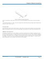
LPB2810A LPB2826A LPB2848A 10-, 26-, or 48-Port PoE+ Gigabit Managed Switch Eco Quick Start Guide An affordable managed switch with the power to be a key component of your network infrastructure. Customer Support Information LGB1108A Quick Start Guide BLACK BOX ® Order toll-free in the U.S.: Call 877-877-BBOX (outside U.S. call 724-746-5500) FREE technical support 24 hours a day, 7 days a week: Call 724-746-5500 or fax 724-746-0746 Mailing address: Black Box Corporation, 1000 Park Drive, Lawrence, PA 15055-1018 Web site: www.blackbox.com • E-mail: [email protected] Trademarks Trademarks Used in this Manual Black Box and the Double Diamond logo are registered trademarks of BB Technologies, Inc. Intel is a registered trademark of Intel Corporation Xerox is a registered trademark of Xerox Corporation. Any other trademarks mentioned in this manual are acknowledged to be the property of the trademark owners. We‘re here to help! If you have any questions about your application or our products, contact Black Box Tech Support at 724-746-5500 or go to blackbox.com and click on “Talk to Black Box.” You’ll be live with one of our technical experts in less than 30 seconds. Page 2 724-746-5500 | blackbox.com LGB1108A Quick Start Guide FCC Statement Federal Communications Commission and Industry Canada Radio Frequency Interference Statements This equipment generates, uses, and can radiate radio-frequency energy, and if not installed and used properly, that is, in strict accordance with the manufacturer’s instructions, may cause interference to radio communication. It has been tested and found to comply with the limits for a Class A computing device in accordance with the specifications in Subpart B of Part 15 of FCC rules, which are designed to provide reasonable protection against such interference when the equipment is operated in a commercial environment. Operation of this equipment in a residential area is likely to cause interference, in which case the user at his own expense will be required to take whatever measures may be necessary to correct the interference. Changes or modifications not expressly approved by the party responsible for compliance could void the user’s authority to operate the equipment. This digital apparatus does not exceed the Class A limits for radio noise emission from digital apparatus set out in the Radio Interference Regulation of Industry Canada. Le présent appareil numérique n’émet pas de bruits radioélectriques dépassant les limites applicables aux appareils numériques de la classe A prescrites dans le Règlement sur le brouillage radioélectrique publié par Industrie Canada. LGB1108A Quick Start Guide 724-746-5500 | blackbox.com Page 3 NOM Statement Instrucciones de Seguridad (Normas Oficiales Mexicanas Electrical Safety Statement) 1. Todas las instrucciones de seguridad y operación deberán ser leídas antes de que el aparato eléctrico sea operado. 2. Las instrucciones de seguridad y operación deberán ser guardadas para referencia futura. 3. Todas las advertencias en el aparato eléctrico y en sus instrucciones de operación deben ser respetadas. 4. Todas las instrucciones de operación y uso deben ser seguidas. 5. El aparato eléctrico no deberá ser usado cerca del agua—por ejemplo, cerca de la tina de baño, lavabo, sótano mojado o cerca de una alberca, etc. 6. El aparato eléctrico debe ser usado únicamente con carritos o pedestales que sean recomendados por el fabricante. 7. El aparato eléctrico debe ser montado a la pared o al techo sólo como sea recomendado por el fabricante. 8. Servicio—El usuario no debe intentar dar servicio al equipo eléctrico más allá a lo descrito en las instrucciones de operación. Todo otro servicio deberá ser referido a personal de servicio calificado. 9. El aparato eléctrico debe ser situado de tal manera que su posición no interfiera su uso. La colocación del aparato eléctrico sobre una cama, sofá, alfombra o superficie similar puede bloquea la ventilación, no se debe colocar en libreros o gabinetes que impidan el flujo de aire por los orificios de ventilación. 10. El equipo eléctrico deber ser situado fuera del alcance de fuentes de calor como radiadores, registros de calor, estufas u otros aparatos (incluyendo amplificadores) que producen calor. 11. El aparato eléctrico deberá ser connectado a una fuente de poder sólo del tipo descrito en el instructivo de operación, o como se indique en el aparato. 12. Precaución debe ser tomada de tal manera que la tierra fisica y la polarización del equipo no sea eliminada. 13. Los cables de la fuente de poder deben ser guiados de tal manera que no sean pisados ni pellizcados por objetos colocados sobre o contra ellos, poniendo particular atención a los contactos y receptáculos donde salen del aparato. 14. El equipo eléctrico debe ser limpiado únicamente de acuerdo a las recomendaciones del fabricante. 15. En caso de existir, una antena externa deberá ser localizada lejos de las lineas de energia. 16. El cable de corriente deberá ser desconectado del cuando el equipo no sea usado por un largo periodo de tiempo. 17. Cuidado debe ser tomado de tal manera que objectos liquidos no sean derramados sobre la cubierta u orificios de ventilación. 18. Servicio por personal calificado deberá ser provisto cuando: A: El cable de poder o el contacto ha sido dañado; u B: Objectos han caído o líquido ha sido derramado dentro del aparato; o C: El aparato ha sido expuesto a la lluvia; o D: El aparato parece no operar normalmente o muestra un cambio en su desempeño; o E: El aparato ha sido tirado o su cubierta ha sido dañada. Page 4 724-746-5500 | blackbox.com LGB1108A Quick Start Guide Table of Contents Table of Contents 1. Specifications..........................................................................................................................................................................6 1.1 Physical Characteristics...................................................................................................................................................6 1.2 Switch Features..............................................................................................................................................................6 1.3 Management Features....................................................................................................................................................7 1.4 Standards.......................................................................................................................................................................7 1.5 Compliances...................................................................................................................................................................7 2. Overview................................................................................................................................................................................8 2.1 Introduction....................................................................................................................................................................8 2.2 Features..........................................................................................................................................................................8 2.3 Description of Hardware................................................................................................................................................9 3. Network Planning................................................................................................................................................................. 11 3.1 Introduction to Switching............................................................................................................................................. 11 3.2 Application Examples................................................................................................................................................... 11 4. Installation............................................................................................................................................................................ 13 4.1 Selecting a Site............................................................................................................................................................. 13 4.2 Ethernet Cabling........................................................................................................................................................... 13 4.3 Equipment Checklist..................................................................................................................................................... 13 4.4 What’s Included........................................................................................................................................................... 14 4.5 Mounting Instructions.................................................................................................................................................. 14 5. Network Connections.......................................................................................................................................................... 21 5.1 Connecting Network Devices....................................................................................................................................... 21 5.2 Twisted-Pair Devices..................................................................................................................................................... 21 6. Labeling Connections...........................................................................................................................................................25 7. Troubleshooting....................................................................................................................................................................26 7.1 Common Problems.......................................................................................................................................................26 7.2 When You Turn the Unit On........................................................................................................................................27 7.3 In-band Access.............................................................................................................................................................27 8. Cabling .............................................................................................................................................................................28 9. Glossary .............................................................................................................................................................................32 LGB1108A Quick Start Guide 724-746-5500 | blackbox.com Page 5 Chapter 1: Specifications 1. Specifications 1.1 Physical Characteristics Aggregate Bandwidth — 20 Gbps Buffer Architecture — 1392 KB on-chip frame buffer Network Interface — LPB2810A: Ports 1–8: RJ-45 connector, Auto MDI-X; Ports 9–10: RJ-45 connector/(100/1000M) SFP; 10BASE-T: RJ-45 (100-ohm, UTP cable; Category 3 or better); 100BASE-TX: RJ-45 (100-ohm, UTP cable; Category 5 or better); 1000BASE-T: RJ-45 (100-ohm, UTP or STP cable; Category 5, 5e or 6); LPB2826A: Ports 1–20: RJ-45 connector, Auto MDI-X; Ports 21–24: RJ-45 connector/(100/1000M) SFP, Ports 25–26: 100/1000M SFP, 10BASE-T: RJ-45 (100-ohm, UTP cable; Category 3 or better); 100BASE-TX: RJ-45 (100-ohm, UTP cable; Category 5 or better); 1000BASE-T: RJ-45 (100-ohm, UTP or STP cable; Category 5, 5e, or 6); LPB2848A: Ports 1–44: RJ-45 connector, Auto MDI-X; Ports 45–48: RJ-45 connector/(100/1000M) SFP, 10BASE-T: RJ-45 (100-ohm, UTP cable; Category 3 or better); 100BASE-TX: RJ-45 (100-ohm, UTP cable; Category 5 or better); 1000BASE-T: RJ-45 (100-ohm, UTP or STP cable; Category 5, 5e, or 6) Ports — LPB2810A: (8) 10/100/1000 Mbps TP; (2) 100/1000 Mbps SFP Fiber/(10/100/1000 Mbps) TP dual-media ports, (1) RJ-45 console . port; LPB2826A: (20) 10/100/1000 Mbps TP, (4) 100/1000 Mbps SFP Fiber/(10/100/1000 Mbps) TP dual-media ports, (2) 10/1000M SFP ports, (1) RJ-45 console port; LPB2848A: (44) 10/100/1000 Mbps TP, (4) 100/1000 Mbps SFP Fiber/(10/100/1000 Mbps) TP dual media ports, (1) DB9 console port Switching Database — 8K MAC address entries Indicators — LEDs: System: Power; TP Port: status (LINK/ACT), 10/100/1000M; SFP Port: status (LINK/ACT/SPD), 100/1000M Temperature Tolerance — Operating: 32 to 104° F (0 to 40° C) Humidity Tolerance — Operating: 5 to 90% (non-condensing) Power — Input: 100–240 VAC, 50–60 Hz internal power supply, autosensing; Consumption: LPB2810A: 130 watts PoE (IEEE 802.3 af, IEEE 802.3at); LPB2826A, LPB2848A: 370 watts PoE (IEEE 802.3 af, IEEE 802.3at) Size — LPB2810A: 1.7"H x 11"W x 6.5"D (4.4 x 28 x 16.6 cm); LPB2826A: 1.75" (1U) H x 17.4"W x 8.3"D (4.4 x 44.2 x 21.1 cm); LPB2848A: 1.75" (1U) H x 17.4"W x 11.8"D (4.4 x 44.2 x 30 cm) Weight — LPB2810A: 2.97 lb. (1.35 kg); LPB2826A: 5.3 lb. (2.4 kg); LPB2848A: 9 lb. (4.1 kg) 1.2 Switch Features Flow Control — Full-duplex: IEEE 802.3x Half-duplex: Backpressure Forwarding Mode — Store-and-forward Throughput — 35.71 Mbps Page 6 724-746-5500 | blackbox.com LGB1108A Quick Start Guide Chapter 1: Specifications 1.3 Management Features In-Band Management — SSH/SSL, Telnet, SNMP, or HTTP Out-of-Band Management — RS-232 (RJ-45 console port) Software Loading — HTP, TFTP in-band, Console out-of-band 1.4 Standards Standards — IEEE 802.3: 10BASE-T Ethernet (twisted-pair copper), IEEE 802.3u: 100BASE-TX Ethernet (twisted-pair copper), IEEE 802.3ab: 1000BASE-TX Ethernet (twisted-pair copper), IEEE 802.3z: 1000BASE-X Ethernet, IEEE 802.3x: flow control capability, ANSI/IEEE 802.3: autonegotiation, IEEE 802.1Q: VLAN, IEEE 802.1p: Class of service, IEEE 802.1X: Access control, IEEE 802.1D: Spanning tree, IEEE 802.1w: Rapid spanning tree, IEEE 802.1s: Multiple spanning tree, IEEE 802.3ad: Link aggregation control protocol (LACP), IEEE 802.1AB: Link layer discovery protocol (LLDP) 1.5 Compliances Compliance — EN55022 (CISPR 22) Class A EN 61003 FCC Class A CE Mark Immunity — EN61000-4-2/3/4/5/6/8/11, EN 55024 LGB1108A Quick Start Guide 724-746-5500 | blackbox.com Page 7 Chapter 2: Overview 2. Overview 2.1 Introduction The 10-, 26-, or 48-Port PoE+ Gigabit Managed Switch Eco is an affordable managed switch that is a key part of a reliable infrastructure for your business network. This switch delivers the kind of intelligent features you need: • to improve the availability of your critical business applications; • to protect your sensitive information; and • to optimize your network bandwidth. Easy to set up and use, the PoE+ Gigabit Managed Switch Eco provides stable and quality performance to support all types of data, voice, security, and wireless technologies. It provides the ideal combination of affordability and capabilities for entry-level networking for small businesses or home office applications and helps create a more efficient, better-connected workforce. Switch TP LEDs Power LED Reset/ Default RJ-45 console port 10/100/1000BASE-T RJ-45 ports TP and 100/1G SFP ports Figure 2-1. Front panel of the 10-Port PoE+ Gigabit Managed Switch Eco (LPB2810A). NOTE: The 26- and 48-Port PoE+ Gigabit Managed Switch Ecoes’ front panels are similar to the 10-Port Switch. All three switches have the same Power LED and Reset/Default. The LPB2810A has (8) 10/100/1000BASE-T RJ-45 ports, (2) TP and 100/1G SFP ports, (16) switch TP LEDs, and (1) RJ-45 console port. The LPB2826A has (20) 10/100/1000BASE-T RJ-45 ports, (4) dual-media UTP/SFP ports, (2) SFP ports, (40) switch TP LEDs, and (1) RJ-45 console port. The LPB2848A has (44) 10/100/1000BASE-T RJ-45 ports, (4) dual-media UTP/SFP ports, (88) switch TP LEDs, and (1) DB9 console port. 2.2. Features • Switch Architecture: This switch performs a wire-speed, non-blocking switching fabric, which enables wire-speed transport of multiple packets at low latency on all ports simultaneously. The switch also features full-duplex capability on all ports, which effectively doubles the bandwidth of each connection. It uses store-and-forward technology to ensure maximum data integrity. With this technology, the entire packet must be received into a buffer and checked for validity before being forwarded. This prevents errors from being propagated throughout the network. • Network Management Options: The switch can also be managed over the network with a Web browser or Telnet application. The switch includes a built-in network management agent that allows it to be managed in-band using SNMP or RMON (Groups 1, 2, 3, 9) protocols. It also has an RJ-45 console port connector on the front panel for out-of-band management. A PC may be connected to this port for configuration and monitoring out-of-band via a null-modem serial cable. (For more information on cabling, see Chapter 9: Cables.) NOTE: For a detailed description of the management features, refer to the User’s Manual. Page 8 724-746-5500 | blackbox.com LGB1108A Quick Start Guide Chapter 2: Overview 2.3 Description of Hardware •1 000BASE-T Ports: The switch contains (8), (20), or (44) 1000BASE-T RJ-45 ports. All RJ-45 ports support automatic MDI/ MDI-X operation, autonegotiation, and IEEE 802.3x autonegotiation of flow control, so the optimum data rate and transmission can be selected automatically. • SFP Transceiver Slots: The LBG1108A 10-Port PoE+ Gigabit Managed Switch Eco supports the small form-factor pluggable (SFP) transceiver slots, which are shared with RJ-45 Port 9 and 10. In the default configuration, if an SFP transceiver (purchased separately) is installed in a slot and has a valid link on the port, the associated RJ-45 port is disabled. The LPB2826A 26-Port PoE+ Gigabit Managed Switch Eco also supports the small form-factor pluggable (SFP) transceiver slots, which are shared with RJ-45 Ports 21–24, and (2) additional SFP ports. The LPB2848A 48-Port PoE+ Gigabit Managed Switch Eco has (4) dual-media UTP/SFP ports (Ports 45–48). The following table shows a list of transceiver types that have been tested with the switch. For an updated list of vendors supplying these transceivers, contact your local dealer. For information on the recommended standards for fiber optic cabling, see “1000-Mbps Gigabit Ethernet Collision Domain” in Section 5.2, Tables 5-1 through 5-4, or contact Tech Support at 724-746-5500. Table 2-1: Supported SFP Transceivers. Media Standard Filter Diameter (Microns) Wavelenth (nm) Maximum Distance* 50/125 850 550 m (1804.5 ft.) 62.5/125 850 275 m (902.2 ft.) 9/125 1310 10 km (6.2 mi.) 9/125 1550 30.5 km (19.0 mi.) 9/125 1300 10 km (6.2 mi.) n/a TX-1310/RX-1550 20 km (12.4 mi.) n/a TX-1550/RX-1310 20 km (12.4 mi.) n/a n.a 100 m (328.1 ft.) 50/125 850 2 km (1.2 mi.) 62.5/125 1550 15 km (9.3 mi.) 1000BASE-SX 1000BASE-LX/LHX/XD/ZX 1000BASE-LX Single-Strand 1000BASE-T 100BASE-FX * NOTE: Maximum distance may vary for different SFP vendors. LGB1108A Quick Start Guide 724-746-5500 | blackbox.com Page 9 Chapter 2: Overview • Port and System Status LEDs: The switch includes a display panel for system and port indications that simplify installation and network troubleshooting. The LEDs are located on the left side of the front panels for easy viewing. Details are shown below and in Tables 2-2 and 2-3: Table 2-2: Port Status LEDs LED Conditions Status TP (Link/ACT) Green Lit Green when TP link is good; blinks when any traffic is present. TP Speed Green Lit Green when the TP link is on 1000 Mbps; Blinks when the TP link is on 100 Mbps; Off when the TP link is on 10 Mbps. SFP (Link/ACT) Green/Amber Lit Green when the SFP link is on 1000 Mbps; Lit Amber when the SFP link is on 100 Mbps; Blinks when any traffic is present Table 2-3: System Status LEDs LED Conditions Status Power Green Lit when power is on. • Power Supply Socket: There is a standard 120-VAC power socket on the rear panel of the switch. Figure 2-2. Back panel. Page 10 724-746-5500 | blackbox.com LGB1108A Quick Start Guide Chapter 3: Network Planning 3. Network Planning 3.1 Introduction to Switching A network switch is one of the most important devices for today’s networking technology. It enables simultaneous transmission of multiple packets, and it can partition a network more efficiently than bridges or routers. When performance bottlenecks are caused by congestion at the network access point such as a file server, devices can be connected directly to a switched port. And, by using full-duplex mode, the bandwidth of the dedicated segment can be doubled to maximize throughput. When networks are based on repeater (hub) technology, the distance between end stations is limited by a maximum hop count. However, a switch can subdivide the network into smaller and more manageable segments, linking them to the larger network than can turn the hop count back to zero, removing the limitation. A switch can be easily configured in any Ethernet, Fast Ethernet, or Gigabit Ethernet network to significantly increase bandwidth while using conventional cabling and network cards. 3.2 Application Examples The PoE+ Gigabit Managed Switch Eco uses (8), (20), or (44) Gigabit Ethernet TP ports with Auto MDI-X and two slots for the removable SFP module, which supports a number of types of fiber connections, including LC and BiDi-LC modules. It is not only designed to segment your network, but also to provide a wide range of options in setting up network connections. Some typical applications showing the 10-Port PoE+ Gigabit Managed Switch Eco (LPB2810A) are described below. NOTE: The LPB2826A and LPB2848A are similar to the LPB2810A, but have (20) or (44) Gigabit ports. The LPB2826A and LPB2848A also have dual-media SFP/(10/100/1000) ports, which are described in the specifications section of this manual. • Remote site application in enterprise or small businesses. • Peer-to-peer application when used in two remote offices. • Office network. • High-performance requirement environment. • Advanced security for network safety applications. • Data, voice, and videoconferencing applications. LPB2810A LPB2810A LPB2810A LPB2810A Figure 3-1. Network connection between remote site and central site. LGB1108A Quick Start Guide 724-746-5500 | blackbox.com Page 11 Chapter 3: Network Planning LPB2810A Figure 3-2. Peer-to-peer network connection Internet LPB2810A LPB2810A LPB2810A Figure 3-3. Office network connection Page 12 724-746-5500 | blackbox.com LGB1108A Quick Start Guide Chapter 4: Installation 4. Installation 4.1 Selecting a Site The switch can be mounted in a standard 19-inch equipment rack (via an optional rackmount kit) or on a flat surface. Be sure to follow the guidelines below when choosing a location. The site should: • Be at the center of all the devices you want to link and near a power outlet. • Be able to maintain its temperature within 32 to 104° F (0 to 40° C) and its humidity within 10 to 90%, noncondensing. • Be accessible for installing, cabling, and maintaining the devices. • Allow the status LEDs to be clearly visible. Make sure the twisted-pair Ethernet cable is always routed away from power lines, radios, transmitters, or any other electrical interference. Make sure that the 10-Port PoE+ Gigabit Managed Switch Eco is connected to a separate grounded power outlet that provides 100 to 240 VAC, 50 to 60 Hz. 4.2 Ethernet Cabling To ensure proper operation when installing the switch in a network, make sure that the current cables are suitable for 100BASE-TX or 1000BASE-T operation. Check the following criteria against the current installation of your network: • Cable type: Unshielded twisted-pair (UTP) or shielded twisted-pair (STP) cable with RJ-45 connectors; Category 5 or Category 5e with a maximum length of 100 meters (328.1 feet) is recommended for 100BASE-TX, and Category 5e or 6 with maximum length of 100 meters (328.1 feet) is recommend for 1000BASE-T. • Protection from radio-frequency interference emissions. • Electrical surge suppression. • Separation of electrical wires and data-based network wiring. • Safe connections with no damaged cables, connectors, or shields. Figure 4-1. RJ-45 connections. Figure 4-2. SFP transceiver. 4.3 Equipment Checklist After unpacking this switch, please check the contents to be sure you have received all the components. Then, before beginning the installation, be sure you have all other necessary installation equipment. LGB1108A Quick Start Guide 724-746-5500 | blackbox.com Page 13 Chapter 4: Installation 4.4 What’s Included • 10-, 26-, or 48-Port PoE+ Gigabit Managed Switch Eco (LPB2810A, LPB2826A, or LPB2848A) • AC power cord • (4) Adhesive rubber feet • RS-232 to RJ-45 console cable (for LPB2810A and LPB2826A) or DB9 to DB9 console cable (for LPB2848A) • (2) brackets • (6) screws • This quick start guide • User’s manual on CD NOTE: Call Black Box immediately if any of these items is missing or damaged. WARNING: The SFP transceivers are Class 1 Laser Devices. Avoid direct eye exposure to the beam coming from the transmit port. 4.5 Mounting Instructions The switch can be mounted in a standard 19-inch equipment rack or on a desktop or shelf. Rackmounting Before rackmounting the switch, check the following: • Temperature: Since the temperature within a rack assembly may be higher than the ambient room temperature, check that the rack environment temperature is within the specified operating temperature range of 32 to 104° F (0 to 40 ° C). • Mechanical loading: Do not place any equipment on top of a rackmounted unit. • Circuit overloading: Be sure that the supply circuit to the rack assembly is not overloaded. • Grounding: Rackmounted equipment should be properly grounded. To rackmount devices Step 1: Attach the brackets to the device using the screws provided. Figure 4-3. Attaching the brackets. Page 14 724-746-5500 | blackbox.com LGB1108A Quick Start Guide Chapter 4: Installation Step 2. Mount the switch and bracket assembly in the rack using (4) rackmounting screws (not provided). Be sure to secure the lower rackmounting screws first to prevent the brackets from being bent by the weight of the switch. Figure 4-4 Installing the switch in a rack. Step 3. If installing a single switch only, turn to “Connecting to a Power Source“ later in this chapter. Step 4. If installing multiple switches, mount them in the rack, one below the other, in any order. Desktop or Shelf Mounting Step 1: Attach the four adhesive rubber feet to the bottom of the first switch. Figure 4-5. Attaching the adhesive rubber feet. Step 2. Set the device on a flat surface near an AC power source, making sure there are at least two inches of space on all sides for proper airflow. Step 3. If installing a single switch only, go to “Connecting to a Power Source” later in this chapter. Step 4. If installing multiple switches, attach four adhesive feet to each one. Place each device squarely on top of the one below, in any order. LGB1108A Quick Start Guide 724-746-5500 | blackbox.com Page 15 Chapter 4: Installation Optional SFP Transceivers You can install or remove an SFP transceiver from an SFP slot without powering off the switch. NOTE: The SFP slots are shared with the two or four 10/100/1000BASE-T RJ-45 ports. If an SFP transceiver is installed in a slot, the associated RJ-45 port is disabled and cannot be used. The LPB2810A has (2) dual-media SFP/(10/100/1000) RJ-45 ports. The LPB2826A has (4) dual-media SFP/(10/100/11000) RJ-45 ports, plus (2) extra SFP ports. The LPB2848A has (4) dual-media SFP/ (10/100/1000) RJ-45 ports. NOTE: The SFP ports operate only at full-duplex. Half-duplex operation is not supported. NOTE: Ensure the network cable is NOT connected when you install or remove an SFP transceiver. Figure 4-6. Inserting an SFP transceiver into a slot. Table 4-1: Supported SFP Transceivers. Model Name Description 1000BASE-SX GE SFP Fiber Module, LC Multimode 850 nm 1000BASE-SX GE SFP Fiber Module, LC Multimode 1310 nm 2 km 1000BASE-LX GE SFP Fiber Module, LC Single-Mode 10 km 1000BASE-LX GE SFP Fiber Module, LC Single-Mode 30 km These models are available. Contact Tech Support for the correct SFP for your application. 1000BASE-LX GE SFP Fiber Module, LC Single-Mode 50 km 1000BASE-LX GE SFP Fiber Module, LC Single-Mode 50 km 1000BASE-LX GE SFP Fiber Module, Bidi LC Single-Mode 10 km, 1310 nm 1000BASE-LX GE SFP Fiber Module, Bidi LC Single-Mode 20 km, 1550 nm 1000BASE-LX GE SFP Fiber Module, Bidi LC Single-Mode 20 km, 1310 nm 100BASE-FX FE SFP Fiber Module, LC Multimode 2 km, 850 nm and 1310 nm 100BASE-FX FE SFP Fiber Module, LC Single-Mode 20 km, 1310 nm To Install an SFP Transceiver Step 1. Consider network and cabling requirements to select an appropriate SFP transceiver type. Step 2. Insert the transceiver with the optical connector facing outward and the slot connector facing down. Note that SFP transceivers are keyed so they can only be installed in one orientation. Step 3. Slide the SFP transceiver into the slot until it clicks into place. NOTE: SFP transceivers are not provided in the switch package. Page 16 724-746-5500 | blackbox.com LGB1108A Quick Start Guide Chapter 4: Installation Connecting to a Power Source You can plug or remove the power cord from the AC power socket to switch the power on and off . Step 1. Insert the power cable plug directly into the AC socket located at the back of the switch. Step 2. Plug the other end of the cable into a grounded, 3-pin, AC power source. Step 3. Check the front-panel LEDs as the device is powered on to be sure the POWER LED is lit. If it isn’t, check that the power cable is plugged in correctly. WARNING: For international use, you may need to change the AC power cable. You must use a power cable set that has been approved for the socket type in your country. Connecting to the Console Port The RJ-45 serial port on the switch’s front panel is used to connect to the switch for out-of-band console configuration. The command-line-driven configuration program can be accessed from a terminal or a PC running a terminal emulation program. The pin assignments used to connect to the serial port are provided in Table 4-2. Figure 4-7. Serial port (RJ-45) pinout. Wiring Map for Serial Cable Table 4-2: Serial cable pin assignments. Switch’s 8-Pin Serial Port Null Modem PC’s 9-Pin DTE Port 2 RXD (receive data) <----------------- 3 TXD (transmit data) 3 TXD (transmit data) -----------------> 2 RXD (receive data) 5 SGND (Signal ground) ------------------- 5 SGND (Signal ground) NOTE: No other pins are used. Figure 4-8. Plug in the console port. LGB1108A Quick Start Guide 724-746-5500 | blackbox.com Page 17 Chapter 4: Installation The serial port’s configuration requirements are as follows: • Default baud rate—115,200 bps • Character size—8 characters • Parity—None • Stop bit—One • Data bits—8 • Flow control—none Using Web-based Management The default values of the managed switch are listed in the table below: Table 4-3: Using Web-based Management. IP Address 192.168.1.1 Subnet Mask 255.255.255.0 Default 192.168.1.254 Username admin Password Page 18 724-746-5500 | blackbox.com LGB1108A Quick Start Guide Chapter 4: Installation After configuring the managed switch in the CLI via the switch’s serial interface, you can browse it. For instance, type “http://192.168.1.1“ [without the quotes] in the address bar in a browser, and it will show the following screen and ask you to log in. When you log in the first time, the default username is “admin”. and the password field remains blank. Figure 4-9. Web User Interface screen. NOTE: If you need to configure a function or parameter, refer to the detail in the User Guide. Or access the switch and click “help“ under the Web GUI. A help screen will provide you with help content to walk you through the process of setting the parameters. Figure 4-10. Web Help Function screen. LGB1108A Quick Start Guide 724-746-5500 | blackbox.com Page 19 Chapter 4: Installation Figure 4-11. System Information Help screen. Page 20 724-746-5500 | blackbox.com LGB1108A Quick Start Guide Chapter 5: Network Connections 5. Network Connections 5.1 Connecting Network Devices The switch is designed to be connected to 10-, 100-, or 1000-Mbps network cards in PCs and servers, as well as to other switches and hubs. It may also be connected to remote devices using optional SFP transceivers. 5.2 Twisted-Pair Devices Each device requires an unshielded twisted-pair (UTP) cable with RJ-45 connectors at both ends. Use Category 5, 5e, or 6 cable for 1000BASE-T connections; use Category 5 or better for 100BASE-TX connections. Cabling Guidelines The RJ-45 ports on the switch support automatic MDI/MDI-X pinout configuration, so you can use standard straight-through twisted-pair cables to connect to any other network device (PCs, servers, switches, routers, or hubs). For more information on cabling, see Chapter 9: Cables. CAUTION: Do not plug a phone jack connector into an RJ-45 port. This will damage the switch. Use only twisted-pair cables with RJ-45 connectors that conform to FCC standards. Connecting to PCs Servers, Hubs, and Switches Step 1: Attach one end of a twisted-pair cable segment to the device's RJ-45 connector. Step 2: If the device is a network card and the switch is in the wiring closet, attach the other end of the cable segment to a modular wall outlet that is connected to the wiring closet. (See the next section “Network Wiring Connections.”) Otherwise, attach the other end to an available port on the switch. Make sure each twisted-pair cable does not exceed 328 feet (100 m) in length. NOTE: Avoid using flow control on a port connected to a hub unless it is actually required to solve a problem. Otherwise backpressure jamming signals may degrade overall performance for the segment attached to the hub. Step 3. As each connection is made, the Link LED (on the switch) corresponding to each port will light green (1000 Mbps) or amber (100 Mbps) to indicate that the connection is valid. Network Wiring Connections Today, the punchdown block is an integral part of many of the newer equipment racks. It is actually part of the patch panel. Instructions for making connections in the wiring closet with this type of equipment follows: Step 1. Attach one end of a patch cable to an available port on the switch and the other end to the patch panel. Step 2. If not already in place, attach one end of a cable segment to the back of the patch panel where the punchdown block is located, and the other end to a modular wall outlet. Step 3. Label the cables to simplify future troubleshooting. See Chapter 6: Labeling Connections. LGB1108A Quick Start Guide 724-746-5500 | blackbox.com Page 21 Chapter 5: Network Connections Figure 5-1. Network wiring connections. Fiber Optic SFP Devices An optional Gigabit SFP transceiver can be used for a backbone connection between switches, or for connecting to a high-speed server. Each single-mode fiber port requires 9-/125- micron single-mode fiber optic cable with an LC connector at both ends. Each multimode fiber optic port requires 50-/125- or 62.5-/125-micron multimode fiber optic cabling with an LC connector at both ends. WARNING: This switch uses lasers to transmit signals over fiber optic cable. The lasers are inherently eye safe in normal operation. However, users should never look directly at a transmit port when it is powered on. Step 1. Remove and keep the LC port’s rubber plug. When not connected to a fiber cable, the rubber plug should be replaced to protect the optics. Step 2. Check that the fiber terminators are clean. You can clean the cable plugs by wiping them gently with a clean tissue or cotton ball moistened with a little ethanol. Dirty fiber terminators on fiber optic cables will impair the quality of the light transmitted through the cable and lead to degraded performance on the port. Step 3. Connect one end of the cable to the LC port on the switch and the other end to the LC port on the other device. Since LC connectors are keyed, the cable can be attached in only one orientation. Page 22 724-746-5500 | blackbox.com LGB1108A Quick Start Guide Chapter 5: Network Connections Figure 5-2. Making the fiber port connections. Step 4. As a connection is made, check the Link LED on the switch corresponding to the port to be sure that the connection is valid. The fiber optic ports operate at 1 Gbps. The maximum length for fiber optic cable operating at Gigabit speed will depend on the fiber type as listed in Tables 5-2 to 5-4. Connectivity Rules When adding hubs to your network, note that because switches break up the path for connected devices into separate collision domains, you should not include the switch or connected cabling in your calculations for cascade length involving other devices. 1000BASE-T Cable Requirements All Category 5 UTP cables that are used for 100BASE-TX connections should also work for 1000BASE-T, providing that all four wire pairs are connected. However, it is recommended that for all critical connections, or any new cable installations, Category 5e or Category 6 cable should be used. The Category 5e and 6 specifications include test parameters that are only recommendations for Category 5. Therefore, the first step in preparing existing Category 5 cabling for running 1000BASE-T is a simple test of the cable installation to be sure that it complies with the IEEE 802.3-2005 standards. LGB1108A Quick Start Guide 724-746-5500 | blackbox.com Page 23 Chapter 5: Network Connections 1000-Mbps Gigabit Ethernet Collision Domain Table 5-1: Maximum 1000BASE-T Gigabit Ethernet cable length. Cable Type Maximum Cable Length Connector Category 5, 5e, or 6 100-ohm UTP or STP 100 m (328 ft.) RJ-45 Table 5-2: Maximum 1000BASE-SX Gigabit fiber cable lengths. Fiber Size 62.5/125 micron multimode 50/125 micron multimode Fiber Bandwidth Maximum Cable Length Connector 160 MHz/km 220 m (722 ft.) LC 200 MHz/km 275 m (902 ft.) LC 400 MHz/km 500 m (1641 ft.) LC 500 MHz/km 550 m (1805 ft.) LC Table 5-3: Maximum 1000BASE-LX/LHX/XD/ZX Gigabit fiber cable lengths. Fiber Size Fiber Bandwidth Maximum Cable Length Connector 9/125 micron single-mode fiber 1310 nm n/a 10 km (6.2 miles) LC 9/125 micron single-mode fiber 1550 nm n/a 30 km (18.6 miles) LC 50 km (31.1 miles) LC Table 5-4: Maximum 1000BASE-SX Gigabit fiber cable lengths. Fiber Size Fiber Bandwidth Maximum Cable Length Connector Single-mode TX-1310 nm RX-1550 nm n/a 20 km (12.4 miles) BIDI Single-mode RX-1310 nm TX-1550 nm n/a LC 20 km (12.4 miles) BIDI LC 100-Mbps Fast Ethernet Collision Domain Table 5-5: Maximum Fast Ethernet cable length. Page 24 Cable Type Maximum Cable Length Connector Category 5, 5e, or 6 100-ohm UTP or STP 100 m (328 ft.) RJ-45 724-746-5500 | blackbox.com LGB1108A Quick Start Guide LPB2810A Chapter 6: Labeling Connections 6. Labeling Connections When planning a network installation, it is essential to label the opposing ends of cables and to record where each cable is connected. This will enable users to easily locate interconnected devices, isolate faults, and change your topology without wasting time. To best manage the physical implementations of your network, follow these guidelines: • Clearly label the opposing ends of each cable. • Using your building’s floor plans, draw a map of the location of all network-connected equipment. For each piece of equipment, identify the devices to which it is connected. • Note the length of each cable and the maximum cable length supported by the switch ports. • To make your labels easy to understand, use a location-based key when assigning prefixes to your cable labeling. • Use sequential numbers for cables that originate from the same equipment. • Differentiate between racks by naming them accordingly. • Label each separate piece of equipment. • Display a copy of your equipment map, including keys to all abbreviations at each equipment rack. LGB1108A Quick Start Guide 724-746-5500 | blackbox.com Page 25 Chapter 7: Troubleshooting 7. Troubleshooting 7.1 Common Problems Most problems are caused by the following situations. Check for these items first when starting your troubleshooting: Connecting to Devices That Have a Fixed Full-Duplex Configuration The RJ-45 ports are configured as “Auto.” That is, when connecting to attached devices, the switch will operate in one of two ways to determine the link speed and the communication mode (half-duplex or full-duplex): • If the connected device is also configured to Auto, the switch will automatically negotiate both link speed and communication mode. • If the connected device has a fixed configuration, for example 100 Mbps, at half- or full-duplex, the switch will automatically sense the link speed, but will default to a communication mode of half-duplex. Because the 10-, 26-, or 48-Port PoE+ Gigabit Managed Switch Eco behaves in this way (in compliance with the IEEE 802.3 standard), if a device connected to the switch has a fixed configuration at full-duplex, the device will not connect correctly to the switch. The result will be high error rates and very inefficient communications between the switch and the device. Make sure all devices connected to the 10-, 26-, or 48-Port PoE+ Gigabit Managed Switch Eco are configured to auto negotiate, or are configured to connect at half-duplex (all hubs are configured this way, for example). Faulty or Loose Cables Look for loose or obviously faulty connections. If that does not correct the problem, try a different cable. Non-Standard Cables Non-standard and miswired cables may cause network collisions and other network problems, and can seriously impair network performance. Use a new, correctly wired cable. For pinouts and correct cable wiring, a CATx cable tester is a recommended tool for every 100BASE-TX and 1000BASE-T network installation. Improper Network Topologies It is important to make sure you have a valid network topology. If you no longer experience the problems after reverting to your old topology, the new topology is probably at fault. In addition, you should make sure that your network topology contains no data path loops. Check the Port Configuration A port on your switch may not be operating as you expect because it has been put into a “blocking” state by Spanning Tree, GVRP (automatic VLANs), or LACP (automatic trunking). (Note that the normal operation of the Spanning Tree, GVRP, and LACP features may put the port in a blocking state.) Or, the port just may have been configured as disabled through software. Page 26 724-746-5500 | blackbox.com LGB1108A Quick Start Guide Chapter 7: Troubleshooting Table 7-1: Troubleshooting chart. Symptom Action Check connections between the switch, the power cord, and the wall outlet. Power LED is off Contact Black Box. Verify that the switch and attached device are powered on. Be sure the cable is plugged into the switch and corresponding device. Link LED is off If the switch is installed in a rack, check the connections to the punchdown block and patch panel. Verify that the proper cable type is used and that its length does not exceed specified limits. Check the adapter on the attached device and cable connections for possible defects. Replace the defective adapter or cable if necessary. 7.2 When You Turn the Unit On If the power indicator does not turn on when the power cord is plugged in, you may have a problem with the power outlet, power cord, or internal power supply. However, if the unit powers off after running for a while, check for loose power connections, power losses, or surges at the power outlet. If you still cannot isolate the problem, the internal power supply may be defective. Verify that all system components have been properly installed. If one or more components appear to be malfunctioning (such as the power cord or network cabling), test them in an alternate environment where you are sure that all the other components are functioning properly. 7.3 In-band Access You can access the management agent in the switch from anywhere within the attached network using Telnet or a Web browser. However, you must first configure the switch with a valid IP address, subnet mask, and default gateway. If you have trouble establishing a link to the management agent, check to see if you have a valid network connection. Then verify that you entered the correct IP address. Also, be sure the port through which you are connecting to the switch has not been disabled. If it has not been disabled, then check the network cabling that runs between your remote location and the switch. NOTE: The management agent accepts up to four simultaneous Telnet sessions. If the maximum number of sessions already exists, an additional Telnet connection will not be able to log into the system. LGB1108A Quick Start Guide 724-746-5500 | blackbox.com Page 27 Chapter 8: Cabling 8. Cabling For 10BASE-T and 100BASE-TX connections, the twisted-pair cable must have two pairs of wires. For 1000BASE-T connections, the twisted-pair cable must have four pairs of wires. Each wire pair is identified by two different colors. For example, one wire might be green and the other, green with white stripes. Also, an RJ-45 connector must be attached to both ends of the cable. CAUTION: DO NOT plug a phone jack connector into any RJ-45 port. Use only twisted-pair cables with RJ-45 connectors that conform with FCC standards. CAUTION: Each wire pair must be attached to the RJ-45 connectors in a specific orientation. The figure below illustrates how the pins on the RJ-45 connector are numbered. Be sure to hold the connectors in the same orientation when attaching the wires to the pins. Figure 8-1. RJ-45 connector pin numbers. 10BASE-T/100BASE-TX Pin Assignments Use unshielded twisted-pair (UTP) or shielded twisted-pair (STP) cable for RJ-45 connections: 100-ohm Category 3 or better cable for 10-Mbps connections, or 100-ohm Category 5 or better cable for 100-Mbps connections. Also be sure that the length of any twisted-pair connection does not exceed 100 meters (328 feet). The RJ-45 ports on the switch base unit support automatic MDI/MDI-X operation, so you can use straight-through cables for all network connections to PCs or servers, or to other switches or hubs. In straight-through cable, Pins 1, 2, 3, and 6, at one end of the cable, are connected straight through to Pins 1, 2, 3, and 6 at the other end of the cable. When using any RJ-45 port on this switch, you can use either straight-through or crossover cable. Table 8-1: 10BASE-T and 100BASE-TX MDI and MDI-X Port Pinouts Pin MDI Signal Name MDI-X Signal Name 1 Transmit Data plus (TD+) Receive Data plus (RD+) 2 Transmit Data minus (TD-) Receive Data minus (RD-) 3 Receive Data plus (RD+) Transmit Data plus (TD+) 6 Receive Data minus (RD-) Transmit Data minus (TD-) 4, 5, 7, 8 Not used Not used NOTE: The “+” and “-” signs represent the polarity of the wires that make up each wire pair. Page 28 724-746-5500 | blackbox.com LGB1108A Quick Start Guide Chapter 8: Cabling Straight-Through Wiring If the twisted-pair cable is to join two ports, and only one of the ports has an internal crossover (MDI-X), the two pairs of wires must be straight-through. (When auto-negotiation is enabled for any RJ-45 port on this switch, you can use either straightthrough or crossover cable to connect to any device type.) You must connect all four wire pairs as shown in the following diagram to support Gigabit Ethernet. Figure 8-2. Straight-through wiring: EIA/TIA 586B RJ-45 wiring standard 10BASE-TX / 100BASE-T straight-through cable. Crossover Wiring If the twisted-pair cable is to join two ports and either both ports are labeled with an “X” (MDI-X) or neither port is labeled with an “X” (MDI), a crossover must be implemented in the wiring unless autonegotiation is enabled. (When autonegotiation is enabled for any RJ-45 port on this switch, you can use either straight-through or crossover cable to connect to any device type.) You must connect all four wire pairs as shown in the following diagram to support Gigabit Ethernet. Figure 8-3. Crossover wiring: EIA/TIA 586B RJ-45 wiring standard 10BASE-TX / 100BASE-T crossover cable. 1000BASE-T Pin Assignments All 1000BASE-T ports support automatic MDI/MDI-X operation, so you can use straight-through cables for all network connections to PCs or servers, or to other switches or hubs. Table 8-2 shows the 1000BASE-T MDI and MDI-X port pinouts. These ports require that all four pairs of wires be connected. Note that for 1000BASE-T operation, all four pairs of wires are used for both transmit and receive. Use 100-ohm Category 5, 5e, or 6 unshielded twisted-pair (UTP) or shielded twisted-pair (STP) cable for 1000BASE-T connections. Also be sure that the length of any twisted-pair connection does not exceed 100 meters (328 ft.). LGB1108A Quick Start Guide 724-746-5500 | blackbox.com Page 29 Chapter 8: Cabling Table 8-2: 1000BASE-T MDI and MDI-X Port Pinouts Pin MDI Signal Name MDI-X Signal Name 1 Bidirectional Pair A Plus (BI_DA+) Bidirectional Pair B Plus (BI_DB+) 2 Bidirectional Pair A Minus (BI_DA-) Bidirectional Pair B Minus (BI_DB-) 3 Bidirectional Pair B Plus (BI_DB+) Bidirectional Pair A Plus (BI_DA+) 4 Bidirectional Pair C Plus (BI_DC+) Bidirectional Pair D Plus (BI_DD+) 5 Bidirectional Pair C Minus (BI_DC-) Bidirectional Pair D Minus (BI_DD-) 6 Bidirectional Pair B Minus (BI_DB-) Bidirectional Pair A Minus (BI_DA-) 7 Bidirectional Pair D Plus (BI_DD+) Bidirectional Pair C Plus (BI_DC+) 8 Bidirectional Pair D Minus (BI_DD-) Bidirectional Pair C Minus (BI_DC-) Cable Testing for Existing Category 5 Cable Installed Category 5 cabling must pass tests for Attenuation, Near-End Crosstalk (NEXT), and Far-End Crosstalk (FEXT). This cable testing information is specified in the ANSI/TIA/EIA-TSB-67 standard. Additionally, cables must also pass test parameters for Return Loss and Equal-Level Far-End Crosstalk (ELFEXT). These tests are specified in the ANSI/TIA/EIA-TSB-95 Bulletin, “The Additional Transmission Performance Guidelines for 100-Ohm 4-Pair Category 5 Cabling.” NOTE: When testing your cable installation, be sure to include all patch cables between switches and end devices. Adjusting Existing Category 5 Cabling to Run 1000BASE-T If your existing Category 5 installation does not meet one of the test parameters for 1000BASE-T, there are basically three measures that can be applied to try to correct the problem: 1. Replace any Category 5 patch cables with high-performance Category 5e or Category 6 cables. 2. Reduce the number of connectors used in the link. 3. Reconnect some of the connectors in the link. Page 30 724-746-5500 | blackbox.com LGB1108A Quick Start Guide Chapter 8: Cabling Fiber Standards The International Telecommunication Union (ITU-T) has standardized various fiber types for data networks. These are summarized in the following table: Table 8-3: Fiber standards. ITU-T Standard Description Application G.651 Multimode fiber 50/125-micron core Short-reach connections in the 1300- nm or 850-nm band. G.652 Non-dispersion-shifted fiber single-mode, 9/125-micron core Longer spans and extended reach. Optimized for operation in the 1310-nm band. but can also be used in the 1550-nm band. G.652.C Low water peak non-dispersion-shifted fiber single-mode, 9/125-micron core Longer spans and extended reach. Optimized for wavelength-division multiplexing (WDM) transmission across wavelengths from 1285 to 1625 nm. The zero dispersion wavelength is in the 1310-nm region. G.653 Dispersion-shifted fiber single-mode, 9/125-micron core Longer spans and extended reach. Optimized for operation in the region from 1500 to 1600 nm. G.654 1550-nm loss-minimized fiber single-mode, 9/125-micron core Extended long-haul applications. Optimized for highpower transmission in the 1500- to 1600-nm region, with low loss in the 1550-nm band. G.655 Non-zero dispersion-shifted fiber single-mode, 9/125-micron core Extended long-haul applications. Optimized for highpower dense wavelength-division multiplexing (DWDM) operation in the region from 1500 to 1600 nm. LGB1108A Quick Start Guide 724-746-5500 | blackbox.com Page 31 Chapter 9: Glossary 9. Glossary 10BASE-T: IEEE 802.3 specification for 10-Mbps Ethernet over two pairs of Category 3, 4, or 5 UTP cable. 100BASE-TX: IEEE 802.3u specification for 100-Mbps Ethernet over two pairs of Category 5 UTP cable. 1000BASE-LH: Specification for long-haul Gigabit Ethernet over two strands of 9-/125-micron core fiber cable. 1000BASE-LX: IEEE 802.3z specification for Gigabit Ethernet over two strands of 50-/125-, 62.5-/125-, or 9-/125-micron core fiber cable. 1000BASE-SX: IEEE 802.3z specification for Gigabit Ethernet over two strands of 50-/125- or 62.5-/125-micron core fiber cable. 1000BASE-T: IEEE 802.3ab specification for Gigabit Ethernet over 100-ohm Category 5, 5e, or 6 twisted-pair cable (using all four wire pairs). Autonegotiation: Signaling method allowing each node to select its optimum operational mode (e.g., speed and duplex mode) based on the capabilities of the node to which it is connected. Bandwidth: The difference between the highest and lowest frequencies available for network signals. Also synonymous with wire speed, the actual speed of the data transmission along the cable. Collision Domain: Single CSMA/CD LAN segment. CSMA/CD: (Carrier Sense Multiple Access/Collision Detect) is the communication method used by Ethernet, Fast Ethernet, and Gigabit Ethernet. End Station: A workstation, server, or other device that does not forward traffic. Ethernet: A network communication system developed and standardized by DEC, Intel®, and Xerox®, using baseband transmission, CSMA/CD access, logical bus topology, and coaxial cable. The successor IEEE 802.3 standard provides for integration into the OSI model and extends the physical layer and media with repeaters and implementations that operate on fiber, Thin coax, and twisted-pair cable. Fast Ethernet: A 100-Mbps network communication system based on Ethernet and the CSMA/ CD access method. Full-Duplex: Transmission method that allows two network devices to transmit and receive concurrently, effectively doubling the bandwidth of that link. Gigabit Ethernet: A 1000-Mbps network communication system based on Ethernet and the CSMA/ CD access method. IEEE: Institute of Electrical and Electronic Engineers. IEEE 802.3: Defines carrier sense multiple access with collision detection (CSMA/CD) access method and physical layer specifications. IEEE 802.3AB: Defines CSMA/CD access method and physical layer specifications for 1000BASE-T Gigabit Ethernet. (Now incorporated in IEEE 802.3-2005.) IEEE 802.3U: Defines CSMA/CD access method and physical layer specifications for 100BASE-TX Fast Ethernet. (Now incorporated in IEEE 802.3-2005.) IEEE 802.3X: Defines Ethernet frame start/stop requests and timers used for flow control on full-duplex links. (Now incorporated in IEEE 802.3-2005.) IEEE 802.3Z: Defines CSMA/CD access method and physical layer specifications for 1000BASE Gigabit Ethernet. (Now incorporated in IEEE 802.3-2005.) LAN Segment: Separate LAN or collision domain. LED: Light-emitting diode used for monitoring a device or network condition. Page 32 724-746-5500 | blackbox.com LGB1108A Quick Start Guide Chapter 9: Glossary Local Area Network (LAN): A group of interconnected computer and support devices. Media Access Control (MAC): A portion of the networking protocol that governs access to the transmission medium, facilitating the exchange of data between network nodes. MIB: An acronym for Management Information Base. It is a set of database objects that contains information about the device. Modal Bandwidth: Bandwidth for multimode fiber is referred to as modal bandwidth because it varies with the modal field (or core diameter) of the fiber. Modal bandwidth is specified in units of MHz per km, which indicates the amount of bandwidth supported by the fiber for a one-kilometer distance. Network Diameter: Wire distance between two end stations in the same collision domain. RJ-45 Connector: A connector for twisted-pair wiring. Switched Ports: Ports that are on separate collision domains or LAN segments. TIA: Telecommunications Industry Association. Transmission Control Protocol/Internet Protocol (TCP/IP): Protocol suite that includes TCP as the primary transport protocol, and IP as the network layer protocol. User Datagram Protocol (UDP): UDP provides a datagram mode for the packet-switched communications. It uses the IP as the underlying transport mechanism to provide access to IP-like services. UDP packets are delivered just like IP packets—connectionless data grams that may be discarded before reaching their targets. UDP is useful when TCP would be too complex, too slow, or unnecessary. UTP: Unshielded twisted-pair cable. Virtual LAN (VLAN): A Virtual LAN is a collection of network nodes that share the same collision domain regardless of their physical location or connection point in the network. A VLAN serves as a logical workgroup with no physical barriers, allowing users to share information and resources as though located on the same LAN. LGB1108A Quick Start Guide 724-746-5500 | blackbox.com Page 33 NOTES Page 34 724-746-5500 | blackbox.com LGB1108A Quick Start Guide NOTES LGB1108A Quick Start Guide 724-746-5500 | blackbox.com Page 35 Black Box Tech Support: FREE! Live. 24/7. Tech support the way it should be. Great tech support is just 30 seconds away at 724-746-5500 or blackbox.com. About Black Box Black Box provides an extensive range of networking and infrastructure products. You’ll find everything from cabinets and racks and power and surge protection products to media converters and Ethernet switches all supported by free, live 24/7 Tech Support available in 30 seconds or less. © Copyright 2012. Black Box Corporation. All rights reserved. LPB2810A Quick Start Guide, Rev 1 724-746-5500 | blackbox.com LGB1108A Quick Start Guide