1
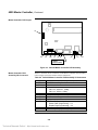
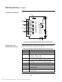
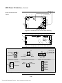
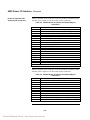
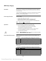
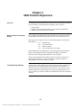
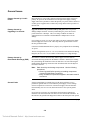
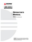
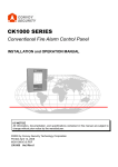
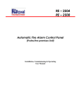
4020 Fire Alarm System System Troubleshooting Guide 574-771 Rev. A Technical Manuals Online! - http://www.tech-man.com Copyright and Trademarks Copyright 1998 Simplex Time Recorder Co. All rights reserved. Printed in the United States of America. Information in this document is subject to change without notice. No part of this document may be reproduced or transmitted in any form or by any means, electronic or mechanical, for any purpose, without the express written consent of Simplex Time Recorder Company. Cautions and Warnings SYSTEM REACCEPTANCE TEST AFTER SOFTWARE CHANGES - To ensure proper system operation, this product must be tested in accordance with NFPA72-1996, Chapter 7 after any programming operation or change in sitespecific software. Reacceptance testing is required after any change, addition or deletion of system components, or after any modification, repair or adjustment to system hardware or wiring. All components, circuits, system operations, or software functions known to be affected by a change must be 100% tested. In addition, to ensure that other operations are not inadvertently affected, at least 10% of initiating devices that are not directly affected by the change, up to a maximum of 50 devices, must also be tested and proper system operation verified. DO NOT INSTALL ANY SIMPLEX PRODUCT THAT APPEARS DAMAGED. Upon unpacking your Simplex product, inspect the contents of the carton for shipping damage. If damage is apparent, immediately file a claim with the carrier and notify Simplex. ELECTRICAL HAZARD - Disconnect electrical power when making any internal adjustments or repairs. Servicing should be performed by qualified Simplex Representatives. STATIC HAZARD - Static electricity can damage components. Therefore, handle as follows: 1. Ground yourself before opening or installing components (use the 553-484 Static Control Kit). 2. Keep uninstalled components wrapped in anti-static material at all times. RADIO FREQUENCY ENERGY - This equipment generates, uses, and can radiate radio frequency energy and if not installed and used in accordance with the instruction manual, may cause interference to radio communications. It has been tested and found to comply with the limits for a Class A computing device pursuant to Subpart J of Part 15 of FCC Rules, which are designed to provide reasonable protection against such interference when operated in a commercial environment. Operation of this equipment in a residential area is likely to cause interference in which case the user at his own expense will be required to take whatever measures may be required to correct the interference. Technical Manuals Online! - http://www.tech-man.com Table of Contents Tables and Figures In this Document................................................... ii Chapter 1 About This Document Introduction ....................................................................................... 1-1 Chapter Content................................................................................. 1-1 Chapter 2 Basic System / Sub-Assembly General Description........................................................................ 2-1 Master Controller Assembly ........................................................... 2-1 Standard Slave Card Assembly ..................................................... 2-1 Expansion Cards ............................................................................ 2-2 Addressing...................................................................................... 2-2 4020 Master Controller....................................................................... 2-3 Description and Functions.............................................................. 2-3 System Block Diagram (Universal Supply) .................................... 2-4 System Block Diagram (Intelligent Supply) .................................... 2-5 Master Controller PCB Layout........................................................ 2-6 Master Controller PCB Assembly I/O Connectors ......................... 2-6 4020 Standard Slave.......................................................................... 2-7 Description and Functions.............................................................. 2-7 Application ...................................................................................... 2-7 Standard Slave PCB Layout........................................................... 2-8 Standard Slave PCB Assembly I/O Connectors ............................ 2-8 4020 Power I/O Interface ................................................................... 2-9 Description and Functions.............................................................. 2-9 Application ...................................................................................... 2-9 Power I/O Interface PCB Layout .................................................. 2-10 Power I/O Connector Voltage Points............................................ 2-10 Power I/O Interface PCB Assembly I/O Connectors .................... 2-11 4020 Power Supply .......................................................................... 2-12 Description and Functions............................................................ 2-12 Application .................................................................................... 2-12 Power Supply I/O Connectors ...................................................... 2-12 Chapter 3 4020 Problem Experience Overview......................................................................................... 3-1 Where Problems are likely to Reside ............................................. 3-1 Troubleshooting Difficulty ............................................................... 3-1 General Issues ................................................................................... 3-2 Problems Associated with Assembly/Dis-Assembly and Installation. 3-4 Problems Associated with Power Supplies........................................ 3-6 Chapter 4 Troubleshooting Procedures General Approach .......................................................................... 4-1 Matching Standard Slave, Power Supply and Software Versions . 4-1 Master Controller Initialization ........................................................ 4-3 +5V Power ...................................................................................... 4-3 Panel Alarm Sounding and can not be Silenced............................ 4-4 A-tap Problems............................................................................... 4-4 B-tap Problems............................................................................... 4-5 +28V Power .................................................................................... 4-5 Standard Slave Initialization ........................................................... 4-5 36V Mapnet Power ......................................................................... 4-6 Troubleshooting Chart.................................................................... 4-7 Chapter 5 Standard Slave Software Initialization Standard Slave Initialization Sequence.......................................... 5-1 i Technical Manuals Online! - http://www.tech-man.com Tables and Figures in this Document Tables Figures Table Description Page Table 2-1 4020 System Device Address Assignments 2-2 Table 2-2 565-325 Master Controller PCB Assembly I/O Connectors 2-5 Table 2-3 Jumper Plug Color Code Scheme 2-7 Table 2-4 565-222 & 565-368 Standard Slave PCB Assembly I/O Connectors 2-8 Table 2-5 565-256 Power I/O Interface PCB Assembly I/O Connectors 2-11 Table 2-6 565-220 Power I/O Interface PCB Assembly I/O Connectors 2-11 Table 2-7 636-341 (Gold Wing) Power Supply I/O Connectors 2-12 Table 2-8 636-289 (Black Hawk) Power Supply I/O Connectors 2-12 Table 4-1 Troubleshooting Chart 4-7 Table 5-1 Standard Slave Initialization Sequence 5-1 Figure Description Page Figure 2-1 4020 System Block Diagram (Universal Supply Installation) 2-4 Figure 2-2 4020 System Block Diagram (Intelligent Supply Installation) 2-5 Figure 2-3 565-325 Master Controller PCB Assembly 2-6 Figure 2-4 565-222 & 565-368 Standard Slave PCB Assembly 2-8 Figure 2-5 565-256 Power I/O Interface PCB Assembly 2-10 Figure 2-6 565-220 Power I/O Interface PCB Assembly 2-10 Figure 2-7 Voltage Points on Power I/O PCB Connectors and Terminal Blocks 2-10 ii Technical Manuals Online! - http://www.tech-man.com Chapter 1 About This Document Introduction This troubleshooting guide provides you with a basic understanding of the 4020 Fire Alarm Control Panel operation and suggestions for quickly finding and resolving problems. The primary goal is to provide a method by which you may troubleshoot the 4020 basic system assemblies: • • • • Master Controller Standard Slave Power I/O Interface Power Supply It is assumed that any defective system can be broken down into this minimum configuration as the first step in troubleshooting a problem. Chapter Content This document is divided into five Chapters: 1. About this Document Describes this document’s structure. 2. Basic System/Sub-Assembly Describes the 4020 system. Includes Block Diagrams, and PCB layouts. 3. 4020 Problem Experience Describes commonly occurring problems based on Service repair experience. 4. Troubleshooting Procedures Provides problem indications with their associated potential causes. Includes a Troubleshooting Chart (page 4-7) 5. Standard Slave Software Initialization Describes the sequence of events during the Standard Slave Card initialization process. 1-1 Technical Manuals Online! - http://www.tech-man.com Chapter 2 Basic System / Sub-Assembly General Description The basic 4020 Fire Alarm Control Panel is comprised of four assemblies: • Master Controller • Standard Slave (Part No. 565-325) (Part No. 565-368 for Universal Supply installation 565-222 for Intelligent Supply installation) • Power I/O Interface (Part No. 565-256 for Universal Supply installation 565-220 for Intelligent Supply installation) • Power Supply (Part No. 636-341 for Universal Supply installation 636-289 for Intelligent Supply installation) Master Controller The Master Controller PCB assembly is responsible for overall 4020 system supervision and control. The Master Controller communicates with other system sub-assemblies over a two-wire RUI signal interface. Certain interactions between the Standard Slave and Power I/O Interface boards are necessary so that system power can be properly initialized. Once this initialization occurs, the Master Controller to can perform supervisory functions: • With +5V power initialized, the Master Controller can supervise the panel keypad and display operation status. • With +28V power, the Master Controller can use its communications interface to supervise system status and control signal circuits in the event of an alarm condition. The status of Monitor, NAC, Mapnet and Power Supply circuits is polled and reported back to the Master Controller upon demand. The Master Controller evaluates Slave card information and initiates signaling devices when an alarm condition is detected. Standard Slave Card The basic system Standard Slave card controls power supply initialization. It then supervises and controls I/O circuits at the command of the Master Controller. The Standard Slave also supervises a Mapnet channel. On power-up each microprocessor initializes independently. There are several possible problems that can interrupt the Standard Slave cards initialization process and cause the system to hang. For details of the Standard Slave initialization process refer to Chapter 5; “Standard Slave Software Initialization”. Continued on next page 2-1 Technical Manuals Online! - http://www.tech-man.com Basic System/Sub-Assembly, Continued Expansion The basic 4020 Fire Alarm Control Panel is capable of supporting system expansion with peripheral cards. Although not discussed further in this troubleshooting document, the following list shows some of the supported expansion cards: • • • • • • Addressing RS-232 Interface (Part No. 565-430) [supercedes 565-224] Optional Mapnet Transceiver Interface (Part No. 565-241) 8 Point I/O (Part No.565-211) Contact Closure DACT (Part No. 565-627) Serial DACT (Part No. 565-629) Multiple Network Option Boards (Part Nos. 565-277, 565-411, 565-518) Most PCB assemblies in the system are assigned addresses for communication with the Master Controller. The Standard Slave Card SW1 address switch is set to device address 01, but the card also responds to Power Supply address 02 and Mapnet Channel #1 address 03. The pre-designated 4020 System device address assignments are listed in Table 2-1. Table 2-1. 4020 System Device Address Assignments Address System Device 0 Master Controller 1 Standard Slave (board address setting) 2 Power Supply (software address only) 3 Mapnet Channel #1 (software address only) 4 Optional Mapnet Channel #2 5 Optional 8 Point I/O #2 6 Optional 8 Point I/O #3 7 Optional RS232 Board 8 Optional Network Board 9 Optional 4003 Voice Controller 10 Optional Mapnet Channel #3 (Master Controller OS U9 Rev 7.03 and up) 11 Optional Mapnet Channel #4 (Master Controller OS u9 Rev 7.03 and up) 12 Open 13 and Up Additional Options (SDACT, RCU, SCU, LCD, etc.) 2-2 Technical Manuals Online! - http://www.tech-man.com 4020 Master Controller Description The Master Controller PCB assembly supervises panel operations and controls the front panel user interface. The Master Controller communicates with panel PCB subassemblies via a +28V signal level communications interface. Peripheral PCB assemblies are optically coupled to this communications interface. Based upon the information in the configuration flash chip (U8) the Master Controller communicates with peripheral interface cards and directs system monitor point supervision and signal circuit control. The Master Controller +5V and +28V A-tap power originates on the Power I/O Interface and is daisy chained through the Standard Slave card. Master Controller Functions The Master Controller: • • • • • • Includes main 80196 microprocessor and memory Processes data from all other 4020 sub-assemblies Controls operator keyboard, piezo alarm and display interface Provides a programmer interface for downloading configuration changes Includes city circuit interface and contains a dry contact trouble circuit Contains communications circuitry to Slave cards and LCD Annunciators Continued on next page 2-3 Technical Manuals Online! - http://www.tech-man.com 4020 Master Controller, Continued System Block Diagram (Universal Supply) KEYPAD/LEDs P1 LCD DISPLAY P8 MASTER CONTROLLER (565-325) P3 TB1 TO PROGRAMMER CABLE CITY, TBL, RUI COMM P2 COMM / POWER (+28, +5, 0V) P6 P7 TB1 I/O #1 I/O #2 TB2 I/O #3 TB3 STANDARD SLAVE (565-368) TB4 I/O #4 TB5 COMM / POWER TO OPTIONS MAPNET P8 +36V, 0V P5 +5V, +28V, 0V P9 STATUS / CONTROL J1 OPTION INTERFACE TB1 A TAP TB2 B TAP TB3 C TAP TB4 P4 POWER I/O INTERFACE (565-256) P9 P2 P3 +36V TO OPTION BOARD P1 +PMSI LOOP PLUG H1 – H3 +28V / 0V / CHARGER STATUS & CONTROL / +28 UPS (RED / BLK / YEL) P2 BATTERY HARNESS POWER SUPPLY (636-341) TB1 AC POWER Figure 2-1. 4020 System Block Diagram (Universal Supply Installation) 2-4 Technical Manuals Online! - http://www.tech-man.com 4020 Master Controller, Continued System Block Diagram (Intelligent Supply) KEYPAD/LEDs P1 LCD DISPLAY P8 MASTER CONTROLLER (565-325) P3 TO PROGRAMMER CABLE TB1 CITY, TBL, RUI COMM P2 COMM / POWER (+28, +5, 0V) P6 P7 TB1 I/O #1 I/O #2 TB2 I/O #3 TB3 STANDARD SLAVE (565-222) TB4 I/O #4 COMM / POWER TO OPTIONS TB5 MAPNET P8 +36V, 0V P5 +5V, +28V, 0V P9 STATUS / CONTROL P1 P2 POWER I/O INTERFACE (565-220) P8 P9 +36V TO OPTION BOARD TB1 A & B TAPS P7 P5 J1 SUPPLY CONTROL & MONITOR AC MONITOR / +24 UPS J1 BATTERY HARNESS AC POWER J2 J3 POWER SUPPLY (636-289) A TAP P5 P7 B TAP Figure 2-2. 4020 System Block Diagram (Intelligent Supply Installation) 2-5 Technical Manuals Online! - http://www.tech-man.com 4020 Master Controller, Continued Master Controller PCB Layout P1 P2 P4 TB1 P3 P6 P5 JW2 JW1 SW1 P7 U8 CFIG (Note Orientation) Figure 2-3. 565-325 Master Controller PCB Assembly Master Controller PCB Assembly I/O Connectors Table 2-2 describes the I/O connectors on the Master Controller PCB Assembly (refer to Figure 2-2 for the location of these connectors). Table 2-2. 565-325 Master Controller PCB Assembly I/O Connectors Label TB1 SW1 JW1 – JW2 P1 P2 P3 P4 P5 P6 P7 Description External Comm, City Circuit, Trouble Circuit Reset Switch Selects U18 size • JW1-OUT, JW2-OUT: 2 Meg • JW1-OUT, JW2-IN: 4 Meg Keypad connector Power / Comm Connector to Slave CFIG Download Programmer Port City Circuit Jumpers CFIG Flash Programming Jumper • Enable Flash Programming – 1-2 • Disable Flash Programming – 2-3 Carrier Detect TXD Enable (1-2 Normal, 2-3 Modem) RAM Battery Jumper (normally 1-2) Continued on next page 2-6 Technical Manuals Online! - http://www.tech-man.com 4020 Standard Slave Description The Standard Slave PCB assembly controls and supervises four I/O circuits, a single Mapnet channel and the Power I/O Interface assembly and has the following features: • A bi-directional 8 bit bus permits supervision and control of the Power Supply via the Power I/O Interface assembly. • The Standard Slave communicates with the Master Controller via Serial communications. This is accomplished through optically isolated transmit and receive. • Mapnet + 5V, +28V and +36V DC power is imported from the Power I/O Interface assembly. • The Standard Slave I/O circuits are configurable with wire color-coded jumper plugs described in Table 2-3. Table 2-3. Jumper Plug Color Code Scheme Color Red Blue White No plug Circuit Function Monitor Signal Security Auxiliary Relay Part Number 733-712 733-713 733-806 ––––––– Kit of 6 red, 6 blue, and 3 white jumpers: Part No. 740-769 Standard Slave Functions The Standard Slave: • • • • • • Application Includes interface for Master Controller communications Controls the single Mapnet channel & provides 4 hard-wired I/O points Controls the Power Supply via a parallel bus Power I/O Interface Includes switch SW1 for Slave Card address & SW2 for battery selection Receives +5V, +28V & 36V DC power from Power I/O Interface +28V I/O Circuit & +36V Mapnet power control Two different Standard Slave assemblies exist for specific usage: 1. 565-368 Standard Slave with U11 741-033 software is required for use with: • 636-341 Universal Switcher Power Supply (Gold Wing) • 565-256 Power I/O Interface PCB 2. 565-222 Standard Slave with U11 software (Part No. 741-008) is required for use with: • 636-289 Power Supply (Black Hawk) or 636-370 w/charger adapter • 565-220 Power I/O Interface PCB Note: 4020 is not approved by UL for 110AH batteries because of charger overheating and elevated temperatures within the cabinet. Continued on next page 2-7 Technical Manuals Online! - http://www.tech-man.com 4020 Standard Slave, Continued Standard Slave PCB Layout TB5 P8 P1 TB1 P2 JW1 JW2 TB2 U11 P3 SW1 TB3 P4 SW2 TB4 P9 P5 P6 P7 Figure 2-4. 565-222 & 565-368 Standard Slave PCB Assembly Standard Slave PCB Assembly I/O Connectors Table 2-4 describes the I/O connectors on the Standard Slave PCB Assembly (refer to Figure 2-4 for the location of these connectors). Table 2-4. 565-222 and 565-368 Standard Slave I/O Connectors Label TB1 – TB4 TB5 JW1 – JW2 SW1 SW2 P1 – P4 P5 P6 & P7 P8 P9 Description I/O Connections for NAC’s, IAC’s & Control Contacts Mapnet Interface Connector Selects U11 size • JW1-IN, JW2-OUT: 32K • JW1-OUT, JW2-IN: 64K Communication • 1–7 ON; 8 OFF (Address 01, Baud rate 9600 ) Batteries selection • Standard: 1–3 ON, 4 OFF for lead acid battery I/O Configuration Plugs 5V and 28V Power Input From Power I/O Interface System Comm, Coded Bus and 5V& 28V To Master & Peripheral Cards 36V Mapnet Power Connector Interface Connector for Power I/O Interface Card Communications 2-8 Technical Manuals Online! - http://www.tech-man.com 4020 Power I/O Interface Description The Power I/O Interface circuitry permits the Standard Slave to supervise and control the Power Supply. A bi-directional 8 bit bus provides Standard Slave access to Power I/O Interface status and control registers. The Power I/O Interface assembly converts +28.5 volt A-tap power to 36V Mapnet power. Local 28 UPS unswitched power, battery relay control and primary power supervision is provided by the P9 ribbon cable connection to the Power Supply. Note: The 28 UPS power is essential for generation of the +5V system power required for all sub-assembly operation and power supply supervision and initialization. The Power I/O Interface assembly provides tap voltage control. Jumper plugs enable current-limiting Tap Voltages. Ground fault detection is also performed on this assembly. Power I/O Interface Functions The Power I/O Interface: • • • • Application Is the interface for power supply supervision & control Converts 28.5V DC power to +5V & +36V Includes A/D converter for power supply voltage & current supervision Monitors Power Supply trouble indications Two different Power I/O Interfaces exist for specific usage: 1. The 565-256 Power I/O Interface is used with: • 636-341 Universal Switcher Power Supply (Gold Wing) • 565-368 Standard Slave PCB • Software EPROM 741-033 plugged into U11 on Standard Slave 2. The 565-220 Power I/O Interface is used with: • 636-289 Power Supply (Black Hawk) or 636-370 w/charger adapter • 565-222 Standard Slave PCB • Software EPROM 741-008 plugged into U11 on Standard Slave Continued on next page 2-9 Technical Manuals Online! - http://www.tech-man.com 4020 Power I/O Interface, Continued RED BLK YEL Power I/O Interface PCB Layout P4 J1 P5 P12 TB2 P1 P2 TB3 P10 P13 TB4 R139 P3 P14 P6 P7 P8 P9 P11 Figure 2-5. 565-256 Power I/O Interface PCB Assembly J1 J2 P3 P4 P5 P6 P7 TB1 P1 P8 P2 P9 Figure 2-6. 565-220 Power I/O Interface PCB Assembly 565-256 P4 Connector 565-256 P2 or P3 Connector 565-256 TB2, TB3 or TB4 Terminal Block 0V 3 6 0V 2 5 + 5 V (Std Slaves) 1 4 0V 565-220 P2 Connector + 5 V (Std Slaves) 0V 4 1 5 2 0V + 24 V (System) 6 3 + 24 V A-tap ( TB2 ) + 24 V B-tap ( TB3 ) + 24 V C-tap ( TB4 ) 0V + 24 V (System) 4 3 2 1 Trouble (Low = Trouble) + 36 V (Mapnet) 565-220 P8 or P9 Connector + 36 V (Mapnet) 1 2 3 4 Trouble (Low = Trouble) 0V 6 5 4 3 2 1 + Return – Return 565-220 TB1 Terminal Block 8 7 6 5 4 3 2 1 B– Return B+ Return 0V B +24 V B-tap A– Return A+ Return 0V A +24 V A-tap Figure 2-7. Voltage Points on Power I/O PCB Connectors and Terminal Blocks Continued on next page 2-10 Technical Manuals Online! - http://www.tech-man.com 4020 Power I/O Interface, Continued Power I/O Interface PCB Assembly I/O Connectors Table 2-5 describes the I/O connectors on the 565-256 Power I/O Interface PCB Assembly (refer to Figure 2-5 for the location of these connectors). Table 2-5. 565-256 Power I/O Interface PCB Assembly I/O Connectors Label Description P1 Power Module Supervision Interface (PMSI) Interface P2 & P3 Mapnet Power and 36V Converter Trouble Signal Output P4 5V & 28V System Power Output To Standard Slave Card P5 Battery Supervision Jumper (1-2 battery, 2-3 no battery) P6 Trickle Adjust - NICAD P7 Connection For Current Limit Resistor 1 P8 Connection For Current Limit Resistor 2 P9 Interface To Power Supply (PS Status & Control / 28UPS) P10 B-tap Enable P11 Unswitched Tap Enable P12 A-tap Enable P13 NiCad Trickle Adjust P14 C-tap Enable J1 Standard Slave Interface Connector TB1 Option Interface TB2 A-tap Output Connections TB3 B-tap Output Connections TB4 C-tap Output Connections R139 Battery Load resistor Power Cable Connections: Red +28V / Black 0V / Yellow Charger Table 2-6 describes the I/O connectors on the 565-220 Power I/O Interface PCB Assembly (refer to Figure 2-6 for the location of these connectors). Table 2-6. 565-220 Power I/O Interface PCB Assembly I/O Connectors Label P1 P2 P3 P4 P5 P6 P7 P8 & P9 TB1 J1 J2 Description Standard Slave Interface Cable 5V & 28V System Power Output To Standard Slave Card Unswitched tap Enable A-tap Enable A-tap In B-tap Enable B-tap In Mapnet Power and 36V Converter Trouble Signal Output A & B Tap Connections Supply Control & Monitor Connections To Power Supply Supply AC Monitor / 24UPS Connections To Power Supply 2-11 Technical Manuals Online! - http://www.tech-man.com 4020 Power Supply Description The Switcher Power Supply converts 120/220/240VAC input line voltage into 28 volt DC power. The supply provides brownout detection status to the Power I/O Interface board. A relay permits the Standard Slave to select power from either the Power Supply or battery. An over voltage protection circuit supervises the DC output to prevent system sub-assembly damage. Power Supply Functions The Power Supply: • • • • Converts 120 or 240 VAC to 28 VDC Provides battery changeover circuitry (controlled by Slave) Monitors batteries under the control of the Standard Slave Detects brownout or AC power loss and reports it to the Standard Slave Note: Application Brownout is NOT Field adjustable. Two basic Power Supply assemblies exist for specific usage 1. 636-341 Universal Switcher Power Supply (Gold Wing) • 565-368 Standard Slave PCB with U11 741-033 software • 565-256 Power I/O Interface PCB assembly 2. 636-289 Power Supply (Black Hawk) or 636-370 w/charger adapter • 565-222 Standard Slave PCB with U11 741-008 software • 565-220 Power I/O Interface Caution: DO NOT OPEN switcher. The switcher is not field serviceable and contains lethal, high voltage. Power Supply I/O Connectors Table 2-7 describes the I/O connectors on the 636-341 Power Supply (Gold Wing Supply). Table 2-7. 636-341 (Gold Wing) Power Supply I/O Connectors Label Description P1 AC Input and Voltage Select Jumper P2 Power I/O Interface Interconnections (status & control 28UPS) TB1 28.5VDC Output To Power I/O Interface Board Battery Harness: Battery Charger Output & Battery Power Input Table 2-8 describes the I/O connectors on the 636-289 Power Supply (Black Hawk Supply). Table 2-8. 636-289 (Black Hawk) Power Supply I/O Connectors Label J1 J3 P1 P4 P5 Description Control & Supervision Signals +24UPS / AC Power Status Battery Harness B-tap Voltage To Power I/O Board A-tap Voltage To Power I/O Board 2-12 Technical Manuals Online! - http://www.tech-man.com Chapter 3 4020 Problem Experience Overview This chapter presents 4020 problems experienced in the field and those analyzed by Service Repair. This information is arranged in three categories: • General Issues • Problems Associated with Assembly / Dis-Assembly and Installation • Problems Associated with Power Supplies Where Problems are likely to Reside Service Repair data indicates that system problems are most likely to reside in the Standard Slave PCB assembly followed by the Power I/O Interface card. Based upon Service Repair records, the estimated distribution of 4020 system PCB failures is: 41% Standard Slave 33% Power I/O Interface 15% Master Controller 11% Universal Switcher Power Supply Most Standard Slave problems appear to occur during the system installation phase or during upgrades. Many system problems appear to result from improper system wiring during installation or system upgrade. Because of the individual sub-assembly interaction, what may appear to be a power supply problem may, in fact, be caused by a problem on either the Standard Slave or Power I/O Interface assembly. Troubleshooting Difficulty A great deal of system complexity has been concentrated on the Standard Slave Assembly and a considerable amount of interaction between assemblies is required for proper system initialization and operation. Again, because of subassembly interaction, what may appear to be a power supply problem may, in fact, be caused by a problem on either the Standard Slave or Power I/O Interface assembly. 3-1 Technical Manuals Online! - http://www.tech-man.com General Issues Damage Caused by Live AC Power Removing the AC power cable connection from the Power Supply still leaves primary AC power on the terminal block to the right of the supply. During supply removal it is possible to contact the primary AC power which is observed on many power supplies and is evidenced by arcing marks on the top surface of the heat sink. Damage Caused by Upgrading Live Circuits Upgrades should not be performed with system power on. This practice damages Mapnet and NAC circuits by backfeeding AC power into circuits powered from the A & B taps. This over-voltage condition accounts for significant Power I/O Interface and Standard Slave Mapnet & I/O circuit damage. Over-voltage in excess of 35 to 40 volts destroys the Power I/O Interface MOV transient suppressers between the A & B taps and 24C ground and/or between the 24C ground and earth. Contractors should understand how to properly wire peripheral devices handling AC power. The fuse wiring harness (Part No. 733-731) referred to in the 4020 Field Wiring Diagram (841-842, sheet 22) is available to limit B-tap over-voltage damage.. Damage Caused by Electrostatic Discharge (ESD) Most Master Controller PCB assembly failures appear to be the result of electrostatic discharge (ESD) into the Master Controller. ESD may be entering the system during the installation of the U8 flash device or from contacting the installed flash chip during connection of the download cable onto the adjacent P3 header connector. Note: Ground Faults Static electricity can damage components. Use the following precautions: • Ground yourself before opening or installing components (use the 553-484 Static Control Kit). • Keep uninstalled components wrapped in anti-static material at all times. System ground faults are normally due to field wiring problems, but it is possible for ground faults to occur within the power supply. Excess leakage current on capacitors C36 and C38 of the Power Supply Universal Switcher PCB assembly (Part No.565-235) has been known to cause system ground faults. On at least one occasion it was reported that the drop panel retention wire insulation was fractured and the wire shorted to one of the PCB assemblies. In this instance, the ground fault disappeared whenever the front panel was opened. Continued on next page 3-2 Technical Manuals Online! - http://www.tech-man.com General Issues, Continued Initialization problems due to Improper matching of PCB Versions Older 4020 systems Newer 4020 systems Two Standard Slave PCB assembly versions exist. Although the assemblies appear to be identical, each assembly requires specific Software, Power I/O Interface assembly and Power Supply for proper operation. WITH: 636-289 4020 Intelligent Power Supply (Black Hawk) OR 636-370 w/charger adapter REQUIRE: 565-222 Standard Slave assembly with U11 software (741-008) AND: 565-220 Power I/O Interface assembly WITH: REQUIRE: AND: 636-341 Universal Switcher Power Supply (Gold Wing) 565-368 Standard Slave assembly with U11 software (741-033) 565-256 Power I/O Interface assembly Some Standard Slave assemblies in the field may have an assembly software version installed without the appropriate PCB assembly designation being marked. When a technician services the site, the incorrect assembly part number on the board may mislead the technician into ordering the wrong Standard Slave replacement assembly with incompatible software. The incorrect Standard Slave assembly then complicates system troubleshooting and repair. Although the wrong Standard Slave Assembly should not cause damage, the system will not initialize properly because of the software incompatibility. Lightning Damage Field service personnel have reported that lightning accounts for significant panel damage in certain geographical areas. Proper lightning suppression equipment is essential for all outside field wiring entering the building. It is recommended that these devices be located as close as possible to the building entry point. In certain areas, transient protection is recommended for both outside field wiring and incoming AC power to the panel. For detailed information concerning how to protect Simplex systems refer to the Transient Suppression Methods for Simplex Equipment document (Pub No. GEN-11-006). 3-3 Technical Manuals Online! - http://www.tech-man.com Problems Associated with Assembly / Dis-Assembly and Installation LCD Annunciator Short Circuit Some back boxes have a conduit fitting mounted in the upper right-hand corner where it is possible to contact the rear of the P3 connector of the LCD Annunciator CPU Memory assembly (Part No. 565-078). If the LCD Annunciator assembly is removed with power on, it is possible to momentarily short the 24 volt power to the 5 volt circuitry by contacting the conduit fitting. It is also possible to short interconnections between circuit boards by contacting the inner flange of the one-piece back box. LCD Annunciator Cable Chafing Chafing can occur between the back box and the membrane panel cable. In severe cases, cables may open circuit and prevent proper annunciator or keypad scan operation. Return lines may be intermittently shorted together thereby creating intermittent key depression chips. Ground faults can result from cable chafing. It has been reported that ground faults can also induce this so-called “chipping phenomena”. Mapnet Damage due to Physical Stress on Power I/O Interface PCB A high percentage of 565-256 Power I/O Interface PCB assemblies have exhibited capacitor C12 damage. This can be due to physical stress applied to the capacitor leads during PCB handling or removal of the 636-341 Universal Power Supply assembly. The Power Supply must be rotated during removal and can easily stress the C12 capacitor located near the PCB corner. This may cause subsequent Mapnet interface damage when the system is turned on Once damaged, movement of capacitor C12 can cause intermittent variation from its rated 330uf capacitance to less than 50nf. This lack of capacitance damages the Power I/O Board Mapnet +36V regulator and Standard Slave Mapnet Interface components. This problem has only been observed on assemblies with the blue jacketed C12 Sprague capacitor. If it is suspected that this capacitor may have been damaged, the 36VDC Mapnet voltage should be measured while gently moving the C12 capacitor. Note: Improper Orientation of Standard Slave–to–Power I/O Interface Connection If the Mapnet voltage is significantly less than or greater than 36VDC do not install a new Standard Slave PCB assembly until the Power I/O Interface PCB has been replaced. Care must be taken to properly orient the 20-conductor ribbon cable that interconnects Standard Slave connector P9 to Power I/O Interface connector J1. These sub-assembly connectors are staggered slightly and DO NOT have orientation keys to insure proper connection. Continuous sounding of the piezo horn and clicking of relays may indicate connector mis-orientation. Proper Power Supply cable connection to the P9 Power I/O Interface connector is essential for +5V system power regulation and system initialization. Continued on next page 3-4 Technical Manuals Online! - http://www.tech-man.com Problems Associated with Assembly / Dis-Assembly and Installation, Continued Damage to Standard Slave Protective Resistors Multiple ground faults and mis-application of the Audible/Visible jumpers can destroy the 10 ohm protective resistors (R35, R63, R70 and R77) on the Standard Slave PCB assembly. The A/V jumpers interconnect A/V appliance horn & strobe power connections H+ to S+ and H– to S– for applications requiring simultaneous horn/strobe operation. If multiple ground faults exist or when field wiring is set up for separate A/V horn and strobe circuits without A/V jumpers removed, 24 volts will be placed directly across the 10 ohm, ¼ W supervisory circuit resistors when the first alarm condition occurs. Note: Flash Chip and RS232 Damage due to Improper Orientation of Master Controller U8 chip Care must be exercised for systems being configured for Audible/Visible appliance horn and strobe operation on separate signaling circuits. Remove any direct shorts between circuits, multiple ground faults and all A/V appliance power jumpers. If these interconnections are not removed, damage to the 10 ohm resistors occurs the first time that the alarm is sounded. In addition to electrostatic discharge (ESD), Master Controller PCB assembly failures result from improper orientation of the U8 flash chip (refer to Figure 2-2, page 2-5). Proper orientation of this chip and download cable is required to prevent flash chip and RS232 interface damage. 3-5 Technical Manuals Online! - http://www.tech-man.com Problems Associated with Power Supplies Power Supply Damage due to Battery Lead Reversal Although the Power Supply exhibits the least failures of all 4020 subassemblies, many power supplies are being damaged by reversal of the battery leads. Note: Power Supply Loading The 4020 battery harness includes a 15 amp fuse to prevent overload and battery reversal damage. DO NOT replace the 15 amp fuse with the 30 amp fuse used in the 4100 system. The higher 30 amp fuse damages the battery reversal protective diode D17 located on the 565-235 Universal Switcher PCB assembly within the power supply. Many Power Supplies are heavily loaded at the time of installation or after subsequent system upgrades. Simplex TRs have indicated that it has been necessary to use power from both the A and B taps to supplement B-tap power to system peripheral devices. The 28 volt A-tap voltage is essential for panel sub-assembly operation. If the A-tap power is lost, the panel shuts down. If you must use A-tap power, connect internal panel devices or steady load devices such as LCD Annunciators to this tap. All relays should be suppressed. Note: Power Supply Trouble Indication Under no circumstances use the C-tap. This tap is reserved for the charger. Any additional load may cause over heating. When a 4020 power supply Trouble indication occurs, the supply is typically the first item replaced and often the supply is not, in fact, the cause of the Trouble. Service Repair data indicates that 4020 Power Supply sub-assemblies only exhibit an 11% failure rate. A damaged Standard Slave or Power I/O card can also produce power supply Trouble indications. 3-6 Technical Manuals Online! - http://www.tech-man.com Chapter 4 Troubleshooting Procedures General Approach Generally speaking, the first step in troubleshooting is to determine what the customer knows about the problem. For example: • • • • • • Was panel alarm sounding and then cleared? Has the system been restarted since the problem occurred? Was the system being upgraded at the time of failure? Was any work being done on the building wiring? Were any trouble indications being reported? Was any other building equipment damaged by lightning or line transients? Determine if any portion of the 4020 system appears to be operational. Check the individual assemblies for signs of visible damage. Check for any loose or dislodged interconnecting cables between the Master Controller, Standard Slave, Power I/O Interface and Power Supply. If the display does not work, start by checking +5V power, Tap voltages, and 36V Mapnet power. (Refer to Figure 2-7, page 2-10 for information on locating voltage test points.) Checking Typical Standard Slave Card Selections The typical selections on a Standard Slave PCB assembly are as follows: Standard Slave Board (565-222 or 565-368) • SW1: 1–7 ON; 8 OFF (Address 01, Baud rate 9600 ) • SW2: Batteries selection. Standard: 1–3 ON, 4 OFF for lead acid battery. • I/O configuration plugs (signal, monitor, security, no plug for auxiliary) Matching Standard Slave and Software Versions 565-368 Standard Slave with U11 741-033 software is required for use with: • 636-341 Universal Switcher Power Supply • 565-256 Power I/O Interface PCB 565-222 Standard Slave with U11 741-008 software is required for use with: • 636-289 Power Supply (Black Hawk) or 636-370 w/charger adapter • 565-220 Power I/O Interface PCB Continued on next page 4-1 Technical Manuals Online! - http://www.tech-man.com Troubleshooting Procedures, Continued Checking Typical Power I/O Interface Board Selections The typical selections on a Power I/O Interface PCB assembly are as follows: Power I/O Interface Board 565-256: • P10, P11, P12, P14 installed to enable main +24V and A, B & C-taps • Supervisory Plug (Part No. 733-680) installed in P1 • P5 jumper in position 1-2 to select normal battery supervision mode • P6 jumper in position 1-2 for Normal • P13 jumper in position 1-2 for Normal Power I/O Interface Board (565-220 or 565-256): • P3, P4, P6 installed to enable Unswitched tap, A & B taps Matching the Power I/O Interface with Power Supply and Standard Slave Versions 565-256 Power I/O Interface for use with: • 636-341 Universal Switcher Power Supply (Gold Wing) • 565-368 Standard Slave PCB • Software EPROM 741-033 plugged into U11 on Standard Slave 565-220 Power I/O Interface for use with: • 636-289 Power Supply (Black Hawk) or 636-370 w/charger adapter • 565-222 Standard Slave PCB • Software EPROM 741-008 plugged into U11 on Standard Slave Verifying the Correct Replacement Standard Slave Card Two versions of the 4020 system were produced. The chassis version dictates which specific Power Supply and Power I/O Interface Card are required. There are two look-alike Standard Slave versions: 565-222 and 565-368. The software populated in Standard Slave socket U11 is different for each version and will only operate properly with the appropriate power supply and Power I/O card Note: Software may have been swapped between these assemblies in the field without modifying the assembly designation and may lead to confusion when ordering replacement Standard Slave Assemblies. Use the information listed below to select the appropriate replacement Standard Slave assembly . 565-368 Standard Slave with U11 741-033 software is required for use with: • 636-341 Universal Switcher Power Supply (Gold Wing) • 565-256 Power I/O Interface PCB 565-222 Standard Slave with U11 741-008 software is required for use with: • 636-289 Power Supply (Black Hawk) or 636-370 w/charger adapter • 565-220 Power I/O Interface PCB Continued on next page 4-2 Technical Manuals Online! - http://www.tech-man.com Troubleshooting Procedures, Continued Verifying if the Master Controller is Operational If the Master Controller comes up with a “System Startup in Progress” message, it is probably working properly. Error codes are usually an indication of a significant Master Controller problem. Not much can be done in the field except for replacing the U8 Master Controller CFIG flash chip, Master Software U9, SRAM U15 or the entire assembly. You should keep a known good Master Software EPROM and CFIG flash chip on hand for substitution. Note: Signals Required for Master Controller initialization Do not leave the P5 “Program” jumper in the pin 1-2 program position. The P5 pin 2-3 storage position eliminates the possibility of corrupting the CFIG chip. The Master Controller needs only the +5V power to initialize. System +5V power is regulated on the Power I/O Interface assembly and then interconnected by cables to the Standard Slave assembly and then to the Master Controller assembly. If the Master initializes with the “System Startup in Progress” message, it is probably OK. No communications interface signals are necessary for the “System Startup in Progress” message to appear. If the Master Controller is missing +28VDC, there may be a steady panel alarm that can not be silenced, and all cards may be listed as missing or failed. (+28V is required for communications between assemblies.) If No +5V Power on Any System Assembly Perform the following checks: • Check the +28V power on the red (+28V) and black (0V) leads that connect the supply to the Power I/O Interface assembly • If there is no +28V, check the battery voltage and connections • If the battery is discharged, check to see that the primary AC power is not off • If +28V is available, check the connection of the Power Supply ribbon cable into the Power I/O Interface connector -- the ribbon cable supplies +28V power to the +5V regulator • If +28V power can be measured at the unswitched +28V tap jumper plug (P11 on Part No. 565-256 or P3 on Part No. 565-220), then the Power I/O PCB Assembly may be defective and require replacement Continued on next page 4-3 Technical Manuals Online! - http://www.tech-man.com Troubleshooting Procedures, Continued If the Panel Alarm is sounding and can not be silenced A non-silenceable panel alarm usually means that the Master Controller does not have +28V power. +28V originates from the Power I/O Interface Uninterruptible Power Supply. There is most likely a problem with the Standard Slave PCB assembly, Power I/O Interface assembly or possibly, a cable assembly. There is a possibility that the problem could be related to the Power Supply, but this assembly has exhibited the fewest problems. Perform the following checks: • Check the Power I/O Interface-to-Standard Slave interface ribbon cable for proper connection • Check Power Enable jumpers on the Power I/O assembly to make sure that they are not dislodged • Check for proper Standard Slave/Power I/O initialization (see Table 5-1, page 5-1 for the software initialization sequence) • Check for an A-tap problem (see ‘Checking for an A-tap Problem’, below) • If an A-tap problem exists, test for shorts or an overload condition by disconnecting the power feeds to any extra system boards Normally, power for devices located outside of the panel is provided by the B-tap and this line should be fused as described in the 4020 Field Wiring Diagram P/N 841-842. Although not recommended, sometimes power is pulled from the A-tap, which is normally already heavily loaded. If A-tap power is essential for external devices, it should be fused the same as the B-tap. Checking for an A-tap Problem To check for a problem with the A-tap, measure both the A-tap and the B-tap voltage at the output terminals on the Power I/O Interface board. Both should read 28.5V ±.2V. If the B-tap is OK and there is no A-tap voltage: there is an A-tap problem. If the B-tap is not the correct voltage and there is no A-tap voltage: there is a power initialization problem. If a “All cards show missing/failed” trouble is observed, the A-tap is probably bad. If an A-tap problem exists, test for shorts or overloading by disconnecting the power feeds to any extra system boards. Normally, power for devices located outside of the panel is provided by the B-tap and this line should be fused as described in the 4020 Field Wiring Diagram P/N 841-842. Although not recommended, sometimes power is pulled from the A-tap, which is normally already heavily loaded. If A-tap power is essential for external devices, it should be fused the same as the B-tap. Continued on next page 4-4 Technical Manuals Online! - http://www.tech-man.com Troubleshooting Procedures, Continued Checking for a B-tap Problem The measured voltage at the B-tap output terminals on the Power I/O Interface board should be 28.5V ±.2V. If the B-tap is not the correct voltage there is probably a power initialization problem. If only the four basic boards are installed in the system: (Master Controller, Standard Slave, Power I/O Interface and Power Supply), check the Universal Switcher Power Supply for proper operation first -although statistically, this has the least likelihood of being bad. (see ‘Checking the Power Supply’, below) Checking the Power Supply If the green Power I/O Interface board LED is lit, check for approximately 28.5V on the red & black leads connected to the supply. If 28.5V is present, the power supply can be assumed to be OK. If the Power Supply is supplying +28V If +28V is measured at the output of the Power Supply , perform the following checks: • Check the Power IO Interface / Standard Slave interface ribbon cable for proper connection. • Check the Power I/O enable jumpers. • Check for proper Standard Slave/Power IO initialization. The three Power I/O Interface taps are all controlled by the Standard Slave microprocessor. There are a series of tests that the software performs before the taps are turned on. Refer to Table 5-1 (page 5-1) for the software initialization sequence. Checking for Completion of Standard Slave Initialization The last step performed before the Standard Slave begins preparing for communications with the Master Controller is to turn on the +36V Mapnet voltage. Measure the Mapnet channel voltage on the Standard Slave. If there is approximately 36V present, the Standard Slave software has successfully gone through the initialization process and the Power I/O Interface board can be assumed to be good. Continued on next page 4-5 Technical Manuals Online! - http://www.tech-man.com Troubleshooting Procedures, Continued If there is no 36V Mapnet output and no A-tap voltage No 36V Mapnet output indicates the Standard Slave is not completing the power initialization procedure. It could be unable to access the A/D converter on the Power I/O Interface, or the microprocessor itself may have failed. Perform the following checks: • Check the cable from the Power I/O Interface for 36 volts. • Check that the ribbon cable between the Standard Slave and Power I/O Interface board is properly connected. It is easy to install this cable one position or one row off. • If the cable appears to be properly connected, check the following: • Check the fuse on the 565-256 Power I/O Interface PCB assembly • Check for overheating of the 10 watt R139 battery load resistor (located near the right-hand side of the 565-256 Power I/O Interface PCB assembly – see Figure 2-5, page 2-10) If R139 is hot, the Power I/O Interface board is probably bad. • Verify that the Standard Slave processor is running (see ‘Verifying Standard Slave Processor Operation’, below) Verifying Standard Slave Processor Operation A simple test can indicate whether or not the Standard Slave processor is running. Changing the SW1, switch 1 position should cause the Standard Slave microprocessor to blink the trouble LED on and off. (see Figure 2-4, page 2-8 for the location of SW1) Note: Standard Slave microprocessor Initialization Be sure to reposition SW1, switch 1 back to the normal “ON” position after this test. Table 5-1 (page 5-1) shows what the Standard Slave checks on power up initialization. Most supervisory readings that the Standard Slave microprocessor makes during initialization are conveyed via the short cable connected to the Power I/O Interface Assembly. The Power Supply ribbon cable that is connected to the Power I/O Interface assembly provides additional supervisory and control signals. 4-6 Technical Manuals Online! - http://www.tech-man.com Troubleshooting Procedures, Continued Troubleshooting Chart Table 4-1 shows several indications of problems with potential causes associated with each. Table 4-1. Troubleshooting Chart Indication of Problem If the LCD display and LED indicators all appear to be without power If the primary AC power is within the operational range of approximately 100 - 132VAC If the tap voltages appear to be down If a ground fault is being reported If an I/O circuit short or open trouble condition is reported Areas to Check Check the primary AC power and battery voltage Check to see that the tap voltages are available Check for proper installation of the power enable jumpers on the Power I/O Interface assembly. • P11, P12, P10 & P14 on Part No. 565-256 • P3, P4 & P6 on version Part No. 565-220 Then, if necessary, check for proper Standard Slave / Power I/O initialization. • Trouble LED turns on during initialization • Green Power I/O Interface LED turns on if 28V power and AC line voltage is available • Standard Slave tests EPROM & RAM and will hang if an error occurs • Standard Slave checks AC power and battery voltage level and will hang on low levels • A, B & C-tap voltage levels are checked Check for 36V Mapnet voltage. If voltage is present, Standard Slave should be communicating with the Master Controller. Check the following: • I/O circuit wiring for ground faults • Discolored MOV devices • Does the fault disappear when drop panel is opened (see pg. 3-2, “Ground Faults”) • If none of above, try swapping power supply Check the following: • Standard Slave open circuit or burned R35, R36, R70, or R77 10 ohm resistors • Check for field wiring shorts between signal circuits • Check for A/V Appliance power jumpers not removed to isolate horn & strobe circuits • Check for multiple ground faults between I/O circuits and earth • Are the proper I/O plugs installed and seated properly Continued on next page 4-7 Technical Manuals Online! - http://www.tech-man.com Troubleshooting Procedures, Continued Table 4-1. Troubleshooting Chart (continued) Indication of Problem If panel alarm is sounding continuously with no relays clicking If panel alarm is sounding and relays are clicking If a Mapnet problem is reported If the Standard Slave has initialized properly and a “CARD MISSING/FAILED ABNORMAL” message appears Areas to Check Check for the 28.5V A-tap voltage into the Master Controller Check the following: • Proper connection of the cable between Standard Slave and Power I/O Interface • Proper initialization of Standard Slave by checking for 36V Mapnet circuit power • Proper connection of the Power Supply ribbon cable to the Power I/O Board Check the 36V Mapnet voltage level on the Mapnet interface and at the Power I/O Card on connector P2 or P3 Check the communications line for a fluctuating voltage. At the Master Controller, a slight fluctuation between 26 to 27 VDC should be observed across MOV RV3 with a Fluke 75 or 87 digital voltmeter. If a “COMMUNICATIONS SHORT CIRCUIT TROUBLE” message appears and no communications activity can be detected on RV3, the short is on the internal communications lines otherwise it is an external field wiring problem If board replacement appears to be required, replace the Standard Slave first then the Master Controller If it is not readily apparent which assembly requires replacement after checking field wiring for ground faults, isolation between circuits and that no foreign voltages are entering the system, try replacing the boards in the following order: Standard Slave, Power I/O Interface, Master Controller then the Power Supply 4-8 Technical Manuals Online! - http://www.tech-man.com Chapter 5 Standard Slave Software Initialization Standard Slave Initialization Sequence The following sequence is documented FOR REFERENCE ONLY. On start-up, the 4020 Standard Slave Card performs the checks shown in Table 5-1. Table 5-1. Standard Slave Initialization Sequence Card Operation 1. Check for warm or cold start 2. Perform micro set-up routines (ports, etc.) 3. Sets PCC reset low; trouble LED on 4. Test PROM checksum 5. Set PCC reset high 6. Check internal and external RAM 7. Check address DIP switch 8. Set internal address & baud rate 9. Check power supply set-up switch and set bits to be used later 10. Begin initializing cards, starting with power supply 11. Check AC power 12. Read main voltage (A/D) 13. Read battery voltage (A/D) 14. If cold start: • AC good = run on AC • AC bad, Battery good = run on battery • AC bad, Battery bad = restart 15. If Warm Start: • AC good = run on AC • AC bad = run on batteries 16. Set taps off to be sure they are off 17. Read current on A, B & C-taps via the A/D converter 18. Check to see if the charger is enabled (PS setup switch.) Description and Remarks --------Start PCC reset Bad checksum will hang system at this step Complete PCC reset Bad RAM will hang system here Address must be less than 118; card hangs if it is >117 (Usual setting: 1-7 on, 8 off) ------------Green LED on interface will be ON if the AC power is good. Sets a “voltage good” bit if in desired range (25V-31V) through the A/D converter on the Power I/O Interface board. Sets a “voltage good” bit if > 19.5V through the A/D converter on the Power I/O Interface board. Bad AC and Battery voltages at this point will hang the system. Main voltage at red and black wires should be approximately 28.5V and green LED on power supply interface should be ON Bad AC and Battery voltages at this point will hang the system. Main voltage at red and black wires should be approximately 28.5V and green LED on power supply interface should be ON ----All readings should be zero; if not, processor will loop and keep checking (could hang.) If hung, this could be a problem with the A/D or the cable to the Power I/O. All taps will be off; Green LED on PS interface will be ON ----- Continued on next page 5-1 Technical Manuals Online! - http://www.tech-man.com Standard Slave Software Operation, Continued Table 5-1. Standard Slave Initialization Sequence (continued) Card Operation 19. Turn on taps 20. If charger not enabled, turn off C-tap. 21. Initialize Mapnet circuitry: • Internal setups • Reset PCC, etc. 22. Turn on Mapnet voltage 23. Initialize I/O cards 24. Begin communicating with Master Controller. Remarks If there is 28.5V at the A & B Taps, 27.6V at C (If charger is enabled) this indicates the software completed the preceding steps. At Switch SW2. (If you set SW2 position 3 and 4 closed on Standard Slave and restart -- If software is working, A & B tap will come up, C will not. ----- Picks K2 on Standard Slave (+36V across Mapnet output terminals indicates Power Supply, Power Supply I/O Interface and Interface A/D are probably OK.) Check and set up I/O parameters If +36V exists at Mapnet and there is no communication, the problem is communications related. Check addresses, communication circuit & harnesses 5-2 Technical Manuals Online! - http://www.tech-man.com Rev. A Simplex Time Recorder Co. Simplex Plaza Gardner, Massachusetts Technical Manuals Online! - http://www.tech-man.com 01441-0001 U.S.A. 574-771