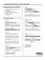
1
®
YAMAHA
AUTHORIZED
PRODUCT MANUAL
MUSIC SYNTHESIZER
YAMAHA
MUSIC SYNTHESIZER
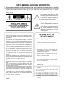
SUPPLEMENTAL MARKING INFORMATION
This information on safety is provided to comply with U.S.A. laws, but should be observed by users in all countries.
YAMAHA Digital Musical Instrument Products will have either a label similar to the graphic shown below or a molded/
stamped facsimile of the graphic on its enclosure. The explanation of these graphics appears on this page. Please observe all
cautions indicated.
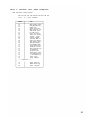
The exclamation point within an equilateral triangle is intended to alert the users to
the presence of important operating and
maintenance (servicing) instructions in the
literature accompanying the product.
The lightning flash with arrowhead symbol
within an equilateral triangle is intended to
alert the user of the presence of uninsulated "dangerous voltage" within the product's enclosure that may be of sufficient
magnitude to constitute a risk of electric
shock to persons.
FCC INFORMATION (USA)
While the following statements are provided to comply with FCC Regulations in the United States, the corrective measures listed below are applicable worldwide.
This series of YAMAHA professional music equipment uses frequencies
that appear in the radio frequency range and if installed in the immediate
proximity of some types of audio or video devices (within three meters),
interference may occur. This series of YAMAHA professional music equipment has been type tested and found to comply with the specifications set
for a class B computing device in accordance with those specifications
listed in subpart J of part 15 of the FCC rules. These rules are designed to
provide a reasonable measure of protection against such interference.
However, this does not guarantee that interference will not occur. If your
professional music equipment should be suspected of causing interference
with other electronic devices, verification can be made by turning your professional music equipment off and on. If the interference continues when
your equipment is off, the equipment is not the source of interference. If
your equipment does appear to be the source of the interference, you
should try to correct the situation by using one or more of the following
measures:
Relocate either the equipment or the electronic device that is being affected by the interference. Utilize power outlets for the professional music
equipment and the device being affected that are on different branch (circuit breaker or fuse) circuits, or install AC line filters.
In the case of radio or TV interference, relocate the antenna or, if the antenna lead-in Is 300 ohm ribbon lead, change the lead-in to a co-axial type
cable.
If these corrective measures do not produce satisfactory results, please
contact your authorized YAMAHA professional products dealer for suggestions and/or corrective measures.
If you cannot locate a franchised YAMAHA professional products dealer in
your general area contact the Electronic Service Division, YAMAHA Corporation of America, 6600 Orangethorpe Ave., Buena Park, CA 90620, U.S.A.
If for any reason, you should need additional information relating to radio
or TV interference, you may find a booklet prepared by the Federal Communications Commission helpful:
"How to identify and Resolve Radio - TV Interference Problems". This
booklet is available from the U.S. Government Printing Office, Washington
IIMPORTANT NOTICE FOR
THE UNITED KINGDOM
Connecting the Plug and Cord
IMPORTANT. The wires in this mains lead are
coloured in accordance with the following code:
BLUE
: NEUTRAL
BROWN
: LIVE
As the colours of the wires in the mains lead of
this apparatus may not correspond with the
coloured markings identifying the terminals in
your plug proceed as follows:
The wire which is coloured BLUE must be connected to the terminal which is marked with the
letter N or coloured BLACK.
The wire which is coloured BROWN must be connected to the terminal which is marked with the
letter L or coloured RED.
This applies only to products distributed by YAMAHA-KEMBLE
MUSIC (U.K.) LTD.
CANADA
THIS APPARATUS COMPLIES WITH THE "CLASS B" LIMITS
FOR RADIO NOISE EMISSIONS SET OUT IN RADIO INTERFERENCE REGULATIONS.
D.C. 20402 - Stock No. 004-000-00345-4.
This applies only to products distributed by YAMAHA CORPORATION OF
AMERICA.
This applies only to products distributed by YAMAHA CANADA
MUSIC LTD.
SY55 Music Synthesizer
Operating Manual
Congratulations!
Your YAMAHA SY55 Music Synthesizer features a breakthrough voice architecture
that allows extensive sample layering and programmable dynamic timbre variation. With
the SY55, individual sampled "waves" — either those pre-programmed in ROM or others
available via plug-in waveform cards — are building blocks that you arrange and process
with a sophisticated dynamic filter system to create sound that's a perfect match for your
music. You also have pitch envelope generators, amplitude envelope generators, a range of
34 programmable effects, real-time sound control via a range of controllers, and a wealth
of other ways to customize your sound. Add to all this a sophisticated 8-track sequencer,
and you have a complete music production workstation as well as an outstanding performance tool.
The SY55 is one digital synthesizer that puts samples in their proper place. Rather than
rigid sounds that limit the musical outcome, the SY55's samples are flexible tools that the
musician can shape, color and combine to create an original world of sound.
MAIN FEATURES
Second-generation 16-bit AWM2 (Advanced Wave Memory) technology for superior sound.
Versatile 1, 2, or 4-element voice architecture and complex envelope generators for extensive sample
layering capability.
Sophisticated dynamic filter system offers unlimited real-time timbre variation.
74 waveform samples in ROM.
64 preset voices in ROM.
64-voice internal RAM memory.
External waveform and voice card slots.
Multi-play mode allows independent control of up to 16 voices.
16 memory locations for multi-play setups.
Drum voices allow 61 different drum and other waveforms to be assigned to different keys.
Sophisticated built-in 8-track sequencer takes full advantage of the multi-play mode and drum-set voices.
Velocity switching for expressive power.
Extensive voice editing functions.
Keyboard initial and after touch response.
A range of controllers: pitch wheel, modulation wheel, continuous slider, breath controller jack, foot
volume jack, sustain switch jack.
34 high-quality programmable digital effects built in.
Stereo output.
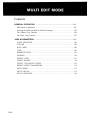
Contents
PRECAUTIONS
...........................................................2
HOW TO USE THIS OPERATION MANUAL ..............................3
THE CONTROLS & CONNECTORS
TUTORIALS
..................................... 4
........................................................... 10 *
1. SETTING UP YOUR SYSTEM . . . . . . . . . . . . . . . . . . . . . . . . . . . . . . . . . . . . . . . . . . 11
2. SELECTING AND PLAYING VOICES . . . . . . . . . . . . . . . . . . . . . . . . . . . . . . . . . . . 13
3. THE MULTI PLAY MODE . . . . . . . . . . . . . . . . . . . . . . . . . . . . . . . . . . . . . . . . . . . . . . 1 9
4. RECORDING & PLAYBACK WITH THE SEQUENCER .................... 27
5.
EDITING VOICES
.....................................................35
REFERENCE
VOICE EDIT MODE
. . . . . . . . . . . . . . . . . . . . . . . . . . . . . . . . . . . . . . . . . . . . . . . . . . . . 50 *
DRUM EDIT MODE . . . . . . . . . . . . . . . . . . . . . . . . . . . . . . . . . . . . . . . . . . . . . . . . . . . . .92 *
MULTI EDIT MODE
. . . . . . . . . . . . . . . . . . . . . . . . . . . . . . . . . . . . . . . . . . . . . . . . . . . . 104 *
SEQUENCER MODE
. . . . . . . . . . . . . . . . . . . . . . . . . . . . . . . . . . . . . . . . . . . . . . . . . . . . 116 *
UTILITY MODE . . . . . . . . . . . . . . . . . . . . . . . . . . . . . . . . . . . . . . . . . . . . . . . . . . . . . . . 130 *
ERROR MESSAGES
SPECIFICATIONS
INDEX
................................................ 144
.................................................... 147
. . . . . . . . . . . . . . . . . . . . . . . . . . . . . . . . . . . . . . . . . . . . . . . . . . . . . . . . . . . . . . . . 148
* See these pages for local tables of contents.
1
PRECAUTIONS (PLEASE READ THIS BEFORE PROCEEDING!!)
1. Avoid Excessive Heat, Humidity, Dust and Vibration
Keep the unit away from locations where it is likely to be exposed to high
temperatures or humidity — such as near radiators, stoves, etc. Also avoid
locations which are subject to excessive dust accumulation or vibration which
could cause mechanical damage.
2. Avoid Physical Shocks
Strong physical shocks to the unit can cause damage. Handle it with care.
3. Do Not Open The Case Or Attempt Repairs Or Modifications Yourself
This product contains no user-serviceable parts. Refer all maintenance to
qualified YAMAHA service personnel. Opening the case and/or tampering
with the internal circuitry will void the warranty.
4. Make Sure Power Is Off Before Making Or Removing Connections
Always turn the power OFF prior to connecting or disconnecting cables.
5. Handle Cables Carefully
Always plug and unplug cables — including the AC cord — by gripping
the connector, not the cord.
6. Clean With a Soft Dry Cloth
Never use solvents such as benzine or thinner to clean the unit. Wipe clean
with a soft, dry cloth.
7. Always Use the Correct Power Supply
The power requirements for the SY55 are clearly marked on the rear
panel. Make sure the specified mains voltage matches the voltage in your area
before using the unit!
8. Electrical Interference
Since the SY55 contains digital circuitry, it may cause interference and
noise if placed too close to TV sets, radios or similar equipment. If such a
problem does occur, move the SY55 further away from the affected equipment.
9. Memory Backup
The SY55 contains a special long-life battery that retains the contents of
its internal RAM memory even when the power is turned OFF. The backup
battery should last for approximately 5 years. When the battery voltage drops
to a level that is too low to maintain the memory contents, the following
message will appear on the SY55 display when the power is turned ON:
If this display appears, have the backup battery replaced by qualified
YAMAHA service personnel. DO NOT ATTEMPT TO REPLACE THE
BACKUP BATTERY YOURSELF!
2
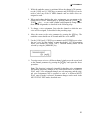
HOW TO USE THIS OPERATIONAL MANUAL
This operation manual is broadly divided into two main sections — TUTORIALS and REFERENCE.
What's In the
TUTORIALS Section
The TUTORIALS section contains five separate tutorials that take you
step-by-step through the main procedures you will need to know to become
familiar with your SY55:
1. SETTING UP YOUR SYSTEM [Page 11]
Basic system connections.
2. SELECTING AND PLAYING VOICES [Page 13]
Selecting and playing voices from the PRESET, INTERNAL and
CARD voice banks.
3. THE MULTI PLAY MODE [Page 19]
Creating multi-voice setups for use with the SY55 sequencer.
4. RECORDING & PLAYBACK WITH THE SEQUENCER [Page 27]
Using the SY55's internal sequencer to record and play back your
original compositions.
5. EDITING VOICES [Page 35]
The basic information you need to know about the AWM2 tone
generation system in order to edit voices quickly and efficiently,
and general procedure for editing and creating new voices.
We recommend that you go through the tutorials in sequence while actually carrying out the procedures on your SY55. Once you've gone through
the entire TUTORIALS section in this way, you should be familiar enough
with the SY55 to need only the REFERENCE section in future.
What's In the
REFERENCE Section
The REFERENCE section is the "nuts and bolts" section of the manual,
individually describing each of the SY55's many functions or "jobs" in
detail. The REFERENCE section is divided into five sub-sections, each
describing the various jobs within a particular SY55 mode.
1. VOICE EDIT MODE [Page 50]
2. DRUM EDIT MODE [Page 92]
3. MULTI EDIT MODE [Page 104]
4. SEQUENCER MODE [Page 118]
5. UTILITY MODE [Page 130]
Once you have become completely familiar with the way the SY55
works by going through the TUTORIALS section, you should only need to
refer to the REFERENCE section from time to time to get details on jobs
you've never used before, or refresh your memory about jobs that you don't
use very often.
Each sub-section or the REFERENCE section has its own table of contents, so you should be able to locate any particular job quickly and easily.
Functions and references can also be located by referring to the INDEX at
the back of the manual.
3
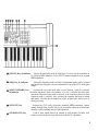
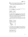
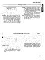
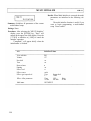
THE CONTROLS & CONNECTORS
FRONT PANEL
4
Keyboard
The SY55 keyboard is both velocity and after-touch sensitive for broad
expressive control.
[PITCH] Wheel
This self-cenetering pitch bend wheel allows smooth upward and downward pitch bends.
[MODULATION] Wheel
Can be assigned to apply pitch modulation, amplitude modulation, cutoff
modulation, envelope generator bias, and other effects.
MASTER VOLUME
Control
Adjusts the volume of the sound delivered via the rear-panel OUTPUT
and PHONES jack.
[SEQUENCER] Keys
& Indicator
Control the record, play and measure selection functions of the internal
sequencer.
[INTERNAL], [CARD]
and [PRESET] Keys
Select the data bank — internal, card or preset — from which voices or
multi-play setups will be selected.
[VOICE] Key & Indicator
Selects the normal voice play mode in which any of the SY55's preset,
internal or card voices can be played via the keyboard or an external controller connected to the MIDI IN connector.
[MULTI] Key & Indicator
Selects the multi-play mode in which up to 16 voices can be controlled on
16 different MIDI channels via the SY55's internal sequencer or an external
MIDI sequencer.
[SEQ] Key & Indicator
Selects the sequencer mode in which 8 independent tracks can be recorded
and played back using the various instruments in one of the SY55 multi-play
setups.
[EDIT/COMPARE] Key
Activates the voice edit mode when a voice between 1 and 62 is selected,
& Indicator
the drum edit mode when voice number 63 or 64 is selected, the multi-play
edit mode if the multi-play mode is selected, or the sequencer edit mode if the
sequencer mode is selected. Also activates the compare function in certain
edit modes, allowing quick comparison of the original and edited voice or
multi-play setup.
[UTILITY] Key
Accesses the SY55 utility functions including MIDI parameters, master
tuning, transposition, overall velocity curve selection, effect on/off switching,
memory card formatting and save/load operations.
[STORE/COPY] Key
Used to store edited data to an internal or card memory location. Also
selects several handy data copy functions in the SY55 edit modes.
5
Liquid Crystal Display
Panel
This 16-character x 2-line backlit liquid crystal display panel shows the
selected voice or multi-play setup name in the voice or multi-play modes, as
well as job names and parameters in the sequencer, utility, and edit modes.
[DATA ENTRY] Control
The [DATA ENTRY] control is the fastest way to select a value or item
from a large range when editing.
[-1/NO] and [+1/YES]
Keys
Select voices and multi-play setups, and are used to edit parameter values
in any of the SY55 edit modes. Either key can be pressed briefly for single
stepping in the specified direction, or held for continuous scrolling. These
keys are also used to answer the "Sure?" confirmation prompt when saving or
initializing data.
and
[PAGE
[PAGE
Cursor Keys
and
Keys
Move the screen cursor from parameter to parameter in many of the SY55
editing functions.
These keys are used primarily to select the various function screens in the
SY55 voice, multi-play, drum, and sequencer editing modes, as well as in the
utility mode.
[JOB] Key
Allows fast, direct access to any of the SY55 voice, drum, multi-play, and
sequencer editing jobs.
[SELECT] Key
Allows selection of voice elements and filters during voice editing, or
track record and mute assignments in the sequencer mode.
Numeric Keys
The SY55 numeric keys allow direct selection of voices or multi-play
setups, editing jobs and parameter values. These keys also function as track
and note-length selectors in the sequencer mode.
[ENTER] and [EXIT]
Keys
The [ENTER] key is used to enter job subsets while editing, initiate data
save and initialize operations, start demo playback, etc. The [EXIT] allows
you to immediately exit from editing job subsets, exit from any editing or
utility mode, stop demo playback, etc.
DATA and WAVEFORM
The DATA card slot accepts YAMAHA MCD64 or MCD32 Memory
Card Slots
Cards for storage and retrieval of SY55 voices, multi-play setups and system
data.
The WAVEFORM card slot accepts pre-programmed waveform cards —
i.e. cards containing sets of sampled waveforms for use in SY55 voices.
6
TUTORIALS SECTION
Contents
1. SETTING UP YOUR SYSTEM . . . . . . . . . . . . . . . . . . . . . . . . . . . . . . . . . . . . . . . . . 11
Connections . . . . . . . . . . . . . . . . . . . . . . . . . . . . . . . . . . . . . . . . . . . . . . . . . . . . . . . . . . . . . 11
Power-on Procedure . . . . . . . . . . . . . . . . . . . . . . . . . . . . . . . . . . . . . . . . . . . . . . . . . . . . . . 11
Enjoy the Demos . . . . . . . . . . . . . . . . . . . . . . . . . . . . . . . . . . . . . . . . . . . . . . . . . . . . . . . . . 12
2. SELECTING AND PLAYING VOICES . . . . . . . . . . . . . . . . . . . . . . . . . . . . . . . 13
The PRESET, INTERNAL and CARD Voice Banks . . . . . . . . . . . . . . . . . . . . . . . . . . . 13
Selecting the VOICE PLAY Mode, a Voice Bank, and Voice . . . . . . . . . . . . . . . . . . . 16
Voice Numbers 63 and 64 are Drum-set Voices . . . . . . . . . . . . . . . . . . . . . . . . . . . . . . . 18
3. THE MULTI PLAY MODE . . . . . . . . . . . . . . . . . . . . . . . . . . . . . . . . . . . . . . . . . . . . . . 19
MULTI PLAY Setups . . . . . . . . . . . . . . . . . . . . . . . . . . . . . . . . . . . . . . . . . . . . . . . . . . . . . 19
MULTI PLAY Mode, Bank and Setup Selection . . . . . . . . . . . . . . . . . . . . . . . . . . . . . . . 2 0
MULTI PLAY Polyphony and Dynamic Note Allocation . . . . . . . . . . . . . . . . . . . . . . . 2 0
Checking and Modifying MULTI PLAY Voice Assignments . . . . . . . . . . . . . . . . . . . . 2 0
Creating an Original MULTI PLAY Setup . . . . . . . . . . . . . . . . . . . . . . . . . . . . . . . . . . . 2 2
Storing an Edited MULTI PLAY Setup . . . . . . . . . . . . . . . . . . . . . . . . . . . . . . . . . . . . . . 2 5
Conclusion
. . . . . . . . . . . . . . . . . . . . . . . . . . . . . . . . . . . . . . . . . . . . . . . . . . . . . . . . . . . . . . 26
4. RECORDING & PLAYBACK WITH THE SEQUENCER . . . . . . . . . . . . . 27
The Sequencer/Multi-Play Interface . . . . . . . . . . . . . . . . . . . . . . . . . . . . . . . . . . . . . . . . . 2 7
Realtime Recoding: Replace & Overdub . . . . . . . . . . . . . . . . . . . . . . . . . . . . . . . . . . . . . 2 8
Step Recording . . . . . . . . . . . . . . . . . . . . . . . . . . . . . . . . . . . . . . . . . . . . . . . . . . . . . . . . . . . . . . . . . 31
Playback
................................................................34
Conclusion
. . . . . . . . . . . . . . . . . . . . . . . . . . . . . . . . . . . . . . . . . . . . . . . . . . . . . . . . . . . . . . 34
5. EDITING VOICES
.....................................................35
SY55 Voicing Basics . . . . . . . . . . . . . . . . . . . . . . . . . . . . . . . . . . . . . . . . . . . . . . . . . . . . . . 3 5
The SY55 Voice Parameter Chart . . . . . . . . . . . . . . . . . . . . . . . . . . . . . . . . . . . . . . . . . . . 3 8
Programming the "VeloChorus" Voice . . . . . . . . . . . . . . . . . . . . . . . . . . . . . . . . . . . . . . . 4 1
Storing an Edited Voice
...................................................46
Conclusion
..............................................................47
10
TUTORIALS
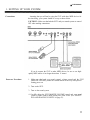
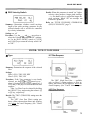
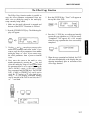
1. SETTING UP YOUR SYSTEM
Connections
Assuming that you will not be using the SY55 with other MIDI devices for
the time being, your system should be set up as shown below.
CAUTION!!: Make sure that both the SY55 and your sound system are turned
OFF when making connections.
If you do connect the SY55 to other MIDI devices, be sure to use highquality MIDI cables of not longer than about 15 meters.
Power-on Procedure
1. Make sure that both your sound system's volume control and the SY55
[MASTER VOLUME] control are turned almost all the way down prior to
turning power on.
2. Turn on the SY55.
3. Turn on the sound system.
4. Carefully adjust the SY55 [MASTER VOLUME] control and your sound
system's volume control while playing one of the voices (see "SELECTING AND PLAYING VOICES on page 13).
11
Enjoy the Demos
The SY55 is programmed with three demo tunes that you might enjoy listening to after setting up your system. Take a short break and enjoy the
demos:
1. Press and then release the SEQUENCER
time.
and
keys at the same
2. Press the [ENTER] key to start demo playback.
3. Press the [EXIT] key when you want to stop demo playback. Pressing
[EXIT] a second time returns you to the mode the SY55 was in prior to the
demo playback mode.
12
TUTORIALS
2. SELECTING AND PLAYING VOICES
The PRESET, INTERNAL
Here's a global view of the SY55 system:
and CARD Voice Banks
Please note that the voices played by the SY55 can come from three different sources: the PRESET voice bank, the INTERNAL voice bank, or a CARD
voice bank:
PRESET
The PRESET voice bank contains 64 pre-programmed voices in ROM
(Read Only Memory) that cannot be overwritten or changed in any
way. The PRESET voice bank is represented on the display by the
letter "P".
INTERNAL
The INTERNAL voice bank is a RAM (Random Access Memory) area
into which you can store up to 64 voices that you create or load from
an external memory card. The INTERNAL voice bank is represented
on the display by the letter "I".
CARD
The CARD memory bank is a YAMAHA MCD64 or MCD32 Memory
Card (or pre-programmed voice card) plugged into the SY55 DATA
card slot on the front panel. Memory cards are convenient for external
storage and transportation of voices that you or others create. You can
also store sets of related voices on different memory cards. An MCD32
Memory Card allows storage of up to 64 voices. An MCD64 Memory
Card holds two banks of 64 voices each — a total of 128 voices per
card. The CARD voice bank is represented on the display by the letter
"C" (the second bank of MCD64 cards is represented by a reversed
"C").
13
Any voice in any of these voice banks can be selected and played while
the SY55 is in the VOICE PLAY mode.
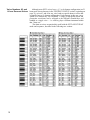
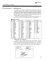
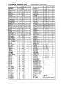
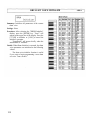
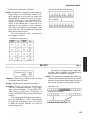
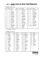
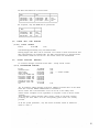
PRESET VOICE LIST
No.
EL*
1
2
3
4
5
6
7
8
9
10
11
12
13
14
15
16
17
18
19
20
21
22
1
2
2
2
4
2
2
2
4
4
2
4
2
2
1
2
2
2
2
2
1
4
Name
No.
EL
Piano
Voyager
Pro55Brass
Elektrodes
Zuratustra
DawnChorus
GX Dream
GrooveKing
DistGuitar
ZenAirBell
FullString
Jazz Man
ClassPiano
Rock Piano
DX E.Piano
Hard EP
Cry Clav
Funky Clav
Deep Organ
Warm Organ
Trumpet
Slab Brass
23
24
25
26
27
28
29
30
31
32
33
34
35
36
37
38
39
40
41
42
43
44
4
2
2
1
1
2
2
2
2
1
2
2
2
2
1
2
2
2
2
1
2
2
Name
No.
EL
Big Band
Orch Brass
SynthBrass
Flule
Saxophone
FolkGuitar
12 String
MuteGuitar
SingleCoil
Pick Bass
Thumb Bass
SynBadBass
VCO Bass
Violin
ChamberStr
VCF String
Nova Quire
Vibraphone
Takerimba
Gloken
DigiBell
Oriental
45
46
47
48
49
50
51
52
53
54
55
56
57
58
59
60
61
62
63
64
2
2
2
4
4
2
4
2
2
2
2
2
4
2
4
2
4
2
(61)
(61)
Name
VCO Lead
Spirit VCF
OZ Lead
Get Lucky
Gamma Band
Metal Reed
Modomatic
DataStream
Mystichoir
St.Michael
Scatter
Triton
Amazon
SatinGlass
BrassChime
Piano Mist
Xanadu
WdBass Duo
Drum Set 1
Drum Set 2
* EL=Number of elements sec page 35.
14
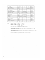
No.
Name
Comments
P01
P02
P03
P04
P05
P06
P07
P08
P09
P10
P11
P1 2
P13
P14
P1 5
P16
P17
P1 8
P1 9
P20
P21
P22
P23
Piano
Voyager
Pro55Brass
Elektrodes
Zaratustra
DawnChorus
GX Dream
GrooveKing
DistGuitar
ZenAirBell
FullString
JazzMan
ClassPiano
RockPiano
DX E.Piano
Hard EP
Cry Clav
Funky Clav
Deep Organ
Warm Organ
Trumpet
Stab Brass
Big Band
P24
Orch Brass
Orthodox acoustic piano.
Choir with "sizzle." Play long chords.
Fat analog brass pad.
Mellow electric piano.
Big orchestra. Brass volume on MW.
Breathy choir. MW fades out breath.
A punchy voice reminiscent of the YAMAHA GX1.
Classic funky, resonant synth voice.
Heavy guitar. Slow fade to feedback.
Percussive bell/gong combination.
Light touch for small, heavy for large string section.
Split wood bass and trumpet. MW swaps horns.
Classical Grand Piano
Fat piano. Perfect for chord work.
Electronic piano.
Electric piano with sharp attack and hard tone.
Automatic "wah" clav with resonant attack.
Fat, funky clav.
Rock Organ
Full, rich organ with rotating speaker effect.
Solo trumpet.
Thin pop brass section.
Big unison horn section. Play in octaves. MW fades to solo
trumpet.
Big classical brass section with pan.
TUTORIALS
No.
Name
Comments
P25
P26
P27
P28
P29
P30
P31
P32
P33
P34
P35
P36
P37
P38
P39
P40
P41
P42
P43
P44
P45
P46
P47
P48
P49
SynthBrass
Flute
Saxophone
FolkGuitar
12 String
MuteGuitar
SingleCoil
Pick Bass
Thumb Bass
SynBadBass
VCO Bass
Violin
ChamberStr
VCF String
Nova Quire
Vibraphone
Takerimba
Glocken
DigiBell
Oriental
VCO Lead
Spirit VCF
OZ Lead
Get Lucky
Gamma Band
P50
P51
P52
P53
P54
P55
P56
P57
P58
P59
P60
P61
P62
P63
P64
Metal Reed
Modomatic
DataStream
Mystichoir
St.Michael
Scatter
Triton
Amazon
SatinGlass
BrassChime
Piano Mist
Xanadu
WdBass Duo
Drum Set 1
Drum Set 2
Powerful synth brass pad.
Breathy when played hard.
Solo sax with lots of presence.
Steel-string acoustic folk guitar.
Full 12-string guitar.
Muted electric guitar.
Single-coil electric guitar pickup.
Punchy picked bass.
Play hard for slap bass sound.
Funky synth bass.
Fat analog bass.
Solo violin with after-touch vibrato.
Small violin section.
Analog synth strings. Brightness on MW.
Choir with a unique attack.
Traditional vibrophone with tremolo on MW.
Bamboo marimba. Brightness on MW.
Glockenspiel. Brightness on MW.
Spacious synth bell.
Oriental orchestra. Light touch for string section only.
Analog sawtooth lead voice.
Analog synth with big, slow filter sweep.
Soft synth lead.
Fat square-wave synth sound with detune on MW.
Oriental percussion ensemble. MW fades in metal drums
and bells.
Harmonica or accordion with after-touch pitch bend.
Choir with big MW filter sweep.
Best with long notes.
Play long chords for shifting notes.
Choir with bells on release.
Voice on staccato notes, filtered synth on long tones.
Best with long chords.
Wide touch range.
Metallic, spacious synth voice.
Filtered brass with chimes.
Piano bell. MW fades to staccato filtered voice.
Solo multi-tuned flute.
Split wood bass and piano.
Drum set including bass and sound effects.
Drum set including bass and sound effects.
15
Selecting the VOICE
PLAY Mode, a Voice
Bank, and Voice
1. If the VOICE PLAY mode is not already selected — as indicated by a lit
[VOICE] key LED and "VOICE PLAY" across the top of the LCD — press
the [VOICE] key to select it.
2. The [INTERNAL], [CARD] and [PRESET] keys are used to select the desired
voice bank. If no memory card is inserted in the DATA slot, pressing the
[CARD] key has no effect.
If a 2-bank memory card such as an MCD64 is inserted into the DATA
slot and both banks of the card are properly formatted ("REFERENCE"
section, page 138), pressing the [CARD] key alternately selects bank 1 (indicated by "C" on the display) or bank 2 ("C" on the display).
3. The [-1/NO] and [+1/YES] keys can be used to select the desired voice
within the current bank. Holding the [-1/NO] and [+1/YES] causes continuous scrolling in the specified direction.
Any voice can also be directly selected by inputting its number via the
numeric keys and then pressing [ENTER]. The entered number will flash
on the display until the [ENTER] key is pressed, indicating that a new
voice number has been selected but the voice has not yet been recalled.
16
TUTORIALS
Special technique: If you press the [SELECT/HOLD] key while in the
voice play mode, "Hold" will appear in the upper right-hand comer of the
display. This function "holds" the current tens digit of the voice number
so that pressing a numeric key changes only the ones digit, directly calling
the corresponding voice without the need to press the [ENTER] key. If, for
example, the [SELECT/HOLD] key is pressed while a voice in the thirties is
selected, then pressing numeric key [1] will immediately select voice
number 31, the [5] key will immediately call voice number 35, etc. The
hold mode can be released by pressing the [SELECT/HOLD] key a second
time.
4. Play the selected voice via the SY55 keyboard.
If you don't get any sound at this point:
Make sure your sound system is turned ON and the volume is turned
up to a reasonable level.
Make sure that the SY55 MASTER VOLUME control is turned up to a
reasonable level.
Check all connections.
17
Voice Numbers 63 and
Although most SY55 voices have a 1, 2 or 4-element configuration (we'll
64 are Drum-set Voices learn more about elements in the "EDITING VOICES" section, beginning on
page 35), voices 63 and 64 in any voice bank are special drum-set voices that
essentially have a 61-element configuration. Each element, in this case, corresponds to a different key on a keyboard. A range of high-quality drum and
percussion waveforms can be assigned to the different elements/keys and
handled as a single voice — i.e. each key plays a different instrument within
that "drum set."
The drum-set voices are particularly useful with the SY55's MULTI PLAY
mode and sequencer, described in the following two sections.
18
TUTORIALS
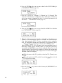
3. THE MULTI PLAY MODE
MULTI PLAY Setups
The SY55 MULTI PLAY (multi-timbre) mode allows different voices to
be assigned to up to 16 different MIDI channels. This allows you to record
and play multi-voice compositions using the SY55's internal 8-track sequencer, or an external sequencer if desired.
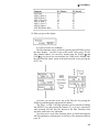
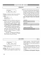
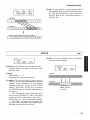
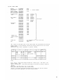
Here's an example — the preset "POP" multi-play setup (MULTI P01):
MULTI P01: POP instruments and channel assignments
Channel-1
Channel-2
Channel-3
Channel-4
Channel-5
Channel-6
Channel-7
Channel-8
Channel-9
voice
voice
voice
voice
voice
voice
voice
voice
voice
Pick Bass
Deep Organ
Trumpet
Saxophone
off
off
off
Drum Set 2
off
Channel-16 voice: off
In addition to 16 PRESET MULTI PLAY setups including the one described above, 16 INTERNAL memory locations are provided for complete
"MULTI PLAY" setups including voice-to-channel assignments, individual
voice volume, note shift, tuning, panning, and effects. This allows you to
create up to 16 original "orchestras" with different combinations of voices
that can be recalled whenever needed. MULTI PLAY setups can also be
stored on external memory cards in the same way as ordinary voices.
19
MULTI PLAY Mode,
Bank and Setup Selection
The MULTI PLAY mode, memory banks and individual MULTI PLAY
setups are selected in the same way as the SY55 voices:
[MULTI] to select the MULTI PLAY mode.
[INTERNAL], [CARD] or [PRESET] to select the desired memory bank.
[-1/NO] and [+1/YES] or numeric keys plus [ENTER] to select the desired MULTI PLAY setup.
MULTI PLAY Polyphony
Since the SY55 can produce a maximum of 16 notes at the same time (16and Dynamic Note Allo- note polyphony), the number of simultaneous notes that each voice in a
cation
MULTI PLAY setup can produce depends on the number of voices being
played at the time. If all 16 voices are played at once, each can only produce a
single note. On the other hand, if only one voice is being played the SY55's
"Dynamic Note Allocation" feature allows 16 notes to be played simultaneously by that one voice even if 16 voices are assigned.
The SY55 also has a RESERVED NOTE function that allows you to
specify a minimum number of notes for each voice ("REFERENCE" section,
page 110).
Checking and Modifying
MULTI PLAY Voice Assignments
Here's how you can see what voices are assigned to the various channels
in any MULTI PLAY setup, and change the voice assignments temporarily to
try out alternative voices.
1. When you first select the MULTI PLAY mode by pressing the [MULTI]
key, a display similar to the following will appear:
At this point you can use the [-1/NO] and [+1/YES] keys or numeric
keys plus [ENTER] to select any of the 16 MULTI PLAY setups within the
current bank.
or [PAGE
key after selecting the
2. If you press either the [PAGE
desired MULTI PLAY setup, a display similar to the following will appear:
This display allows you to see and change the voices assigned to each
channel. In the above display, "CH 1=P32" on the bottom line indicates that
voice P32 is assigned to channel 1 (CH 1). Voice P32 is "Pick Bass," as
indicated on the top display line. Note the underline cursor under the "1" of
"CH 1."
20
TUTORIALS
3. While the underline cursor is positioned below the channel (CH) parameter, the [-1/NO] and [+1/YES] keys or numeric and [ENTER] keys can be
used to select any of the 16 MIDI channels and see which voices are
assigned to each.
4. When you're done checking the voice assignments you can return to the
normal MULTI PLAY mode display by pressing either the [PAGE
or
[PAGE
key ... or you could continue and temporarily change one or
more voices assignments as described in the following steps.
5. To change a voice assignment, first select the channel to which the new
voice will be assigned, as described in the preceding steps.
6. Move the cursor to the voice parameter by pressing the
key. The
underline cursor should now be located under the voice number.
7. Use the [-1/NO] and [+1/YES] keys or numeric and [ENTER] keys to select
the new voice for that channel, or turn the channel "off" (decrementing
below voice number 01 selects "off"). Different memory banks can be
selected by using the [MEMORY] key.
8. To assign a new voice to a different channel, simply move the cursor back
to the channel parameter by pressing the
key and repeat the above
procedure.
Note: This function is primarily intended for checking voice assignments
and making temporary changes to try out different voices in a MULTI
PLAY setup. Voice assignment changes are only temporary and the original voice assignments will be restored as soon as a different MULTI
PLAY setup or mode is selected. Permanent changes can be made in the
MULTI PLAY EDIT mode, described next.
21
Creating an Original
MULTI PLAY Setup
In this section we'll go through the steps to create a simple "Jazz Quartet"
MULTI PLAY setup consisting of the following voices:
Channel 1 .........P01 Piano
Channel 2 .........P62 WdBass Duo
Channel 3 .........P40 Vibraphone
Channel 4 .........P63 Drum Set 1
Channels 5 ... 16 ...off
Note: P62 WdBass Duo is actually a split voice with wood bass ranging
from C-2 to E3 and piano on all higher keys up to G8.
1. If it is not already selected, press [MULTI] to select the MULTI PLAY
mode.
2. Use the [INTERNAL], [-1/NO] and [+1/YES] keys to select MULTI PLAY
setup I01.
3. Press [EDIT/COMPARE] to enter the MULTI PLAY EDIT mode.
4. If a display similar to the following is not showing, press the [JOB] key,
then the numeric" [1] key, and finally the [ENTER] key to select it (while
the [PAGE
and [PAGE
keys can be used to step forward and backward through the jobs in any edit mode, using job numbers is often the
fastest way to access a specific editing job — "REFERENCE" section,
page 52).
This is the display for the MULTI PLAY EDIT mode voice assignment function ("REFERENCE" section, page 108).
5. The
and
cursor keys are used to move the cursor
to the
desired channel (a channel number between CH1 and CH16 will appear in
the upper right-hand comer of the display), and the [DATA ENTRY]
control, [+1/YES] and [-1/NO], keys or numeric and [ENTER] keys are used
to assign the desired voice to the selected channel.
With the cursor at the channel-1 position, make sure the P01 (Piano)
voice is selected.
Move the cursor to the channel-2 position by pressing
, then select
voice P62 (WdBass Duo).
22
Move the cursor to the channel-3 position by pressing
voice P40 (Vibraphone).
Move the cursor to the channel-4 position by pressing
voice P63 (Drum Set 1).
, then select
, then select
TUTORIALS
Move the cursor to all the remaining channel positions (5 ... 16) and
turn each "off by holding the [-1/NO] key until the "off" display
appears. Note that the cursor can be moved past the end of the display
screen to access the remaining channels in groups of four.
key to move to the next MULTI PLAY EDIT mode
6. Press the [PAGE
job: Volume ("REFERENCE" section, page 108).
7. The volume job operates in basically the same way as the voice assigncursor keys are used to select
and
ment job described above. The
the channel/voice for which the volume is to be adjusted, then the [DATA
ENTRY] control, [+1/YES] and [-1/NO] keys, or numeric and [ENTER] keys
are used to set the desired volume. A setting of "0" produces no sound
while a setting of "127" produces maximum volume.
With the Jazz Quartet setup, the relatively gentle wood bass sound
tends to become "buried" under the other instruments, so leave its volume
setting at the maximum of 127, and lower the other three voices to about
110.
Volume
Piano . . . . . . . . . . . . . 110
WdBass Duo .......127
Vibraphone . . . . . . . 110
Drum Set 1 .........110
8. Press the [JOB] key, the numeric [5] key, and then the [ENTER] key to
move to the Reserved Note job ("REFERENCE" section, page 110). We'll
skip the Note Shift and Tune ("REFERENCE" section, page 109) jobs for
this setup, since we don't need to tune or transpose the pitch of any of the
voices in the Jazz Quartet setup.
23
9. The main use for Reserved Note job is to ensure that a minimum number
of notes are available to specific instruments even under circumstances in
which less would normally be available. In this case we'll set channel 1
(Piano) to 8 since jazz piano tends to involve a lot of "thick" chord work,
and channel 3 (Vibraphone) to 4, which is enough for two-handed phrases.
This simply means that there will always be at least 8 notes available for
piano and 2 notes available for vibraphone (Vibraphone uses 2-elements:
2 elements x 2 notes = 4), no matter how many notes are played at the
same time by bass and drums. If the total number of notes played exceeds
16 at any instant, the bass or drum voice notes will be truncated rather
than the piano or vibes notes.
Reserved Note
Piano . . . . . . . . . . . . . 8
WdBass Duo ......0
Vibraphone . . . . . . . 4
Drum Set 1 . . . . . . . . 0
The
and
cursor keys are used to select the voice/channel, then
the [DATA ENTRY] control, [+1/YES] and [-1/NO] keys, or numeric and
[ENTER] keys are used to set the number of reserved notes.
10. Press the [PAGE
key to move to the next MULTI PLAY EDIT mode
job: Pan ("REFERENCE" section, page 110).
11. This job allows each individual voice in the setup to be panned to a
different position in the stereo sound field (you'll only hear this if you're
using a stereo sound system fed by the SY55 OUTPUT R and L/MONO
jacks).
As always, the
and
cursor keys are used to select the voice/
channel for which the pan position is to be set, then the [DATA ENTRY]
control, [+1/YES] and [-1/NO] keys, or numeric and [ENTER] keys are used
to set the pan position.
The upper line of the display also shows a graphic representation of
the stereo sound field with "L" representing "left" and "R" representing
"right." As you change the pan value the vertical bar will appear at the
corresponding position on the graphic display.
Set the pan positions of the Jazz Quartet voices as follows:
Pan
Piano . . . . . . . . . . . . . -17 (half way to the left)
WdBass Duo . . . . . . -9 (slightly to the left)
Vibraphone . . . . . . . + 1 7 (half way to the right)
Drum Set 1 . . . . . . . . +5 (slightly to the right)
12. Press the [PAGE
key once to move on to the Effect Level job ("REFERENCE" section, page 111).
24
TUTORIALS
13. The Effect Level job individually sets the effect level for each voice in the
setup. You know how to move the cursor around and change settings by
now.
Set the Effect Level for all four voices to 100 (this is equivalent to the
individual voice effect level settings).
Effect Level
Piano . . . . . . . . . . . . . 1 0 0
WdBass Duo ......100
Vibraphone .......100
Drum Set 1 ........100
A hall reverb effect is already selected for the I01 MULTI PLAY
setup, so we won't bother with the many possible effect settings for now
("REFERENCE" section, page 86).
14. Press the [PAGE
key twice to move on to the MULTI Name job ("REFERENCE" section, page 113).
15. Here's where we actually name our MULTI PLAY setup: "Jazz Quart".
The MULTI Name job allows a name of up to 10 characters to be assigned
cursor keys to place the
to the current setup. Use the
and
underline cursor under the character to be changed, then use the [DATA
ENTRY] control or [+1/YES] and [-1/NO] keys to select the desired character. Continue until the entire voice name has been programmed.
16. Press [MULTI] to exit from the edit mode and return to the MULTI PLAY
mode. The reversed letter "E" that appears to the right of the voice number
indicates that the MULTI PLAY setup has been edited.
Caution!!: If you select a different MULTI PLAY setup or mode at this
point, the edited MULTI PLAY setup will be erased. To keep an edited
setup, it must be stored to an INTERNAL or CARD memory location, as
described in the following section. For a special method of recalling a
multi-play setup lost in this way, see "MULTI RECALL" on page 113.
Storing an Edited
MULTI PLAY Setup
Now that you've created your first MULTI PLAY setup — "Jazz Quart"
— you'll want to store it to one of the SY55's 16 internal MULTI PLAY
memory locations or a memory card location.
1. After exiting the edit mode by pressing the [MULTI] key, press the [STORE/
COPY] key. The following display will appear:
25
The MULTI PLAY memory number on the top line indicates the
source setup — i.e. "Jazz Quart," the setup we just created. The MULTI
PLAY number after the arrow on the bottom line is the target setup — i.e.
the memory location to which we will store the edited setup.
2. The target memory location can be changed by using the [DATA ENTRY]
control, [+1/YES] and [-1/NO] keys, or numeric and [ENTER] keys. The
[INTERNAL] and [CARD] keys can be used to change banks, if necessary
(obviously you can't store to the read-only PRESET bank, or to a card if
no card is loaded).
3. When you're satisfied with the target memory location selection, press
[ENTER].
"Sure?" appears on the top line of the display, asking you to confirm
you intention to store to the selected target location. This confirmation
step is important because once you store, all previous data in the target
location is erased and completely replaced by the new data.
4. Press [+1/YES] to confirm and actually execute the store operation, or [-1/
NO] to cancel. "Executing!" will appear on the display during store, and
"Completed!" will appear briefly when the store operation is finished.
Your "Jazz Quart" MULTI PLAY setup has now been stored and can
be recalled whenever needed!
Note: See the ERROR MESSAGES section on page 144 for information
on memory-card related error messages.
Conclusion
26
If you've gone all the way through this section and followed all the
instructions, you've actually done much more than program your first MULTI
PLAY setup. You've learnt about many of the most important SY55 programming procedures and, as a result, should find the next tutorial easy to handle.
There are a few functions and features of the MULTI PLAY mode that we
haven't looked at in this tutorial. Refer to the "REFERENCE" section for
details.
TUTORIALS
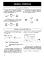
4. RECORDING & PLAYBACK WITH THE SEQUENCER
In the preceding section we learned about the SY55 multi-play mode, and
how to create original multi-play setups. In this section we'll see how the
SY55 sequencer can be used to record the various parts of a musical composition, and "drive" the corresponding instruments of a multi-play setup. The
SY55 sequencer can hold up to 8 separate "songs," each with its own song
name ("REFERENCE" section, page 127), that can be selected and recorded
or played as required. Completed songs can also be stored to external memory
cards for long-term storage ("REFERENCE" section, pages 140 and 141).
The Sequencer/MuItiPlay Interface
The SY55 sequencer has 8 separate tracks, each of which can control a
separate multi-play instrument. Which track controls which instrument is
determined by both the multi-play setup MIDI channel assignments ("REFERENCE" section, page 108) and the sequencer track channel assignments
("REFERENCE" section, page 119). Normally, sequencer tracks 1 through 8
are assigned to the correspondingly numbered MIDI transmit channels, so
tracks 1 through 8 control the multi-play instruments assigned to MIDI channels 1 through 8, respectively.
In the example below, preset multi-play setup P01 ("POP") is selected. In
the "POP" setup, bass, organ, trumpet and saxophone are assigned to channels
1 through 4, channels 5 through 7 are off, drums are assigned to channel 8,
and channels 9 through 16 are off. We therefore have 5 active instruments
which will be controlled by the corresponding sequencer tracks.
There are basically two ways to record using the sequencer — realtime or
step. Both of these methods are described below.
27
Realtime Recording:
Replace & Overdub
Realtime recording allows you to directly record anything you play on the
keyboard, capturing the spontaneous timing, keyboard dynamics and controller operations of the performance. Using the realtime recording mode is, in
fact, very much like using a conventional tape recorder. Realtime recording is
best for parts you can play easily on the keyboard, and for passages in which
you want to retain the human "feel" of naturally varying timing and other
musical factors.
1. Before recording, press the [MULTI] key and select the multi-play setup
you intend to use, then press the [SEQ] key to enter the sequencer mode.
2. At this point you're in the sequencer play mode. The underline cursor will
be under the "SONG" (song number) parameter, so you can use the [DATA
ENTRY] control, [-1/NO] and [+1/YES] keys, or numeric and [ENTER] keys
to select the song number you want to record to (1 through 8).
3. Press the [RECORD] key. The [RECORD] key indicator will light and a
display similar to the following will appear.
4. Use the
and
keys to move the underline cursor to the parameter in and
the upper right-hand comer of the display, and use the [DATA ENTRY]
control or [-1/NO] and [+1/YES] keys to select the "repl" (replace) or
"over" (overdub) record mode.
The Replace Record Mode
Anything recorded in this mode replaces previously recorded material.
That is, previous data on the current track is erased and replaced by the
new material.
The Overdub Record Mode
Material recorded in the overdub mode is recorded "over" any previous material, so you end up with a combination of the previous and newlyrecorded data.
28
TUTORIALS
5. If necessary, the tempo, measure, and time signature parameters can also
be set at this time. The time signature can only be set if nothing has been
recorded in the current song. You can start recording from any measure
number within the range of already-recorded measures by setting the
measure parameter accordingly. The tempo can be set before recording
any track. This is useful because you might want to record complex
passages at a slower tempo to minimize mistakes.
Time Signatures
When setting the time signature, the cursor can be moved to the time
signature numerator or denominator so that these two values can be set
separately. Available time signature ranges are: 1/4 ... 4/4, 1/8 ... 8/8, and
1/16 ... 16/16.
6. Select the track you want to record by pressing the appropriate track key
(TR1 ... TR8, labelled in green below the numeric keys) while holding the
[SELECT] key. A display similar to the following will appear while the
[SELECT] key is held.
When the desired record track is selected, the corresponding instrument in the current multi-play setup will sound when the keyboard is
played.
7. Press the [RUN] key and start recording after a two-measure count-in. The
count-in is indicated visually on the LCD by "minus" measure numbers —
e.g. recording will actually begin after a two-measure count-in from -8 to
0 if 4/4 time is selected, -16 to 0 if 8/8 time is selected, etc. The "click"
metronome will also sound as long as the "CLICK SELECT" function is
set appropriately ("REFERENCE" section, page 118) and the rear-panel
[CLICK VOLUME] control is set to an appropriate level. After the count-in,
the measure numbers will increase as recording progresses. The [RUN]
key indicator also flashes to indicate the tempo — red on the first beat of
every measure and green on all other beats.
8. When you have finished playing the part for the current track, press the
[STOP] key to stop recording. Both the [RUN] and [RECORD] key indicators will go out, and "Executing!" will appear on the display briefly while
recorded data is being processed. After this, the SY55 will return to the
sequencer play mode.
29
9. You can now listen to the part you've just recorded by pressing the sequencer
key (see illustration below) to return to the first measure, and
then the [RUN] key. You can also use the forward and reverse keys to
move to any measure and listen to playback from that point.
Playback will stop automatically when the end of the recorded sequence is reached, or it can be stopped at any time by pressing the [STOP]
key.
10. When you're satisfied that the first track is OK, go back to step 5 and
select a new record track, then record. Continue this process until your
composition is complete. For difficult tracks you might want to use the
step record mode, described on the next page.
Punch-in Recording
Punch-in recording makes it possible to re-record (replace) a section
of a previously-recorded track without affecting the data before and after
the punch-in section. All operations are the same as for replace recording,
except that you must specify the measure numbers for the beginning and
end of the punch-in segment. If you select "punc" instead of "over" or
"repl," (see step 4, above) the display will appear as follows:
Move the cursor to the punch-in and punch-out point parameters and
set as required prior to recording. Other parameters within this display can
be set in the same way as for replace or overdub recording.
Once recording is started the sequence will play back until the punchin point is reached, then the replace record mode will be activated until the
punch-out point is reached, allowing you to record the new material. If
recorded material exists following the punch-out point, playback will
continue until the end of the sequence.
30
TUTORIALS
Step Recording
Step recording allows you to input parts note by note, rest by rest, without
having to actually play the part on the keyboard. This is ideal for entering
difficult parts from written music, or for extremely complex or fast passages
that would be impossible to play in real time.
The step recording mode can also be used to edit tracks previously
recorded using one of the realtime record modes, allowing you to add or erase
notes where necessary.
1. The sequencer and record standby modes are entered in the same was as
described in the "REALTIME RECORDING" section, above.
2. Instead of choosing the "repl" or "over" record mode, select "step." You
can also select a time signature at this point if nothing has been recorded
yet.
3. Press the [RUN] key, to call the step record edit display.
Step write input display line. Each dash represents a 32nd beat. Plus
signs mark the beginning of each beat specified by the selected time
signature. The example below corresponds to a 1/4 ... 4/4 time signature.
If an 8-beat time signature (1/8 ... 8/8) were selected, plus signs would
appear every 4 32nd beats. The cursor is placed under the appropriate
beat of the display line by using the
and
cursor keys or the sequencer
and
keys to enter notes or rests. The position of the
cursor is also reflected by the measure and beat number displays below.
4. Select the note length for the first note by pressing the corresponding
numeric key (standard notes are displayed in white above the keys), or by
incrementing/decrementing using the [-1/NO] and [+1/YES] keys. The number of 32nd-note segments corresponding to the selected note length will
be emphasized on the display. If you select 8th notes in 4/4 time, for
example, the display will look something like this:
31
Dotted Notes
Pressing the dot
key (numeric key
) adds half the value of the
currently displayed note length. If this results in a standard note length, it
is displayed as a dotted note. Otherwise it is displayed as a numeric value.
Triplets
Triplet-length notes are entered by first selecting the basic note length
— e.g. 8th notes if YOU want 8th-note triolets, 16th notes if you want 16note triplets, etc. — and then the
key (numeric key ). When a
note is being displayed
appears to the right of the note, while numeric
values are divided by two-thirds (since triplets squeeze three notes in the
space normally occupied by two, triplet notes are two-thirds the length of
their standard counterparts). You should normally enter triplet notes in
groups of 3, 6, 9, 12 or other multiples of 3, in order to end up with
standard note lengths.
Ties
Press the [TIE] key (numeric key ) immediately after entering a note
to tie that note to the next note entered. The tie function is cancelled if you
move the cursor between pressing the [TIE] key and entering the second
note.
5. When you've selected the required note length, play the note to be entered
on the keyboard. The entered note will appear as a diamond
on the
step record input display line. The cursor will move to the beginning of
the next note.
Press the [REST] key (numeric key
) instead of playing a note if you
6. Repeat steps 4 and 5 until the required material is entered. You can move
cursor keys or sequencer
the cursor back and forth using the
and
and
keys, adding notes wherever you like — even on top of
other notes to create chords.
Erasing Notes
To erase a note, move the cursor to that note and press the [ERASE]
key (numeric key ). The diamond note marker will disappear. If the diamond marks a chord, the entire chord will be erased.
Staccato and Slurred Notes
Staccato and slurred notes can be entered by using the Gate Time
key while the step record edit display is
function — press the [PAGE
showing.
32
TUTORIALS
Use the [DATA ENTRY] control or [-1/NO] and [+1/YES] keys to select
"Staccato:50%," "Normal: 80%," or "Slur:99%." The percentage values
are the gate time of the notes. Gate time is the time between the beginning
of one note and the beginning of the next. Once the desired gate time has
been set, press the [PAGE
key to return to the step record edit display
and continue recording.
Switching Voices Mid-track
You can switch to a different voice anywhere in a track by entering a
program change command at the required point. After moving the cursor
to the point at which you want to change voices in the step record edit
display, press the [PAGE
key once to select
key twice or the [PAGE
the program change display.
Select the desired bank and voice in the normal way, then press the
[ENTER] key. The display will return to the step record edit display, and a
"p" will occur at the point at which the program change command was
entered. Program change commands can be erased in the same was as
notes by using the [ERASE] key.
7. Press the [STOP] key to exit the step record mode and return to the
sequencer play mode.
33
Playback
The sequencer play mode is selected anytime you press the [SEQ] key
from another mode. The sequencer play display, shown below, allows
selection of the song number to play, the measure from which to begin
playback, and tempo.
Once the sequencer play mode has been selected, you can use the sequencer
and
keys to move to any measure from which you want to begin
playback, or the
key to move directly to the first measure. The [RUN] key
starts playback from the selected measure, and the [STOP] key stops playback
at any time.
Track Muting
If you press the [SELECT] key at any time in the sequencer play mode —
even while a sequence is playing — the track mute display appears.
Then, while holding the [SELECT] key, the TR1 through TR8 keys (numeric keys [7], [4], [1], [0], [8], [5], [2], and [-], respectively) can be used to
alternately engage or disengage muting for the corresponding track. A dash
appears in place of the track number when a track is muted.
Conclusion
34
Now that you now how to record and play back sequences with the SY55,
you'll want to take a look at the "SEQUENCER MODE" information beginning on page 116 of the reference section. There are many important editing
and other jobs that have not been described here, but which can make the
process of "sequencing" smoother and much more versatile.
TUTORIALS
5. EDITING VOICES
SY55 Voicing Basics
AWM2 Waveforms
"AWM2" is an acronym for YAMAHA's second-generation 16-bit Advanced Wave Memory. This is a digital waveform storage and reproduction
system that rivals the quality of the finest compact disc players, providing unprecedented clarity and realism in the reproduction of acoustic instruments
and other natural timbres. Technically speaking, AWM2 deals with 16-bit
wave data sampled at 32 or 48 kilohertz, 24-bit internal signal processing, and
high-resolution 22-bit digital-to-analog converters.
The SY55 contains 2 megabytes of of sampled waveform ROM, so you
have a choice of 74 built-in waveforms from which to construct voices.
PRESET WAVE LIST
Elements and Voice Architecture
Each SY55 voice is composed of one, two or four "elements." The only
limitation is that the maximum polyphony of the SY55 is 16 (i.e. the maximum number of notes that can be played simultaneously is 16). This means
that a 1-element voice can produce the full 16 notes, while a "layered" 2element voice can produce 8, and a layered 4-element voice can produce 4.
35
Each element can be assigned an AWM2 waveform from the 74 provided
in internal ROM, or others available on plug-in waveform cards. You can
have a single element voice that uses only a single waveform, or multielement voices that combine two or four different waveforms in a number of
ways. Each element has its own programmable 5-segment amplitude envelope
generator so you can "layer" waveforms enveloped in different ways to create
any number of unique sonic hybrids. See page 64 of the "REFERENCE"
section for a full description of the amplitude envelope generator parameters.
As an alternative to layering elements, each element can be assigned to a
different section of the keyboard for exotic split keyboard setups using the
low and high-note limit functions described on page 60 of the "REFERENCE"
section.
36
TUTORIALS
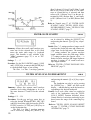
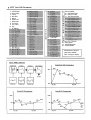
Each element also has a pitch envelope generator and two filter cutoff envelope generators that control the SY55's innovative digital filter system. The
block diagram below shows how the various operational blocks within each
element are interconnected.
Digital Filters
Each element has two digital filters. Filter 1 (FL1) is switchable for either
low-pass or high-pass response, while Filter 2 (FL2) is a low-pass type. Each
filter has its own 6-segment envelope generator so that a virtually unlimited
range of dynamic filtering patterns can be produced. See page 63 of the "REFERENCE" section for details on the filter cutoff envelope generators. Filter
cutoff can also be controlled by the element's LFO (low-frequency oscillator).
Low-pass and high-pass filters can be combined to create a bandpass response, or both filters can be set for low-pass operation — each with a rolloff
slope of 12-dB/octave — to produce a steep 24-dB/octave low-pass curve.
The filters also have a resonance parameter in the low-pass mode that allows
you to boost their cutoff-frequency peak — all the way into oscillation if you
like. The following graphs show the types of filter response that can be
achieved.
37
Other Programmable Parameters & Effects
For each element in any voice you can also control volume, note shift,
detuning, high and low note limits, high and low velocity limits for velocityswitched keyboard dynamics, pan position, LFO modulation, controller assignments and more. Of course, the standard pitch and modulation wheels
perform their familiar functions, but you can also assign any MIDI controller
to amplitude modulation, pitch modulation, filter cutoff modulation, direct
filter cutoff control, envelope generator bias and volume ... not to mention
after-touch pitch bias ("REFERENCE" section, pages 81 through 84).
You also have direct access to 34 digital effect programs including reverb,
delay, early reflection, tone control and distortion — each with several programmable parameters. See page 86 of the "REFERENCE" section for details
on the effects and their various parameters.
SY55 Voice Parameter
Chart
38
The voice parameter chart on the following page lists all of the programmable voice parameters — titled as they appear on the SY55 editing screen.
You might want to make copies of this chart in order to jot down parameters
as you program your own voices.
SY55 Voice Parameter Chart.
Voice Name:
TUTORIALS
39
SY55 Voice Parameter Chart.
40
Voice Name: VeloChorus
TUTORIALS
Programming the
"VeloChorus" Voice
Now that you've got the basic idea, try programming the VeloChorus
voice described below. VeloChorus is a 2-element voice in which the "Chorus" waveform is assigned to element 1 and the "Styroll" waveform is assigned to element 2. Both waveforms are enveloped and filtered, and the
Styroll waveform is "velocity switched" so it only appears — layered onto the
chorus sound — when you play the keys on your keyboard quite hard.
Here's the Voice Parameter Chart for the VeloChorus voice.
The changes are made in "real time" as you program. So don't be afraid to
play the voice via your keyboard/controller as you program, to hear the sound
as it gradually takes shape.
1. If it is not already selected, press [VOICE] to select the VOICE PLAY
mode.
2. Use the [INTERNAL], [-1/NO] and [+1/YES] keys to select VOICE I01.
3. Press [EDIT/COMPARE] to enter the VOICE EDIT mode.
4. Press the [JOB] key, the numeric [4] and [2] keys, and then the [ENTER]
key to select voice edit job 42: Voice Initialize.
5. The voice initialize function allows us to to create an "initialized" voice in
which all parameters are set to their "standard" values. This is useful
because the controller parameters — i.e. pitch wheel and modulation
wheel — are also set to function normally, so we won't have to go to the
trouble to program these particular parameters for this example ("REFERENCE" section, page 90).
Press the [ENTER] key.
"Sure?" appears on the top line of the display, asking you to confirm
you intention to initialize the voice. Press [+1/YES] to confirm and actually execute the initialize operation. "Completed!" will appear briefly
when the initialization is finished.
41
6. Press the [PAGE
key once to move ahead to the VOICE Mode job
("REFERENCE" section, page 58).
7. Press the [+1/YES] key to change "=1 Element" to "=2 Element". This
selects the 2-element voice configuration (the [-1/NO] and [+1/YES] keys
are just one means of changing the value of a selected parameter in the
edit modes — "REFERENCE" Section, page 53).
8. Press the [PAGE
key once to move ahead the AWM Wave Selection
job ("REFERENCE" section, page 58).
9. When the 2-element mode is selected (as it should be after the last step),
element 1 (EL1) and element 2 (EL2) are available and a different waveform from among the SY55's 74 preset waveforms can be assigned to
each. The unavailable elements are represented by
on the display.
The
and
cursor keys are used to move the cursor to the
desired element (EL1 or EL2 will appear in the upper right-hand comer of
the display), and the [DATA ENTRY] control, [+1/YES] and [-1/NO] keys,
or numeric and [ENTER] keys are used to assign the desired wave to the
selected element. The selected wave number is shown at the current cursor
location, and the full name of the assigned wave is shown in the upper
left-hand corner of the display.
With the cursor at the EL1 position, select the P31 (Chorus) waveform.
Move the cursor to the EL2 position by pressing
, then select the
P56 (Styroll) waveform.
10. Press the [PAGE
lion, page 47).
42
key to move to the Volume job ("REFERENCE" sec-
TUTORIALS
11. The volume job operates in basically the same way as the voice assignment job described above. The
and
cursor keys are used to select
the element for which the volume is to be adjusted, then the [DATA
ENTRY] control, [+1/YES] and [-1/NO] keys, or numeric and [ENTER] keys
are used to set the desired volume. A setting of "0" produces no sound
while a setting of "127" produces maximum volume.
For the VeloChorus voice, leave the Chorus volume setting at the
maximum of 127, and lower the Styroll setting to about 100.
12. Press the [JOB] key, the numeric [8] key, and then the [ENTER] key to
select the Vel. Limit/L job ("REFERENCE" section, page 61). We'll skip
the Note Shift ("REFERENCE" section, page 59), Detune, and Note Limit
("REFERENCE" section, page 60) jobs for this voice, since we don't need
to detune or transpose the pitch of either of the waveforms in the VeloChorus voice, or set note limits to create a split keyboard setup.
13. The Velocity Limit job is where we setup the VeloChorus voice's interesting velocity switching feature. This job lets us set the lowest velocity
value for a range of velocity values over which the element will produce
output. A little more explanation is in order:
Every MIDI "note on message" (the MIDI message that is transmitted
every time a note is played on a keyboard or other MIDI controller)
contains a "velocity" value that tells the tone generator how hard the note
has been played. The range of MIDI velocity values is from 1 to 127 —
thus the 1 ... 127 range of this function. By setting the low velocity limit
of the Styroll element to about "55", the Styroll portion of the voice will
only sound when a key is played hard enough to transmit a velocity value
greater than 55. The low velocity limit of the Chorus waveform is left at
"1" so that the Chorus element sounds no matter how hard or soft you play
the keys.
You should be getting quite familiar with the basic procedure by now:
the
and
cursor keys are used to select the element for which the
low velocity limit is to be set, and the [DATA ENTRY] control, [+1/YES]
and [-1/NO] keys, or numeric and [ENTER] keys are used to set the low
velocity limit.
14. Next select job 11: EF Balance ("REFERENCE" section, page 63), skipping the Vel. Limit/H ("REFERENCE" section, page 62) and Pan ("REFERENCE" section, page 62.
43
15. Set the EF Balance (Effect Balance) for EL1 and EL2 as follows:
EL1 (Chorus) .........50
EL2 (Styroll) .........60
16. Select job 13: Amplitude EG ("REFERENCE" section, page 64), skipping
the OSC Frq.Mode ("REFERENCE" section, page 63) display.
17. Here we program the amplitude envelope generators for EL1 and EL2 —
and learn a new element selection technique.
Element Selection: If you press and hold the [SELECT] key the element
selection and switching display will appear.
On the upper display line "FL1" indicates that Filter 1 is selected and
"EL1" indicates that Element 1 is selected. The lower display line indicates that the 2-element mode has been selected (elements 1 and 2 are
active). The asterisks ( * ) indicate elements that are not available (3 and
4 in this case).
While the [SELECT] key is held, any of the available elements can be
selected by pressing the corresponding [EL SEL] key (note the green
markings next to the numeric [7], [4], [1] and [0] keys).
Also while the [SELECT] key is pressed, any of the available elements
can also be turned ON or OFF (usually to hear how a single element in a
multiple-element voice sounds) by pressing the corresponding [EL ON/
OFF] key (the numeric [8], [5], [2] and [-] keys). An available element that
has been turned OFF in this manner appears as a "-" on the display.
Releasing the [SELECT] key returns the display to the current job.
You know how to select elements, select parameters using the
and
keys, and change values using the [DATA ENTRY] control or [-1/NO]
and [+1/YES] keys, so go ahead and program the various amplitude envelope generator parameters for each element as follows:
Hint: The arrow symbols ( and ) that appear at either end of the
display mean that more parameters can be accessed by moving the cursor
keys.
in the indicated direction using the
and
18. Use the [PAGE
key to step through the next eieht jobs yourself while
referring to the VeloChorus Voice Chart on the previous page, checking
all parameters and making adjustments when necessary.
44
TUTORIALS
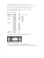
Parameter
AEG Mode
AEG R1 (Rate 1)
AEG R2 (Rate 2)
AEG L2 (Level 2)
AEG R3 (Rate 3)
AEG L3 (Level 3)
AEG R4 (Rate 4)
AEG RR (Release Rate)
E1 (Chorus)
nrm
30
37
59
28
54
0
30
E2 (Styroll)
nrm
63
12
50
30
47
10
30
19. When you get to this display:
It's time to learn a new technique.
The filter functions can be accessed by pressing the [ENTER] key from
the above display —just like it says on the screen. Once you're "in" the
filter function subset, you can move around using the [PAGE
and
[PAGE
keys just as you can anywhere else. When you're finished with
the filter function subset, return to the main function set by pressing the
[EXIT] key.
Of course you can also access any of the filter jobs by pressing the
[JOB] key and entering the appropriate job number.
The filter 1 or filter 2 envelope generator can be selected by holding
the [SELECT] key and pressing the numeric [9] or [6] key, respectively
(this operation will also take you directly to the filter functions from
anywhere within the voice edit mode).
Now that you're in the filter function subset; go ahead and program
the filter parameters, referring to the VeloChorus voice parameter chart on
page 40.
45
20. Next select job 40: Voice Name ("REFERENCE" section, page 89). Here
we'll give our original voice a name: "VeloChorus".
21. The VOICE Name job allows a name of up to 10 characters to be assigned
to the current voice. Use the
and
cursor keys to place the underline cursor under the character to be changed, then use the [DATA ENTRY]
control or [+1/YES] and [-1/NO] keys to select the desired character.
Continue until the entire voice name has been programmed.
22. Press [VOICE] to exit from the edit mode and return to the VOICE mode.
The reversed letter "E" that appears to the right of the voice number
indicates that the voice has been edited.
Caution!!: If you select a different voice or mode at this point, the edited
voice will be erased. To keep an edited voice, it must be stored to an
INTERNAL or CARD memory location, as described in the following
section. For a special method of recalling a voice lost in this way, see
"VOICE RECALL" on page 89.
Storing an Edited Voice
Now that you've created your first original voice — "VeloChorus" —
you'll want to store it to one of the SY55's 64 internal voice memory locations or a memory card location.
1. After exiting the edit mode by pressing the [VOICE] key, press the [STORE/
COPY] key. The following display will appear:
The voice number on the top line indicates the source setup — i.e. the
"VeloChorus" voice we just created in the SY55's edit buffer memory.
The voice number after the arrow on the bottom line is the target voice —
i.e. the memory location to which we will store the edited voice.
2. The target memory location can be changed by using the [DATA ENTRY]
control, [-1/NO] and [+1/YES] keys, or numeric and [ENTER] keys. The
[INTERNAL] and [CARD] keys can be used to change banks, if necessary
(obviously you can't store to the read-only PRESET bank, or to a card if
no card is loaded).
Note: If you intend to store the voice to a memory card, make sure that the
card has been properly formatted ("REFERENCE" section, page 138), and
that the card's WRITE PROTECT switch is turned OFF (refer to the
MCD64 or MCD32 Memory Card instructions for details).
46
TUTORIALS
3. When you're satisfied with the target memory location selection, press
[ENTER].
"Sure?" appears on the top line of the display, asking you to confirm
you intention to store to the selected target location. This confirmation
step is important because once you store, all previous data in the target
location is erased and completely replaced by the new data.
4. Press [+1/YES] to confirm and actually execute the store operation, or [-1/
NO] to cancel. "Executing!" will appear on the display during store, and
"Completed!" will appear briefly when the store operation is finished.
Your "VeloChorus" voice has now been stored and can be recalled
whenever needed!
Note: Refer to the "ERROR MESSAGES" section on page 144 for information on memory-card related error messages.
Conclusion
Well that's about it. You've learned the basics of getting around in the
SY55's play and edit modes. Be sure to read the "General Operation" sections
in the reference section for more important operating techniques. The voice
edit mode, for example, offers element, AEG and effect copy functions that
can make the job of programming voices much faster and more efficient.
If you've carefully gone through all five tutorials, you should now be able
to handle just about any SY55 job simply by referring to the reference section.
47
REFERENCE SECTION
Contents
GENERAL
OPERATION
. . . . . . . . . . . . . . . . . . . . . . . . . . . . . . . . . . . . . . . . . . . . 52
Selecting the Voice Edit Mode . . . . . . . . . . . . . . . . . . . . . . . . . . . . . . . . . . . . . . . . . . . . . 52
Selecting the Various Edit Mode Jobs . . . . . . . . . . . . . . . . . . . . . . . . . . . . . . . . . . . . . . . 52
Selecting and Editing Parameter Values . . . . . . . . . . . . . . . . . . . . . . . . . . . . . . . . . . . . . 53
Selecting an Element to Edit/Element ON-OFF Switching . . . . . . . . . . . . . . . . . . . . . . 54
Edit/Compare Operation . . . . . . . . . . . . . . . . . . . . . . . . . . . . . . . . . . . . . . . . . . . . . . . . . . . 54
The Element, AEG and Filter Copy Functions . . . . . . . . . . . . . . . . . . . . . . . . . . . . . . . . 55
The Effect Copy Function . . . . . . . . . . . . . . . . . . . . . . . . . . . . . . . . . . . . . . . . . . . . . . . . . 5 6
JOBS & PARAMETERS
. . . . . . . . . . . . . . . . . . . . . . . . . . . . . . . . . . . . . . . . . . . . . . . . . 58
VOICE MODE . . . . . . . . . . . . . . . . . . . . . . . . . . . . . . . . . . . . . . . . . . . . . . . . . . . . . . . . . . . 58
AWM WAVE SELECTION . . . . . . . . . . . . . . . . . . . . . . . . . . . . . . . . . . . . . . . . . . . . . . . . 5 8
VOLUME . . . . . . . . . . . . . . . . . . . . . . . . . . . . . . . . . . . . . . . . . . . . . . . . . . . . . . . . . . . . . . . 5 9
NOTE SHIFT . . . . . . . . . . . . . . . . . . . . . . . . . . . . . . . . . . . . . . . . . . . . . . . . . . . . . . . . . . . . 5 9
DETUNE . . . . . . . . . . . . . . . . . . . . . . . . . . . . . . . . . . . . . . . . . . . . . . . . . . . . . . . . . . . . . . . .60
LOW NOTE LIMIT . . . . . . . . . . . . . . . . . . . . . . . . . . . . . . . . . . . . . . . . . . . . . . . . . . . . . . . 60
HIGH NOTE LIMIT . . . . . . . . . . . . . . . . . . . . . . . . . . . . . . . . . . . . . . . . . . . . . . . . . . . . . . 61
LOW VELOCITY LIMIT . . . . . . . . . . . . . . . . . . . . . . . . . . . . . . . . . . . . . . . . . . . . . . . . . . 6 1
HIGH VELOCITY LIMIT . . . . . . . . . . . . . . . . . . . . . . . . . . . . . . . . . . . . . . . . . . . . . . . . . 6 2
PANNING . . . . . . . . . . . . . . . . . . . . . . . . . . . . . . . . . . . . . . . . . . . . . . . . . . . . . . . . . . . . . . . 6 2
EFFECT BALANCE . . . . . . . . . . . . . . . . . . . . . . . . . . . . . . . . . . . . . . . . . . . . . . . . . . . . . . 6 3
OSCILLATOR MODE/NOTE/TUNE . . . . . . . . . . . . . . . . . . . . . . . . . . . . . . . . . . . . . . . . 6 3
AMPLITUDE ENVELOPE GENERATOR (AEG) MODE/LEVEL/RATE . . . . . . . . 6 4
AMPLITUDE ENVELOPE GENERATOR (AEG) RATE SCALING . . . . . . . . . . . . . 6 6
AMPLITUDE ENVELOPE GENERATOR (AEG)
LEVEL SCALE BREAKPOINT . . . . . . . . . . . . . . . . . . . . . . . . . . . . . . . . . . . . . . . . . . . . 6 6
AMPLITUDE ENVELOPE GENERATOR (AEG) LEVEL SCALE OFFSET ..... 66
SENSITIVITY (VELOCITY, AMPLITUDE & PITCH MODULATION) . . . . . . . . . 6 7
LOW FREQUENCY OSCILLATOR (LFO)
WAVEFORM/SPEED/DELAY/PHASE . . . . . . . . . . . . . . . . . . . . . . . . . . . . . . . . . . . . . . 6 9
LOW FREQUENCY OSCILLATOR (LFO) MODULATION DEPTH,
AMPLITUDE/PITCH/CUTOFF . . . . . . . . . . . . . . . . . . . . . . . . . . . . . . . . . . . . . . . . . . . . 7 0
50
VOICE EDIT MODE
PITCH ENVELOPE GENERATOR (PEG) LEVEL/RATE . . . . . . . . . . . . . . . . . . . . . . 7 1
PITCH ENVELOPE GENERATOR (PEG) SENSITIVITY,
RANGE/RATE SCALING/VELOCITY SWITCH . . . . . . . . . . . . . . . . . . . . . . . . . . . . . 7 2
FILTER: TYPE/CUTOFF/MODE . . . . . . . . . . . . . . . . . . . . . . . . . . . . . . . . . . . . . . . . . . . 7 3
FILTER: CUTOFF ENVELOPE GENERATOR . . . . . . . . . . . . . . . . . . . . . . . . . . . . . . . 7 5
FILTER: RATE SCALING . . . . . . . . . . . . . . . . . . . . . . . . . . . . . . . . . . . . . . . . . . . . . . . 76
FILTER: LEVEL SCALING BREAKPOINT . . . . . . . . . . . . . . . . . . . . . . . . . . . . . . . . . 7 6
FILTER: LEVEL SCALING OFFSET . . . . . . . . . . . . . . . . . . . . . . . . . . . . . . . . . . . . . . . 77
FILTER: RESONANCE/VELOCITY SENSITIVITY/
MODULATION SENSITIVITY . . . . . . . . . . . . . . . . . . . . . . . . . . . . . . . . . . . . . . . . . . . . 77
ELEMENT INITIALIZE . . . . . . . . . . . . . . . . . . . . . . . . . . . . . . . . . . . . . . . . . . . . . . . . . . . 7 9
CONTROLLER: PITCH BEND RANGE ..................................... 81
CONTROLLER: AFTER TOUCH PITCH BIAS . . . . . . . . . . . . . . . . . . . . . . . . . . . . . . 81
CONTROLLER: RANDOM PITCH RANGE . . . . . . . . . . . . . . . . . . . . . . . . . . . . . . . . . 81
CONTROLLER: AMPLITUDE MODULATION . . . . . . . . . . . . . . . . . . . . . . . . . . . . . . 8 2
CONTROLLER: PITCH MODULATION ....................................82
CONTROLLER: CUTOFF MODULATION ..................................83
CONTROLLER: CUTOFF FREQUENCY CONTROL . . . . . . . . . . . . . . . . . . . . . . . . 83
CONTROLLER: EG BIAS CONTROL . . . . . . . . . . . . . . . . . . . . . . . . . . . . . . . . . . . . . . 8 4
CONTROLLER: VOLUME CONTROL . . . . . . . . . . . . . . . . . . . . . . . . . . . . . . . . . . . . . 8 4
EFFECT: TYPE/OUTPUT LEVEL . . . . . . . . . . . . . . . . . . . . . . . . . . . . . . . . . . . . . . . . . . 8 5
EFFECT: EFFECT PARAMETERS . . . . . . . . . . . . . . . . . . . . . . . . . . . . . . . . . . . . . . . . . 8 6
VOICE NAME . . . . . . . . . . . . . . . . . . . . . . . . . . . . . . . . . . . . . . . . . . . . . . . . . . . . . . . . . . . 89
VOICE RECALL . . . . . . . . . . . . . . . . . . . . . . . . . . . . . . . . . . . . . . . . . . . . . . . . . . . . . . . . . 89
VOICE INITIALIZE . . . . . . . . . . . . . . . . . . . . . . . . . . . . . . . . . . . . . . . . . . . . . . . . . . . . . . 9 0
51
Selecting the Voice Edit Mode
Press the [VOICE] key followed by the [EDIT/
COMPARE] key. Both the [VOICE] and [EDIT/COMPARE] key indicators should be lit.
You can exit the voice edit mode and return to
the voice play mode at any time by pressing either
the [VOICE] key or the [EXIT] key.
If the VOICE PLAY mode is already selected
(i.e. the [VOICE] key indicator is lit), it is only necessary to press the [EDIT/COMPARE] key.
Selecting the Various Edit Mode Jobs
Once the voice edit mode has been selected, two
different methods can be used to select the various
voice editing jobs.
"Filter" is selected, for example, "press ENTER"
will appear on the bottom line of the display.
Method 1: Page Access.
The [PAGE
and [PAGE
keys can be used
to scroll forward and backward through the editing
jobs.
To step forward through the voice edit
job list.
Hold for continuous scrolling.
To step backward through the voice edit
job list.
Hold for continuous scrolling.
In some cases a display screen accessed by the
[PAGE
and [PAGE
keys will actually be a
"doorway" to a separate list of jobs relating to that
function. In the voice edit mode, the FILTER, CONTROLLER and EFFECT jobs are of this type. When
52
When you press [ENTER], the [PAGE
and
[PAGE keys can be used to access a whole subset
of FILTER jobs. When you're finished editing filter
jobs, press the [EXIT] key to return to the primary
job list.
Method 2: Direct Job Number Entry.
All edit mode jobs have a "job number." These
are listed along with the job names throughout the
reference section of this manual. Any editing job
can be directly accessed by first pressing the [JOB]
key, and then selecting the desired job number using
the [DATA ENTRY] control, the [-1/NO] and [+1/
YES] keys, or the numeric and [ENTER] keys.
VOICE EDIT MODE
When the [JOB] key is pressed, the job selection
display appears showing the currently selected job.
On the upper display line "V.ED JOB 1—42"
means that you are in the voice edit mode (V.ED)
and that you have a choice of jobs 1 through 42
(JOB 1—42).
You can now select the desired job number by
using the [DATA ENTRY] control/the [-1/NO] and
[+1/YES] keys, or the numeric keys.
If you use the numeric keys, the entered number
will flash on the display. Confirm that the desired
job name appears on the display, then press the
[ENTER] key to go directly to the selected job.
Selecting and Editing Parameter Values
Some jobs only have a single parameter, while
others contain several that must be selected using
the
and
cursor keys. In many cases the
and
keys arc used to select one of the available
elements in a multi-element voice.
The value of a selected parameter is adjusted
using the [DATA ENTRY] control, the [-1/NO] and
[+1/YES] keys, or the numeric and [ENTER] keys.
When using the numeric keys, first enter the
desired value in one, two, or three digits (the value
will flash on the display), then press the [ENTER]
key (the value will stop flashing). In general, if you
enter a value higher than the maximum value or
lower than the minimum value for the selected parameter, the maximum or minimum value will be
selected, respectively, when the [ENTER] key is
pressed. The numeric [-] key can be used to make
positive values negative, and vice versa, for parameters which accept negative values.
To select desired element or parameter.
53
Selecting an Element to Edit/Element ON-OFF Switching
Although the
and
cursor keys are used to
select a particular element in many functions, some
functions that can be individually programmed for
each element contain several different parameters
keys, so
which must be selected using the and
an alternative means of element selection has been
provided.
If you press and hold the [SELECT] key the element selection and switching display will appear.
On the upper display line "FL1" indicates that
Filter 1 is selected and "EL1" indicates that Element
1 is selected. The lower display line indicates that
the 2-element mode has been selected (elements 1
and 2 are active). The asterisks (*) indicate elements that are not available (3 and 4 in this case).
While the [SELECT] key is held, any of the available elements can be selected by pressing the
corresponding [EL SEL] key (note the green markings next to the numeric [7], [4], [1] and [0] keys).
Also while the [SELECT] key is pressed, any of
the available elements can also be turned ON or
OFF (usually to hear how a single element in a
multiple-element voice sounds) by pressing the corresponding [EL ON/OFF] key (the numeric [8], [5],
[2] and [-] keys). An available element that has been
turned OFF in this manner appears as a "-" on the
display.
Releasing the [SELECT] key returns the display
to the current function.
Edit/Compare Operation
Normally, when you play a voice that is being
edited in the voice edit mode you hear the sound of
the edited voice. This can be compared with the
original (pre-edit) sound by pressing the [EDIT/
COMPARE] key to activate the COMPARE mode.
The [EDIT/COMPARE] key indicator will flash while
the COMPARE mode is active. Press the [EDIT/
COMPARE] key again to return to the VOICE EDIT
mode.
54
NOTE: While the COMPARE mode is active it is
not possible to select any other functions. The
[EXIT] key can be used, however, to return to the
voice play mode.
NOTE: When the compare function is used, the
contents of the TG55 "recall buffer" are replaced
with the current contents of the edit buffer (i.e.
the current status of the voice being edited).
This can affect the outcome of a VOICE RECALL operation — see "VOICE RECALL" on
page 77.
VOICE EDIT MODE
The Element, AEG and Filter Copy Functions
The Element, AEG and Filter Copy functions
make it possible to copy all parameter assignments,
just the AEG parameter assignments, or just the filter parameter assignments from any other element to
the element currently being edited. This is useful if,
for example, you want to create an AEG curve that
is the same as, or varies only slightly from, one that
already exists.
1. Make sure the voice edit mode is engaged and
that any function other than one of the EFFECT,
AEG or FILTER functions is selected if you
want to copy all element parameters, that one of
the AEG functions is selected if you want to
copy the AEG parameters, or that one of the
FILTER functions is selected if you want to copy
the filter parameters.
2. Select the element to which the new parameter
data will be copied using the standard element
selection procedure described above.
3. Press the [STORE/COPY] key. One of the following displays will appear, depending on the currently selected function.
5. Move the underline cursor to the element parameter to the right by pressing the
key,
then choose the particular element of the selected voice you want to copy the data from
using the [DATA ENTRY] control or [+1/YES]
and [-1/NO] keys.* If the element number appears in reverse, the voice does not use that
element and no data is available.
* For Filter Copy, the "editbuf" setting allows
copying parameters from filter 1 to filter 2, or
vice versa, when copying within the same element (e.g. EL1 EL1). In this case, the filter
to be copied to must be selected prior to
pressing [STORE/COPY] key by holding the
[SELECT] key and pressing either the numeric
[9] or [6] key. "F2 F1" or "F1 F2" will appear on the upper line of the display to show
the selected copy direction.
6. When the elements to and from which the data is
to be copied have been properly selected, press
the [ENTER] key. "Sure?" will appear on the top
line of the LCD.
4. Next, select the voice from which the parameter
data is to be copied by using the [DATA ENTRY]
control, [-1/NO] and [+1/YES] keys, or numeric
and [ENTER] keys. "editbuf" refers to the voice
that is currently being edited, and other voices
can be selected by using standard procedure —
[INTERNAL], [CARD], or [PRESET] key to select
voice bank; [DATA ENTRY] control, [-1/NO] and
[+1/YES] keys, or numeric and [ENTER] keys to
select the voice.
7. Press the [+1/YES] key to confirm and actually
execute the copy operation, or [-1/NO] to cancel.
"Executing! will appear briefly on the display
while the data is being copied, then "Completed!" will appear for a few seconds when the
copy operation has been successfully completed.
55
8. When the copy operation has finished, the SY55
will return automatically to. the display that was
showing immediately prior to activation of the
element copy function.
The Effect Copy Function
The Effect Copy function makes it possible to
copy the effect parameter assignments from any
other voice or multi-timbral setup to the voice currently being edited.
5. Press the [ENTER] key. "Sure?" will appear on
the top line of the LCD.
1. Make sure the voice edit mode is engaged and
that one of the EFFECT functions is selected.
2. Press the [STORE/COPY] key. The following display will appear.
6. Press the [+1/YES] key to confirm and actually
execute the copy operation, or [-1/NO] to cancel.
"Executing! will appear briefly on the display
while the data is being copied, then "Completed!" will appear for a few seconds when the
copy operation has been successfully completed.
and
cursor keys to move to the
3. Use the
Multi/Voice parameter and select "Multi" if you
want to copy the effect parameters from a multitimbral setup, or "Voice" if you want to copy the
effect parameters from a preset or internal voice.
4. Next, move the cursor to the multi or voice number parameter by pressing the
key, and select the multi-timbral setup or voice from which
the parameter data is to be copied by using the
[DATA ENTRY] control, [-1/NO] and [+1/YES]
keys, or numeric and [ENTER] keys. The [INTERNAL], [CARD], or [PRESET] key can be used to
select the "P" (preset) or "I" voice bank if necessary.
56
7. When the copy operation has finished, the SY55
will return automatically to the display that was
showing immediately prior to activation of the
effect copy function.
VOICE EDIT MODE
57
VOICE MODE
Summary: Determines whether the voice will be a
1-element (max. 16-note polyphony), 2-element
(max. 8-note polyphony) or 4-element (max. 4note polyphony) type.
Settings: 1 Element, 2 Element, 4 Element.
Procedure: The [DATA ENTRY] control or [+1/YES]
and [-1/NO] keys are used to select the desired
number of elements.
Details: The number of elements used in a voice basically determines the number of different waveforms that can be played simultaneously: one
waveform in the 1-element mode, two waveforms in the 2-element mode, and four waveforms in the 4-element mode. Since each individual element has its own waveform, filters,
envelope generator, etc., the waveforms in a
multi-element voice can be combined in several
JOB 1
different ways. They can simply be played simultaneously, limited to specific regions of the
keyboard to create a "split keyboard" voice, one
waveform could be used only for the attack portion of the voice while another is used for the
sustain, and so on.
When selecting the 2- or 4-element mode,
always keep in mind the fact that these modes
reduce the number of notes you can play at the
same time:
Mode
Polyphony
1-element mode:
2-element mode:
4-element mode:
16 notes
8 notes
4 notes
The tutorial goes into further detail concerning the use of the multi-element modes.
Refer to: Tutorial, page 35...37, 42.
AWM WAVE SELECTION
Summary: Assigns a preset or card wave to each
active voice element.
Settings:
P01 ... P58 (preset voices)
P59 ... P74 (preset drums)
C01 ... max. C99 (card voices)
Procedure: When the 1-element mode is selected
(as in the example LCD display, above), only a
single wave may be assigned. The unavailable
elements are each represented by "***" on the
display.
58
If the 2- or 4-element mode is selected, different waves may be assigned to each available
cursor keys are used
element. The
and
to move the cursor to the desired element (EL1,
EL2, EL3 or EL4 will appear in the upper righthand comer of the display), and the [DATA ENTRY] control, [-1/NO] and [+1/YES] keys, or
numeric and [ENTER] keys are used to assign the
desired wave to the selected element. The wave
number (P01... P74, C01... C99) is shown at the
current cursor location, and the full name of the
assigned wave is shown in the upper left-hand
corner of the display.
Details: Completely different waves can be assigned
to each element, but it is also possible to assign
the same wave to different elements. In this case
VOICE EDIT MODE
the waves can be filtered differently and/or have
different envelopes to create an endless range of
interesting effects.
Refer to: Tutorial, page 35, 42.
VOLUME
JOB 3
and [+1/YES] keys, or numeric and [ENTER] keys
are used to set the desired volume.
Summary: Allows individual adjustment of element
volume as well as overall (total) volume adjustment.
Settings: 0 ... 127
Procedure: The
and
cursor keys are used
to select the element for which the volume is to
be adjusted, or overall "Total" volume control
(EL1, EL2, EL3, EL4 or Total will appear in the
upper right-hand comer of the display). Unavailable elements are represented by "***" on the
display. The [DATA ENTRY] control, [-1/NO]
Details: A setting of "0" produces no sound while a
setting of "127" produces maximum volume.
The ability to independently adjust the volume of each element makes it simple to set up
the optimum balance or "mix" between elements. Overall volume adjustment can be used
to match the the overall level of different voices.
Refer to: Tutorial, page 42.
NOTE SHIFT
Summary: Individually shifts the pitch of each active element up or down in semitone steps.
Settings: -64 ... +63.
Procedure: The
and
cursor keys are used
to select the element to be note-shifted (EL1,
EL2, EL3 or EL4 will appear in the upper righthand comer of the display). Unavailable elements are represented by "***" on the display. The [DATA ENTRY] control, [-1/NO] and
(+1/YES] keys, or numeric and [ENTER] keys are
used to set the desired degree of note shift.
JOB 4
Details: A setting of "-12," for example, shifts the
pitch of the selected element down by one octave; a setting of "+4" shifts the pitch up by a
major third.
The Note Shift function can be used to transpose a voice to its most useful range, or to create
harmony (intervals) between different elements
in a multi-element voice.
Refer to: Utility mode "TRANSPOSE," page 132.
59
DETUNE
Summary: Allows slight upward or downward pitch
adjustment of each active element.
Settings: -7 ... +7
Procedure: The
and
cursor keys are used
to select the element to be detuned (EL1, EL2,
EL3 or EL4 will appear in the upper right-hand
comer of the display). Unavailable elements are
represented by "***" on the display. The
[DATA ENTRY] control, [-1/NO] and [+1/YES]
keys, or numeric and [ENTER] keys are used to
set the desired degree of detuning.
Details: The maximum minus setting of "-7" produces a downward pitch shift of approximately a
quarter of a semitone, and the maximum plus
setting of "+7" produces an upward pitch shift
of approximately the same amount. A setting of
"0" produces no pitch change.
The Detune function allows different elements in a multi-element voice to be slightly
detuned in relation to each other, thereby "thickening" the overall sound.
Refer to: "OSCILLATOR MODE/NOTE/TUNE,"
page 63.
LOW NOTE LIMIT
Summary: Individually sets the low note limit for
each active element (the lowest note that each
element will produce).
Settings: C-2 ... G8
Procedure: The
and
cursor keys are used
to select the element for which the low note
limit is to be set (EL1, EL2, EL3 or EL4 will
appear in the upper right-hand comer of the display). Unavailable elements are represented by
"***" on the display. The [DATA ENTRY]
control or [+1/YES] and [-1/NO] keys are used to
set the low note limit.
The low note limit can also be set by pressing the [ENTER] key — "KBD" will flash on the
display — and then the key on the keyboard corresponding to the desired low note.
Details: The C-2 to G8 range of this function covers a full 10-1/2 octaves. "C3" corresponds to
"middle C" on a keyboard.
This function, in conjunction with the High
60
JOB 5
JOB 6
Note Limit function described below, allows the
sound from an element to be limited to a specific
region of the keyboard (or scale of other types
of MIDI controllers). If the Low Note Limit is
set to C3 and the High Note Limit for the same
element is. set to C4, for example, the sound
from that element will only be produced between
C3 and C4 — the octave immediately above
middle C. This makes it simple to produce split
voices.
If the High Note Limit is set to a note that is
lower than the Low Note Limit for the same
element, the full range of notes (C-2...G8) will
be produced.
Refer to: Tutorial, page 36. "HIGH NOTE LIMIT"
on page 61.
VOICE EDIT MODE
HIGH NOTE LIMIT
JOB 7
The high note limit can also be set by pressing the [ENTER] key — "KBD" will flash on the
display — and then the key on the keyboard corresponding to the desired high note.
Summary: Individually sets the high note limit for
each active element (the highest note that each
element will produce).
Details: See "LOW NOTE LIMIT," above.
Refer to: Tutorial, page 36. "LOW NOTE LIMIT"
on page 60.
Settings: C-2 ... G8
Procedure: The
and
cursor keys are used
to select the element for which the high note
limit is to be set (EL1, EL2, EL3 or EL4 will
appear in the upper right-hand comer of the display). Unavailable elements are represented by
"***" on the display. The [DATA ENTRY]
control or [+1/YES] and [-1/NO] keys are used to
set the high note limit.
LOW VELOCITY LIMIT
Summary: Sets the lowest velocity value for a range
of velocity values over which each active element will produce output.
Settings: 1 ... 127
Procedure: The
and
cursor keys are used
to select the element for which the low velocity
limit is to be set (EL1, EL2, EL3 or EL4 will
appear in the upper right-hand comer of the display). Unavailable elements are represented by
"***" on the display. The [DATA ENTRY]
control, [-1/NO] and [+1/YES] keys, or numeric
and [ENTER] keys are used to set the low velocity limit.
The low velocity limit can also be set by
pressing the [ENTER] key — "KBD" will flash
on the display — and then a key on the keyboard
at approximately the desired velocity.
JOB 8
troller) contains a "velocity" value that tells the
tone generator how hard the note has been
played. The range, of MIDI velocity values is
from 1 to 127— thus the 1 ... 127 range of this
function.
The Low Velocity Limit function, in conjunction with the High Velocity Limit function
described below, makes it possible to specify a
range of velocity values over which the selected
element will produce sound. You could, for example, set Low Velocity Limit to "60" and High
Velocity Limit to "127." This would cause that
element to produce output only when a velocity
value between 60 and 127 was received — i.e.
when a fairly loud note is played. A second
element could then be set to produce output only
when velocity values below 60 are received, so
that completely different sounds are produced
on soft and loud notes.
Refer to: Tutorial, page 43. "HIGH VELOCITY
LIMIT" on page 62.
Details: Every MIDI "NOTE ON MESSAGE" (the
MIDI message that is transmitted every time a
note is played on a keyboard or other MIDI con61
HIGH VELOCITY LIMIT
Summary: Sets the highest velocity value for a
range of velocity values over which each active
element will produce output.
Settings: 1 ... 127
Procedure: The
and
cursor keys are used
to select the element for which the high velocity
limit is to be set (EL1, EL2, EL3 or EL4 will
appear in the upper right-hand comer of the display). Unavailable elements are represented by
"***" on the display. The [DATA ENTRY]
control, [-1/NO] and [+1/YES] keys, or numeric
and [ENTER] keys are used to set the high velocity limit.
The high velocity limit can also be set by
pressing the [ENTER] key — "KBD" will flash
on the display — and then a key on the keyboard
at approximately the desired velocity.
Details: See "LOW VELOCITY LIMIT," above.
Refer to: Tutorial, page 43. "LOW VELOCITY
LIMIT" on page 61.
PANNING
Summary: Determines the position in the stereo
sound field in which the sound from each active
element will be heard (left to right).
Settings: -31 ...+31
Procedure: The
and
cursor keys are used
to select the element for which the pan position
is to be set (EL1, EL2, EL3 or EL4 will appear
in the upper right-hand corner of the display).
Unavailable elements are represented by
"***" on the display. The [DATA ENTRY]
control, [-1/NO] and [+1/YES] keys, or numeric
and [ENTER] keys arc used to set the pan position.
The upper line of the display also shows a
graphic representation of the stereo sound field
with "L" representing "left" and "R" representing "right." As you change the pan value the
vertical bar will appear at the corresponding
position on the graphic display.
62
JOB 9
JOB 10
Details: Minus values represent panning to the left,
and positive values represent panning to the
right. "0" positions the sound of the selected
element in the center of the stereo sound field.
For a single-element voice the Pan position
should generally be set to center ("0") unless
you have some specific reason why you want the
sound to appear only at the L/MONO or R output jack. In multi-element voices interesting stereo effects can be produced by placing the output from different elements at different locations in the stereo sound field.
Refer to: "THE CONTROLS AND CONNECTORS," page 7.
VOICE EDIT MODE
EFFECT BALANCE
Summary: Determines the balance between the direct and effect sound for each active element.
Settings: 0 ... 100
Procedure: The
and
cursor keys are used
to select the element for which the effect balance is to be set (EL 1, EL2, EL3 or EL4 will
appear in the upper right-hand comer of the display). Unavailable elements are represented by
" * * * " on the display. The [DATA ENTRY]
control, [-1/NO] and [+1/YES] keys, or numeric
and [ENTER] keys are used to set the effect balance.
Details: A setting of "0" produces only the direct
sound of the selected element, while a setting of
"100" produces only the effect sound. A setting
of "50" delivers both the direct and effect sound
in approximately equal proportions.
The effect (reverb, delay, etc.) applied to the
voice is selected and edited using the EFFECT
functions described on page 86.
Refer to: Tutorial, page 43. "EFFECT: TYPE/OUTPUT LEVEL" on page 85. "EFFECT: EFFECT
PARAMETERS" on page 86. Utility mode "EFFECT" on page 133.
OSCILLATOR MODE/NOTE/TUNE
Frequency Mode
Summary: Determines whether the AWM wave for
the selected element is reproduced in the normal
(variable pitch) or fixed-pitch mode.
Settings: norm, fix
Procedure: If the Frequency Mode ("Frq.Mode" on
upper LCD line) parameter is not already selected, use the
and
cursor keys to select
it. Use the [DATA ENTRY] control or [+1/YES]
and [-1/NO] keys to select the "fix" or "norm"
setting.
JOB 1 2
JOB 1 2
Details: Normally you want the pitch of the AWM
wave (or waves) used in a voice to be controllable from a keyboard or other type of controller, so this parameter will be set to "norm" for
most applications.
In some cases — sound effects in particular
— you might want the same pitch to be produced no matter what note you play on the keyboard or other controller. In this case, the "fix"
mode is appropriate. The Frequency Note parameter described below can be used to set the
note produced when the "fix" mode is selected.
63
Frequency Note
Summary: Sets the frequency (note) of the AWM
wave for the selected element when the "fix"
mode (above) is selected.
Settings: C-2 ... G8
Procedure: The "Frq.Note" parameter only appears
when the "Frq.Mode" parameter described above
has been set to "fix."
Frequency Tune
Summary: Allows tuning of the AWM wave assigned to the selected element.
Settings: -64 ... +63
cursor keys to
Procedure: Use the
and
select the Frequency Tune ("Frq.Tune") parameter. Use the [DATA ENTRY] control, [-1/NO] and
[+1/YES] keys, or numeric and [ENTER] keys to
set the tuning as required.
and
cursor keys to select
Use the
the Frequency Note ("Frq.Note") parameter. Use
the [DATA ENTRY] control or [+1/YES] and [-1/
NO] keys to select the desired note.
The frequency note can also be set by pressing the [ENTER] key — "KBD" will flash on the
display — and then the key on your keyboard
corresponding to the desired note.
Details: The C-2 to G8 range of this parameter
covers a full 10-1/2 octaves. "C3" corresponds
to "middle C" on a keyboard.
Refer to: "NOTE SHIFT," page 59.
Details: Each tuning increment corresponds to a 75/
64-cent change in pitch. The entire tuning range
is therefore 75/64 x 127 (i.e. 64 + 63 increments) — almost 150 cents. Since 100 cents
equals one semitone, the tuning range is approximately one and a half semitones. A setting of
"0" produces normal pitch (A3 = 440 Hertz).
Please note that this parameter is used to individually tune different elements within a
voice. Overall tuning control is provided by the
MASTER tune function in the UTILITY mode.
Refer to: "MASTER TUNE" on page 132.
"DETUNE" on page 60.
AMPLITUDE ENVELOPE GENERATOR (AEG)
MODE/LEVEL/RATE
Summary: All the parameters within this function
determine the "shape" of the amplitude envelope
of the selected element.
Settings:
Mode parameter: nrm, hld
R1/HT, R2, L2, R3, L3, R4 and RR parameters:
0 ... 63
64
JOB 13
Procedure: If the Mode ("Mode" on upper LCD
line) parameter is not already selected, use the
and
cursor keys to select it, then use
the [DATA ENTRY] control, [-1/NO] and [+1/
YES] keys to select the "nrm" (normal) or "hld"
(hold) setting. Once the desired mode has been
selected, use the
and
cursor keys to
select the various rate and level parameters in
turn (R1/HT, R2, L2, R3, L3, R4 and RR), using
the [DATA ENTRY] control or [+1/YES] and [-1/
NO] keys, or numeric and [ENTER] keys to set
the value of each. "R1" (Rate 1) will appear
VOICE EDIT MODE
when the "nrm" mode has been selected, but
"HT (Hold Time) will appear instead when the
"hld" mode is selected.
The arrow symbols ( and )that appear at
either end of the display mean that more parameters can be accessed by moving the cursor in
the indicated direction using the
and
keys.
Details:
The "nrm" and "hld" mode settings affect the
initial attack of the sound, determining how the
amplitude envelope begins. In the "nrm" mode,
the envelope begins from zero level, reaching
the maximum AWM level at a rate determined
by the R1 (Rate 1) parameter. In this mode there
will always be a slight delay between the initiation of a note and maximum level. The following two diagrams show the kind of envelopes
that can be produced in the "nrm" mode.
If the "hld" mode is selected, the envelope
begins immediately from maximum AWM level,
allowing the fast attack transients of waveforms
to pass unaffected. In this case the R1 parameter
is replaced by the HT (Hold Time) parameter.
The HT parameter determines the length of time
between the beginning of the envelope and the
point at which the envelope begins to move towards L2 (Level 2) at R2 (Rate 2), as shown
below.
For the level parameters, a setting of "0"
corresponds to the lowest possible level (no
sound) while a setting of "63" produces the highest output level. A "0" rate parameter setting
produces the slowest rate between levels, while
the maximum setting of "63" produces the fastest (almost instantaneous) change.
Refer to: Tutorial, page 36, 44.
The envelop begins at zero level, reaches
maximum level at the rate determined by the Rl
parameter, moves to L2 (Level 2) at R2 (Rate 2),
moves on to L3 (Level 3) at R3 (Rate 3), and
finally decays to zero level at R4 (Rate 4) if the
note is held the entire time.
If the note is released before the end of the
envelope described above, then the sound decays to zero level from the point at which the
note is released at the rate determined by the RR
(Release Rate) parameter.
65
AMPLITUDE ENVELOPE GENERATOR (AEG) RATE SCALING
Summary: Allows the overall amplitude envelope
generator decay rate for the selected element to
be varied across the entire pitch range.
Settings: -7 ... +7
Procedure: Use the [DATA ENTRY] control, [-1/
NO] and [+1/YES] keys, or numeric and [ENTER]
keys to set the desired degree of rate scaling.
JOB 14
velope time for the high notes. This is useful for
simulating instruments such as piano, in which
the low notes take much longer to decay than the
high notes. The maximum "+7" setting produces
the greatest envelope length variation across the
pitch range. Minus ("-") settings produce the
opposite effect — short low notes and long high
notes. A setting of "+0" results in no envelope
length variation.
Refer to: "AMPLITUDE ENVELOPE GENERATOR (AEG) MODE/LEVEL/RATE," page 64.
Details: Plus ("+") settings produce a longer overall
envelope time for the low notes and a shorter en-
AMPLITUDE ENVELOPE GENERATOR (AEG)
LEVEL SCALE BREAKPOINT
JOB 1 5
The breakpoint can also be set by pressing
the [ENTER] key — "KBD" will flash on the
display — and then the key on the keyboard corresponding to the desired breakpoint.
Summary: Allows four separate amplitude envelope generator level-scaling breakpoints to be
set at any notes between C-2 and G8 for the
selected element.
Settings: C-2 ... G8
Procedure: Use the
and
cursor keys to
select the desired breakpoint (BP1, BP2, BP3
and BP4, from left to right), then use the [DATA
ENTRY] control or [+1/YES] and [-1/NO] keys to
set the breakpoint note.
Details: Level scale offset values arc applied to
each of the breakpoints using the LEVEL
SCALE OFFSET function described below.
Natural level variations can thereby be produced
across the range of the controlling keyboard. No
breakpoint can be set to a key lower than the
breakpoint to its left.
Refer to: "AMPLITUDE ENVELOPE GENERATOR (AEG) LEVEL SCALE OFFSET" below.
AMPLITUDE ENVELOPE GENERATOR (AEG) LEVEL SCALE OFFSET
Summary: Sets the amount of level offset for each
of the four level-scaling breakpoints set in the
"AMPLITUDE ENVELOPE GENERATOR
66
JOB 16
(AEG) LEVEL SCALE BREAKPOINT" function described above.
Settings: -127 ... +127
Procedure: Use the
and
cursor keys to
select the desired offset parameter (OFS1, OFS2,
OFS3 and OFS4, from left lo right), then use the
VOICE EDIT MODE
[DATA ENTRY] control, [-1/NO] and [+1/YES]
keys/or numeric and [ENTER] keys to set the
level-scaling offset for the corresponding breakpoint.
Refer to: "AMPLITUDE ENVELOPE GENERA-
TOR (AEG) LEVEL SCALE BREAKPOINT"
on page 66.
Details: Negative values reduce the level, and positive values increase the level at the corresponding breakpoint. No matter what value is chosen,
the EG level will never exceed its maximum of
63.
When different offsets are set for adjacent
breakpoints, the level varies accordingly and
smoothly between the breakpoints.
SENSITIVITY (VELOCITY, AMPLITUDE & PITCH MODULATION)
Velocity Sensitivity
Summary: Determines how the output level of the
selected element changes in response to velocity
changes (e.g. keyboard dynamics).
Settings: -7 ... +7
Procedure: If the Velocity Sensitivity ("Vel." on
upper LCD line) parameter is not already selected, use the
and
cursor keys to select
it. Use the [DATA ENTRY] control, [-1/NO] and
Velocity Rate Sensitivity ON/OFF
Summary: Determines whether overall envelope
length of the amplitude envelope generator for
the selected element will or will not be controlled by velocity information.
JOB 17
[+1/YES] keys, or numeric and [ENTER] keys to
select the required degree of velocity sensitivity.
Details: Plus "+" settings produce higher output
level in response to higher velocity values —
i.e. the harder a key is played, the louder the
sound. The maximum setting of "+7" produces
the maximum level variation in response to velocity changes. Minus "-" settings produce the
opposite effect: lower level in response to higher
velocity. A setting of "+0" results in no level
variation. Make sure that the volume is turned
down when making "-" settings, or you may not
be able to hear the full effect.
("V.Rate"). Use the [DATA ENTRY] control or
[+1/YES] and [-1/NO] keys to select "on" or
"off."
Details: When this parameter is turned "on," higher
velocity values produce a faster attack rate.
When "off no envelope rate variation is produced.
Refer to: "AMPLITUDE ENVELOPE GENERATOR (AEG) MODE/LEVEL/RATE," page 64.
Settings: on, off
Procedure: Use the
and
cursor keys to
select the Velocity Rate Sensitivity parameter
67
Amplitude Modulation Sensitivity
Summary: Determines the sensitivity of the selected element to amplitude modulation (tremolo effect) applied via the low-frequency oscillator (LFO) and appropriate controllers.
Settings: -7 ... +7
Procedure: Use the
and
cursor keys to
select the Amplitude Modulation Sensitivity
parameter ("AMS"). Use the [DATA ENTRY]
control, [-1/NO] and [+1/YES] keys, or numeric
and [ENTER] keys to set the required degree of
amplitude modulation sensitivity.
Pitch Modulation Sensitivity
Summary: Determines the sensitivity of the selected element to pitch modulation (vibrato effects) applied via appropriate controllers.
Settings: 0 ... 7
Procedure: Use the
and
cursor keys to
select the Pitch Modulation Sensitivity parameter ("PMS"). Use the [DATA ENTRY] control,
[-1/NO] and [+1/YES] keys, or numeric and [ENTER] keys to set the required degree of pitch
modulation sensitivity.
68
Details: A setting of "0" allows no amplitude modulation by any means, while a setting of "+7"
results in maximum sensitivity to amplitude
modulation. Minus settings produce reverse EG
bias — i.e. a higher modulation value produces
lower level.
When setting up the low-frequency oscillator or a controller to apply amplitude modulation, this parameter must be set to a value other
than "0" for amplitude modulation to take place.
Refer to: "LOW FREQUENCY OSCILLATOR
(LFO) WAVEFORM/SPEED/DELAY/PHASE"
on page 69. "LOW FREQUENCY OSCILLATOR MODULATION DEPTH, AMPLITUDE/
PITCH/CUTOFF" on page 70. "CONTROLLER" functions from page 81 to page 84.
Details: A setting of "0" allows no pitch modulation
by any means, while a setting of 7 results in
maximum sensitivity to amplitude modulation.
When setting up the low-frequency oscillator or a controller to apply pitch modulation,
this parameter must be set to a value other than
"0" for pitch modulation to take place.
Refer to: "LOW FREQUENCY OSCILLATOR
(LFO) WAVEFORM/SPEED/DELAY/PHASE"
on page 69. "LOW FREQUENCY OSCILLATOR MODULATION DEPTH, AMPLITUDE/
PITCH/CUTOFF" on page 70. "CONTROLLER" functions from page 81 to page 84.
VOICE EDIT MODE
LOW FREQUENCY OSCILLATOR (LFO)
WAVEFORM/SPEED/DELAY/PHASE
Wave
JOB 1 8
Details:
"tri" = Triangle.
"dwn" = Downward sawtooth.
"up" = Upward sawtooth.
"squ" = Square.
"sin" = Sine.
Summary: Determines the waveform of the LFO
for the selected element.
Settings: tri, dwn, up, squ, sin, S/H
"S/H" = Sample and hold.
Refer to: "SENSITIVITY (VELOCITY, AMPLITUDE & PITCH MODULATION," page 67.
Procedure: If the Wave parameter is not already
cursor keys to seselected, use the
and
lect it. Use the [DATA ENTRY] control or [+1/
YES] and [-1/NO] keys to select the desired LFO
waveform.
Speed
Summary: Sets the speed of the LFO for the selected element.
TRY] control, [-1/NO] and [+1/YES] keys, or
numeric and [ENTER] keys to set the desired
LFO speed.
Details: "0" produces the slowest LFO speed, and
"99" produces the fastest LFO speed.
Refer to: "SENSITIVITY (VELOCITY, AMPLITUDE & PITCH MODULATION," page 67.
Settings: 0 ... 99
and
cursor keys to
Procedure: Use the
select the Speed parameter. Use the [DATA EN-
Delay
Summary: Sets the delay time between the beginning of a note and the beginning of LFO operation for the selected element.
TRY] control, [-1/NO] and [+1/YES] keys, or
numeric and [ENTER] keys to set the desired LFO
delay.
Details: The minimum setting of "0" results in no
delay, while the maximum setting of "99" produces the longest possible delay before the LFO
begins operation.
Refer to: "SENSITIVITY (VELOCITY, AMPLITUDE & PITCH MODULATION," page 67.
Settings: 0 ... 99
Procedure: Use the
and
cursor keys to
select the Delay parameter. Use the [DATA EN69
Phase
TRY] control, [-1/NO] and [+1/YES] keys, or
numeric and [ENTER] keys to set the desired LFO
phase.
Settings: 0 ... 99
Details: If the LFO is used for pitch modulation, for
example, a phase setting of "0" would cause the
vibrato effect to begin with an upward pitch
sweep, while a setting of "55" would cause the
vibrato to begin with a downward pitch sweep.
The change can be subtle, and experimentation
is the best way to find the best setting.
Procedure: Use the
and
cursor keys to
select the Phase parameter. Use the [DATA EN-
Refer to: "SENSITIVITY (VELOCITY, AMPLITUDE & PITCH MODULATION," page 67.
Summary: Determines at which point in the LFO
waveform the LFO will begin operation for the
selected element.
LOW FREQUENCY OSCILLATOR MODULATION DEPTH,
AMPLITUDE/PITCH/CUTOFF
Amplitude Modulation Depth
Summary: Determines the amount of amplitude
modulation applied to the selected element.
Settings: 0 ... 127
Procedure: If the Amplitude Modulation
("AMOD") parameter is not already selected,
use the
and
cursor keys to select it. Use
the [DATA ENTRY] control, [-1/NO] and [+1/YES]
keys, or numeric and [ENTER] keys to set the
desired degree of amplitude modulation.
Pitch Modulation Depth
Summary: Determines the amount of pilch modulation applied to the selected element.
Settings: 0 ... 127
70
JOB 1 9
Details: A "0" setting produces no modulation while
a setting of "127" produces maximum modulation. Amplitude modulation produces a periodic
variation in the volume of the sound, thus creating a tremolo effect.
Please note that the amplitude modulation
sensitivity parameter (see page 68) must also be
set to an appropriate value before amplitude
modulation can be applied.
Refer to: "Amplitude Modulation Sensitivity" on
page 68.
Procedure: Use the
and
cursor keys to
select the Pitch Modulation ("PMOD") parameter. Use the [DATA ENTRY] control or [+1/YES]
and [-1/NO] keys, or numeric and [ENTER] keys
to set the desired degree of pitch modulation.
Details: A "0" setting produces no modulation while
a selling of "127" produces maximum modulation. Pitch modulation produces a periodic pitch
variation, thereby creating a vibrato effect.
VOICE EDIT MODE
Please note that the pitch modulation sensitivity parameter (see page 68) must also be set
to an appropriate value before pitch modulation
can be applied.
Refer to: "Pitch Modulation Sensitivity" on page
68.
Filter Cutoff Modulation Depth
Details: A "0" setting produces no modulation while
a setting of "127" produces maximum modulation. Filter cutoff modulation produces wah-wah
type effects.
Please note that the filter cutoff modulation
sensitivity parameter (see page 78) must also be
set to an appropriate value before cutoff frequency modulation can be applied.
Summary: Determines the amount of modulation
applied to the cutoff frequency of the filter of
the selected element.
Settings: 0 ... 127
Procedure: Use the
and
cursor keys to
select the Filter Cutoff Modulation ("CutofMOD") parameter. Use the [DATA ENTRY]
control, [-1/NO] and [+1/YES] keys, or numeric
and [ENTER] keys to set the desired degree of
cutoff modulation.
Refer to: Tutorial, page 37. "FILTER: RESONANCE/VELOCITY SENSITIVITY/MODULATION SENSITIVITY" on page 77.
PITCH ENVELOPE GENERATOR (PEG) LEVEL/RATE
Summary: All parameters within this function determine the "shape" of the pitch envelope generator for the selected element.
Settings:
L0, L1, L2, L3, and RL parameters: -64 ... +63
R1, R2, R3 and RR parameters: 0 ... 63
and
cursor keys to
Procedure: Use the
select the various rate and level parameters in
turn (L0, Rl, L1, R2, L2, R3, L3, RR and RL),
using the [DATA ENTRY] control, [-1/NO] and
[+1/YES] keys, or numeric and [ENTER] keys to
set the value of each.
The arrow symbols ( and )that appear at
either end of the display mean that more parameters can be accessed by moving the cursor in
the indicated direction using the
and
keys.
JOB 20
Details: Unlike the amplitude envelope generator,
the "Level" parameters of which actually correspond to volume levels, the pitch envelope generator level parameters correspond to pitch. Plus
"+" values produce higher pitch while minus
"-" values produce lower pitch. "0" level values
produce normal pitch.
The "Rate" parameters work in the same way
as the amplitude envelope generator rate parameters: a setting of "0" produces the slowest
rate between levels, while the maximum setting
of "63" produces the fastest (almost instantaneous) change.
The pitch envelope begins at L0 (Level 0),
moves to L1 (Level 1) at a rate determined by
the setting of R1, then to L2 (Level 2) at R2
(Rate 2), and then to L3 (Level 3) at R3 (Rate 3).
The pitch stays at L3 until the key is released,
and then moves to RL (Release Level) at the rate
determined by RR (Release Rate).
71
PITCH ENVELOPE GENERATOR SENSITIVITY,
RANGE/RATE SCALING/VELOCITY SWITCH
PEG Range
Summary: Sets the maximum range of pitch envelope generator pitch variation.
JOB 21
Details: This parameter determines the total maximum range of the pitch envelope generator, so a
setting of "2oct" means that the maximum range
is ±1 octave. That is, if a level parameter is set
to +63, for example, the pitch at that point will
be one octave above normal pitch.
Refer to: "PITCH ENVELOPE GENERATOR
(PEG) LEVEL/RATE," page 71.
Settings: 2oct, 1oct, 1/2oct
Procedure: If the Range parameter is not already
and
cursor keys to
selected, use the
select it. Use the [DATA ENTRY] control or [+1/
YES] and [-1/NO] keys to select the desired
range.
PEG Rate Scaling
Summary: Allows the overall pitch envelope generator rate for the selected element to be varied
across the entire pitch range.
Settings: -7 ... +7
Procedure: Use the
and
cursor keys to
select the Rate Scaling ("R.Scale") parameter.
Use the [DATA ENTRY] control, [-1/NO] and [+1/
YES] keys, or numeric and [ENTER] keys to set
the desired degree of rate scaling.
72
Details: Plus ("+") settings produce a longer overall
envelope time for the low notes and a shorter envelope time for the high notes. The maximum
"+7" setting produces the greatest envelope
length variation across the pitch range. Minus
("-") settings produce the opposite effect — a
shorter low-note envelope and longer high-note
envelope. A setting of "+0" results in no envelope length variation.
Refer to: "PITCH ENVELOPE GENERATOR
(PEG) LEVEL/RATE," page 71.
VOICE EDIT MODE
PEG Velocity Switch
Details: When this parameter is turned "on," higher
velocity values produce a longer pitch envelope
— i.e. the harder a key is played the longer the
pitch variation. When "off" no envelope rate
variation is produced.
Summary: Determines whether overall envelope
length of the pitch envelope generator for the
selected element will or will not be controlled
by velocity information.
Refer to: "PITCH ENVELOPE GENERATOR
(PEG) LEVEL/RATE," page 71.
Settings: on, off
Procedure: Use the
and
cursor keys to
select the Velocity. Switch ("Vel.SW") parameter. Use the [DATA ENTRY] control or [+1/YES]
and [-1/NO] keys to turn the velocity switch "on"
or "off."
FILTER: TYPE/CUTOFF/MODE
Type
JOB 22
LPF Filter Response
Summary: Determines the response of the selected
filter.
Settings:
Filter 1 (FL1): THU, LPF, HPF
Filter 2 (FL2): THU, LPF
Procedure: If the Type parameter is not already
selected, use the
and
cursor keys to
select it. Use the [DATA ENTRY] control or [+1/
YES] and [-1/NO] keys to select the desired filter
response.
Filter 1 or Filter 2 can be selected by holding
the [SELECT] key and pressing the numeric [9]
or [6] key, respectively.
The "HPF" (High Pass Filter — available
only on filter 1) setting produces a filter response that allows only frequencies above the
cutoff frequency (See "Cutoff" below) to pass.
HPF Filter Response
Details: The "THU" (THROUGH) setting turns the
filter OFF.
The "LPF" (Low Pass Filter) setting produces a filter response that allows only frequencies below the cutoff frequency (See "Cutoff"
below) to pass.
73
By combine the HPF setting of filter 1 with
the LPF setting of filter 2, it is possible to create
a BPF (Band Pass Filter) response that allows
only frequencies that fall between the cutoff of
the HPF and LPF to pass. In this case the cutoff
of the LPF must be set at a higher frequency
than that of the HPF. It is also possible to set
both filters to "LPF" and the same cutoff frequency, resulting in a steep 24-dB per octave
filter slope.
Bandpass Filter (HPF + LPF) Response
Refer to: Tutorial, page 37, 45. "FILTER: CUTOFF
ENVELOPE GENERATOR," page 75.
Cutoff
Summary: Sets the cutoff frequency of the selected
filter.
Settings:
0...127 (LPF)
0...114 (HPF)
Procedure: Use the
and
cursor keys to
select the Cutoff parameter. Use the [DATA ENTRY] control, [-1/NO] and [+1/YES] keys, or
numeric and [ENTER] keys to select the desired
cutoff frequency.
Filter 1 or Filter 2 can be selected by holding
the [SELECT] key and pressing the numeric [9]
or [6] key, respectively.
Details: Lower cutoff values produce a lower cutoff
frequency and higher values produce a higher
cutoff frequency.
74
With an LPF response, a lower cutoff frequency reduces the range of high frequencies
passed, making the sound "darker" or "rounder."
With a HPF response, a higher cutoff frequency reduces the range of low frequencies
passed, making the sound "thinner" or "sharper."
Refer to: Tutorial, page 37, 45. "FILTER: CUTOFF
ENVELOPE GENERATOR," page 75.
VOICE EDIT MODE
Mode
Summary: Determines whether the cutoff frequency
of the selected filter will be controlled by the
LFO or by the filter envelope generator (EG).
Settings: EG, LFO, EGVA
Procedure: Use the
cursor keys to
and
select the Mode parameter. Use the [DATA ENTRY] control or [+1/YES] and [-1/NO] keys to
select the "EG" or "LFO" setting.
Filter 1 or Filter 2 can be selected by holding
the [SELECT] key and pressing the numeric [9]
or [6] key, respectively.
Details: Varying the filter cutoff frequency can
ceate "sweep" or "wah-wah" type effects. If the
cutoff is controlled via the LFO a cyclic variation based on the "shape" of the selected LFO
waveform is produced. If EG control is selected,
the filter envelope generator (a separate EG is
provided for each filter — see "FILTER: CUTOFF ENVELOPE GENERATOR" below) can be
set up to produce a wide range of time-based
variations.
Please note that if "LFO" is selected, the
filter cutoff envelope generator parameters have
no effect on the sound and will not appear on the
display: Cutoff EG levels and rates, rate scaling,
and level scaling. The filter can only be controlled from controllers (modulation wheel, etc.)
if the LFO mode is selected.
If the "EGVA" setting is selected, the R1
and L1 envelope parameters arc controlled by
note velocity (i.e. the harder a key is played the
higher the Rl speed and L1 level). All EG parameters are controlled by note velocity when
"EG" is selected.
Refer to: Tutorial, page 37, 45. "FILTER: CUTOFF
ENVELOPE GENERATOR," below.
FILTER: CUTOFF ENVELOPE GENERATOR
Summary: All parameters within this function determine the "shape" of the cutoff envelope generator for the selected filler. This function is
only available if the "Mode" parameter (page
63) is set to "EG" or "EGVA."
Settings:
L0, L1, L2, L3, L4, RL1 and RL2 parameters:
-64 ... +63
R1, R2, R3, R4, RR1 and RR2 parameters:
0 ... 63
cursor keys to
and
Procedure: Use the
select the various rate and level parameters in
turn (L0, R1, L1, R2, L2, R3, L3, R4, L4, RR1,
RL1, RR and RL2), using the [DATA ENTRY]
control, [-1/NO] and [+1/YES] keys, or numeric
and [ENTER] keys to set the value of each.
The arrow symbols ( and ) that appear at
either end of the display mean that more para-
JOB 23
meters can be accessed by moving the cursor in
the indicated direction using the
and
keys.
The filter 1 or filter 2 envelope generator
can be selected by holding the [SELECT] key
and pressing the numeric [9] or [6] key, respectively.
Details: The cutoff envelope generator level parameters correspond to cutoff frequency. Plus "+"
values produce higher cutoff frequencies while
minus "-" values produce lower cutoff frequencies. "0" level values produce the normal cutoff
frequency as determeined by the cutoff parameter (See "Cutoff" on page 74).
The "Rate" parameters work in the same way
as the amplitude, and pilch envelope generator
rate parameters: a selling of "0" produces the
slowest rate between levels, while the maximum
setting of "63" produces the fastest (almost instantaneous) change.
The pilch envelope begins at L0 (Level 0),
moves to L1 (Level 1) at a rate determined by
the selling of R1, then to L2 (Level 2) at R2
75
(Rate 2), then to L3 (Level 3) at R3 (Rate 3), and
then to L4 (Level 4) at R4 (Rate 4). The cutoff
stays at L4 until the key is released, and then
moves to RL1 (Release Level 1) at the rate determined by RR1 (Release Rate 1), and finally
to RL2 (Release Level 2) at RR2 (Release Rate
2).
Refer to: Tutorial, page 37, 45. "FILTER: RATE
SCALING," below. "FILTER: LEVEL SCALING BREAKPOINT," below. "FILTER: LEVEL
SCALING OFFSET," page 77.
FILTER: RATE SCALING
JOB 24
can be selected by holding the [SELECT] key
and pressing the numeric [9] or [6] key, respectively.
Summary: Allows the overall cutoff envelope generator rate for the selected filter to be varied
across the entire pitch range (i.e. keyboard
range). This function is only available if the
"Mode" parameter (page 75) is set to "EG"
or"EGVA."
Settings: -7 ... +7
Procedure: Use the [DATA ENTRY] control, [-1/NO]
and [+1/YES] keys, or numeric and [ENTER] keys
to set the desired degree of rate scaling.
The filter 1 or filter 2 envelope generator
Details: Plus ("+") settings produce a longer overall
envelope time for the low notes and a shorter envelope time for the high notes. The maximum
"+7" setting produces the greatest envelope
length variation across the pitch range. Minus
("-") settings produce the opposite effect — a
shorter low-note envelope and longer high-note
envelope. A setting of "+0" results in no envelope length variation.
Refer to: "FILTER: CUTOFF ENVELOPE GENERATOR," page 75.
FILTER: LEVEL SCALING BREAKPOINT
Summary: Allows four separate cutoff envelope
generator level-scaling breakpoints to be set at
any notes between C-2 and G8 for the selected
filter.
Settings: C-2 ... G8
Procedure: Use the
cursor keys to
and
select the desired breakpoint (BP1, BP2, BP3
and BP4, from left to right), then use the [DATA
ENTRY] control or [+1/YES] and [-1/NO] keys to
set the breakpoint note.
The filter 1 or filter 2 envelope generator
can be selected by holding the [SELECT] key
76
JOB 25
and pressing the numeric [9] or [6] key, respectively.
The breakpoint can also be set by pressing
the [ENTER] key — "KBD" will flash on the
display — and then the key on the keyboard corresponding to the desired breakpoint.
Details: Level scale offset values are applied to
each of the breakpoints using the LEVEL
SCALE OFFSET function described below.
Natural filter level variations can thereby be produced across the range of the controlling keyboard.
Refer to: "FILTER: LEVEL SCALING OFFSET"
on page 77. "FILTER: CUTOFF ENVELOPE
GENERATOR," page 75.
VOICE EDIT MODE
FILTER: LEVEL SCALING OFFSET
JOB 26
The filter 1 or filter 2 envelope generator
can be selected by holding the [SELECT] key
and pressing the numeric [9] or [6] key, respectively.
Summary: Sets the amount of level offset for each
of the four level-scaling breakpoints set in the
"FILTER: LEVEL SCALING BREAKPOINT"
function described above.
Settings:-127 ... +127
and
Procedure: Use the
cursor keys to
select the desired offset parameter (OFS1, OFS2,
OFS3 and OFS4, from left to right), then use the
[DATA ENTRY] control, [-1/NO] and [+1/YES]
keys, or numeric and [ENTER] keys to set the
level-scaling offset for the corresponding breakpoint.
Details: Negative values reduce the level, and positive values increase the level at the corresponding breakpoint. No matter what value is chosen,
the EG level will never exceed its maximum of
63.
When different offsets are set for adjacent
breakpoints, the level varies accordingly and
smoothly between the breakpoints.
Refer to: "FILTER: LEVEL SCALING BREAKPOINT" on page 76. "FILTER: CUTOFF ENVELOPE GENERATOR," page 75.
FILTER: RESONANCE/VELOCITY SENSITIVITY/
MODULATION SENSITIVITY
JOB 27
Resonance
Summary: Determines the degree of resonance of
filter 1 and filter 2.
Settings: 0 ... 99
Procedure: If the Resonance parameter is not already selected, use the
and
cursor keys
to select it. Use the [DATA ENTRY] control, [-1/
NO] and [+1/YES] keys, or numeric and [ENTER]
keys to select the desired degree of resonance.
Details: This parameter has a similar effect to the
"resonance" settings on traditional analog synthesizer filters — i.e. it determines the height of
a peak in the filter response at the cutoff frequency.
Higher resonance values produce a higher
resonant peak and reduce the overall passband
level.
Refer to: Tutorial, page 37, 45. "FILTER: TYPE/
CUTOFF/MODE," page 73.
77
Velocity Sensitivity
Summary: Determines how the filter 1 and filter 2
cutoff frequencies change in response to velocity changes (e.g. keyboard dynamics).
Settings: -7 ... +7
and
cursor keys to
Procedure: Use the
select the Velocity Sensitivity ("Vel.Sens" on
upper LCD line) parameter. Use the [DATA ENTRY] control, [-1/NO] and [+1/YES] keys, or
numeric and [ENTER] keys to select the required
degree of velocity sensitivity.
Modulation Sensitivity
Summary: Determines the sensitivity of the filter 1
and filter 2 cutoff frequency to modulation applied via the LFO and appropriate controllers.
Settings: -7 ... +7
Procedure: Use the
and
cursor keys to
select the Modulation Sensitivity parameter
("Mod.Sens"). Use the [DATA ENTRY] control,
[-1/NO] and [+1/YES] keys, or numeric and [ENTER] keys to set the required degree of modulation sensitivity.
Details:
Plus "+" settings produce higher cutoff frequencies in response to modulation — i.e. the greater
78
Details: Plus "+" settings produce higher cutoff frequencies in response to higher velocity values
— i.e. the harder a key is played, the higher the
cutoff frequency. The maximum setting of "+7"
produces the maximum level variation in response to velocity changes. Minus "-" settings
produce the opposite effect: lower cutoff in response to higher velocity. A setting of "+0" results in no cutoff variation.
Refer to: "FILTER: TYPE/CUTOFF/MODE," page
73.
the modulation, the higher the cutoff frequency.
The maximum setting of "+7" produces the
maximum cutoff variation in response to modulation. Minus "-" settings produce the opposite
effect: lower cutoff in response to modulation.
A setting of "+0" results in no cutoff modulation.
When setting up the low-frequency oscillator or a controller to apply cutoff modulation,
this parameter must be set to a value other than
"0" for pitch modulation to take place.
Refer to: "LOW FREQUENCY OSCILLATOR
(LFO) WAVEFORM/SPEED/DELAY/PHASE"
on page 69. "LOW FREQUENCY OSCILLATOR MODULATION DEPTH, AMPLITUDE/
PITCH/CUTOFF" on page 70. "CONTROLLER" functions from page 81 to page 84.
VOICE EDIT MODE
ELEMENT INITIALIZE
Summary: Initializes all parameters of the active
element.
Settings: None
Procedure: After selecting the "ELEMENT Initialize" display, press the [ENTER] key. "Sure?"
will appear on the upper line of the display.
Press the [+1/YES] to initialize or [-1/NO] to
cancel the initialize operation.
"Completed!" will appear briefly when the
initialization is finished.
Details: When Element Initialize is executed, the
element parameters are initialized to the following values:
The element initialize function is useful if
you want to begin programming an element
"from scratch."
Refer to: "VOICE INITIALIZE," page 90.
Jobs
Initialized Values
AWM wave selection
Volume
Note shift
Detune
Low note limit
High note limit
Low velocity limit
High velocity limit
Panning
Effect balance
Oscillator mode/note/tune
P46 (Tri)
127
+0
+0
C-2
G8
1
127
+0
0
Mode
norm
Mode
nrm
R3
63
+0
BP1
C1
OFS1
+0
Velocity
+0
Wave
tri
AMOD
0
AEG mode/level/rate
AEG rate scaling
AEG level scale breakpoint
AEG level scale offset
Sensitivity
LFO waveform/speed/delay/phase
LFO modulation depth, amplitude/
pitch/cutoff
JOB 28
Note
-R1
63
L3
63
Tune
+0
R2
63
R4
0
BP2
G2
OFS2
+0
V. rate
off
Speed
65
PMOD
0
BP3
E4
OFS3
+0
AMS
+0
Delay
0
CutoffMOD
0
L2
63
RR
63
BP4
C6
OFS4
+0
PMS
3
Phase
0
79
Jobs
Initialized Values
PEG level/rate
L0
+0
R2
63
RR
63
Range
2oct
Type
THU
L0
+0
R2
0
R4
0
RR2
0
+0
BP1
C1
OFS1
+0
Resonance
0
PEG sensitivity, range/rate scaling/
velocity
Filter: type/cutoff/mode
Filter: cutoff envelope generator
Filler: rate scaling
Filter: level scaling breakpoint
Filter: level scaling offset
Filter: resonance/velocity sensitivity/
modulation sensitivity
80
R1
63
L2
+0
RL
+0
R. scale
+0
Cutoff
127
R1
0
L2
+0
L4
+0
RL2
+0
L1
+0
R3
63
BP2
G2
OFS2
+0
Vel. sens
+0
BP3
E4
Vel. SW
off
Mode
LFO
L1
+0
R3
0
RR1
0
OFS3
+0
Mod.sens
+0
L3
+0
L3
+0
RL1
+0
BP4
C6
OFS4
+0
VOICE EDIT MODE
CONTROLLER: PITCH BEND RANGE
Summary: Sets the maximum pitch bend range.
Settings: 0 ... 12
JOB 29
bend. A setting of "12" allows a maximum pitch
bend of plus or minus one octave, while a setting of "4" allows a maximum pitch bend of plus
or minus a major third.
If the MIDI controller used is a keyboard,
pitch bend is normally controlled via its pitch
bend wheel.
Procedure: Use the [DATA ENTRY] control, [-1/NO]
and [+1/YES] keys, or numeric and [ENTER] keys
to set the required pitch bend range.
Details: Each increment from "0" to "12" represents
a semitone. A setting of "0" produces no pitch
CONTROLLER: AFTER TOUCH PITCH BIAS
Summary: Sets the maximum pitch variation range
achievable via after-touch control.
JOB 30
Details: Each increment represents a semitone. A
setting of "0" produces no pitch variation. A
setting of "+12" allows a maximum pitch variation of one octave up, while a setting of "-12"
allows a maximum pitch variation of one octave
down corresponding to after-touch key pressure.
Settings: -12 ... +12
Procedure: Use the [DATA ENTRY] control, [-1/NO]
and [+1/YES] keys, or numeric and [ENTER] keys
to set the required after touch pitch bias range.
CONTROLLER: RANDOM PITCH RANGE
Summary: Sets the amount of random pitch variation produced each time a note is played.
Settings: 0 ... 7
Procedure: Use the [DATA ENTRY] control, [-1/NO]
and [+1/YES] keys, or numeric and [ENTER] keys
to set the required random pitch range.
JOB 31
a note is played. The random pitch change is applied independently to each note in a chord. A
setting of "7" produces the greatest amount of
random pitch change.
This function is ideal for simulating the
sound of instruments like the clavichord, string
sections or other ensembles in which the pitch
of each note is rarely in perfect tune with the
others.
Details: When this function is set to a value other
than "0," the pitch changes randomly each time
81
CONTROLLER: AMPLITUDE MODULATION
Summary: Assigns a controller to, and sets the
maximum depth of amplitude modulation applied by the LFO.
Settings:
CTL# (Control Number) Parameter: 0 ... 120,
AT
RNG (Range) Parameter: 0 ... 127
Procedure: Use the
and
keys to select the
"CTL#" or "RNG" parameter, then use the
[DATA ENTRY] control, [-1/NO] and [+1/YES]
keys, or numeric and [ENTER] keys to set the
selected parameter as required.
Details: The "CTL#" parameter corresponds to
MIDI control numbers. Standard controller assignments are noted in the upper right-hand corner of the display:
Set the CTL# parameter to the number of the
controller with which you intend to control this
function.
The RNG parameter can be set to a value between 0 and 127. A setting of "0" produces no
change when the assigned controller is operated,
while a setting of "127" produces the maximum
possible change.
If you assign a breath controller (CTL# 2) to
amplitude modulation, for example, the harder
you blow into the breath controller, the greater
will be the depth of the amplitude modulation
produced. Please note that the amplitude modulation sensitivity parameter described on page
?? must be set to an appropriate value before
amplitude modulation will function.
Refer to: "SENSITIVITY (VELOCITY, AMPLITUDE & PITCH MODULATION)," page 67.
CONTROLLER: PITCH MODULATION
Summary: Assigns a controller to, and sets the
maximum depth of pitch modulation applied by
the LFO.
Settings:
CTL# (Control Number) Parameter: 0 ... 120,
AT
RNG (Range) Parameter: 0 ... 127
and
Procedure: Use the
keys to select the
"CTL#" or "RNG" parameter, then use the
[DATA ENTRY] control, [-1/NO] and [+1/YES]
keys, or numeric and [ENTER] keys to set the
selected parameter as required.
Details: The "CTL#" parameter corresponds to
MIDI control numbers. Standard controller assignments are noted in abbreviations shown in
the upper right-hand comer of the display:
82
JOB 32
JOB 33
Set the CTL# parameter to the number of the
controller with which you intend to control this
function.
The RNG parameter can be set to a value between 0 and 127. A setting of "0" produces no
change when the assigned controller is operated,
while a setting of "127" produces the maximum
possible change.
If you assign the modulation wheel (CTL# 1) to
pitch modulation, for example, rolling the modulation wheel away from you will produce deeper
pitch modulation. Please note that the pitch
modulation sensitivity parameter described on
page ?? must be set to an appropriate value before pitch modulation will function.
Refer to: "SENSITIVITY (VELOCITY, AMPLITUDE & PITCH MODULATION)," page 67.
VOICE EDIT MODE
CONTROLLER: CUTOFF MODULATION
Summary: Assigns a controller to, and sets the
maximum depth of filter cutoff modulation applied by the LFO.
Settings:
CTL# (Control Number) Parameter: 0 ... 120,
AT
RNG (Range) Parameter: 0 ... 127
Procedure: Use the
and
keys to select the
"CTL#" or "RNG" parameter, then use the
[DATA ENTRY] control, [-1/NO] and [+1/YES]
keys, or numeric and [ENTER] keys to set the
selected parameter as required.
Details: The "CTL#" parameter corresponds to
MIDI control numbers. Standard controller assignments are noted in the upper right-hand corner of the display:
Set the CTL# parameter to the number of the
controller with which you intend to control this
function.
The RNG parameter can be set to a value
between 0 and 127. A setting of "0" produces no
change when the assigned controller is operated,
while a setting of "127" produces the maximum
possible change.
If you assign a foot controller (CTL# 4) to
cutoff modulation, for example, pressing forward on the foot controller pedal increases the
depth of the cutoff modulation. Please note that
the cutoff modulation sensitivity parameter described on page 77 must be set to an appropriate
value before cutoff modulation will function.
Refer to: "FILTER: RESONANCE/VELOCITY
SENSITIVITY/MODULATION
Settings:
CTL# (Control Number) Parameter: 0 ... 120,
AT
RNG (Range) Parameter: 0 ... 127
and
keys to select the
Procedure: Use the
"CTL#" or "RNG" parameter, then use the
[DATA ENTRY] control, [-1/NO] and [+1/YES]
keys, or numeric and [ENTER] keys to set the
selected parameter as required.
Details: The "CTL#" parameter corresponds to
MIDI control numbers. Standard controller assignments arc noted in the upper right-hand corner of the display:
SENSITIV-
ITY," page 77.
CONTROLLER: CUTOFF FREQUENCY CONTROL
Summary: Assigns a controller to, and sets the
range of cutoff frequency control.
JOB 34
JOB 35
Set the CTL# parameter to the number of the
controller with which you intend to control this
function.
The RNG parameter can be set to a value
between 0 and 127. A setting of "0" produces no
change when the assigned controller is operated,
while a setting of "127" produces the maximum
possible change.
If you assign a [DATA ENTRY] controller
(CTL# 6) to cutoff frequency control, for example, higher [DATA ENTRY] controller settings
will result in higher cutoff frequencies. You
could assign a foot controller to cutoff frequency
control to create wah-wah pedal type effects.
Refer to: "FILTER: RESONANCE/VELOCITY
SENSITIVITY/MODULATION SENSITIVITY," page 77.
83
CONTROLLER: EG BIAS CONTROL
Summary: Assigns a controller to, and sets the
range of envelope generator bias control.
Settings:
CTL# (Control Number) Parameter: 0 ... 120,
AT
RNG (Range) Parameter: 0 ... 127
and
Procedure: Use the
keys to select the
"CTL#" or "RNG" parameter, then use the
[DATA ENTRY] control, [-1/NO] and [+1/YES]
keys, or numeric and [ENTER] keys to set the
selected parameter as required.
JOB 36
Set the CTL# parameter to the number of the
controller with which you intend to control this
function.
The RNG parameter can be set to a value
between 0 and 127: A setting of "0" produces no
change when the assigned controller is operated,
while a setting of "127" produces the maximum
possible change.
If you assign a [DATA ENTRY] controller
(CTL# 6) to EG bias control, for example, higher
[DATA ENTRY] controller settings will result in
higher EG levels. You could assign a breath
controller to EG bias control to create tonguing
and breath effects.
Refer to: "AMPLITUDE ENVELOPE GENERATOR (AEG) MODE/LEVEL/RATE," page 64.
Details: The "CTL#" parameter corresponds to
MIDI control numbers. Standard controller assignments are noted in the upper right-hand corner of the display:
CONTROLLER: VOLUME CONTROL
Summary: Assigns a controller to, and sets the
range of volume control.
Settings:
CTL# (Control Number) Parameter: 0 ... 120,
AT
MIN (Minimum) Parameter: 0 ... 127
Procedure: Use the
and
keys to select the
"CTL#" or "MIN" parameter, then use the
[DATA ENTRY] control, [-1/NO] and [+1/YES]
keys, or numeric and [ENTER] keys to set the
selected parameter as required.
Details:
The "CTL#" parameter corresponds to MIDI
control numbers. Standard controller assignments are noted in the upper right-hand corner
of the display:
84
JOB 37
Set the CTL# parameter to the number of the
controller with which you intend to control this
function.
The MIN parameter determines the minimum
volume level that can be set using the assigned
controller.
Normally the volume control (CTL# 7) will
be assigned to this function, but you could assign a foot controller (CTL# 4) instead to allow
foot-controlled swells and other expressive dynamics.
VOICE EDIT MODE
EFFECT: TYPE/OUTPUT LEVEL
Type
Summary: Selects one of 34 digital effects for the
current voice.
Settings:
1: Rev.Hall
2: Rev.Room
3: RevPlate
4: RevChrch
5: Rev.Club
6: RevStage
7: BathRoom
8: RevMetal
9: Delay
10: DelayL/R
11: St.Echo
12: Doubler1
13: Doubler2
14: PingPong
15: Pan Ref.
16: EarlyRef
17: Gate Rev
18: Rvs Gate
(Reverb Hall)
(Reverb Room)
(Reverb Plate)
(Reverb Church)
(Reverb Club)
(Reverb Stage)
(Reverb Bath Room)
(Reverb Metal)
(Single Delay)
(Stereo Delay)
(Stereo Echo)
(Single Doubler)
(Stereo Doubler)
(Ping Pong Delay)
(Pan Reflections)
(Early Reflections)
(Gate Reverb)
(Reverse Gate)
Output Level
19:
20:
21:
22:
23:
24:
25:
26:
27:
28:
29:
30:
31:
32:
33:
34:
FB E/R
FB Gate
FB Rvs
Dly1&Rev
Dly2&Rev
Tunnel
Tone 1
Dly1&T1
Dly2&T1
Tone 2
Dly1&T2
Dly2&T2
Dist&Rev
Dst&Dly1
Dst&Dly2
Dist.
JOB 38
(Feedback Early Reflections)
(Feedback Gate)
(Feedback Reverse)
(Delay 1 & Reverb)
(Delay 2 & Reverb)
(Tunnel Reverb)
(Tone Control 1)
(Delay 1 & Tone Control 1)
(Delay 2 & Tone Control 1)
(Tone Control 2)
(Delay 1 & Tone Control 2)
(Delay 2 & Tone Control 2)
(Distortion & Reverb)
(Distortion & Delay 1)
(Distortion & Delay 2)
(Distortion)
Procedure: If the Type parameter is not already
cursor keys to seand
selected, use the
lect it. Use the [DATA ENTRY] control, [-1/NO]
and [+1/YES] keys, or numeric and [ENTER] keys
to select the desired effect.
Details: Each effect has three different editable
parameters that allow the effect to be "customized" to suit you individual needs.
Refer to: "EFFECT: EFFECT PARAMETERS,"
page 86. Utility mode "EFFECT," page 133.
Details: A setting of "0%" results in no effect, leaving only the "dry" sound of the voice. The maximum setting of "100%" applies the maximum
amount of effect.
Refer to: Tutorial, page 25.
Summary: Sets the level of the selected effect in
relation to the direct (no effect) sound.
Settings: 0% ... 100%
cursor keys to
Procedure: Use the
and
select the Output Level parameter. Use the
[DATA ENTRY] control, [-1/NO] and [+1/YES]
keys, or numeric and [ENTER] keys to set the
desired output level.
85
EFFECT: EFFECT PARAMETERS
JOB 39
FB Gain: 0% ... 99%
Determines the amount of feedback returned
to the input of the effect processor. Higher
values produce a greater number of repeats.
Summary: Accesses the individual programmable
parameters for the selected effect.
Settings: The parameters and settings for each type
of effect are different. See "Details" below.
keys to select the
and
Procedure: Use the
desired parameter, then use the [DATA ENTRY]
control or [+1/YES] and [-1/NO] keys to set its
value.
Details: Brief descriptions of the parameters provided for each effect type are provided below:
1 1 : Stereo Echo
Lch Delay: 0.1 ... 152 milliseconds
Sets the delay time of the left channel.
Rch Delay: 0.1 ... 152 milliseconds
Sets the delay time of the right channel.
FB Gain: 0% ... 99%
Determines the amount of feedback returned
to the input of the effect processor. Higher
values produce a greater number of repeats.
12: Doubler 1
1 ... 8: Reverb Effects
Time: 0.3 ... 10 seconds
Sets the amount of time it takes for the reverb
sound to decay to an inaudible level.
LPF: 1.25 ... 12 kHz, Thru
Rolls off (attenuates) the high-frequency
content of the reverb signal above the selected frequency. The LPF is OFF when set
to THRU.
Delay: 0.1 ... 50 milliseconds
Sets the delay time before the reverb sound
begins.
9: Delay
Time: 0.1 ... 300 milliseconds
Sets the delay time.
FB Delay: 0.1 ... 300 milliseconds
Determines the amount of time before feedback is applied, and therefore the length of
the initial delay before subsequent repeats
begin.
FB Gain: 0% ... 99%
Determines the amount of feedback returned
to the input of the effect processor. Higher
values produce a greater number of repeats.
10: Delay L/R
Lch Delay: 0.1 ... 300 milliseconds
Sets the delay lime of the left channel.
Rch Delay: 0.1 ... 300 milliseconds
Sets the delay lime of the right channel.
86
Delay: 0.1 ... 50 miliseconds
Sets the doubling delay.
HPF: Thru, 160... 1000 Hertz
Rolls off (attenuates) the low-frequency
content of the signal above the set frequency.
The HPF is OFF when set to THRU.
LPF: 1.25 ... 12 kilohertz. Thru
Rolls off (attenuates) the high-frequency
content of the signal above the set frequency.
The LPF is OFF when set to THRU.
13: Doubler 2
Lch Delay: 0.1 ... 50 milliseconds
Sets the delay time of the left channel.
Rch Delay: 0.1 ... 50 milliseconds
Sets the delay time of the right channel.
LPF: 1.25 ... 12 kilohertz. Thru
Rolls off (attenuates) the high-frequency
content of the signal above the set frequency.
The LPF is OFF when set to THRU.
14: Ping Pong Delay
Time: 0.1 ... 152 miliseconds
Sets the delay time.
Pre-delay: 0.1 ... 152 milliseconds
Sets an initial delay time before the subsequent repeats begin.
FB Gain: 0% ... 99%
Determines the amount of feedback returned
to the input of the effect processor. Higher
values produce a greater number of repeats.
VOICE EDIT MODE
15: Panned Reflections
Room Size: 0.5 ... 3.2
Sets the separation between reflections.
Higher values produce greater separation
between reflections, and therefore the effect
of a bigger room.
FB Gain:0% ...99%
Determines the amount of feedback returned
to the input of the effect processor. Higher
values produce a greater number of reflections.
L
Direction: L R ,R
Determines the direction of the pan sweep.
22: Delay 1 & Reverb
24: Tunnel
Time: 0.3 ... 10 seconds
Sets the amount of time it takes for the reverb
sound to decay to an inaudible level.
Delay: 0.1 ... 152 milliseconds
Sets the delay time.
FB Gain: 0% ... 99%
Determines the amount of feedback returned
to the input of the effect processor. Higher
values produce a a greater number of delay
repeats.
23: Delay 2 & Reverb
16: Early Reflections
17: Gate Reverb
18: Reverse Gate
Room Size: 0.5 ... 3.2
Sets the separation between reflections.
Higher values produce greater separation
between reflections, and therefore the effect
of a bigger room.
LPF: 1.25 ... 12 kilohertz, Thru
Rolls off (attenuates) the high-frequency
content of the signal above the set frequency.
The LPF is OFF when set to THRU.
Delay: 0.1 ... 50 milliseconds
Sets the delay time before the early reflection sound begins.
19: Feedback Early Reflections
20: Feedback Gate
2 1: Feedback Reverse Gate
Room Size: 0.5 ... 3.2
Sets the separation between reflections.
Higher values produce greater separation
between reflections, and therefore the effect
of a bigger room.
LPF: 1.25 ... 12 kilohertz, Thru
Rolls off (attenuates) the high-frequency
content of the signal above the set frequency.
The LPF is OFF when set to THRU.
FB Gain: 0% ... 99%
Determines the amount of feedback returned
to the input of the effect processor. Higher
values produce a greater number of rereflections.
Time: 0.3 ... 10 seconds
Sets the amount of time it takes for the reverb
sound to decay to an inaudible level.
Lch Delay: 0.1 ... 152 milliseconds
Sets the delay of the left channel.
Rch Delay: 0.1 ... 152 milliseconds
Sets the delay of the right channel.
25: Tone Controls
Low:-12...+12 dB
Sets the amount of boost or cut applied to
the low frequencies. A setting of "0" produces no boost or cut. Minus values produce
cut and plus values produce boost.
Mid: -12 ... +12 dB
Sets the amount of boost or cut applied to
mid-band frequencies. A setting of "0" produces no boost or cut. Minus values produce
cut and plus values produce boost.
High:-12...+12 dB
Sets the amount of boost or cut applied to
the high frequencies. A setting of "0" produces no boost or cut. Minus values produce
cut and plus values produce boost.
26: Delay 1 & Tone 1
27: Delay 2 & Tone 1
29: Delay 1 & Tone 2
30: Delay 2 & Tone 2
Brilliance: 0 ... 12
Determines the brilliance of the sound.
Higher values produces a more brilliant,
"sharper" sound.
Delay: 0.1 ... 300 milliseconds
Sets the delay time.
87
FB Gain: 0% ... 99%
Determines the amount of feedback returned
to the input of the effect processor. Higher
values produce a greater number of repeats.
28: Tone Controls 2
HPF: Thru, 160 ... 1000 Hz
Rolls off (attenuates) the low-frequency
content of the signal above the set frequency.
The HPF is OFF when set to THRU.
Mid: -12 ... +12 dB
Sets the amount of boost or cut applied to
mid-band frequencies. A setting of "0" produces no boost or cut. Minus values produce
cut and plus values produce boost.
LPF: 1.25 ... 12.0 kilohertz. Thru
Rolls off (attenuates) the high-frequency
content of the signal above the set frequency.
The LPF is OFF when set to THRU.
31: Distortion & Reverb
Time: 0.3 ... 10 seconds
Sets the amount of time it takes for the reverb
sound to decay to an inaudible level.
Depth: 0% ... 100%
Sets the degree of distortion produced.
Higher values produce more distortion.
Balance: 0% ... 100%
Sets the amount of reverb in relation to distortion. A setting of "0" produces distortion
only, while a setting of "100" produces distortion plus maximum reverb. "50" produces
an approximately even balance between the
distortion and reverb sound.
88
32: Distortion & Delay 1
33: Distortion & Delay 2
Time: 0.1 ... 300 milliseconds
Sets the delay time.
FB Gain: 0% ... 99%
Determines the amount of feedback returned
to the input of the effect processor. Higher
values produce a greater number of repeats.
Depth: 0% ... 100%
Sets the degree of distortion produced.
Higher values produce more distortion.
34: Distortion
Level: 0% ... 100%
Sets the degree of distortion produced.
Higher values produce more distortion.
HPF: Thru, 160 ... 1000 Hz
Rolls off (attenuates) the low-frequency
content of the signal above the set frequency.
The HPF is OFF when set to THRU.
LPF: 1.25 ... 12.0 kilohertz, Thru
Rolls off (attenuates) the high-frequency
content of the signal above the set frequency.
The LPF is OFF when set to THRU.
Refer to: "EFFECT: TYPE/OUTPUT LEVEL,"
page 85. Utility mode "EFFECT," page 133.
VOICE EDIT MODE
VOICE NAME
Summary: Assigns a name of up to 10 characters to
the current voice.
Settings: The following characters are available for
use in voice names:
JOB 40
character. Continue until the entire voice name
has been programmed.
Details: It's a good ideas to give your voices names
that make the voice easily identifiable. If you've
created a new voice that combines piano and
organ waves, for example, you could call it
something like "PianOrgan".
Refer to: Tutorial, page 46.
cursor keys to
Procedure: Use the
and
place the underline cursor under the character to
be changed. Use the [DATA ENTRY] control or
[+1/YES] and [-1/NO] keys to select the desired
VOICE RECALL
Summary: Recalls the last voice edited from the
SY55 edit buffer.
Settings: None
Procedure: After selecting the "VOICE Edit Recall" display, press the [ENTER] key. "Sure?"
will appear on the upper line of the display.
Press the [+1/YES] to initialize or [-1/NO] to
cancel the initialize operation.
"Completed!" will appear briefly when the
recall operation is finished.
JOB 41
Details: Even if you've exited the voice edit mode
and called a different voice, this function will
recall the last voice edited with all parameters as
they were at the time the voice edit mode was
exited.
Please note, however, that a compare operation overwrites the recall buffer with the contents of the edit buffer at that time. A recall
operation following a compare operation will
therefore recall the contents of the edit buffer at
the time of the compare operation.
Refer to: Tutorial, page 47.
89
VOICE INITIALIZE
JOB 42
"Completed!" will appear briefly when the
initialization is finished.
Summary: Initializes all parameters of the current
voice.
Settings: None.
Procedure: After selecting the "VOICE Initialize"
display, press the [ENTER] key. "Sure?" will
appear on the upper line of the display. Press the
[+1/YES] to initialize or [-1/NO] to-cancel the
initialize operation.
Refer to: Tutorial, page 42. "ELEMENT INITIALIZE," page 79.
Jobs
Initialized Values
Voice mode
AWM wave selection
Total volume
Note shift
Detune
Low note limit
High note limit
Low velocity limit
High velocity limit
Panning
Effect balance
Oscillator mode/note/tune
1 element
P46 (Tri)
127
+0
+0
C-2
G8
1
127
+0
0
Mode
norm
Mode
nrm
R3
63
+0
BP1
C1
OFS1
+0
Velocity
+0
Wave
tri
AMOD
0
AEG mode/level/rate
AEG rate scaling
AEG level scale breakpoint
AEG level scale offset
Sensitivity
LFO waveform/speed/delay/phase
LFO modulation depth, amplitude/
pitch/cutoff
90
Details: When Voice Initialize is executed, the voice
parameters are initialized to the following values:
The voice initialize function is useful if you
want to begin programming a voice "from
scratch."
Note
R1
63
L3
63
Tune
+0
R2
63
R4
0
BP2
G2
OFS2
+0
V. rate
off
Speed
65
PMOD
0
BP3
E4
OFS3
+0
AMS
+0
Delay
0
CutoffMOD
0
L2
63
RR
63
BP4
C6
OFS4
+0
PMS
3
Phase
0
VOICE EDIT MODE
Jobs
Initialized Values
PEG level/rate
L0
R1
L1
+0
63
+0
R2
L2
R3
+0
63
63
RR
RL
63
+0
R. scale
Range
Vel. SW
2oct
+0
off
Mode
Type
Cutoff
THU
127
LFO
L1
R1
L0
+0
0
+0
L2
R2
R3
0
+0
0
R4
L4
RR1
0
+0
0
RR2
RL2
0
+0
+0
BP2
BP1
BP3
E4
G2
C1
OFS3
OFS2
OFS1
+0
+0
+0
Resonance Vel. sens
Mod.sens
0
+0
+0
2
+0
0
CTL#
RNG
12
64
CTL#
RNG
1
64
CTL#
RNG
1
0
CTL#
RNG
12
0
CTL#
RNG
2
0
CTL#
MIN
14
0
Output level
Type
1
100%
Time
LPF
Delay
8.0 kHz
2.6 sec
29 ms
INIT VOICE
PEG sensitivity, range/rate scaling/
velocity
Filter: type/cutoff/mode
Filter: cutoff envelope generator
Filter: rate scaling
Filter: level scaling breakpoint
Filter: level scaling offset
Filter: resonance/velocity sensitivity/
modulation sensitivity
Controller: pitch bend range
Controller: after touch pitch bias
Controller: random pitch range
Controller: amplitude modulation
Controller: pitch modulation
Controller: cutoff modulation
Controller: cutoff frequency control
Controller: EG bias control
Controller: volume control
Effect: type/output level
Effect: time/LPF/delay
Voice name
L3
+0
L3
+0
RL1
+0
BP4
C6
OFS4
+0
91
Contents
GENERAL
OPERATION
. . . . . . . . . . . . . . . . . . . . . . . . . . . . . . . . . . . . . . . . . . . . . . . . . 93
Drum Voice Configuration . . . . . . . . . . . . . . . . . . . . . . . . . . . . . . . . . . . . . . . . . . . . . . . . . 93
Selecting the Drum Edit Mode & Jobs/Edit Compare . . . . . . . . . . . . . . . . . . . . . . . . . . 93
The Drum Copy Function . . . . . . . . . . . . . . . . . . . . . . . . . . . . . . . . . . . . . . . . . . . . . . . . . . 94
The Effect Copy Function . . . . . . . . . . . . . . . . . . . . . . . . . . . . . . . . . . . . . . . . . . . . . . . . . 95
JOBS & PARAMETERS
.................................................96
AWM WAVE SELECTION
VOLUME
NOTE
...............................................................96
SHIFT
TUNE
................................................96
............................................................97
...................................................................97
ALTERNATE GROUP . . . . . . . . . . . . . . . . . . . . . . . . . . . . . . . . . . . . . . . . . . . . . . . . . . . . 9 8
PANNING
..............................................................98
EFFECT BALANCE . . . . . . . . . . . . . . . . . . . . . . . . . . . . . . . . . . . . . . . . . . . . . . . . . . . . . .99
VOLUME CONTROL . . . . . . . . . . . . . . . . . . . . . . . . . . . . . . . . . . . . . . . . . . . . . . . . . . . . 100
EFFECT: TYPE/OUTPUT LEVEL . . . . . . . . . . . . . . . . . . . . . . . . . . . . . . . . . . . . . . . . . 100
EFFECT: EFFECT PARAMETERS . . . . . . . . . . . . . . . . . . . . . . . . . . . . . . . . . . . . . . . . 101
DRUM SET VOICE NAME . . . . . . . . . . . . . . . . . . . . . . . . . . . . . . . . . . . . . . . . . . . . . . . 101
DRUM SET VOICE RECALL . . . . . . . . . . . . . . . . . . . . . . . . . . . . . . . . . . . . . . . . . . . . . 101
DRUM SET VOICE INITIALIZE . . . . . . . . . . . . . . . . . . . . . . . . . . . . . . . . . . . . . . . . . . 103
92
Drum Voice Configuration
The drum voices — P63 and P64 — are composed of 61 elements each, corresponding to keys
from C1 to C6 on the master keyboard or other
MIDI controller. A different drum sound or other
wave can thus be assigned to each key on the keyVoice 63: Drum Set 1
board (i.e. to each drum element), making it possible to create different "drum set" configurations
according to your musical requirements.
Keys C1 through C6 are initially programmed
with the following voices for P63 and P64:
Voice 64: Drum Set 2
Selecting the Drum Edit Mode & Jobs/Edit Compare
The drum edit mode and its various jobs are selected in exactly the same was as in the voice edit
mode — the only difference being that a drum voice
must be selected before the edit mode is engaged.
Sec "Selecting the Voice Edit Mode", and "Select-
ing the Various Voice Edit Mode Jobs" on page 52.
The Edit/Compare function also works with the
drum edit mode — sec "Edit Compare Operation"
on page 54.
93
The Drum Copy Function
The Drum Copy function makes it possible to
copy the parameter assignments from any other drum
element to the drum element currently being edited.
This is useful if, for example, you want to create a
set of pitched tom-toms. You can copy a single tomtom sound to as many drum elements as necessary
— complete with all necessary parameter settings
— and then simply change the pitch of each using
the TUNE function.
1. Make sure the drum edit mode is engaged and
that any function other than one of the EFFECT
functions, DRUM NAME, DRUM RECALL, or
DRUM INITIALIZE is selected.
2. Select the drum element to which the new parameter data will be copied by pressing the appropriate key on the master keyboard.
5. When the drum element to and from which the
data is to be copied have been properly selected,
press the [ENTER] key. "Sure?" will appear on
the top line of the LCD.
6. Press the [+1/YES] key to confirm and actually
execute the copy operation, or [-1/NO] to cancel.
"Completed!" will appear for a few seconds
when the copy operation has been successfully
completed.
3. Press the [STORE/COPY] key. The following display will appear.
7. When the copy operation has finished, the SY55
will return automatically to the display that was
showing immediately prior to activation of the
drum copy function.
Next, select the drum element from which the
parameter data is to be copied by pressing the
appropriate key on the master keyboard, by using the [DATA ENTRY] control, or using the [+1/
YES] and [-1/NO] keys. The name of the selected
drum element will appear to the right of the
bottom LCD line.
94
DRUM EDIT MODE
The Effect Copy Function
The Effect Copy function makes it possible to
copy the effect parameter assignments from any
other voice or multi-timbral setup to the drum voice
currently being edited.
5. Press the [ENTER] key. "Sure?" will appear on
the top line of the LCD.
1. Make sure the drum edit mode is engaged and
that one of the EFFECT functions is selected.
2. Press the [STORE/COPY] key. The following display will appear.
6. Press the [+1/YES] key to confirm and actually
execute the copy operation, or [-1/NO] to cancel.
"Executing!" will appear briefly on the display
while the data is being copied, then "Completed!" will appear for a few seconds when the
copy operation has been successfully completed.
cursor keys to move to the
and
3. Use the
Multi/Voice parameter and select "multi" if you
want to copy effect parameters from a multitimbral setup, or "voice" if you want to copy the
effect parameters from a preset or internal voice.
4. Next, the cursor to the multi or voice number
key, and select
parameter by pressing the
the multi-timbral setup or voice from which the
parameter data is to be copied by using the
[DATA ENTRY] control, [-1/NO] .and [+1/YES]
keys, or numeric and [ENTER] keys. The [INTERNAL], [CARD],or [PRESET] key can be used to
select the "P" (preset) or "I" (internal) voice
bank if necessary — or, if a properly formatted
memory card is inserted in the DATA card slot,
the "C" or" " card bank.
7. When the copy operation has finished, the SY55
will return automatically to the display that was
showing immediately prior to activation of the
effect copy function.
95
AWM WAVE SELECTION
Summary: Assigns a preset or cartridge wave to
each key (drum element) between C1 and C6.
Settings:
off, P01 ... P58 (preset voices)
P59 ... P74 (preset drums)
off, C01 ... max. C99 (cartridge voices)
Procedure: Select the drum clement to which the
new wave will be assigned (C1 ... C6) by pressing the appropriate key on the keyboard.
It is also possible to select the drum element
to be edited by moving the cursor to the key
key and then
name position by pressing the
using the [DATA ENTRY] control or [+1/YES]
and [-1/NO] keys.
Once the desired drum element has been selected, move the cursor to the wave name position (if it is not already there) by pressing the
cursor key, then use the [DATA ENTRY]
control, [-1/NO] and [+1/YES] keys, or numeric
and [ENTER] keys to assign the desired wave to
the selected drum element.
The [PRESET] or [CARD] key can be used to
select the "P" (PRESET) or "C" (CARD) memory bank.
Details: Note that in addition to drum sounds any
other waves may be assigned to the drum elements. This makes it possible to include other
non-drum waves in your original drum sets.
Drum elements can also be turned "off (unassigned). The "off setting can be selected by
decrementing below the lowest-numbered wave.
Refer to: Tutorial, page 18, 35.
VOLUME
Summary: Allows the volume of individual drum
elements to be adjusted, as well as the overall
volume of the current drum voice.
Settings: 0 ... 127
Procedure: Select the drum element to be edited
(C1 ... C6) by pressing the appropriate key on
the keyboard.
It is also possible to select the drum element
to be edited by moving the cursor to the key
key and then
name position by pressing the
using the [DATA ENTRY] control or [+1/YES]
and [-1/NO] keys.
Once the desired drum element has been selected, use the
cursor keys to move
and
96
JOB 2
the cursor to the volume parameter on the bottom line of the LCD to adjust individual volume, or the volume parameter on the upper line
of the LCD to adjust overall volume.
Use the [DATA ENTRY] control, [-1/NO] and
[+1/YES] keys, or numeric and [ENTER] keys to
set the desired volume level.
Details: A setting of "0" produces no sound while a
setting of "127" produces maximum volume.
The ability to independently adjust the volume of each drum element makes it simple to set
up the optimum balance or "mix" between instruments in the drum set. Overall volume adjustment can be used to match the the overall
level of different voices.
DRUM EDIT MODE
NOTE SHIFT
JOB 3
Use the [DATA ENTRY] control, [-1/NO] and
[+1/YES] keys, or numeric and [ENTER] keys to
set the desired degree of note shift.
Summary: Individually shifts the pitch of each
drum element up or down in semitone steps.
Settings: -48 ... +36
Procedure: Select the drum element to be edited
(C1 ... C6) by pressing the appropriate key on
the keyboard.
It is also possible to select the drum element
to be edited by moving the cursor to the key
name position by pressing the
key and then
using the [DATA ENTRY] control or [+1/YES]
and [-1/NO] keys.
Once the desired drum element has been seand
cursor keys to move
lected, use the
the cursor to the note shift parameter.
Details: A setting of "-12," for example, shifts the
pitch of the selected drum element down by one
octave; a setting of "+4" shifts the pitch up by a
major third.
In a drum voice, the note shift function can
be used to create pitched sets of tom-toms or
other instruments.
TUNE
JOB 4
Use the [DATA ENTRY] control, [-1/NO] and
[+1/YES] keys, or numeric and [ENTER] keys to
set the desired tuning value.
Summary: Allows each individual drum clement to
be tuned over approximately a 150-cent range.
Settings: -64 ... +63
Procedure: Select the drum clement to be edited
(C1 ... C6) by pressing the appropriate key on
the keyboard.
It is also possible to select the drum element
to be edited by moving the cursor to the key
key and then
name position by pressing the
using the [DATA ENTRY] control or [+1/YES]
and [-1/NO] keys.
Once the desired drum element has been seand
cursor keys to move
lected, use the
the cursor to the tuning parameter.
Details: Each tuning increment corresponds to a 75/
64-cent change in pitch. The entire tuning range
is therefore 75/64 x 127 (i.e. 64 + 63 increments) — almost 150 cents. Since 100 cents
equals one semitone, the tuning range is approximately one and a half semitones. A setting of
"0" produces normal pitch.
97
ALTERNATE GROUP
Summary: Specifies drum elements which may not
sound at the same time.
Settings: On, Off
Procedure: Select the drum element to be edited
(C1 ... C6) by pressing the appropriate key on
the keyboard.
It is also possible to select the drum element
to be edited by moving the cursor to the key
key and then
name position by pressing the
using the [DATA ENTRY] control, [-1/NO] and
[+1/YES] keys, or numeric and [ENTER] keys.
Once the desired drum element has been secursor keys to move
lected, use the
and
the cursor to the alternate group parameter.
Use the [DATA ENTRY] control or [+1/YES]
and [-1/NO] keys to turn alternate grouping "on"
or "off."
Details: In a real drum set, you would never hear
the sound of a closed hi-hat at the same time as
the open hi-hat. If you turn alternate group "on"
for both of these instruments (which are really
different sounds produced by the same instrument), the closed and open hi-hat elements will
not sound together even if their keys are played
at the same time.
This also means that you can play the open
hi-hat, then "close" the hi-hat before the open
hi-hat sound ends by playing the closed hi-hat
key.
PANNING
Summary: Determines the position in the stereo
sound field in which the sound from each drum
element will be heard (left to right).
Settings: -31 ... +31
Procedure: Select the drum element to be edited
(C1 ... C6) by pressing the appropriate key on
the keyboard.
It is also possible to select the drum element
to be edited by moving the cursor to the key
name position by pressing the
key and then
using the [DATA ENTRY] control or [+1/YES]
and [-1/NO] keys.
Once the desired drum element has been seand
cursor keys to move
lected, use the
the cursor to the pan parameter.
98
JOB 5
JOB 6
Use the [DATA ENTRY] control, [-1/NO] and
[+1/YES] keys, or numeric and [ENTER] keys to
set the desired pan value.
The upper line of the display also shows a
graphic representation of the stereo sound field
with "L" representing "left" and "R" representing "right." As you change the pan value the
vertical bar will appear at the corresponding
position on the graphic display.
Details: Minus values represent panning to the left,
and positive values represent panning to the
right. "0" positions the sound of the selected
drum element in the center of the stereo sound
field.
Refer to: "THE CONTROLS AND CONNECTORS," page 7.
DRUM EDIT MODE
EFFECT BALANCE
Summary: Determines the balance between the direct and effect sound for each drum element.
Settings: 0 ... 100
Procedure: Select the drum element to be edited
(C1 ... C6) by pressing the appropriate key on
the keyboard.
It is also possible to select the drum element
to be edited by moving the cursor to the key
name position by pressing the
key and then
using the [DATA ENTRY] control or [+1/YES]
and [-1/NO] keys.
Once the desired drum element has been seand
lected, use the
cursor keys to move
the cursor to the effect balance parameter.
Use the [DATA ENTRY] control, [-1/NO] and
[+1/YES] keys, or numeric and [ENTER] keys to
set the desired effect balance value.
Details: A setting of "0" produces only the direct
sound of the selected drum element, while a
setting of "100" produces only the effect sound.
A setting of "50" delivers both the direct and
effect sound in approximately equal proportions.
The effect (reverb, delay, etc.) applied to the
voice is selected and edited using the EFFECT
functions described on page 86.
Refer to: "EFFECT: TYPE/OUTPUT LEVEL" on
page 85. "EFFECT: EFFECT PARAMETERS"
on page 86.
VOLUME CONTROL
Summary: Assigns a controller to, and sets the
range of volume control for the current drum
voice.
Settings:
CTL# (Control Number) Parameter: 0 ... 120,
AT
MIN (Minimum Volume) Parameter: 0 ... 127
Procedure: Use the
and
keys to select the
"CTL#" or "MIN" parameter, then use the
[DATA ENTRY] control, [-1/NO] and [+1/YES]
keys, or numeric and [ENTER] keys to set the
selected parameter as required.
JOB 7
JOB8
Set the CTL# parameter to the number of the
controller with which you intend to control this
function.
The MIN parameter can be set to a value between 0 and 127: A setting of "0" allows volume
control over the full 0 ... 127 range, while a
setting of "100," for example, allows volume
control over only a small portion of the total
range — 100 ... 127.
Please note that different controllers may be
assigned to the normal and drum voices, so that
they can be controlled independently.
Details: The "CTL#" parameter corresponds to
MIDI control numbers. Standard controller assignments arc noted in the upper right-hand corner of the display:
99
EFFECT: TYPE/OUTPUT LEVEL
Type
Output Level
JOB 9
Summary: Selects one of 34 digital effects for the
current drum voice.
Settings and operation are exactly the sam e
as in the voice edit mode: refer to "EFFECT:
TYPE/OUTPUT LEVEL" on page 85.
Summary: Sets the level of the selected drum voice
effect in relation to the direct (no effect) sound.
Settings and operation are exactly the same
as in the voice edit mode: refer to "EFFECT:
TYPE/OUTPUT LEVEL" on page 85.
EFFECT: EFFECT PARAMETERS
JOB 10
Summary: Accesses the individual programmable
parameters for the selected drum voice effect.
Settings and operation are exactly the same
as in the voice edit mode: refer to "EFFECT:
EFFECT PARAMETERS" on page 86.
100
DRUM EDIT MODE
DRUM SET VOICE NAME
Summary: Assigns a name of up to 10 characters to
the current drum voice.
Settings: The following characters are available for
use in voice names:
cursor keys to
Procedure: Use the
and
place the underline cursor under the character to
be changed. Use the [DATA ENTRY] control or
[+1/YES] and [-1/NO] keys to select the desired
character. Continue until the entire drum voice
name has been programmed.
Details: It's a good ideas to give your voices names
that make the voice easily identifiable. If you've
created a new drum voice designed specifically
for a jazzy sound, for example, you could call it
something like "Jazz Set".
DRUM SET VOICE RECALL
Summary: Recalls the last drum voice edited from
the SY55 edit buffer.
Settings: None
Procedure: After selecting the "DRUM Edit Recall" display, press the [ENTER] key. "Sure?"
will appear on the upper line of the display.
Press the [+1/YES] to initialize or [-1/NO] to
cancel the initialize operation.
"Completed!" will appear briefly when the
recall operation is finished.
JOB 1 1
JOB 1 2
Details: Even if you've exited the drum edit mode
and called a different voice, this function will
recall the last drum-set voice edited with all
parameters as they were at the time the drum
edit mode was exited.
Please note, however, that a compare operation overwrites the recall buffer with the contents of the edit buffer at that time. A recall
operation following a compare operation will
therefore recall the contents of the edit buffer at
the time of the compare operation.
101
DRUM SET VOICE INITIALIZE
Summary: Initializes all parameters of the current
drum voice.
Settings: None.
Procedure: After selecting the "DRUM Initialize"
display, press the [ENTER] key. "Sure?" will
appear on the upper line of the display. Press the
[+1/YES] to initialize or [-1/NO] to cancel the
initialize operation.
"Completed!" will appear briefly when the
initialization is finished.
Details: When Drum Initialize is executed, the drum
voice parameters are initialized to the following
values:
The drum voice initialize function is useful
if you want to begin programming a new drum
set voice "from scratch."
102
JOB 13
DRUM EDIT MODE
103
Contents
GENERAL OPERATION . . . . . . . . . . . . . . . . . . . . . . . . . . . . . . . . . . . . . . . . . . . . . . . 105
Multi Mode Configuration . . . . . . . . . . . . . . . . . . . . . . . . . . . . . . . . . . . . . . . . . . . . . . . . . 105
Selecting the Multi Edit Mode & Jobs/Edit Compare . . . . . . . . . . . . . . . . . . . . . . . . . 105
The Channel Copy Function . . . . . . . . . . . . . . . . . . . . . . . . . . . . . . . . . . . . . . . . . . . . . . 106
The Effect Copy Function
. . . . . . . . . . . . . . . . . . . . . . . . . . . . . . . . . . . . . . . . . . . . . . . . 107
JOBS & PARAMETERS . . . . . . . . . . . . . . . . . . . . . . . . . . . . . . . . . . . . . . . . . . . . . . . . 108
VOICE SELECTION . . . . . . . . . . . . . . . . . . . . . . . . . . . . . . . . . . . . . . . . . . . . . . . . . . . . 108
VOLUME . . . . . . . . . . . . . . . . . . . . . . . . . . . . . . . . . . . . . . . . . . . . . . . . . . . . . . . . . . . . . . 108
NOTE SHIFT . . . . . . . . . . . . . . . . . . . . . . . . . . . . . . . . . . . . . . . . . . . . . . . . . . . . . . . . . . . 109
TUNE . . . . . . . . . . . . . . . . . . . . . . . . . . . . . . . . . . . . . . . . . . . . . . . . . . . . . . . . . . . . . . . . . 109
RESERVED NOTE . . . . . . . . . . . . . . . . . . . . . . . . . . . . . . . . . . . . . . . . . . . . . . . . . . . . . . . 110
PANNING . . . . . . . . . . . . . . . . . . . . . . . . . . . . . . . . . . . . . . . . . . . . . . . . . . . . . . . . . . . . . . 110
EFFECT LEVEL . . . . . . . . . . . . . . . . . . . . . . . . . . . . . . . . . . . . . . . . . . . . . . . . . . . . . . . . 111
EFFECT: SOURCE . . . . . . . . . . . . . . . . . . . . . . . . . . . . . . . . . . . . . . . . . . . . . . . . . . . . . . . . 111
EFFECT: TYPE/OUTPUT LEVEL . . . . . . . . . . . . . . . . . . . . . . . . . . . . . . . . . . . . . . . . . 112
EFFECT: EFFECT PARAMETERS . . . . . . . . . . . . . . . . . . . . . . . . . . . . . . . . . . . . . . . . 112
MULTI NAME . . . . . . . . . . . . . . . . . . . . . . . . . . . . . . . . . . . . . . . . . . . . . . . . . . . . . . . . . . . 113
MULTI RECALL . . . . . . . . . . . . . . . . . . . . . . . . . . . . . . . . . . . . . . . . . . . . . . . . . . . . . . . . 113
MULTI INITIALIZE . . . . . . . . . . . . . . . . . . . . . . . . . . . . . . . . . . . . . . . . . . . . . . . . . . . . . 114
104
Multi Mode Configuration
In the multi edit mode 16 different voices can be
assigned to the 16 MIDI channels. The assigned
voices can then be individually controlled over the
appropriate channels from an external MIDI sequence recorder or other controller.
Since the SY55 can produce a maximum of 16
notes at the same time (16-note polyphony), the
number of simultaneous notes that each voice can
produce depends on the number of voices being
played at the time. If 16 single-element voices are
played at once, for example, each can only produce
a single note. On the other hand, if only one voice is
being played the SY55's "Dynamic Note Allocation" feature allows 16 notes to be played simultaneously by that one voice even if 16 voices are
assigned.
The SY55 also has a RESERVED NOTE function that allows you to specify a minimum number
of notes for each voice.
Selecting the Multi Edit Mode & Jobs/Edit Compare
The multi edit mode and its various jobs are selected in exactly the same was as in the voice edit
mode — the only difference being that the MULTI
play mode must be selected by pressing the [MULTI]
key before the edit mode is engaged. See "Selecting
the Voice Edit Mode", and "Selecting the Various
Voice Edit Mode Jobs" on page 52. The Edit/Compare function also works with the multi edit mode
— see "Edit Compare Operation" on page 54.
105
The Channel Copy Function
The Channel Copy function makes it possible to
copy the parameter assignments from any other
multi-play channel to the channel currently being
edited.
4. When the channels to and from which the data is
to be copied have been properly selected, press
the [ENTER] key. "Sure?" will appear on the top
line of the LCD.
1. Make sure the multi edit mode is engaged and
that any function other than one of the EFFECT
functions, MULTI NAME, MULTI RECALL, or
MULTI INITIALIZE is selected.
2. Select the channel to which the new parameter
and
data will be copied by using the
cursor keys. The selected channel number is
shown at the right end of the upper line of the
LCD (CH1 ... CH16).
3, Press the [STORE/COPY] key. The following display will appear.
Next, select the channel from which the parameter data is to be copied by using the [DATA
ENTRY] control, [-1/NO] and [+1/YES] keys, or
numeric and [ENTER] keys. The number of the
selected channel will appear to the right of the
bottom LCD line.
1 06
5. Press the [+1/YES] key to confirm and actually
execute the copy operation, or [-1/NO] to cancel.
"Completed!" will appear for a few seconds
when the copy operation has been successfully
completed.
6. When the copy operation has finished, the SY55
will return automatically to the display that was
showing immediately prior to activation of the
channel copy function.
MULTI EDIT MODE
The Effect Copy Function
The Effect Copy function makes it possible to
copy the effect parameter assignments from any
other voice or multi-play setup to the multi-play
setup currently being edited.
5. Press the [ENTER] key. "Sure?" will appear on
the top line of the LCD.
1. Make sure the multi edit mode is engaged and
that one of the EFFECT functions is selected.
2. Press the [STORE/COPY] key. The following display will appear.
6. Press the [+1/YES] key to confirm and actually
execute the copy operation, or [-1/NO] to cancel.
"Completed!" will appear for a few seconds
when the copy operation has been successfully
completed.
cursor keys to move to the
3. Use the
and
multi/voice parameter and select "multi" if you
want to copy the effect parameters from another
multi-play setup, or "voice" if you want to copy
the effect parameters from a preset or internal
voice.
4. Next, move the cursor to the multi or voice
number parameter by pressing the
key, and
select the multi-play setup or voice from which
the parameter data is to be copied by using the
7. When the copy operation has finished, the SY55
will return automatically to the display that was
showing immediately prior to activation of the
effect copy function.
[DATA ENTRY] control, [-1/NO] and [+1/YES]
keys, or numeric and [ENTER] keys. The [INTERNAL], [CARD] or [PRESET] key can be used to
select the "P" (preset) or "I" voice bank if necessary — or, if a properly formatted memory
card is inserted in the DATA card slot, the "C"
or " " card bank.
107
VOICE SELECTION
Summary: Assigns a preset or internal voice to each
MIDI channel.
Settings:
off, P01 ... P64 (preset voices)
101 ... 164 (internal voices)
C01 ... C64 (card voices)
cursor keys are
and
Procedure: Use the
used to move the cursor to the desired channel (a
channel number between CH1 and CH16 will
appear in the upper right-hand corner of the display), and then use the [DATA ENTRY] control,
[-1/NO] and [+1/YES] keys, or numeric and [ENTER] keys to assign the desired voice to the
selected channel.
If you have selected a preset or- internal
multi-play setup, use the [PRESET] or [INTERNAL] key to select the "P" (preset) or "I" (internal) voice bank for each channel, as necessary.
Or, if you have selectd a card multi-play setup,
use the [PRESET] or [CARD] key to select the
"P" (preset) or "C" (card) voice bank for each
channel, as necessary (internal voices cannot be
selected for card multi-play setups).
By decrementing below the lowest voice
(P01 or I01), the assignment for the current channel can be turned "off."
Details: The bank character ("P" or "I") of the voice
currently selected in the voice mode is shown in
reverse (i.e. white character on black background). The voice-mode voice can be switched
to any voice assigned in this function by moving
the cursor to the appropriate voice position and
then pressing the [SELECT] key. The bank character of the newly selected voice-mode voice
will then appear in reverse.
When the cursor is placed at the voice-mode
voice number position, a reverse letter "E" will
appear to the left of the channel number if the
voice has been edited. In this case, the sound
produced will be that of the edited voice.
Refer to: Tutorial, page 22.
VOLUME
Summary: Allows individual volume adjustment of
the voice assigned each multi-play channel.
Settings: 0 ... 127
Procedure: The
and
cursor keys arc used
to select the channel/voice for which the volume
is to be adjusted. The [DATA ENTRY] control, [1/NO] and [+1/YESJ keys, or numeric and [ENTER] keys arc used to set the desired volume.
108
JOB 1
JOB 2
Details: A setting of"0" produces no sound while a
setting of "127" produces the maximum volume
available with the individual volume setting of
that voice.
The ability to independently adjust the volume of each voice makes it simple to set up the
optimum balance or "mix" between voices.
Refer to: Tutorial, page 23.
MULTI EDIT MODE
NOTE SHIFT
Summary: Individually shifts the pitch of the voice
assigned to each multi-play channel up or down
in semitone steps.
JOB 3
Details: A setting of "-12," for example, shifts the
pitch of the selected voice down by one octave;
a setting of "+4" shifts the pitch up by a major
third.
The Note Shift function can be used to transpose a voice to its most useful range, or to create
harmony (intervals) between different voices in
a multi-play setup.
Settings: -64 ... +63.
Procedure: The
cursor keys are used
and
to select the channel/voice to be note-shifted.
The [DATA ENTRY] control, [-1/NO] and [+1/
YES] keys, or numeric and [ENTER] keys are
used to set the desired degree of note shift.
TUNE
Summary: Allows each individual voice to be tuned
over approximately a 150-cent range,
JOB 4
Details: Each tuning increment corresponds to a 75/
64-cent change in pitch. The entire tuning range
is therefore 75/64 x 127 (i.e. 64 + 63 increments) — almost 150 cents. Since 100 cents
equals one semitone, the tuning range is approximately one and a half semitones. A setting of
"0" produces normal pitch.
Settings: -64 ... +63
Procedure: The
and
cursor keys arc used
to select the voice/channel to be tuned. The
[DATA ENTRY] control, [-1/NO] and [+1/YES]
keys, or numeric and [ENTER] keys are used to
set the desired degree of tuning.
109
RESERVED NOTE
Summary: Reserves a minimum number of notes to
be played simultaneously by each voice.
Settings: 0 ... 16
Procedure: The
and
cursor keys are used
to select the voice/channel, then the [DATA ENTRY] control, [-1/NO] and [+1/YES] keys, or
numeric and [ENTER] keys are used to set the
number of reserved notes.
tails: The main use for this function is to ensure
that a minimum number of notes are available to
specific instruments even under circumstances
in which less would normally be available. For
example, if 1-element voices assigned to all 16
channels are played at once, each can only produce a single note. If one of those voices is an
important piano voice that should be playing at
least 3-note chords, for example, then the overall sound will be ruined. This problem can be
overcome by setting the piano voice reserved
note parameter to "3" so that the piano voice
always has at least 3 notes available. This occurs, however, at the expense of the other voices,
and if all 16 voices are played simultaneously
(with the piano playing a 3-note chord), two of
the instruments will not sound at all. You can
specify which instruments should be sacrificed
in such a case by setting the piano to "3" and all
but two of the remaining instruments to "1." The
remaining two instruments, set to "0," will be
the ones that don't sound when a full complement of 16 notes is received.
Please keep in mind the fact that the SY55
can produce a maximum of 16 notes simultaneously no matter how this function is set. The
total number of reserved notes set for all channels should not exceed 16.
Refer to: Tutorial, page 24.
PANNING
Summary: Determines the position in the stereo
sound field in which the sound from each voice/
channel will be heard (left to right).
Settings: vce, -31 ... +31
cursor keys are used
Procedure: The
and
to select the voice/channel for which the pan position is to be set. The [DATA ENTRY] control, [1/NO] and [+1/YES] keys, or numeric and [ENTER] keys are used to set the pan position.
The upper line of the display also shows a
graphic representation of the stereo sound field
110
JOB 5
JOB6
with "L" representing "left" and "R" representing "right." As you change the pan value the
vertical bar will appear at the corresponding
position on the graphic display. If the "VCE
setting is selected, the original pan setting of the
voice is retained.
Details: Minus values represent panning to the left,
and positive values represent panning to the
right. "0" positions the sound of the selected
voice in the center of the stereo sound field.
Refer to: Tutorial, page 24. "THE CONTROLS
AND CONNECTORS," page 7.
MULTI EDIT MODE
EFFECT LEVEL
Summary: Individually sets the effect level for the
voice assigned to each multi-play channel.
Settings: 0 ... 100
cursor keys are used
Procedure: The
and
to select the voice/channel for which the effect
level is to be set. The [DATA ENTRY] control, [1/NO] and [+1/YES] keys, or numeric and [ENTER] keys are used to set the effect level.
Details: A setting of "0" produces only the direct
sound of the selected voice, while a setting of
"100" produces maximum effect. Maximum effect is equivalent to the voice-mode EFFECT
BALANCE setting.
Refer to: Tutorial, page 25. "EFFECT BALANCE,"
page 63. "EFFECT: TYPE/OUTPUT LEVEL"
on page 85. "EFFECT: EFFECT PARAMETERS" on page 86.
EFFECT: SOURCE
Summary: Determines whether the current multiplay setup will have its own effect settings or
the effect parameters of one of the assigned
voices will be applied.
Settings: multi, CH1 ... CH16
JOB7
JOB8
multi-play setup via the following effect functions. When a channel number between "CH1"
and "CH16" is selected, the effect parameters
from the voice assigned to the selected channel
number are applied to the current multi-play
setup. In the latter case, the following effect
functions are not available.
Refer to: "EFFECT: TYPE/OUTPUT LEVEL" on
page 85. "EFFECT: EFFECT PARAMETERS"
on page 86.
Procedure: Use the [DATA ENTRY] control, [-1/NO]
and [+1/YES] keys, or numeric and [ENTER] keys
to select the desired setting.
Details: When "multi" is selected, independent effect parameters can be assigned to the current
111
EFFECT: TYPE/OUTPUT LEVEL
Type
Output Level
Summary: Selects one of 34 digital effects for the
current multi-play setup.
Settings and operation arc exactly the same
as in the voice edit mode: refer to "EFFECT:
TYPE/OUTPUT LEVEL" on page 85.
Summary: Sets the level of the selected multi effect
in relation to the direct (no effect) sound.
Settings and operation are exactly the same
as in the voice edit mode: refer to "EFFECT:
TYPE/OUTPUT LEVEL" on page 85.
EFFECT: EFFECT PARAMETERS
JOB 10
Summary: Accesses the individual programmable
parameters for the selected multi effect.
Settings and operation arc exactly the same
as in the voice edit mode: refer to "EFFECT:
EFFECT PARAMETERS" on page 86.
112
MULTI EDIT MODE
MULTI NAME
Summary: Assigns a name of up to 10 characters to
the current multi-play setup.
Settings: The following characters are available for
use in multi names:
JOB 1 1
Procedure: Use the
and
cursor keys to
place the underline cursor under the character to
be changed. Use the [DATA ENTRY] control or
[+1/YES] and [-1/NO] keys to select the desired
character. Continue until the entire voice name
has been programmed.
etails: It's a good ideas to give your multi-play
setups names that make them easily identifiable.
If you've created a new multi that is set up for
use with a song titled "The Way Things Are,"
for example, you could call it something like
"TheWay.MUL".
efer to: Tutorial, page 25.
MULTI RECALL
Summary: Recalls the last multi-play setup edited
from the SY55 edit buffer.
Settings: None
Procedure: After selecting the "MULTI Edit Recall" display, press the [ENTER] key. "Sure?"
will appear on the upper line of the display.
Press the [+1/YES] to initialize or [-1/NO] to
cancel the initialize operation.
"Completed!" will appear briefly when the
recall operation is finished.
JOB 12
Details: Even if you've exited the multi edit mode
and called a different multi-play setup, this function will recall the last multi-play setup edited
with all parameters as they were at the time the
multi edit mode was exited.
Please note, however, that a compare operation overwrites the recall buffer with the contents of the edit buffer at that time. A recall
operation following a compare operation will
therefore recall the contents of the edit buffer at
the time of the compare operation.
Refer to: Tutorial, page 25.
113
MULTI INITIALIZE
JOB 13
Details: When Multi Initialize is executed, the multi
parameters are initialized to the following values:
The multi initialize function is useful if you
want to begin programming a multi-timbral
setup "from scratch."
Summary: Initializes all parameters of the current
multi-timbral setup.
Settings: None.
Procedure: After selecting the "MULTI Initialize"
display, press the [ENTER] key. "Sure?" will
appear on the upper line of the display. Press the
[+1/YES] to initialize or [-1/NO] to cancel the
initialize operation.
"Completed!" will appear briefly when the
initialization is finished.
Jobs
Initialized Values
Voice selection
Volume
Note shift
Tune
Reserved note
Panning
Effect: level
Effect: source
Effect: type/output level
P01
127
Effect: effect parameters
Multi name
114
+0
+0
0
+0
0
multi
Type
Output level
1
100%
Time
LPF
Delay
2.6 sec
8.0 KHz
29 ms
INIT MULTI
MULTI EDIT MODE
115
Contents
GENERAL OPERATION
Selecting the Sequencer Play, Record, & Edit Mode Jobs
JOBS & PARAMETERS
117
117
118
SEQUENCER PLAY & RECORD MODES
MEASURE, TEMPO & TIME SIGNATURE
118
CLICK SELECT
118
SYNC SELECT
119
TRACK TRANSMIT CHANNEL
119
RECORD CHANNEL
120
RECORD FILTER
120
MIDI CONTROL
121
SEQUENCER EDIT MODE
116
MIXDOWN
122
QUANTIZE
DELETE
122
INSERT
123
124
COPY
124
ERASE
125
REMOVE EVENT
SONG NAME
126
127
SONG PROGRAM
127
SONG CLEAR
128
Selecting the Sequencer Play, Record, & Edit Mode Jobs
All basic sequencer record and playback operations have been described in detail in "RECORDING & PLAYBACK WITH THE SEQUENCER" in
the tutorial section of this manual.
The play and record mode jobs listed in the following pages can be accessed from either the sequencer play or record standby modes by using the
standard page access or job number entry methods
(see page 52).
The sequencer edit mode is accessed by pressing
the [EDIT/ COMPARE] key while in the sequencer
play mode, and the sequencer edit mode jobs are
selected by using the standard page access or job
number entry methods. The sequencer edit mode
can be exited at any time by pressing the [EXIT] key.
117
SEQUENCER PLAY & RECORD MODES
MEASURE, TEMPO & TIME SIGNATURE
• Play Mode Display
• Record Mode Display
Summary: Allows selection of the measure from
which to begin playback or recording, the tempo
at which to play or record, and the time signature of a new track to be recorded.
Settings:
Measure: M001 — M999 (max. is last measure
in sequence).
Tempo: T030 — T240 (beats per minute).
Time Signature: 1/4 ... 4/4, 1/8 ... 8/8, 1/16 ...
16/16.
Procedure: Use the[ ] and [ ] cursor keys to
move the underline cursor to the desired parameter, then use the [DATA ENTRY] control, the [-1/
NO] and [+1/YES] keys, or the numeric and [ENTER] keys to set as required.
The time signature parameter can only be accessed in the record mode when nothing has yet
been recorded to the currently selected song.
Further, the time signature numerator and denominator can be selected separately using the
[ ] and [ ] keys.
Details: Although the upper line of this display is
different in the play and record modes (song
number in play mode, record mode and record
track in record mode — see "RECORDING &
PLAYBACK WITH THE SEQUENCER" in the
tutorial section), the parameters on the lower
line are the same in both modes.
Refer to: Tutorial, page 28.
CLICK SELECT
Summary: Determines when the sequencer's metronome click sounds.
Settings: off, rec, play/rec, always
Procedure: Use the [DATA ENTRY] control or [-1/
NO] and [+1/YES] keys to select the desired click
mode.
Details: The "off" setting means that the metronome never sounds. This setting is useful for recording free-tempo passages. The "rec" setting
118
JOB 1
JOB 2
causes the metronome to sound only during recording, the "rec/play" setting causes the metronome to sound during both recording and playback, and the "always" setting causes the metronome to sound all the time — even when the
sequencer is not running. The last setting (always) allows the metronome to be used for keyboard practice.
The volume of the click metronome sound
can be adjusted via the rear-panel [CLICK VOLUME] control.
Refer to: Tutorial, page 29, "REAR PANEL," page
7.
SEQUENCER MODE
SYNC SELECT
Summary: Determines whether the SY55 sequencer
timing is synchronized by its own internal clock
or an external MIDI clock.
JOB3
SY55 to be synchronized to the external device,
set this function to MIDI. In the latter case, the
external device must be connected to the SY55
MIDI IN connector, and must be transmitting an
appropriate MIDI clock signal.
Refer to: Page 27 of separate MIDI DATA FORMAT.
Settings: internal, MIDI
Procedure: Use the [DATA ENTRY] control or [-1/
NO] and [+1/YES] keys to select the desired sync
mode.
Details: "internal" is the normal setting when the
SY55 is being used alone. If you are using the
SY55 with an external sequencer, MIDI. computer, or other MIDI device, and you want the
TRACK TRANSMIT CHANNEL
Summary: Determines which MIDI channel the data
from each sequencer track will be transmitted
on.
Settings:
Track: 1 ... 8.
Channel: 1 ... 16
Procedure: Use the [ ] and [ ] cursor keys to
select the track parameter (TR1 ... TR8)orMIDI
channel parameter (1 ... 16 to the right of the
"=" sign). Use the [DATA ENTRY] control, [-1/
NO] and [+1/YES] keys, or numeric and [ENTER]
keys to select the desired track or channel.
JOB 4
Details: The track transmit channel assignments can
normally be left at their default settings — i.e.
track 1 = channel 1, track 2 = channel 2, etc.
This means that there is an easy-to-follow oneto-one correspondence between the sequencer
tracks and the receive channels of your multiplay setups.
This function becomes most useful when the
SY55 sequencer data is used to play external
MIDI tone generators or keyboards in addition
to the internal tone generator system. The track
transmit channel function allows you to match
the SY55 transmission channels to the receive
channels of your external tone generator/keyboard setup.
Refer to: Tutorial, page 27.
119
RECORD CHANNEL
Summary: Selects input from the SY55 keyboard,
or sets the MIDI receive channel when data is to
be recorded from an external MIDI device.
JOB 5
controller, however, select the appropriate MIDI
channel or the "omni" mode for reception on all
MIDI channels.
The "fr=***%" ("***" is a number between
and 100) display to the left of the lower display
line shows the remaining sequencer memory capacity in percent.
Settings: kbd, 1 ... 16, omni
Procedure: Use the [DATA ENTRY] control, [-1/
NO] and [+1/YES] keys, or numeric and [ENTER]
keys to select "kbd" or a MIDI channel. When
using the numeric keys, "00" = "kbd," and any
number higher than 16 selects "omni."
Details: This function must be set to "kbd" if you
will be recording from the SY55 keyboard. If
you will be recording from an external MIDI
controller such as a master keyboard or wind
RECORD FILTER
Summary: Independently turns recording of velocity and after touch data on or off.
Settings:
A.T (After Touch): on, off
Vel (Velocity): on, off
Procedure: Use the [ ] and [ ] cursor keys to
select the A.T or Vel. parameter, and use the
[DATA ENTRY] control or [-1/NO] and [+1/YES]
keys to turn the selected parameter on or off.
120
JOB 6
Details: After touch data tends to be quite voluminous, and can use up the sequencer memory capacity quickly, For this reason, the default setting for after touch data recording is "off." turn
this parameter "on" only if you specifically want
to use an after touch effect.
The default setting for velocity data (initial
touch) recording is "on." This is because the
amount of velocity data produced is only small
compared with after touch data, and the velocity
data is essential for reproduction of keyboard
dynamics. Velocity data recording can be turned
"off" to flatten out the dynamics of a performance, if desired.
SEQUENCER MODE
MIDI CONTROL
Summary: Turns the sequencer MIDI control functions on or off.
Settings: on, off
Procedure: Use the [DATA ENTRY] control or [-1/
NO] and [+1/YES] keys to turn MIDI control on
or off.
Details: When this parameter is turned "off," the
following MIDI functions are de-activated:
JOB 7
1. Transmission and reception of MIDI start,
stop and continue messages.
2. MIDI clock transmission.
3. MIDI song position pointer reception (the
SY55 does not transmit song pointer messages).
MIDI control can be turned "off" to prevent
unwanted interference from external MIDI devices connected to the SY55, and/or to prevent
the SY55 sequencer from affecting operation of
the external equipment.
Refer to: Page 24 of separate MIDI DATA FORMAT.
121
SEQUENCER EDIT MODE
MIXDOWN
Summary: Combines the data from two different
tracks and copies the result to a third track.
Settings:
Source track 1: 1 ... 8
Source track 1: 1 ... 8
Destination track: 1 ... 8
JOB 1
Details: The mixdown function is most useful when
you want to record more than 8 individual parts.
Successfully recorded parts can be combined
using this function, thus opening up more tracks
for further recording. The data in the source
tracks is not erased during a mixdown operation.
Please note that if both source tracks are set
to the same track number, the data from that
track will simply be copied to the destination
track.
Procedure: Use the [ ] and [ ] cursor keys to
select the first source track (the leftmost parameter, before the "+" sign), the second source
track (the center parameter, after the "+" sign),
or the destination track (the rightmost parameter, after the " " sign). Use the [DATA ENTRY]
control, [-1/NO] and [+1/YES] keys, or numeric
and [ENTER] keys to select the track numbers.
After selecting the desired source and destination tracks, press the [ENTER] key. "Sure?"
will appear on the upper line of the display.
Press the [+1/YES] to mixdown or [-1/NO] to
cancel the operation.
"Executing!" will appear on. the display during mixdown, and "Completed!" will appear
briefly when the mixdown is finished.
QUANTIZE
Summary: Aligns notes in the specified track to the
nearest specified beat.
Settings: 1/48, 1/32, 1/24, 1/16, 1/12, 1/8, 1/6, 1/4
Procedure: Use the [ ] and [ ] cursor keys to
select the track (leftmost) or quantize value
122
JOB 2
(rightmost) parameter. Use the [DATA ENTRY]
control, [-1/NO] and [+1/YES] keys, or numeric
and [ENTER] keys to select the track number or
quantize value.
After selecting the desired track and quantize value, press the [ENTER] key. "Sure?" will
appear on the upper line of the display. Press the
[+1/YES] to quantize or [-1/NO] to cancel the
operation.
"Executing!" will appear on the display during quantization, and "Completed!" will appear
SEQUENCER MODE
briefly when quantization is finished.
One measure of 8th notes before quantization.
Details: Quantization is generally used to tighten up
sloppy timing. Use it judiciously, however, because timing that is too perfect can sound cold
and mechanical — unless, of course, you're specifically aiming for a cold, mechanical feel.
Always use a quantize value that is at least as
"short" as the shortest notes in the track to be
quantized. If you quantize a track containing
16th notes to 1/8 (8th notes), for example, some
of the 16th notes will be aligned with 8th note
beats, thus ruining the track.
The various quantize values correspond to
note lengths as follows:
After quantization.
• Quantize/note correspondences
DELETE
JOB 3
"Executing!" will appear on the display during delete, and "Completed!" will appear briefly
when the delete operation is finished.
Summary: Deletes the specified measure or range
of measures from all tracks.
Settings: Beginning and end measure numbers.
Procedure: Use the [ ] and [ ] cursor keys to
select the beginning (leftmost) or end (rightmost) measure parameter. Use the [DATA ENTRY] control, [-1/NO] and [+1/YES] keys, or
numeric and [ENTER] keys to select the measure
numbers.
After selecting the desired measure numbers,
press the [ENTER] key. "Sure?" will appear on
the upper line of the display. Press the [+1/YES]
to delete the selected measures or [-1/NO] to
cancel the operation.
Details: It's important to remember that a delete operation affects all tracks simultaneously, and that
measures following the deleted range are moved
back to take the place of the deleted measures.
Delete M004—006
Measure 4 through 6 deleted.
Subsequent measures moved back.
123
INSERT
Summary: Inserts a specified measure or range of
measures from all tracks before any other specified measure.
Settings:
Beginning and end source measure numbers.
Destination measure number.
Procedure: Use the [ ] and [ ] cursor keys to
select the beginning source measure (the leftmost parameter), the end source measure (the
center parameter), or the destination measure
(the rightmost parameter). Use the [DATA ENTRY] control, [-1/NO] and [+1/YES] keys, or
numeric and [ENTER] keys to select the measure
numbers.
After selecting the desired source and destination measures, press the [ENTER] key. "Sure?"
will appear on the upper line of the display.
Press the [+1/YES] to insert or [-1/NO] to cancel
the operation.
"Executing!" will appear on the display during insert, and "Completed!" will appear briefly
when the insert operation is finished.
Details: Insert affects all tracks simultaneously. The
source measure or range of measures in inserted
before the specified destination measure.
COPY
Summary: Copies a specified measure or range of
measures from one track to the specified measure in another track.
Settings:
Source and destination track numbers: 1 ... 8
Beginning and end source measure numbers.
Destination measure number.
Procedure: Use the [ ] and [ ] cursor keys to
select the source track (leftmost parameter, upper line), destination track (rightmost parame-
124
JOB 4
Insert M002 — 004
006
Measure 6 moved up; measures 2,3 and 4 inserted.
Result with new measure numbers.
JOB5
ter, upper line), beginning source measure (leftmost parameter, lower line), end source measure
(center parameter, lower line), or destination
measure (rightmost parameter, lower line). Use
the [DATA ENTRY] control, [-1/NO] and [+1/
YES] keys, or numeric and [ENTER] keys to select the track and measure numbers.
After selecting the desired source and destination tracks/measures, press the [ENTER] key.
"Sure?" will appear on the upper line of the
display. Press the [+1/YES] to copy or [-1/NO] to
cancel the operation.
"Executing!" will appear on the display during copy, and "Completed!" will appear briefly
when the copy operation is finished.
SEQUENCER MODE
Details: A copy operation overwrites the data from
the beginning of the specified destination measure with the data from the source measure(s).
Previous data in the overwritten measures is
therefore lost.
• TRACK1
•TRACK 2
• TRACK 2 (Result with new measure numbers.)
ERASE
JOB 6
Details: An erase operation leaves the specified
measures intact but blank.
Summary: Erases all note and event data from the
specified measure or range of measures in the
specified track.
Settings:
Track number: 1 ... 8.
Beginning and end measure numbers.
• TRACK 1
Procedure: Use the [ ] and [ ] cursor keys to
select the track (leftmost parameter), beginning
measure (center parameter), or end measure
(rightmost parameter). Use the [DATA ENTRY]
control, [-1/NO] and [+1/YES] keys, or numeric
and [ENTER] keys to select the track and measure numbers.
After selecting the desired track and measures, press the [ENTER] key. "Sure?" will appear
on the upper line of the display. Press the [+1/
YES] to erase or [-1/NO] to cancel the operation.
"Executing!" will appear on the display during erase, and "Completed!" will appear briefly
when the erase operation is finished.
•
TRACK 1
Measures 4 — 6
"blank," contain
only rests.
125
REMOVE EVENT
Summary: Allows pitch bend, after touch, or control change events (data) to be removed from a
specified measure or range of measures in a
specified track.
Settings:
Event parameter: PB, AT, CT (control change
number: 0 ... 120).
Track number: 1 ... 8.
Beginning and end measure numbers.
Procedure: Use the [ ] and [ ] cursor keys to
select the event parameter (upper line), track
(leftmost parameter, lower line), beginning
measure (center parameter, lower line), or end
measure (rightmost parameter, lower line). Use
the [DATA ENTRY] control, [-1/NO] and [+1/
YES] keys to select the event type. The numeric
and [ENTER] keys can also be used to select the
track and measure numbers.
If "CT" (control change) is selected, a control number parameter will also appear on the
upper display line: use the cursor keys to select
it and the [DATA ENTRY] control, [-1/NO] and
[+1/YES] keys, or numeric and [ENTER] keys to
select the control change number to be removed.
After selecting the desired event, track, and
measures, press the [ENTER] key. "Sure?" will
appear on the upper line of the display. Press the
[+1/YES] to remove or [-1/NO] to cancel the operation.
"Executing!" will appear on the display during remove, and "Completed!" will appear
briefly when the remove operation is finished.
Details: "PB" stands for Pitch Bend, "AT" stands
for After Touch, and "CT" stands for control
change. If you choose to remove control change
events — modulation wheel, breath controller,
volume, etc. — you must also specify the control change number corresponding to the specific even you want to remove. Abbreviations
126
JOB 7
for common control change events are displayed
to the right of the control change numbers to
which they are assigned. Unassigned control
change numbers are followed by "—."
For your reference, the following is a list of
assigned controllers:
Number
1
2
4
5
6
7
8
10
11
64
65
66
67
69
91
92
93
94
95
96
97
98
99
100
101
Controller
MOD (Modulation wheel)
BC (Breath controller)
FC (Foot controller)
POT (Portament time)
DE (Data entry control)
VOL (Volume)
BAL (Balance)
PAN (Pan)
EXP (Expression)
HD1 (Hold 1)
POS (Portament switch)
SST (Sostenuto)
SFT (Soft pedal)
HD2 (Hold 2)
EFF (Effect switch)
TRE (Tremolo)
CHO (Chorus)
CEL (Celeste)
PHA (Phaser)
INC (Increment)
DEC (Decrement)
NRP (Non registered parameter
no. LSB)
NRP (Non registered parameter
no. MSB)
RPN (Registered parameter no.
LSB)
RPN (Registered parameter no.
MSB)
Refer to: Page 26 of separate MIDI DATA FORMAT.
SEQUENCER MODE
SONG NAME
Summary: Assigns a name of up to 10 characters to
the current voice.
Settings: The following characters are available for
use in voice names:
JOB8
Procedure: Use the [ ] and [ ] cursor keys to
place the underline cursor under the character to
be changed. Use the [DATA ENTRY] control or
[+1/YES] and [-1/NO] keys to select the desired
character. Continue until the entire voice name
has been programmed.
Details:
Refer to: Tutorial, page 27.
[Space]
SONG PROGRAM
Summary: Creates a program for the currently selected song number that loads a specified multiplay setup or voice from the internal, preset or
card bank when the same song is later selected
in the sequencer play mode.
Settings:
Mode: on/off.
Multi (M): I1 ... I16 , P1 ... P16, or C1 ... C16.
Voice (V): I1 ... I64 , P1 ... P64, or C1 ... C64.
Procedure: Use the[ ] and [ ] cursor keys to select the desired parameter. The mode (on or off)
parameter in the upper right-hand comer and the
M/V (multi or voice) parameter in the lower
left-hand corner of the display can be switched
using the [DATA ENTRY] control or [-1/NO] and
[+1/YES] keys.
The multi or voice bank can be selected us-
JOB 9
Details: If the SONG Program is turned "on" and an
appropriate multi-play setup of voice is selected,
a display similar to the following will appear
when the corresponding song number is later
selected (or the sequencer mode is selected and
the corresponding song number is the first to
appear.
If, however, the multi-play setup or voice
specified in the song program is already selected, there's no need to load the data so the
above display will not appear. Press the [+1/
YES] key to load the program data and continue,
or the [-1/NO] key to continue without loading
the data.
ing the [INTERNAL], [PRESET] and [CARD] keys,
and the multi or voice number is selected using
the [DATA ENTRY] control, the [-1/NO] and [+1/
YES] keys, or the numeric and [ENTER] keys.
127
SONG CLEAR
JOB 1 0
Details: In addition to clearing all sequencer data
for the current song, the clear function initializes the following parameters:
Summary: Clears the currently selected song from
memory.
Settings: None
Procedure: After selecting the SONG Clear display, press the [ENTER] key. "Sure?" will appear on the upper line of the display. Press the
[+1/YES] to clear or [-1/NO] to cancel the operation.
"Executing!" will appear on the display during clear, and "Completed!" will appear briefly
when the clear operation is finished.
128
Functions
Initialized Values
Song name
Tempo
Time signature
New Song
120
4/4
SEQUENCER MODE
129
Contents
GENERAL OPERATION
Selecting the UtilityMode & Jobs
JOBS & PARAMETERS
MASTER TUNE
130
131
131
132
132
TRANSPOSE
132
VELOCITY CURVE
133
EFFECT
MIDI RECEIVE CHANNEL
133
134
KEYBOARD TRANSMIT CHANNEL
134
LOCAL CONTROL ON/OFF
MIDI PROGRAM CHANGE
135
135
MIDI DEVICE NUMBER
136
BULK IN PROTECT
136
MIDI BULK OUT
137
MEMORY CARD BANK SELECT
MEMORY CARD FORMAT
138
138
SAVE SYN DATA
139
LOAD SYN DATA
SAVE ALL SEQ DATA
139
140
LOAD ALL SEQ DATA
140
CARD SONG DIRECTORY
141
SAVE 1 SONG
141
LOAD 1 SONG
DELETE 1 CARD SONG
142
142
Selecting the UtilityMode & Jobs
The utility mode and its various jobs are selected in exactly the same way as in the voice, drum,
multi-play and sequencer edit modes. Press [UTILITY] to enter the utility mode; use the page access or
direct job number entry procedure to select jobs; use
the [ ] and [ ] cursor keys to select parameters
within a job display; and use me [DATA ENTRY]
control, [-1/NO] and [+1/YES] keys, or numeric and
[ENTER] keys to change values or settings. When
using the page access method, the MIDI and CARD
jobs are contained in subsets accessed by pressing
the [ENTER] key at the appropriate screen, and- exited by pressing the [EXIT] key.
131
MASTER TUNE
Summary: Tunes the overall pitch of the SY55 over
approximately a 150-cent range.
Settings: -64 ... +63
JOB 1
Details: Each tuning increment corresponds to a 75/
64-cent change in pitch. The entire tuning range
is therefore 75/64 x 127 (i.e. 64 + 63 increments) — almost 150 cents. Since 100 cents
equals one semitone, the tuning range is approximately one and a half semitones. A setting of
"+0" produces normal pitch.
Refer to: "TUNE," page 97 and 109.
Procedure: The [DATA ENTRY] control, [-1/NO] and
[+1/YES] keys, or numeric and [ENTER] keys are
used to set the desired degree of tuning.
TRANSPOSE
JOB 2
Details: A setting of "-12," for example, transposes
down by one octave; a setting of "+4" transposes up by a major third.
Refer to: "NOTE SHIFT," pages 59, 97 and 109.
Summary: Transposes the overall pitch of the SY55
up or down in semitone steps.
Settings: -64 ... +63.
Procedure: The [DATA ENTRY] control, [-1/NO] and
[+1/YES] keys, or numeric and [ENTER] keys are
used to set the desired degree of transposition.
132
UTILITY MODE
VELOCITY CURVE
Summary: Selects one of eight different velocity
curves.
Settings: 1 (normal), 2 (soft-1), 3 (soft-2), 4 (easy),
5 (wide), 6 (hard), 7 (cross-1), 8 (cross-2)
JOB 3
Details: The velocity curves determine how the
SY55 responds to different velocity values (i.e.
keyboard dynamics). Different keyboards and
controllers have different velocity sensitivity,
and different players have individual preferences. This function lets you select the velocity
curve that best suits your keyboard/controller
and playing style. Try each one out to find the
one you like best.
Procedure: The [DATA ENTRY] control, [-1/NO] and
[+1/YES] keys, or numeric and [ENTER] keys are
used to select the desired velocity curve.
EFFECT
JOB 4
Details: This function completely turns the system
effect processor off or on, so when it is turned
off, no effects are applied to any voices or multiplay setups.
Summary: Turns the SY55 effect processor on or
off.
Settings: off, on
Refer to: "EFFECT: TYPE/OUTPUT LEVEL" on
page 85. "EFFECT: EFFECT PARAMETERS"
on page 86.
Procedure: Use the [DATA ENTRY] control, [-1/NO]
and [+1/YES] keys, or numeric and [ENTER] keys
to turn the effect processor off or on.
133
MIDI RECEIVE CHANNEL
Summary: Sets the SY55 MIDI receive channel to
any channel between 1 and 16, or the "omni"
mode for reception on all channels.
Settings:
Ch: 0 ... 16, omni
Note: all, odd, even
Procedure: Use the [ 1 and [ ] keys to select the
Ch" or "Note" parameter, then the [DATA ENTRY] control or [-1/NO] and [+1/YES] keys to set
as required. The numeric and [ENTRY] keys can
also be used to select the channel number.
JOB
Details: Make sure that the SY55 MIDI receive
channel is either set to the channel that your
keyboard/controller is transmitting on, or the
omni mode.
The "Notes = all" setting means that the
SY55 will play all notes received. If the "odd"
or "even" setting is chosen, the SY55 will play
only odd or even-numbered notes (based on their
MIDI note numbers) received from an external
MIDI controller or sequencer. This allows two
SY55's to be used — one set to "odd" and one to
"even" — to achieve 32-note polyphony.
Refer to: "ERROR MESSAGES," page 144.
KEYBOARD TRANSMIT CHANNEL
JOB 6
play setup is selected, however, the MIDI transmit channel setting also determines which of the
setup's voices is played via the SY55 keyboard.
Refer to: Tutorial, page 20.
Summary: Sets the MIDI transmit channel for the
SY55.
Settings: 1 ... 16.
Procedure: Use the [DATA ENTRY] control, the [-1/
NO] and [+1/YES] keys, or the numeric and [ENTER] keys to select the desired MIDI transmit
channel number,
Details: The MIDI transmit channel job is used primarily to match the transmit channel of the SY55
with the receive channel of an external MIDI
device being driven by the SY55. When a multi-
134
UTILITY MODE
LOCAL CONTROL ON/OFF
Summary: Determines whether the SY55 keyboard
controls the internal tone generator system or
not.
Settings: on, off.
JOB 7
external MIDI tone generator or other device
from the SY55 keyboard without playing the
internal tone generator, turn local control "off."
One possibility is to drive the SY55 tone generator system from the internal sequencer while
independently playing a separate external tone
generator from the SY55 keyboard.
Local control is automatically turned ON
whenever the power is turned ON.
Procedure: Use the [DATA ENTRY] control or [-1/
NO] and [+1/YES] keys to turn local control on or
off.
Details: Normally, local control will be turned "on"
so that the SY55 keyboard plays its own internal
tone generator system. If you want to control an
MIDI PROGRAM CHANGE
Summary: Determines whether the SY55 will respond to MIDI program change messages for
remote voice/multi selection.
Settings: off, normal, direct
Procedure: The [DATA ENTRY] control or [+1/YES]
and [-1/NO] keys are used to select the desired
MIDI program change reception mode.
Details: The "off setting turns MIDI program
change reception off, so operating the voice selectors on your keyboard/controller will not
cause the corresponding SY55 voice or multiplay setup to be selected.
JOB 8
In the "normal" mode, program change numbers 0 through 63 select SY55 voices 1 through
64, and program change numbers 64 through 79
select multi-play setups 1 through 16.
The "direct" mode allows, in addition to the
voice and multi-play selection of the "normal"
mode, selection of the various SY55 modes by
reception of program change numbers 119
through 127.
Refer to: "ERROR MESSAGES," page 144. Page 3
of separate MIDI DATA FORMAT.
135
MIDI DEVICE NUMBER
Summary: Sets the SY55 MIDI device number —
i.e. the MIDI channel on which all system exclusive data will be received and transmitted.
Settings: off, 1 ... 16, all
Procedure: The [DATA ENTRY] control, [-1/NO] and
[+1/YES] keys, or numeric and [ENTER] keys are
used to select the desired device number or turn
system exclusive reception/transmission off.
Details: The device number is important for transfer
of voice data and other system exclusive data
between the SY55 and other YAMAHA MIDI
devices — e.g. another SY55, the SY55 Digital
Synthesizer, a YAMAHA MIDI sequence recorder such as the QX3, etc. Bulk voice data, for
example, is transmitted and received on the
channel specified by the device number (see the
BULK IN PROTECT and BULK OUT functions,
described below). Make sure that the SY55 device number is matched to that of other devices
in your system with which such data transfers
will take place.
Refer to: "ERROR MESSAGES," page 144. "MIDI
BULK OUT," page 137.
BULK IN PROTECT
Summary: Enables or disables bulk data reception.
Settings: off, on
Procedure: The [DATA ENTRY] control or [+1/YES]
and [-1/NO] keys are used to select off or on.
Details: When this function is set to "off," the SY55
will automatically receive a bulk dump of voice,
multi-play or system data from an external device connected to itsMIDI IN terminal when the
appropriate bulk dump data is received (assum-
136
JOB 9
JOB 1 0
ing that the SY55 and transmitting device are
both set to the same device number).
Turn bulk in protect "on" to disable bulk
dump reception (this prevents accidental disruption of the SY55 during use).
Bulk in protect automatically turned ON
whenever the power is turned ON.
Refer to: "MIDI BULK OUT," page 137. "ERROR
MESSAGES," page 144. "MIDI DEVICE NUMBER," above.
UTILITY MODE
MIDI BULK OUT
Summary: Initiates bulk transmission of multiplay, voice, system sequencer or all data.
Settings:
syn: multi I01 ... I16, P01 ... P16, int, pre.
voice I01 ... I64, P01 ... P64, int, pre.
V & M int, pre.
system.
all.
seq: song 1 ... 8.
setup.
all.
all:
Procedure: Use the [ ] and [ ] cursor keys to
select the leftmost parameter and used the
[DATA ENTRY] control or [+1/YES] and [-1/NO]
keys to select synthesizer data ("syn"), sequencer data ("seq") or all data ("all"). Then
move the cursor one step to the right and select
the data type (multi, voice, V & M, system, or
all when "syn" is selected; song, setup or all
when "seq" is selected). Move the cursor one
more step to the right and select the desired
voice, multi or song number where applicable.
When the desired data has been selected,
press [ENTER]. "Sure?" will appear at the top of
the screen. Press [+1/YES] to actually begin
transmission of the selected data. "Now Transmitting" will appear during transmission, and
"Completed!" will appear briefly when the transmission has finished.
Details:
• syn: The "multi" setting allows transmission
of individual or complete banks of multiplay setup data. Select I01 through I16 for
individual transmission of the corresponding
INTERNAL multi-play setup, or P01
through P16 for individual transmission of
the corresponding PRESET multi-play setup.
The "P" and "I" banks are switched using
JOB 1 1
The "voice" setting allows transmission
of individual or complete banks of voice
data. Select I01 through I64 for individual
transmission of the corresponding INTERNAL voice, or P01 through P64 for individual transmission of the corresponding PRESET voice. The "P" and "I" banks are
switched using the [PRESET] or [INTERNAL]
key. The "int" or "pre" setting that appears
after the highest memory number causes
transmission of the entire INTERNAL (int)
or PRESET (pre) voice bank.
The "V & M" setting allows transmission of all voices and multi-play setups in
the internal or preset bank. Select "int" or
"pre" using the [-1/NO] and [+1/YES] keys.
The "system" setting transmits all system setup data — e.g. current mode, utility
master tune, utility transpose, utility effect
and other settings.
The "all" setting transmits all internal
multi, voice and system data.
• seq: The "song" setting allows transmission
of sequencer song 1 through 8. The "setup"
setting transmits all sequencer setup data,
and the "all" setting transmits all song and
setup data.
• all: The "all" setting transmits all of the above
data.
The BULK OUT job will not work if the SY55
MIDI device number is set to "off."
the [PRESET] or [INTERNAL] key. The "int"
or "pre" setting that appears after the highest
memory number causes transmission of the
entire INTERNAL (int) or PRESET (pre)
multi-play bank.
137
MEMORY CARD BANK SELECT
JOB 12
(V50) = V50 format.
Summary: Selects bank 1 or bank 2 of a Yamaha
MCD64 type memory prior to formatting or load/
save operations.
Settings: 1,2
Procedure: Use the [DATA ENTRY] control or [+1/
YES] and [-1/NO] keys to select the desired bank.
Details: The format of the selected bank is shown
in parentheses following the bank number:
(55 SYN) = TG55/SY55 synthesizer format.
(55 SEQ) = SY55 sequencer format.
(SY77) = SY77 Digital Synthesizer format.
(RX8) = RX8 Digital Rhythm Programmer format.
(YS S/V) = EOS synthesizer format.
(YS S/V) = EOS sequencer format.
(Unfmtd) = Unformatted.
(NoBank) = Bank unavailable (appears if bank
2 of single-bank MCD32 card is selected).
The only formats useable by the SY55 are
"55 SYN" and "SY SEQ". Cards with a different
format will have to be reformatted using the
MEMORY CARD FORMAT job described below before they can be used with the SY55.
MEMORY CARD FORMAT
JOB 13
Memory Card instructions for details. If you attempt to format a memory card with the WRITE
PROTECT switch set to ON, the following error
display will appear:
Summary: Formats MCD64 or MCD32 Memory
Cards to the "55 SYN" or "55 SEQ) format required by the SY55.
Settings: syn, seq
Procedure: After selecting the card bank to be formatted using the MEMORY CARD BANK SELECT job described above, select this job and
use the [DATA ENTRY] control or [+1/YES] and
[-1/NO] keys to select the "syn" (voice data) or
"seq" (sequencer data) format. Press [ENTER].
"Sure?" will appear at the top of the screen.
Press [+1/YES] to actually begin formatting.
"Executing!" will appear during formatting, and
"Completed!" will appear briefly when the format operation has finished.
Details: Formatting can only be carried out if the
memory card WRITE PROTECT switch is
turned OFF (refer to your MCD64 or MCD32
138
If this happens, press the [EXIT] key to return to the previous display.
The current format of the selected card bank
is shown in the parentheses to the left of the
screen. See the format abbreviations in the "Details" section of the MEMORY CARD BANK
SELECT job, described above.
UTILITY MODE
SAVE SYN DATA
Summary: Saves voice and multi-play data, system
data, or both (all) to a memory card.
Settings: V & M, system, all.
Procedure: This function can only be selected if a
memory card formatted for voice data (55 SYN)
is inserted in the DATA card slot.
After selecting the card bank to which the
data is to be saved using the MEMORY CARD
BANK SELECT job described above, select this
job and choose the type of data to be saved ("V
& M", "system" or "all") using the [-1/NO] and
[+1/YES] keys. Then press [ENTER]. "Sure?" will
appear at the top of the screen. Press [+1/YES] to
actually begin loading. "Executing!" will appear
during loading, and "Completed!" will appear
briefly when the load operation has finished.
JOB 14
multi-play data, the "system" setting saves only
the system setup data (current mode, utility master tune, utility transpose, utility effect and others), and the "all" setting saves all of the above.
A data save operation can only be carried
out if the memory card WRITE PROTECT
switch is turned OFF (refer to your MCD64 or
MCD32 Memory Card instructions for details).
If you attempt to save with the WRITE PROTECT switch set to ON, the following error display will appear:
If this happens, press the [EXIT] key to return to the previous display.
Details: Exercise caution when saving data to a
memory card — the previous card data will be
erased and completely replaced by the saved
data.
The "V & M" setting saves all voice and
LOAD SYN DATA
Summary: Loads voice and multi-play data, system data, or both (all) from a memory card into
the SY55 internal memory.
Settings: V & M, system, all.
Procedure: This function can only be selected if a
memory card formatted for voice data (55 SYN)
is inserted in the DATA card slot.
After selecting the card bank containing the
data to be loaded using the MEMORY CARD
BANK SELECT job described above, select this
job and choose the type of data to be loaded ("V
& M", "system" or "all") using the [-1/NO] and
JOB 15
[+1/YES] keys. Then press [ENTER]. "Sure?"
will appear at the top of the screen. Press [+1/
YES] to actually begin loading. "Executing!"
will appear during loading, and "Completed!"
will appear briefly when the load operation has
finished.
Details: Exercise caution when loading data from a
memory card — the corresponding internal
SY55 data will be erased and completely replaced by the loaded data.
The "V & M" setting loads all voice and
multi-play data, the "system" setting loads only
the system setup data (current mode, utility master tune, utility transpose, utility effect and others), and the "all" setting loads all of the above.
139
SAVE ALL SEQ DATA
Summary: Saves all sequencer data to a memory
card.
Settings: None.
Procedure: This function can only be selected if a
memory card formatted for sequencer data (55
SEQ) is inserted in the DATA card slot.
After selecting the card bank to which the
data is to be saved using the MEMORY CARD
BANK SELECT job described above, press [ENTER]. "Sure?" will appear at the top of the
screen. Press [+1/YES] to actually begin loading.
"Executing!" will appear during loading, and
"Completed!" will appear briefly when the load
operation has finished.
Details: Exercise caution when saving data to a
memory card — the previous card data will be
erased and completely replaced by the saved
data.
A data save operation can only be carried
out if the memory card WRITE PROTECT
switch is turned OFF (refer to your MCD64 or
MCD32 Memory Card instructions for details).
If you attempt to save with the WRITE PROTECT switch set to ON, the following error display will appear:
If this happens, press the [EXIT] key to return to the previous display.
LOAD ALL SEQ DATA
Summary: Loads all sequencer data from a memory card into the SY55 sequencer.
Settings: None.
Procedure: This function can only be selected if a
memory card formatted for sequencer data (55
SEQ) or (YS SEQ) is inserted in the DATA card
slot. After selecting the card bank containing the
data to be loaded using the MEMORY CARD
BANK SELECT job described above, select this
job and press [ENTER]. "Sure?" will appear at
140
JOB 1 6
JOB 17
the top of the screen. Press [+1/YES] to actually
begin loading. "Executing!" will appear during
loading, and "Completed!" will appear briefly
when the load operation has finished.
Details: Exercise caution when loading data from a
memory card — the corresponding internal
SY55 data will be erased and completely replaced by the loaded data.
UTILITY MODE
CARD SONG DIRECTORY
Summary: Displays the titles (song names) of sequencer songs stored on a memory card.
Settings: Song 1 ... 8.
Procedure: This function can only be selected if a
memory card formatted for sequencer data (55
SEQ) is inserted in the DATA card slot.
After selecting the card bank containing the
songs you want to browse through using the
MEMORY CARD BANK SELECT job described above, select this job. Use the [DATA
ENTRY] control, the [-1/NO] and [+1/YES] keys,
or the numeric and [ENTER] keys to select the
desired song number. The corresponding song
name will be shown to the right of the song
number on the display.
Details: This job is particularly handy if you have
several memory cards and you don't remember
which one contains a specific song you're looking for.
SAVE 1 SONG
Summary: Saves a single sequencer song to a memory card.
Settings:
Internal song number: 1 ... 8.
Card song number: 1 ... 8.
Procedure: This function can only be selected if a
memory card formatted for sequencer data (55
SEQ) is inserted in the DATA card slot.
After selecting the card bank to which the
data is to be saved using the MEMORY CARD
BANK SELECT job described above, select this
job and use the [DATA ENTRY] control, the [-1/
NO] and [+1/YES] keys, or the numeric and [ENTER] keys to select the internal song number you
want to save to the card. Then press the [ ] to
move the cursor to the card song number parameter, and select the card song number to
which you want to save the song. When you're
ready to save, press [ENTER]. "Sure?" will appear at the top of the screen. Press [+1/YES] to
actually begin saving. "Executing!" will appear
JOB 18
JOB 19
during the save operation, and "Completed!"
will appear briefly when the operation is finished.
Details: Exercise caution when saving data to a
memory card — the previous card data will be
erased and completely replaced by the saved
data.
A data save operation can only be carried
out if the memory card WRITE PROTECT
switch is turned OFF (refer to your MCD64 or
MCD32 Memory Card instructions for details).
If you attempt to save with the WRITE PROTECT switch set to ON, the following error display will appear:
If this happens, press the [EXIT] key to return to the previous display.
141
LOAD 1 SONG
Summary: Loads a single sequencer song from a
memory card into the SY55 sequencer.
Settings:
Card song number: 1... 8.
Internal song number: 1 ... 8.
Procedure: This function can only be selected if a
memory card formatted for sequencer data (55
SEQ) is inserted in the DATA card slot.
After selecting the card bank from which the
data is to be loaded using the MEMORY CARD
BANK SELECT job described above, select this
job and use the [DATA ENTRY] control, the [-1/
NO] and [+1/YES] keys, or the numeric and [ENTER] keys to select the card song number you
want to load. Then press the [ ] to move the
JOB 20
cursor to the internal song number parameter,
and select the internal song number to which
you want to load the song. When you're ready to
load, press [ENTER]. "Sure?" will appear at the
top of the screen. Press [+1/YES] to actually
begin loading. "Executing!" will appear during
the load operation, and "Completed!" will appear briefly when the operation is finished.
Details: Exercise caution when loading data from a
memory card — the corresponding internal
SY55 data will be erased and completely replaced by the loaded data.
DELETE 1 CARD SONG
JOB 21
the screen. Press [+1/YES] to actually delete the
selected song. "Executing!" will appear during
the delete operation, and "Completed!" will appear briefly when the operation is finished.
Summary: Deletes a single sequencer song from a
memory card.
Settings: Song number: 1... 8.
Procedure: This function can only be selected if a
memory card formatted for sequencer data (55
SEQ) is inserted in the DATA card slot.
After selecting the card bank from which the
data is to be deleted using the MEMORY CARD
BANK SELECT job described above, select this
job and use the [DATA ENTRY] control, the [-1/
NO] and 1+1/YES] keys, or the numeric and [ENTER] keys to select the card song number you
want to delete. When you're ready to delete,
press [ENTER]. "Sure?" will appear at the top of
142
Details: Obviously, you should make quite sure that
the song you have selected is the one you really
want to delete before executing the delete operation.
UTILITY MODE
143
ERROR MESSAGES
Things do go wrong from time to time, and people do make mistakes.
When an error occurs, the SY55 will usually display a message that describes
the type of error so you can easily take steps to rectify the problem. The
following are quick summaries of the SY55 error displays.
MIDI Error Messages
MIDI receive buffer overflow. Too much MIDI data being received too
quickly.
Unrecognizeable MIDI data.
A checksum error occured during MIDI data reception.
Attempt to transmit bulk out or receive bulk data while device number is set
to "off."
Bulk data was received but ignored because bulk protect function is "on."
Bulk data reception was cancelled before completion. The upper row of
asterisks is the previous display. Any key operation cancels this display.
Memory Card Error Messages
Attempt to save or load while memory card not inserted in DATA card slot.
Attempt to save to or format memory card with WRITE PROTECT switch
set to ON position.
Attempt to save to or load from unformatted memory card or card with
wrong format.
144
Failure to verify data after save or load operation.
Memory card battery voltage low. Replace battery as described in Memory
Card instruction sheet.
Memory card voltage malfunction. Have the unit checked by qualified
YAMAHA service personnel.
Sequencer Error Messages
Excessive data from an external device or a complex internal SONG is
causing the sequencer buffer to overflow. The amount of data being received from the external device must be reduced, or the SONG data must be
simplified.
Recording or editing has caused the sequencer memory to become full.
Further recording or editing may be possible if unwanted tracks or song
data are erased.
This display will appear if you attempt to edit or perform a bulk dump of a
track that contains no data.
a) An external device has sent bulk data to the SY55 while the sequencer is
running. Bulk data cannot be received during sequencer operation, so
any received data will be ignored.
b) You have attempted to operate a utility function while the sequencer is
running. The sequencer must be stopped before utility functions can be
operated.
Bulk data reception to a song number that already contains data has been
attempted. Bulk song data can only be received to an empty song (either
erase the existing song data or chose an empty song number).
Erroneous song data was detected at power-on, and the song has been
cleared, This could indicate a battery problem. Have the battery checked by
qualified YAMAHA service personnel.
145
Miscellaneous Error Messages
Internal battery voltage low. Have battery replaced by qualified YAMAHA
service personnel.
Internal voltage malfunction. Have the unit checked by qualified YAMAHA
service personnel.
Voice With mismatched wave card ID exists in multi-play setup.
Wave card not inserted in WAVE slot.
Voice ID and wave card ID do not match.
Voice number and voice type do not match.
Wrong bulk dump byte count or unrecognizeable bulk, memory or card
data.
146
SPECIFICATIONS
Keyboard
61 keys, initial and after-touch response.
Tone Generator System
AWM2 (2nd-generation 16-bit Advanced Wave Memory).
Internal Memory
Wave ROM: 74 preset waveforms.
Preset ROM: 64 preset voices & 16 preset multi-play setups.
Internal RAM: 64 user voices & 16 user multi-play setups.
External Memory
Voice data: MCD64 or MCD32 memory cards — write & read.
Wave data: YAMAHA waveform cards — read only.
Sequencer
8 songs/8 tracks per song. Approx. 8,000 notes max.
Display
16-character x 2-line backlit LCD.
Controls
DATA ENTRY, MASTER VOLUME, PITCH, MODULATION,
CLICK VOLUME (Sequencer.)
Keys & Switches
POWER, INTERNAL, CARD, PRESET, VOICE, MULTI, SEQ,
EDIT/COMPARE,. UTILITY, STORE/COPY, -1/NO, +1/YES,
EXIT, SELECT, ENTER, JOB,
PAGE -, PAGE +,
RECORD, STOP, RUN.
numeric 0 — 9, -,
Output Connectors
PHONES, OUTPUT L/MONO & R, BREATH CONTROLLER,
SUSTAIN, FOOT VOLUME.
MIDI Connectors
IN, OUT, THRU.
Power Requirements/
Consumption
US & Canadian models: 120 V / 15 W
General model: 220—240 V / 15 W
Dimensions (W x H x D)
911 x 90 x 325 mm (35-7/8" x 3-1/2" x 12-3/4")
Weight
9.7 kg (21 lbs. 6 oz)
* Specifications and appearance subject to change without notice.
147
INDEX
+1/Yes and -I/No Keys
6
A
Alternate Group
98
Amplitude Envelope Generator (AEG)
64,36,44
Copy Function
55
Level
64
Level Scale Breakpoint
66
Level Scale Offset
66
Mode
64
64
Rate
Rate Scaling
66
AWM Wave Selection
35
Drum-set Voice
96
58
Voices
C
Card Memory
Card Slot
Data
Waveform
Click
Select
Volume Control
Connections
Basic System
Controller
After Touch Pitch Bias
Amplitude Modulation
Cutoff Frequency Control
Cutoff Modulation
Eg Bias Control
Pitch Bend Range
Pitch Modulation
Random Pitch Range
Volume Control
Cursor Keys
D
Data Entry Control
Detune
Demo
Drum-set Voice
Copy Function in Edit Mode
Initialized Wave Assignments
Preset Wave Assignments
148
13
6
6
118
7
11
38
81
82
83
83
84
71
82
81
84
6
6,53
60
12
18
94
102
93, 18
E
Edit/Compare
Key
Operation
Copy Function
Effect
Copy Function
List
Effect Balance
Drum-set Voice
Voice
Effect Level
Effect, Output Level
Drum-set Voice
Multi-play
Voice
Effect On/Off
Effect Parameters
Effect, Type
Drum-set Voice
Multi-play
Voice
Element
Block Diagram
Selection in Voice Edit Mode
Element Initialize
Enter Key
Exit Key
F
Filter
Copy Function
Cutoff
Cutoff Envelope Generator
Cutoff Modulation Depth
Level Scaling Breakpoint
Level Scaling Offset
Mode
Modulation Sensitivity
Rate Scaling
Resonance
Response Examples
Type
Velocity Sensitivity
Foot Volume Jack
5
54
55
56, 95,107
85
99
63
111
100
112
85
133
86
100
112
85
35
37
54
79
6
6
37,73
55
73
75
71
76
77
75
78
76
77
37
73
78
7
I
Initialize
Drum-set Voice
Multi-play
Voice
Internal Memory
Job
Display
Key
Number Entry
L
Layered Voice
Liquid Crystal Display (LCD)
Low Frequency Oscillator (LFO)
Delay
Phase
Speed
Waveform
Low Frequency Oscillator Modulation
Amplitude
Cutoff
Pitch
102
114
90
13
53
6
52
36
6
69
70
69
69
70
71
70
M
Master Tune
132
Master Volume Control
4
Measure Numbers
28,30,31, 118
Memory Card
13
Bank Select
138,16
Delete 1 Song
142
Format
138
Load 1 Song
142
Load All Seq Data
140
Load Synth Data
112
141
Save 1 Song
Save all Seq Data
140
112
Save Synth Data
141
Song Directory
MIDI
Bulk In Protect
136
Bulk Out
137
Device Number
136
7
IN, THRU and OUT Connectors
134
Keyboard Transmit Channel
Local Control
135
Program Change
135
Receive Channel
135
4
Modulation Wheel
5
Multi Key
Multi-Play
Mode, Bank and Setup Selection
20
Polyphony and Dynamic Note Allocation 20
N
Name
Drum-set Voice
Multi-play
Voice
Note Shift
Drum-set Voice
Multi-play
Voice
Note Limit
High
Low
O
Oscillator
Mode
Note
Tune
Output Jacks
P
and Page
Page
Keys
Panning
Drum-set Voice
Multi-play
Voice
Parameter Editing
Phones Jack
Pitch Wheel
Pitch Envelope Generator (PEG)
Level
Rate
Sensitivity, Range
Sensitivity, Rate Scaling
Sensitivity, Velocity
Power Switch
Preset Memory
R
Recall
Drum-set Voice
Multi-play
Voice
Reference Section, How to Use
Reserved Note
101
113
89
97
109
59
61
60
63
64
64
7
6
98
110
62
53
7
4
71
71
72
72
73
7
13
101
113
89
3
110,24
149
S
Select Key
Sensitivity
Amplitude Modulation
Pitch Modulation
Velocity
Velocity Rate
Sequencer
Control Keys
Copy
Delete
Erase
Insert
MIDI Control
Mixdown
Mode Key
Quantize
Record Channel
Record Filter
Recording, Overdub
Recording, Punch-in
Recording, Realtime
Recording, Replace
Recording, Step
Remove Event
Song Clear
Song Name
Song Program
Sync Select
Track Transmit Channel
Split Keyboard
Store/Copy Key
Store Functions
Multi-play Setup
Voice
T
Time Signature
Transpose
Tutorial Section, How to Use
Tune
Drum-set Voice
Multi-play
V
6
68
68
67
67
4
124
123
125
124
121
122
5
123
120
120
28
30
28
28
31
126
128
127
127
119
119
36
5
25
46
28, 118
132
3
97
109
U
Utility Key
150
5
Velocity Curve
Velocity Limit
High
Low
Voice
Architecture
Edit Mode & Function Selection
Key
Mode
Parameter Chart, Blank
Parameter Chart, VeloChorus
Preset List
Selection
Volume
Drum-set Voice
Multi-play
Voice
Volume Control
133
62
61
35
52
4
58
39
40
14
16
96
108
59
11, 17
W
Wave List
35
IMPORTANT
SAFETY AND INSTALLATION INSTRUCTIONS
INFORMATION RELATING TO POSSIBLE PERSONAL INJURY, ELECTRIC SHOCK AND
FIRE HAZARD POSSIBILITIES HAS BEEN INCLUDED IN THIS LIST.
WARNING — When using electronic products, basic precautions
should always be followed, including the following:
1. Read all Safety and Installation Instructions, Supplemental Marking and Special Message Section data, and any applicable assembly instructions BEFORE using this product.
2. Check unit weight specifications BEFORE you attempt to move
this product.
3. Main power supply verification. YAMAHA Digital Musical Instrument products are manufactured specifically for use with the
main supply voltage used in the area where they are to be sold.
The main supply voltage required by these products is printed on
the name plate. For name plate location please refer to the graphic
in the Special Message section. If any doubt exists please contact
the nearest YAMAHA Digital Musical Instrument retailer.
4. Some YAMAHA Digital Musical Instrument products utilize external power supplies or adapters. Do NOT connect products of
this type to any power supply or adapter other than the type
described in the owners manual or as marked on the unit.
5. This product may be equipped with a plug having three prongs or
a polarized line plug (one blade wider than the other). If you are
unable to insert the plug into the outlet, contact an electrician to
have the obsolete outlet replaced. Do NOT defeat the safety purpose of the plug. YAMAHA products not having three prong or
polarized line plugs incorporate construction methods and designs
that do not require line plug polarization.
6. WARNING — Do NOT place objects on the power cord or place
the unit in a position where anyone could walk on, trip over, or
roll anything over cords of any kind. An improper installation of
this type can create the possibility of a fire hazard and/or personal
injury.
7. Environment: Your YAMAHA Digital Musical Instrument should
be installed away from heat sources such as heat registers and/or
other products that produce heat.
8. Ventilation: This product should be installed or positioned in a
way that its placement or location does not interfere with proper
ventilation.
9.
YAMAHA Digital Musical Instrument products are frequently
incorporated into "Systems" which are assembled on carts,
stands or in racks. Utilize only those carts, stands, or racks that
have been designed for this purpose and observe all safety pre-
cautions supplied with the products. Pay special attention to
cautions that relate to proper assembly, heavier units being
mounted at the lower levels, load limits, moving instructions,
maximum usable height and ventilation.
10. YAMAHA Digital Musical Instrument products, either alone or
in combination with amplification, headphones, or speakers,
may be capable of producing sound levels that could cause permanent hearing loss. Do NOT operate at high volume levels or
at a level that is uncomfortable. If you experience any discomfort, ringing in the ears, or suspect any hearing loss, you should
consult an audiologist.
11. Do NOT use this product near water or in wet environments.
For example, near a swimming pool, spa, in the rain, or in a wet
basement.
12. Care should be taken so that objects do not fall, and liquids are
not spilled into the enclosure.
13. YAMAHA Digital Musical Instrument products should be serviced by a qualified service person when:
a. The power supply/power adapter cord or plug has been dam
aged; or
b. Objects have fallen, or liquid has been spilled into the products; or
c. The unit has been exposed to rain; or
d. The product does not operate, exhibits a marked change in
performance; or
e. The product has been dropped, or the enclosure of the product has been damaged.
14. When not in use, always turn your YAMAHA Digital Musical
Instrument equipment "OFF". The power supply cord should be
unplugged from the outlet when the equipment is to be left
unused for a long period of time.
NOTE: In this case, some units may lose some user programmed data. Factory programmed memories will not be affected.
15. Electromagnetic Interference (RFI). YAMAHA Digital Musical
Instruments utilize digital (high frequency pulse) technology
that may adversely affect Radio/TV reception. Please read FCC
information (inside cover) for additional information.
16. Do NOT attempt to service this product beyond that described
in the user maintenance section of the owners manual. All other
servicing should be referred to qualified service personnel.
PLEASE KEEP THIS MANUAL
FOR FUTURE REFERENCE!
This information on safety is provided to comply with U.S.A. laws, but should be observed by users in all countries.
152
SPECIAL MESSAGE SECTION
ELECTROMAGNETIC INTERFERENCE (RFI): Your
YAMAHA Digital Musical Instrument Product has been type tested
and found to comply with all applicable regulations. However, if it is
installed in the immediate proximity of other electronic devices, some
form of interference may occur. For additional RFI information see
the FCC information section located in this manual.
IMPORTANT NOTICE: This product has been tested and approved by independent safety testing laboratories in order that you
may be sure that when it is properly installed and used in its normal
and customary manner, all foreseeable risks have been eliminated.
DO NOT modify this unit or commission others to do so unless
specifically authorized by YAMAHA. Product performance and /or
safety standards may be diminished. Claims filled under the expressed warranty may be denied if the unit is/has been modified.
Implied warranties may also be affected.
SPECIFICATIONS SUBJECT TO CHANGE: The information contained in this manual is believed to be correct at the time of
printing. YAMAHA reserves the right to change or modify specifications at any time without notice or obligation to update existing units.
NOTICE: Service charges incurred due to a lack of knowledge relating to how a function or effect works (when the unit is operating as
designed), arc not covered by the manufacturer's warranty. Please
study this manual carefully before requesting service.
You should note the model, serial number and the date of purchase
in the spaces provided below and retain this manual as a permanent
record of your purchase.
STATIC ELECTRICITY CAUTION: Some YAMAHA
Digital Musical Instrument products have modules that plug into the
unit to perform various functions. The contents of a plug-in module
can be altered/damaged by static electricity discharges. Static electricity build-ups are more likely to occur during cold winter months
(or in areas with very dry climates ) when the natural humidity is
low. To avoid possible damage to the plug-in module, touch any
metal object (a metal desk lamp, a door knob, etc.) before handling
the module. If static electricity is a problem in your area, you may
want to have your carpet treated with a substance that reduces static
electricity build-up. See your local carpet retailer for professional
advice that relates to your specific situation.
Model ——————————————————————————
NAME PLATE LOCATION: The graphic below indicates the
location of the Name Plate on your YAMAHA Digital Musical Instrument. The Model, Serial Number, Power requirements, etc., arc
indicated on this plate.
Serial No.——————————————————————————
Purchase Date———————————————————————
This information on safety is provided to comply with U.S.A. laws, but should be observed by users in all countries.
153
SERVICE
This product is supported by YAMAHA's worldwide network
of factory trained and qualified dealer service personnel. In
the event of a problem, contact your nearest YAMAHA
dealer.
YAMAHA
VOICE EDIT REFERENCE
•
PRESET VOICE LIST
No.
EL*
1
2
3
4
5
6
7
8
9
10
11
12
13
14
15
16
17
18
19
20
21
22
1
2
2
2
4
2
2
2
4
4
2
4
2
2
1
2
2
2
2
2
1
4
Name
No.
EL
Piano
Voyager
Pro55Brass
Elektrodes
Zuratustra
DawnChorus
GX Dream
GrooveKing
DistGuitar
ZenAirBell
FullString
Jazz Man
ClassPiano
Rock Piano
DX E.Piano
Hard EP
Cry Clav
Funky Clav
Deep Organ
Warm Organ
Trumpet
Stab Brass
23
24
25
26
27
28
29
30
31
32
33
34
35
36
37
38
39
40
41
42
43
44
4
2
2
1
1
2
2
2
2
1
2
2
2
2
1
2
2
2
2
1
2
2
Name
No.
EL
Name
Big Band
Orch Brass
SynthBrass
Flute
Saxophone
FolkGuitar
12 String
MuteGuitar
SingleCoil
Pick Bass
Thumb Bass
SynBadBass
VCO Bass
Violin
ChamberStr
VCF String
Nova Quire
Vibraphone
Takerimba
Gloken
DigiBell
Oriental
45
46
47
48
49
50
51
52
53
54
55
56
57
58
59
60
61
62
63
64
2
2
2
4
4
2
4
2
2
2
2
2
4
2
4
2
4
2
(61)
(61)
VCO Lead
Spirit VCF
OZ Lead
Get Lucky
Gamma Band
Metal Reed
Modomatic
DataStream
Mystichoir
St.Michael
Scatter
Triton
Amazon
SatinGlass
BrassChime
Piano Mist
Xanadu
WdBass Duo
Drum Set 1
Drum Set 2
* EL=Number of elements.
•
PRESET WAVE LIST
No.
Name.
No.
Name
No.
Name
No.
Name
1
2
3
4
5
6
7
8
9
10
11
12
13
14
15
16
17
18
19
20
Piano
E.Piano1
E.Piano2
E.Piano3
E.Piano4
E.Piano5
E.Piano6
E.Piano7
Harpsi
Organ 1
Organ 2
Pipe
Trumpet
Mute Tp
Trombone
Flugel
Sax
Flute
Brass
SynBrass
21
22
23
24
25
26
27
28
29
30
31
32
33
34
35
36
37
38
39
40
GtrSteel
GtrGut
12string
E.Guitar
E.Bass
Popping
WoodBass
Syn Bass
Violin
Strings
Chorus
Itopia
Vibe
Marimba
Glocken
Shamisen
Harp
Mtl Reed
Saw
Digital1
41
42
43
44
45
46
47
48
49
50
51
52
53
54
55
56
57
58
59
60
Digital2
Digital3
Pulse 10
Pulse 25
Pulse 50
Tri
Voice
Piano Np
EPianoNp
Vibe Np
Bottle
Tuba
Vocal Ga
Bamboo
Noise
Styroll
Bulb
Bell Mix
BD 1
BD2
61
62
63
64
65
66
67
68
69
70
71
72
73
74
BD3
SD 1
SD2
SD3
Rim
Tom 1
Tom 2
HHclosed
HH open
Crash
Ride
Claps
Cowbell
Shaker
YAMAHA
YAMAHA CORPORATION
P.O.Box 1, Hamamatsu, Japan
Printed In Japan
• SY55 Voice Edit Parameters
1. VOICE Mode
2. Wave Select
3. Volume
4. Note Shift
5. Detune
6. NoteLimit/L
7. NoteLimit/H
8. Vel.Limit/L
9. Vel. Limit/H
10. Pan
1 1 . EF Balance
28. Element Initialize
29. CNTL\Pitch Bend
30. CNTL\AT P.Bias
31. CNTL\RandomPitch
24. FL\R.Scale
39. EF\** Others**
40. VOICE Name
41. VOICE Edit Recall
42. VOICE Initialize
Shaded blocks represent
parameters available
within a single job display.
SEQUENCER REFERENCE
•
BASIC RECORDING PROCEDURE FLOW
•
SEQUENCER RECORD/PLAY & EDIT MODE JOBS
SEQUENCER RECORD & PLAY MODES
4.
INSERT
Insert M002—004
1.
2.
MEASURE, TEMPO & TIME SIGNATURE
CLICK SELECT
3.
4.
5.
6.
7.
SYNC SELECT
TRACK TRANSIT CHANNEL
RECORD CHANNEL & FREE AREA
RECORD FILTER
MIDI CONTROL
SEQUENCER EDIT MODE
1.
006
Measure 6 moved up; measures 2,3 and 4 inserted.
Result with new measure numbers.
5.
COPY
Copy TR1
TR2
M003 — 005
M006
MIXDOWN
Source track 1
Source track 2
Destination track (mixdown result)
2.
• TRACK 2 (Result with new measure numbers.)
QUANTIZE
One measure of 8th notes before quantization.
6.
ERASE
Erase TR1 M004 — 006
• TRACK 1
After quantization.
• TRACK 1
Measures 4 — 6
"blank," contain
only rests.
3.
DELETE
Delete M004—006
7. REMOVE EVENT
8. SONG NAME
9. SONG PROGRAM
10. SONG CLEAR
Measure 4 through 6 deleted.
Subsequent measures moved back.
YAMAHA
YAMAHA CORPORATION
P.O.Box 1, Hamamatsu, Japan
Printed in Japan
YAMAHA
MUSIC SYNTHESIZER
MIDI DATA FORMAT
SYNTHESIZER
(1)
TRANSMIT
PART
FLOW
SW1
NOTE ON/OFF
9nH
MODULATION WHEEL
BREATH CONTROLLER
BnH,01H
BnH,02H
DATA ENTRY SLIDER
FOOT VOLUME
SUSTAIN SWITCH
BnH,06H
BnH,07H
BnH,40H
PROGRAM CHANGE
CnH
CHANNEL PRESSURE
(AFTERTOUCH)
DnH
PITCH BEND CHANGE
EnH
MIDI
OUT
SW2
SW3 SW4
— Parameter Change —
SW5
F0H 43H 1nH 35H 00H ( Multi Common )
F 0 H 4 3 H 1 n H 3 5 H 0 1 H ( Multi Each Voice )
F0H 43H 1nH 35H 02H ( Voice Common )
F0H 43H 1nH 35H 03H ( Voice Eech Element )
F0H 43H 1nH 35H 04H ( Drum Set Voice )
F0H 43H 1nH 35H 07H ( AWM Element )
F 0 H 4 3 H 1 n H 3 5 H 0 8 H ( Effect )
F0H 43H 1nH 35H 09H ( Filter )
F0H 43H 1nH 35H 0FH ( System )
F0H 43H 1nH 35H 7FH ( Error Information )
F0H 43H 1nH 04H 4 0 H ( Master Tuning )
F7H
F7H
F7H
F7H
F7H
F7H
F7H
F7H
F7H
F7H
F7H
— Bulk Dump —
sum F7H
F0H 43H 0nH 7AH bbH bbH LM_8103VC (Voice Data)
sum F7H
F0H 43H 0nH 7AH bbH bbH LM_8103MU (Multi Data)
F0H 43H 0nH 7AH bbH bbH LM_8103SY (System Data) sum F7H
ACTIVE SENSING
SW1
SW2
SW3
SW4
SW5
1
FEH
MIDI Transmit Channel
MIDI transmit channel 1 ~ 16 or OMNI ON selection.
Transmitted in the play mode only.
Transmitted in the play mode only.
Program Change Mode Select
Program change transmit o n / o f f , normal mode or direct mode selection.
System Exclusive Message Transmit Channel
System exclusive message on/off, and device number selection.
(2)
RECEIVE
FLOW
NOTE OFF
8nH
NOTE ON/OFF
9nH
CONTROL CHANGE
SUSTAIN SWITCH
BnH,00H~3FH
BnH,41H~78H
BnH,40H
PROGRAM CHANGE
CnH
CHANNEL PRESSURE
(AFTERTOUCH)
DnH
PITCH BEND CHANGE
EnH
— Parameter Change —
F0H
F0H
F0H
F0H
F0H
F0H
F0H
F0H
F0H
F0H
43H
43H
43H
43H
43H
43H
43H
43H
43H
43H
1nH
1nH
1nH
1nH
1nH
1nH
1nH
1nH
1nH
1nH
35H
35H
35H
35H
35H
35H
35H
35H
35H
04H
00H
01H
02H
03H
04H
07H
08H
09H
0FH
40H
( Multi Common )
( Multi Each Voice )
( Voice Common )
( Voice Each Element )
( Drum Set Voice )
( AWM Element )
( Effect )
( Filter )
( System )
( Master Tuning )
F7H
F7H
F7H
F7H
F7H
F7H
F7H
F7H
F7H
F7H
— Bulk Dump Request —
F0H 43H 2nH 7AH LM_8103VC
LM_8103MU
F0H 43H 2nH
F0H 43H 2nH 7AH LM_8103SY
F7H
F7H
F7H
— Bulk Dump —
F0H 43H 0nH 7AH bbH bbH LM_8103VC (Voice Data)
sum F7H
sum F7H
F0H 43H 0nH 7AH bbH bbH LM_8103MU (Multi Data)
F0H 43H 0nH 7AH bbH bbH LM_8103SY (System Data) sum F7H
— Switch Remote —
F0H 43H 1nH 35H 0DH ( Switch Remote )
F7H
-- Test -F0H 43H 10H 18H 5AH 00H F7H
ACTIVE SENSING
SW1
SW2
SW3
SW4
FEH
MIDI Receive Channel
MIDI receive channel 1 ~ 16 or OMNI ON selection.
Program Change Mode Select
Program change receive on/off, normal mode or direct mode selection.
System Exclusive Message Receive Channel
System exclusive message o n / o f f , and device number selection.
Bulk Protect
Bulk data o n / o f f , and switching (data received by edit b u f f e r regardless of
this setting).
2
(3)
TRANSMIT/RECEIVE
(3-1)
CHANNEL
(3-1-1)
NOTE
VOICE
DATA
MESSAGES
OFF
STATUS
NOTE NUMBER
VELOCITY
1000nnnnB
0kkkkkkkB
0vvvvvvvB
(8nH)
n = VOICE CHANNEL NUMBER
k = 0 (C-2) ~ 127 (G8)
Ignored
n = VOICE CHANNEL NUMBER
k = 36 (C1) ~ 96 (C6) (transmit)
k = 0 (C-2) ~ 127 (G8) (receive)
NOTE ON
NOTE OFF
Receive only.
(3-1-2)
NOTE
OH/OFF
STATUS
NOTE NUMBER
1001nnnnB
0kkkkkkkB
(9nH)
VELOCITY
0vvvvvvvB
00000000B
(v O)
(v=0)
* The following system data options are available for NOTE OFF and/or NOTE ON/OFF
reception:
all = all note numbers received.
odd = only odd note numbers received.
even = only even note numbers received.
(3-1-3)
CONTROL
CHANGE
STATUS
CONTROL NUMBER
CONTROL VALUE
1011nnnnB
0cccccccB
0vvvvvvvB
(BnH)
n = VOICE CHANNEL NUMBER
* The transmitted control number.
c =
c =
c =
MODULATION WHEEL
BREATH CONTROLLER
DATA ENTRY SLIDER
(AT PLAY MODE)
FOOT VOLUME
SUSTAIN SWITCH
1
2
6
c = 7
c = 64
v = 0 ~ 127
v = 0 ~ 127
v = 0 ~ 127
v = 0 - 127
v = 0 : OFF, 127 : ON
* The received control number.
c = 0 ~ 120
These control numbers can be assigned to the following
Pitch Modulation
Amplitude Modulation
Filter Modulation
Filter Cutoff
EG Bias
Voice Volume
v = 0 - 127
c = 64
SUSTAIN SWITCH
v = 0 ~ 63 : OFF , 64 ~ 127:ON
(3-1-4)
PROGRAM
[NORMAL
CHANGE
MODE]
STATUS
PROGRAM NUMBER
[DIRECT
1100nnnnB
0pppppppB
MODE]
* Voice or multi number select.
* Select multi-play setup voices.
3
(CnH)
n = VOICE CHANNEL NUMBER
p = 0 - 63 ( VOICE )
64 ~ 79 ( MULTI )
STATUS
PROGRAM NUMBER
1100nnnnB
0pppppppB
(CnH)
n ° VOICE CHANNEL NUMBER
p = 0 ~ 63 ( VOICE )
64 ~ 79 ( MULTI )
(CnH)
n = VOICE CHANNEL NUMBER
d = 119 ~ 127
* Select multi-play setup voices.
* Mode or memory select.
STATUS
MODE/MEMORY
NUMBER
PROGRAM NUMBER
1100nnnnB
0dddddddB
0pppppppB
p =
0 ~ 63 ( VOICE )
64 ~ 79 ( MULTI )
* MODE/MEMORY NUMBER
d = 119
d = 120
d
d
d
d
d
d
d
=
=
=
=
=
=
=
INDIVIDUAL
INTERNAL
INDIVIDUAL
CARD
( INTERNAL and CARD cannot
INDIVIDUAL
PRESET
COMMON
VOICE PLAY
COMMON
VOICE PLAY
COMMON
VOICE PLAY
COMMON
MULTI PLAY
MULTI PLAY
COMMON
MULTI PLAY
COMMON
121
122
123
124
125
126
127
be combined in one MULTI. )
MODE
MODE
MODE
MODE
MODE
MODE
INTERNAL
CARD
PRESET
INTERNAL
CARD
PRESET
Transmitted in the play mode only.
Reception/transmission ON/OFF, normal mode or direct mode can be selected.
Sequencer receives and transmits in direct mode at all times.
NORMAL MODE
Select voice or multi number only.
Mode or memory cannot be selected.
[Transmit]
VOICE PLAY MODE :
Voice number transmitted if voice number changed.
p =
0 ~ 63
MULTI PLAY MODE :
Multi number + 64 transmitted if multi number changed.
p = 64 ~ 79
Voice number transmitted if voice number in multi-play setup changed.
p =
0 ~ 63
[Receive]
VOICE PLAY MODE :
p =
0 ~ 6 3 Voice select.
p 64 ~ 127 Ignored
MULTI PLAY MODE :
p =
p =
p =
0 ~ 63 Change multi-play setup voice.
64 ~ 79 Select multi-play setup.
80 ~ 127 Ignored
DIRECT MODE
Mode and memory number select in addition to voice and multi number
select.
4
[Transmit]
d = 119
Changes
p =
0
64
~ 127
transmitted as:
~ 63 ( VOICE )
~ 79 ( MULTI )
[Receive]
Voice or multi number select.
Change multi-play setup voice.
VOICE PLAY MODE
p =
0 ~ 63 Voice select.
p = 64 ~ 118 Ignored
MULTI PLAY MODE
p =
0 ~ 63 Change multi-play setup voice.
p = 64 ~ 79 Select multi-play setup.
p = 80 ~ 118 Ignored
Change multi-play setup.
Select mode or memory.
d = 119 ~ 127 Program change occurs when next program change message
received.
d = 119 ~ 121
p =
0 ~ 63 Change multi-play setup.
d = 119, 120
Internal voice selected if preset multi currently active.
Voice with same memory number as multi selected if internal or card multi
currently active.
d = 122
p =
0
or
d
125
p = 64
changes
(3-1-5)
CHANNEL
- 124
~ 63 ( VOICE )
~ 127
~ 79 ( MULTI )
mode, memory, voice or multi number.
PRESSURE
STATUS
PRESSURE VALUE
/
1101nnnnB
0vvvvvvvB
AFTERTOUCH
(DnH)
n
VOICE CHANNEL NUMBER
v = 0 ~ 127
Aftertouch can be assigned to the following functions:
Pitch Modulation
Amplitude Modulation
Filter Modulation
Filter Cutoff
EG Bias
Voice Volume
(3-1-6)
PITCH
BEND
STATUS
LSB
MSB
7-bit resolution.
5
CHANGE
1110nnnnB
0vvvvvvvB
0vvvvvvvB
(EnH)
n = VOICE CHANNEL NUMBER
PITCH BEND CHANGE LSB
PITCH BEND CHANGE MSB
The data transmitted is as shown below.
MSB
LSB
00000000B ( 00H )
01000000B ( 4 0 H )
01111111B ( 7FH )
00000000B ( 00H )
00000000B ( 00H )
01111110B ( 7EH )
Min.
Center
Max
For reception, only the MSB data is operational.
MSB
00000000B ( 00H )
01000000B ( 40H )
01111111B ( 7FH )
(3-2)
SYSTEM
(3-2-1)
REAL
ACTIVE
STATUS
Min.
Center
Max.
TIME
MESSAGES
SENSING
11111110B
(FEH)
Transmitted approximately every 270 milliseconds.
Sensing begins when this code is received. If no status or data received for more
than approximately 330 milliseconds, the MIDI received buffer is cleared and all
notes/sustain switch are forced o f f . All control values are initialized.
(3-3)
SYSTEM
EXCLUSIVE
MESSAGES
No exclusive messages received in demo mode - except remote switch.
(3-3-1)
PARAMETER CHANGE
STATUS
IDENTIFICATION
SUB STATUS
GROUP NUMBER
STRUCTURE NUMBER MSB
STRUCTURE NUMBER LSB
PARAMETER NUMBER MSB
PARAMETER NUMBER LSB
PARAMETER VALUE MSB
PARAMETER VALUE LSB
EOX
11110000B
01000011B
0001nnnnB
00110101B
0000ttttB
0feennnnB
0pppppppB
0pppppppB
0vvvvvvvB
0vvvvvvvB
11110111B
(F0H)
(43H)
(1nH)
(35H)
n = DEVICE NUMBER
(F7H)
The 10 parameter change messages from MULTI COMMON to SYSTEM shown in the chart
below are received; ERROR INFORMATION is transmitted.
Device number and receive/transmit o n / o f f can be set in the utility mode.
Switch remote reception occurs regardless of reception on/off or device number
settings.
These parameter change messages allow remote control of all panel switches,
producing the same effect as if the corresponding panel switch was actually
pressed.
Of all the system parameters, only the format of MASTER TUNING is different.
Refer to chart 8.
6
f
Type
t
MULTI COMMON
00H
MULTI EACH VOICE
01H
VOICE COMMON
02H
VOICE EACH ELEMENT
03H
element#
chart 2
DRUM SET VOICE
04H
key note number
chart 3
AWM ELEMENT
07H
element#
chart 4
EFFECT
08H
FILTER
09H
SWITCH REMOTE
0DH
chart 7
SYSTEM
0FH
chart 8
ERROR INFORMATION
7FH
chart 9
note)
* element number
* channel number
* filter
number
* key note number
e
n
Refer to
chart 1
channel#
chart 1
chart 2
chart 5
filter#
element#
chart 6
0 (EL1) ~ 3 (EL4)
0 (CH1) - 15 (CH16)
0 : filter
1 : filter
#2
don't care : filter common
36 (C1) ~ 96 (C6)
* Unused bits of the structure number LSB are transmitted as 0 ' s and
ignored when received.
* The unused bit of the parameter number MSB are transmitted as 0's and
ignored when received.
* Error information is transmitted when an error occurs.
7
(3-3-2)
BULK
DUMP
STATUS
IDENTIFICATION
SUB STATUS
FORMAT NUMBER
BYTE COUNT(MSB)
BYTE COUNT(LSB)
CLASSIFICATION
NAME
DATA FORMAT
NAME
ADDITIONAL
HEADER
MEMORY TYPE
MEMORY NUMBER
DATA
11110000B
01000011B
0000nnnnB
01111010B
0bbbbbbbB
0bbbbbbbB
01001100B
01001101B
00100000B
00100000B
00111000B
00110001B
00110000B
00110011B
OmmmmmmmB
OmmmmmmmB
00000000B
00000000B
00000000B
00000000B
00000000B
00000000B
00000000B
00000000B
00000000B
00000000B
00000000B
00000000B
00000000B
00000000B
0xxxxxxxB
(F0H)
(43H)
(0nH)
(7AH)
(4CH)
(4DH)
(20H)
(20H)
(38H)
(31H)
(30H)
(33H)
n = DEVICE NUMBER
ASCII'L
ASCII'M
ASCII'_
ASCII'_
ASCII'8
ASCII'1
ASCII'0
ASCII'3
ASCII
ASCII
data bytes
(00H)
(00H)
(00H)
(00H)
(00H)
(00H)
(00H)
(00H)
(00H)
(00H)
(00H)
(00H)
(00H)
(00H)
0yyyyyyyB
0dddddddB
CHECK SUM
0dddddddB
0eeeeeeeB
EOX
11110111B
2 ' s complement of 7 bits sum of all
data bytes
(F7H)
The 3 types of bulk data shown in the chart below are transmitted and received.
Device number, receive/transmit on/off and receive protect can be set in the
utility mode.
Received to edit b u f f e r regardless of protect setting.
Type
VOICE
b
1AWM
2AWM
4AWM
DRUM
m
38H
31H
23H
64H
VC
MULTI
01H 3AH
MU
SYSTEM
00H 2AH
SY
SET
01H
02H
04H
04H
x
INTERNAL
PRESET
EDIT BUFFER
00H
02H
7FH
00H
y
Refer to
00H~3FH
chart 10
00H~0FH
chart 11
00H
chart 12
NOTE)
For 1 voice or 1 multi bulk dump transmission, memory type = edit b u f f e r , and
memory number = ooH.
When a memory type = edit b u f f e r bulk dump is received, the memory number is
ignored.
Received to voice edit b u f f e r only in voice mode.
Received to multi edit b u f f e r only in multi mode.
All voice or ail multi bulk dump transmission are carried out with the selected
memory type and the appropriate voice multi memory number.
8
When a bulk dump other than a memory type = edit buffer type is received, memory
type is processed as internal. Unused memory number bits are ignored.
If a system bulk dump is received, the memory type and memory number are ignored.
Unused bytes in the additional header
(00H) are ignored when received.
When successive bulk dumps are transmitted, an interval of greater than
approximately 100 milliseconds is inserted between each. This interval is also
necessary between bulk dumps received.
(3-3-3)
BULK
DUMP
REQUEST
STATUS
IDENTIFICATION
SUB STATUS
FORMAT NUMBER
CLASSIFICATION
NAME
11110000B
01000011B
0010nnnnB
01111010B
01001100B
01001101B
00100000B
00100000B
DATA FORMAT
00111000B
NAME
00110001B
00110000B
00110011B
0mmmmmmmB
0mmmmmmmB
ADDITIONAL
0000000B
HEADER
0000000B
0000000B
0000000B
0000000B
0000000B
0000000B
0000000B
0000000B
0000000B
0000000B
0000000B
0000000B
0000000B
MEMORY TYPE
0xxxxxxxB
MEMORY NUMBER 0yyyyyyyB
EOX
11110111B
(F0H)
(43H)
(2nH)
(7AH)
(4CH)
(4DH)
(20H)
(20H)
(38H)
(31H)
(30H)
(33H)
n = DEVICE NUMBER
ASCII'L
ASCII'M
ASCII'_
ASCII'_
ASCII'8
ASCII'1
ASCII'0
ASCII'3
ASCII
ASCII
(00H)
(00H)
(00H)
(00H)
(00H)
(00H)
(00H)
(00H)
(00H)
(00H)
(00H)
(00H)
(00H)
(00H)
(F7H)
The 3 types of bulk dump request shown in the chart below are received.
Device nember and receive on/off can be set in the utility mode.
Type
m
VOICE
VC
MULTI
MU
SYSTEM
SY
y
x
INTERNAL
PRESET
EDIT BUFFER
00H
02H
7FH
00H~3FH
00H
00H
00H~0FH
NOTE)
Unused bytes in the additional header
When memory type = edit b u f f e r , the
When memory type edit b u f f e r , the
For the system bulk dump request, the
9
( 0 0 H ) are ignored.
memory number is ignored.
unused memory number bits are ignored.
memory type and memory number are ignored.
(4)
Keyboard,
note)
sequencer
and
tone
generator
section.
* Note on messages from the keyboard are transmitted in the voice play
mode whether the receive and transmit channel are matched or not.
* Keyboard, sequencer and MIDI note on messages are separated.
Keyboard, sequencer, and MIDI control data, with the exception of
sustain, are not separated. Sustain is separated.
10
[CHART
(1)
1]
Multi
Parameter
Table
(MULTI)
Header
MIDI Parameter Change Format
F0H 43H 1nH 35H 00H 00H 00H n2H 00H v2H F7H
note)
No. n2
n ; device number
n2 ; parameter number
v2 ; parameter value
function
value
note
--- Multi Voice Set Name ---
(2)
0
1
2
3
4
5
6
7
8
9
00
01
02
03
04
05
06
07
08
09
10
0A
" *
"
"
"
"
"
"
"
"
"
"
"
"
*"
Effect Source Select
v2
v2
v2
v2
v2
v2
v2
v2
v2
v2
20-127
20-127
20-127
20-127
20-127
20-127
20-127
20-127
20-127
20-127
v2 : 0-16
0:multi, 1-16:1-16ch
Multi Each Voice
MIDI Parameter Change Format
F0H 43H 1nH 35H 01H t2H n1H n2H 00H v2H F7H
note)
No. n2
n
t2
n1
n2
v2
; device number
; voice channel number
; parameter number MSB
; parameter number LSB
; parameter value
function
0
00
Voice on/off
Output Select (only TG55)
1
2
3
4
5
6
01
02
03
04
05
06
Voice Memory Select
Voice Number
Volume
Tuning
Note Shift
Multi Static PAN
7
8
07 Effect Level
08 Reserve Note
note)
value
note
v2: b6
0-1
b0,1,2 0-5
v2
v2
v2
v2
v2
v2
0-1
0-63
0-127
0-127
0-127
0-63
0 : o f f , 1:on
0:STR, 1:OFF, 2:1, 3:2, 4:12
5:VCE
0:int/crd, 1:pre
0-127:-64~+63
0-127:-64~+63
0:voice, 1-63:-31~+31
If a mode other than VOICE
is selected, voice pan will
not operate.
v2 : 0-100
v2 : 0-16
* The SY55 transmits parameter change when output select b0,1,2 = 7.
When the TG55 receives this value, the current output select value does not
change.
* The SY55 transmits bulk dump when output select b0,1,2 = 0.
Thus, when the TG55 receives a bulk dump from the SY55, output select becomes
stereo L , R .
11
* When n2 = 00, n1 is used to display the edit screen shown during reception.
n1=1 Output select
n1=2
Voice
on/off
When n1 is a value other than 1, the voice on/off edit screen is displayed.
The value changes with output select and voice on/off regardless of n1.
* When voice on/off is set to "off", the LCD changes to the edit screen when a
volume - reserve note parameter change is received, but the value does not
change.
Voice on/off is forced on when a voice number is received.
[CHART
(1)
2]
Voice
Parameter
Table
(VOICE)
Header
MIDI Parameter Change Format
F0H 43H 1nH 35H 02H 00H 00H n2H 00H v2H F7H
note)
No. n2
0
00
1
2
3
4
5
6
7
8
9
10
01
02
03
04
05
06
07
08
09
0A
note)
(2)
Voice
n ; device number
n2 ; parameter number
v2 ; parameter value
function
value
note
--- Element Select Mode --Mode
v2 : 5-7,10
5:1AWM_poly
6:2AWM_poly
7:4AWM_poly
10:DRUM_SET
--- Voice Name --"*
"
"
" *
" *
"
"
*
"
"
"
"
"
*
*
*
*
"
"
"
"
v2
v2
v2
v2
v2
v2
v2
v2
v2
v2
20-127
20-127
20-127
20-127
20-127
20-127
20-127
20-127
20-127
20-127
* Element select mode 5 - 7 can be selected for voice number 1 - 62.
The element select mode is fixed at 10 for voice number 63 and 64.
Common
MIDI Parameter Change Format
F0H 43H 1nH 35H 02H 00H 00H n2H 00H v2H F7H
note)
No. n2
0
10
1 11
n ; device number
n2 ; parameter number
v2 ; parameter value
function
value
---Pitch Bend Wheel --Range
v2 : 0-12
--- After Touch Pitch Bend --Pitch Bend Range
v2 : 0-12,16-28
note
0-12:0~+12
16-28;0~-12A
( bit4 = sign bit )
12
No. n2
function
value
note
2
3
12
13
--- Pitch Modulation --Device Assign ( MIDI Control# ) v2 : 0-121
Modulation Range
v2 : 0-127
0-120:0-120, 121:AT
4
5
14
15
--- Amplitude Modulation --Device Assign ( MIDI Control# ) v2 : 0-121
Modulation Range
v2 : 0-127
0-120:0-120, 121:AT
6
7
16
17
--- Filter Modulation --Device Assign ( MIDI Control# ) v2 : 0-121
Modulation Range
v2 : 0-127
0-120:0-120, 121:AT
8
9
18
19
--- Filter Cut_off --Device Assign ( MIDI control# ) v2 : 0-121
Cut_off Range
v2 : 0-127
0-120:0-120, 121:AT
10
11
Reserve
Reserve
0
0
1C
ID
--- EG Bias --Device assign ( MIDI control# ) v2 : 0-121
Bias Range
v2 : 0-127
0-120:0-120, 121:AT
14* 1E
15* IF
--- Voice Volume --Device assign ( MIDI control# ) v2 : 0-121
Volume Limit Low
v2 : 0-127
0-120:0-120, 121:AT
16
20
Random Pitch Fluctuation
v2 : 0-7
17
21
Output Select ( only TG55 )
v2 : 0-4
18* 22
Voice Volume
v2 : 0-127
19* 23
20* 24
AWM_card ID ( MSB )
AWM_card ID ( LSB )
v2 : 0-127
v2 : 0-127
note)
* Only numbers with an asterisk (*) apply to drum set voices.
* The SY55 transmits bulk dump when output select = 0.
Thus, when the TG55 receives a bulk dump from the SY55, output select becomes
stereo L,R.
12
13
(3)
Element
0:str, 1:off, 2:1, 3:2, 4:12
( If 0:AWM_card not used,
1 ~ max. 16383 )
Enable
MIDI Parameter Change Format
F0H 43H 1nH 35H 02H 00H 00H 7FH 00H v2H F7H
v2 ; 0,0,0,0,e3,e2,e1,e0
(4)
Voice
Each
on:1
Element
MIDI Parameter Change Format
F0H 43H 1nH 35H 03H t2H 00H n2H 00H v2H F7H
note)
13
n ; device number
t2 ; 00ee0000B
ee 00 - element
01 - element
10 - element
11 - element
n2 ; parameter number
v2 ; parameter value
0
1
2
3
off:0
No. n2
function
value
0
Element Volume
v2
0-127
1
Element Detune
v2
0-15
0-7:0~+7, 8-15:0~-7
( bit3 = sign bit )
2
Element Note Shift
v2
0-127
0-127:-64~+63
note
3
4
5
6
03
04
05
06
--- Element Limit --Note Limit Low
Note Limit High
Velocity Limit Low
Velocity Limit High
v2
v2
v2
v2
0-127
0-127
1-127
1-127
(
(
(
(
7
07
Static Pan
v2
1-63
1-63:-31~+31
No effect when Multi Static
PAN selected.
8
08
Effect Balance
v2
0-100
[CHART
3]
PARAMETER
TABLE
(DRUM
SET
note # )
note # )
velocity # )
velocity # )
VOICE)
MIDI Parameter Change Format
F0H 43H 1nH 35H 04H t2H n1H n2H v1H v2H F7H
note)
No. n2
0
00
n
t2
n1
n2
v1
v2
device number
MIDI note number
parameter number MSB
parameter number LSB
MSB of parameter value
LSB of parameter value
function
Alternate Group
Wave on/off
Output Select (only TG55)
v2
value
note
b6
0-1
b5
0-1
b0,1,2 0-4
0 : o f f , 1:on
0 : o f f , 1:on
0:str, 1:off, 2:1, 3:2, 4:12
1 01
Wave Source
v2
0-1
0:pre, 1:card
2
3
02
Wave Number
v1
v2
0-1
0-127
( 0~max.255 )
4
5
6
7
03
04
05
06
Wave Volume
Wave Tuning
Wave Note Shift
Static Pan
v2
v2
v2
v2
8
07
Effect Balance
v2
0-127
0-127 0-127:-64~+63
16-100 16-100:-48~+36
1-63:-31~+31
1-63
No effect when Multi Static
PAN selected.
0~100
note)
* The SY55 transmits parameter change when output select b0,1,2 = 7.
When t h e TG55 receives this value, the current output select value does not
change.
* The SY55 transmits bulk dump when output select b0,1,2 = 0.
Thus, when the TG55 receives a bulk dump from the SY55, output select becomes
stereo L,R.
* When n2 = 00, n1 is used to display the edit screen shown during reception.
n1=1 Output Select
n1=2 Wave on/off
n1=3 Alternate group
14
When n1 is a value other than 1 or 3, the wave on/off edit screen is displayed.
The value changes with output select, wave on/off and alternate regardless of
n1.
* When wave on/off is set to "off", the LCD changes to the edit screen when a
value does not change.
Wave on/off is forced on when a wave number is received.
[CHART
4]
PARAMETER
TABLE
(AWM
ELEMENT)
MIDI Parameter Change Format
F0H 43H 1nH 35H 07H t2H 00H n2H v1H v2H F7H
note)
n ; device number
t2 ; 00ee0000B
ee 00 - element 0
01 - element 1
10 - element 2
11 - element 3
n2 ; parameter number
v1 ; MSB of parameter value
v2 ; LSB of parameter value
(1) AWM Element Data 1
function
value
00
Wave Source
v2
0-1
0:pre, 1:card
1 01
2
Wave Number
v1
v2
0-1
0-127
( 0~255 )
0:normal, 1:fixed
No. n2
0
3
4
5
6
02
03
04
05
Frequency Mode
Fixed Mode Note#
Frequency Fine
Pitch Modulation Sensitivity
v2
v2
v2
v2
0-1
0-127
0-127
0-7
7
8
9
10
11
12
13
14
15
16
17
06
07
08
09
0A
0B
0C
0D
0E
0F
10
--- Pitch EG --Key_on Rate 1
Key_on Rate 2
Key_on Rate 3
Key_off Rate 1
Key_on Level 0
Key_on Level 1
Key_on Level 2
Key_on Level 3
Key_off Level 1
Range
Rate Scaling
v2
v2
v2
v2
v2
v2
v2
v2
v2
v2
v2
0-63
0-63
0-63
0-63
0-127
0-127
0-127
0-127
0-127
1-3
0-15
18
11
Velocity Switch
v2
0-1
19
20
21
22
23
24
12
13
14
15
16
17
--- Multi LFO --Speed
Delay Time
Pitch Modulation Depth
Amplitude Modulation Depth
Filter Modulation Depth
Wave
v2
v2
v2
v2
v2
v2
0-99
0-99
0-127
0-127
0-127
0-5
25
18
Initial Phase
v2
0-99
26
15
note
Reserve
0
0-127:-64~+63
0-127:-64~+63
0-127:-64-+63
0-127:-64~+63
0-127:-64~+63
0-127:-64~+63
1:2, 2:1. 3:1/2 oct
0-7:0~+7, 8-15:0—7
( bit3 = sign bit )
0:off, 1:on
0:Tri, 1:Dwn, 2:Up, 3:Squ,
4:Sine, 5:S/H
(2) AWM Element Data 2
No. n2
note
function
value
v2
v2
v2
v2
v2
v2
v2
v2
v2
0-1
0-63
0-63
0-63
0-63
0-63
0-63
0-63
0-15
v2
v2
v2
v2
0-127
0-127
0-127
0-127
0
1
2
3
4
5
6
7
8
4F
50
51
52
53
54
55
56
57
--- Amplitude EG --EG Mode
Key_on Rate 1 (attack/hold)
Key_on Rate 2 (decay)
Key_on Rate 3
Key_on Rate 4 (decay)
Key_off Rate 1 (release)
Key_on Level 2 (decay)
Key_on Level 3 (decay)
Rate Scaling
9
10
11
12
58
59
5A
5B
Out level
Out level
Out level
Out_level
13
14
5C
Out_level Scaling Offset 1
v1
v2
0-1
0-127
( 1-255:-127-+127 )
15
16
5D
Out level Scaling Offset 2
v1
v2
0-1
0-127
( 1-255:-127~+127 )
17
18
5E
Out_level Scaling Offset 3
v1
v2
0-1
0-127
( 1-255:-127~+127 )
19
20
5F
Out_level Scaling Offset 4
v1
v2
0-1
0-127
( 1-255:-127~+127 )
21
60
Velocity Sensitivity Key_on
v2
0-15
22
23
61
62
Rate Velocity Switch Key_on
Amplitude Modulation Sens.
v2
v2
0-1
0-15
0-7:0~+7, 8-15:0-7
( bit3 = sign bit )
0 : o f f , 1:on
0-7:0~+7, 8-15:0-7
( bit3 = sign bit )
[CHART
5]
Scaling Break
Scaling Break
Scaling Break
Scaling Break
PARAMETER
TABLE
Point
Point
Point
Point
1
2
3
4
0:normal,
1:hold
0-7:0~+7, 8-15:0-7
( bit3 = sign bit )
( note # )
( note # )
( note # )
( note # )
(EFFECT)
MIDI Parameter Change Format
F0H 43H 1nH 35H 08H 00H 00H n2H 00H v2H F7H
note)
No. n2
0
1
2
3
4
[CHART
00
01
02
03
04
6]
n ; device number
n2 ; parameter number
v2 ; parameter value
Reverb
Reverb
Reverb
Reverb
Reverb
note
value
function
Effect
Effect
Effect
Effect
Effect
PARAMETER
Type
Output Level
Parameter 1
Parameter 2
Parameter 3
TABLE
v2
v2
v2
v2
v2
1-34
0-100
(FILTER)
MIDI Parameter Change Format
F0H 43H 1nH 35H 09H t2H 00H n2H 00H v2H F7H
note)
n ; device number
t2 ; 0fee0000B
16
f
0 - filter 1
1 - filter 2
don't care - filter common
ee 00 - element 0
01 - element 1
10 - element 2
11 - element 3
n2 ; parameter number
v2 ; parameter value
(1) Filter 1 & 2
No. n2
(2)
value
note
0
00
Filter Type
v2
0-2
1
2
3
4
5
6
7
8
9
10
11
12
13
14
15
16
01
02
03
04
05
06
07
08
09
0A
OB
0C
0D
0E
OF
10
Cut_off Frequency
Filter Mode
Key on Rate 1
Key_on Rate 2
Key on Rate 3
Key_on Rate 4
Key_off Rate 1
Key_off Rate 2
Key on Cut_off Level 0
Key_on Cut_off Level 1
Key_on Cut_off Level 2
Key on Cut_off Level 3
Key o n Cut_off Level 4
Key_off Cut_off Level 1
Key_off Cut_off Level 2
Rate Scaling
v2
v2
v2
v2
v2
v2
v2
v2
v2
v2
v2
v2
v2
v2
v2
v2
0-127
0-2
0-63
0-63
0-63
0-63
0-63
0-63
0-127
0-127
0-127
0-127
0-127
0-127
0-127
0-15
17
18
19
20
11
12
13
14
C_off_lvl
C_off_lvl
C off lvl
C_off_lvl
v2
v2
v2
v2
0-127
0-127
0-127
0-127
21
22
15
C_off_lvl Scaling Offset 1
v1
v2
0-1
0-127
( 1-255:-127~+127 )
23
24
16
C_off_lvl Scaling Offset 2
v1
v2
0-1
0-127
( 1-255:-127~+127 )
25
26
17
C_off_lvl Scaling Offset 3
v1
v2
0-1
0-127
( 1-255:-127~+127 )
27
28
18
C_off_lvl Scaling Offset 4
v1
v2
0-1
0-127
( 1-255:-127~+127 )
Scaling
Scaling
Scaling
Scaling
Break
Break
Break
Break
Point
Point
Point
Point
1
2
3
4
0:THR, 1:LPF, 2:HPF
( 2:HPF in Filter 1 only )
0:EG, 1:.LFO, 2:EGVA
0-127 -64~+63
0-127 -64~+63
0-127 -64-+63
0-127 -64~+63
0-127 -64~+63
0-127 -64-+63
0-127 -64~+63
0-7:0~+7, 8-15:0-7
( bit3 = sign bit )
( note # )
( note # )
( note # )
( note # )
Filter Common
function
value
0 32
1 33
Resonance
Velocity Sensitivity Key_on
v2
v2
0-99
0-15
2
Cut_off Modulation sensitivity
v2
0-15
No. n2
17
function
34
note
0-7:0~+7, 8-15:0-7
( bit3 = sign bit )
0-7:0~+7, 8-15:0-7
( bit3 = sign bit )
[CHART
7]
PARAMETER
CHANGE
TABLE
(SWITCH
REMOTE)
MIDI Parameter Change Format
F0H 43H 1nH 35H 0DH 00H 00H n2H 00H v2H F7H
note)
n ; device number
n2 ; parameter number
v2 ; parameter value
data range : o f f ( 0 0 H ~ 3 F H ) , o n ( 4 0 H - 7 F H )
n2
switch
00
01
02
03
04
05
PRESET
»
RUN
VOICE
EDIT/COMPARE
JOB
o
o
o
07
08
09
0A
OB
0C
SELECT
EXIT
ENTER
3
6
9
o
o
o
o
o
o
0E
OF
10
11
12
13
CARD
«
STOP
MULTI
UTILITY
PAGE+
o
o
o
o
o
o
15
16
17
18
19
1A
->
+1/YES
2
5
8
1C
1D
1E
1F
20
21
INTERNAL
TOP
REC
SEQ
STORE/COPY
PAGE-
23
24
25
26
27
28
<-1/NO
0
1
4
7
o
7F
Initial Set
o
SY55
o
o
o
o
o
o
o
o
o
o
o
o
o
o
o
o
o
o
o
o
18
Switch
numbers
correspond
to
the
following
layout.
SY55
[CHART
8]
PARAMETER
TABLE
(SYSTEM)
MIDI Parameter Change Format ( Except Master Fine Tuning )
F0H 43H 1nH 35H 0FH 00H 00H n2H 00H v2H F7H
note)
n ; device number
n2 ; parameter number
v2 ; parameter value
MIDI Parameter Change Format ( Master Fine Tuning )
F0H 43H 1nH 04H 40H DTH F7H
note)
n ; device number
DT ; parameter value
Same as DX1 Master Tuning
No. n2
19
name
value
0 00
1
--- Master Tuning --Master Note Shift
Master Fine Tuning
v2
DT
0-127
0-127
0-127:-64~+63
0-127:-64~+63
2
02
--- Velocity --Velocity Curve Select
v2
0-7
0-4:1~8
3
4
5
6
7
8
03
04
05
06
07
08
--- MIDI --Keyboard Transmit Channel
Receive Channel
Local Switch
Device Number
Bulk Data Memory Protect Switch
Program Change Mode
v2
v2
v2
v2
v2
v2
0-15
0-16
0-1
0-17
0-1
0-2
0-15:1~16ch
0-15:1~16ch, 16:omni
0:off,1:on
0 : o f f , 1-16:1-16, 17:all
0 : o f f, 1:on
0:off, 1:normal, 2:direct
9
10
09
0A
Effect on/off
Card Bank Select 1 or 2
v2
v2
0-1
0-1
0 : o f f , 1:on
syn 0:bank1, 1:bank2
11
0B
Note on/off
v2
0-2
0:all, 1:odd, 2:even
note
12
13
14
15
Reserve
Reserve
Reserve
Reserve
note)
* When "Device # = all" is selected, transmission occurs on device number 1.
0
0
0
0
[CHART
9]
PARAMETER
TABLE
(ERROR
INFORMATION)
MIDI Parameter Change Format
F0H 43H 1nH 35H 7FH 00H 00H 00H 00H v2H F7H
note)
v2 ; error number
number
name
01
02
03
04
05
06
07
08
09
0A
0B
0C
0D
0E
0F
10
11
12
13
14
15
16
17
18
19
1A
MIDI Buffer Full
SEQ Buffer Full
MIDI Data
MIDI Check Sum
MIDI Device# off
MIDI Bulk Prot.
No Data Card
Data Card Prot.
Data Card Format
Illegal
Data
Verify Failed
Internal Bat.Lo
Data Card Bat.Lo
SEQ Memory Full
SEQ Data Empty
Now SEQ Running
Song Data Exist
Internal Bat.NG
Data Card Bat.NG
ID Mismatch
No Wave Card
Wrong Wave Card
Now SEQ Running
( not defined )
Voice Type
Song Cleared
------ not error -----1E
1F
20
Bulk Received
Bulk Receiving
Bulk Canceled
20
[CHART
(1)
10]
BULK
DUMP
FORMAT
(VOICE)
1AWM
STATUS
11110000B
IDENTIFICATION 01000011B
SUB STATUS
0000nnnnB
FORMAT NUMBER
01111010B
BYTE COUNT(MSB) 00000001B
BYTE COUNT(LSB) 00111000B
(F0H)
(43H)
(0nH)
(7AH)
(01H)
(38H)
26 byte
see (3-3-2) BULK DUMP
VOICE HEADER
EFFECT
VOICE COMMON
11 byte
5 byte
21 byte
see chart 2
see chart 5
see chart 2.
9 byte
see chart 2
ELEMENT 0
AWM ELEMENT DATA 1
FILTER 1
FILTER 2
FILTER COMMON
AWM ELEMENT DATA 2
EOX
(2)
0eeeeeeeB
11110111B
27
29
29
3
24
byte
byte
byte
byte
byte
see
see
see
see
see
chart
chart
chart
chart
chart
4
6
6
6
4
2 ' complement of 7 bits sum of all
data bytes
(F7H)
2AWM
STATUS
IDENTIFICATION
SUB STATUS
FORMAT NUMBER
BYTE COUNT(MSB)
BYTE COUNT(LSB)
11110000B
01000011B
0000nnnnB
01111010B
00000010B
00110001B
(F0H)
(43H)
(0nH)
(7AH)
(02H)
(31H)
CHECK SUM
EOX
n = DEVICE NUMBER
( Byte Count = 305 )
HEADER
26 byte
see (3-3-2) BULK DUMP
VOICE HEADER
EFFECT
VOICE COMMON
11 byte
5 byte
21 byte
see chart 2
see chart 5
see chart 2
9 byte
9 byte
see chart 2
see chart 2
ELEMENT 0 DATA
ELEMENT 1 DATA
21
( Byte Count = 184 )
HEADER
ELEMENT 0 DATA
CHECK SUM
n = DEVICE NUMBER
ELEMENT 0
AWM ELEMENT DATA 1
FILTER 1
FILTER 2
FILTER COMMON
AWM ELEMENT DATA 2
27
29
29
3
24
byte
byte
byte
byte
byte
see
see
see
see
see
chart
chart
chart
chart
chart
4
6
6
6
4
ELEMENT 1
AWM ELEMENT DATA 1
FILTER 1
FILTER 2
FILTER COMMON
AWM ELEMENT DATA 2
27
29
29
3
24
byte
byte
byte
byte
byte
see
see
see
see
see
chart
chart
chart
chart
chart
4
6
6
6
4
0eeeeeeeB
11110111B
2 ' s complement of 7 bits sum of all
data bytes
(F7H)
(3)
4AWM
STATUS
11110000B
IDENTIFICATION 01000011B
SOB STATUS
0000nnnnB
FORMAT NUMBER
01111010B
BYTE COUNT(MSB) 00000100B
BYTE COUNT(LSB) 00100011B
(F0H)
(43H)
(0nH)
(7AH)
(04H)
(23H)
n = DEVICE NUMBER
( Byte Count = 547 )
HEADER
26 byte
see (3-3-2) BULK DUMP
VOICE HEADER
EFFECT
VOICE COMMON
11 byte
5 byte
21 byte
see chart 2
see chart 5
see chart 2
ELEMENT
ELEMENT
ELEMENT
ELEMENT
0
1
2
3
DATA
DATA
DATA
DATA
9
9
9
9
byte
byte
byte
byte
see
see
see
see
chart
chart
chart
chart
2
2
2
2
ELEMENT 0
AWM ELEMENT DATA 1
FILTER 1
FILTER 2
FILTER COMMON
AWM ELEMENT DATA 2
27
29
29
3
24
byte
byte
byte
byte
byte
see
see
see
see
see
chart
chart
chart
chart
chart
4
6
6
6
4
ELEMENT 1
AWM ELEMENT DATA 1
FILTER 1
FILTER 2
FILTER COMMON
AWM ELEMENT DATA 2
27
29
29
3
24
byte
byte
byte
byte
byte
see
see
see
see
see
chart
chart
chart
chart
chart
4
6
6
6
4
AWM ELEMENT DATA 1
FILTER 1
FILTER 2
FILTER COMMON
AWM ELEMENT DATA 2
27
29
29
3
24
byte
byte
byte
byte
byte
see
see
see
see
see
chart
chart
chart
chart
chart
4
6
6
6
4
ELEMENT 3
AWM ELEMENT DATA 1
FILTER 1
FILTER 2
FILTER COMMON
AWM ELEMENT DATA 2
27
29
29
3
24
byte
byte
byte
byte
byte
see
see
see
see
see
chart
chart
chart
chart
chart
4
6
6
6
4
ELEMENT 2
CHECK SUM
EOX
0eeeeeeeB
11110111B
2 ' s complement of 7 bits sum of all
data bytes
(F7H)
22
(4)
DRUM
SET
STATUS
11110000B
IDENTIFICATION 01000011B
SUB STATUS
0000nnnnB
FORMAT NUMBER
01111010B
BYTE COUNT(MSB) 00000100B
BYTE COUNT(LSB) 01100100B
[CHART
11]
see (3-3-2) BULK DUMP
VOICE HEADER
EFFECT
VOICE COMMON
11 byte
5 byte
21 byte
see chart 2
see chart 5
see chart 2
C1 DRUM SET VOICE
9 byte
see chart 3
C6 DRUM SET VOICE
9 byte
see chart 3
0eeeeeeeB
DUMP
STATUS
IDENTIFICATION
SUB STATUS
FORMAT NUMBER
BYTE COUNT(MSB)
BYTE COUNT(LSB)
[CHART
2 ' s complement of 7 bits sum of all
data bytes
(F7H)
EOX
n = DEVICE NUMBER
( Byte Count = 186 )
26 byte
see (3-3-2) BULK DUMP
MULTI HEADER
EFFECT
11 byte
5 byte
see chart 1
see chart 5
CH_0 VOICE
9 byte
see chart 1
CH15 VOICE
9 byte
see chart 1
11110111B
CHECK SUM
(F0H)
(43H)
(0nH)
(7AH)
(01H)
(3AH)
HEADER
EOX
BULK
(MULTI)
11110000B
01000011B
0000nnnnB
01111010B
00000001B
00111010B
0eeeeeeeB
DUMP
STATUS
IDENTIFICATION
SUB STATUS
FORMAT NUMBER
BYTE COUNT(MSB)
BYTE COUNT(LSB)
23
FORMAT
CHECK SUM
12]
( Byte Count = 612 )
26 byte
11110111B
BULK
n = DEVICE NUMBER
HEADER
CHECK SUM
EOX
(F0H)
(43H)
(0nH)
(7AH)
(04H)
(64H)
FORMAT
11110000B
01000011B
0000nnnnB
01111010B
00000000B
00101010B
2's complement of 7 bits sum of all
data bytes
(F7H)
(SYSTEM)
(F0H)
(43H)
(0nH)
(7AH)
(00H)
(2AH)
n = DEVICE NUMBER
( Byte Count = 42 )
HEADER
26 byte
see (3-3-2) BULK DUMP
SYSTEM
16 byte
see chart 8
0eeeeeeeB
11110111B
2's complement of 7 bits sum of all
data bytes
(F7H)
SEQUENCER
PART
(1)
FLOW
TRANSMIT
NOTE ON/OFF
9nH
POLYPHONIC KEY PRESSURE AnH
(AFTERTOUCH)
CONTROL CHANGE
BnH
PROGRAM CHANGE
CnH
CHANNEL PRESSURE
(AFTERTOUCH)
DnH
PITCH BEND CHANGE
EnH
TIMING CLOCK
START
CONTINUE
STOP
F8H
FAH
FBH
FCH
F0H 43H 1nH 35H 0EH ( SEQ Setup Parameter Change )
F0H
F0H
F0H
F0H
SW1
SW2
SW3
SW4
43H
43H
43H
43H
0nH
00H 24H
0nH 7AH 00H 32H
0nH 0AH bbH bbH
0nH 7AH bbH bbH
LM_8103SS
LM_8103SQ
LM_NSEQ_
LM_8103SA
(
(
(
(
Setup Data )
Song Data )
NSEQ Data )
All Data )
F7H
sum F7H
sum F7H
sum F7H
sum F7H
MIDI Transmit Channel
Transmit channel selection for each track.
Program Change Mode Select
Program change transmission ON/OFF, normal mode, or direct mode can be
selected.
MIDI Control
Transmit ON/OFF can be selected.
System Exclusive Message Transmit Channel
System exclusive message transmission ON/OFF or device number can be selected.
24
(2)
RECEIVE
FLOW
NOTE OFF
8nH
NOTE ON/OFF
9nH
POLYPHONIC KEY PRESSURE AnH
(AFTERTOUCH)
CONTROL CHANGE
BnH
PROGRAM CHANGE
CnH
CHANNEL PRESSURE
(AFTERTOUCH)
DnH
PITCH BEND CHANGE
EnH
TIMING CLOCK
F8H
SONG POSITION POINTER
F2H
START
CONTINUE
STOP
FAH
FBH
FCH
F0H 43H 1nH 35H 0EH ( SEQ Setup Parameter Change )
F0H
F0H
F0H
F0H
F0H
43H
43H
43H
43H
43H
bbH
bbH
bbH
bbH
bbH
7AH
0AH
0AH
7AH
SW2
SW3
SW4
SW5
SW6
SW7
TRANSMIT/RECEIVE
(3-1)
bbH
bbH
bbH
bbH
bbH
LM_8103SS (
LM_8103SQ (
LM_NSEQ_ (
LM_NSEQ1_ (
LM_8103SA (
Setup Data )
Song Data )
NSEQ Data )
NSEQ1 Data )
All Data )
sum F7H
sum F7H
sum F7H
sum F7H
sum F7H
MIDI Receive Channel
Record receive channel can be selected.
Velocity Filter
Velocity recording ON/OFF can be selected.
Aftertouch Filter
Aftertouch recording ON/OFF can be selected.
Clock Condition Select
Internal timing clock, or external timing clock received via MIDI IN can be
selected
MIDI Control
Receive ON/OFF can be selected.
System Exclusive Message Receive Channel
System exclusive message receive ON/OFF or device number can be selected.
Bulk Protect
Bulk data receive ON/OFF can be selected.
SW1
(3)
0nH
0nH
0nH
0nH
0nH
F7H
CHANNEL
VOICE
DATA
MESSAGE
Transmitted during play or overdub.
Received during recording.
(3-1-1)
NOTE
OFF
STATUS
NOTE NUMBER
VELOCITY
1000nnnnB
0kkkkkkkB
0vvwvvvB
(8nH)
Receive only.
Changed to 9nH 00H for transmission.
25
n
VOICE CHANNEL NUMBER
k = 0 (C-2) ~ 111 (D#7)
Ignored
(3-1-2)
NOTE
OH/OFF
STATUS
NOTE NUMBER
VELOCITY
1001nnnnB
0kkkkkkkB
0wwvvvB
00000000B
(9nH)
(v0)
(v0)
n = VOICE CHANNEL NUMBER
k = 0 (C-2) ~ 111 (D#7)
NOTE ON
NOTE OFF
Velocity recording ON/OFF during reception can be selected.
(3-1-3)
POLYPHONIC
STATUS
NOTE NUMBER
PRESSURE VALUE
KEY
PRESSURE
1010nnnnB
0kkkkkkkB
0vvvvvvvB
(AFTERTOUCH)
(AnH)
n = VOICE CHANNEL NUMBER
k = 0 (C-2) ~ 111 (D#7)
v = 0 ~ 127
Touch recording ON/OFF during reception can be selected.
(3-1-4)
CONTROL
CHANGE
STATUS
CONTROL NUMBER
CONTROL VALUE
(3-1-5)
PROGRAM
[NORMAL
1011nnnnB
0cccccccB
0vvvvvvvB
n = VOICE CHANNEL NUMBER
c = 0 ~ 120
1100nnnnB
0pppppppB
(CnH)
n
p
1100nnnnB
(CnH)
n = VOICE CHANNEL NUMBER
CHANGE
MODE]
STATUS
PROGRAM NUMBER
[DIRECT
(BnH)
VOICE CHANNEL NUMBER
0 ~ 118
MODE]
STATUS
MODE/MEMORY
NUMBER
PROGRAM NUMBER
0dddddddB
0pppppppB
d = 119 - 127
p =
0 ~ 79
* MODE/MEMORY NUMBER
d = 119
d = 120
d
d
d
d
d
d
d
INDIVIDUAL
INTERNAL
INDIVIDUAL
CARD
( INTERNAL and CARD cannot
INDIVIDUAL
PRESET
COMMON
VOICE PLAY
COMMON
VOICE PLAY
COMMON
VOICE PLAY
COMMON
MULTI PLAY
COMMON
MULTI PLAY
COMMON
MULTI PLAY
= 121
= 122
= 123
124
125
= 126
= 127
be combined in one MULTI.)
MODE
MODE
MODE
MODE
MODE
MODE
INTERNAL
CARD
PRESET
INTERNAL
CARD
PRESET
During transmission, program change transmission ON/OFF, normal mode, or direct
mode can be selected (in UTILITY mode).
(3-1-6)
CHANNEL
PRESSURE
STATUS
PRESSURE VALUE
/
1101nnnnB
0vvwvwB
AFTERTOUCH
(DnH)
n = VOICE CHANNEL NUMBER
v = 0 ~ 127
After touch recording ON/OFF during reception can be selected.
(3-1-7)
PITCH
STATUS
LSB
MSB
BEND
CHANGE
1110nnnnB
0vvwvwB
0vvwvwB
(EnH)
n = VOICE CHANNEL NUMBER
PITCH BEND CHANGE LSB
PITCH BEND CHANGE MSB
26
(3-2)
CHANNEL
MODE
MESSAGE
Not transmitted or received.
(3-3)
SYSTEM
COMMON
MESSAGE
F2H (song position pointer) only received (except during record or play) .
No others transmitted or received.
(3-3-1)
SONG
POSITION
STATUS
POINTER
11110010B
01111111B
0hhhhhhhB
(F2H)
l
LEAST SIGNIFICANT
h = MOST SIGNIFICANT
Receive only.
Receive ON/OFF selection.
(3-4)
SYSTEM
(3-4-1)
REAL
TIMING
TIME
MESSAGE
CLOCK
STATUS
11111000B
(F8H)
Internal timing clock, or external timing clock received via MIDI IN can be
selected.
Transmit ON/OFF can be selected.
(3-4-2)
START
STATUS
11111010B
(FAH)
Transmit/receive ON/OFF can be selected.
(3-4-3)
CONTINUE
STATUS
11111011B
(FBH)
Transmit/receive ON/OFF can be selected.
(3-4-4)
STOP
STATUS
11111100B
(FCH)
Transmit/receive ON/OFF can be selected.
(3-5)
SYSTEM
EXCLUSIVE
MESSAGE
Exclusive messages not received in demo mode.
(3-5-1)
PARAMETER
CHANGE
STATUS
IDENTIFICATION
SUB STATUS
GROUP NUMBER
STRUCTURE NUMBER MSB
STRUCTURE NUMBER LSB
PARAMETER NUMBER MSB
PARAMETER NUMBER LSB
PARAMETER VALUE MSB
PARAMETER VALUE LSB
EOX
11110000B
01000011B
0001nnnnB
00010000B
00001110B
00000000B
00000000B
0pppppppB
00000000B
0vvvvvvvB
11110111B
(F0H)
(43H)
(1nH)
(35H)
(0EH)
(00H)
(00H)
n = DEVICE NUMBER
(00H)
(F7H)
Setup data only, parameter change transmitted and received.
Not received during play.
27
Device number and transmit/receive ON/OFF can be selected in UTILITY mode.
See chart 1 for PARAMETER NUMBER and VALUE.
Data Format same as sequencer section.
(3-5-2)
(i)
BULK
SETUP
DUMP
DATA,
SONG
STATUS
IDENTIFICATION
SUB STATUS
FORMAT NUMBER
BYTE COUNT(MSB)
BYTE COUNT(LSB)
CLASSIFICATION
NAME
DATA FORMAT
NAME
ADDITIONAL
HEADER
MEMORY TYPE
MEMORY NUMBER
DATA
DATA
(F0H)
(43H)
(0nH)
7AH)
n = DEVICE NUMBER
(4CH)
(4DH)
(20H)
(20H)
(38H)
(31H)
(30H)
(33H)
ASCII'L
ASCII'M
ASCII'_
ASCII'_
ASCII'8
ASCII'1
ASCII'0
ASCII'3
ASCII
ASCII
data bytes
(00H)
(00H)
(00H)
(00H)
(00H)
(00H)
(00H)
(00H)
(00H)
(00H)
(00H)
(00H)
(00H)
(00H)
0dddddddB
EOX
11110111B
note)
DATA
0yyyyyyyB
0dddddddB
0eeeeeeeB
SETUP DATA
SONG DATA
ALL DATA
ALL
11110000B
01000011B
0000nnnnB
01111010B
0bbbbbbbB
0bbbbbbbB
01001100B
01001101B
00100000B
00100000B
00111000B
00110001B
00110000B
00110011B
0mmmmmmmB
0mmmmmmrnB
00000000B
00000000B
00000000B
00000000B
00000000B
00000000B
00000000B
00000000B
00000000B
00000000B
00000000B
00000000B
00000000B
00000000B
0xxxxxxxB
CHECK SUM
Type
or
b
00H 24H
00H 32H
bbH bbH
2 ' s complement of 7 bits sum of all
data bytes
(F7H)
m
x
y
Refer to
SS
SQ
SA
00H
7FH
00H
00H
00H
00H
chart 2
chart 2
Additional header ignored when received.
28
(ii)
NSEQ
DATA
STATUS
IDENTIFICATION
SUB STATUS
FORMAT NUMBER
BYTE COUNT(MSB)
BYTE COUNT(LSB)
CLASSIFICATION
NAME
DATA
11110000B
01000011B
0000nnnnB
00001010B
0bbbbbbbB
0bbbbbbbB
01001100B
01001101B
00100000B
00100000B
0mmmmmmmB
0mmmmmmmB
0mmmmmmmB
0mmmmmmmB
0mmmmmmmB
0mmmmmmmB
0dddddddB
CHECK SUM
0dddddddB
0eeeeeeeB
EOX
11110111B
DATA FORMAT
NAME
Type
(F0H)
(43H)
(0nH)
(0AH)
(4CH)
(4DH)
(20H)
(20H)
(4EH)
(53H)
(45H)
(51H)
(20H)
DEVICE NUMBER
ASCII'L
ASCII'M
ASCII'_
ASCII'_
ASCII'N
ASCII'S
ASCII'E
ASCII'Q
ASCII
ASCII'_
data bytes
2 ' s complement of 7 bits sum of all
data bytes
(F7H)
m
NSEQ DATA
NSEQ1 DATA (receive only)
n
NSEQ_
NSEQ1_
Refer to
chart 3
The five types of data shown in (i) and (ii) are transmitted.
Device number, transmit/receive ON/OFF and protect can be selected in UTILITY
mode.
Reception possible only in modes other than play and record.
"LM_NSEQ1_" bulk header can also be received (however, macro, odd time
signatures, and exclusive data will be ignored).
When song data or NSEQ data is received, the data is loaded into that song only
when that song is empty.
When all data is received, the received data is loaded and all previous data is
erased.
Transmitted when UTILITY mode Bulk Transmit executed.
The following data is transmitted when "SETUP" is selected and a bulk dump is
executed.
1. SETUP DATA
The following data is transmitted when "SONG" is selected, a song number is
selected, and a bulk dump is executed.
1. SONG DATA
2. NSEQ DATA
No transmission occurs if the specified song is empty.
The "ALL DATA" data format is as shown below when "SEQ ALL" is selected and a
bulk dump is executed.
1. SONG 1 SONG DATA
8. SONG 8 SONG DATA
9. SETUP DATA
10. SONG 1 NSEQ DATA
17.
29
SONG 8 NSEQ DATA
The song data is transmitted even if the song is empty.
NSEQ track data begins with F0H mnH (m = song number; n = track number)
If bulk dumps are executed in succession, a break of greater than 100
milliseconds is inserted between each transmission.
If an ALL DATA or NSEQ DATA transmission exceeds 512 bytes, it will be broken
down into 512-byte blocks and a byte count and header will be attached to the
beginning of each. A checksum will be attached to the end of each block. A break
of greater than 100 milliseconds will be inserted between each block.
In accordance with the above, a break of greater than 100 milliseconds is
required between each bulk dump when multiple bulk dumps are received.
(3-5-3)
DUMP
REQUEST
Not receive.
[CHART
1]
SEQUENCER
SETUP
DATA
MIDI Parameter Change Format
F0H 43H 1nH 35H 0EH 00H 00H n2H 00H v2H F7H
note)
n ; device number
n2 ; parameter number
v2 ; parameter value
function
value
note
0
1
2
3
4
5
6
7
Click Condition
Clock Condition
Rec Channel
After Touch Record SW
Velocity Record SW
Song Number
Rec Type
MIDI Control
0-3
0-1
0-17
0-1
0-1
0-7
0-3
0-1
0 o f f . 1:rec, 2:play/rec, 3:always
0 internal, 1:MIDI
0-15:1-16ch. 16:omni, 17:kbd
0 o f f . 1:on
0 o f f , 1:on
0-7:1-8
0 overdub, 1:replace, 2:step, 3:punch
0 o f f , 1:on
8
9
Reserve
Reserve
0
0
No.
[CHART
2]
SEQUENCER
SONG
DATA
function
value
note
0
1
Time Signature 1
Time Signature 2
0-15
2-4
TSIG1/TSIG2
2
3
Tempo 1
Tempo 2
0-1
0-127
tempo 30-240
No.
4
5
6
7
8
9
10
11
Song
Song
Song
Song
Song
Song
Song
Song
Name
Name
Name
Name
Name
Name
Name
Name
1
2
3
4
5
6
7
8
12
13
14
Track 1 Tch
Track 2 Tch
Track 3 Tch
TSIG1=0:1..15:16
TSIG2=2:1/4, 3:1/8, 4:1/16
20-127
20-127
20-127
20-127
20-127
20-127
20-127
20-127
0-15
0-15
0-15
30
No.
function
value
15
16
17
18
19
Track
Track
Track
Track
Track
0-15
0-15
0-15
0-15
0-15
20
21
Mode/Memory Number
Program Number
122-127 Direct Mode Program Change
0-79
22
Reserved
0
23
Song Data Store Flag
0-1
[CHART
3]
NSEQ
4
5
6
7
8
Tch
Tch
Tch
Tch
Tch
DATA
note
FORMAT
The NSEQ data for 1 song is composed of the data for several tracks beginning with
F0H 0nH (n
track number) and ending with F2H. Track data not transmitted if the
track is empty.
The time/event/control data described elsewhere is included between F0H, 0nH and F2H.
hex
description
F0
00
top of track #1
F2
time/event/control data
end of record
track #2 ~ #7 data
F0
07
top of track #8
time/event/control data
F2
end of record
(Add) NSEQ time/event/control data DATA FORMAT ( binary )
short time
long time
0ttttttt
0ttttttt 0ttttttt
( 384th note/bit )
( MS byte = head of LS byte )
short note
long note
short note
long note
10dddddd 0kkkkkkk 0vvvvvv
11dddddd 0ddddddd 0kkkkkkk 0vvvvvvv
10dddddd 1kkkkkkk
110ddddd 0ddddddd 1kkkkkkk
( When velocity = 4 OH )
( When velocity = 4 OH )
measure mark
no operation
ddd duration
kkk = MIDI note number
vvv
MIDI velocity
( 96th note/bit )
11110101
11111000
( Measure line )
Others are the same as MIDI format except MS byte
poly a.touch
control change
program change
channel a.touch
pitch bend
31
11111010 0kkkkkkk 0vvvvvv
11111011 0cccccc 0vvvvvv
11111100 0ppppppp
11111101 0vvvvvvv
11111110 0vvvvvvv 0vvvvvvv
32
YAMAHA [ Music Synthesizer —— synthesizer part ] Date : 12/08,1989
Model SY55
MIDI Implementation Chart Version : 1 . 0
Transmitted
Recognized
Remarks
Function . . .
Basic
Default
Channel Changed
Mode
Default
Messages
Altered
1-16
1-16
1-16
1-16
memorized
3
x
**************
1, 3
x
x
memorized
0 - 127
0 - 127
Note
Number : True voice
36 - 9 6
**************
Velocity Note ON
Note OFF
o
x
After
Touch
x
x
o
o
o
o
x
o
o
o
o
Key's
Ch's
Pitch Bender
Control
0
1
2
3-5
6
7
8-63
64
65-120
9nH,v=1-127
9nH,v=0
o
o
x
o
x
o (play mode)
o
x
o
o
o
x
o
Prog
Change : True #
o 0-79,119-127
**************
o
System Exclusive
o
o
System : Song Pos
: Song Sel
Common : Tune
x
x
x
x
x
x
System
:Clock
Real Time :Commands
x
x
x
x
Aux
x
x
o
x
x
x
Change
:Local ON/OFF
:All Notes OFF
Mes- :Active Sense
sages:Reset
v=1-127
0-12 semi
7 bit resolution
Modulation Wheel
Breath Control
Data Entry Knob
Volume
o
o
Sustain Switch
0-79,119-127
0-63
if program on
voic,mult,system
o
x
Notes:
33
Mode 1 : OMNI ON, POLY
Mode 3 : OMNI OFF, POLY
Mode 2 : OMNI O N ,
MONO
Mode 4 : OMNI OFF, MONO
o : Yes
x : No
YAMAHA
[ Music Synthesizer —— sequencer part ]
Date : 12/08,1989
Model SY55
MIDI Implementation Chart Version : 1 . 0
Transmitted
Recognized
Remarks
Function . . .
Basic
Channel
Default
Changed
1-16
1 - 16
1-16
1-16
Mode
Default
Messages
Altered
x
**************
x
x
x
memorized
Note
Number : True voice
0 - 111
**************
Velocity Note ON
Note OFF
o
x
After
Touch
o
o
o (after on)
o (after on)
o
o
o
o
Prog
Change : True #
o 0 - 127
**************
o 0 - 127
if program on
System Exclusive
o
o
setup,song,seq
System : Song Pos
: Song Sel
Common : Tune
x
x
x
o(MIDI cont on)
x
x
System
:ClockReal Time :Commands
o(MIDI cont on)
o(MIDI cont on)
o(MIDI sync)
o(MIDI cont on)
Aux
x
x
x
x
x
x
x
x
Key's
Ch's
Pitch Bender
0 - 120
9nH,v=1-127
9nH,v=0
0 - 111
o
x
v=1-127
*1
Control
Change
:Local ON/OFF
:All Notes OFF
Mes- :Active Sense
sages:Reset
Notes: *1 = receive if velocity record switch is o n .
if switch is off, velocity is fixed to 6 4 .
Mode 1 : OMNI ON, POLY
Mode 3 : OMNI OFF, POLY
Mode 2 : OMNI ON, MONO
Mode 4 : OMNI OFF, MONO
: Yes
x : No
o
34
YAMAHA
YAMAHA CORPORATION
P.O.Box 1, Hamamatsu, Japan
Printed in Japan
®
YAMAHA
Yamaha Corporation of America
6600 Orangethorpe Avenue, P.O. Box 6600, Buena Park, CA 90622-6600
SY55 OM
7/22/98 29313