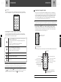
1
00
SECTION
. . .
. . .
IMPORTANT SAFETY INSTRUCTIONS
This symbol found on the apparatus indicates hazards arising from dangerous voltages.
This symbol found on the apparatus indicates the user should read all safety statements
found in the user manual.
WARNING! To reduce the risk of fire or electric shock, do not expose the apparatus to
rain or moisture.
Read these instructions.
Keep these instructions.
Heed all warnings.
Follow all instructions.
Do not use this apparatus near water.
Clean only with dry cloth.
Do not install near any heat sources
such as radiators, heat registers, stoves,
or other apparatus (including amplifiers) that
produce heat.
SETUP AND USE GUIDE
AVIDEA SYSTEM
SETUP AND USE GUIDE
SETUP AND USE GUIDE
Do not defeat the safety purpose of
the polarized or grounding-type plug.
A polarized plug has two blades with one
wider than the other. A grounding type plug
has two blades and a third grounding prong.
The wide blade or the third prong are provided
for your safety. If the provided plug does not
fit into your outlet, consult an electrician for
replacement of the obsolete outlet.
Protect the power cord from being
walked on or pinched – particularly at
plugs, convenience receptacles, and the point
where they exit from the apparatus.
Only use attachments/accessories
specified by the manufacturer.
Unplug this apparatus during lightning
storms or when unused for long periods
of time.
Refer all servicing to qualified service
personnel. Servicing is required when
Maintain a minimum distance of 2 inches
(50mm) around the front, rear, and sides
of the apparatus for sufficient ventilation.The
ventilation should not be impeded by covering
the ventilation openings or placing on or
around the apparatus items such as newspapers,
tablecloths, curtains, etc.
No naked flame sources, such as
lighted candles, should be placed on
the apparatus.
The apparatus should not be exposed
to dripping or splashing. No objects
filled with liquids, such as vases, should be
placed on the apparatus.
The apparatus is suitable for use in
tropical and/or moderate climates.
LASER BEAM: Do not look into the
opening of the disc slot or ventilation
opening of the product to see the source of
the laser beam. It may cause sight damage.
DISC: Do not use a cracked, deformed,
or repaired disc. These discs are easily
broken and may cause serious personal injury
and product malfunction.
NOTE TO CATV SYSTEM INSTALLER:
This reminder is provided to call the
CATV system installer’s attention to Article
820.40 of the NEC that provides guidelines
for proper grounding and, in particular, specifies
that the cable ground shall be connected to
the grounding system of the building, as close
to the point of cable entry as practical.
3
SAFETY INSTRUCTIONS
Do not block any ventilation openings.
Install in accordance with the
manufacturer’s instructions.
the apparatus has been damaged in any way,
such as if the power-supply cord or plug is
damaged, liquid has been spilled or objects
have fallen into the apparatus, the apparatus
has been exposed to rain or moisture, does
not operate normally, or has been dropped.
00
IMPORTANT SAFETY INSTRUCTIONS
TABLE OF CONTENTS
SECTION
00
. . .
. . .
. . .
. . .
SECTION
CAUTION: THIS DIGITAL VIDEO PLAYER EMPLOYS A LASER SYSTEM.
TO ENSURE PROPER USE OF THIS PRODUCT, PLEASE READ THIS USER’S GUIDE CAREFULLY
AND RETAIN FOR FUTURE REFERENCE. SHOULD THE UNIT REQUIRE MAINTENANCE, CONTACT
A BOSTON ACOUSTICS AUTHORIZED SERVICE CENTER.
01
INTRODUCTION
USE OF CONTROLS, ADJUSTMENTS OR THE PERFORMANCE OF PROCEDURES OTHER THAN
THOSE SPECIFIED HEREIN MAY RESULT IN HAZARDOUS RADIATION EXPOSURE.
8
Welcome to Avidea™
9
Supplied Accessories
TO PREVENT DIRECT EXPOSURE TO LASER BEAM, DO NOT TRY TO OPEN THE ENCLOSURE.
VISIBLE LASER RADIATION MAY BE PRESENT WHEN THE ENCLOSURE IS OPENED.
10
Optional Accessories
02
DO NOT STARE INTO BEAM.
8
SECTION
INSTALLATION
11
SECTION
: Location of the Required Label
Complies with FDA radiation performance
standard, 21 CFR subchapter J.
Manufactured by: BOSTON ACOUSTICS INC.
300 Jubilee Drive
Peabody, MA 01960 USA
4
Location of the Required Label
American Users:
This equipment has been tested and found to comply with the limits for a Class B digital device,
pursuant to part 15 of the FCC Rules. These limits are designed to provide reasonable protection
against harmful interference in a residential installation. This equipment generates, uses, and can
radiate radio frequency energy and, if not installed and used in accordance with the instructions,
may cause harmful interference to radio communications. However, there is no guarantee that
interference will not occur in a particular installation. If this equipment does cause harmful
interference to radio or television reception, which can be determined by turning the equipment
off and on, the user is encouraged to try to correct the interference by one or more of the
following measures:
Reorient or relocate the receiving antenna.
Increase the separation between the equipment and receiver.
Connect the equipment into an outlet on a circuit different from that to which
the receiver is connected.
Consult the dealer or an experienced radio/TV technician for help.
CAUTION: Unauthorized changes or modifications to the receiver not expressly approved by
Boston Acoustics could void the user’s authority to operate the equipment.
Canadian Users:
This class B digital apparatus complies with Canadian ICES-003.
Cet appareil numérique de la classe B est conforme á la norme NMB-003 du Canada.
Avidea System Setup
The Avidea Control Center
The Avidea Subwoofer
The Avidea Speakers
12
12
13
13
14
14
Connecting Basic System Components
Inputs and Outputs and the Rear Panel
The Avidea Control Center to the Avidea Subwoofer
The Avidea Speakers to the Avidea Subwoofer
Connecting the RF Receiver/Antenna
Connecting AM and FM Antennas
15
15
16
16
18
20
Connecting Other Devices
About Connections
Connecting Devices
Connecting a Television
Connecting a Cable Box or Satellite Receiver
Connecting Other Audio or Audio/Video Devices
03
OPERATION
SECTION
24
24
25
Introduction to the Avidea Control Center
The Avidea Display
Control Buttons
27
27
Introduction to the Avidea RF Universal Remote
The Avidea Remote Control Layout
28
Turning On the Avidea System
28
29
32
Playing a Disc (DVD or CD)
Controlling a Disc Using the Avidea Remote Control
Controlling a Disc From the Avidea Control Center
5
TABLE OF CONTENTS
SAFETY INSTRUCTIONS
: Regulatory Compliance Statements
11
11
11
11
24
00
TABLE OF CONTENTS
TABLE OF CONTENTS
SECTION
00
. . .
. . .
. . .
. . .
SECTION
33
33
35
36
Operating the AM/FM Tuner
Controlling the AM/FM Tuner Using the Avidea Remote Control
Controlling the AM/FM Tuner From the Avidea Control Center
Selecting Other Devices
36
36
Listening Modes
Introduction to Listening Modes
37
Sleep Mode
06
TROUBLESHOOTING
59
SPECIFICATIONS
63
SPEAKER MOUNTING TEMPLATES
65
SECTION
07
SECTION
08
SECTION
04
ADVANCED OPERATION
38
SECTION
6
Use of the On-Screen Displays (OSD)
The Status Bar
The Setup Menu
44
44
44
45
45
46
46
46
Using the Setup Menu Features
DVD Parental Control
Setting Speaker Levels
Center and Rear Speaker Delay Adjustments
Component Video Assignment
External Source Level Adjustment
Audio Signal Path Assignment
Video Black Level Adjustment
47
MP3 Disc Navigation
47
Customizing Speaker Connections
48
48
50
51
52
Changing the RF/IR Settings
Changing Infrared (IR) Components to Radio Frequency (RF) Control
Changing Avidea Control Center RF Settings
Changing Avidea Remote Control RF Settings
Changing System Remote Control Operation to IR
55
Zone 2 Installation and Operation
05
REFERENCE
SECTION
57
57
57
57
Cleaning the Avidea Control Center and Avidea Speakers
Cleaning the Avidea Remote Control
Replacing the Avidea Remote Control’s Batteries
Glossary of Terms
7
TABLE OF CONTENTS
TABLE OF CONTENTS
38
38
40
57
INTRODUCTION
INTRODUCTION
SECTION
WELCOME TO AVIDEA
01
SECTION
™
. . .
. . .
01
. . .
. . .
SUPPLIED ACCESSORIES
In addition to the main components, you will find the following supplied accessories for your
Avidea system.
Congratulations on your purchase of the Avidea Home Entertainment
System.Your new system incorporates several innovative technologies
designed to deliver a powerful entertainment experience from an
elegant and easy-to-use system.
Please save this Guide for future reference. If you should need an additional
copy, it may be downloaded from the Boston Acoustics website:
www.bostonacoustics.com/avidea.
With your Avidea system, you can enjoy virtually all entertainment sources currently available,
reproduced with the latest generation of multi-channel surround sound formats, and all controlled
by an advanced universal Remote Control. Here is an overview of your Avidea system’s features:
•
8
Elegant, easy-to-use Control Center with slot-loading, progressive scan DVD player. Plays
standard 4 3/4-inch (12cm) size of the following discs: DVD-Video, DVD-Audio, DVD ±RW/±R,
CD, CD-R, CD-R/W, and MP3 CD
Dolby Digital ® EX, DTS® ES, Dolby Pro Logic ® II, and Neo:6
•
High performance AM/FM Tuner with 27 presets in three banks of nine
•
Inputs for up to six additional sources. Includes analog and digital audio inputs, as well as a
convenient forward mounted set of inputs that allow quick connection of video game consoles
and camcorders
•
Universal touchscreen LCD Remote Control uses radio frequencies as well as standard infrared
to operate your system and other components from virtually anywhere in your home. Learns
codes for operating other sources and can be customized with included CD-ROM
•
Powered Subwoofer contains a front-firing DCD ™ driver and amplification for seven
channels
•
Six elegant, compact extruded aluminum speakers feature dual woofer, two-way design and
integrated wall mounts
•
Active equalization and custom crossovers ensure accurate acoustic reproduction
•
Easy-to-use, color-coded speaker connectors for quick and correct system setup
•
Zone 2 audio output that allows independent listening in another part of your home
•
UniView™ video signal management system ensures that all connected video components
operate at maximum performance levels
•
Listening Mode Memory ™ automatically recalls your source listening preferences
•
Powerful On-Screen Display provides total control over your system
•
Optional UMB1 adjustable wall-mount brackets and A7fs floor stands
Speaker Cables : 3 x 16 feet (5m),
3 x 49 feet (15m)
To connect the Avidea Speakers to the Avidea
Subwoofer. A total of six speaker cables are
packed with your system. Each has a colorcoded connector on both ends to match a
speaker. Rear channel speaker cables are
longer to allow for the greater distances
between rear speakers and the Subwoofer.
Avidea Remote Control
Operates the Avidea system and all connected
Devices.
9
Avidea Remote Control Setup and Use Guide
Provides instruction on the use of the Avidea
Remote Control.
Subwoofer Cable : 16 feet (5m)
A special multi-pin cable which is used to
connect the Avidea Subwoofer to the Avidea
Control Center.
Subwoofer AC Cord
Connects to the rear panel of the Avidea
Subwoofer.
RF Receiver/Antenna
Provides signal to the Avidea Control Center
from the Avidea Remote Control. It is connected
to the RF Antenna jack on the rear panel of
the Control Center.
Three AA Batteries
For installation in the Remote Control.
(See separate Avidea Remote Control Setup
and Use Guide for further instructions.)
Serial Cable
Used only when customizing your Avidea
Remote Control from your PC. (See separate
Avidea Remote Control Setup and Use Guide
for further instructions.)
FreedomEdit CD-ROM
Used to customize the Avidea Remote
Control. (See separate Avidea Remote Control
Setup and Use Guide for further instructions.)
I N T R O D U CT I O N
I N T R O D U CT I O N
•
AM and FM Antennas
Provides signal to the Avidea AM/FM Tuner.
01
INTRODUCTION
INSTALLATION
SECTION
S-Video Cable : 6.5 feet (2m)
Used to connect the Avidea Control Center to
the S-Video input/output of a television or
other video component.
02
SECTION
televisions with shallow tops. Depending on
the television, you may need to use the short
or long post to provide support for the rear
of the speaker onto the back of the television.
The short post comes pre-installed, and can be
slightly extended to keep the speaker from
rocking backwards when it is placed on a
flat surface.
. . .
. . .
. . .
. . .
AVIDEA SYSTEM SETUP
: The Avidea Control Center
Composite Video Cable : 5.25 feet (1.6m)
Used to connect the Avidea Control Center to
the Composite Video input/output of a television or other video component.
10
Audio Cable : 5.25 feet (1.6m)
Used to connect the Avidea Control Center to
the stereo input/output of an audio or video
component.
IR Emitter : 6.5 feet (2m)
Provides IR signal to conventional IR
components when using RF to control them.
x Note : Please do not plug the Control Center into an electrical outlet until all other connections are made.
11
Rubber Feet
The self-adhesive feet may be used on the
bottom of the Avidea Speakers to help protect
your furniture. They can also help minimize
the speakers’ movement when the system is
played at high volumes. Place one foot at
each corner at the front bottom edge of the
center channel speaker. Use one foot at each
of the four corners on the bottom of the
other speakers.
: The Avidea Subwoofer
Place the Avidea Subwoofer close enough to the Control Center to allow the supplied subwoofer
cable to reach it. Also, the subwoofer needs to be close to an electrical outlet. Increased bass
performance can be achieved by moving the subwoofer closer to a corner. Ensure that you allow
an adequate distance between the rear of the subwoofer and the wall and other objects for proper
heat dissipation. The subwoofer is not magnetically shielded and should be kept at least 18 inches
(50cm) away from most televisions to avoid interference with the video image.
x Note : Please do not plug the subwoofer into an electrical outlet until all other connections are made.
OPTIONAL ACCESSORIES
The A7fs floor stand and UMB1 wall bracket are available to allow you to place the speakers
around the room in a manner that is convenient and aesthetically pleasing. See your Boston Acoustics
dealer for additional information.
Additional Avidea Remote Controls (A7rc) are available and are particularly useful when establishing
a second Zone outside your main listening area. (See ‘Zone 2 Installation and Operation’ on page 55.)
A 66 foot (20m) CL2-rated Subwoofer cable (A7lc) is available for installations that require long
cable runs between the Avidea Control Center and the Avidea Subwoofer. A CL2 rating is required
when the cable is installed in walls, floors, and ceilings.
: The Avidea Speakers
The Avidea Speakers can be placed on existing shelving or furniture with the application of the
supplied rubber feet to the bottom of the speaker. The speakers can also be wall mounted using
screws and the keyhole mounts on the speaker’s rear panel. Mounting templates are provided at
the back of this guide to assist you in wall mounting the speakers.
x Note : Please consult a qualified installer to assure use of the proper fasteners for your wall surface.
The optional UMB1 wall-mount brackets provide tilt and swivel capability, while the optional A7fs
floor stands place the speaker at the proper listening height in rooms where wall mounting or
shelf placement is not convenient.
I N S TA L L AT I O N
I N T R O D U CT I O N
Center Channel Speaker Posts
Two “threaded posts” are supplied to allow
the center channel speaker to sit properly on
a flat surface or when placed on top of some
Placement of the Avidea Control Center is a matter of convenience. Things to keep in mind
include the distance from the Avidea Subwoofer (it will be connected to the subwoofer with
a supplied 16 foot (5m) cable; an optional A7lc 66 foot (20m) cable is available), and proximity
to an electrical outlet.
02
INSTALLATION
INSTALLATION
SECTION
02
SECTION
The front left and right speakers should be placed on either side of your television. The center
channel speaker should be placed above, on top of, or below your television. Exact placement of
the front three speakers may be determined by what is most visually pleasing, although the best
sound usually is attainable when the left and right speakers are at least six feet apart. The best
location for your rear speakers is dependent on your room and your primary listening position.
If the primary listening position is closer to the middle of the room, then better results may be
obtained by placing the left and right rear speakers on the side walls (see ‘Figure A’ below). If the
primary listening position is closer to the rear of the room, then better results may be obtained
by placing all three rear speakers on the rear wall (see ‘Figure B’ below).
. . .
. . .
. . .
. . .
: The Avidea Control Center to the Avidea Subwoofer
x Note : Please experiment with placement before attaching the speakers to the wall.
Figure B : Rear wall only
Figure A : Side wall and rear wall
Control Center
Subwoofer
Control Center
Subwoofer
Connect one end of the Avidea Subwoofer cable to Connect to Subwoofer/Audio Out on the
Control Center’s rear panel. Plug the other end of the cable into To Control Center located on
the rear of the subwoofer. Make sure that the clamps on the side of the plugs snap into place to
secure the connections.
12
13
: The Avidea Speakers to the Avidea Subwoofer
I N S TA L L AT I O N
I N S TA L L AT I O N
CONNECTING BASIC SYSTEM COMPONENTS
: Inputs and Outputs and the Rear Panel
All speaker connections are made to the rear panel of the subwoofer using the supplied cables.
Cables for the front speakers are 16 feet (5m) while the rear speaker cables are 49 feet (15m),
since rear speakers are typically farther away from the subwoofer.
Connect the Avidea Speakers by matching the color-coded speaker connector to the same colorcoded receptacle on the rear of the subwoofer and to each individual speaker.
The color-coding is as follows:
A total of six different Devices can be connected to the Avidea Control Center using the inputs
on the side and rear panel. The Front inputs (located on the right/front side) are convenient
when making connections to game consoles or camcorders.
Please do not plug the subwoofer or Control Center into an electrical outlet until all
other connections are made.
•
Front Right [ FR ] : Red
•
Rear Right [ RR ] : Grey
•
Front Center [ FC ] : Green
•
Rear Center [ RC ] : Brown
•
Front Left [ FL ] : White
•
Rear Left [ RL ] : Blue
x Note : The speaker cables are supplied with a unique connector at each end. To shorten the supplied speaker cables
or replace them with longer wires, see ‘Customizing Speaker Connections’ on page 47.
02
INSTALLATION
INSTALLATION
SECTION
The speakers include keyholes on the rear panel for convenient wall mounting with screws. Once
mounted, wire may pass out either end of the speaker. There is also a small notch in the middle of
the bottom edge of the center channel speaker to allow its speaker wire to exit at that point
rather than at the end.
x Notes : Templates to assist you in wall mounting the speakers can be found on the last page of this Guide.
Connecting additional speakers to your Avidea system requires the use of the Zone 2 audio outputs and an
additional amplifier. (See ‘Zone 2 Installation and Operation’ on page 55.)
: Connecting the RF Receiver/Antenna
02
SECTION
. . .
. . .
. . .
. . .
Connections for both antennas are located on the far left section of the Avidea Control Center’s
rear panel. Attach the two bare wire ends of the AM antenna to the two spring-loaded AM connectors.
Press the lever to open the hole, and release the lever once the wire is inserted. Position the AM
antenna as far from the Avidea Control Center as the antenna wires allow (at least 18 inches). You
should experiment with the antenna’s orientation in order to optimize your AM reception.
Different AM stations may require re-orienting the AM antenna.
Plug the FM antenna into FM 75 Ω and uncoil the antenna.You should experiment with the antenna’s
orientation in order to optimize your FM reception.
x Note : It is possible to improve radio reception with the use of accessory antennas. Please consult your Boston
Acoustics dealer.
CONNECTING OTHER DEVICES
: About Connections
When connecting video Devices (cable boxes, satellite receivers, VCRs, etc.), separate cables are
required for the picture (video) and the sound (audio). Avidea offers a choice of connections for
each component. Select the highest performance connections available from your Devices as
explained below.
14
15
Audio Inputs and Outputs can be either digital or analog, with digital being the higher quality.
In most cases, match color-coded outputs on your Device to inputs on your Avidea system.
The supplied RF Receiver/Antenna must be plugged into the Avidea Control Center to
allow the Avidea Remote Control to operate the Avidea Control Center.
The Avidea Remote Control communicates with your Avidea system via Radio Frequencies (RF).
This feature allows you to control the system even when it is in a closed cabinet or from another
room. Plug the Receiver/Antenna into RF Antenna In located on the right side of the rear panel
of the Control Center. The RF Receiver/Antenna should be placed as far away as possible from the
Control Center and other metal objects to maximize the operating range and the effectiveness of
the Remote Control. Maximum Remote Control range is approximately 66 feet (20m), although
local interference and building construction materials can reduce this distance.The RF Receiver/Antenna
may be laid on its back or side on any flat surface. To attach the RF Receiver/Antenna to a vertical
surface, you may mount it using its integrated keyhole. As an option, any of a variety of self-adhesive
wall mounting products may be used.
: Connecting AM and FM Antennas
three separate cables color-coded Green (Y), Blue (Pb), and Red (Pr). Typically, only high definition and digital sources offer Component video connections.
• Excellent Picture : S-Video connectors have several small pins located within an outer ring.
They are “keyed” so that they can only be inserted when all the pins line up correctly.
• Standard Picture : Standard Composite video should only be used when neither of the
above connections is available. It is usually color-coded Yellow.
I N S TA L L AT I O N
I N S TA L L AT I O N
Video Connections
• Best Picture : Component Video connections provide the highest resolution available, using
02
INSTALLATION
INSTALLATION
SECTION
02
SECTION
Audio Connections
• Digital : A Digital Coaxial cable, usually color-coded Orange, or a Fiber Optic Toslink cable
provides the highest quality sound.
. . .
. . .
. . .
. . .
Your Avidea system is equipped with a progressive scan DVD player. To avoid potential incompatibility
problems, Avidea is set to the interlace or INT mode. If you are connecting to a digital television
you must move this switch to the PROG setting to gain maximum performance. When the Avidea
Control Center is switched to progressive scan mode, there is no output from the Composite or
S Monitor Out (To TV).
x Note : The Avidea Remote Control must be programmed to operate your television. (See ‘Entering Codes for Other
Devices’ on page 21 of the Avidea Remote Control Setup and Use Guide.)
x Note : Use only one Digital connection per Device. Use coaxial if both coaxial and optical are available.
x Important Note : There are two sets of Component Video connectors on the rear panel of the Avidea Control Center.
Make sure that you connect your TV’s Component Video Inputs to Monitor Out (To TV) Component and NOT to
the Component Video In. Component Video Cables are color-coded: Green (Y), Red (Pr), and Blue (Pb). Make sure
to match the connectors to the same colored jacks.
• Analog : Standard audio connectors provide high quality analog audio. Although the left
connector is usually color-coded White, it sometimes may be Black or Grey.
16
Connecting a Standard TV with S-Video
: Connecting Devices
17
x Note : Each Device connection diagram may show more than one connection method, as it is not known what
type of inputs and outputs are available on your Devices. Your Devices may have better connection capability, for
example S-Video is better than composite, or digital audio is better than analog. Always attempt to use the highest
quality connection available. (See ‘About Connections’ on page 15 for more information.)
Connect the S-Video cable from Monitor Out (To TV) S on the rear panel of the Control Center
to an S-Video Input on your TV.
x Note : The Avidea Remote Control must be programmed to operate your television. (See ‘Entering Codes for Other
Devices’ on page 21 of the Avidea Remote Control Setup and Use Guide.)
: Connecting a Television
Connecting a Digital TV
Connecting a Standard TV with Composite Video
INT/PROG switch
Switch to PROG
High Definition and Digital TVs provide Component Video Inputs. To take full advantage of this
type of equipment, Component Video Connections should be used. Connect a Component Video
cable (not supplied) from Monitor Out (To TV) Component on the rear panel of the Control
Center to a Component Video Input on your TV.
Connect the Composite Video cable from Monitor Out (To TV) Composite on the rear panel of
the Control Center to a Composite Video Input on your TV.
x Note : The Avidea Remote Control must be programmed to operate your television. (See ‘Entering Codes for Other
Devices’ on page 21 of the Avidea Remote Control Setup and Use Guide.)
I N S TA L L AT I O N
I N S TA L L AT I O N
To connect Devices, match outputs to inputs. In most cases, match similar, color-coded jacks with
the appropriate cable. Here is a list of the most commonly connected Devices, as well as the
different methods of connecting them.
02
INSTALLATION
INSTALLATION
02
SECTION
: Connecting a Cable Box or Satellite Receiver
SECTION
. . .
. . .
. . .
. . .
Connecting a Digital Cable Box or Satellite Receiver
Connecting a High Definition (HD) Cable Box, HD Satellite Receiver, or
HD Terrestrial Receiver
Connect a Digital Audio cable (not supplied) from the Digital Audio Out on the Cable Box or
Satellite Receiver to the Cable/Sat Digital Audio on the rear panel of the Control Center.
Connect the S-Video Output from the Digital Cable Box or Satellite Receiver to the Cable/Sat S
Input on the rear panel of the Control Center. If a Digital Audio Output and/or S-Video Output
are not available on your Digital Cable Box, you may use Analog Audio and/or Composite Video.
18
Connect a Component Video cable (not supplied) from the Cable Box or Receiver Video out to
Component Video In on the rear panel of the Control Center. Connect a Digital Audio cable
(not supplied) from the Cable Box or Receiver Digital Audio Output to Cable/Sat Digital Audio.
x Note : The Avidea Remote Control must be programmed to operate your Cable Box or Satellite Receiver.
(See ‘Entering Codes for Other Devices’ on page 21 of the Avidea Remote Control Setup and Use Guide.)
Connecting Audio from a TV Using a Standard Cable Box
x Important Note : You must assign the Component Video Inputs to the Cable/Sat Device. (See ‘Component Video
Assignment’ on page 45.)
x Notes : The Avidea Remote Control must be programmed to operate your Cable Box or Satellite Receiver.
(See ‘Entering Codes for Other Devices’ on page 21 of the Avidea Remote Control Setup and Use Guide.)
It is possible to connect both a Digital Cable Box and a Satellite Receiver to the Avidea Control Center. Connect either
Device to the Cable/Sat input, and then use another, unused audio/video input (Changer, VCR, or TV) for the other
Device. You can relabel that other Device on the Avidea Remote Control. Use FreedomEdit and your PC to change the
Device associated with the other input. (See the FreedomEdit CD-ROM that came with your Avidea Remote Control.)
Connect the cable wire from your cable company to the Cable Input on the cable box. Connect
the To TV Output from the cable box to the ANT Input on your TV. Connect the Audio Output from
your TV to Cable/Sat Audio on the rear panel of the Control Center. You may wish to permanently
shut off the TV’s internal speakers and set the TV’s audio output to “fixed” if that option is available.
Please consult your TV owner’s manual.
x Notes : The Avidea Remote Control must be programmed to operate your Cable Box. (See ‘Entering Codes for Other
Devices’ on page 21 of the Avidea Remote Control Setup and Use Guide.) Select Cable/Sat on your Avidea Remote
Control to operate your cable box.
This configuration will not allow use of the Avidea Status Bar or Setup Menu while watching TV.
I N S TA L L AT I O N
I N S TA L L AT I O N
HD Cable Boxes and Receivers provide Component Video Outputs. To take full advantage of this
type of equipment, Component Video Connections should be used.
19
20
02
INSTALLATION
INSTALLATION
SECTION
02
SECTION
Connecting Audio from a TV Using an Antenna or Cable Without a Cable Box
Connecting a Cassette Deck
If you are using the Tuner in your TV to watch cable or regular off-air programming, you will need
to supply the audio signal to the Avidea system. Connect your TV’s Audio Out to the TV (From
TV) Audio on the rear panel of the Control Center. You may wish to permanently shut off the TV’s
internal speakers and set the TV’s audio output to “fixed” if that option is available. Please consult
your TV owner’s manual.
Connect the Audio Outputs (Play) on your Cassette Deck to the Aux Audio In on the rear panel
of the Control Center. Connect the Audio Inputs (Rec) on your Cassette Deck to the Aux Audio
Out on the rear panel of the Control Center.
x Notes : The Avidea Remote Control must be programmed to operate your TV. (See ‘Entering Codes for Other Devices’
on page 21 of the Avidea Remote Control Setup and Use Guide.)
This configuration will not allow use of the Avidea Status Bar or Setup Menu while watching TV.
Connecting a MiniDisc or CD Recorder
: Connecting Other Audio or Audio/Video Devices
Connecting a VCR or PVR (Personal Video Recorder)
TV (From TV)
Video
Composite
S
Component RF
Monitor Out (To TV)
Composite
Video
S
Antenna
Video In
Component
Y
In
Y
IR 1
Pb
Pb
Pr
Pr
Zone 2 Trigger
Audio
770
DVD Control Center
Rating : AC 120V 80Hz
50W
Boston Acoustics, Inc.
Peabldy, MA USA
Designed in USA / Made in China
IR 2
WAR NING
RISK OF ELECTRIC SHOCK
DO NOT OPEN
L
L
R
R
Ch
Analog
Digital
Audio Out
ID
Int.
Out
AV IS
RISQUE DE CHOC ELECTRIQUE
NE PAS OUVRIR
+12V
C
UL
®
US
LISTED
E206909
7H57
AUDIO/VIDEO
EQUIPMENT
Connect To Subwoofer
Prog.
Audio Out
Remote
Connect the Audio and Video Outputs on your VCR or PVR to the VCR/PVR Audio In and Video
In on the rear panel of the Control Center. Connect the Audio and Video Inputs on your VCR or
PVR to the VCR/PVR Audio Out and Video Out on the rear panel of the Control Center. Owners
of certain PVRs used in conjunction with a satellite receiver or digital cable box may want to
connect the two Devices directly to each other for recording. Please consult your PVR owner’s
manual for details.
You must set the Avidea Control Center to Stereo or 5 speaker mode when recording to a VCR or
PVR from other Devices connected to the Avidea system. (See ‘Listening Modes’ on page 36.) To
record from any Device to a VCR or PVR, that Device must be connected by an analog audio cable.
MiniDisc (MD) and CD Recorders offer digital connections. Use the appropriate connectors
(not supplied) to connect the Audio Outputs (Play) from your MiniDisc or CD recorder to the
Aux Audio In on the rear panel of the Control Center. Connect the Audio Inputs (Rec) from
your MiniDisc or CD recorder to the Aux Audio Out on the rear panel of the Control Center.
You must set the Avidea Control Center to Stereo or 5 speaker mode when recording to an MD/CD
Recorder from other Devices connected to the Avidea system. (See ‘Listening Modes’ on page 36.)
To record from any Device to an MD/CD Recorder, that Device must be connected by a digital
audio cable (not supplied). If a digital output is not available for a Device from which you wish to
record, then use an analog audio cable and connect your MD/CD recorder with an analog cable in
addition to a digital cable. Consult your MD/CD Recorder owner’s manual to record from an analog
signal.
21
I N S TA L L AT I O N
I N S TA L L AT I O N
You must set the Avidea Control Center to Stereo or 5 speaker mode when recording to a Cassette
Deck from other Devices connected to the Avidea system. (See ‘Listening Modes’ on page 36.) To
record from any Device to a Cassette Deck, that Device must be connected by an analog audio cable.
. . .
. . .
. . .
. . .
02
INSTALLATION
INSTALLATION
SECTION
Connecting a CD Changer
Connect the Audio Outputs from your CD Changer to the Changer Audio Inputs on the rear
panel of the Control Center. Some CD Changers have digital as well as analog outputs. You may
choose to use either one.
22
Connecting a DVD Changer
02
SECTION
Connecting a Forward-Mount Game or Camcorder
The headphone jack is located on the right side of the Avidea Control Center. Inserting
a headphone jack will mute all the Avidea system’s speakers.
x Note : The headphone jack is 1/8 inch (3.5mm), standard for most headphones. An optional adapter
(not included) will enable you to connect other size plugs, and is available at your Boston Acoustics dealer.
x Note : The library of Device codes associated with the Changer are for CD players and CD Recorders. Any given
brand of DVD player or recorder may use the same codes. If that is not the case for your Device, then you may use
Learning Mode to teach all the appropriate commands from the original Remote Control to the Avidea Remote
Control. You may also choose to use FreedomEdit and your PC to change the Device associated with the Changer
input. (See the FreedomEdit CD-ROM that came with your Avidea Remote Control.)
23
I N S TA L L AT I O N
I N S TA L L AT I O N
The set of inputs mounted on the right side of the Control Center allow you to connect and
disconnect components without having to move the Control Center to access the rear panel.
Devices that may be connected on a temporary basis include camcorders and video games.
These devices usually include special cables that supply audio and video outputs. You may want
to refer to your camcorder or video game manual for more information on connecting them to
other components.
Connecting Headphones
Connect the Digital Audio Output from your DVD Changer to the Changer Audio Input on the
rear panel of the Control Center. Connect the Video Out on your DVD Changer to the Changer
Video Input. If your DVD Changer is progressive scan, connect its Component Video Outputs to
Component Video In, unless it is already being used by your HD Cable Box, Satellite Receiver,
or Terrestrial Receiver. If that is the case, use S-Video instead.
. . .
. . .
. . .
. . .
OPERATION
OPERATION
SECTION
03
SECTION
. . .
. . .
03
. . .
. . .
INTRODUCTION TO THE AVIDEA CONTROL CENTER
The Avidea Control Center is the heart of your system. It contains a DVD/CD player, AM/FM
Tuner, video/audio inputs and outputs plus all the circuitry needed to control your entire home
entertainment system. The Control Center can be operated directly by use of the controls on
the unit or with the supplied Avidea Remote Control.
6 Lights : 6 Speakers Playing
On the front of the Control Center is the disc player slot and the disc eject button. The system
display area is surrounded by six small, blue speaker indicator lights that show how many
speakers are playing.
: The Avidea Display
Device Playing
Chapter, Track,
Station, or Folder
Playing
Play Mode
Time Into Selection
5 Lights : 5 Speakers Playing
Disc Indicator
24
25
Sleep Timer
ON + Time
Random Function
ON/OFF
O P E R AT I O N
O P E R AT I O N
Zone 2 ON
and Device
Repeat Function
ON/OFF
Night Mode ON
2 Lights : 2 Speakers Playing
•
Typically, the display shows the current Device, the play mode, current track/chapter/preset,
and elapsed time or Tuner setting. The specific information displayed differs for each Device.
The display also indicates, if Zone 2, Night, or Sleep modes are active. (See ‘Zone 2 Installation
and Operation’ on page 55 and ‘Sleep Mode’ on page 37 for more information on these operations.)
•
If you are changing the Device, volume, or other state of the Device, via either the Control
Center controls or Remote Control, that information is also briefly displayed in a larger size.
x Note : The information on the Control Center’s display is also communicated via the On-Screen Display Status
Bar. (See ‘Use of the On-Screen Displays (OSD)’ on page 38.)
Display Brightness
When a button is pressed on the Control Center or a command is sent to the Control Center
from the Remote Control, the display brightens to maximum brightness. The display remains
bright for five seconds after the last button is released.
The Avidea Speaker Indicator Lights
Surrounding the display area are six small blue lights, representing the position of each speaker
in the room. The lights that are on correspond to those speakers that are playing.
x Note : The Avidea Subwoofer is always on when the Avidea system is on.
: Control Buttons
The buttons on the Avidea Control Center provide a simple level of control over the Avidea system.
System level controls (Power, Source, Volume +, Volume -) are always active and always have the
same function.
and
change function depending on the Device, and have no function when
the Device is external to the Control Center. The eject button is next to the disc slot for removing
a disc from the system.
Power
Source
Volume
03
OPERATION
OPERATION
SECTION
03
SECTION
. . .
. . .
. . .
. . .
INTRODUCTION TO THE AVIDEA RF UNIVERSAL REMOTE
CONTROL BUTTON
WHAT IT DOES
x Note : The full setup and use of the Avidea Remote Control is covered in the separately supplied Guide.
Turns the Avidea system on or off.
Power
Source
Selects the next source (Device) and puts the display into “source mode.”
This button only responds to a single press, and does not repeat if held.
When using Disc, press to go to the beginning of the current chapter/track,
if current chapter/track playing time is more than five seconds.
(Disc)
Goes to the previous chapter/track, if current chapter/track playing
time is less than five seconds.
Press again to go to the beginning of the previous chapter/track.
Press-and-hold to play in reverse at 4x normal speed.
The Avidea Remote Control communicates to the Avidea Control Center using Radio Frequencies
(RF) and not conventional Infrared (IR). Unlike IR, RF signals penetrate walls, ceilings, and cabinetry.
This means that you can control your system without pointing the Remote Control at the system,
if it is hidden away in a closed cabinet, or even from another room. This functionality provides a
level of convenience and flexibility not available from conventional remotes. The Remote Control
has a maximum range of approximately 66 feet (20m).
The Avidea Remote Control is designed to control everything connected to your Avidea system.
This is accomplished by utilizing the built-in library of codes for other manufacturers’ remotes, or
through the Avidea Remote Control’s learning capability. Additionally, the Avidea Remote Control
can be customized using the supplied FreedomEdit software.
The Avidea Remote Control requires three AA batteries (3 x 1.5 volts) to function. You can use
either the supplied batteries or purchase rechargeable batteries.
: The Avidea Remote Control Layout
26
(Tuner)
When using Tuner, selects the next Tuner preset down from the last preset
chosen. Starts from preset A1 if preset tuning has not been previously
used.This will occur even if there are no stations stored in any preset.
The Avidea Remote Control has “hard” buttons and touchscreen “soft” buttons. Touchscreen buttons
are simulated buttons you can press on the LCD touchscreen. Hard buttons are all the other buttons
on the Avidea Remote Control.
O P E R AT I O N
O P E R AT I O N
When using Disc, press to go to the beginning of the next chapter/track.
TV Power
Press again to go to the beginning of the next chapter/track.
(Disc)
Press-and-hold to play forward at 4x normal speed.
Avidea System Power
LCD Touchscreen
Soft Buttons
(Tuner)
When using Tuner, this works like the
forward direction.
control, but in the
OSD Button (Opens Avidea On-Screen Display)
Close Button (Closes Avidea On-Screen Display)
(CD/DVD)
Stops a disc. For a DVD, a single press will stop the Disc, but DVD will
resume play at the same point. Press stop twice to return to the main
DVD menu.
Backlight Button
Device Button (Displays Device selection page)
Page Up Button
Channel Up/Down
(CD/DVD)
Volume
If a disc is playing, this will put the disc into pause. If the disc is already
paused, pressing the button will resume playing the disc.
Turns the volume down one level with each press. Press-and-hold to
turn the volume down continually and rapidly.
TV Source (TV input selector)
Page Down Button
Mode Button
(Press-and-hold for three seconds to switch
Remote Control to another mode)
Avidea System Volume Up/Down
Navigation Buttons
Volume
Turns the volume up one level with each press. Press-and-hold to turn
the volume up continually and rapidly.
x Note : The first time you turn on your Avidea system it will play at a volume setting of "70" (volume range is 0 to 100).
With any future use, Avidea will turn on at "70" if last used at that volume or higher. This is to prevent accidentally
turning on the system at an excessive volume. If last used at a volume less than "70", Avidea will turn on at that volume.
Avidea System Mute
Serial Port for connecting to a PC
27
Learning Eye
03
OPERATION
OPERATION
SECTION
SECTION
Using the Touchscreen Buttons
You operate the touchscreen buttons in the same way you operate hard buttons on a conventional
remote control. When you keep the touchscreen button pressed, the Avidea Remote Control keeps
sending the command for up to 30 seconds. Once you have selected a Device, the name of the
active Device is indicated at the top of the touchscreen.
Press Play on the Avidea Remote Control to start a CD playing. A DVD will play until it reaches
its menu. Use the Remote Control Navigation buttons to move within the DVD menu and make
selections. When inserting any type of disc, the system must be on and Disc must be the
selected Device.
x Notes : The Control Center will not accept a disc if there is a disc already in the unit.
Using the Hard Buttons
Hard buttons can be operated at any time, even without turning on the LCD touchscreen. In addition
to TV control, the Channel -/+ buttons have functionality for other devices. In Disc operation,
the channel buttons are used to change chapters for DVDs or tracks for CDs. In Tuner operation, the
channel buttons are used to change presets.
Using the Page Up and Page Down Buttons
Devices have more than one page of LCD touchscreen buttons. You can scroll through these pages
using the Page Up and Page Down buttons on the left side of the Remote Control. The page number
on the left of the touchscreen indicates the active LCD page number and the total number of LCD
pages. For example, 1/6 means you are on page 1 of a total of 6 pages.
Your Avidea system plays Region 1 DVDs. To ensure compatibility, only purchase discs that show the Region 1
designation on the disc label or packaging.
: Controlling a Disc Using the Avidea Remote Control
There are six LCD pages for controlling the Avidea Disc Player. Selecting Disc from the Devices
page will turn on the Avidea system if it is off, switch the source to Disc, and switch the Remote
Control to Disc page one.
Disc Control
The first LCD page provides touchscreen button control of basic disc functions.
x Note : The full setup and use of the Avidea Remote Control is covered in the separately supplied Guide.
28
03
. . .
. . .
. . .
. . .
TURNING ON THE AVIDEA SYSTEM
29
The Avidea system may be turned on by:
Goes to individual DVD title
menu (if available)
Goes to the DVD’s main
menu of selections
or
Pressing Power on the Remote Control.
Increases play speed in
forward direction
(See table below)
Increases play speed in
reverse direction
(See table below)
or
Selecting a Device on the Remote Control which will automatically
display LCD page one for that Device.
PLAYING A DISC (DVD OR CD )
Stops disc
Navigation
Button: Up
Navigation
Button: Left
Navigation Button: OK
(Acts as “Enter” for some Devices)
Each press of Fast Forward or Fast Reverse will increase speed of forward/reverse play as follows:
Fourth press
f 16x speed
Second press f 4x speed
Fifth press
f 30x speed
f 8x speed
Sixth press
f 60x speed
First press
Device
Button
Third press
f 2x speed
Navigation
Button: Right
x Note : The Navigation buttons on the Remote Control are used to move within menus. Additionally, the Channel -/+
hard buttons function as skip forward/backward touchscreen buttons.
Navigation Button: Down
x Warning: The Avidea Control Center is designed to play standard size 4 3/4-inch (12cm) discs only. Do not
insert 3-inch (8cm) discs. Once inserted, these discs cannot be removed.
Plays disc
Pauses disc
Your Avidea system can play 4 3/4-inch (12cm) size Turns Avidea
DVD-Video discs (DVD, DVD ±RW/±R), DVD-Audio system ON and
selects Disc
discs, audio CDs (CD, CD-R, CD-R/W), and MP3
as Device
CDs. The control center display will indicate what
type of disc you are listening to, the chapter/
track number, the chapter/track time, and if random or repeat modes are engaged.
The Avidea Control Center must be on to accept
a disc. Insert a disc label side up. Select Disc using
the Control Center Source button or press disc
on the Avidea Remote Control Device page. Press
the Device hard button if the Device page is not
displayed.
Goes to the beginning of the
next chapter/track
Goes to the beginning of the
current or previous
chapter/track
O P E R AT I O N
O P E R AT I O N
Exits selected DVD menu
Goes back one step within a
currently selected DVD menu
Pressing Power on the Control Center.
03
OPERATION
OPERATION
SECTION
SECTION
Disc Listen
Disc Special
The second LCD page on the Remote Control for Disc function provides touchscreen buttons to
select the Listening Mode as either stereo, surround music, surround movie, and provides five or
six speaker control. (See ‘Listening Modes’ on page 36 for more details.)
Turns off all Avidea Control Center
lights except Power, and allows
only basic operation. Press again
to restore lights
Uses only the front left and
front right speakers
Reduces difference between
loudest and softest passages
(DVDs only)
03
. . .
. . .
. . .
. . .
Displays the Avidea Status Bar
The fourth LCD page on the Remote Control for Disc function provides touchscreen buttons for
additional DVD control options.
Increases reverse play speed
(See table below)
Increases forward play speed
(See table below)
This feature is not supported
at this time.
Pauses disc and plays one frame
per press
Decreases reverse
slow-motion play
(See table below)
Decreases forward slow-motion
play (See table below)
Uses 5 or 6 speakers for movie
viewing
Reverse play
Uses 5 or 6 speakers for music
listening
Plays disc
Turns the rear center speaker
on and off
Changes viewed camera angle
(If available)
Pauses disc
Each press of Fast Forward and Fast Reverse will increase speed of forward/reverse play as follows:
30
Adjusts the amount of bass coming
from the Avidea Subwoofer
Disc Track
The third LCD page on the Remote Control for Disc function provides touchscreen buttons to allow
more direct access to disc programming.
Press and then use numbers to go to a specific
time on DVD in hours, minutes, and seconds
(00:00:00). Press OK Navigation button when
complete time is entered
f 2x speed
Fourth press
f 16x speed
Second press f 4x speed
Fifth press
f 30x speed
f 8x speed
Sixth press
f 60x speed
First press
Third press
Slow Forward and Slow Backward provide control at reduced speeds in forward and reverse
direction. Each press of a Slow button provides a different speed in the selected direction.
First press
f 1/2 speed
Second press
f 1/4 speed
Third press f 1/8 speed
Disc Repeat
The fifth LCD page on the Remote Control for Disc function provides touchscreen buttons to allow
additional disc programming.
For scrolling backwards
within MP3 playlists
For scrolling ahead within MP3
playlists
Numbers used to access chapter, time, or title (DVD) or track
(CD)
Uses numbers to select specific
chapter or tile on DVD or track
on CD. Press enter to go to
track, title, or track.
x Note : To access a specific title on a DVD that contains multiple titles, first press “0”, followed by the title number, then press
“enter.”
Changes the order of
CD track play
Press to repeat CD track,
press again to repeat the
entire CD, press again
to turn CD repeat off
Press to repeat DVD chapter,
press again to turn DVD repeat off
Press set to start DVD play loop,
press set again to end DVD play
loop. Press clear to stop DVD play
loop and return to normal play
O P E R AT I O N
O P E R AT I O N
x Note : When playing a DVD, Avidea will automatically select Dolby Digital or DTS, depending on what is
available on the DVD and what has been selected by the user. For this reason, Surround Music and Surround
Movie (Dolby Pro Logic II and Neo:6) will not be available for use with a DVD.
31
03
OPERATION
OPERATION
SECTION
03
SECTION
Disc Macros
The sixth LCD page provides an array of blank touchscreen buttons that can be programmed as
macros. (See ‘Recording Macros’ on page 28 in your Avidea Remote Control Setup and Use Guide.)
. . .
. . .
. . .
. . .
OPERATING THE AM /FM TUNER
Your Avidea system contains a high performance AM/FM Tuner. The Tuner can be manually tuned
to a station or you can use seek mode to go up or down through radio frequencies and automatically
stop at the next available station. You can store up to 27 preset stations, organized into three banks
(A, B, and C) with nine presets in each bank. This allows you to organize preset stations by user
or type of station programming. A preset consists of the band (FM or AM), the station frequency
(e.g., 89.7), and whether an FM station should be tuned in Mono mode.
x Note : It is possible that some FM stations you receive can sound noisy or distorted. Try reorienting the FM antenna or
pressing the Mono touchscreen button located on Tuner LCD pages one and four. If you tune an FM station in Mono mode,
you may store it as a preset that way. Any time you recall that preset that station will be tuned in Mono automatically.
: Controlling the AM/FM Tuner Using the Avidea Remote Control
The Remote Control provides five LCD pages for control and programming of all Tuner functions.
Selecting Tuner from the Devices page will turn the Avidea system on if it is off, switch the Device
to Tuner, and switch the Remote Control to Tuner page one.
: Controlling a Disc From the Avidea Control Center
32
You can control the Disc Player using the buttons on the Control Center or with your Avidea
Remote Control. The buttons on the Control Center provide basic operation of the Disc Player.
Here are the functions of the Control Center buttons.
Turns Avidea system on and
selects Tuner as Device
33
O P E R AT I O N
O P E R AT I O N
Press to go to the beginning of the current chapter/track, if current chapter/track
playing time is more than five seconds.
Goes to the previous chapter/track, if current chapter/track playing time is less
than five seconds.
Press again to go to the beginning of the previous chapter/track.
Press-and-hold to play in reverse at 4x normal speed.
Tuner Cntrl (Control)
Press to go to the beginning of the next chapter/track.
Press again to go to the beginning of next chapter/track.
The first LCD page provides touchscreen button control of AM, FM, and FM Mono Mode band selection.
Press-and-hold to play forward at 4x normal speed.
Selects FM band
Stops a disc.
Plays a stopped disc. Pauses a playing disc.
Ejects the disc.
x Note : When you press “Stop” during DVD play, the system will retain the position at which the disc was stopped;
if you press “Play”, the disc will resume from its stopped position. If you press “Stop” a second time before pressing
another transport key, the stop position will be reset and the disc will start from the beginning on the next press of
“Play.” Switching Devices, changing discs, or turning the Avidea system off defeats this feature.
If the disc has been stopped and the
button is pressed, the first chapter/track is selected. If you
press
five times, the fifth chapter/track is selected. When a chapter/track is selected, the “track”
display shows this chapter/track, and when you press
, this chapter/track will play.
Selects AM band
Switches FM band to Mono
Goes down to the next
available frequency and stops
Goes up to the next available
frequency and stops
Goes down to the next
available station and stops
Goes up to the next available
station and stops
Selects A, B, or C preset
bank. Each bank holds
up to 9 presets
Changes presets down or up within a bank.
Goes to the previous or next bank after first
or last preset within a bank
x Note : The channel -/+ hard buttons function like the preset -/+ touchscreen buttons.
03
OPERATION
OPERATION
SECTION
03
SECTION
Tuner Listen
Tuner Direct
The second LCD page provides touchscreen buttons to select the Listening Mode as either stereo
or surround music, and provides 5 or 6 speaker control. There are also controls for the Status Bar,
the Control Center Display, as well as the subwoofer volume. (See ‘Listening Modes’ on page 36
for more details.)
Turns off all Avidea Control Center
lights except Power, and allows
only basic operation. Press again
to restore lights
Uses only the front left and front
right speakers
. . .
. . .
. . .
. . .
The fourth LCD page allows you to tune directly to an AM or FM station by frequency. First choose
the band you wish to access: AM, FM, or FM Mono. Enter all the digits for that station. For example:
102.5 would be entered as “1”,“0”,“2”,“5”. Then press enter.
Selects FM band
Displays the Avidea Status Bar
Selects AM band
Uses 5 or 6 speakers for
music listening
Switches FM band to Mono
Numbers used to select station
frequency
Turns the rear center speaker
on and off
Tunes selected frequency
Adjusts the amount of bass coming
from the Avidea Subwoofer
34
Tuner Macros
35
Tuner Preset
The fifth LCD page provides an array of blank touchscreen buttons that can be programmed as
macros. (See ‘Recording Macros’ on page 28 in your Avidea Remote Control Setup and Use Guide.)
Begins/ends the store
preset process
Numbers used to select/store
a preset number
Selects/stores A, B, or C
preset bank. Each bank
holds up to 9 presets
: Controlling the AM/FM Tuner From the Avidea Control Center
(1) Press “store preset” to begin storing a preset. Go to LCD page one or four to tune to the
desired frequency. Return to this LCD page.
(2) Press A, B, or C to select a preset bank.
(3) Select 1–9 to select a preset number.
You can control the Tuner using the buttons on the Control Center or with your Avidea Remote
Control. The Control Center buttons provide basic operation of the Tuner. Here are the functions
of the Control Center buttons.
Rev (Tuner)
Selects the next Tuner preset down from the last preset chosen. Goes to
the previous bank after first preset within a bank. Starts from preset A1
if preset tuning has not been previously used.This will occur even if
there are no stations stored in any preset.
Fwd (Tuner)
This works like the Tuner Rev control, but in the forward direction.
(4) Press “store preset” to finish storing a preset.
(5) The Control Center displays “Preset Stored.”
x Note : If more than 5 seconds passes between any step in the process, the action is cancelled.
To recall a stored preset using this LCD page, press the bank and preset number.
O P E R AT I O N
O P E R AT I O N
The third LCD page provides touchscreen buttons for storing and recalling Tuner Presets.
03
OPERATION
OPERATION
SECTION
: Selecting Other Devices
Other Devices (sources) that are connected to the Avidea Control Center are selected using
the Source button on the Control Center or the Device page on the Remote Control. Selecting
a Device from the Device page will turn the Avidea system on if it is off, switch the source to
selected Device, and switch the Remote Control to page one for that Device. Changing sources
will be reflected on the Control Center Display as well as in the Status Bar.
LISTENING MODES
: Introduction to Listening Modes
The Avidea system automatically decodes all Devices for the best possible sound quality while
using all the system’s speakers for a terrific surround sound experience. If you prefer, Listening
Modes allow you to use fewer speakers and adjust the amount of bass.
03
SECTION
. . .
. . .
. . .
. . .
Sub -/+ (Adjusting the Amount of Bass Output)
These touchscreen buttons adjust the amount of bass coming from the Avidea Subwoofer. There
may be situations when more or less bass is desired. More bass may be desirable when watching
certain movie soundtracks, or when the system is played at a low volume level. Less bass may be
desirable in certain listening rooms that naturally emphasize bass frequencies.
The subwoofer volume control (– subw +) is found on the Listen Mode page, the second page of
each Device. The range of this control is -12 to +12, and a visual indication of any level change will
appear on the Control Center display as well as on the television by way of the Status Bar Display.
(See the ‘Use of the On-Screen Displays (OSD)’ on page 38.)
Display
This touchscreen button shuts off the speaker status lights, the Control Center display, and all
control button lights except “Power.” When the Avidea Control Center display is in the “off” mode,
only the following remote control buttons continue to operate:
• Hard Buttons: Volume +/-, Mute, Channel (Chapter/Track) +/-
x Note : The Avidea Subwoofer always plays regardless of the number of speakers being used.
• Disc Control Touchscreen Buttons: Skip Forward/Reverse, Fast Forward/Reverse, Play, Pause, Stop
• Disc Listen Touchscreen Buttons: Subw (S ubwoofer) +/-
36
A customized Listening Mode page is available for each Device and can
be found on the second LCD page for each Device. This page will only
show Listening Mode touchscreen buttons appropriate for that Device.
Listening Mode choices include:
Stereo
Surround Movie
Uses 5 or 6 speakers to recreate a high-quality movie theater surround
sound experience from sources that are not Dolby Digital or DTS. Surround
Movie is the default setting for Cable/Satellite, VCR/PVR, TV, and Front. If any external source
changes to a Dolby Digital or DTS signal, Surround Movie mode will be automatically overridden
and the proper decoding will occur.
Surround Music
Uses 5 or 6 speakers to recreate the ambience of a live musical performance. Surround Music
is the default setting for the internal CD and Tuner, as well as Auxiliary Audio and Changer
external Devices.
5/6
Turns the rear center speaker on and off.The Avidea system includes the ability to properly decode
the latest 6-channel surround sound formats: Dolby Digital Surround EX and DTS ES. It is possible
that too much sound can come from the rear center speaker. If that is the case, press the 5/6 button
to turn off the rear center speaker. The corresponding blue light on the Control Center will provide
a visual confirmation of the status of the rear center speaker. When using Surround Music or
Surround Movie, pressing the 5/6 button will switch between Dolby Pro Logic II (5 speakers) and
Neo:6 (6 speakers).
x Note : You may wish to keep a record of those movies that sound better with the rear center speaker off.
Night (DVD only)
Virtually all DVDs offer the option of Night Mode. This touchscreen button will reduce the overall
dynamic range while listening to DVDs. This will reduce the difference between a movie’s softest
and loudest passages, making the movie more suitable for viewing when you are concerned about
disturbing others.
37
Status
This touchscreen button displays the Status Bar on your television, without having to change the
operating status of the Avidea system. The Status Bar will fade from the screen five seconds after
pressing the status button.
Listening Mode Memory™
The Avidea system has Listening Mode Memory which will automatically recall both the Listening
Mode and the associated subwoofer level setting for each Device. Any changes you make to the
Listen Mode settings and subwoofer level will be stored automatically in the system’s memory
and recalled the next time you choose that Device.
SLEEP MODE
You can program your Avidea system to shut off automatically. From the Device page of the Avidea
Remote Control, press page up or down to go to the second Device page. There, you will find a
touchscreen button labeled Sleep Timer. Press that button and then use the - and + touchscreen
buttons to program the Avidea system to shut off automatically in 15-minute increments for up
to 120 minutes.
O P E R AT I O N
O P E R AT I O N
Uses only the front left and front right speakers, allowing Avidea to behave
like a conventional two-speaker stereo system.
All other remote control functions are disabled. Pressing “display” again restores normal Control
Center illumination. Shutting the system off will cause the display function to reset to normal
operation.
04
ADVANCED OPERATION
04
ADVANCED OPERATION
SECTION
SECTION
USE OF THE ON - SCREEN DISPLAYS (OSD )
. . .
. . .
. . .
. . .
DVD : When the source is a DVD, the Status Information Line mimics that of a DVD player display.
Your Avidea system provides two On-Screen Displays (OSD) overlaid on your TV to communicate
system status and to allow you to adjust several different aspects of your system. These On-Screen
Displays are the Status Bar and the Setup Menu.
x Note : The Status Bar and the Setup Menu only communicate the status of your Avidea system. They do not
provide specific control or information regarding external Devices connected to your Avidea Control Center.
The On-Screen Displays are controlled and affected by the use of the Avidea Control Center buttons
or the Avidea Remote Control buttons. Changes caused by the use of the Avidea Control Center
buttons or the Avidea Remote Control will be reflected on the Status Bar and/or the Setup Menu.
Device Display
Transport Display
Chapter/Track Display
Repeat Display
Time Display
Stereo/Surround Mode
Sleep Timer Display
CD : When the source is a CD, the Status Information Line mimics that of a CD player display.
Device Display
Transport Display
Chapter/Track Display
Repeat Display
Time Display
The Remote Control has a hard button labeled OSD, which will bring up the Status Bar and the
Setup Menu. The Remote Control Navigation buttons are used to navigate through the Setup Menu
and make adjustments to your system. (See ‘Using the Setup Menu Features’ on page 44.)
Stereo/Surround Mode
x Note : The OSD does not appear on the Control Center VCR record outputs.
: The Status Bar
38
Tuner : When the Device is Tuner, the display shows the current station and band, and the current
preset (if in preset mode).
Device Display
Tuner Display Area
Sleep Timer Display
x Note : As a preference within the system setup, you can choose to turn off the Status Bar. When this option is selected,
during a system status change, the Status Bar will not be displayed. Additionally, the Status Bar cannot be displayed
in conjunction with a Device that is connected by the Component Video Inputs. (See ‘Setup Menu Overview’ on
page 40.)
Other Device : When the Device is not Disc or Tuner, the display shows the name of the Device
and the stereo/surround mode.
Device Display
Speaker Indicators
Source Display
Transport Display
Chapter/Track Display
Repeat Display
Time Display
Dolby Digital EX
Stereo/Surround Mode
Stereo/Surround Mode
Sleep Timer Display
The Status Bar consists of two areas, the speaker Indicator area and the Information Line. The
Speaker Indicator area on the Status Bar has the Boston® logo in the center. This area functions
like the speaker indicator lights on the Control Center’s front panel, as they also display which
speakers are currently playing.
The Status Information Line is the larger portion of the Status Bar. Depending on the Device and
function being performed, the Status Information Line may display currently selected Device, the
disc play mode, the elapsed time of any current playing chapter/track, the Tuner settings, volume
setting, if random, repeat or sleep are active, and the stereo/surround mode.
39
Preset Display Area
Volume Bar : When you adjust the volume up or down, the Status Information Line changes to
Volume Change Mode. In this mode, the display shows the current volume level, in the volume range
0-100, as well as the current stereo/surround mode. A level indication bar graphically depicts the
current level. If headphones are plugged in, the Status Bar will also display a message below the
volume bar: “Headphones In Use – Speakers Off.”
The volume up and down buttons are press-and-hold, so that if you hold a volume button down on
the Avidea Control Center or the Avidea Remote Control, the volume will change rapidly after a
brief delay, in the direction of the held button. The volume will increase/decrease by a single step
if you press and release the button.
ADVANCED OPERATION
ADVANCED OPERATION
The most often used OSD is the Status Bar. Changes caused by the use of the Avidea Control
Center buttons or the Avidea Remote Control will be reflected on the Status Bar. Additionally,
pressing the Status touchscreen button found on the Listen Mode page will bring up the Status Bar and
provide all appropriate information about current status. Status information may include the currently
selected Device, the current disc play mode, the elapsed time of any currently playing track/chapter,
the Tuner settings, and which speakers are playing and stereo/surround mode. The Status Bar is
active for five seconds and then will fade off screen.
Sleep Timer Display
04
ADVANCED OPERATION
04
ADVANCED OPERATION
SECTION
SECTION
Title Bar
: The Setup Menu
. . .
. . .
. . .
. . .
Menu Markers
Current Selection
There may be instances where you may wish to customize the overall Avidea system behavior. These
customized changes may include adjusting individual speaker volume levels for a particular room,
or the rear channel delay time. Additionally, DVDs provide a wide array of features that can increase
your viewing satisfaction. Many movies provide the ability to select alternative languages, camera
angles, and subtitles. All these examples and more are handled by the Avidea Setup Menu.
Navigation Bar
Help Text
Navigation Button: Up
OSD (Opens On-Screen Display)
Close (Closes On-Screen Display)
Mode Button:
Press-and-hold 3 seconds to
activate the Mode screen
on the Remote Control
Device Button:
To activate the Device Overview
Navigation Button: Right
Navigation Button: Left
Channel Up/Down
Avidea System Volume Up/Down
TV Source:
Selects the input on your TV
Avidea System Mute
40
Top Level Menu
Option Menu
Selection Options Menu
The top level menu lists
the categories available
for your selection.
The option menu lists the
selected category’s available options.
The Selection Options level lets you
change the settings and provides help
text to better understand what you are
doing and why you might want to do it.
41
Navigation Button: OK
Navigation Button: Down
The purpose of the Setup Menu is to allow you to review and make specific Device and system
changes. The Setup Menu appears when you press the OSD button on the Remote Control. The
OSD button is a hard button located below the Avidea Remote Control LCD touchscreen display.
Navigating through the Setup Menu is primarily controlled through the Remote Control’s
up/down/left/right/OK Navigation buttons.
x Note : When using the Setup Menu, both the Setup Menu and Status Bar appear displayed on your TV until the Close
button is pressed, or until the menu automatically times out in 30 seconds.
There are actually two slightly different Setup Menus. There is a DVD Menu and a Setup Menu.
The Setup OSD Menu provides speaker and system specific control options. This menu is available
when any source is in operation. When you select OSD while a DVD is loaded and is the selected
Device, the DVD Menu appears.This menu provides specific adjustments and options for DVDs. The
Setup menu options are also included as part of the DVD menu. Use and available options in each
menu will be covered later in this section of the Guide.
You will also find Navigation indicators that are graphic directional icons that are used to aid you
in the navigation of all menus. Up/Down indicator graphics guide you up or down through the
available options. Finally menu markers are graphic directional icons used to aid in navigation and
positioning within the menu.The menu markers represent the up-down-left-right Navigation buttons
on your Avidea Remote Control.
You will also find Help Text on the last column of each menu. This provides information to aid you
in making selections for a particular option or setting.
Setup Menu Navigation and Control
Menu Navigation is primarily controlled through the Remote Control’s up/down/left/right/OK
buttons. Exceptions may be specific Remote Control functions which directly call for menu
options or functions to be displayed.
Current Selection
Up/Down Indicator
Setup Menu Overview
All available user options for the particular menu are listed in a column format. When a selection
is made, an additional column appears to the right of the first column with the corresponding
options available. These additional layers allow you to see both the path of navigation and all the
available options.
There are up to three levels to each Setup Menu structure; these are the top level menu, the option
menu, and the selection options level.
Up/Down Indicator
ADVANCED OPERATION
ADVANCED OPERATION
Navigation Buttons: To perform actions in the menu of a
Device, like the On-Screen Display of a TV or a VCR display.
Use the cursor to move up, down, left or right in the menu
and press OK to select
The menus include a title bar, which is a non-selectable graphic that establishes where you are in
the navigation of a particular menu or level. Once an option is selected, it will highlight in color
and use darker and bolder text, allowing it to stand out from the rest of the menu options.
04
ADVANCED OPERATION
ADVANCED OPERATION
SECTION
SECTION
Exiting/Returning to Menus
To exit the top level menu, highlight and select the “exit menu” option (or press the “close” button
on the Remote Control again). Additionally, for the second and third level menus, pressing the
“left” button closes the menu without making a change, and moves the navigation focus up to
the previous level.
TOP LEVEL
OPTION MENU
SETTING OPTIONS
DESCRIPTION
System Setup
Adjust External
Source Levels
List of external
sources:
Cable/Sat
VCR/PVR
Changer
TV
Aux Audio
Front
Adjusts the level of external Devices to match
the level of the internal Disc Player and Tuner.
Level adjustment works for both analog and
digital inputs; there is only one adjustment for
each Device name. (There is no adjustment for
internal sources, i.e., Disc and Tuner.)
Audio Signal
Path
List of external
sources:
Cable/Sat
VCR/PVR
Changer
TV
Aux Audio
Front
Allows for automatic or manual setting of
audio signal path; choices vary per Device:
Cable/Sat: auto, optical, coaxial, analog
VCR/PVR: auto, optical, coaxial, analog
Changer: auto, optical, coaxial, analog
TV: auto, optical, analog
Aux Audio: auto, optical, analog
Front Panel: auto, optical, analog
Video Black
Level
7.5/0
Sets the black level appropriate for most TVs.
Aspect Ratio
16:9
4:3 Letterbox
4:3 Pan and Scan
Determines the Video output format.
(See ‘Glossary of Terms’ on page 57.)
Component
Video Assignment
List of external
sources:
Off
Cable/Sat
VCR/PVR
Changer
TV
Aux Audio
Front
Assigns the component video input to one of
the external sources.
Speakers
6 speakers/
5 speakers
Selects the number of speakers connected.
Set Speaker Level
Hear All,
Front Left,
Front Center,
Front Right,
Rear Right,
Rear Center
(if configured on),
Rear Left,
Subwoofer
(See ‘Setting Speaker Levels’ on page 44.)
Center Delay
0-5 milliseconds
Sets the audio delay for the center speaker.
Rear Speakers
Delay
0-15
Sets the audio delay for the rear speakers.
Treble Cut
On/Off
Reduces high frequency output of the system to
match room acoustics.
After you have made your changes by pressing “OK”, you can exit the menu by pressing the Close
button on the Remote Control, navigating back to the first column of options to Exit Menu option,
or simply waiting for the 30 second time-out.
x Note : Changes made through the OSD menu do not take effect without pressing OK.
Setup Menu Layout
The following chart shows all available selections as well as an explanation of the function for all
levels of the Setup Menu.
x Note : A parental control passcode must be set to allow access to parental control features. Use the numeric keypad
found on Disc page three of your Remote Control.
42
OPTION MENU
SETTING OPTIONS
DESCRIPTION
DVD Play
Audio Track
_of_
Choose one of the available sound tracks.
Camera Angle
_of_
Choose one of the available camera angles.
Subtitle
Off/(ref to DVD)
Choose one of the available subtitle languages
on the DVD.
DVD Auto Play
Off/On
Enable or disable auto play of DVDs.
Enter Passcode
____
Select a four-digit passcode to give parental
control.
Change Passcode
____
Select a new four-digit passcode to give
parental control.
Parental Controls
System Setup
43
Speaker Setup
Turn parental control On or Off.
Allowed Ratings
1 to 8
Choose the level of rated DVD allowed without
parental control.
Restrict Unrated
Titles
Off/On
Choose if system is allowed to play unrated titles.
Status Bar
On/Off
Allows user to turn off the On-Screen Display
Status Bar.
Zone 2 Volume
Fixed/Variable
Determines whether or not Zone 2 volume is
changed via the Remote Control.
ADVANCED OPERATION
ADVANCED OPERATION
TOP LEVEL
DVD Parental
Control
04
. . .
. . .
. . .
. . .
04
ADVANCED OPERATION
ADVANCED OPERATION
SECTION
04
SECTION
USING THE SETUP MENU FEATURES
: DVD Parental Control
The Motion Picture Association of America (MPAA) is responsible for placing ratings on movies.
These ratings are associated with Parental Control Levels as shown in the following table.
. . .
. . .
. . .
. . .
through each speaker. When you navigate “right” to select a speaker, noise plays through only that
speaker. Every subsequent press of “right” will redirect noise to the next speaker. Pressing up and
down on the Navigation buttons adjusts the speaker level. Adjust the level of each speaker to make
them sound like they are all playing at the same volume at your primary listening position. If you
navigate back to the “Hear All Speakers” option, the system returns to sequential playing through
each speaker.
x Note : Changes made to speaker level do not take effect without pressing OK.
MPAA RATING
PARENTAL CONTROL LEVEL
AUDIENCE
8
No Restrictions
NC-17
7
Adult Audiences
R
6
Mature Audiences
5
Mature Teenage Audiences
PG-13
4
Teenage Audiences
PG
3
Mature Young Audiences
2
Most Audiences
1
General Audiences
G
44
Once the Parental Control is on, if a user tries to play content which violates the Parental Control
Level, the audio is muted, the Status Bar appears and displays the message:“This disc exceeds the
parental control level. Enter the passcode to continue.”
The user is then able to enter the four-digit passcode using the Remote Control. If the correct
code is entered, the system disables the Parental Control until the current disc is ejected, at which
time Parental Control is re-established. If the wrong code is entered, the message “incorrect code”
is displayed for five seconds on the Status Bar; then the message reappears.
If the user ejects the disc while the Parental Control message is displayed, the system reverts to
the background graphic and normal operation.
,” “volume +” while the unit is on
x Note : Pressing the Control Center’s three button simultaneously: “source,” “
will turn parental control off. Also if Parental Control is on, the user must enter a code in order to select the
Parental Control item on the second level menu.
: Setting Speaker Levels
Your Avidea system is preset with all speakers ready to operate at the same level. However, there
may be installations that require the speaker levels be individually adjusted relative to one another.
This might be required when seating locations are too close or too far from front or rear speakers.
The Setup Menu provides adjustment of individual speaker levels.
When you select “Set Speaker Levels” from the Setup Menu, the system begins playing noise
through all of the speakers sequentially: front left, front center, front right, rear right, rear center
(if configured to be on), rear left, subwoofer, and then back to front left. Noise plays for two seconds
Your Avidea system is preset with the center and rear speakers ready to operate with the proper
amount of delay for a typical listening room. However, in some installations the primary listening
position may place you closer to either the front center or rear speakers than the front left and
right speakers. In these cases, the Setup Menu provides the option of adjusting delay times for the
front center and rear speakers.
Sound moves at the rate of 1 foot per millisecond. As a result, adding delay to the center and/or
rear speakers will have the effect of moving them farther away from the listening position. In
most situations, the center channel speaker is directly in front of the primary listening position
and therefore is closer to the listener than the left and right speakers. Adding delay will cause
sounds coming from the center channel speaker to arrive at the listening position at the same time
as sounds coming from the left and right speakers. This adjustment will better integrate the sound
of the center channel speaker with that coming from the front left and right speakers. In many
installations, the rear speakers are very close to the listening position. Adding delay will effectively
move them farther away, increasing the apparent size of the listening room and leading to a more
theater-like experience.
Using the Navigation buttons on the Avidea Remote Control, you can access delay adjustment for
these speakers in the Setup Menu under Speaker Setup. The front center speaker can be adjusted
from 0-5 milliseconds, while the rear speakers can be adjusted from 0-15 milliseconds.
x Notes : Adding 1 millisecond of delay equals one foot of additional distance from the speaker.
Changes made to speaker delay do not take effect without pressing OK.
: Component Video Assignment
The back panel of the Avidea Control Center has one set of component video inputs. This allows
you to take maximum advantage of a high definition source that you may want to connect to your
system. However, the component video input has to be assigned to a particular Device to enable
the Avidea system to deliver both the audio and video from the Device that you have connected
to the component video input.
Using the Navigation buttons on the Remote Control, you can access the Component Video
Assignment in the Setup Menu under System Setup. Avidea is preset with the component video
input set to off; any Device can be chosen from the options menu. The up and down Navigation
buttons are used to change the Device assigned to the component video input.
x Notes : Changes made to component video assignment do not take effect without pressing OK.
There is no Status Bar or OSD available when using a source that has been set up to use the external component
video input as its video signal path. If OSD access is required while using this input, you will need to temporarily
switch to another Device.
If using Avidea in conjunction with an HD-ready TV, you must switch the unit to progressive scan mode by means
of the small INT/PROG switch on the rear panel. When switched to progressive scan mode there is no output from
Monitor Out (To TV) Composite and S connections.
45
ADVANCED OPERATION
ADVANCED OPERATION
Your Avidea system allows you to restrict access to DVDs which have a rating that exceeds what
you have set in the DVD Parental Control settings. The Setup Menu contains an option that turns
Parental Control on or off. If Parental Control is off and turned on using the Setup Menu, the system
will begin restricting content. If no passcode has been set when the user turns on Parental Control,
the Setup Menu will disappear and the user will be immediately prompted to enter a code via a
message on the Status Bar. Once a code has been entered, the Setup Menu will reappear with all
options exposed.
: Center and Rear Speaker Delay Adjustments
04
ADVANCED OPERATION
04
SECTION
: External Source Level Adjustment
The Avidea system is shipped with the External Source Level set at 0 dB for all external Devices.
However, you may find situations where the volume delivered from an external Device is either
much louder or softer than the Avidea’s Tuner or Disc Player, or other connected Devices. In these
cases, the Setup Menu provides a –6 to +6 dB adjustment for every external Device.
MP 3 DISC NAVIGATION
MP3 discs are CD-ROMs with directory structures to navigate. When an MP3 disc is loaded,
the video output displays the Boston logo with an On-Screen Display specifically designed for
MP3 navigation.
x Note : Changes made to External Source Level do not take effect without pressing OK.
For each folder (the top level directory of the CD counts as the initial folder), the names of each
file and folder are listed. Folders are further denoted with a folder icon. As with the regular Setup
Menu, you navigate up and down using the appropriate Navigation buttons on the Remote Control.
If there are more files and folders to be displayed than will fit on the screen (8 lines), the menu
scrolls in the same manner as the second level on the Setup Menu.
: Audio Signal Path Assignment
When the user presses “select” on a file, or presses “play” while a file is highlighted, that file will
begin play.
Using the Navigation buttons on the Remote Control, you can access External Source Level in the
Setup Menu under System Setup. The right Navigation button is used to select the Device you want
to adjust. The up and down Navigation buttons are used to make the actual level change.
The Avidea system is designed to automatically check for audio signals at all external audio inputs
and use those that are connected. However you may want to manually “lock” the audio signal path
for individual components to ensure that the highest quality input is being used by Avidea. This is
particularly reassuring when an external component is connected with both analog and digital
inputs so that it can be used in a Zone 2 installation.
46
ADVANCED OPERATION
SECTION
Using the Navigation buttons on the Remote Control, you can access Audio Signal Path in the
Setup Menu under System Setup. The right Navigation button is used to select the Device you
want to adjust. The up and down Navigation buttons are used to set the audio signal path.
If you are using a digital cable box, it is recommended that you connect both a digital and an analog signal path
and choose “auto” for the Cable/Sat input. Many cable companies do not send a digital audio signal out of the cable
box for channels that are part of their original analog programming. The Avidea Control Center will continually
monitor the signal coming from the digital cable box. It will choose digital if it is connected and active, and will
choose analog if the digital signal goes away.
Choices for signal path
vary per input:
Cable/Sat
f Auto, optical, coaxial, analog
VCR/PVR
f Auto, optical, coaxial, analog
Changer
f Auto, optical, coaxial, analog
TV
f Auto, optical, analog
Aux Audio
f Auto, optical, analog
Front Panel f Auto, optical, analog
: Video Black Level Adjustment
The Avidea Control Center offers two settings for black level for use with DVDs. It is recommended
that you use 7.5 IRE for most TVs. This will provide the greatest amount of detail. Choosing 0 IRE
will increase contrast, the difference between the lightest and darkest parts of the video image.
This will typically make the TV’s picture more dramatic. However, increasing contrast usually
reduces detail.
x Note : Changes made to video black level do not take effect without pressing OK.
When you press “select” or “right” on a folder, the current list is replaced with a list containing the
files and folders in this new location. When at a level “below” the top level folder, you may press
“left” to navigate out of the menu and up the hierarchy.
As with the Setup Menu, the MP3 navigation menu fades in and out. If you transition between the
MP3 menu and the Setup Menu, the old menu fades out and the new menu fades in.
CUSTOMIZING SPEAKER CONNECTIONS
The speaker cables have a unique connector at each end. The connectors can be removed to
shorten the supplied speaker cables or to replace them with longer wires.
x Note : If you intend to locate speaker wiring inside the walls or ceiling, you must replace the supplied wire with
CL2-rated cable to maintain compliance with local building codes. You can locate the subwoofer connection cable
inside a wall, but must purchase the optional A7lc CL2-rated subwoofer cable from your Boston Acoustics dealer or
by contacting Boston Acoustics directly: 978.538.5000.
To remove the connector, hold it between your thumbs and index fingers, with the clear portion
of the connector towards you. Push your thumbnails under the locking tabs on both sides of the
connector while pushing the clear portion away from the colored portion. Now you can slide out
the wire and cut off any extra or reattach a longer length of wire for a splice-free run.
47
ADVANCED OPERATION
ADVANCED OPERATION
x Notes : Changes made to Audio Signal Path do not take effect without pressing OK.
. . .
. . .
. . .
. . .
04
ADVANCED OPERATION
ADVANCED OPERATION
SECTION
04
SECTION
When you are ready to reattach the cable, you will need to strip back the outer wire “jacket”
approximately a 1/2 inch (13mm) if you are using the supplied 18 gauge cable. If you are using
larger gauge wire (maximum 16 gauge), you need to strip the outer jacket back approximately
3/4 inch (20mm). Also remember to reconnect any cable so that the same conductor runs to the
+ designated side of the connector on both ends. To help identify that conductor, look for ribbing
or labeling or a specific color on the wire or jacket. With the supplied wire, the + + + + labeled
conductor is attached to the side of the connector that also has a + designation. This is done to
ensure phase, which is needed to maintain full bass response.
. . .
. . .
. . .
. . .
From the Remote Control Device Overview page, press and hold
the Mode button for 3 seconds. The Mode screen appears.
CHANGING THE RF /IR SETTINGS
Your Avidea Remote Control is preset to operate your Avidea system using Radio Frequencies (RF).
RF signals have a maximum operating range of approximately 66 feet (20m) in a typical home
and unlike traditional Infrared (IR) signals used by most consumer electronics, RF signals can go
through walls and obstacles, allowing you to operate the system throughout your home. If you
would like to operate other Devices (cable box, VCR, etc.) via RF, you must adjust the Avidea
Remote Control RF settings.
From the Mode page, press the RF/IR button. A message will ask
you to select the Device you want to change. Press Next.
: Changing Infrared (IR) Components to Radio Frequency
(RF) Control
48
Select the Device you wish to change. The first RF/IR page appears.
You may choose to operate your IR devices using RF signals, giving you the conveniences of RF
as mentioned above.The Avidea Control Center can receive RF signals from the Remote Control and
translate them into IR signals and send them to the appropriate IR device.
Locate the Device’s IR receiving eye on the front of the
Device. Peel the backing off the IR Emitter and place
over the receiving eye
Select the transmission mode. The default setting for components
you have connected to your Avidea system is IR. If you want to
change this to RF, press the RF button. Tap the Done button to finish.
Plug the IR Emitter into its jack
Now all commands for this Device will be sent to the Avidea system in RF mode and converted to IR.
The IR signal is then sent through the Dual IR Emitter and delivered to the selected component.
x Note : To be able to operate one or more IR Devices with RF signals from your Avidea Remote Control, you must
change the Remote Control’s RF/IR settings for those devices. You will also need to connect the supplied Dual IR
Emitter to the rear of your Avidea Control Center. The Emitter also needs to be in front of the IR receiver
of the Device you want to operate. Improper placement of the IR Emitter may cause erratic operation.
49
ADVANCED OPERATION
ADVANCED OPERATION
Additional Devices that you may want to connect to your Avidea system will typically use IR signals
to operate via a remote supplied with that component. Your Avidea Remote Control is designed to
learn these IR commands. (See ‘Entering Codes for Other Devices’ on page 21 and ‘Learning
Commands’ on page 24 of your Avidea Remote Control Setup and Use Guide.)
x Notes : The RF settings for Disc and Tuner should not be changed to IR unless you experience unreliable or
unsatisfactory results. (Please see ‘Changing System Remote Control Operation to IR’ on page 52 to change the
Avidea system from RF to IR operation.) Additionally, changing the operation of external Devices from IR to RF
means the Avidea Remote Control no longer sends IR commands to those Devices.
Some Devices, most notably Satellite Receivers, are supplied with Remote Controls with RF capability. The Avidea
Remote Control cannot operate these Devices directly by RF. Most of these Devices have IR capability. Treat these
Devices as if they were IR only and set them up as RF devices as outlined above. Please consult your Satellite Receiver
owner’s manual to learn more about operation via IR.
04
ADVANCED OPERATION
ADVANCED OPERATION
SECTION
04
SECTION
: Changing Avidea Control Center RF Settings
If you have more than one Avidea system in your home or if a neighbor also has a system, you
may find that the RF signals from one system’s Remote Control will interfere with the operation
of the other system. In this case, you will want to change your system’s ID code so that your
system operates independently from the other system. Any changes to RF settings on the Control
Center must be matched by changes in those settings on the Remote Control.
. . .
. . .
. . .
. . .
Press the button labeled Change RF Settings. The second RF/IR
page will appear.
Changing RF Settings – RF ID
On the rear panel of your Avidea Control Center, you will find a dial labeled
ID located near the main power line. Rotate the dial using a small, flat blade
screwdriver. Change the setting from the default “A” setting to another.
Note the new setting.
50
On this screen, find the box labeled Select RF ID. Scroll to the
ID designation that matches the ID dial on the back of the
Control Center. Select your new ID. Press Done.
From the Remote Control Device Overview page, press and hold
the Mode button for 3 seconds. The Mode screen appears.
51
Changing RF Settings – RF Channel
On rare occasions, other RF controlled devices (garage door openers, cordless phones) may interfere
with the operation of your Avidea Remote Control. If you suspect interference, you can choose
another channel to operate your Avidea system.
From the Mode page, press the RF/IR button. A message will ask
you to select the Device you want to change. Press Next.
On the rear panel of your Avidea Control Center, you will find a dial labeled
CH located near the main power line. Rotate the dial using a small, flat
blade screwdriver. Change the setting from the default 0 setting to another.
Note the new setting.
On the next screen, select the Device you wish to change.
The RF/IR page will appear. On the next screen select “Disc.”
: Changing Avidea Remote Control RF Settings
Using the Remote Control, go to the Device Overview page, press and
hold the Mode button for 3 seconds. The Mode screen appears.
ADVANCED OPERATION
ADVANCED OPERATION
x Note : All Devices must match the ID number selected on the Control Center. If you change one Device, you must
change all others in the same manner for proper operation. You must also change the ID number for Zone 2, Listen
Modes, and Sleep Timer found on the second Device page.
52
04
ADVANCED OPERATION
ADVANCED OPERATION
SECTION
04
SECTION
From the Mode page, press the RF/IR button. A message will ask
you to select the Device you want to change. Press Next.
From the Remote Control Device Overview page, press and hold
the Mode button for 3 seconds. The Mode screen appears.
On the next screen, select the Device you wish to change.
The RF/IR page will appear.
From the Mode page, press the RF/IR button. A message will
ask you to select the Device you want to change. Press Next.
Press the button labeled Change RF Settings. The second RF/IR page
will appear.
The next page will be the Device Main page. Go to page two of
the Device page. Press Listen Modes.
. . .
. . .
. . .
. . .
53
ADVANCED OPERATION
ADVANCED OPERATION
On the next screen, find the box labeled Select RF Channel. Scroll
to the RF designation that matches the CH dial on the back of the
Control Center. Select the channel to match the channel dial. Press Done.
x Note : All Devices must match the CH number selected on the Control Center. If you change one Device, you must
change all others in the same manner for proper operation. You must also change the CH number for Zone 2, Listen
Modes, and Sleep Timer found on the second Device page.
: Changing System Remote Control Operation to IR
Under rare circumstances, it is possible that even when you are in the same room as the Avidea
system, that your Avidea Remote Control will not satisfactorily operate your Avidea system using
Radio Frequencies (RF). If changing channels and/or IDs (see above) does not resolve the problem,
the Avidea Remote Control can be reconfigured to operate the system via Infrared (IR). To
reconfigure your Remote Control to operate the Avidea system via IR, please do the following:
On the RF/IR page, select IR. Press Done.
Press and hold the Mode button again for 3 seconds.
The Mode screen appears.
04
ADVANCED OPERATION
ADVANCED OPERATION
SECTION
SECTION
From the Mode page, press the RF/IR button. A message will
ask you to select the Device you want to change. Press Next.
On the Device page, press Tuner.
On the Device page, press Disc.
On the RF/IR page, select IR. Press Done.
54
On the RF/IR page, select IR. Press Done.
04
ZONE 2 INSTALLATION AND OPERATION
Press and hold the Mode button again for 3 seconds. The Mode
screen appears.
From the Mode page, press the RF/IR button. A message will
ask you to select the Device you want to change. Press Next.
The Avidea system has the ability to provide audio simultaneously and independently in two different
listening areas (Zones). With the connection of additional amplification and loudspeakers to the
Zone 2 output on the rear panel of the Avidea Control Center, you can, for instance, enjoy a movie
on DVD in the main room and music from a digital cable box in another room. A very popular
Zone 2 application is the use of weather-resistant speakers outdoors on a deck or patio area. We
highly recommend the use of Boston Voyager® outdoor speakers.
55
ADVANCED OPERATION
ADVANCED OPERATION
Repeat these steps for the Devices found on the second Devices page: Listen Modes, Sleep Timer,
and Zone 2. Your Avidea Remote Control is now reconfigured to operate the Avidea system via IR.
The Avidea Remote Control will now only operate within the same room as the Avidea system, and
needs to be pointed in the same general direction as the location of the Control Center, with no
obstacles between the Remote Control and the Control Center.
. . .
. . .
. . .
. . .
04
ADVANCED OPERATION
REFERENCE
SECTION
To use the Zone 2 capability you will need a separate amplifier and loudspeakers. A stereo audio
cable is required to connect the Zone 2 audio outputs on the Avidea Control Center to the
Zone 2 amplifier.
Plug the audio cables into the Control Center Zone 2 Audio Out and then into an input on the
back of the separate amplifier. Then connect your separate speakers to the amplifier in Zone 2 as
you normally would.
Some amplifiers have automatic signal sensing capability and will turn on and off automatically
when sensing the signal from the Zone 2 outputs. Some amplifiers may be controlled through the
use of a separate electrical trigger. A +12 V Out dc trigger is available on the back of the Control
Center near the Zone 2 outputs for installations that require that connection. This trigger is on
whenever the Control Center is on.
The 12 volt dc trigger output uses a 1/8 inch (3.5mm) plug. The tip of the plug is positive. Please
consult your dealer for more information about the use of the 12 volt trigger.
x Important Note : Any Devices that are connected to the Avidea Control Center by means of a digital
signal path will not be available as Zone 2 sources unless they are also connected by an analog
signal path (see diagram below for an example).
05
SECTION
: Cleaning the Avidea Control Center and Avidea Speakers
Use only a soft cloth to clean all surfaces. While it is best to use a dry cloth, a non-ammonia
based window cleaner may be used on tougher stains. Make sure not to use any solvents or
solutions that contain abrasive or harsh chemicals. Do not allow any liquids to enter any
openings in the equipment.
: Cleaning the Avidea Remote Control
If the LCD touchscreen of the Avidea Remote Control is soiled, clean it with a soft cloth moistened
with a diluted window cleaning solution. Do not use a corrosive detergent or an abrasive sponge.
Avoid using too much water.
x Tip : You may want to select Front as a Device on your Avidea Remote Control to avoid system operation while
cleaning. This will eliminate any touchscreen buttons that can be accidentally activated during cleaning.
: Replacing the Avidea Remote Control’s Batteries
The Avidea Remote Control requires 3 AA batteries (3 x 1.5 V) to function.
Remove the battery cover by releasing the tab and lifting. Place the batteries in the battery
compartment. Replace the battery cover. After a few seconds, the Avidea Remote Control starts
up automatically and an introduction screen appears. The Avidea Remote Control beeps twice
to indicate that it has started up successfully.
56
: Glossary of Terms
[ Aspect Ratio ] The rectangular shape of the video picture, expressed as the width of the image
relative to the height. The two standard television aspect ratios are 4:3 (most analog/standard TVs)
and 16:9 (most digital TVs and letterbox movies).
[ Chapter ] A segment of a DVD that can be accessed directly via the front panel or Remote
Control. Most DVDs are divided into chapters.
x Notes : You may find it desirable to leave a Remote Control in another location to facilitate Zone 2 operation.
Additional Remote Controls are available from your dealer or Boston Acoustics. A Zone 2 only version of your
Remote Control’s software can be found at www.bostonacoustics.com/avidea.
If a Zone 2 user selects a Device already in operation in Zone 1 (or vice versa) both users will have control of that
same Device. This may cause conflicting use and programming. If Zone 2 is turned on when the Avidea system is
off, then Zone 1 will be muted. Press volume up or mute for Zone 1 to restore volume for Zone 1.
To use the Avidea Disc Player as a Zone 2 Device, it is necessary for it also to be selected as a Device in Zone 1, and
for the Avidea Control Center to be set to either Stereo or 5 Speaker Surround
[ Component Video ] Highest performance system where the video signal is contained in
three separate color components. It contains one luminance and two chrominance components
(Y, Pb, Pr). This type of connection provides the best possible picture quality but is usually found
in more expensive televisions, typically digital TVs (see ‘Digital TV’ below).
[ Composite Video ] Conventional television signal in which the luminance, color, and
synchronization are all carried on a single video signal. Conventional broadcast television sends
its signal as composite video. While better performance than a standard RF antenna connection
(see below), a composite video connection does not provide as good a picture as a component
video or S-Video connection.
[ Digital TV ] A category of televisions capable of displaying higher quality images than older
sets (see ‘NTSC’ on next page). All Digital TVs can properly display the progressive scan image,
called 480p, from a progressive scan DVD player such as the one in the Avidea system. Many
digital TVs can display higher quality, High Definition (HD) images (720p, 1080i) available from
off-air, HD satellite, and HD cable.
[ Dolby Digital ] The most widely used technology for encoding and decoding multichannel
audio. Dolby Digital uses data reduction techniques based on the perceptual qualities of the
human hearing. It’s designed to deliver anything from mono to full 5.1-channel sound formats.
57
REFERENCE
ADVANCED OPERATION
x Note : Do not touch the screen or hard buttons during start-up as this may cause your Remote Control to lock up.
To activate a Device from Zone 2 press the Zone 2 button on the second Devices page. Devices
available now come up in a new page labeled Zone 2. The display on the
Control Center will also show if Zone 2 is active and what source is selected.
You operate the Devices as you would in Zone 1 (main listening area). The
volume of Zone 2 is controlled by the volume -/+ touchscreen buttons found
on the Zone 2 pages, if Zone 2 output is set to Variable via the Setup Menu. If
it is preferred that Zone 2 volume be fixed, its level can be set by first adjusting Zone 2 volume while in the Variable mode, then changing to Fixed via
the Setup Menu. This will limit the maximum volume of Zone 2. To turn off
Zone 2, press the off touchscreen button at the bottom of the touchscreen.
Return to Zone 1 operation by pressing the Device hard button.
. . .
. . .
. . .
. . .
05
REFERENCE
TROUBLESHOOTING
SECTION
06
SECTION
. . .
. . .
. . .
. . .
The Avidea system does not come on
[ Dolby Digital EX ] Movie soundtracks encoded in Dolby Digital Surround EX contain an extra
surround channel. This third surround channel can be decoded at your option for reproduction
through a surround speaker located behind the seating area, while the left and right surround
channels are reproduced by surround speakers behind or to the sides of the seating area.To
maintain compatibility, the center rear channel is matrix-encoded onto the left and right rear
channels of an otherwise conventional 5.1 mix, so no information is lost when the film is played
in conventional 5.1.
•
•
•
•
•
Is the Control Center plugged into a working, unswitched electrical outlet?
Is the Subwoofer plugged into a working, unswitched electrical outlet?
Are you using an operating AC wall outlet?
Did you select a Device (Disc, Tuner, etc.)?
Unplug the Control Center’s power cord for 15 seconds, then reconnect it.
This will reset the system.
The Avidea system lights up but there is no sound
[ Dolby Pro Logic II ] Dolby Pro Logic II is an advanced version of Dolby Pro Logic. It is a
matrix decoder that derives five-channel surround (Left, Center, Right, Left Rear, and Right Rear)
from any stereo program material, whether or not it has been specifically Dolby Surround encoded.
On encoded material such as movie soundtracks, Dolby Pro Logic II Movie sound is more like
Dolby Digital 5.1 (see above); while on stereo material such as music CDs, Dolby Pro Logic II
Music provides a wider, more involving listening sensation that is more like a live performance.
[ DTS ] A perceptual multi-channel surround sound format similar to Dolby Digital, it is frequently
used in film soundtracks.
[ DTS ES ] Works similarly to Dolby Digital EX (see above), but for DTS encoded soundtracks.
58
[ DTS ES Discrete ] Works similarly to DTS ES, but the center rear channel is a separate
signal rather than matrixed.
• Is the volume up? Try increasing the volume.
• Is the Subwoofer plugged into a working, unswitched electrical outlet?
• Did you press the Mute button on the Remote Control? Press the Mute button or volume up on
the Remote Control to unmute the sound.
• Is the cable that connects the Subwoofer to the Control Center properly attached?
• Check all the speaker connections at the speakers and the Subwoofer.
• Unplug the Control Center’s power cord for 15 seconds, then reconnect it.
This will reset the system.
• Select another Device. If sound returns, check other Device.
• If playing a CD or a DVD, make sure the disc is placed label-side up in the slot.
• If using Tuner, make sure that you have connected the FM and AM antennas, then try
tuning in another station.
59
No sound from the front center speaker
[ IR ] Infrared. IR devices send and/or receive commands using a beam of infrared light.
[ Letterbox ] A video format which artificially emulates a film’s wide-screen aspect ratio by
showing the full width and framing the top and bottom with black borders.
[ MP3 ] MPEG-1 Layer III audio. A method of audio compression frequently used in downloaded
audio files.
[ Neo:6 ] A DTS-developed matrix decoder that works similarly to Dolby Pro Logic II Movie and
Dolby Pro Logic II Music, but utilizes the rear center speaker.
[ NTSC ] National Television System Committee. Refers to the standard for black-and-white and
color television broadcasts developed by and used in the United States and Japan.
• Make sure the front center speaker cable is firmly connected at both ends.
• Make sure that the system is in a Listen Mode other than Stereo.
• Certain program material may not have center channel information. Try a recently released DVD.
There is too much or too little sound from front center speaker
• Using the Avidea Remote Control and the OSD, decrease or increase the Center Channel setting in the speaker
Setup menu. (See ‘Setting Speaker Levels’ on page 44.)
No sound from the rear speakers
• Make sure the rear speaker cables are firmly connected at both ends.
• Make sure that the system is in a Listen Mode other than Stereo.
• Certain program material may not have surround channel information. Try a recently released DVD.
There is too much or not enough bass
• Change the Subwoofer level. (See ‘Sub -/+ (Adjusting the Amount of Bass Output)’ on page 37.)
[ PAL ] Phase Alternate Line. Refers to the format for broadcasting television used primarily
throughout Western Europe.
[ Pan and Scan ] A display option available on some DVDs for use with 4:3 aspect ratio
televisions. It reduces the size of the letterbox black bars while preserving more of the original
movie’s picture.
[ RF ] Radio Frequency. RF devices send and/or receive commands using radio wave signals.
Unlike infrared (IR) devices, RF does not require line-of-sight between devices to work.
[ S-Video ] A video interconnect that keeps chrominance and luminance separate, bypasses the
TV’s comb filter, and delivers significantly higher video quality than composite video.
Rear speakers are too loud or not loud enough
• Using the Avidea Remote Control and the OSD, decrease or increase the Rear Channel setting in the Speaker Setup
menu. (See ‘Setting Speaker Levels’ on page 44.)
Only the rear center speaker is too loud
• Press the 5/6 button to turn off the rear center speaker.
Rear center speaker does not play at all
• Make sure the center rear speaker cable is firmly connected at both ends.
• Make sure that the system is in 6 speaker mode. The corresponding blue light on the control
center will provide a visual confirmation of the status of the rear center speaker.
• Certain program material may not have rear center channel information. Try a recently released DVD recorded in
Dolby Digital Surround EX or DTS ES.
TROUBLESHOOTING
REFERENCE
[ DVD ] Digital Video Disc or Digital Versatile Disc. Can contain audio, video, or data.
06
TROUBLESHOOTING
TROUBLESHOOTING
SECTION
The Avidea Remote Control does not always seem to operate the Avidea
Control Center
• Operate the Remote Control closer to the Control Center.
• Check the RF Antenna. Move it around to gain better reception.
• Consider changing system Remote Control operation from RF to IR. (See ‘Changing System
Remote Control Operation to IR’ on page 52.)
Discs do not play when inserted into the Avidea Control Center
• The disc may be dirty. Try cleaning the disc.
• The disc may be defective. Try another disc.
• Eject the disc and try loading it again.
06
SECTION
. . .
. . .
. . .
. . .
A Device responds to some RF signals and not to others
• It is possible that a Device does not respond properly when operated with RF signals. This is
mostly due to IR signals that cannot be properly transmitted as RF signals. In that case, you have
to reconfigure the Remote Control to operate the Device with IR signals again. (See ‘Changing Infrared (IR)
Components to Radio Frequency (RF) Control’ on page 48.)
• You also may be receiving interference from another RF Device. (See ‘Changing Avidea Control Center RF Settings’
on page 50 and ‘Changing Avidea Remote Control RF Settings’ on page 51.)
x Note : The library of Setup Codes provided for the Remote Control represents the most comprehensive database currently available. You
may discover that certain hard and/or touchscreen buttons do not perform exactly as you expect. If this happens, use Learning Mode to
teach your Avidea Remote Control the exact desired functionality using your original Remote Controls. (See ‘Learning Commands’ on
page 24 of the Avidea Remote Control Setup and Use Guide.)
My Avidea system operates without me controlling it
My TV does not display the DVD I have inserted in the Avidea Control Center
• Make sure that the DVD is actually playing and not stopped.
• Make sure that you have selected the TV input that matches the connection you are using.
• Check your connection between the TV and the Avidea Control Center. (See ‘Connecting
Basic System Components’ on page 12 for additional help.)
I forgot my passcode
• Simultaneously press “Source,”“
,” and “Volume +” on the Control Center while the unit is on.
This will turn off Parental Control.
60
I cannot record to my VCR/PVR or Aux Audio Device
I cannot hear the Avidea Disc Player in Zone 2
• Make sure that the Avidea Disc Player is selected as the Device for Zone 1.
• Make sure that the Avidea Control Center is set to Stereo or 5 Speaker Surround.
The Avidea Remote Control display stays blank or becomes black
• Make sure the batteries are properly installed. (See ‘The Batteries’ on page 3 of the Avidea Remote Control
Setup and Use Guide.)
• Press the Backlight button to make sure the Avidea Remote Control and the backlight are turned on. (See
‘Turning on the Display and the Backlight’ on page 5 of the Avidea Remote Control Setup and Use Guide.)
• Adjust the contrast using the Backlight button and the Page Up or Page Down buttons on the
left side of the Avidea Remote Control. (See ‘Changing the LCD Contrast’ on page 7 of the
Avidea Remote Control Setup and Use Guide.)
The Avidea Remote Control display is too light or too dark
• Adjust the contrast using the Backlight button and the Page Up or Page Down buttons on the
left side of the Avidea Remote Control. (See ‘Changing the LCD Contrast’ on page 7 of the
Avidea Remote Control Setup and Use Guide.)
The Avidea Remote Control shuts off automatically
• This is a timeout feature of the Avidea Remote Control to save power. You can change the time Avidea
Remote Control stays on in the Settings. (See ‘Adjust the LCD Timer’ on page 14 of the Avidea Remote
Control Setup and Use Guide.)
IR devices that have been configured for RF do not respond to commands from
the Avidea Remote Control
• Check in the IR/RF mode if the Devices you want to operate are set up properly.
(See ‘Changing Infrared (IR) Components to Radio Frequency (RF) Control’ on page 48.)
• Make sure the IR Emitter is placed near the Devices you want to use with RF signals.
(See ‘Changing Infrared (IR) Components to Radio Frequency (RF) Control’ on page 48.)
• Be aware that more than one IR Emitter may be needed if many IR Devices are stacked or located on
different shelves. (See ‘Changing Infrared (IR) Components to Radio Frequency (RF) Control’ on page 48.)
External Devices do not respond to commands from the Avidea Remote Control
• Make sure the Avidea Remote Control is in Use mode. (See ‘Working with Modes’ on page 13
of the Avidea Remote Control Setup and Use Guide.)
• If in IR mode, make sure the Avidea Remote’s sending LED is pointed towards the device
you’re operating.
• Make sure that the front of the device is not obstructed and can receive the IR signal.
• You may need to connect the supplied external IR Emitter to the IR Emitter jack on the rear panel of the Control
Center. (See ‘Changing Infrared (IR) Components to Radio Frequency (RF) Control’ on page 48.)
• If you are using the IR Emitters to send commands to your external components make sure that the Emitter is
placed near the IR receiver on the front of the component.
• Check the battery level on the Remote Control’s LCD display. If low, replace the batteries.
(See ‘The Batteries’ on page 3 of the Avidea Remote Control Setup and Use Guide.)
• Check if you have defined the correct brands for your devices. (See ‘Entering Codes for Other Devices’ on page 21
of the Avidea Remote Control Setup and Use Guide.)
• Check if the button you are trying to use is assigned properly via Brand mode, Learn mode or Macro mode. (See
‘Entering Codes for Other Devices’ on page 21, ‘Learning Commands’ on page 24 and ‘Recording Macros’ on page
28 in the Avidea Remote Control Setup and Use Guide.)
• Calibrate the touchscreen. (See ‘Calibrate the touchscreen’ on page 16 of the Avidea Remote Control Setup and
Use Guide.)
The TV Power button turns my TV On but not Off
• If the code database for your TV includes discrete On/Off commands they will be stored on TV
page three as touchscreen buttons. It is possible that only your TV’s On command will be stored to the TV Power
hard button. To fix this problem, use Learning Mode and your original TV remote to properly configure your TV
Power button. (See ‘Learning Commands’ on page 24 of the Avidea Remote Control Setup and Use Guide.)
The Avidea Remote Control does not learn commands from an existing
remote control
• Press and hold the buttons on the existing remote control for a longer or shorter period of time.
• Make sure the distance between the Avidea Remote Control and the existing remote control
is between 1 to 4 inches (2 to 10cm). (See ‘Learning Commands’ on page 24 of the Avidea
Remote Control Setup and Use Guide.)
• Do not learn commands directly under fluorescent lights.
• Do not learn commands on a reflecting table surface.
• Check if the battery level is low. If so, replace the batteries. (See ‘The Batteries’ on page 3 of
the Avidea Remote Control Setup and Use Guide.)
• Check if there is sufficient memory to learn commands. If not, revert the Avidea Remote Control.
(See ‘Avidea Remote Information’ and ‘Revert’ on page 17 of the Avidea Remote Control Setup and Use Guide.)
• Make sure that the Avidea Remote Control page label changes from Learn to Learning before
pressing the button you are trying to learn on the existing remote.
61
TROUBLESHOOTING
TROUBLESHOOTING
• Make sure that both the other Device and your VCR/PVR or Aux Audio recorder are connected by
the same audio signal path (digital or analog).
• Make sure that the Avidea Control Center is set to Stereo or 5 Speaker Surround.
• You may be receiving interference from another Avidea system. (See ‘Changing Avidea Control Center RF Settings’
on page 50 and ‘Changing Avidea Remote Control RF Settings’ on page 51.)
06
TROUBLESHOOTING
SPECIFICATIONS
SECTION
SECTION
The Avidea Remote Control is not recognized by the FreedomEdit software
• Make sure the serial cable is properly connected. (See ‘FreedomEdit’ on page 32 of the Avidea Remote
Control Setup and Use Guide.)
• Disconnect other equipment connected to the serial ports, e.g., PDAs.
• Plug the serial cable in another serial port.
• Try to connect multiple times.
Remote Control buttons are not sending the correct commands
Control Center
DVD
f Slot-loading progressive scan: NTSC Region 1
Plays 12cm Discs
f DVD Video (DVD, DVD ±RW/±R),
DVD-Audio, CD (CD, CD-R, CD-R/W, MP-3)
AM/FM Tuner
f AM tuning range: 530kHz–1610kHz
FM tuning range: 87.5mHz–107.9mHz
27 presets in 3 banks of 9 (mixed AM and FM)
• Check if you have defined the correct brands for your Devices. (See ‘Entering Codes for Other Devices’ on
page 21 of the Avidea Remote Control Setup and Use Guide.)
• Check whether the button of the Device is learned properly. (See ‘Learning Commands’ on
page 24 of the Avidea Remote Control Setup and Use Guide.)
• Check whether the macro is recorded properly. (See ‘Recording Macros’ on page 28 of the
Avidea Remote Control Setup and Use Guide.)
The Avidea Remote Control will not switch modes
• Replace the batteries. When the batteries are low, the Avidea Remote Control prevents you from switching
to customizing modes so that no customization can get lost.
The Avidea Remote Control is low on memory
• Revert the Avidea Remote Control. (See ‘Revert’ on page 17 of the Avidea Remote Control Setup
and Use Guide.)
External Sources
f Analog and optical digital audio in and out
Cable/Sat
f Composite video and S-Video in
Analog, coaxial, and optical digital audio in
Changer
f Composite video and S-Video in
Analog, coaxial, and optical digital audio in
VCR/PVR
f Composite video and S-Video in
Analog, coaxial, and optical digital audio in
Composite video and S-Video out
Analog and optical digital audio out
The Avidea Remote Control’s configuration file is corrupted
TROUBLESHOOTING
TV
f Composite video and S-Video in
Analog and optical digital audio in
Front
f Composite video and S-Video in
Analog and optical digital audio in
Component
f Y/Pr/Pb assignable to any source
The Avidea Remote Control gives an error message
• If the error message ‘Invalid CF version or corrupt Flash!’ occurs:
• Use the Reset button on the back of the Avidea Remote Control. (See ‘How do I reset the Avidea
Remote?’ on page 35 of the Avidea Remote Control Setup and Use Guide.)
• Try to recover the Avidea Remote Control Configuration File (NCF) by downloading a backup
copy or the default file from FreedomEdit. (See ‘FreedomEdit’ on page 32 of the Avidea Remote
Control Setup and Use Guide.)
• Go to the Boston Acoustics website http://www.bostonacoustics.com/avidea for
more information.
The volume of my Avidea system changes when I change channels on my cable box
• This is due to the nature of the programming found on cable. Higher numbered, digital channels with
Dolby Digital audio will not be as loud as the older, lower numbered analog channels. Unfortunately, there
is nothing you can do to correct this problem.
The rear/center speaker is not on when listening to DVD-Audio discs
Outputs
Monitor Out
f Composite, S-, and Component Video
Zone 2
f Analog audio selectable fixed or variable
12v Trigger
f 1/8-inch (3.5mm) jack; tip positive
IR Repeaters (2)
f 1/8-inch (3.5mm) jack
Headphone Out
f 1/8-inch (3.5mm) jack
To Subwoofer
f Multi-pin connector
• DVD-Audio is a 5.1-channel format. The rear/center speaker cannot be activated when playing
a DVD-Audio disc.
Subwoofer
The rear/center speaker is not on with certain cable or satellite channels
• Certain cable and satellite programs provide Dolby Digital 2.1 audio (stereo with subwoofer). Avidea will
automatically use Dolby Pro Logic II to activate the center channel, rear/left, and rear/right speakers. The
rear/center speaker cannot be activated under these circumstances.
• If a program uses Dolby Digital 5.1, pressing the 5/6 touchscreen button will activate the
rear/center speaker.
The Avidea Remote Control does not respond to button presses
• Remove and reinstall one of the Remote Control’s batteries.
10-inch (254mm), front-firing DCD™ driver
Down-firing dual flared ports
Amplification for subwoofer and six speakers
Color-coded, phase inversion proof connectors for all speakers
Multi-pin connector to Control Center
63
SPECIFICATIONS
Aux Audio
62
• When this unlikely event occurs, you have to revert to the original configuration or use FreedomEdit to
download a new configuration file. All your customized commands and Devices will be lost and you will
have to reprogram your Avidea Remote Control. If you use FreedomEdit, it is advisable to make backup
copies of your customized configurations. (See ‘Revert’ on page 17 and ‘FreedomEdit’ on page 32 of the
Avidea Remote Control Setup and Use Guide.)
07
. . .
. . .
. . .
. . .
07
SPECIFICATIONS
SPEAKER MOUNTING TEMPLATES
SECTION
08
. . .
. . .
. . .
. . .
SECTION
Dual 2-inch midrange drivers
3/4-inch (19mm) Kortec ® tweeter
MagnaGuard® shielding
Front-firing port
Color-coded, phase inversion proof connector
1/4-20 threaded insert
Dual integrated keyholes
Remote Control
Learning and preprogrammed
Monochrome LCD; 160 x 100 pixels
33-foot (10m) IR range (line of sight)
66-foot (20m) RF range (maximum)
418mHz RF operating frequency
Please use appropriate
fasteners for your wall.
If in doubt, consult a
qualified installer.
64
Width
Height
Weight
Control Center
14 1/2”
368mm
15 1/2”
394mm
3 11/16”
93mm
19lbs
8.62kg
Subwoofer
15 1/4”
387mm
13 1/2”
343mm
16”
406mm
42lbs
19.05kg
Satellites (5 supplied)
4 3/8”
111mm
2 1/2”
64mm
7 3/4”
197mm
2.5lbs
1.13kg
Center Channel
4 9/16”
116mm
8 7/8”
225mm
2 1/2”
64mm
3lbs
1.36kg
Remote Control
1 3/8”
33mm
2 7/8”
72mm
7 1/4”
183mm
7oz
198.4g
©2004 Boston Acoustics Inc. All Rights Reserved. Avidea, DCD, Listening Mode Memory, and UniView are trademarks and
Boston, Boston Acoustics, BostonAcoustics.com, Kortec, MagnaGuard, and Voyager are registered trademarks of Boston
Acoustics, Inc. Manufactured under license from Dolby Laboratories. “Dolby,” “Pro Logic,” Surround EX,” and the double-D
symbol are trademarks of Dolby Laboratories. Manufactured under license from Digital Theater Systems, Inc. “DTS,” “DTSES,” and “Neo:6” are trademarks of Digital Theater Systems, Inc. All other trademarks are the property of their respective
holder. Specifications are subject to change without notice.
T E M P L AT E S
S P E C I F I CAT I O N S
Depth
65
SPEAKER WALL-MOUNT TEMPLATE
Weights and Dimensions
CENTER CHANNEL WALL-MOUNT TEMPLATE
Use two #6 or #8 screws to wall mount the Avidea speakers.
Depending upon the construction of your wall and stud location,
you may use either round head wood screws or pan head sheet
metal screws with wall anchors. The underside of the screw
head should be 5/16” away from the wall surface. If you have
any concerns about the appropriate choice of fastener for your
application, please consult a qualified installer.
Speakers