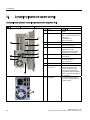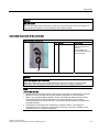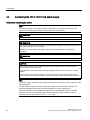
1
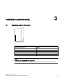
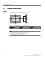
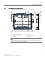
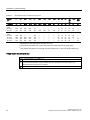
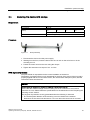
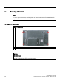
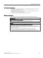
SIMATIC Industrial PC SIMATIC Panel PC 677B
1
Safety
______________
2
Delivery
______________
SIMATIC
Industrial PC
SIMATIC Panel PC 677B
Operating Instructions (Compact)
06/2008
A5E02217246-01
3
Installation / panel-mounting
______________
4
Connecting
______________
5
Commissioning
______________
6
Service and support
______________
Safety Guidelines
Safety Guidelines
This manual contains notices you have to observe in order to ensure your personal safety, as well as to prevent
damage to property. The notices referring to your personal safety are highlighted in the manual by a safety alert
symbol, notices referring only to property damage have no safety alert symbol. These notices shown below are
graded according to the degree of danger.
DANGER
indicates that death or severe personal injury will result if proper precautions are not taken.
WARNING
indicates that death or severe personal injury may result if proper precautions are not taken.
CAUTION
with a safety alert symbol, indicates that minor personal injury can result if proper precautions are not taken.
CAUTION
without a safety alert symbol, indicates that property damage can result if proper precautions are not taken.
NOTICE
indicates that an unintended result or situation can occur if the corresponding information is not taken into
account.
If more than one degree of danger is present, the warning notice representing the highest degree of danger will
be used. A notice warning of injury to persons with a safety alert symbol may also include a warning relating to
property damage.
Qualified Personnel
The device/system may only be set up and used in conjunction with this documentation. Commissioning and
operation of a device/system may only be performed by qualified personnel. Within the context of the safety notes
in this documentation qualified persons are defined as persons who are authorized to commission, ground and
label devices, systems and circuits in accordance with established safety practices and standards.
Prescribed Usage
Note the following:
WARNING
This device may only be used for the applications described in the catalog or the technical description and only
in connection with devices or components from other manufacturers which have been approved or
recommended by Siemens. Correct, reliable operation of the product requires proper transport, storage,
positioning and assembly as well as careful operation and maintenance.
Trademarks
All names identified by ® are registered trademarks of the Siemens AG. The remaining trademarks in this
publication may be trademarks whose use by third parties for their own purposes could violate the rights of the
owner.
Disclaimer of Liability
We have reviewed the contents of this publication to ensure consistency with the hardware and software
described. Since variance cannot be precluded entirely, we cannot guarantee full consistency. However, the
information in this publication is reviewed regularly and any necessary corrections are included in subsequent
editions.
이 기기는 업무용(A급) 전자파 적합기기로서 판매자 또는 사용자는 이 점을 주의하시기 바라며 가정 외의 지역에서 사용하는 것을 목적으로 합니다.
Siemens AG
Industry Sector
Postfach 48 48
90327 NÜRNBERG
GERMANY
A5E02217246-01
Ⓟ 06/2008
Copyright © Siemens AG 2008.
Technical data subject to change
Table of contents
1
Safety ........................................................................................................................................................ 5
2
Delivery...................................................................................................................................................... 7
3
4
5
6
2.1
Unpacking and checking the delivery ............................................................................................7
2.2
Device identification data ...............................................................................................................8
2.3
Product Documentation .................................................................................................................8
Installation / panel-mounting ...................................................................................................................... 9
3.1
Mounting depth of the device.........................................................................................................9
3.2
Permitted mounting positions.......................................................................................................10
3.3
Preparing the mounting cut-out....................................................................................................11
3.4
Securing the device with clamps..................................................................................................13
3.5
Securing with screws ...................................................................................................................14
Connecting .............................................................................................................................................. 17
4.1
Connection elements and operator controls ................................................................................18
4.2
Connecting the 120 V / 240 V AC power supply..........................................................................20
4.3
Connecting the (24 V) DC power supply .....................................................................................22
4.4
Connecting the Equipotential Bonding Circuit .............................................................................23
Commissioning ........................................................................................................................................ 25
5.1
Initial Startup ................................................................................................................................25
5.2
Setting up the language selection................................................................................................26
5.3
Setting the panel type ..................................................................................................................27
5.4
KeyTools (for key panel devices).................................................................................................28
5.5
On-screen keyboard (for touch panel device)..............................................................................29
Service and support................................................................................................................................. 31
SIMATIC Panel PC 677B
Operating Instructions (Compact), 06/2008, A5E02217246-01
3
1
Safety
CAUTION
In order to avoid substantial damage and for your own safety, note the safety instructions in
this documentation and in the operating instructions.
WARNING
Function test while installing the device in machines or execute systems
Following the results of a risk analysis, additional protection equipment on the machine or
the system is necessary to avoid endangering persons. With this, especially the
programming, configuration and wiring of the inserted I/O modules have to be executed, in
accordance with the safety performance (SIL, PL or Cat.) identified by the necessary risk
analysis. The intended use of the device has to be ensured.
The proper use of the device has to be verified with a function test on the system. This test
can detect programming, configuration and wiring errors. The test results have to be
documented and, if necessary, entered into the relevant documents that verify safety.
SIMATIC Panel PC 677B
Operating Instructions (Compact), 06/2008, A5E02217246-01
5
Safety
6
SIMATIC Panel PC 677B
Operating Instructions (Compact), 06/2008, A5E02217246-01
2
Delivery
2.1
Unpacking and checking the delivery
1. Please check the packaging material for transport damage upon delivery.
2. If any transport damage is present at the time of delivery, lodge a complaint at the
shipping company in charge. Have the shipper confirm the transport damage
immediately.
3. Unpack the device.
CAUTION
Do not lie the device on its back. This will avoid any damage to an optical drive which
may be present. Lie the front side on a soft surface to avoid damaging the front panel
USB port.
4. Keep the packaging material in case you have to transport the unit again.
NOTICE
The packaging protects the device during transport and storage. Therefore, never
dispose of the original packaging material!
5. Please keep the enclosed documentation in a safe place. You will need the
documentation when you start up the device for the first time.
6. Check the contents of the package for completeness and transportation damage. Check
for completeness using the enclosed scope of delivery list.
7. Should the contents of the package be incomplete or damaged, please inform the
responsible supply service immediately and fax us the enclosed form "SIMATIC IPC/PG
quality control report".
WARNING
Make sure that a damaged device is not installed nor put into operation.
8. Note the identification information (see chapter "Identification data of the device").
SIMATIC Panel PC 677B
Operating Instructions (Compact), 06/2008, A5E02217246-01
7
Delivery
2.2 Device identification data
2.2
Device identification data
Enter the identification data of the device into the table.
SVP number (on the type plate)
Order No.
Package with Windows 2000 / XP Professional:
"Microsoft Windows Product Key" from "Certificate of
Authenticity" (COA)
The label is attached to the device.
Ethernet address:
BIOS Setup (F2 key) under
"Main > Hardware Options > Ethernet Address"
2.3
Product Documentation
The detailed operating instructions for Panel PC 677B can be downloaded as a PDF file on
the Internet under the following address:
http://www.siemens.com/automation/service&support, article ID 25737077
8
SIMATIC Panel PC 677B
Operating Instructions (Compact), 06/2008, A5E02217246-01
3
Installation / panel-mounting
3.1
Mounting depth of the device
7
Panel PC with operator control units
Depth D
Key panel with 12" TFT
105 mm
Key panel with 15" TFT
124 mm
Touch panel with 12" TFT
123 mm
Touch panel with 15" TFT
121 mm
Touch panel with 17" TFT
130 mm
Touch panel with 19" TFT
130 mm
Note
Additional mounting depth with optical drive
The installation depth increases by 21 mm when an optical drive is installed in the device.
SIMATIC Panel PC 677B
Operating Instructions (Compact), 06/2008, A5E02217246-01
9
Installation / panel-mounting
3.2 Permitted mounting positions
3.2
Permitted mounting positions
Approval
Only certain mounting positions are approved for the device.
$
%
Figure 3-1
Mounting position
Table 3-1
Permissible deviations from the vertical mounting position
Temperature
Angle A
Angle B
to 45°C
20°
20°
Note
When mounting the device at an angle, note the following.
• Do not subject the device to mechanical stress.
• Operation of a DVD drive is not permitted.
10
SIMATIC Panel PC 677B
Operating Instructions (Compact), 06/2008, A5E02217246-01
Installation / panel-mounting
3.3 Preparing the mounting cut-out
3.3
Preparing the mounting cut-out
The following illustration shows the dimensions for the mounting cut-out.
$
/
$
/
/
/
6
6
/
/
6
/
/
6 6
/
/
/
/
6
6
/
PP
/
Figure 3-2
Drill holes for the screws and pressure points for the clamp screws
(1)
Drill hole for screw attachment
(4)
Clamp
(2)
Pressure points for clamp
(5)
RZ 120 in the seal area
(3)
Setscrews
(6)
Seal area
Note
Mounting dimensions can be read from the dimension overview or they can be transferred to
the cabinet from the mounting template supplied.
SIMATIC Panel PC 677B
Operating Instructions (Compact), 06/2008, A5E02217246-01
11
Installation / panel-mounting
3.3 Preparing the mounting cut-out
Table 3-2
Dimensions for the mounting cut-out in mm
Control
unit
L1
L2
L3 1)
L4 1)
L5
L6 2)
L7 2)
L8 2)
L9 2)
A1
A2
S1
S2
S3
S4
S53)
S63)
S73)
Tolerance
±1
+1
±0,2
±0,2
±0,5
±0,5
±0,5
±0,5
+1
±1
±1
±1
±1
±1
±1
Key
panel
12" TFT
15" TFT
450
450
290
321
465
465
235
279
112
112
—
186
—
135
—
25
—
165
16
16
10
17
78
51
78
51
56
56
—
—
Touch
panel
12" TFT
15" TFT
17" TFT
19" TFT
368
450
450
450
290
290
380
380
—
465
465
465
—
235
235
235
112
112
112
112
—
—
—
—
—
—
—
—
—
—
—
—
—
—
—
—
16
16
16
16
10
10
10
10
19
81
46
46
35
81
46
46
56
56
—
—
—
—
33
33
1)
M6 thread or drill holes with a diameter of 7 mm
2)
Cut-outs for the shafts of the insert strips are only necessary for 15" key panels.
3)
Two clamps necessary for vertically securing clamps for 17" and 19" touch panels only.
Preparing the mounting cut-out
Steps for preparing the mounting cut-out
12
1
Select a location suitable for mounting, taking into account the mounting position.
2
On the basis of the dimensions, check whether the required screw and pressure points on the
rear and the seal area are easily accessible after the completion of the mounting cut-out.
Otherwise the mounting cut-out is useless.
3
Complete the mounting cut-out in accordance with the dimensions.
SIMATIC Panel PC 677B
Operating Instructions (Compact), 06/2008, A5E02217246-01
Installation / panel-mounting
3.4 Securing the device with clamps
3.4
Securing the device with clamps
Requirement
Accessories
Display
Clamp
12"
15"
17"
19"
6x
6x
8x
8x
The clamps are provided with the control unit.
Tool
2.5 mm hexagonal spanner
Procedure
Figure 3-3
Clamp assembly
1. Disconnect the device from the power supply.
2. Working from the front, insert the device into the 19" rack on the swivel arm or in the
mounting cut-out.
3. Fasten the control unit from the rear using the clamps.
4. Tighten the setscrews to a torque of 0.4 - 0.5 Nm.
IP65 degree of protection
The plant builder is responsible for the correct installation of the device.
The degree of protection IP65 is only guaranteed for the front of the device if the ring seal is
properly applied with the correct size of cutout, the unit has been clamped in place, and the
instructions below are observed.
NOTICE
Control cabinet installation: Material strength at the mounting cut-out
Ensure that the material strength at the mounting cut-out is a minimum of 2 mm and a
maximum of 6 mm. Please follow the specifications for the dimensions in the "Preparing the
mounting cut-out" section.
The degrees of protection are only guaranteed when the following is observed:
• The surface plane deviation of the mounting cut-out in relation to the external
dimensions of the control unit amounts to ≤ 0.5 mm when the control unit is mounted.
SIMATIC Panel PC 677B
Operating Instructions (Compact), 06/2008, A5E02217246-01
13
Installation / panel-mounting
3.5 Securing with screws
3.5
Securing with screws
Note
Securing with screws is not possible with the 12" touch panel variant. To secure the 17" and
19" touch panel with screws, backing plates with order number 6AV7672-8KE00-0AA0 are
required on the front.
Drill holes in the control unit
Steps for drilling holes
1
Drill holes (Ø approx. 2.5 mm) from the rear in the four recesses of the control unit
2
Drill these holes with a diameter of Ø 5.5 mm for M5 and a Ø 6.5 mm for M6.
3
Deburr the holes from the front of the control unit
NOTICE
Risk of damage
Ensure that no metal cuttings enter the device when the holes are drilled. Cover the device
with film or when drilling, use removal by suction.
14
SIMATIC Panel PC 677B
Operating Instructions (Compact), 06/2008, A5E02217246-01
Installation / panel-mounting
3.5 Securing with screws
Drill holes in the mounting unit
1. Drill the holes at the prepared mounting cut-out according to the information for L3 and
L4. (see Chapter "Mounting cut-out" )
2. Working from the front, insert the device into the 19" rack on the swivel arm or in the
mounting cut-out of the control cabinet.
3. Secure the control unit by inserting suitable screws and nuts
IP54 degree of protection
The IP54 degree of protection is guaranteed for mounting together with the ring seal.
CAUTION
Observe the panel seal when mounting
Ensure you do not damage the panel seal when mounting the device.
NOTICE
Control cabinet installation: Material strength at the mounting cut-out
Ensure that the material strength at the mounting cut-out is a minimum of 2 mm and a
maximum of 6 mm. Please follow the specifications for the dimensions in the "Preparing the
mounting cut-out" section.
The degrees of protection are only guaranteed when the following is observed:
• The surface plane deviation of the mounting cut-out in relation to the external
dimensions of the control unit amounts to ≤ 0.5 mm when the control unit is mounted.
SIMATIC Panel PC 677B
Operating Instructions (Compact), 06/2008, A5E02217246-01
15
Installation / panel-mounting
3.5 Securing with screws
16
SIMATIC Panel PC 677B
Operating Instructions (Compact), 06/2008, A5E02217246-01
Connecting
SIMATIC Panel PC 677B
Operating Instructions (Compact), 06/2008, A5E02217246-01
4
17
Connecting
4.1 Connection elements and operator controls
4.1
Connection elements and operator controls
Connection and Operator Control Components of the Computer Unit
Locations of connection and operator control components
Pos
Name
Description
(1)
PCI (e)
2 slots for PCI expansion
module
(2)
DVI/VGA
DVI/VGA socket for
CRT or LCD monitor with DVI
interface or
VGA monitor via
DVI/VGA adapter
(3)
Compact Flash
Slot for Compact Flash card
(4)
COM 1
Serial interface (RS232)
9-pin D-sub connector
(5)
USB
4 USB 2.0 interfaces
(2 interfaces can be
simultaneously used as high
current (500 mA) outputs)
(6)
Ethernet
2 RJ45 connections for
10/100 Mbps
(7)
PROFIBUS DP/MPI
MPI interface (RS485,
electrically isolated),
9-pin D-sub plug
(8)
On / Off switch
-
(9)
100 - 240 V AC
or 24 V DC
Connection for AC or DC power
supply (depending on the
product variant, the figure
shows the AC power plug)
The relevant angle is included
with the device for interlocking
the connector.
(10)
PROFINET
CP 1616 onboard interface,
three RJ45 sockets (optional
product version)
18
SIMATIC Panel PC 677B
Operating Instructions (Compact), 06/2008, A5E02217246-01
Connecting
4.1 Connection elements and operator controls
NOTICE
On / Off switch
The On / Off switch does not disconnect the device from the mains. When the switch is in
the 0 position, the device is still connected to the auxiliary voltage.
Connection components of the control unit
USB connection control unit
Pos
Name
Description
(1)
USB
1 connection
USB 2.0 high current /
500 mA
under sealed cover
(not available with every
product variant).
NOTICE
Ensuring degree of protection P65
When the sealed cover over the USB interface is removed in order to connect a USB
component, the IP65 degree of protection for the device is no longer guaranteed.
Note
Use of USB devices
• Wait at least ten seconds between removal and reconnection of USB devices. This also
applies to control units with touch screen panels, especially for touch operation.
• When using standard USB peripherals, bear in mind that their EMC immunity level is
frequently designed for office applications only. These devices may be used for
commissioning and servicing. However, only industry-standard devices are allowed for
industrial operation.
• Peripherals are developed and marketed by individual vendors. The respective
manufacturers offer support for the peripherals. Moreover, the terms of liability of the
individual vendors or suppliers apply here.
SIMATIC Panel PC 677B
Operating Instructions (Compact), 06/2008, A5E02217246-01
19
Connecting
4.2 Connecting the 120 V / 240 V AC power supply
4.2
Connecting the 120 V / 240 V AC power supply
Note before connecting the device
Note
The varying voltage power supply module is designed for operation on 120 / 240 V AC
networks. The setting of the voltage range takes place automatically.
WARNING
Do not connect or disconnect power and data cables during thunderstorms.
WARNING
The device is designed for operation on grounded power supply networks (TN networks to
VDE 0100, Part 300, or IEC 60364-3).
Operation on ungrounded or impedance-grounded power networks (IT networks) is
prohibited.
WARNING
The permitted nominal voltage of the device must conform with local mains voltage.
CAUTION
The mains connector must be disconnected to fully isolate the device from the mains.
Ensure easy access to this area.
A master mains disconnect switch must be installed if the device is mounted in a switch
cabinet.
Always ensure free and easy access to the power inlet on the device or that the safety
power outlet of the building installation is freely accessible and located close to the device.
Note
The power supply contains an active PFC (Power Factor Correction) circuit to conform to the
EMC guidelines.
Uninterruptible AC power systems (UPS) must supply a sinusoidal output voltage in the
normal and buffered mode when used with SIMATIC PCs with an active PFC.
UPS characteristics are described and classified in the standards EN 50091-3 and IEC
62040-3. Devices with sinusoidal output voltage in the normal and buffered mode are
identified with the classification "VFI-SS-...." or "VI-SS-....".
20
SIMATIC Panel PC 677B
Operating Instructions (Compact), 06/2008, A5E02217246-01
Connecting
4.2 Connecting the 120 V / 240 V AC power supply
Localized information
For countries other than the USA and Canada:
240 V supply voltage
This device is equipped with a safety-tested power cable which may only be connected to a
grounding outlet. If you choose not to use this cable, you must use a flexible cable of the
following type: Min 18 AWG conductor cross-section and 15-A / 250-V shockproof connector.
The cable set must be compliant with the safety regulations and stipulated IDs of the country
where the system is to be installed.
For the USA and Canada:
For the United States and Canada, a CSA or UL-listed power cord must be used.
The connector must be compliant with NEMA 5-15.
120 VAC power supply
Use a flexible power cord which is approved to UL and CSA, and which has the following
features: Type SJT with three leads, min. 18 AWG conductor cross-section, max. 4.5 m in
length and parallel ground contact connector 15 A, min. 125 V.
240 VAC power supply
Use a flexible power cord which is approved to UL and CSA, and which has the following
features: Type SJT with three conductors, min. 18 AWG conductor cross-section, max.
length 4.5 m, and tandem grounded connector 15 A, min. 250 V.
Connecting
How to connect the device to the 120 V AC / 240 V AC power supply
1
Ensure that the On/Off switch is in '0' position
(Off) when you plug in the power cord in order
to avoid unintentional startup of the device.
2
Connect the equipotential bonding.
3
Insert the power cable in the electrical socket.
4
Fasten the cable with the supplied power plug
latch, if necessary.
SIMATIC Panel PC 677B
Operating Instructions (Compact), 06/2008, A5E02217246-01
21
Connecting
4.3 Connecting the (24 V) DC power supply
Power consumption
Depending on the size of the display and taking into account 15 W per PCI slot, the power
consumption for devices with 12" and 15" operator control units is max. 140 W, and with 17"
and 19" operator control units it is max. 163 W.
4.3
Connecting the (24 V) DC power supply
Note before connecting the device
WARNING
Only connect the device to 24 V DC power supply systems which meet the requirements of
a safe extra-low voltage (SELV); in addition, a protective conductor must be connected.
The conductors must withstand the short-circuit current of the 24 V DC power source, so
that a short-circuit will not damage the cable. Only connect cables with a minimum crosssection of 1.3 mm2 (AWG16) and a maximum cross-section of 3.3 mm2 (AWG12).
NOTICE
The 24 V DC power supply must match the power consumption of the device (see
Specifications).
Connecting
Steps for connecting the device to the 24 V DC power supply
1
Ensure that the On/Off switch is in the '0'
(OFF) position to prevent unintentional startup
of the device when connecting it to the 24 V
power supply.
2
Switch off the 24 V DC power supply.
3
Attach the DC connector.
(1) 24 V DC
(2) ground
(3) protective conductor
22
SIMATIC Panel PC 677B
Operating Instructions (Compact), 06/2008, A5E02217246-01
Connecting
4.4 Connecting the Equipotential Bonding Circuit
4.4
Connecting the Equipotential Bonding Circuit
A low-resistance ground connection ensures that interference signals generated by external
power supply cables, signal cables or cables to the I/O modules are safely discharged to
ground.
The equipotential bonding connection of the device is located underneath the device and is
identified by the following symbol:
Figure 4-1
Equipotential Bonding
Connecting the Equipotential Bonding Circuit
You require a TORX T20 screwdriver to connect the equipotential bonding conductor.
Steps for connecting the equipotential bonding
(1)
Connect the equipotential bonding connection (M4 thread) (1)
on the device (large surface, large-area contact) with the
central grounding point of the control cabinet.
The minimum permissible cross-section is 5 mm2.
SIMATIC Panel PC 677B
Operating Instructions (Compact), 06/2008, A5E02217246-01
23
Connecting
4.4 Connecting the Equipotential Bonding Circuit
24
SIMATIC Panel PC 677B
Operating Instructions (Compact), 06/2008, A5E02217246-01
Commissioning
5.1
5
Initial Startup
Configuring the operating system
Note
Requirements for initial start-up
Before switching on the computer for the first time, check that the equipotential bonding is
connected and that all connecting cables are plugged in correctly. Also ensure that a USB
keyboard and a USB mouse are connected to the PC.
When the computer starts up for the first time, the Windows 2000 / Windows XP Professional
/ Windows Vista operating system on the hard disk is configured automatically. Procedure:
1. Connect the device to the power supply.
– The module carries out a self-test. The following message appears:
Press <F2> to enter Setup or <ESC> to show Boot menu
2. Wait for the message to disappear.
3. Follow the instructions on the screen.
NOTICE
The device may not be switched off at any time during the installation process.
Do not change the default BIOS settings, otherwise the operating system setup may
become corrupted.
4. When you have entered all necessary information and the operating system setup is
completed, the PC is reboots automatically and the user interface of the respective
operating system is displayed.
Note
System startup can take longer than usual for the initial commissioning.
When you switch on the PC now, the user interface of the Windows 2000 / Windows XP
Professional / Windows Vista operating system is automatically opened when the startup
routine is completed.
SIMATIC Panel PC 677B
Operating Instructions (Compact), 06/2008, A5E02217246-01
25
Commissioning
5.2 Setting up the language selection
Note
Windows logon
If you have assigned an administrator password, you must log in before you can access the
operating system. With touch devices, you can log on using a virtual on-screen keyboard.
Note
To prevent data loss, it is advisable to create an image of your system partition after initial
commissioning.
Switching off the device
If you work with Windows 2000 / Windows XP Professional / Windows Vista, always shut
down the PC with the command "Start > Shutdown".
5.2
Setting up the language selection
The Multilanguage User Interface (MUI) allows you to set up the Windows 2000 / Windows
XP Professional / Windows Vista menus and dialogs for additional languages.
Windows 2000 and Windows XP
The default language setting of your MUI installation is English with US keyboard layout. You
can change the language in the Control Panel. Select:
"Start > Settings > Control Panel > Regional and Language Options", "Languages" tab, "Language
used in menus and dialogs" field.
For the "Regional and Language Options" set the default as "non-Unicode programs" under
"Advanced" in addition to the language for menus and dialogs.
Windows Vista
When shipped, Windows Vista is installed with English menus and dialogs. You can change
this in the Control Panel with the "Regional and Language Options" or "Time and Date"
dialogs.
26
SIMATIC Panel PC 677B
Operating Instructions (Compact), 06/2008, A5E02217246-01
Commissioning
5.3 Setting the panel type
5.3
Setting the panel type
After the device is restarted, different dialogs appear on the screen. Drivers and applications
can be installed from these dialogs.
1. In the "Panel Wizard" dialog, click the type of panel that corresponds to your device.
Figure 5-1
Panel type
2. Follow the instructions on the screen.
SIMATIC Panel PC 677B
Operating Instructions (Compact), 06/2008, A5E02217246-01
27
Commissioning
5.4 KeyTools (for key panel devices)
5.4
KeyTools (for key panel devices)
SIMATIC KeyTools is one selection of the applications for your Panel PC. These applications
allow you to adapt key codes that are sent by the key panel of the control unit. SIMATIC
KeyTools consists of the following applications:
● Key code table: Loading and editing of key code tables
● WinCC hotkey function: WinCC hotkey function activation and deactivation
● Security features: Lock function that prevents two function keys from being activated
simultaneously. This prevents incorrect operations and undefined states of the user
program.
Note
For a detailed description of the SIMATIC KeyTools, refer to the help menu and the
application description on the "Documentation and Drivers" CD.
Calling up KeyTools
1. Select "Start > Settings > Control Panel > SIMATIC KeyTools".
2. Select the desired application and follow the instructions on the screen.
NOTICE
Malfunctions of the user software
For security reasons always use the "Security features". If you deactivate it
nevertheless, serious malfunctions of the user software may occur when the additional
function keys and softkeys F11 to F20 and S1 to S16 are used or if own key code tables
are used.
28
SIMATIC Panel PC 677B
Operating Instructions (Compact), 06/2008, A5E02217246-01
Commissioning
5.5 On-screen keyboard (for touch panel device)
5.5
On-screen keyboard (for touch panel device)
You can operate the device by means of a virtual screen keyboard. You can use it to enter
the characters directly on the touch panel or with an externally connected mouse.
Call "Touch input"
Start the "Touch input" application on the desktop. The screen keyboard is displayed.
(1) Button for language selection: German, English, Italian, Spanish, French
SIMATIC Panel PC 677B
Operating Instructions (Compact), 06/2008, A5E02217246-01
29
Commissioning
5.5 On-screen keyboard (for touch panel device)
30
SIMATIC Panel PC 677B
Operating Instructions (Compact), 06/2008, A5E02217246-01
Service and support
6
Local information
If you have questions about the products described in this document, you can find help at:
http://www.siemens.com/automation/partner
Technical documentation for SIMATIC products
Further documentation for SIMATIC products and systems can be found at:
http://www.siemens.com/simatic-tech-doku-portal
Easy Shopping at the Mall
Catalog & online ordering system http://www.siemens.com/automation/mall
Training
All the training options are listed at: http://www.siemens.com/sitrain
Find a contact at: Phone: +49(911) 895-3200
Technical support
Tel +49 180 5050 222
Fax +49 180 5050 223
http://www.siemens.com/automation/csi/service
A Web form for Support Request can be found at:
http://www.siemens.com/automation/support-request
When you contact the customer support, please have the following information for the
technician on hand:
● BIOS version
● Order No. (MLFB) of the device
● Installed additional software
● Installed additional hardware
Online support
Information about the product, Support and Service, right through to the Technical Forum,
can be found at: http://www.siemens.com/automation/service&support
SIMATIC Panel PC 677B
Operating Instructions (Compact), 06/2008, A5E02217246-01
31
Service and support
After-sales information system for SIMATIC PC / PG
Information about contacts, drivers, and BIOS updates, FAQs and Customer Support can be
found at: http://www.siemens.com/asis
32
SIMATIC Panel PC 677B
Operating Instructions (Compact), 06/2008, A5E02217246-01