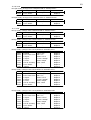
1
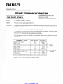
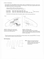
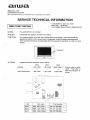
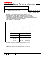
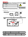
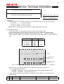
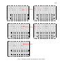
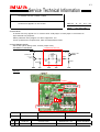
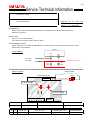
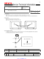
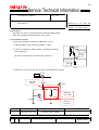
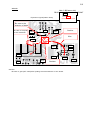
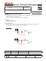
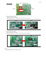
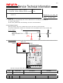
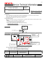
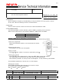
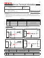
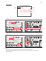
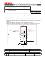
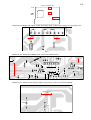
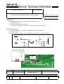
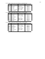
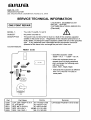
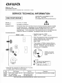
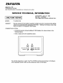
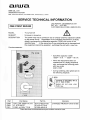
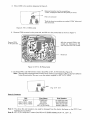
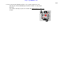
http://getMANUAL.com
1/1
Service Technical Information
MODEL NO.
TV −F2000 / F2400
SUBJECT
REF.No. :G − 99 − 076 − E0
Notes on repairing flat CRT TV set
DATE
:02. MAR. 2000
<CONTENTS>
Pay attention to the following notes when repairing flat CRT a TV set.
When repairing a unit, DO NOT LEAVE the degaussing cable disconnected.
Conventional TV sets allow repairing work with a degaussing cable removed.
When repairing a TV set with flat CRT, however, the instruction below must be followed.
The instruction is provided on the service manual also.
Make this known to all staff concerned.
Notes on repairing:
DO NOT turn on the power of a TV set with a flat CRT when a degaussing coil is removed.
Be sure to connect a dummy load when removing a degaussing coil.
Scheme 1: Use another degaussing coil to be connected for repairing.
Scheme 2: Use a 6.8 Ω, 20W resistor, as the jig to be connected to the connector of
degaussing coil.
Turning on the power of a unit with neither degaussing coil or dummy load results in
opening a fixed resistor R848, which is inserted in parallel to the degaussing coil.
The following shows relations between the models concerned and the cement −resistors:
Model name
R848
Type
TV −F21ST1
33 Ω/2W
cement resistor
TV −F25ST1
TV −F2400
27 Ω/2W
cement resistor
TV −F2000
56 Ω/2W
cement resistor
If the resistor opens, noises appear in horizontal directions on screen.
Also pay attentions to information about the flat CRT models to be released in the future.
Component values of the dummy resistors will be announced as occasion arises, and will be
contained in the service manual. Always take notice of the information.
G
R
Code No.
Access Code
Modified Ser. No.
Parts Schedule
−
−
−
−
−
−
1/1
Service Technical Information
MODEL NO.
SUFFIX
TV −F2000 / F2400
U/U
SUBJECT
REF.No. :G − 99 − 076 − E1
Notes on repairing
DATE
:18. FEB. 2002
REVISION : Amended the SUBJECT and the <CONTENTS>.
<CONTENTS>
Pay attention to the following notes when repairing the TV− F2400/F2000.
Do not leave the degaussing cable disconnected when repair a unit.
Conventional TV sets allow repairing work with a degaussing cable removed.
Turning on the power of a TV− F2400 / F2000 with neither degaussing coil results in breaking a
cement resistor which is inserted in parallel to the degaussing coil.
Be sure to connect a dummy load when removing a degaussing coil.
Scheme 1 :Use another degaussing coil to be connected for repairing.
Scheme 2 :Use a 6.8Ω − 20W resistor, as the jig to be connected to the connector of
degaussing coil.
Turning on the power of a unit with neither degaussing coil or dummy load results in
opening a fixed resistor which is inserted in parallel to the degaussing coil.
The following shows relations between the models concerned and the cement −resistors.
Model
Ref No.
Value
Parts Code
Affected Serial No.
TV −F21ST1
R848
56W/2W
87 − A00 −659 −010
S ∗∗∗∗9C ∗∗∗∗∗~
TV −F25ST1
R848
27W/2W
87 − A00 −655 −010
S ∗∗∗∗9C ∗∗∗∗∗~
TV −F2400
R801
27W/2W
87− A00 −661 −010
All
TV −F2000
R801
56W/2W
87− A00 −665 −010
All
Note :The cement −resistor is not installed, if the serial number of unit is not included in
table above.
If the resistor opens, noises may appear in horizontal directions on screen.
G
R
Code No.
Access Code
Modified Ser. No.
Parts Schedule
−
−
−
−
−
−
1/1
Service Technical Information
MODEL NO.
TV −CN143 / CN203
SUBJECT
REF.No. :G − A0 − 032 − E0
The screen is too dark
DATE
:31. MAY. 2000
<CONTENTS>
The screen voltage falls down due to an abnormality of the capacitor C901 thereby causing
the screen to become dark.
Take the following countermeasure when this problem is pointed out.
<COUNTERMEASURE>
Replace the capacitor C901.
∗ Always make sure to use the specified part because the manufacturer of this part has been
changed.
NK.PWB
C901
Parts Name
Parts Code
CAP,CER 1000P −2KB
87−016−037 −060
Ref.
Parts Code
Description
Remarks
C901
87− 016− 037− 060
CAP,CER 1000P −2KB
−
G
R
Code No.
Access Code
Modified Ser. No.
Parts Schedule
−
−
−
−
S ∗∗∗∗03∗∗∗∗∗
−
1/1
Service Technical Information
MODEL NO.
TV −AT215
SUBJECT
REF.No. :G − A0 − 035 − E0
The remote control is not effective
DATE
:05. JUN. 2000
<CONTENTS>
In this set, after successive operations of changing the channel are made using the remote
control, there are times when the remote control becomes ineffective.
Please take the following countermeasures for such sets.
Further, although this condition gets recovered when the AC cord of the main unit is removed
and then inserted again in to the power socket, the same condition occurs again if the above
operation is made again.
<COUNTERMEASURE>
Please replace the component with the one specified below.
∗ Take care about the differences between the regional models.
A: IC, ST6387−OTP 6373
Rumania Version
The mark "R" is present on the top surface of
the IC.
B: IC, ST6387−OTP 6331
Poland Version
There are marks of two white dots on the top
surface of the IC.
Method of discriminating between the microcomputer IC of different regional models
A: Rumania Version
B: Poland Version
Marking of two white dots
Marking of the "R" mark
Ref.
Parts Code
Description
Remarks
IC1
IC1
87−JB1 −626 −010
87−JB1 −627 −010
IC, ST6387− OTP 6373
IC, ST6387 − OTP 6331
for Romania version
for Poland, Czech, Slovakia
G
R
Code No.
Access Code
Modified Ser. No.
Parts Schedule
−
−
−
−
−
20.AUG.2000
1/1
Service Technical Information
MODEL NO.
TV −C202
TV −C202S
SUBJECT
REF.No. :G − A0 − 117 − E0
No power
DATE
:02. MAR. 2001
<CONTENTS>
No power due to open IC PROTECTOR (ICP,PR 801) caused by a rush current.
<COUNTERMEASURE>
Replace the IC Protector (PR801 1.5A)with one that has higher current capacity(4A).
SCHEMATIC DIAGRAM
IC Protector
Power Supply
3
T602
PR801
1.5A 4A
IC804
1
1
12V REG
E15
2
C825
WIRING
MAIN C.B Pattern Side
Expansion Figure
R
E
A
R
F
R
O
N
T
PR801
T602
PR801
T602
Q602
Ref.
Parts Code
Description
Remarks
PR801
87 − A90− 094 −080
PROTECTOR,4A 491SERIES 60V
−
G
R
Code No.
Access Code
Modified Ser. No.
Parts Schedule
−
−
−
−
−
−
1/2
Service Technical Information
MODEL NO.
TV −SA2151/A2118/A2110/A2018/A2010
SUBJECT
REF.No. :G − A0 − 125 − E0
Distinction Switch setting up procedure
DATE
:10. APR. 2001
<CONTENTS>
Setup procedure for Distinction Switch was not described in the service manuals below.
TV −SA2151
09 − 007 − 420−8S1
TV −A2110 / A2118 09 −007 −416 −7S3
TV −A2010 / A2018 09 −007 −420 −5S1
Please refer to the following procedure when setting Distinction Switches.
<COUNTERMEASURE>
1. Press TEST key of a Jig remote control and set to the AGING mode.
2. Press SYSTEM key of a jig remote control and set to the Distinction Switch mode.
3. Make sure the lower part in the upper row on the screen 1:KE 1 ∼ 8:SH4, are shown in
red as the below table. If not press the numeric key to make the items in question become
red.
Model Name
TV −SA2151
TV −A2118
TV −A2110
TV −A2018
TV −A2010
Fig.1 Items to be
1
2
3
4
:
:
:
:
K
K
I
I
E
E
N
N
1
2
DO1
DO2
0
1
1
0
1
1
1
1
1
0
2
0
1
2
1
3
1
1
3
1
4
0
1
4
0
5
0
1
5
0
Item
Key
SH3
7
SH2
6
KE2
2
SH2
6
KE2
2
selected by model
5
6
7
8
:
:
:
:
S
S
S
S
H
H
H
H
1
2
3
4
6
0
1
6
1
7
0
1
7
0
8
1
1
8
0
9
1
1
9
0
A
1
1
A
1
Red
B
1
1
B
1
C
0
1
C
0
D
0
1
D
0
E
0
1
E
0
Address 0∼ F
Date 0 ∼F
F
1
1
F
0
Address 10∼1F
Date 10∼ F
(Example : TV− SA2151)
Fig.2 Screen shot on the distinction switch set up mode
4. Check to see if the data of address 0-1F match the Fig3 (next page) or not.
If not, amend them as follows:
CHANNEL UP/DOWN Select appropriate data (selected data appear in red)
VOLUME UP/DOWN Change value (0 or 1)
5. After data input and/or confirmation is completed, Press TEST key to go back to the
AGING mode.
G
R
Code No.
Access Code
Modified Ser. No.
Parts Schedule
−
−
−
−
−
−
2/2
1
2
3
4
:
:
:
:
K
K
I
I
E
E
N
N
1
2
DO1
DO2
0
1
1
0
1
1
1
1
1
0
2
0
1
2
1
3
1
1
3
1
4
0
1
4
0
5
0
1
5
0
5
6
7
8
:
:
:
:
S
S
S
S
H
H
H
H
1
2
3
4
6
0
1
6
1
7
0
1
7
0
8
1
1
8
0
9
1
1
9
0
A
1
1
A
1
Red
B
1
1
B
1
C
0
1
C
0
D
0
1
D
0
E
0
1
E
0
1
2
3
4
:
:
:
:
F
1
1
F
0
K
K
I
I
E
E
N
N
1
2
DO1
DO2
0
1
1
0
0
1
0
1
1
0
2
0
1
2
1
3
1
1
3
1
TV −SA2151
1
2
3
4
:
:
:
:
K
K
I
I
E
E
N
N
1
2
D
DO2
0
1
1
0
0
1
1
1
1
0
2
0
1
2
1
3
1
1
3
1
4
0
1
4
0
5
0
1
5
0
:
:
:
:
K
K
I
I
E
E
N
N
1
2
D
DO2
0
1
1
0
0
1
0
1
1
0
2
0
1
2
1
3
1
1
3
1
4
0
1
4
0
5
0
1
5
0
5
0
1
5
0
:
:
:
:
S
S
S
S
H
H
H
H
1
2
3
4
6
0
1
6
1
7
0
1
7
0
8
1
1
8
0
9
1
1
9
0
A
1
1
A
1
5
6
7
8
:
:
:
:
S
S
S
S
H
H
H
H
1
2
3
4
6
0
1
6
1
7
0
1
7
0
8
1
1
8
0
9
1
1
9
0
A
1
1
A
1
Red
B
1
1
B
1
C
0
1
C
0
D
0
1
D
0
E
0
1
E
0
F
0
1
F
0
1
2
3
4
:
:
:
:
K
K
I
I
E
E
N
N
1
2
D
DO2
0
1
1
0
0
1
0
1
1
0
2
0
1
2
1
3
1
1
3
1
4
0
1
4
0
5
0
1
5
0
5
6
7
8
:
:
:
:
S
S
S
S
H
H
H
H
1
2
3
4
6
0
1
6
1
7
0
1
7
0
8
1
1
8
0
9
1
1
9
0
A
1
1
A
1
TV− A2010
5
6
7
8
:
:
:
:
S
S
S
S
H
H
H
H
1
2
3
4
6
0
1
6
1
7
0
1
7
0
8
1
1
8
0
9
1
1
9
0
A
1
1
A
1
Red
B
1
1
B
1
C
0
1
C
0
D
0
1
D
0
E
0
1
E
0
F
0
1
F
0
TV− A2018
Fig.3
B
1
1
B
1
C
0
1
C
0
D
0
1
D
0
E
0
1
E
0
F
0
1
F
0
B
1
1
B
1
C
0
1
C
0
D
0
1
D
0
E
0
1
E
0
F
0
1
F
0
TV− A2110
TV −A2118
1
2
3
4
4
0
1
4
0
5
6
7
8
Distinction switch set up data for each model
1/1
Service Technical Information
MODEL NO.
TV −F2000 / F2100 / F2400 / F2500
SUBJECT
REF.No. :G − A1 − 011 − E0
Vertical line appears on the screen
DATE
:06. JUN. 2001
<CONTENTS>
A vertical line may appear on TV screen when VCD player or DVD player is connected to
input terminal for playback.
Same problems rarely happen on other equipment, too.
If such problems are experienced, take countermeasure below.
<COUNTERMEASURE>
Add a filter (when fitting L402, remove jumper wire).
SCHEMATIC DIAGRAM
Additional Circuit
L402
Q413
12µH
VIDEO−IN
VIDEO−OUT
C461
27PF
R463
Q412
C462
39PF
R462
C463
100PF
R464
WIRING
C463:100pF
C462:39pF
L402:12µH
C461:27pF
Ref.
Parts Code
Description
Remarks
−
SV− T00− 117− 01J
KIT,TV− F2100/F2500 V NOISE
−
G
R
Code No.
Access Code
Modified Ser. No.
Parts Schedule
−
−
−
−
S ∗∗∗∗ 12∗∗∗∗∗∼
13.JLY.2001
1/1
Service Technical Information
MODEL NO.
TV −SE1430 / SE2130 / C1400
SUBJECT
REF.No. :G − A1 − 017 − E0
Revised set up procedure
DATE
:11. JUN. 2001
<CONTENTS>
For betterment of the "step by step instructions" on the SET UP procedure in the Service Manuals,
we add one more step as described below.
Correction(add the red colored sentence)
Step "No.3" shown in red to be incerted to the procedure.
1. Use the numeric keys on the remote control to set the receiving channel to Pr91.
2. Set Sharpness on the Picture Menu screen to 0.
3. Press MENU button on the remote control twice to back to the normal mode.
(Channel Pr91 appears on the screen).
4. Press the buttons on remote control in the following order:
Skip(R)
Move(G)
Menu
The following menu will appear on the TV screen (the menu can be seiched by the " P / "
button on the remote control).
5. To terminate the menu screen, press the MENU button on the remote control,or the power
button on the TV or remote control.
<NOTE>
Pressing three button described in the process 4 above must be done with a second,
or it will not get into the Service Mode.
G
R
Code No.
Access Code
Modified Ser. No.
Parts Schedule
−
−
−
−
−
−
1/1
Service Technical Information
MODEL NO.
TV −SE141 / SE211
SUBJECT
REF.No. :G − A1 − 024 − E0
Audio malfunction
DATE
:14. JUN. 2001
<CONTENTS>
Noise enters into the data line(SDA/SCK) of IC404(volume controller) and causes the
following symptoms.
<SYMPTOM>
Sound cuts out intermittently.
One channel becomes louder than the other.
<COUNTERMEASURE>
Add a capacitor to the data line(SDA/SCK) of IC404(volume controller) and compose a noise
filter(Lands are available).
IC404
Circuit diagram
SDA
SCK
9
10
IC1 5pin
IC1 4pin
Add C474 and C475
C475
100pF
C474
100pF
Pattern diagram
AUDIO PWB
Enlarged diagram
IC404
IC404
10 9
Apprecable section
C475/100pF
C474/100pF
CN404
Ref.
Parts Code
Description
Remarks
C475,C474
87− 010− 322− 080
C− CAP,S 100P− 50 J CH GR
−
G
R
Code No.
Access Code
Modified Ser. No.
Parts Schedule
−
−
−
−
−
−
1/1
Service Technical Information
MODEL NO.
SUFFIX
TV− A2110 / A2118 / SA2151
KER(A2110),SH(A2118)
SHR(SA2151)
SUBJECT
REF No :G − A1 − 031 − E0
Black marking on screen
DATE
:30. JUL. 2001
<CONTENTS>
Spot remains at power off and black marking may happen on screen.
Take the necessary countermeasure for any pointed symptom corrective countermeasure 1.
<SYMPTOM>
Black marking appear as shown below.
Appearing point defers according to the set.
Black marking
<COUNTERMEASURE>
1. Replace C317(330 µF/16V) to 1000 µF/16V(87 −A10 −730 −080) regardless the symptom.
2. If already CRT burned in, replace to new CRT.
IC301
H − VCC
28
Old : 330µF/16V
C317
New : 1000µF/16V
Ref.
Parts Code
Description
Remarks
C317
87 −A10−730 −080
CAP,E 1000 − 16V SMG
−
G
R
Code No.
Access Code
Modified Ser. No.
Parts Schedule
−
−
−
−
−
10.SEP.2001
http://getMANUAL.com
1/2
Service Technical Information
MODEL NO.
SUFFIX
TV −AN2110 / AN2010
NH / NH
SUBJECT
REF No :G − A1 − 040 − E0
No power on
DATE
:24. AUG. 2001
<CONTENTS>
No power on due to horizontal output transistor Q601 failure.
Take the following countermeasure in this case.
<COUNTERMEASURE>
Prevent the damage of Q601 by adding the curcuit.
1. Replace Q601 after confirming PR801 is open.
plus side
2. Connect condenser, diode, resistor, and wire according
to the drawing 1.
Condenser
Diode
Be care to the direction of diode and condensor.
cathode side
Resistor
Wire
Fig1
3. Attach the circuit 2 to the rear of main board.(Refer next page)
H−OUT
IC301
32
Add D615
1SS133
R342
Q404
coutermeasure circuit
Add R625
6.8K−1/8W
R608
Q602
H−AMP
Add C617
47µF/16V
Ref.
Parts Code
Description
Remarks
−
SV− T00− 118− 010
KIT,ZJA− 19 No Power
−
G
R
Code No.
Access Code
Modified Ser. No.
Parts Schedule
−
−
−
−
−
25.SEP.2001
2/2
WIRING
Main C.B(Pattern side)
REAR
Expansion figure(Pattern Side)
FRONT
IC301
countermeasure circuit
Be care to the
direction of diode
Be care to the polar
of the condenser
D312
R342
Cushion
R344
Wire
D311
C453
R455
Q454
HT401
EY64
D412
Q404
C306
Q412
IC401
Resistor
<NOTE>
Be sure to glue (KE − 3490) after putting the semiconductor to the board.
1/2
Service Technical Information
MODEL NO.
SUFFIX
TV− C1400
KY,EZY,KHY
SUBJECT
REF No :G − A1 − 052 − E1
OSD does not display, standby LED does not light
DATE
:08. NOV. 2001
REVISION : Modified Ser. No. had corrected.
<CONTENTS>
It may happen that " OSD does not display, standby LED does not light " as the flux causes to
change the capacity of CC709,CC723.
In such a case, take the following corrective countermeasure.
<SYMPTOM>
OSD does not display
Standby LED does not light
<COUNTERMEASURE>
By replacing the condenser CC709,CC723 from chip type to AXIAL type, the effect of flux
reduces.(Please refer the next page for actual installation)
Circuit diagram
I701
RC704
PXFM 36
CC705
CC723
Countermeasure part
I701
RC706
MCFM 23
CC709
CC708
Countermeasure part
Ref.
Parts Code
Description
Remarks
CC709,CC723
87 −A11 −073 −080
CAP,TC U 22P −50J CH
G
R
Code No.
Access Code
Modified Ser. No.
Parts Schedule
−
−
−
−
PT0Z∗∗∗∗∗∼
−
2/2
Pattern diagram
Main C.B.(Pattern Side)
FRONT
REAR
countermeasure
circuit
1.CC709 improvement point
Remove chip type condenser.
Attach adhesive cloth or cushion and put AXIAL type condenser.
Before
After
2.CC723 improvement point
Remove chip type condenser.
Attach adhesive cloth or cushion and put AXIAL type condenser.
Before
<NOTE>
After attaching the parts, be sure to glue.
After
1/1
Service Technical Information
MODEL NO.
SUFFIX
TV −C1300 / S1311 / S2011 / CN140
TV− AN145 / AS145 / AS205 / AS215 / CN140
U
NH
SUBJECT
REF No :G − A1 − 053 − E0
Power off
DATE
:20. SEP. 2001
<CONTENTS>
Power may off automatically due to the malfunction of 12 PIN (EXT terminal) of
IC 1(micro processor)
In this case, please take the following corrective countermeasure.
<COUNTERMEASURE>
Micro processor may occur malfunction due to the noise of EXT terminal.
To prevent malfunction, attach the condenser 0.01 µF parallel to D4 on the reverse side.
5V
Circuit diagram
IC1
R35
R40
I2C BUS
INPUT CONNECTOR
4PIN
12 EXT
Add
0.01µF
D4
Pattern diagram
Main C.B
counter measure REAR
circuit
Expansion figure
FRONT
IC1
I C301
D4
0.01µF
12
IC1
∗ Be sure with glue after attaching the condenser.
Ref.
Parts Code
Description
Remarks
−
87−A11− 132− 080
CAP,TC U 0.01− 50 K B
−
G
R
Code No.
Access Code
Modified Ser. No.
Parts Schedule
−
−
−
−
−
−
1/1
Service Technical Information
MODEL NO.
SUFFIX
TV −C143 / C148 / C1418
TV −C208 / C203 / C2018
KE,KER
SH,SHR
SUBJECT
REF.No. :G − A1 − 057 − E0
Remote controller does not works properly
DATE
:17. OCT. 2001
<CONTENTS>
Due to malfunction of sensor part of remote controller(IC3), it may does not work properly.
In this case, take the following corrective countermeasure.
(Corrected set is dotted at the right side of serial No.)
<COUNTERMEASURE>
Due to the following corrective countermeasure, it prevents from the fault of sensor part by surge
voltage.
1. Replace IC3 from GP1U281Y to SBX1981− 72P.
2. Add JW305 following the drawing(land exists).
3. Back solder ZENER,UZ6.8BSC following the drawing.
Glue(KE −3490) on the parts.
4. Put the dot mark at the right side of serial No. after countermeasure.
Circuit diagram
IC3
SBX1981−72P
1
2
3
JW305
IC1 36PIN
5V
ZENER6.8V
Pattern diagram MAIN PWB(Pattern side)
Replace
SBX1981−72P
countermeasure circuit
IC1
IC301
3
T602
R1
Countermeasure
Circuit
2
IC3
1
Back soldering and
apply glue to the
ZENER 6.8V
Add JW305
Serial No. matched to production
S ∗∗∗∗ 16 ∗∗∗∗∗∼(All model except following suffixed model)
S ∗∗∗∗ 15 ∗∗∗∗∗∼(TV −C148 SHRJ4C,SHRJLRC,SHJRC )
S ∗∗∗∗ 14 ∗∗∗∗∗∼(TV −C148 SHRJL1C,SHRJ1C,SHJLRC)
Ref.
Parts Code
Description
Remarks
−
IC3
87−A40− 754− 080
87 −A91−538 −010
ZENER,UZ6.8BSC
RCR UNIT,SBX1981 − 72P
−
−
G
R
Code No
Access Code
Modified Ser. No.
Parts Schedule
−
−
−
−
mentioned in the above sentence
−
1/1
Service Technical Information
MODEL NO.
SUFFIX
TV −C1400
EZY
SUBJECT
REF No :G − A1 − 062 − E0
Can not receive specific channel
DATE
:29. OCT. 2001
<CONTENTS>
Due to unstable of frequency of broadcasting, it may not be able to receive specific channel.
In this case, take the following corrective countermeasure.
<SYMPTOM>
Can not receive specific channel in both AUTO TUNE and MANUAL TUNE.
<COUNTERMEASURE>
It becomes possible to preset channel by AUTO TUNE by replacing micro processor.
When AUTO TUNE preset is not possible, MANUAL TUNE preset is available.
Parts No.
Parts Name
S1− DW1− 95D −E5Q
1DW195DE5Q, IC MAIN
MANUAL TUNE( This is mentioned in instruction book )
Under certain circumstances, you may need, or wish, to use manual tuning method.
1.Select the programme.
Select the programme position to be stored with the number
buttons.
2.Show the main menu.
Press MENU; the main menu will appear.
3.Select "Install"
Press or until "Install" is coloured in yellow,then press
.
4.Search the channel.
Press or to select "Manual tune", then press
or
to search the channel.
The channel will be searched from the band area of current programme.
After searching a station, the tuning screen will disappear. To stop searching, press MENU.
5.Press MENU repeatedly to remove the on screen display.
Changing the system
Press MODE repeatedly after searching the channel in step 4.
The system will be changed as following;
Auto
France
Euro
E/Euro
Ref.
Parts Code
Description
Remarks
−
S1− DW1− 95D− E5Q
1DW195DE5Q, IC MAIN
−
G
R
Code No.
Access Code
Modified Ser. No.
Parts Schedule
−
−
−
−
−
−
1/1
Service Technical Information
MODEL NO.
SUFFIX
TV −C1400
KY,EZY
KHY
SUBJECT
REF No :G − A1 − 067 − E0
Notice of replacing EEPROM(remote control code change)
DATE
:29. OCT. 2001
<CONTENTS>
Remote control may cause malfunction after replaced EEPROM.
Change the remote control code after replaced EEPROM.
<SYMPTOM>
Press volume key then the channel will be changed.(For example)
<COUNTERMEASURE>
Change the remote control code by the following step 1 ∼ 9.
Use jig remote control for countermeasure.
Jig remote control : S4− 8B3− 740−A01 (RC UNIT,R − 40A01)
1.
2.
3.
4.
5.
6.
7.
Select channel 91.
Set SHARPNESS 0 by PICTURE MENU.
Delete MENU screen (status of channel 91)
Press key button in the order of RED(SKIP)
GREEN(MOVE)
MENU.
Will be appear ADJUSTMENT on the display, set cursor to the lowest REMOCON.
Press "
" (right cursor) button, and set to A.(display change by the order of D
Turn power off.
J
A).
Use original remote control from next step.
8. Turn power on.
9. Resume the position of SHARPNESS of PICTURE MENU by original remote control.
<NOTE>
Do not set " J " in changing remote control code. (code may not be able to set)
Replace EEPROM again if you set " J " by mistake.
When press remote control key in the order of RED(SKIP)
press each button within around 1 second.
GREEN(MOVE)
MENU
Service mode does not operate if you press slowly.
Ref.
Parts Code
Description
Remarks
−
S4 −8B3 − 740 − A01
RC UNIT,R− 40A01
−
G
R
Code No.
Access Code
Modified Ser. No.
Parts Schedule
−
−
−
−
−
−
1/2
Service Technical Information
MODEL NO.
SUFFIX
TV −FA21T2 / FA2110
/ F21T1
KER / SH
/ SHR
SUBJECT
REF No :G − A1 − 111 − E0
Notes on repairing
Buzz noise(TV− F21T1 only)
DATE
:08. APR. 2002
<CONTENTS>
The peripheral circuit that is connected to Pin 34 of IC301 in TUNER block has been changed.
Please confirm the circuit construction(Circuit or Circuit 2), and use the appropriate parts for each
type of the circuit.
Ref No.
Q101
Q103
R107
Circuit 1
No mounting
C−TR,2SC27140
C −RES,U 1K −1/16W
Modifications
Circuit 2
TR,2SC3779
No mounting
C−RES,U 1.5K − 1/16W
JW197
Jumper wire
RES,27K− 1/8W
Affected Models
All models(On tuner block)
All models(On tuner block)
TV −FA21T2 / FA2110 only
(On tuner block)
TV−F21T1 only
(On the line of IC301 Pin34)
Schematic diagram (Wiring diagrams are shown on the next page.)
Circuit 1
Tuner Block
9V
The line of Pin34 of IC301(SAND)
9V
T601
IC301
TU101
FL201
FL204
IF1
JW197
Jumper wire
SAND
11
2
34
SAND
(TV−FA21T2/TV−FA2110:27KΩ)
Q103
2SC27140
R107
1KΩ (TV−F21T1:1.5KΩ)
Circuit 2
Tuner Block
The line of Pin34 of IC301(SAND)
9V
9V
T601
IC301
TU101
FL201
JW197
27KΩ
FL204
IF1
SAND
Q101
2SC3779
11
2
34
SAND
R107
1.5KΩ
Ref.
Parts Code
Description
Remarks
JW197
88 − 121 − 273 − 080
RES,27K − 1/8W J
−
G
R
Code No.
Access Code
Modified Ser. No.
Parts Schedule
−
−
−
−
−
−
2/2
Wiring diagram
Wiring diagram(MAIN C.B)
REAR
FRONT
TU101
Location of modification for the line
of Pin34 of IC301(SAND)
Location of modifidation for the Tuner block.
Circuit 1
Tuner block
The line of Pin34 of IC301.(SAND)
Q103
2SC27140
IC301
1
5
7
5
34
bb
bb
bb
bb
JW197
bb
bb
bb
bb
Jumper wire(TV
−FA2110/TV−FA21T2:27KΩ)
R107
1KΩ(TV−F21T1:1.5KΩ
TU101
FL201
3
11
Circuit 2
Tuner block
The line of Pin34 of IC301(SAND)
Q101
2SC3779
IC301
JW197
27KΩ
1
FL201
3
5
R107
1.5KΩ
5
7
11
<NOTE>
The improper use of spare parts will be cause of the beat noise on Aerial.
When the buzz noise arises on Aerial or line input of TV−F21T1(Circuit 1), mount the 27KΩ
instead of JW197.
34
1/2
Service Technical Information
MODEL NO.
SUFFIX
TV −C1421 / C1422
TV −C2121
KER / KE
SHR
SUBJECT
REF No :G − A 2 − 0 0 2 − E 0
A beat noise problem
DATE
:3 0 . M A Y . 2 0 0 2
<CONTENTS>
A beat noise problem may arise by influence of the power supply circuit.
Especially, this problem will happen in low electric field or VHF LOW channel.
<COUNTERMEASURE>
To avoid being influenced, modify the power circuit as following countermeasure.
1. Replace the FB830 and FB831 in the secondary stage of the power supply to the jumper wires.
(see fig.2)
2. Remove the JW606 and JW608 which connect the GND traces.(see fig.3)
3. Replace the JW801 at the primary stage of the power circuit to the ferrite beading.(see fig.4)
PT801
JW801
9
10
8
11
7
12
6
13
5
14
4
15
3
16
FB830
FB
Rectifier circuit
JW
115V
(TV−C2121 only)
FB831
2
17
1
18
JW
13V
fig.1
Ref.
Parts Code
JW801
87 − 003 − 320 − 080
Description
Remarks
F−BEAD,FBR07HA121NB
−
G
R
Code No.
Access Code
Modified Ser. No.
Parts Schedule
−
−
−
−
−
−
2/2
MAIN C.B pattern side
3
Front
1
2
1.Replace the FB830 and FB831 of the secondary stage of the power supply to the jumper wire.
PT801
18
FB831
17
16
15
14
13
12
11
FB830
JW
10
JW
fig.2
2.Remove the JW606 and JW608 which connect the GND traces.
Remove JW606
IC501
1
3
Q705
5
7
Q501
Remove JW608
Q704
fig.3
3.Replace the JW801 at the primary stage of the power circuit to the ferrite beading.
JW801
FB
(TV−C2121 only)
C804
R810
fig.4
1/1
Service Technical Information
MODEL NO.
SUFFIX
TV −SE1430 / SE2130
K,EZ / K,EZ,KH
SUBJECT
REF No :G − A 2 − 0 1 1 − E 0
Notes on repairing(Replacing CRT / Failure of R556)
DATE
:1 6 . J U L . 2 0 0 2
<CONTENTS>
In the cases listed below, take the following countermeasure.
1) Replaced a CRT.
2) A failure of R556 was confirmed.
For example, a variation of resistance, and the discoloring of coating.
<COUNTERMEASURE>
1. Add the diode between C414 and C305(GND) as the picture below.
2. Fix it with a glue.
3. Confirm a value of resistor, a color of R556, and replace it if found any defect.
I501
8V
BCL 49
T402
R555
Q501
R556
R585
ABL
C555
R586
C585
C414
Add the di ode
MAI N C. B Conductior side
FRONT
Add the di ode
R556
Locati on
Note the directi on
of the di ode
REAR
Ref.
Parts Code
Description
Remarks
−
87− 017− 781− 080
DIODE,1N4004
−
G
R
Code No.
Access Code
Modified Ser. No.
Parts Schedule
−
−
−
−
−
−
1/3
Service Technical Information
MODEL NO.
SUFFIX
TV −SE1430 / SE2130 / C1400
K,EZ / K,EZ,KH
/ KH
SUBJECT
REF No :G − A 2 − 0 2 6 − E 0
Changing the component value when replacing CRT
DATE
:0 3 . S E P . 2 0 0 2
<CONTENTS>
If you need to replace the CRT to the other type, change the value of components as listed below.
The parts will be supplied as a kit.
TV −SE2130
KIT1(SE2130):
Ref No
R350
R351
R823
R841
R920
C404
C408
L401
Change from A51EBV13X081 to A51EAL155X17
Type
Description
Action
R Metal
1/4W − 2KΩ
Replace
R Metal
1/4W − 2KΩ
Replace
R Carbon
1/4W − 3KΩ
Replace
R Carbon
1/2W− 2.4Ω
Replace
R Fusible
1W 2JA
Replace
C Mylar
1.6KV −8200pF
Replace
C Mylar
200V− 0.36µ F
Replace
Coil Linearity
L −102
Replace
KIT2(SE2130):
Ref No
R350
R351
R823
R841
R920
C404
C408
L401
Change from A51EAL155X17 to A51EBV13X081
Type
Description
Action
R Metal
1/4W −1.5K Ω
Replace
R Metal
1/4W −1.5K Ω
Replace
R Carbon
1/4W −5.1K Ω
Replace
R Carbon
1/2W− 4.7Ω
Replace
R Fusible
1W 1JA
Replace
C Mylar
1.6KV −7500pF
Replace
C Mylar
200V− 0.27µ F
Replace
Coil Linearity
TRL341G
Replace
Ref.
Parts Code
Description
Remarks
−
−
−
−
−
−
−
−
−
S5 −4CR −T00 −500
S5 −4CR −T00 −600
S5 −4CR −T00 −200
S5 −4CR −T00 −400
S5 −4CR −T00 −100
S5 −4CR −T00 −300
S5 −4CR −T00 −700
S5 −4CR − T00 − 800
S5 −4CR −T01 −100
21"CRT T/POLCOLOR>PHILIPS
21"CRT PHILIPS>T/POLCOLOR
14"CRT PHILIPS>CHUNGHWA STEREO
14"CRT CHUNGHWA>PHILIPS STEREO
14"CRT PHILIPS>CHUNGHWA MONO
14"CRT CHUNGHWA>PHILIPS MONO
14"CRT OEC T30>CHUNGHWA
14"CRT OEC T30>PHILIPS
14"CRT CHUNGHWA>OEC T30
KIT1(SE2130)
KIT2(SE2130)
KIT1(SE1430)
KIT2(SE1430)
KIT1(C1400)
KIT2(C1400)
KIT3(C1400)
KIT4(C1400)
KIT5(C1400)
G
R
Code No.
Access Code
Modified Ser. No.
Parts Schedule
−
−
−
−
−
−
http://getMANUAL.com
2/3
TV −SE1430
KIT1(SE1430): Change from A34EAC01X06 to A34AGT14X71
Ref No
Type
Description
Action
R823
R Carbonfilm
1/4W− 1KΩ
Replace
P402
Conn Wafer
−
Replace
KIT2(SE1430): Change from A34AGT14X71 to A34EAC01X06
Ref No
Type
Description
Action
R823
Jumper
−
Replace
P402
Conn Wafer
−
Replace
TV −C1400
KIT1(C1400): Change from A34EAC01X06 to A34AGT14X71
Ref No
Type
Description
Action
C401
C Mylar
200V− 0.3µ F
Replace
P401
Conn Wafer
−
Replace
KIT2(C1400): Change from A34AGT14X71 to A34EAC01X06
Ref No
Type
Description
Action
C401
C Mylar
200V− 0.27µ F
Replace
P401
Conn Wafer
−
Replace
KIT3(C1400): Change from A34JLL90X89 to A34AGT14X71
Ref No
Type
Description
Action
R401
R Metal
1W−2.7KΩ
Replace
R403
R M− Oxide Film 2W− 3.9Ω
Replace
C401
C Mylar
200V− 0.3µ F
Replace
C404
C Mylar
1.6KV −7200pF
Replace
C407
C Cera
500V− 560pF
Replace
L402
Coil H −Linearity TRL−781B
Replace
P401
Conn Wafer
−
Replace
J008
Jumper
−
Remove
KIT3(C1400): Change from A34JLL90X01 to A34AGT14X71
Ref No
Type
Description
Action
R401
R Metal
1W−2.7KΩ
Replace
R403
R M− Oxide Film 2W− 3.9Ω
Replace
C401
C Mylar
200V− 0.3µ F
Replace
C404
C Mylar
1.6KV −7200pF
Replace
C407
C Cera
500V− 560pF
Replace
L402
Coil H −Linearity TRL−781B
Replace
P401
Conn Wafer
−
Replace
KIT4(C1400): Change from A34JLL90X89 to A34EAC01X06
Ref No Type
Description
Action
R401
R Metal
1W−2.7KΩ
Replace
R403
R M− Oxide Film 2W− 3.9Ω
Replace
C401
C Mylar
200V− 0.27µ F
Replace
C404
C Mylar
1.6KV −7200pF
Replace
C407
C Cera
500V− 560pF
Replace
L402
Coil H −Linearity TRL−781B
Replace
P401
Conn Wafer
−
Replace
J008
Jumper
−
Remove
3/3
KIT4(C1400): Change from A34JLL90X01 to A34EAC01X06
Ref No
Type
Description
Action
R401
R Metal
1W−2.7KΩ
Replace
R403
R M− Oxide Film 2W− 3.9Ω
Replace
C401
C Mylar
200V− 0.27µ F
Replace
C404
C Mylar
1.6KV −7200pF
Replace
C407
C Cera
500V− 560pF
Replace
L402
Coil H −Linearity TRL−781B
Replace
P401
Conn Wafer
−
Replace
KIT5(C1400): Change from A34AGT14X71 to A34JLL90X89
Ref No
Type
Description
Action
R403
R M− Oxide Film 2W− 4.3Ω
Replace
C401
C Mylar
200V− 0.36µ F
Replace
C404
C Mylar
1.6KV −6900pF
Replace
P401
Conn Wafer
−
Replace
R401
R Metal
1W −2.7K Ω
Remove
C407
C Cera
500V −560pF
Remove
L402
Coil Linearity
TRL− 781B
Remove
J008
Jumper
−
Addition
KIT5(C1400): Change from A34EAC01X06 to A34JLL90X89
Ref No
Type
Description
Action
R403
R M− Oxide Film 2W− 4.3Ω
Replace
C401
C Mylar
200V− 0.36µ F
Replace
C404
C Mylar
1.6KV −6900pF
Replace
P401
Conn Wafer
−
Replace
R401
R Metal
1W −2.7K Ω
Remove
C407
C Cera
500V −560pF
Remove
L402
Coil Linearity
TRL− 781B
Remove
J008
Jumper
−
Addition
1/1
Service Technical Information
MODEL NO.
SUFFIX
TV −C2121 / A21T1 / A2126
KERJ2C,KEJ2C
/ SHJ2C / SHJ2C
SUBJECT
REF No :G − A 2 − 0 2 8 − E 0
NO POWER
DATE
:0 5 . S E P . 2 0 0 2
<SYMPTOM>
There may be a case of not turning on the power reason of DY coil defective.
<REPAIR>
1. Replace CRT Ass’y and Q601.
2. Making necessary adjustments (ex. White Balance, etc.) after replacing CRT.
(Refer to the service manual)
Note. The below mentioned CRTs are pre− adjusted PURITY and CONVERGENCE.
<CAUTION>
Must discharge residual anode voltage before replacing CRT. If failed to do, there is a possibility
to cause electric shock hazard. Refer to the service manual for discharging.
Ref.
Parts Code
Description
Remarks
V901
V901
8Z−JB9− 611−010
8B −JAN −650 −010
CRT,A51QAE320X45CQMA
CRT,A51QAE320X45CMMA(0,35)
Q601
87 −A30 −633 −010
TR,2SD2627LS −YB
TV−C2121(KERJ2C)
TV −A21T1, TV −A2126,
TV − C2121(KEJ2C)
−
G
R
Code No.
Access Code
Modified Ser. No.
Parts Schedule
−
−
−
−
−
−
1/1
Service Technical Information
MODEL NO.
TV− AT215 KH
SUBJECT
REF.No. :G − A0 − 091 − E0
No power
DATE
:07. DEC. 2000
<CONTENTS>
The power may not be supplied to the model indicated above due to faulty C813 or C814.
In this case, take the following countermeasures.
<COUNTERMEASURE>
Replace C813 and C814 with new parts.
Replace both together even if only one of them is faulty.
OLD PARTS
NEW PARTS
87−A10− 832 − 010
CAP,CER 1000P −1K R
87− A12 − 119 − 010
CAP,CER 560P −2K HR SL
Ref.
Parts Code
Description
Remarks
C813
C814
87 −A12− 119 − 010
87 −A12− 119 − 010
CAP,CER 560P− 2K HR SL
CAP,CER 560P− 2K HR SL
−
−
G
R
Code No.
Access Code
Modified Ser. No.
Parts Schedule
−
−
−
−
−
25.DEC.2000
1/2
Service Technical Information
MODEL NO.
TV− SE141 K,EH
/SE211 K,EH
SUBJECT
REF.No. :G − A0 − 089 − E1
No power(Notes on replacing EEPROM)
DATE
:30. JAN. 2001
REVISION : Additional description in Countermeasure
<CONTENTS>
Take the following measures with regard to complaints that the power shuts off or cannot be
turned on in relation to the model above.
<COUNTERMEASURE>
1. Check the condition of the TV set (whether it is in the protection mode against a power supply
error) by the following steps a ∼ e.
a. Check that the power cannot be turned on from either the power button on the TV set or the
remote controller (stand-by: a red LED goes on).
b. Press the "TEST" key on the jig remote controller to see if the power comes on (if it does not
come on, the microprocessor may be broken).
If the protection function is on during power supply error detection, pressing the "TEST" key
makes the LED flash in green and an AGING display is shown.
Pressing the keys on the remote controller in the following order instead of pressing the
"TEST" key will also bring up the AGING display.
"ENTER"
"AV MODE"
"SLEEP"
"MENU"
"POWER"
c. Once the AGING display is shown, press the "TEST" key to erase the AGING display and
disconnect the power supply cord.
∗ If you have had no problem in operation up to this point, there is no problem with the
microprocessor and the EEPROM.
d. Connect the power supply cord.
Check that the power is turned on by pressing the "Power" button on the TV set / remote
controller (complete the procedure by performing steps 2 and 3 below).
e. If the TV-set is still in stand-by status, the protection function is on during detecting an error,
so check if there is a problem with the power supply system.
2. Check the R617 resistance (when the resistance is excessive or OPEN, a power supply error is
detected).
When R617 is 1/8 W, change it to 1/4 W (this has already been changed for models with Serial
No.S ∗∗∗∗0C∗∗∗∗∗ or later).
∗ When replacing the EEPROM (IC3), refer to the "Description" in the table below to select an
appropriate EEPROM. Different models/specifications require different EEPROMs.
Refer to the NOTE below.
NOTE
Turning on the power after replacing EEPROM activates data writing between
microcomputer and EEPROM. (The writing takes approximately 1 minute.)
After completion of data writing, power is automatically turned on.(Do not disconnect the AC
cable while data is being written.)
After replacing EEPROM, readjust and verify electrical adjustment to the service manual.
Ref.
Parts Code
Description
Remarks
R617
D9
IC3
IC3
IC3
IC3
88 −130 −394 −080
87 −A40−235 − 080
SV−T00 −102 −010
SV−T00 −103 −010
SV−T00 −104 −010
SV−T00 −105 −010
RES,390K− 1/4W J
ZENER,MTZJ9.1C
IC,SLA24C04−D(TV −SE211 K)
IC,SLA24C04−D(TV −SE141 K)
IC,SLA24C04 −D(TV− SE211 EH)
IC,SLA24C04 −D(TV− SE141 EH)
−
−
−
−
−
−
G
R
Code No.
Access Code
Modified Ser. No.
Parts Schedule
−
−
−
−
−
−
http://getMANUAL.com
2/2
3. Put a zener diode (ZENER, MTZJ9, 1C) in place between the 4th
and 8th pins of the EEPROM (be careful to install it in the proper
direction).
The diode is already in place on models with Serial No.S ∗∗∗∗ 9C∗∗∗∗∗
or later.
IC3
1
4
8
5
C7
D9