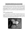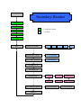
1
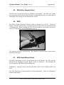
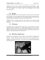
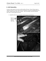
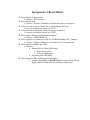
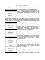
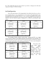
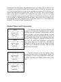
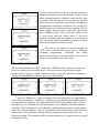
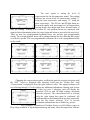
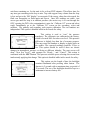
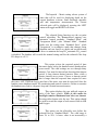
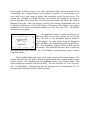
O2ptima Closed Circuit Rebreather Manual O2ptima Manual –User Guide – Rev 1.2 Page 2 of 26 __________________________________________________________________ CONFIDENTIAL This document is for use by, O2PTIMA owners only, and is the property of Lamartek, Inc. dba Dive Rite Dissemination of the information contained herein to outside parties is expressly prohibited. Text, photographs, and figures copyright ©2005 by Asseer & Associates Inc. HammerHead Manual is copyright Joseph A Radomski used under permission. 175 NW Washington St. Lake City, Florida, 32055 United States Phone (386) 752-1087 Fax (386) 755-0613 ALL RIGHTS RESERVED No part of this book may be reproduced or transmitted in any form or by any means, electronic or mechanical, including photocopying, recording or by any information storage retrieval system, without permission in writing from an authorized representative of Asseer & Associates Inc. Warning: The O2PTIMA is a fully closed-circuit diving apparatus which functions in a manner distinctly different from traditional open-circuit scuba. Do not attempt to use the O2PTIMA without proper professional instruction from an authorized O2PTIMA Instructor and without a thorough and complete working knowledge of the material contained in this manual. Careless use of the O2PTIMA can lead to hypoxic blackout in any environment without any prior warning symptoms. Careless use of the O2PTIMA at depths underwater greater than 20 fsw (feet of seawater) can lead to an oxygen convulsion without any prior warning symptoms. Both conditions can cause serious injury or death to the user. The O2PTIMA is equipped with redundant displays and control systems, which will allow a properly trained user to avoid these situations. It is the user’s responsibility to attentively monitor these systems when using the O2PTIMA and to have a working knowledge of the recovery procedures should a problem arise. Proprietary Information - Not to be released without written authorization Asseer & Associates, 5609 Power Road, Ottawa, Ontario, K1G 3N4 O2ptima Manual –User Guide – Rev 1.2 Page 3 of 26 __________________________________________________________________ Table of Contents 1. Preface ....................................................................................... 4 2. User Guide................................................................................. 6 2.1. 2.2. 2.3. 2.4. 2.5. 2.6. 2.7. 2.8. Breathing Loop Assembly ..................................................................................... 6 Canister .................................................................................................................. 7 Inhalation Side ..................................................................................................... 11 Exhalation Side .................................................................................................... 13 DSV (Diver Supply Valve).................................................................................. 14 DIVA.................................................................................................................... 14 ADV (Auto-Diluent Valve) ................................................................................. 14 Electronics............................................................................................................ 15 3. Maintenance ............................................................................ 16 3.1. 3.2. 3.3. 3.4. 3.5. 3.6. 3.7. 3.8. 3.9. 3.10. 3.11. Cleaning / Disinfecting ........................................................................................ 16 Storage ................................................................................................................. 17 O2 Sensors ........................................................................................................... 17 DSV (Diver Supply Valve).................................................................................. 17 O-Rings ................................................................................................................ 18 Batteries ............................................................................................................... 18 Wiring Harness .................................................................................................... 18 Solenoid Valve..................................................................................................... 19 ADV (Auto-Diluent Valve) ................................................................................. 19 Scrubber medium ............................................................................................. 20 Electronics........................................................................................................ 20 4. Troubleshooting ...................................................................... 26 5. HammerHead Instruction Manual Proprietary Information - Not to be released without written authorization Asseer & Associates, 5609 Power Road, Ottawa, Ontario, K1G 3N4 O2ptima Manual –User Guide – Rev 1.2 Page 4 of 26 __________________________________________________________________ 1. Preface Congratulations on your decision to purchase what is quite possibly the most sophisticated self-contained underwater breathing apparatus ever developed. Two years of intensive research, experimentation, and testing by a team of dedicated individuals have culminated in the creation of O2PTIMA, a electronically controlled, mixed-gas, closed-circuit rebreather system. Detailed feedback from experienced and talented divers around the world, as well as extensive unmanned testing, has led to the refinement of an assortment of features that make the O2PTIMA stand out among the rest. Perhaps what most distinguishes the O2PTIMA from other closed-circuit rebreathers is the extent to which the diver has full control over the function of the system. A menu-driven computer control system allows the user to change a wide variety of system parameters, from oxygen partial pressure set point, to diluent gas composition, to display screen lighting, all in “real time” during the course of a dive. The position of the counter lungs can be adjusted to match the particular build of the diver, and the gas supply options are virtually limitless. Or, the most distinguishing aspect of the O2PTIMA may be its system reliability. Computers with independent power-supplies reduce the probability of a system-level electronics failure to almost nil. Reinforced counter lung shells, robust loop fitting connectors, and “durable” breathing hoses mean that mechanical loop failure is extremely unlikely. Then again, the most distinguishing aspect of the O2PTIMA may be the features which alert the diver to a potential problem, and allow the diver to correct such problems before they become serious. A heads-up display and the patented vibrating alarms immediately notify the diver if a critical variable has drifted out of range. The heads up display also acts as a “buddy light” providing a diving companion with information on the oxygen level in the breathing loop at a glance. In just a few seconds at any time during a dive, a diver can simultaneously expose all three oxygen sensors to a known gas composition and ascertain whether the sensors are providing correct readings. Regardless of what particular feature or set of features most distinguish it from all other rebreather systems; the bottom line is that the O2PTIMA is equipped with many important “tools” which can increase the diver’s comfort and ability during a wide range of diving activities. The purpose of this manual, however, is not to glorify the O2PTIMA (you already know how well designed it is, or you wouldn’t be reading this now). Rather, its purpose is to describe in detail the design and function of this sophisticated piece of diving equipment. While all of the “tools” provided by the system greatly enhance the quality and control of a dive, they do require a substantial amount of time to learn. Within your first hour of underwater time on your O2PTIMA rebreather, you will almost certainly start to feel extremely comfortable and confident with the system. Do not allow yourself to become complacent! The irony of an extremely reliable closed-circuit rebreather is that it encourages a diver to become complacent about basic system monitoring. When it comes to rebreather diving, complacency kills! Proprietary Information - Not to be released without written authorization Asseer & Associates, 5609 Power Road, Ottawa, Ontario, K1G 3N4 O2ptima Manual –User Guide – Rev 1.2 Page 5 of 26 __________________________________________________________________ Please take the time to fully understand all of the O2PTIMA’s system components before entrusting your life to them. This manual explains the O2PTIMA in great detail, but only you, the user, can control the outcome of your dives. Learn what the O2PTIMA can do to expand your capabilities underwater. Practice standard operational protocols until they become intuitive. Practice bailout procedures until they become reflexive. And above all, be a responsible diver. Proprietary Information - Not to be released without written authorization Asseer & Associates, 5609 Power Road, Ottawa, Ontario, K1G 3N4 O2ptima Manual –User Guide – Rev 1.2 Page 6 of 26 __________________________________________________________________ 2. User Guide The O2ptima CCR was designed to ensure assembly and disassembly of the unit is straightforward and simple. WARNING: THE FOLLOWING INSTRUCTIONS ARE ASSEMBLY INSTRUCTIONS ONLY. FURTHER TRAINING IS REQUIRED PRIOR TO USING THE UNIT. INITIAL ASSEMBLY IS TO BE COMPLETED UNDER THE SUPERVISION OF THE CERTIFYING O2PTIMA INSTRUCTOR. 2.1. Breathing Loop Assembly The breathing loop can be divided into four separate items (inhalation side, exhalation side, canister, and mouthpiece/DSV). When assembling the breathing loop ensure that all hose fittings have been lubed with oxygen compatible lubricants in order to protect the o-rings. All connectors should only be finger tight. Over tightening can result in damage to the threads and o-rings. All the inhalation connectors are color coded and thread matched to ensure that the components are assembled in the appropriate location with respect to the exhalation side. Proprietary Information - Not to be released without written authorization Asseer & Associates, 5609 Power Road, Ottawa, Ontario, K1G 3N4 O2ptima Manual –User Guide – Rev 1.2 Page 7 of 26 __________________________________________________________________ 2.2. Canister Canister assembly should be performed in a clean dry and well lit area. The canister consists of the following parts; • Head • Input cap • Center body • Extendair Cartridge (scrubber medium) • O2 cells (3) • Wiring Harness • Input and output fittings • O2 Premix entrainment system (including locking thumb nut) Prior to assembly of the canister components, ensure all the parts are clean. Lube should be applied to all o-rings except the scrubber cartridge o-ring (see picture). Proprietary Information - Not to be released without written authorization Asseer & Associates, 5609 Power Road, Ottawa, Ontario, K1G 3N4 O2ptima Manual –User Guide – Rev 1.2 Page 8 of 26 __________________________________________________________________ Scrubber cartridge o-ring 1. Screw in the three O2 cells into the Sensor Holder Disk. No cell should be placed in location 4 unless a stand alone computer is using this as an input. Remove the oring from the O2 cells if applicable. Sensor Holder Disk 2. Snap in the Molex connectors on the rear of the cells ensuring that the color of the wires match the color code on the connection block inside the head (ie. cell #1 is plugged into location 1 on the banana block and so on). This will make cell identification easier when verifying cell life or troubleshooting. Proprietary Information - Not to be released without written authorization Asseer & Associates, 5609 Power Road, Ottawa, Ontario, K1G 3N4 O2ptima Manual –User Guide – Rev 1.2 Page 9 of 26 __________________________________________________________________ 3. Plug-in the wiring harness into the banana jack block inside the head. Ensure that the colors match and that the ground for each cell is plugged into its appropriate spot. Banana Jack Plugs 4. Secure the O2 disk into the head with provided screw. Do not over tighten. Disk Securing Screw Proprietary Information - Not to be released without written authorization Asseer & Associates, 5609 Power Road, Ottawa, Ontario, K1G 3N4 O2ptima Manual –User Guide – Rev 1.2 Page 10 of 26 __________________________________________________________________ 5. Remove the Extendair cartridge from packaging. 6. Remove the red cap from the Extendair cartridge. 7. Feed the O2 Premix rod through the center of the cartridge and secure with the thumb nut on the far side. Thumb Nut O2 Premix rod 8. You will have to hold the rod to prevent from spinning freely while securing the thumb nut. Use fingers on the rod at the start and use a precision screwdriver or allen key to provide leverage when tightning. IMPORTANT: THE THUMB NUT AND THE BASE OF THE O2 PREMIX ROD MUST BE TIGHLY SECURED AGAINST BOTH EDGES OF THE SCRUBBER CARTRIDGE IN ORDER TO AVOID CO2 CHANNELING 9. Sit the canister down on the head and slide the canister body over the unit making sure the proper grooves fit in the head. Secure the canister body by turning the body until locked. 10. Ensure the water trap in the input cap is properly locked down. Secure the input head to the canister body. Proprietary Information - Not to be released without written authorization Asseer & Associates, 5609 Power Road, Ottawa, Ontario, K1G 3N4 O2ptima Manual –User Guide – Rev 1.2 Page 11 of 26 __________________________________________________________________ 11. Insert hose connectors into the head and input cap. The red connector must be screwed into the head (left hand thread). The black connector is screwed into the input cap. 2.3. Inhalation Side The inhalation side comes over the divers left shoulder. It is comprised of 2 hoses (with red connectors), 1 Auto-Diluent valve and 1 counter lung with appropriate fittings. All the inhalation side threads are left handed threads and red in color. 1. Attach ADV to the inhalation lung. There is no specific direction for the ADV orientation but you will need to ensure that the diluent attachment hose can reach the connector and that you can easily reach the manual shut-off while wearing the unit in case of emergency. Proprietary Information - Not to be released without written authorization Asseer & Associates, 5609 Power Road, Ottawa, Ontario, K1G 3N4 O2ptima Manual –User Guide – Rev 1.2 Page 12 of 26 __________________________________________________________________ 2. Attach the short breathing hose with red connectors to the ADV and the other end to the assembled canister. This hose has left handed threads and does not have a specific flow direction. 3. Attach the diluent supply to the ADV. This connection should only be finger tight. Ensure that the manual shut-off is accessible when wearing the unit. 4. Attach the red connector from the long breathing hose to the front of the ADV. IMPORTANT: The DSV has 2 directional mushroom valves. It is critical that the mushroom valves are in the proper orientation. A mushroom valve check should be performed prior to connecting either end of the DSV hoses to the T-Piece or ADV. Proprietary Information - Not to be released without written authorization Asseer & Associates, 5609 Power Road, Ottawa, Ontario, K1G 3N4 O2ptima Manual –User Guide – Rev 1.2 Page 13 of 26 __________________________________________________________________ 2.4. Exhalation Side The exhalation side comes over the divers’ right shoulder. It is comprised of 2 hoses (black connectors), 1 T-Piece and 1 counter lung with appropriate fittings. All the exhalation side threads are right handed threads and are black in color. 1. Attach the T-Piece to the exhalation lung. The T-Piece does not have a specific orientation. 2. Attach the short breathing hose to the T-Piece and to the input side of the assembled canister (see canister assembly instructions). This hose does not have a specific flow direction. 3. Attach the long breathing hose to the front of the T-Piece. Proprietary Information - Not to be released without written authorization Asseer & Associates, 5609 Power Road, Ottawa, Ontario, K1G 3N4 O2ptima Manual –User Guide – Rev 1.2 Page 14 of 26 __________________________________________________________________ 2.5. DSV (Diver Supply Valve) The DSV does not typically need any assembly or disassembly. The DSV does contain two mushroom valves to provide flow direction. Both mushroom valves are removable for maintenance and cleaning (see the Maintenance section). 2.6. DIVA The DIVA (Display Integrated Vibration Alarm) is designed as a H.U.D. – Heads Up Display. This unit assists the diver in monitoring PPO2 levels with color coded LED’s and a vibrating alarm. When installing the DIVA on the mouthpiece, ensure that a diver has a clear view with the DSV in his mouth and his mask on. The connector end screws on to the head. The connector is keyed in order to ensure proper orientation of the pins. 2.7. ADV (Auto-Diluent Valve) The ADV (Auto-Diluent Valve) is located on the divers left shoulder. The ADV provides diluent into the breathing loop upon descent as the air compresses. This eliminates the need to manually add diluent to the breathing loop. WARNING! ALWAYS HAVE AN INLINE SHUT OFF VALVE WHEN USING AN ADV. The ADV should only be disassembled for routine maintenance. Please see maintenance section of the manual. Proprietary Information - Not to be released without written authorization Asseer & Associates, 5609 Power Road, Ottawa, Ontario, K1G 3N4 O2ptima Manual –User Guide – Rev 1.2 Page 15 of 26 __________________________________________________________________ 2.8. Electronics The O2ptima electronics are supplied by Juergensen Marine. Please see the HammerHead manual for specific user functionality. The O2ptima electronics are shipped out of the facility with all lock out codes erased from the handset. This renders the electronics inoperable until the proper code is keyed into each of the handsets. Once the code has been entered, it will remain unlocked unless the codes are deliberately erased. Each unit has a specific code therefore the code for one unit will not work on another unit. In order to receive the code for your O2ptima unit you must complete the following; • Successfully pass an approved diver level CCR O2ptima course • All waivers and liability forms have been signed and the originals have been received by the manufacturer (Asseer & Associates Inc.). In order to receive training on your unit the lock out code will be sent to the instructor of your choice. Upon successful completion of the course the instructor will hand over the lock out code for your unit. The O2ptima electronics also have a Trimix capability. The Trimix functionality is also locked out by a secondary lock out code. In order to unlock the Trimix functionality you must successfully complete an approved Trimix diver level CCR course. The unit can be “re-locked” at any time by clearing the codes. Each handset is powered by a stand alone battery. The recommended battery for the O2Ptima is the Saft LS14500. The (+) plus side of the battery should be at the bottom of the battery compartment while the (-) negative side of the battery should be against the spring. Tighten the battery cap using a coin. The O2ptima electronics have also been programmed to remain on the start-up screen if the power is ever reset at the surface or during a dive. This will only happen on the primary if the battery no longer has enough power to fire the solenoid valve and if the is not enough power in the secondary to provide alarms. WARNING!!! IF THE START SCREEN APPEARS ON EITHER OF YOUR HANDSETS DURING A DIVE, ALL TISSUE INFORMATION HAS BEEN RESET. DO NOT USE THIS HANDSET FOR DECOMPRESSION INFORMATION. 2.9. First Stage Regulators The O2ptima has two first stage regulators, one for diluent and one for oxygen. The IP (intermediate pressure) for the diluent regulator is to be set to factory standards (135 psi). The oxygen first stage IP must be set to 110 psi in order for the solenoid valve to function properly. This should be verified during unit assembly and corrected immediately if any discrepancy is noted. Proprietary Information - Not to be released without written authorization Asseer & Associates, 5609 Power Road, Ottawa, Ontario, K1G 3N4 O2ptima Manual –User Guide – Rev 1.2 Page 16 of 26 __________________________________________________________________ 3. Maintenance To ensure many years of trouble free diving, it is critical that proper maintenance be performed on the O2ptima. Lack of maintenance can affect the proper functionality of the unit and will void any warranty. 3.1. Cleaning / Disinfecting All components which come into contact with the divers breathing loop must be routinely cleaned and disinfected (recommend Virkon be used as cleaning agent). Ensure that the disinfectant is rinsed out of the loop prior to using it. Improper cleaning can result in growth of mould which can affect the proper operation of certain components. • Remove front section of the breathing hose and clean with disinfectant. Hang this section vertically with the inhalation side at the top so that any residual disinfectant will drain through the one way mushroom valves. • Disconnect the hose from the canister. Partially fill the lungs with disinfectant and swish around. Drain the disinfectant through the lower purge valve or T-Piece and hang to dry. • Clean rear breathing hoses by spraying disinfectant through the hose and hang to dry. • Disassemble the canister. Remove the water trap on the input head. Spray disinfectant and wipe dry with clean cloth. • • Remove canister center body. Spray disinfectant and wipe dry with clean cloth. Clean the top of the O2 sensor disk by spraying a cloth and wiping clean the upper surface. Do not spray the top of the O2 sensors directly. Note: The bottom of the head should be cleaned every 6-10 hours of diving or anytime flooding has occurred and residue is seen during inspection. To clean bottom of the head, Proprietary Information - Not to be released without written authorization Asseer & Associates, 5609 Power Road, Ottawa, Ontario, K1G 3N4 O2ptima Manual –User Guide – Rev 1.2 Page 17 of 26 __________________________________________________________________ completely remove O2 cells and disk by disconnecting the wiring harness. Spray disinfectant on a cloth and clean the bottom of the head. WARNING: YOU WILL NEED TO RE-CALIBRATE O2 CELLS ONCE THE HARNESS HAS BEEN DISCONNECTED. 3.2. Storage If storing the O2ptima CCR for any extended period of time, store the unit in a clean and dry environment. All hose connections containing o-rings should be disassembled and the canister should be in a disassembled state. The batteries should be removed from the electronic handsets and the battery caps should remain off the handsets. IMPORTANT: Once activated, oxygen cells will continue to react with the ambient atmosphere. When re-assembling your unit, verify that all the cells are still functioning within spec. 3.3. O2 Sensors The O2ptima CCR uses Teledyne R22D oxygen sensors. Sensors should be replaced as degradation of the cell takes place. If a cell has degraded past safe levels, it will not register the minimum amount of voltage and therefore the electronics will not be able to calibrate for this cell. This can also be seen when using the MV Display function on the handsets (see HammerHead manual for further detail). 3.4. DSV (Diver Supply Valve) The DSV has two mushroom valves in order to control direction of inhalation and exhalation. Regular maintenance includes inspection of the valves and replacement if necessary. In order to inspect the valves loosen the hose clamps attaching the front breathing hoses and remove the hoses. You can now access and remove the mushroom valves from each side. Proprietary Information - Not to be released without written authorization Asseer & Associates, 5609 Power Road, Ottawa, Ontario, K1G 3N4 O2ptima Manual –User Guide – Rev 1.2 Page 18 of 26 __________________________________________________________________ IMPORTANT!!! When re-assembling the DSV, extreme care should be taken to ensure the valves have been put in the proper orientation for air loop flow. The long hose with red connector should be on the inhalation side and the long hose with black connector should be on the exhalation side. A mushroom valve check should perform after reassembly. 3.5. O-Rings The O2ptima CCR has multiple o-rings contained within the breathing loop. All o-rings should be changed on a yearly basis or sooner if degradation is seen. The canister has nine (9) o-rings and the breathing loop has sixteen (16) o-rings that need to be periodically inspected and replaced each year. The reason for such a high o-ring count in the O2ptima CCR is that the majority of fittings have double o-ring fittings. 3.6. Batteries The recommended battery for the O2ptima CCR electronics is the 3.6 Volt Saft Lithium Ion (Saft P/N: LS14500-10). Many factors affect battery life such as the frequency of the solenoid firing and back lighting for the electronics. It is recommended that the battery be replaced every 6 hours of diving but careful attention should be used if dive profiles require a high frequency of solenoid firing or long duration of back lighting. If the unit is not going to be used for an extended period of time (more than 24 hours), it is recommended to remove the batteries to conserve power. WARNING! WHEN THE BATTERIES ARE REMOVED FROM THE HANDSETS, ALL TISSUE INFORMATION IS LOST. A SURFACE INTERVAL OF 24 HRS IS REQUIRED PRIOR TO USING THE HAMMERHEAD ELECTRONICS TO PROVIDE DECOMPRESSION INFORMATION. Additional information on batteries can be found in the HammerHead manual. 3.7. Wiring Harness The wiring harness relays the electrical signal from each of the cells to the main connection block inside the head. It is critical that a good electrical contact is made between the connection block and the head. Improper connection can lead to erroneous oxygen levels or the inability to calibrate a specific cell. The banana jack connectors and receptacles should be cleaned every 20 hours of use or any time excessive moisture or flooding has occurred. The wiring harness should be replaced Proprietary Information - Not to be released without written authorization Asseer & Associates, 5609 Power Road, Ottawa, Ontario, K1G 3N4 O2ptima Manual –User Guide – Rev 1.2 Page 19 of 26 __________________________________________________________________ every 12 months or at any time excessive corrosion is seen on either end of the wiring harness connectors. 3.8. Solenoid Valve The solenoid valve selected for the O2ptima CCR should provide years of trouble free diving. That said, like any other mechanical components with moving parts, the solenoid valve will degrade with time and is severely impacted if subjected to any internal moisture or condensation. The O2ptima CCR has been designed is such a way that the user can easily replace the solenoid valve. 3.9. ADV (Auto-Diluent Valve) The ADV provides breathing loop gas upon demand by integrating a second stage regulator into the loop. The ADV should be opened after every 10 hours of diving to rinse out any residue accumulating on the diaphragm and internal components. The lever mechanism and pivot should be serviced on a yearly basis. Adjustment for the ADV can be found at the end of the pivot lever mechanism. When assembling/disassembling the ADV ensure that the inner rod is held stable by hand or tool to prevent damaging the inner key way. IMPORTANT! ALWAYS HAVE AN INLINE SHUT OFF VALVE WHEN USING THE ADV Proprietary Information - Not to be released without written authorization Asseer & Associates, 5609 Power Road, Ottawa, Ontario, K1G 3N4 O2ptima Manual –User Guide – Rev 1.2 Page 20 of 26 __________________________________________________________________ 3.10. Scrubber Medium The O2ptima CCR has been designed to use Extendair cartridges manufactured by Micropore. The Extendair absorbent use the same chemistry as granular absorbents but they are formed into sheets that are rolled into easy to use cartridges. The Extendair cartridge has been extensively tested in order to determine maximum duration of the scrubber material. For dives within recreational dive limits (< 130ft, nodecompression) the Extendair cartridge can be used for a period of up to two (2) hours in cold water (50 F) and three (3) hours in warm water (70 F). WARNING!!! REPLACE SCRUBBER CARTRIDGE EVERY THREE (3) HOURS WHEN DIVING WITHIN RECREATIONAL LIMITS IN WARM WATER. WARNING!!! REPLACE SCRUBBER CARTRIDGE EVERY TWO (2) HOURS WHEN DIVING WITHIN RECREATIONAL LIMITS IN COLD WATER. WARNING!!! REPLACE SCRUBBER CARTRIDGE IF LEFT IDLE IN THE UNIT FOR A PERIOD OF MORE THAN TWENTY FOUR (24) HOURS. WARNING!!! REPLACE SCRUBBER EVERY THREE (3) DIVES EVEN IF SCRUBBER DURATION IS NOT FULLY USED. WARNING!!! FOR DIVES PAST RECREATIONAL DIVE LIMITS, CONSULT TEST DATA RESULTS FOR SCRUBBER DURATION. RESULTS CAN BE FOUND ON MICROPORE WEBSITE (www.extendair.com). 3.11. Electronics The electronics must be rinsed in fresh water after every use. The battery cap is used to transmit the power signal from the battery to the electronics therefore it is critical that the battery cap threads and battery spring be cleaned regularly. Any accumulation of deposits will affect battery consumption. The o-rings on the handsets should be inspected regularly and replaced every twelve (12) months. Proprietary Information - Not to be released without written authorization Asseer & Associates, 5609 Power Road, Ottawa, Ontario, K1G 3N4 O2ptima Manual –User Guide – Rev 1.2 Page 21 of 26 __________________________________________________________________ 4. Unit Assembly Section 4 of the manual covers the overall assembly of the unit. Some of these steps are required to be done every dive while others are only done when first assembling the unit or when a complete down of the unit is required. The first assembly of the unit should be done with a certified Optima instructor. 1. Assemble back soft cover and plastic shell using provided hardware. Bolts for plastic shell and soft back only Proprietary Information - Not to be released without written authorization Asseer & Associates, 5609 Power Road, Ottawa, Ontario, K1G 3N4 O2ptima Manual –User Guide – Rev 1.2 Page 22 of 26 __________________________________________________________________ 2. Run the required hoses through the provided ports (see previous picture for front view). 3. Secure wing and Transpac or Tranplate to internal support bar using provide hardware. Bolts are to secure to the threaded holes on the support bar. Feed ports for diluent and O2 hoses Internal Support Bar Threaded holes on the internal support bar to secure wing and harness 4. Insert diluent and O2 bottle. Secure bottles using Velcro straps and hose tie down strap. Screw in first stage regulators and ensure that the valve tab can properly fit with bottom base. Velcro straps Hose tie down strap Proprietary Information - Not to be released without written authorization Asseer & Associates, 5609 Power Road, Ottawa, Ontario, K1G 3N4 O2ptima Manual –User Guide – Rev 1.2 Page 23 of 26 __________________________________________________________________ Valve tabs 5. Insert canister and screw on the O2 inject hose. The O2 hose should only be finger tight. DO NOT OVERTIGHTEN O2 HOSE. Canister tie down strap O2 injection hose connection (hand tight only). Proprietary Information - Not to be released without written authorization Asseer & Associates, 5609 Power Road, Ottawa, Ontario, K1G 3N4 O2ptima Manual –User Guide – Rev 1.2 Page 24 of 26 __________________________________________________________________ 6. Install back lid 7. Install Breathing lungs. The upper harness has to loop under the lungs. Clip the top of the lungs with the provided clips. Upper lung clips Loops for manual addition hoses Proprietary Information - Not to be released without written authorization Asseer & Associates, 5609 Power Road, Ottawa, Ontario, K1G 3N4 O2ptima Manual –User Guide – Rev 1.2 Page 25 of 26 __________________________________________________________________ 8. Install remainder of the breathing loop as per directions from Section 2. Proprietary Information - Not to be released without written authorization Asseer & Associates, 5609 Power Road, Ottawa, Ontario, K1G 3N4 O2ptima Manual –User Guide – Rev 1.2 Page 26 of 26 __________________________________________________________________ Troubleshooting Issue / Problem Positive and/or negative pressure tests can not be preformed • • • • Oxygen cell calibration • • • Handsets are in dive mode at the surface • • Handsets reset to start up screen • • • Solution Ensure all fittings are secured. Ensure DSV is fully closed. Ensure over pressurization valve is fully closed. Spray all connections with soap and water mixture. Fill breathing loop and inspect for small bubbles. Tighten any loose connections. Ensure the loop is flooded with 100% O2. Verify that each cell is producing over 40 mV. Verify wiring harness and clean all connections on the harness and connection block. Verify that the proper sea level has been set on the unit. Verify that the pressure transducer is clear of any dirt or accumulated salt deposit due to improper rinsing. Change batteries. Verify cap and spring for any accumulated residue. Verify the bottom of the battery compartment for any accumulated residue. Proprietary Information - Not to be released without written authorization Asseer & Associates, 5609 Power Road, Ottawa, Ontario, K1G 3N4 Optima HammerHead Electronics Instruction Manual The Hammerhead, also has handsets called the primary and secondary, but each has different purpose and functions. The primary is responsible for maintaining the selected set-point, displaying the measured PO2 for the three main oxygen sensors, time, depth and decompression information. The secondary is a backup display for the main oxygen sensors, and controller for the DIVA Heads-Up display. The secondary DOES NOT CONTROL the solenoid, it is meant to allow the diver to manually maintain the breathing loop in the event of a primary failure. The only common point between the primary and secondary is the oxygen sensors. Each controller has an independent power source. SETUP and INSTALLATION The Hammerhead allows for the tracking of sensor health by allowing the user to display millivolt readings for each sensor. This is accomplished by utilizing the “MV DISPLAY” option located under the “OPT” menu on both the primary and secondary handsets once the harness is connected. Recording the millivolt readings for each cell when exposed to air and oxygen will expose cells that are going non-linear. The actual oxygen percentage used in calibration should also be recorded. Normal display Primary Handset Set-Point #1 Set-Point #2 Changed Version 4.5 Version 4.5 or Greater Set-Point #3 User Defined Values Set-Point #4 User Entry Updated / User GF Factors Set-Point #5 GAS 1 2 3 4 5 6 7 8 9 10 FO2 OC CLOSED CIRCUIT OPT DEFINE GAS CONSERVATISM OPEN CIRCUIT 1 2 3 4 5 10 9 8 7 6 1 2 7 CUSTOM GRADIENT DEFINE SET POINT 3 8 9 GF-HI 1 4 5 6 10 11 GF LOW 2 3 4 5 CALIBRATE O2 SET SEA LEVEL BACKLIGHT TIMER 2 – 30 Seconds IMPERIAL--METRIC IMPERIAL METRIC SOLENOID FIRING JUERGENSEN STANDARD AUTO SHUTDN RATE 2 to 30 minutes MV DISPLAY STANDARD ERROR 1% to 10% DIAGNOSTICS Erase Flash Test Flash Cycle Outputs Test Watchdog ABOUT Enter SN Volts Display Initialize Calibrate PSI Normal display Secondary Handset Set-Point #1 Set-Point #2 User Defined Values Set-Point #3 User Entry Set-Point #4 Set-Point #5 OPT DEFINE SET POINT 1 2 3 BACKLIGHT TIMER 2 – 30 Seconds AUTO SHUTDN RATE 2 to 30 minutes 4 5 CALIBRATE O2 MV DISPLAY DIAGNOSTICS SET DISPLAY MODE ABOUT Erase Flash Test Flash Test Watchdog Enter SN Initialize Volts Display USER SETPOINT 1.0 PPO2 MODE System Overview Before being able to dive the unit, it is necessary to understand a few basic conventions used by the controllers, calibrate the oxygen sensors and set diver preferences. Initially out of the factory, some common set-points are defined, all gas mixes are programmed to AIR, and sea level is set at approximately 1840 ft above sea level. If the data becomes corrupted or unusable, it can be easily reset to factory defaults. The primary handset can operate using Imperial or Metric units of depth. The PO2 on both handsets is displayed in units of ATA not Bar, which is used by the Inspiration and several dive computers. This variation is minimal, and conforms to NOAA exposure definitions. The European tradition of using NOAA exposure tables but treating the values, in units of Bar is slightly more conservative for oxygen exposures. Planning the dive with the set-point in Bar while set-point is actually in ATA will result in a slightly more conservative profile. The Hammerhead electronics are unique in several ways, the key areas being setpoint switching and set-point maintenance. There are electronics that are fully automatic, mixed, and manual only, the hammerhead offers all of these options to the diver. Closed circuit rebreather divers typically use more than a one set-point during a dive. Manufacturers have combated this in various ways, some have taking the standpoint that the user is not capable of switching set-points and the electronics must do it. This typically involves setting up two predetermined points and when a manufacturer chosen dive depth is reached the controller automatically adopts the appropriate set-point. Other manufacturers have taken the stance that the diver should have full control of the setpoint switching such as the Inspiration. This puts full responsibility for all set-point switches squarely on the diver. Lastly, there are fully manual rebreathers that do no set-point holding at all, the loop composition is fully the responsibility of the diver. The first case is probably best for the new CCR diver, while manual set-point switches are probably the mode of choice for the experienced diver. Fully manual rebreathers are not recommended. The Hammerhead supports all modes. The manual mode is designed for emergency use only. The two set-point switching modes are supported based on the starting set-point. If the diver selects a set-point that can’t be supported on the surface, the electronics will start the dive with a set-point of 0.4 ATA, transition to 1.0 ATA at 1m, and finally the chosen set-point at 3m. The other unique feature pertaining to set-point maintenance is the algorithm used to hold the selected set-point. Each manufacture comes up with their own unique formula to determine when oxygen is injected; the user generally has no control over this function. The Hammerhead has two user selectable modes, standard mode, which allows a user defined deviation below set-point before the solenoid will fire, or Juergensen mode which adapts to depth and distance from set-point to determine firing duration and frequency. Each handset has two buttons, which are used for programming and control. Pressing either button will activate the backlight for the user chosen time, and will wake up a handset that is in sleep mode. The left button scrolls through menu selections and values while the right button selects the current value. The handsets will timeout after a 10 second period of inactivity, and return to the normal operation mode. Several options will require confirmation. Failure to confirm action cancels any changes. The handset Backlight and LEDs also serve as a CRITICAL ALARM. This alarm is disabled on the primary while operating in open circuit mode The design goal of the HammerHead electronics was to make the safest CCR controller in the industry. All reasonable attempts have been made to prevent a single failure from becoming a life-threatening occurrence. When the electronics were being designed, Kevin Juergensen sketched out what he called a “Threat Matrix”, listing possible conditions along with generated warnings and solutions. Juergensen’s Threat Matrix Diver forgets to turn on unit: ¾ Answer: Wet Switches Wet Switches Fail: ¾ Answer: Pressure Transducer will activate unit at 1m pressure Diver sets unit to Open Circuit, but is still breathing the loop. ¾ Answer: Solenoid Override at 0.19 PO2 Diver sets unit to Manual Control, but forgets to add O2: ¾ Answer: Solenoid Override at 0.19 PO2 Diver ignores Primary and Secondary Display: ¾ Answer: Add HUD/DIVA Diver ignores or is unaware of DIVA LED Red Warning of PO2 Danger: ¾ Answer: Trigger Vibrator at 1.8 and above, or 0.19 and below. Diver ignores Vibrator and LED: ¾ Answer: Primary Red or Green LED firing • Red for Low ppO2 • Green for High ppO2 Secondary Red LED firing Diver ignores LED's in Primary and Secondary: Answer: Backlights in BOTH handsets begin to flash. This is highly visible to both the diver, and any nearby divers. ALARMS START Primary READ PO2 Green Flashing LED FLASHING BACKLIGHT Red Flashing LED PO2 >= 1.8 AVERAGE PO2 PO2 <=.19 FLASHING BACKLIGHT FIRE SOLENOID SYSTEM OK START Secondary READ PO2 <PO2! ERROR!> DIVA VIBRATING FLASHING BACKLIGHT <PO2! ERROR!> DIVA VIBRATING FLASHING BACKLIGHT PO2 >= 1.8 Check Status PO2 <=.19 RED LED on Secondary 25% and Up DIVA Red LED Every 2 seconds ALERT < 15% 15% to 24% or Sensor Voted Out DIVA Green LED Every 8 seconds <OK> DIVA Orange LED every 5 seconds <WARN> RED LED on Secondary Handset Display Details The Primary handset has several informational screens that vary depending on whether the unit is in surface mode, no deco obligation, or deco required conditions. This is the surface mode screen; the top line consists of the surface interval, selected set-point or open circuit indicator, maximum depth of previous dive, and 1:38 OC 008 000 finally dive time. The second line is the current PO2 0.73 0.73 0.71 reading for the three oxygen sensors. These sensors respond in real time and are not buffered or averaged over some arbitrary sample time. This allows the diver to accurately judge the response time of the sensors and see how the gas is mixing within the head. The diver should not be concerned over a short spike in readings. The two outer sensors, one and four, are positioned closest to the solenoid and will exhibit the highest spiking. The next display is the first of three screens presented while in dive mode. The first line displays current depth, selected set-point, dive time and 031 1.0 0:00 031 1.11 1.11 1.10 maximum depth. The second line displays the PO2 readings of the three sensors. If any sensor reading is followed by a “*” that sensor has been voted out and is not used in the average PO2 calculation. 033 21% 0.7 0:00 034 NO STOP The next screen depends on the status of the diver’s decompression obligation. The top line is the same as on the previous screen with the change being on the second line. Instead of the PO2 being displayed, the oxygen percentage of the selected diluent and “No Stop” is displayed until the diver enters a required decompression stop. 170 1.0 0:12 172 21% 2@ 20 12 The first line is the same as the previous two screens, while the second line displays the oxygen percentage of the diluent, deepest stop depth and stop time followed by the total ascent time. The sample screen shows the deepest stop at 20fsw for two minutes and a TTS of 12 minutes. 032 Air The final screen may seem an annoyance, but it serves as a reminder to the diver. The name of the diluent the diver has selected and the programmed oxygen percentage of the diluent.are displayed on the second 0.7 0:00 034 21% line. This should help insure the diver doesn’t try and use a nitrogen mix with same oxygen percentage as a helium based gas Set-Point Operation One of the main features of the hammerhead is the ability for the diver to select a new set-point based on a user programmed set of five choices. The hammerhead comes pre-programmed with set-points of 0.4, 0.7, 1.0, 1.2, and 1.4. Regardless of the current operating set-point pressing the left button will cycle through the set-point choices in sequence. Once the desired set-point is displayed it is selected by pressing the right button. 1:38 0.73 0.4 008 000 0.73 0.73 1:38 0.73 0.7 008 000 0.73 0.73 1:38 1.2 008 000 0.73 0.73 0.73 1:38 0.73 1.4 008 000 0.73 0.73 1:38 0.73 1.0 008 000 0.73 0.73 The secondary handset displays system status, warnings and PO2 on a single screen. Any PO2 changes on the primary should be also performed on the secondary. All warnings and alarms are based on the deviation from the selected set-point.The set-point is selected in the same manor as the primary, pressing the left button to cylce through the choices and the right button to select the displayed set-point. <OK> 1.00 1.0 1.00 ALERT 1.0 1.2* 0.86 1.0 1.00 0.7 0.81 <WARN> 0.8 1.1* 0.86 0.7 0.81 PO2! ERROR 0.1* 0.0* 0.0* The top line of the display shows system status (<OK>, <WARN>, ALERT, or PO2! ERROR!). This is followed by the calculated average PO2 , and the selected setpoint. The second line displays the PO2 measurements for each sensor. Any individual sensor out of range will be voted out. The voting logic used in both the primary and secondary handsets is identical. Any sensor that is 15% out of range from the average of the remaining two sensors will be voted out. The second, third and fourth screenshots show sensor one voted out. The second screenshot shows system status of <WARN>, this is indicated if any sensor is voted out or average po2 is at least 15% from selected set-point. The next screen shot shows an error of at least 25%, so ALERT is indicated. The last screen shows a status that no diver wishes to see, PO2 ERROR, this will be indicated if the average PO2 reaches 1.8 or is 0.19 and below, the RED LED and the backlight are illuminated. Handset Options and Programming GAS NEXT SELECT AIR NEXT 21/ 0 SELECT FO2 NEXT SELECT Diluent ppO2 is: 0.22 The additional functions in both the primary and secondary are accessed by scrolling past the set-point selections using the left button. On the primary, the first option available is the gas selection prompt. Pressing the right button will select this function. Each press of the left button scrolls to the next programmed gas mix until all 10 are displayed, eventually returning to first mix. Once the desired mix is displayed, pressing the right button will select it. The diver will then be prompted to confirm or cancel the mix change. Pressing the left button confirms the selection, while the right button cancels the switch The next selection is the FO2 display screen. Pressing the right button will immediately display the calculated PO2 for the current diluent and current depth. A proper loop flush with diluent should result in this value. OC NEXT SELECT OC Open Circuit OPT NEXT SELECT The next option allows the diver to put the handset in either open circuit or close circuit mode. In open circuit mode, solenoid control is disabled, unless the PO2 falls to 0.19Ata. This function serves two purposes. The first allows the diver to bail onto open circuit and still have decompression obligations calculated. The second is to use the handset as a stand-alone dive computer. The left button toggles between modes while the right button selects displayed mode. The system has a short cut out of open circuit and into closed circuit. If the diver chooses a set-point while the handset is in operating in open circuit, the handset immediately switches to closed circuit mode with the selected set-point. The next set of options is entered through the “OPT” menu. Selecting this screen enters a sub-menu containing programming, calibration, and testing options. Some of these selections will be locked out for safety once the handset enters dive mode. The first function under the “OPT” menu is the “DEFINE GAS” option; this allows the diver to program up to ten custom mixes. These gases can be any nitrogen-oxygen, helium-oxygen, oxygen, or trimix. Each gas can have a user-selected name consisting of 6 characters and should be named to allow easy identification.. Define Gas NEXT SELECT Gas Mix 1 NEXT SELECT Air NEXT SELECT Once the “Define Gas” screen is displayed, the diver must press the right button to select. The next prompt is “Gas Mix 1”, continue pressing the left button until the mix to be programmed is displayed. The right button will enter the gas-naming screen. Choose any name up to six characters; the current character will be displayed with the character underlined. The left button will cycle through available characters while the right button proceeds to the next character. After all six characters have been entered; entry of the gas composition will be prompted, starting with the oxygen percentage followed by the helium percentage. The remainder will be assumed nitrogen. For oxygen, enter an oxygen percentage of 99%. The next option is setting the level of conservatism for the decompression model. The original software has eleven levels of conservatism, setting “1” Conservatism being the least conservative and setting “11” being the NEXT SELECT most conservative. The GF-low and GF-high limits are decreased equally with increasing level of conservatism forcing deeper stop depths and lower allowed limits of inert gas loading. Starting with version 4.5, true gradient factors are employed with separate limits determining where the stops begin and when to proceed to the next level. There are now five preprogrammed gradient factor sets and one user programmable setting. The selected gradient factor can be changed during the dive allowing full control over the dive profile. The user programmable selection can even be reprogrammed while in dive mode. GF [1] NEXT [10/100] SELECT GF [2] NEXT [20/ 95] SELECT GF [3] NEXT [25/ 85] SELECT GF [4] NEXT [30/ 75] SELECT GF[5] NEXT [35 70] SELECT GF User NEXT [95/100] SELECT Changing the conservatism requires scrolling the past the set-point selections until the “OPT” screen is displayed then selecting, scroll past the “Define Gas” until “Concervatism” is displayed. Press the right button to select, The original software will now allowing through 11 levels without any additional information. Starting with version 4.5 there are now 6 selections each will display the associted GF-Low and GF-High settings associated with the selection. The conservatism level is selected Confirm with the right button then must be confirmed. All Yes No confirmations on the HammerHead are done purposedly with the left button selecting “Yes” to prevent accidental confirmations due to double key presses. For a complete explanation of Gradient Factors see Erik Bakers paper on Deep Stops available at ftp.decompression.org and many other decompression software sites. Gradient factors is a method used to control the shape of the decompression profile. in a consistent manner. There are two parameters GF-Low and GF-High. The first parameter determines where the initial stop begins. The second parameter determines the maximal allowing tissue loading upon surfacing. These two points determine the slope used to modify the “M-values” during the ascent. For each given depth the “M-value” is lowered based on the computed GF for that depth. For example if the GF settings are 10/95, the diver is allowed to ascend until the tissue loading is 10% of the controlling compartment, at each sucessive stop depth, the maximal tissue loading is increased based on the calculated slope until the GF-High is reached on the last stop. GF-High is the ultimate level of conservatism determing the final surfacing compartment tension. The lower the value is for GF-Low the deeper the first stop will be. The lower the value is for GF-High the longer the overal decompresssion will be. A unique ability of the HammerHead decompression software is allowing the diver to change conservatism levels while underwater. This has some potential benefits as well as potential downsides. If the diver plans on using the ability to change conservatism while underwater , the diver should start with the most conservative setting expected, and lower the level of conservatism, conditions permitting. Higher levels of conservatism and/or lower GF-Low will generall result in deeper initial stops. It is not recommended going from a higher GF-Low value to a lower value while underwater unless you are still below the expected stop depth of the new setting. Changing to a new conservatism level with a lower GF-Low might require the diver to descend to the new required stop depth or stay at current level until offgassing catches up. The alternative is to program a custom conservatism setting with the same GF-Low setting and a new less conservative GF-High setting. The first predefined conservatism setting 10/100 is very aggressive with deep initial stops with a surfacing compartment gradient equal to Buhlman’s limits. This setting is primarily designed for fit individuals in good physical fitness. The second setting 20/95 stages the initial stop shallower but backs off allowable surfacing limits The third setting is applicable to most divers with light workloads and warm water. The fourth setting covers most divers with moderate work loads for a wide variety of water temperatures. The last predefined value is ultra conservative with the lowest allowable tissue tensions. This setting has the shallowest of the initial stops and longest stop times. The final setting defaults to 36/71 which is almost identical to setting 5, and just serves to initialize the variables and should.be redefined to some suitable values. The Hammerhead enforces that the GF-Low setting must be 5% less than the GF-High value. In practice, this limitation should force a stop depth one level deeper than the maximal allowable tissue loading. Creating and using custom gradient factors should only be undertaken by those that understand the consequences of these settings. The limits imposed by the “Custom GF” entry insure that settings should not be less conservative in theory than an unmodified Buhlman profile. Aggressive settings should not be undertaken lightly, the risk of decompression sickness is real. It is not recommended diving any computer to the maximal limits. Conservatism settings 3 and 4 are a good balance of potential risk and decompression obligation. NO conservatism setting or decompression plan can guarantee ZERO risk of decompression sickness! The next option allows the entry of the custom gradient discussed in the previous section. The first value entered is the GF-High, followed by the GF-Low setting. Custom Gradient Gf Hi = [100] Custom Gradient NEXT SELECT Custom Gradient Gf Lo = [ 95] This is necessary to allow setting the upper limit for the GF-Low setting 5% below the GF-High value. This option allows the defining of five set-points. After choosing the “Define Set Point” option, the handset will begin prompting with “Set Point 1” the left button Define Set Point scrolls to the next set-point while the right button enters NEXT SELECT the programming for the displayed set-point. The handset will display the current value. The left button is used to change the value of the chosen set-point. This starts with the current setting, incrementing to a maximum of 1.6 and rolling over back to the low value of 0.4. Once the desired value is displayed, the right button is used to select the setting. Values that are programmed on the primary should also be programmed on the secondary. The diver needs to select the same set-point on both handsets, since alarm generation on the secondary is based on variation from the selected setpoint. Once the calibrate option is selected the next screen will show “Fill Loop w/o2”, with prompts for “Ready “ and “Cancel”. This action is confirmed with Calibrate O2 the LEFT button. This prevents a double press selecting NEXT SELECT this screen from inadvertently applying this change. The calibration technique used with the Hammerhead electronics is the same as most other CCRs and requires a different approach from the original Inspiration electronics. The HammerHead holds a very stable calibration; it is not necessary to constantly recalibrate the handsets. The recommended method is to evacuate all the gas from the loop, flush with oxygen and repeat at least FOUR times. On the final flush, totally fill the loop until the OPV releases. Go to the “MV display” screen and take note of the values, exit this screen to prevent the unit from remaining on. Let the unit sit for at least FIVE minutes. This allows time for any inert gas remaining in the loop to mix. Top with oxygen if any volume from the loop is lost and go to the “MV display” screen again. If the sensor values have decreased, the flush was incomplete so flush again and repeat. Once MV readings are stable, vent excess gas until the loop is at ambient pressure (the easiest way is to vent through the OPV, opening the DSV risks contamination), enter the “Calibrate O2” screen and select ready. Immediately go to the “Calibrate O2” screen on the secondary, select and calibrate. The primary and secondary each require calibration. The two handsets are independent! This option is disabled while in dive mode for safety. This setting is used to “zero” the pressure transducer. The electronics are calibrated at the factory, which is located 1840 feet above sea level. This pressure Set Sea Level difference is slightly less than 1m of seawater pressure. NEXT SELECT This may cause the handset to display a depth while on the surface. The expected readings would be 2-3fsw or 1m. This option should be used if there are drastic changes in atmospheric pressure or diving at different altitudes. The next screen will show “New Sea Level”, with prompts for “Ready “ and “Cancel”. This action is confirmed with the LEFT button. This prevents a double press selecting this screen from inadvertently applying this change. This option is disabled while in dive mode for safety. Backlight Timer NEXT SELECT This option sets the length of time the backlight remains illuminated after pressing either button. The shortest is 2 seconds with a maximum time on period of 30 seconds. The use of the backlight should be kept to a minimum to increase battery life. Imperial—Metric NEXT SELECT The Imperial – Metric setting selects system of units that will be used for displaying depth on the current hardware revision; future hardware upgrades will add temperature measurement. The current selected units will be displayed, pressing the LEFT button will toggle and RIGHT will select. The solenoid firing function sets the set-point control algorithm. The HammerHead supports two automatic control methods: “Standard Mode” and Solenoid Firing “Juergenson Mode”, plus “Manual Mode”. Standard NEXT SELECT mode uses the setting from “Standard Error”, while “Juergensen” is an adaptive mode that changes firing duration and rate based on depth and ascent/descent rates “Manual Mode” requires the diver to maintain the loop PO2 automatic PO2 control is disabled. The handset will override the manual setting and fire the solenoid if the loop PO2 drops to a 0.19. This option selects the required period of time that must elapse before the handset enters shutdown/low power mode. The valid settings are two through thirty Auto Shutdn Rate minutes. Care must be taken when choosing this timeout NEXT SELECT period. A long timeout drains batteries faster, while a shorter timeout saves power. Choose a timeout period that is longer than the expected time required to enter the water. ANY TIME the loop is used out of the water, care must be exercised. Once the handset enters shutdown mode PO2 monitoring and control is inactive. Failure to monitor the handsets may lead to a hypoxic loop and eventual unconsciousness. MV Display NEXT SELECT Standard Error NEXT SELECT This option displays the raw milivolt output on each of the three sensors. While in this mode the backlight remains illuminated and does not timeout. Pressing either button exits the test. This option should be used to record the output of each sensor while in AIR and Oxygen This option sets the allowable error before the solenoid fires in “Standard Mode”. The valid range is from 1% to 10%. A lower value is not necessarily a better setting. In shallow water, a low value will hold a stable set-point with little or no overshooting, but as depth increases, an overshoot is probable. An error setting of 5% works well over a wide range of depths with acceptable results for most divers. The general rule of thumb is as depth increases; the allowed error should be increased to prevent overshoot. Dive mode does not locked out this option; this allows the value to changed at any time. Once this option is selected, the currently programmed value will be displayed. Each press of the LEFT button will increase this setting by one until a maximum of 10% error is reached then rolling over to the low value of 1%. The RIGHT button selects the setting. The diagnostics menu is mainly for factory use. However, there are two safe options for use by the diver. The first is “Test Watchdog” and the second is Diagnostics “Volts display”. No other options from the diagnostics NEXT SELECT menu should be used without direction from the factory. The “Test Watchdog” option performs a hard reset on the handset. This action has the same effect as removing and replacing the battery/batteries. The “Volts Display” option displays various voltages within the handset. The secondary handset has many of the same options as the primary handset. The notable differences are the lack of functions supporting the deco computer and set-point control options. The secondary has one additional option, “Set Display Mode”. This option controls the function of the DIVA/HUD. The two selections are “User Set Point” and “1.0 PPo2 Mode”. Currently only the user set-point mode is implemented, The 1.0 setpoint mode will display the PO2 based on blinks. O2ptima Pre Dive Check List Name: _________________________________ Date of dive: ____/____/____ Rig ID: ______________ Sensor S/N: (1) _____________ (2) ______________ (3) _______________ BATTERY DATA: DATE INSTALLED PRIMARY SECONDARY Table 1 Dive start time: _________ Stop time: _________ Initials Note: Initial only when task has been performed. ____ 1. Inspect all parts for dirt, deterioration, damage, and lubrication during assembly. ____ 2. Charge O2 and diluent cylinders. Analyze Oxygen ________ (98.0% Minimum). ____ 3. Analyze diluent and bailout/deco cylinders if using mixed gas. Dil _______ (O2/HE) Bailout/deco 1 _______ 2________ 3________ ____ 4. Install O2 and diluent 1st stage assemblies and mount cylinders if necessary ____ 5. Install BC and bladder. ____ 6. Mount counter lungs. ____ 7. Install ADV, low pressure supply hoses to counterlungs and secure all hoses to harness assy. ____ 8. Conduct a breathing check on check valves in DSV assembly. ____ 9. Install DSV assembly to counterlungs. ____ 10. Install CO2 canister. ____ 11. Install O2 supply hose to O2 supply intake ____ 12. Inspect CO2 canister O-ring s ____ 13. Inspect sensors and sensor wires. ____ 14. Record accumulated service time on CO2 absorbent: cartridge ____ min. (____:____) ____ 15. Replace Extend Air Cartridge if needed. ____ 16. Positive pressure test (5 min test) ____ 17. Inspect battery connectors and battery housings. ____ 18. Power on primary and secondary power supplies. ____ 19. Check O2 PRIMARY sensor in ambient air in system monitor S-1______S-2______S-3______ ____ 20. Check O2 SECONDARY sensor in ambient air in system monitor S-1______S-2______S-3______ ____ 21. Verify solenoid operation and display operation . ____ 22. Check HUD ____ 23. Inspect all hand tight fittings. ____ 24. Open O2 and diluent cylinder valves. ____ 25. Verify O2 and diluent manual valve operation. ____ 26. Verify automatic diluent addition valve operation (Only for C2R with option). ____ 27. Record cylinder pressures (PSI/BAR) O2: ________ Diluent: ________ ____ 28. Close O2 and diluent valves. Wait 2 min. then record pressures: (PSI/BAR) O2: ______ Diluent: ______ ____ 29. Perform negative pressure test (30 sec. test). ____ 30. Complete calibration if necessary (See operation manual). (Note highest sensor mv for final O2 flush) ____ 31.. Perform breathing test to verify set point operation (0.7). ____ 32. Secure displays to back plate assembly. ____ 33.Note: If the performance of any of the above tasks is in question or the performance/operation of the CCR is in question, do not dive the CCR! Diver: ___________________________________________ O2ptima Post Dive Check List Date of -dive: ____/____/____ Dive start time: _________ Stop time: _________ Initials Note: Initial only when task has been performed. ____ 1. Rinse CCR in fresh water. ____ 2. Record cylinder pressures O2, ______PSI/BAR Diluent: ______ PSI/BAR ____ 3. Secure O2 and diluent cylinders and bleed down system via bypass valves. ____ 4. Disconnect all L.P. hoses, ADV, and displays from various assemblies. ____ 5. Remove DSV assembly from counterlungs . Rinse and disinfect. ____ 6. Rinse counterlungs and disinfect. Hang to dry upside down. ____ 7. Remove back plate assembly and BC. ____ 8. Remove lid assembly from canister. ____ 9. Remove and store Extend Air cartridge ____ 10. Wipe down lid assembly . ____ 11. /Disinfect inside canister. ____ 12. Remove and fill O2 and diluent cylinders. ____ 13. Record accumulated CO2 cartridge absorption time in Table 2. ____ 14. If scrubber absorbent service time expired, remove scrubber and dump. Rinse scrubber canister If necessary. ____ 15. Record Scrubber and battery operational time in Table 2. ____ 16. Record maximum depth ___________ (ft/m) and total runtime __________min (or ____:____) since predive. ____ 17. Make sure power has turned off to the primary and secondary hand sets. Accumulated Time: Primary Battery Secondary Battery ExtendAir Cartridge Previous This Dive Total Used Time Allowed Table 2 Remarks: Diver: _________________________________________ Time Remaining