1
ITEM #0503215
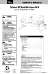
4-BURNER GAS GRILL
WITH SIDE BURNER
Master Forge & M Design® is a
registered trademark of LF, LLC.
All rights reserved.
MODEL #1010048
Español p. 36
WARNING
Improper installation,
adjustment, alteration, service
or maintenance can cause
injury or property damage.
Read this instruction manual
thoroughly before installing or
servicing this equipment.
WARNING
1. Do not store or use gasoline
or and liquids in the vicinity of
this or any other appliance.
2. An LP tank not connected for
use should not be stored
in the vicinity of this or any
other appliance.
DANGER
If you smell gas:
1. Shut off gas to the appliance.
3. Open the lid.
4. If the odor continues, keep
away from the appliance and
immediately call your gas
WARNING
For Outdoor Use Only
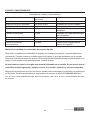
ATTACH YOUR RECEIPT HERE
Serial Number _________________________
Purchase Date _________________________
Questions, problems, missing parts? Before returning to your retailer, call our
customer service department at 1-800-963-0211, 8 a.m. - 6 p.m., EST,
Monday - Thursday, 8 a.m. - 5 p.m., EST, Friday.
AB13574
1
lowes.com/masterforge
®
TABLE OF CONTENTS
Safety Information . . . . . . . . . . . . . . . . . . . . . . . . . . . . . . . . . . . . . . . . . . . . . . . 3
Package Contents . . . . . . . . . . . . . . . . . . . . . . . . . . . . . . . . . . . . . . . . . . . . . . . 5
Hardware Contents . . . . . . . . . . . . . . . . . . . . . . . . . . . . . . . . . . . . . . . . . . . . . . . 7
Preparation . . . . . . . . . . . . . . . . . . . . . . . . . . . . . . . . . . . . . . . . . . . . . . . . . . . 7
Assembly Instructions . . . . . . . . . . . . . . . . . . . . . . . . . . . . . . . . . . . . . . . . . . . . . 8
Installation Instructions . . . . . . . . . . . . . . . . . . . . . . . . . . . . . . . . . . . . . . . . . . . 17
Operating Instructions . . . . . . . . . . . . . . . . . . . . . . . . . . . . . . . . . . . . . . . . . . . . 21
Care and Maintenance . . . . . . . . . . . . . . . . . . . . . . . . . . . . . . . . . . . . . . . . . . . . 24
Troubleshooting . . . . . . . . . . . . . . . . . . . . . . . . . . . . . . . . . . . . . . . . . . . . . . . 30
Warranty . . . . . . . . . . . . . . . . . . . . . . . . . . . . . . . . . . . . . . . . . . . . . . . . . . . . 32
Exploded View . . . . . . . . . . . . . . . . . . . . . . . . . . . . . . . . . . . . . . . . . . . . . . . . 33
Replacement Parts List. . . . . . . . . . . . . . . . . . . . . . . . . . . . . . . . . . . . . . . . . . . . 34
lowes.com/masterforge
2
®
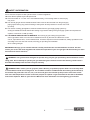
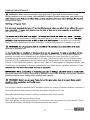
SAFETY INFORMATION
Please read and understand this entire manual before attempting to assemble, operate
or install the product. If you have any questions regarding the product, please call
customer service at 1-800-963-0211, 8:00 am to 6:00 pm, EST, Monday - Thursday, 8:00
a.m. to 5:00 p.m., EST, Friday.
1. The installation of this appliance must conform with local codes or, in the absence of local
codes, with either the National Fuel Gas Code, ANSI Z223.1/NFPA 54, or Natural Gas and Propane
Installation Code, CSA/CGA-B149.1.
2. This grill is intended for use outdoors and should not be used in a building, garage or any
other enclosed or covered area.
3. This outdoor grill is not intended for installation in or on recreational vehicles and/or boats.
4. A minimum clearance of 48 in. from combustible constructions to the sides of the grill and
48 in. from the back of the grill to combustible constructions must be maintained. This outdoor cooking gas
appliance must not be placed under overhead combustible construction.
5. The use of an electrical source requires that when installed, the grill must be electrically
grounded in accordance with local codes or, in the absence of local codes, with ANSI/NFPA 70, or the
Canadian Electrical Code, CSA C22.1. Keep electrical supply cords and fuel supply hose away from
heated surfaces.
6. Inspect the hoses before each use for excessive abrasion or wear, or cut that may affect safe operation
of the grill. If there is evidence of excessive abrasion or wear, or the hose is cut, it must be replaced
manufacturer.
7.
mable vapors and liquids.
8.!
9. Keep the ventilation openings of the tank enclosure free and clear from debris.
10. Check all had connections for leaks with a soapy water solution and brush.
!""
11. Never use charcoal in the grill.
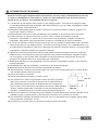
12. Never use the grill in windy areas.
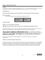
18 in.
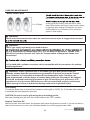
13. Only a 20 lb. LP- gas cylinder is allowed. The cylinder must be
12.2 in.
"$%''(
Cylinders of the U.S. Department of Transportation (D.O.T)
or the National Standard of Canada, CAN/CSA-B339, Cylinders, Spheres
8 in.
and Tubes for Transportation of Dangerous Goods; and Commission.
13.9 in.
A 20 lb. LP-Gas cylinder’s dimensions are:
14. Never use the grill without the drip tray installed and hung under the burner box.
+
"<
15. Use only the gas pressure regulator supplied with this appliance. This regulator is a set for
an outlet pressure of 11.0 wc.
16.The cylinder used must include a collar to protect the cylinder valve.
lowes.com/masterforge
3
®
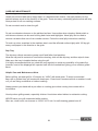
SAFETY INFORMATION
17. Do not store a spare LP-Gas cylinder under or near this appliance.
18.!=>
19.?@HJQ@H=QR
V
may occur.
20. The natural gas grill and its individual shutoff valve must be disconnected from the gas supply
piping system during any pressure testing of that system at test pressures in excess of 0.5 PSI
(3.5 KPa).
21. The outdoor cooking gas appliance must be isolated from the gas supply piping system by
closing its individual manual shutoff valve during any pressure testing of the gas supply system at test pressures
equal to or less than 1/2 PSI (3.5 kPa).
22. CALIFORNIA PROPOSITION 65 WARNING: The burning of gas cooking fuel generates
some byproducts which are on the list of substances known by the state of California to cause
cancer, reproductive harm, or other birth defects. To reduce exposure to these substances, always operate this unit
according to the use and care manual, ensuring you provide good ventilation
when cooking with gas.
IMPORTANT: We urge you to read this manual carefully and follow the recommendations enclosed. This will
ensure you receive the most enjoyable and trouble-free operation of your new gas grill. We also advise you retain
this manual for future reference.
!"#$
%$
rating plate. Do not attempt to operate your grill with other gases. Failure to follow this warning could lead to a
&
''
!"()$*+/;)$$
*+)$<$$
''
%*+)/
hot summer day, tank left in the sun, etc.) can cause LP gas to be released by the pressure relief valve on the
)$
$$*+%
)
$%>'@(%
%
$$*+)
lowes.com/masterforge
4
®
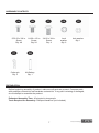
PACKAGE CONTENTS
lowes.com/masterforge
5
®
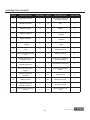
PACKAGE CONTENTS
PART
DESCRIPTION
QUANTITY PART
DESCRIPTION
QUANTITY
A
Warming rack
1
P
Cart front panel bottom
1
B
Cooking grate
2
Q
Axle
1
C
Flame tamer
4
R
Wheel
2
D
Grill Head
1
S
Corner brace right
1
E
Left side shelf
1
T
Cart leg front right
1
F
Hood stop left
1
U
Cart leg back right
1
G
Cart side brace
2
V
Grease tray bracket right
1
H
Cart leg back left
1
W
Control knob
1
I
Grease trap bracket left
1
X
Side burner knob bezel
1
J
Cart leg front left
1
Y
Hood stop right
1
K
LP tank barrier bar
1
Z
Side burner shelf
1
L
Corner brace left
1
A1
Grease cup
1
M
Cart base
1
B1
Grease tray
1
N
Cart front panel bracket
1
C1
Side burner
1
O
Cart front panel top
1
D1
Cart back brace
1
lowes.com/masterforge
6
®
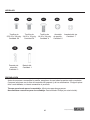
HARDWARE CONTENTS
5/32-32 x 3/8 in. 1/4-20 x 1/2 in.
Screw
Screw
Qty. 49
Qty. 24
Cotter pin
Qty. 3
1/4-20 x 3/4 in.
Screw
Qty. 4
Lock
washer
Qty. 6
Axle washer
Qty. 1
AA Battery
Qty. 1
PREPARATION
Before beginning assembly of product, make sure all parts are present. Compare parts
with package contents list and hardware contents list. If any part is missing or damaged,
do not attempt to assemble the product.
Estimated Assembly Time: 40 minutes by two people
Tools Required for Assembly: Phillips screwdriver (not included).
lowes.com/masterforge
7
®
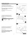
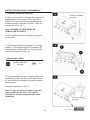
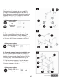
ASSEMBLY INSTRUCTIONS
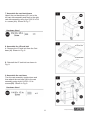
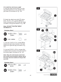
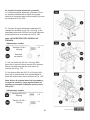
1. Assemble the grill hood
A. Remove the hood hinge screws from
the grill head (D), then remove the hood
from the grill head and set it aside. Shown in Fig.
1A .
Note: DO NOT OPEN THE HOOD PROR TO
COMPLETING STEP A.
B. Remove all of the parts from inside of
the grill head.
C. Attach the hood stop left (F) and hood
stop right (Y) to the grill head (D) using
four 5/32-32 x 3/8 in. screws (AA). Shown
in Fig. 1B.
Hardware Used
5/32-32 x 3/8 in.
Screw
x4
D. Reinstall the hood to the grill head (D)
above the hood stops using the two
previously removed hood hinge screws.
Shown in Fig. 1C
Note: The hood is reinstalled in a higher
position than when it was removed. The
lower position was for shipping
purposes only.
lowes.com/masterforge
8
®
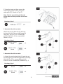
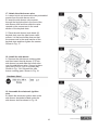
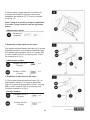
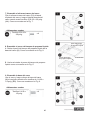
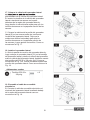
E. Open the hood and then secure the
hood hinge screws in place using two
cotter pins (FF). Shown in Fig. 1D.
Note: Put the assembled grill & hood
to the side and then proceed to the next
steps.
Hardware Used
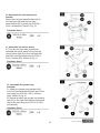
2. Assemble the left cart side
Attach the cart leg back left (H) and cart
leg front left (J) to the cart side brace (G)
using four 1/4-20 x 1/2 in. screws (BB)
and four 5/32-32 x 3/8 in. screws (AA).
Shown in Fig. 2.
Hardware Used
5/32-32 x 3/8 in.
Screw
x4
1/4-20 x 1/2 in.
Screw
x4
3. Assemble the left cart side
A. Attach the cart leg back right (U) and the cart
leg front right (T) to the Cart side brace (G) using
four 1/4-20 x 1/2 in. screws (BB) and four
5/32-32 x 3/8 in. screws (AA). Shown in Fig. 3.
Hardware Used
5/32-32 x 3/8 in.
Screw
x4
1/4-20 x 1/2 in.
Screw
x4
lowes.com/masterforge
9
®
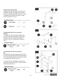
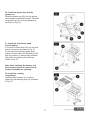
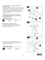
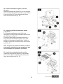
4. Assemble the wheels
Slide the axle (Q) through one wheel (R)
and then through the right cart side and
then the second wheel (R). Secure in place
using the axle washer (EE) and a cotter
pin (FF). Shown in Fig. 4.
Hardware Used
5. Assemble the front cart panel
bottom
A. Attach the cart front panel bottom (P)
to the left cart side assembly and then to
the right cart side assembly using four
5/32-32 x 3/8 in. screws (AA). Shown in
Fig. 5.
Hardware Used
6. Assemble the front cart panel
top
B. Attach the cart front panel top (O) to the
left cart side assembly and then to the right
cart side assembly using four 5/32-32 x 3/8
in. screws (AA). Shown in Fig. 6.
C. Attach the top and bottom cart panels
together using two 5/32-32 x 3/8 in. screws
(AA). Shown in Fig. 6.
Hardware Used
lowes.com/masterforge
10
®
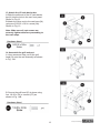
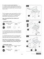
7. Assemble the cart back brace
Attach the cart back brace (D1) on to the
left cart side assembly and then to the right
cart side assembly using four 5/32-32 x 3/8
in. screws (AA). Shown in Fig. 7.
Hardware Used
LP tank bolt
8. Assemble the LP tank bolt
A. Remove the LP tank bolt from the Cart
base (M). Shown in Fig. 8.
LP tank bolt
B. Reinstall the LP tank bolt as shown in
Fig. 8.
9. Assemble the cart base
Turn the cart assembly upside down and
then attach the cart base (M) to the cart
assembly using eight 1/4-20 x 1/2 in.
screws(BB). Shown in Fig. 9.
Hardware Used
lowes.com/masterforge
11
®
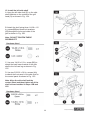
10. Assemble the cart front panel
bracket
Attach the cart front panel bracket (N) to
the cart base (M) and the cart front
panel bottom (P) by using two 5/32-32 x
3/8 in. screws(AA). Show in Fig. 10.
Hardware Used
11. Assemble the corner brace
E. Turn the cart right side up and then
attached the corner brace left (L) and the
corner brace right (S) to the cart base (M)
and back cart legs using three 5/32-32 x
3/8 in. screws (AA). Shown in Fig 11.
Hardware Used
12. Assemble the grease tray
brackets
A . Attach the grease tray bracket left(I)
to the left front and the left back legs of the
cart using four 5/32-32 x 3/8 in. screws
(AA). Shown in Fig 12.
B. Repeat to attach the grease tray bracket
right (V) to the right front and the right back
legs of the cart using four 5/32-32 x 3/8 in.
screws (AA).
Hardware Used
lowes.com/masterforge
12
®
13. Attach the LP tank barrier bar
A.Slide the solid end of the LP tank barrier
bar (K) into the hole in the cart front panel.
Shown in Fig 13.
B.Attach the other end to the cart base (M)
using one 5/32-32 x 3/8 in. screw (AA).
Shown in Fig. 13.
Note: Make sure all cart screws are
securely tightened before proceeding to
the next steps.
Hardware Used
14. Assemble the grill and cart
A. Have someone help you lift the grill
head (D) onto the cart assembly as shown
in Fig. 14A.
B. Secure the grill head (D) in place using
four 1/4-20 x 3/4 in. screws (CC) as
shown in Fig. 14B.
Hardware Used
lowes.com/masterforge
13
®
15. Install the left side shelf
A. Hang the left side shelf (E) on the side
shelf brackets on the outside of the grill
head (D) as shown in Fig. 15A.
B. Attach the shelf using three 1/4-20 x 1/2
in. screws(BB)and three lock washers
(DD)through the holes on inside of the
grill as shown in Fig. 15B.
Note: DO NOT TIGHTEN THESE
SCREWS YET.
Hardware Used
C. Use one 1/4-20 x 1/2 in. screw (BB) to
attach the back lower bracket of the side
shelf to the left cart leg as shown in Fig.
15C.
D. Use two 5/32-32 x 3/8 in. screws (AA)
to attach the front panel of the side shelf to
the control panel as shown in Fig. 15C.
Note: Align the side shelf and the
control panel and then tighten all of the
shelf screws installed in steps 15B and
15C.
Hardware Used
lowes.com/masterforge
14
®
16. Install the side burner shelf
A. Hang the side burner shelf (Z) on the
side shelf brackets on the outside of the
grill head (D) as shown in Fig. 16A.
B. Attach the side burner shelf (Z) using
three 1/4-20 x 1/2 in. screws (BB) and
three lock washers (DD) through the holes
on inside of the grill as shown in Fig. 16B.
Note: DO NOT TIGHTEN THESE
SCREWS YET.
Hardware Used
C. Use one 1/4-20 x 1/2 in. screw (BB)to
attach the back lower bracket of the side
shelf to the right cart leg as shown in Fig.
16C.
D. Use two 5/32-32 x 3/8 in. screws (AA)
to attach the front panel of the side shelf to
the control panel as shown in Fig. 16C
Note: Align the side burner shelf and
the control panel and then tighten all of
the shelf screws installed in steps 16B
and 16C.
Hardware Used
lowes.com/masterforge
15
®
17. Attach the side burner valve
A. Loosen but do not remove the two preinstalled
screws from the side burner valve.
B. Insert the side burner valve screws
through the keyhole slots in the front of the
side burner shelf and then slide the valve
upward so the screws rest in the small
section of the keyhole slots.
C. Place the side burner knob bezel (X)
keyhole slots over the side burner valve
screws. Let the bezel slide down so that
the screws rest in the small section of the
keyhole slots and then tighten the screws.
Shown in Fig. 17.
18. Install the side burner
A. Remove the side burner cooking grate
and then insert the side burner (C1) into
side burner tray and slide the burner tube
over the side burner valve. Secure in place
using two 5/32-32 x 3/8 in. screws (AA).
Shown in Fig. 13A. Reinstall the side
burner cooking grate. Shown in Fig. 18.
Hardware Used
19. Assemble the electronic ignition
wire
B. Attach the electronic ignition wire to the
side burner electrode located under the
side burner shelf as shown in Fig. 19.
lowes.com/masterforge
16
®
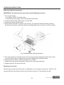
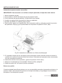
20. Install the grease tray and the
grease cup
Slide the grease tray (B1) into the grease
tray brackets underneath the grill. The slide
the grease cup (A1) into the grease tray
as shown in Fig. 20.
21. Install the side burner knob
and the battery
A. Insert the control knob (W) into the side
burner valve stem as shown in Fig. 21
B. Unscrew the electronic igniter push
button and then insert the AA battery (GG)
with the positive (+) end pointing outward.
Reinstall in the igniter push button as
shown in Fig. 21.
Note: After installing the battery, test
the electronic igniter to make sure all
burner electrodes are sparking.
22. Install the cooking
components
?{|}"
grates (B) and warming rack (A) as shown
in Fig. 22.
lowes.com/masterforge
17
®
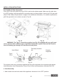
INSTALLATION INTRUCTIONS
For Portable LP-Gas Connection
From front of the cart, place foot ring of 20 lb. tank into the bottom panel. Make sure the tank valve
~~""R>
"
(See LP Gas Safety Requirements on page 24 for additional information). It is unsafe to operate the
grill if the gas tank is not vertical, as seen in Fig. 24.
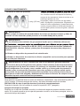
WARNING: The Type 1 connective coupling (see Fig. 25) supplied with your grill must
not be replaced with a different type of grill/tank connection system. Removal will result in
%'[)[
Hand Wheel
External
Thread
Thermally Sensitive
Nut
Propane
Regulator
Type I
Valve
Fig. 25
The propane tank valve connection sipplied with this grill incorporates four important safe gaurds.
Hand Assembly, Hand Disassembly, Excess Flow Control and temperature-Activated Shut-Off.
a. Hand Assembly
1. Make certain the tank valve and all the appliance valves are in the “OFF” position.
lowes.com/masterforge
18
®
INSTALLATION INSTRUCTIONS
2. When connecting the regulator/burner valve assembly to the tank valve, turn the large plastic
nut clockwise until it stops.
(
4. HAND TIGHTEN ONLY.
b. Hand Disassembly
1. Make certain the tank valve and all the appliances valves are in the “OFF” position.
2. Turn the large plastic nut counterclockwise until it is disassembled.
3. HAND LOOSEN ONLY.
c. Excess Flow Control
R!
R
R!!
?"!
!!
surge of pressure will cause the device to activate. The device will remain closed until the pressure is
<
1. Make sure all burner valves are “OFF”.
2. Open the tank valve and wait 5 seconds.
d. Temperature-Activated Shut-Off
The large plastic nut on the regulator assembly is designed in coordination with a check valve in the
"!!
R>>>~?!
"
propane tank. Never attempt to use damaged equipment.
IMPORTANT: Before using a fresh tank of gas, please check leakage around the connections
according to section “Checking Gas Leaks” on page 23 and make sure there is no leakage or
vapor accumulation in the cabinet. Make sure all opening around side walls are not blocked.
IMPORTANT: Place dust cap on cylinder valve outlet whenever the cylinder is not in use.
Only install the type of dust cap on the cylinder valve outlet that is provided with the cylinder
valve. Other types of caps or plugs may result in leakage of propane.
Gas Requirements
The grill is set and tested at the factory for use with LP gas only. The rating plate is located on the
inside panel of the left door.
lowes.com/masterforge
19
®
INSTALLATION INSTRUCTIONS
LP Gas
If your grill is for LP gas, the regulator supplied is set for 11 in. water column (WC) and is for use with
LP gas only. The factory-supplied regulator and hose must be with a 20 lb. LP gas tank.
LP GAS System
Contact your gas supplier for special regulator for bulk gas that fuels other appliances
Gas Consumption
Total gas consumption of this grill with the burner(s) on “HIGH”
Burner Type
Main Burners
Side Burner
BTU/HR
10,000 x 4
12,000 x 1
Locating the Grill
Clearance to Combustible Construction
Warning: Do not place grill under overhead, unprotected combustible surfaces.
A minimum clearance of 48 in. from the sides of the grill and a minimum clearance of 48 in. from the
back of the grill to adjacent vertical combustible constructions must be maintained.
. Do not operate the grill inside a
building, garage, recreational vehicle, screened porch or any enclosed area. Keep the grill away from
ventilation air around the grill.
However, the manufacturer strongly suggests a 6 ft. clearance of the grill to combustible
constructions.
Clearance to Noncombustible Construction
A minimum clearance of 48 in. from the back of the grill above the cooking surface to noncombustible
constructions is required to allow the grill hood to open completely. A minimum of 48 in. clearance to
the sides of the grill above the cooking surface to noncombustible constructions is recommended.
The grill can be installed directly next to noncombustible construction below the cooking surface.
lowes.com/masterforge
20
®
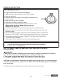
OPERATING INSTRUCTIONS
Grill Lighting Instructions
To Light the Main Burner and the Side Burner
1. M
ake sure the control knobs are in the “OFF” position.
2. Open the grill hood.
3. Check the ignition pin position and distance between the pin
and the burner.
4. Make sure the drip tray is installed.
5. Open the LPG tank or natural gas valve.
6. Light each burner separately. Turning on two burner valves
connection (LP grills only).
7. Push the control knob in and turn the knob to the left to “HIGH” position.
8. Push and turn burner control knob to “HIGH” and immediately press and hold
electronic igniter.
9. If the burner does not ignite, within 5 seconds immediately turn the control knob
back to the “OFF” position. Wait 5 minutes and repeat step 7 two or three times.
10. If the burner still does not ignite, TURN OFF THE GAS. WAIT 5 MINUTES
for excess gas to dissipate.
11. If the burner still can’t be lit refer to the Troubleshooting section.
Replacing the battery
1.
Unscrew the electrical ignition button and remove the old battery.
2.
Replace with a new AA battery.
the side of the cap.
WARNING:
1. Make sue the hood is completely open each time you attempt to light the grill. Failure to
open the hood could lead to delayed ignition resulting in bodily harm.
CAUTION: It is important to inspect the full length of the gas line hose. If it is evident these is
excessive abrasion or wear, or the hose is cut, the hose must be replaced prior to the appliance being used.
If required, check your parts list for the proper replacement hose assembly.
lowes.com/masterforge
21
®
OPERATING INSTRUCTIONS
Matching Lighting Instructions
IMPORTANT: The hood must be open when match lighting any burner.
1. Turn on gas supply.
a. If portable, at the LP cylinder valve.
b. If permanent gas supply, at the manual gas shutoff valve.
%!
3. Access the match clip with chain.
4. Attach either the match or paper to the clip (Fig. 26), light the match and insert it close to
the ports of the burner, and push and turn the depressed knob to the left to “HIGH” position.
Fig. 26 Match/Paper Lighting Illustration
5. The center burner (if needed) can be lit from center grid by inserting the match clip into the
%
6. Depress burner valve for that burner and turn to “HIGH”.
7. Observe that the burner has ignited. Remove the match and extinguish.
8. Repeat steps 2-6 for the next burner.
Breaking in Your Grill
+
!{}@?(Q>
minutes with the hood down and then turn the main burners off. This tempers the grill.
lowes.com/masterforge
22
®
OPERATING INSTRUCTIONS
Preheating Grill
It is extremely important that your grill be up to temperature before you begin using it. After lighting,
close the hood and preheat the grill on “HIGH” for 15 minutes. This preheating will ensure that the
cooking grid and grate are hot enough for proper grilling.
CAUTION: Do not cover the grids during the preheating period.
damage and bodily harm.
Open or closed hood for grilling
Cooking with the lid open or closed is a matter of personal preference. Cooking with the lid
closed is recommended if you enjoy cooking at maximum “searing” temperatures. This
the lid-open method.
We recommend always cooking with the lid CLOSED if you are in a windy area or colder
and cooking performance. Try different cooking methods on your grill to
determine which suits your needs best.
Checking Gas Leaks
Before operating your grill, after refueling, check carefully to be certain that all connections
are tight and there are no gas leaks.
1. Make 2-3 ounces of leak solution by mixing liquid dishwashing soap with water.
2. Make certain all control knobs are in the “OFF” position.
4. If bubbles appear, there is a leak. Proceed to step 5.
5. Turn the gas off and tighten all connections.
7. If bubbles continue to appear, turn the gas off. Contact customer service.
WARNING
explosion and bodily harm.
with approved leak-proof sealing compound or plumber’s tape.
lowes.com/masterforge
23
®
CARE AND MAINTENANCE
Burner Flame Check
the section on cleaning burner tubes and ports.
1 in. (2.5cm)
cooking grids and cooking rack with warm, soapy
water. Rinse and dry thoroughly. Season with cooking
oil regularly. After cooking is completed, turn grill to
HIGH setting for 3 to 5 minutes to burn off excess
grease or food residue.
WARNING
Check and clean burner/venturi tubes for insects and insect nests. A clogged tube can lead
WARNING
The LP gas supply cylinder(s) to be used must be:
the U.S. Department of Transportation (D.O.T) or the National Standard of Canada, CAN/
CSA-B339, Cylinders, Spheres and Tubes for Transportation of Dangerous Goods; and
Commission
(c) Provided with a cylinder connection device compatible with the connection for outdoor
cooking appliances.
WARNING: Please remember this is an outdoor gas grill. Many areas of the grill
generate extreme heat. We have taken every precaution to protect you from the contact
areas. However, it is impossible to isolate all high-temperature areas. Therefore, use
good judgment and a certain degree of caution when grilling on this product. We suggest
a covered, protected hand during operation of grill. Do not move your grill when it is in
operation or hot to the touch. Wait until your unit is turned off and properly cooled down
before moving it. Failure to follow this warning could result in personal injury.
Post Heating
To keep the grates free of charred food remains, run the grill on “HIGH” for 15 minutes after cooking
is complete and food has been removed.
CAUTION: Do not cover the grill during the post heating period.
After post heating your grill, turn the control knobs to the “OFF” position.
Propane Tank Shut-Off
After the burner box cools down, the propane tank valve should also be closed. If you do not want to
wait for the burner box to cool, use a covered hand to turn off the propane tank valve.
lowes.com/masterforge
24
®
CARE AND MAINTENANCE
WARNING
mitt or allowing the grill to cool down. Failure to follow this warning could result in a severe
burn.
LP Gas Safety Requirements
For LP gas grills, the LP gas supply tank to be used must be: Constructed and marked in accordance
National Standard of Canada, CAN/CSA-B339 Cylinders, Spheres and Tubes for Transportation of
Device (OPD).
The tank should be 12 in. in diameter and 18-1/2 in. tall and be equipped with a
The tank supply system must be arranged for vapor withdrawal.
The tank used must include a collar to protect the cylinder valve.
Do not operate the gas grill indoors or in any enclosed area. If the gas grill is not in use, the gas must
be turned off at the supply tank. If the grill is to be stored indoors, disconnect the gas supply tank and
store the tank in an upright position in a cool, well-ventilated outdoor location away from your grill or
any other heat source.
that may affect the safe operation of the grill. Only the factory supplied hose and regulator must be
.
LP tank should be securely locked by the safety tank ring at all times. An unlocked tank may fall or tilt
which can cause injury or property damage. It is recommended to lock the tank all the time.
After positioning the tank in the opening, lower the safety tank ring to lock the tank. Use only a 20 lb.
gas tank.
WARNING
The pressure regulator and hose assembly supplied with the outdoor cooking gas appliance
by the outdoor cooking gas appliance manufacturer.
lowes.com/masterforge
25
®
CARE AND MAINTENANCE
Handling the Liquid Propane Tank Safely
Remember to handle your portable liquid propane tank carefully when you take it to your dealer
!
V%"
V
When transporting the tank to your local propane gas dealer, make sure the valve is closed tightly
and the protective cover is in place. Position the tank securely in an upright position so it will not roll
around your vehicle.
?"
!"
""
+
!"!!!"
a vehicle that may become overheated by the sun.
Your local liquid propane gas dealer will gladly offer you additional safety tips.
Storing the Liquid Propane Tank Safely
Whether you are between cross-country treks in your recreational vehicle or looking for a place to
keep the liquid propane tank to provide fuel for your outdoor grill, keep in mind some basic safety
rules about storing portable liquid propane tanks:
Do not store the tanks (whether full or empty) inside your home, the living area of an R.V., a garage,
basement or workshop. It is unlikely that liquid propane will leak from the tanks. If it should leak, the
fuel could be exposed to sparks from automobiles, power tools or other appliances. When storing or
transporting your LP tank, it must remain in an upright position. Never lay your LP tank down on its
side whether it is full or empty. Never store a spare tank under or near your grill.
]^<>"
)'$
valve on your liquid propane gas tank.
The best place to store a liquid propane tank is in a shady or protected spot outdoors, behind your
home or garage, or on a screened porch but where it is out of reach of children. Liquid propane will
not evaporate. It is in a strong, closed container. It will not loose any of its clean-burning heat content,
even if left outside year-round.
lowes.com/masterforge
26
®
CARE AND MAINTENANCE
WARNING: When not connected to your grill, the LP gas tank must be stored in an
upright position in a cool, shady, well-ventilated, outdoor location away from your grill or any
and personal injury.
tank can be dangerous.
weights should be readjusted to a weight that would allow up to 80% of the total weight.
. If the tank is not completely
empty, the scale readjustment must be changed to consider the propane (LP) already in the tank.
capacity or propane (LP).
weather causes the warming of the LP tank, (a hot day, tank life in sun or stored indoors) internal
pressure is created due to expansion of the propane which in turn may cause the LP gas to be
released through the pressure relied valve on the tank. The pressure relief valve is a safety device
required on 20 lb. propane tanks by the Department of Transportation or the National Standard of
Canada, CAN/CSA-B339 Cylinders, Spheres and Tubes for Transportation of Dangerous Goods; and
Commission, as applicable, to prevent a catastrophic tank failure due to excessive pressure. LP gas
approved leak-proof sealing compound or plumber’s tape. After making connections, check all
joints for leaks using a soapy water solution and a brush.
Stainless Steel
The gas grill is made of stainless steel. Stainless steel is non-rusting in certain conditions; therefore, a
cover and stainless steel cleaner should be used when the grill is not in use.
Wipe with stainless steel cleaner on all non-cooking surfaces once a month.
Never clean the stainless steel when it is hot.
After initial grilling, certain areas of the grill (i.e. the vents, hood and burner box) may discolor. This is
a normal discoloration caused by the intense heat from the burners.
lowes.com/masterforge
27
®
CARE AND MAINTENANCE
Specks of grease can gather on the surface of the stainless steel and get baked-on. These can
usually be removed with warm soapy water or a stainless steel cleaner. Use light pressure on the
pad and always scrub in the direction of the grain. There are many outstanding products that will help
clean protect on all non-cooking surfaces.
Do not use steel wool to clean the grill.
Do not use abrasive cleaners on the polished surface. Use caution when cleaning. Metal polish or
"
!V
!~!V
To touch up minor scratches in the stainless steel, sand the affected surface lightly with 160 dry grit
emery sand paper in the direction or the grain.
Drip Tray
The drip tray collects excessive grease runoff and fallen food particles.
Allow the tray and its contents to cool before cleaning, slide out the drip tray and then wipe it clean.
Make sure the tray is installed before using the grill.
?
"
!
!
!<""
!
!
Helpful Care and Maintenance Hints
Before grilling, pre-heat grill for 15 minutes on “HIGH” with hood down. To avoid uncontrolled
|"
or if you are using a rotisserie or indirect cooking.
Always protect your hand with a pot mitten or cooking glove when coming into contact with a
hot surface.
Hood up when grilling meats, especially chicken. Hood down when indirect or rotisserie cooking.
NEVER leave your grill unattended while cooking.
After use, close hood, turn burners to “HIGH” for 15 min. for self-cleaning grease burn off.
lowes.com/masterforge
28
®
CARE AND MAINTENANCE
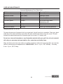
Care and Maintenance Time Table Chart
Grill Item
Painted surface
Stainless surface
All grates
Stainless grates
Porcelain grates
Frequency Based on Normal Use
Twice yearly
Twice yearly
After each use
15 days
15 days
Burner heat tents
Burners
Burner box interior
30 days
90 days
120 days
Cleaning Method
Car wax
Stainless cleaner
Burn off and wipe
Wire brush/Dishwasher safe
Scrub pad soapy water/
Dishwasher safe
Wire brush
Wire brush
Interior grill cleaning products
Gauging amount of LP fuel
To gauge the amount of propane fuel in your gas tank, the grill must be in operation. Place your hand
at the top of the tank and slowly move down the side until the tank feels cool to the touch. This will
R
"
_$$`
'^%$
''
[
!"
RV
call the customer service department at 1-800-963-0211, 8 a.m.- 6 p.m., EST, Monday - Thursday,
8 a.m.- 5 p.m., EST, Friday.
lowes.com/masterforge
29
®
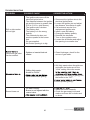
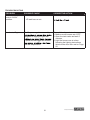
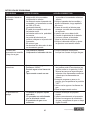
TROUBLESHOOTING
PROBLEM
POSSIBLE CAUSE
CORRECTIVE ACTION
Grill or side cooker
will not light.
1. The ignition wire came off the
electrical igniter/valve.
2. The distance between the ignition
pin and the burner is greater than
5/32 in.-3/16 in. (side burner).
3. The ignition wire is broken.
4. The battery died.
5. The battery is in the wrong
polarity.
6. The electrode tip does not
produce sparks at the burner
port.
7. No gas supplied.
8. Air shutter opening is to big.
1. Reconnect the ignition wire to the
electrical igniter/valve.
2. Loosen the ignition pin and adjust
the distance, then fasten it again.
3. Call customer service for a
replacement ignition wire.
4. Install a new AA battery.
5. Change the battery polarity.
6. Reinstall the electrode.
7. Turn on the regulator valve.
8. Loosen the air shutter and adjust
the opening to a smaller size
1. Spiders or insects block air
shutter.
1. Clean blockages, check for the
source of gas leaks.
yellow and gas odor
can be smelled.
1. Grill fatty meats when the grids are
cold while the knobs are on the
“LOW” setting. Move the meats
1. Grilling fatty meats.
2. Knobs on “HIGH”.
4. Hood closed when grilling.
2. Before you are ready to grilling, turn
the knobs to the “OFF”.
4. Hood up when grilling.
Burner blows out
1. LP tank is empty.
2. Burner is not aligned with the
control valve.
2. Install the burner correctly.
3. Check the gas supply hose and
make sure there are no leaks and
no knots.
lowes.com/masterforge
30
®
TROUBLESHOOTING
PROBLEM
Low heat with the
knob in “HIGH”
position.
POSSIBLE CAUSE
1. Ports are blocked.
CORRECTIVE ACTION
1. Clear ports of any obstructions.
Low heat, LP gas.
The Propane regulator assembly
2. LP tank has run out.
designed to supply the grill with
in pressure can trigger the excess
and low temperature.
Please follow these instructions:
1. Make sure all burners are “OFF”.
2. Open the tank valve and wait 5
minutes.
3. Light the burner one at a time
following the lighting instructions
listed on the door liner and on Page
22.
lowes.com/masterforge
31
®
WARRANTY
Proof of purchase is required to access this warranty program, which is in effect from the date of
|V
!
purchase or after the warranty has expired.
If you have any questions or problems, you can call our customer service department at
1-800-963-0211, 8 a.m. - 6 p.m., EST, Monday - Thursday, 8 a.m. – 5 p.m., EST, Friday.
Limited Warranty
5-Year Warranty on stainless steel burners.
1-Year Warranty on all parts affecting the operation of the gas grill due to damage.
Warranty Provisions:
This warranty is non-transferable and does not cover failures due to misuse or improper installation or
maintenance.
This warranty is for replacement of defective parts only. We are not responsible for incidental or
consequential damages or labor costs.
This warranty does not cover corrosion or discoloration after the grill is used, or lack of maintenance,
hostile environment, accidents, alterations, abuse or neglect.
This warranty does not cover damage caused by heat, abrasive and chemical cleaners, or any
damage to other components used in the installation or operation of the gas grill.
Some states do not allow the limitation or exclusion of incidental or consequential damages,
$
<'$$
legal rights, and you may also have other rights that vary from state to state.
lowes.com/masterforge
32
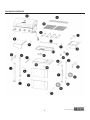
®
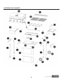
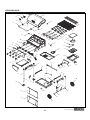
EXPLODED VIEW
lowes.com/masterforge
33
®
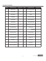
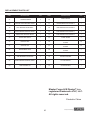
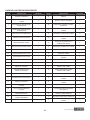
REPLACEMENT PARTS LIST
PART
DESCRIPTION
QTY.
PART
DESCRIPTION
QTY.
1
GRILL HOOD
1
24
KNOB
5
2
HOOD HINGE SCREW
2
25
LEFT SIDE SHELF
1
3
TEMPERATURE GAUGE
BEZEL
1
26
LEFT SIDE SHELF FRONT
1
4
TEMPERATURE GAUGE
HEAT INSULATING SPACER
1
27
CART LEG FRONT LEFT
1
5
TEMPERATURE GAUGE
1
28
CART SIDE BRACE
2
6
WARMING RACK
1
29
CART LEG BACK LEFT
1
7
HOOD BUMPER
2
30
GREASE TRAY BRACKET
LEFT
1
8
HOOD HANDLE BEZEL
2
31
CART BACK BRACE
1
9
HOOD HANDLE
1
32
LP TANK BARRIER BAR
1
10
HOOD STOP LEFT
1
33
CART BASE
1
11
HOOD STOP RIGHT
1
34
LP TANK BOLT
1
12
COTTER PIN
4
35
CORNER BRACE LEFT
1
13
FIREBOX
1
36
CART LEG FOOT
2
14
CONTROL PANEL
BRACKET LEFT
1
37
CART FRONT PANEL TOP
1
15
CONTROL PANEL
BRACKET RIGHT
1
38
CART FRONT PANEL BOTTOM
1
16
MAIN GAS MANIFOLD
ASSEMBLY
1
39
WHEEL
2
17
ELECTRONIC IGNITER
1
40
CART FRONT PANEL BRACKET
1
18
CONTROL PANEL
1
41
CART LEG FRONT RIGHT
1
19
SIDE BURNER HOSE
1
42
AXLE
1
20
SIDE BURNER VALVE
1
43
MATCH LIGHT TOOL
1
21
LP REGULATOR
1
44
MATCH LIGHT HOLDER
1
22
SIDE SHELF BRACKET LEFT
1
45
CORNER BRACE RIGHT
1
23
KNOB BEZEL
4
46
CART LEG BACK RIGHT
1
lowes.com/masterforge
34
®
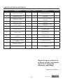
REPLACEMENT PARTS LIST
PART
47
DESCRIPTION
COOKING GRATE
QTY.
PART
DESCRIPTION
QTY.
2
60
MAIN BURNER
4
48
GREASE TRAY BRACKET RIGHT
1
61
MAIN BURNER ELECTRODE A
1
49
SIDE BURNER KNOB BEZEL
1
62
MAIN BURNER ELECTRODE B
1
50
SIDE BURNER CONTROL PANEL
1
63
MAIN BURNER ELECTRODE C
1
51
SIDE SHELF BRACKET RIGHT
1
64
MAIN BURNER ELECTRODE D
1
52
RIGHT SIDE SHELF
1
65
FLAME TAMER
4
53
GREASE TRAY
1
66
AA 5/32-32 X 3/8 in.
SCREW
49
54
GREASE CUP
1
67
BB 1/4-20 X 1/2 in.
SCREW
24
55
SIDE BURNER TRAY
1
68
CC 1/4-20 X 3/4 in.
SCREW
4
56
SIDE BURNER
1
69
DD LOCK WASHER
6
57
SIDE BURNER ELECTRODE
1
70
EE AXLE WASHER
1
58
SIDE BURNER COOKING GRATE
1
71
FF COTTER PIN
3
59
SIDE BURNER LID
1
72
GG AA BATTERY
1
Master Forge & M Design® is a
registered trademark of LF, LLC.
All rights reserved.
Printed in China
lowes.com/masterforge
35
®
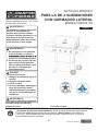
ARTÍCULO #0503231
Master Forge y el diseño de la M son
marcas registradas de LF, LLC. Todos
los derechos reservados.
PARILLA DE 4 QUEMADORES
CON QUEMADOR LATERAL
MODELO #RT2417S
ADVERTENCIA
La instalación, ajuste, alteración,
servicio o mantenimiento
inadecuados pueden causar
lesiones o daños materiales. Lea
este manual de instrucciones
detenidamente antes de instalar
o dar servicio a este equipo.
English p. 1
ADVERTENCIA
1. No almacene ni use gasolina
u otros líquidos o vapores
ningún otro electrodoméstico.
2. Un tanque de propano líquido
que no esté conectado para
usar no debe guardarse cerca
de este ni de ningún otro
electrodoméstico.
PELIGRO
Si siente olor a gas:
1. Apague la entrada de gas a la
parrilla.
2. Apague cualquier llama.
3. Cierre la tapa.
4. Si el olor persiste, manténgase
lejos de la parrilla y llame
inmediatamente al proveedor
del gas o al departamento de
bomberos.
ADVERTENCIA
Para uso en exteriores solamente.
ADJUNTE AQUÍ SU RECIBO
Número de serie _________________________
Fecha de compra _____________________
¿Preguntas, problemas, piezas faltantes? Antes de volver a la tienda, comuníquese
con nuestro departamento de servicio al cliente al 1-800-963-0211, entre 8:00 a.m.
y 6:00 p.m., hora estándar del este, de lunes a jueves y entre 8:00 a.m. y 5:00 p.m.,
hora estándar del este, el viernes.
36
lowes.com/masterforge
®
TABLA DE CONTENIDO
Información de seguridad . . . . . . . . . . . . . . . . . . . . . . . . . . . . . . . . . . . . . . . . . . 38
Contenido del paquete . . . . . . . . . . . . . . . . . . . . . . . . . . . . . . . . . . . . . . . . . . . . 41
Aditamentos. . . . . . . . . . . . . . . . . . . . . . . . . . . . . . . . . . . . . . . . . . . . . . . . . . 42
Preparación . . . . . . . . . . . . . . . . . . . . . . . . . . . . . . . . . . . . . . . . . . . . . . . . . . 42
Instrucciones para el ensamblaje . . . . . . . . . . . . . . . . . . . . . . . . . . . . . . . . . . . . . . 43
Instrucciones para la instalación . . . . . . . . . . . . . . . . . . . . . . . . . . . . . . . . . . . . . . 53
Instrucciones de uso . . . . . . . . . . . . . . . . . . . . . . . . . . . . . . . . . . . . . . . . . . . . . 56
Cuidado y mantenimiento . . . . . . . . . . . . . . . . . . . . . . . . . . . . . . . . . . . . . . . . . . 59
Detección de a problemas . . . . . . . . . . . . . . . . . . . . . . . . . . . . . . . . . . . . . . . . . . 65
Garantía . . . . . . . . . . . . . . . . . . . . . . . . . . . . . . . . . . . . . . . . . . . . . . . . . . . . 67
Vista ampliada . . . . . . . . . . . . . . . . . . . . . . . . . . . . . . . . . . . . . . . . . . . . . . . . 68
*& . . . . . . . . . . . . . . . . . . . . . . . . . . . . . . . . . . . . . . . . . 69
lowes.com/masterforge
37
®
INFORMACIÓN DE SEGURIDAD
Por favor, lea y entienda este manual en su totalidad antes de intentar ensamblar, instalar o usar este
producto. Si tiene alguna pregunta sobre este producto, por favor, llame al departamento de servicio
al cliente al 1-800-963-0211, entre 8:00 a.m. y 6:00 p.m., hora estándar del este, de lunes a jueves, y
entre 8:00 a.m. y 5:00 p.m., hora estándar del este, los viernes.
1. La instalación de este aparato debe cumplir con los códigos locales o, en ausencia de códigos locales,
con el Código Nacional de Gas Combustile, ANSI Z223.1/NFPA 54 o con el Código de Instalación de Gas
Natural y Propano, CSA/CGA-B149.1.
2. R
V
ningún lugar cerrado ni cubierto.
3. Esta parrilla para exteriores no está diseñada para ser instalada en vehículos de recreo ni en botes.
4. Se debe mantener un espacio mínimo de 121,92 cm entre los lados de la parrilla y cualquier
construcción combustible y un mínimo de 121,92 cm entre la parte posterior y cualquier construcción
RV
5.
!<
a tierra de acuerdo con los códigos locales o, en ausencia de códigos locales, con el ANSI/NFPA 70 o con
el Código Eléctrico Canadiense, CSA C22.1. Mantenga los cables de suministro eléctrico y la manguera de
V
6. Inspeccione las mangueras antes de cada uso para detectar abrasión, desgaste excesivo o cortes que
puedan afectar el funcionamiento seguro de la parrilla. Si hay evidencia de abrasión, desgaste excesivo
<
V
7.
V
!
8. $V!
9. Mantenga limpia las aberturas de ventilación del depósito del tanque.
10. !R
V
use una llama abierta para buscar fugas.
11. Nunca use carbón en la parrilla.
12. Nunca use la parrilla en lugares con mucho viento.
45,72 cm
13. Use solamente un cilindro de gas propano líquido de 20 lbs. El cilindro
30,98 cm
para cilindros de propano líquido del Departamento de Transporte de
EE.UU. (DOT) o de la Asociación Canadiense de Normas, CAN/CSA-B339,
20,32 cm
35,30 cm
cilindros, esferas y tubos para el transporte de mercancías peligrosas; y
Comisión. Las dimensiones de un cilindro de gas de propano líquido son:
14. V
VV$
V
15.
!
V
para una presión de salida de 11,0 wc.
16. El cilindro que use debe incluir un collar para proteger la válvula del cilindro.
lowes.com/masterforge
38
®
INFORMACIÓN DE SEGURIDAD
17. V
18. =>
19. Si las instrucciones del No. 17 y del No. 18 no se siguen exactamente, puede ocurrir un fuego y causar graves
lesiones o la muerte.
20. La parrilla de gas natural y su válvula de cierre individual deben estar desconectadas del sistema de tuberías de
suministro de gas durante cualquier prueba de presión del sistema a presiones superiores a 0,5 PSI (3,5 KPa).
21. La parrilla a gas para cocinar en exteriores se debe aislar del sistema de tuberías de suministro de gas cerrando
su válvula de cierre manual individual durante cualquier prueba de presión del sistema de suministro de gas a
presiones iguales o inferiores a 1/2 PSI (3,5 kPa).
22. ADVERTENCIA DE LA PROPUESTA 65 DE CALIFORNIA: El quemar combustible para cocinar a gas genera
algunos subproductos que se encuentran en la lista de sustancias conocidas por el estado de California como
causantes de cánceres, daños al sistema reproductivo u otros defectos congénitos. Para reducir la exposición
a estas sustancias, siempre opere esta unidad de acuerdo con las instrucciones del manual de uso y cuidado,
asegúrese de que exista una buena ventilación cuando cocine con gas.
IMPORTANTE: Le rogamos que lea atentamente este manual y siga las recomendaciones adjuntas.
Esto asegurará que usted disfrutará de la forma más agradable y sin problemas de su nueva parrilla a gas.
También le aconsejamos que guarde este manual para futura referencia.
_}<]"~%$$
$$
%$$$$$$$
de esta advertencia puede provocar un riesgo de incendio y lesiones corporales y anulará la garantía.
ADVERTENCIA: Asegúrese de que el tanque de gas de propano líquido lo llene un distribuidor
de propano de reputación. Un tanque mal llenado o llenado en exceso puede ser peligroso. Un tanque
sobrellenado combinado con el calentamiento del tanque de gas (un caluroso día de verano, un tanque
mantenido bajo el sol, etc.) puede causar que el gas propano líquido se escape por la válvula reguladora de
presión ya que el aumento de temperatura hace que el propano se expanda . El gas propano líquido que sale
`
]
información sobre cómo llenar su tanque de gas.
lowes.com/masterforge
39
®
CONTENIDO DEL PAQUETE
lowes.com/masterforge
40
®
CONTENIDO DEL PAQUETE
PIEZA
DESCRIPCIÓN
DESCRIPCIÓN
CANTIDAD
A
Parrilla para calentar
1
P
Parte inferior del panel
delantero del carro
1
B
Parrilla de cocción
2
Q
Eje
1
C
Difusor de llama
4
R
Rueda
2
D
Tapa de la parrilla
1
S
E
Repisa izquierda
1
T
1
U
F
Tope izquierdo para
la tapa
CANTIDAD PIEZA
Refuerzo esquinero
derecho
Pata delantera derecha
del carro
Pata trasera derecha del
carro
1
1
1
G
Refuerzo izquierdo del
carro
2
V
Soporte derecho de la
bandeja de goteo
1
H
Pata izquierda trasera del
carro
1
W
Perilla de control
1
I
Soporte izquierdo de la
bandeja de goteo
1
X
Moldura de la perilla del
quemador lateral
1
J
Pata izquierda
delantera del carro
1
Y
Tope derecho de la tapa
1
K
Barra de protección
del tanque de propano
líquido
1
Z
Repisa del quemador
lateral
1
L
Refuerzo esquinero
izquierdo
1
A1
Taza de goteo
1
M
Base del carro
1
B1
Bandeja de goteo
1
N
Soporte del panel
delantero del carro
1
C1
Quemador lateral
1
O
Tapa del panel delantero
del carro
1
D1
Refuerzo trasero del
carro
1
lowes.com/masterforge
41
®
HERRAJES
Tornillos de
Tornillos de
Tornillos de
5/32-32 x 3/8 pulg. 1/4-20 x 1/2 pulg. 1/4-20 x 3/4 pulg.
Cantidad: 4
Cantidad: 49
Cantidad: 24
Pasador de
retención
Cantidad: 3
Arandela
de presión.
Cantidad: 6
Arandela del eje.
Cantidad: 1
Batería AA.
Cantidad: 1
PREPARACIÓN
Antes de empezar a ensamblar la parrilla, asegúrese de que todas las partes estén completas.
Compare las piezas con la lista de contenido del paquete y de los aditamentos. Si alguna pieza
falta o está dañada, no intente ensamblar el producto.
Tiempo aproximado para el ensamblaje: 40 minutos para dos personas
Herramientas necesarias para el ensamblaje: Destornillador Phillips (no esta incluido).
lowes.com/masterforge
42
®
INSTRUCCIONES PARA EL ENSAMBLAJE
1. Ensamble la tapa de la parrilla.
tornillo de la bisagra
de la tapa
A. Quite los tornillos de la bisagra de la tapa para
separarla de la parte superior de la tapa de la
parrilla (D), luego quite la tapa separándola de
la parte superior y póngala a un lado. Como se
muestra en la Fig. 1A.
Nota: NO ABRA LA TAPA ANTES DE
COMPLETAR EL PASO A.
B. Quite todas las piezas del interior de la tapa
de la parrilla.
C. Fije el tope izquierdo de la tapa (F) y el tope
derecho (Y) a la parte superior de la parrilla (D)
usando cuatro tornillos 5/32-32 x 3/8 pulg. (AA).
Como se muestra en la Fig. 1B.
Aditamentos usados
Tornillos 5/32-32 x
3/8 pulg.
x4
D. Vuelva a instalar la tapa a la parte superior de
la parrilla (D) sobre los topes de la tapa usando
los dos tornillos de bisagras de la tapa que quitó
anteriormente.
Como se muestra en la Fig. 1C.
Nota: La tapa se vuelve a instalar a un nivel
más elevado del que tenía. La posición
más baja se usó para propósitos de envío
solamente.
tornillo de bisagra
de la tapa
lowes.com/masterforge
43
®
E. Abra la tapa y luego asegure los tornillos de
la bisagra de la tapa en su lugar usando dos
pasadores de retención (FF). Como se muestra
en la Fig. 1D.
Nota: Coloque la parrilla y la tapa ensamblada
a un lado y luego continúe con los siguientes
pasos.
Aditamentos usados
Pasador de
retención
2 Ensamble el lado izquierdo del carro
Fije la pata izquierda trasera del carro (H) y la pata
izquierda delantera (J) al refuerzo lateral del carro
(G) usando cuatro tornillos 1/4-20 x 1/2 pulg. (BB)
y cuatro tornillos 5/32-32 x 3/8 pulg. (AA). Como
se muestra en la Fig. 2.
Aditamentos usados
Tornillos 5/32-32 x
3/8 pulg.
x4
Tornillos 1/4-20 x
1/2 pulg.
x4
3 Ensamble el lado derecho del carro
A. Fije la pata derecha trasera del carro (U) y la
pata derecha frontal (T) al refuerzo lateral del
carro (G) usando cuatro tornillos 1/4-20 x 1/2 pulg.
(BB) y cuatro tornillos 5/32-32 x 3/8 pulg. (AA).
Como se muestra en la Fig. 3.
Herrajes usados
Tornillos 5/32-32 x
3/8 pulg.
x4
Tornillos 1/4-20 x
1/2 pulg.
x4
lowes.com/masterforge
44
®
4. Ensamble las ruedas.
Deslice el eje (Q) a través de una rueda (R)
y luego a través del lado derecho del carro y
luego la segunda rueda (R). Asegúrelo usando la
arandela del eje (EE) y el pasador de retención
(FF). Como se muestra en la Fig. 4.
Aditamentos usados
Arendela del
eje
Pasador de
retención
5. Ensamble el panel inferior frontal del carro
A. Fije el panel inferior frontal del carro (P) al
lateral izquierdo del carro y luego al lateral
derecho del carro usando cuatro tornillos 5/32-32
x 3/8 pulg. (AA). Como se muestra en la Fig. 5.
Aditamentos usados
Tornillos 5/32-32 x
3/8 pulg.
x4
6. Ensamble el panel superior frontal del carro
B. Fije el panel superior frontal del carro (O) al
izquierdo lateral del carro y luego al derecho
lateral del carro usando cuatro tornillos 5/32-32 x
3/8 pulg. (AA). Como se muestra en la Fig. 6.
C. Fije los paneles superior e inferior del carro
usando dos tornillos 5/32-32 x 3/8 pulg. (AA).
Como se muestra en la Fig. 6.
Aditamentos usados
Tornillos 5/32-32 x
3/8 pulg.
x6
lowes.com/masterforge
45
®
7. Ensamble el refuerzo trasero del carro
Fije el refuerzo tracero del carro (D1) al lateral
izquierdo del carro y luego al lateral derecho del
carro usando cuatro tornillos 5/32-32 x 3/8 pulg.
(AA). Como se muestra en la Fig. 7.
Aditamentos usados
Tornillos 5/32-32 x
3/8 pulg.
x4
perno del tanque
de propano
líquido
LP tank
bolt
8. Ensamble el perno del tanque de propano líquido.
A. Retire el perno del tanque de propano líquido de la
base del carro (M). Como se muestra en la Fig. 8.
perno del tanque
de propano líquido
LP tank bolt
B. Vuelva a instalar el perno del tanque de propano
líquido como se muestra en la Fig. 8
9. Ensamble la base del carro
Vire el carro y luego coloque la base del carro
(M) al conjunto usando ocho tornillos de 1/4-20 x
1/2 pulg. (BB). Como se muestra en la Fig. 9.
Aditamentos usados
Tornillos 1/4-20 x
1/2 pulg.
x4
lowes.com/masterforge
46
®
10. Ensamble el soporte del panel frontal del carro
Fije el soporte del panel frontal del carro (N)
a la base del carro (M) y a la parte inferior del panel
frontal (P) usando dos tornillos de 5/32-32 x 3/8 pulg.
(AA). Como se muestra en la Fig. 10.
Aditamentos usados
Tornillos 5/32-32 x
3/8 pulg.
x2
11. Ensamble el refuerzo esquinero
E. Vire el carro con el lado derecho hacia arriba
el refuerzo derecho esquinero (S) a la base del
carro (M) y a las patas traseras del carro usando
tres tornillos de 5/32-32 x 3/8 pulg. (AA). Como se
muestra en la Fig. 11.
Aditamentos usados
Tornillos 5/32-32 x
3/8 pulg.
x6
12. Ensamble los soportes de la bandeja
de goteo
A. Fije el soporte izquierdo de la bandeja de goteo
(I) a las patas izquierdas delantera y trasera del
carro usando cuatro tornillos de 5/32-32 x 3/8 pulg.
(AA). Como se muestra en la Fig. 12.
Punta de
la bandeja de goteo (V) a las patas derechas delantera y trasera del carro usando
cuatro tornillos de 5/32-32 x 3/8 pulg. (AA).
Aditamentos usados
Tornillos 5/32-32 x
3/8 pulg.
x8
lowes.com/masterforge
47
®
13. Fije la barra de contención del tanque de
propano líquido
A. Deslice el extremo sólido de la barra de contención
del tanque de propano líquido (K) en el hoyo del panel
frontal del carro. Como se muestra en la Fig. 13.
B. Fije el otro extremo a la base del carro (M) usando
un tornillo de 5/32-32 x 3/8 pulg. (AA). Como se
muestra en la Fig. 13.
Nota: Asegúrese de que todos los tornillos
estén bien apretados antes de continuar con
los próximos pasos.
Aditamentos usados
Tornillo 5/32-32 x
3/8 pulg.
x1
14. Ensamble la parrilla y el carro
A. Busque ayuda para levantar la tapa de la
parrilla (D) y colocarla sobre el carro como se
muestra en la Fig. 14A.
B. Refuerce la tapa de la parrilla (D) usando
cuatro tornillos de 1/4-20 x 3/4 pulg. (CC) como
se muestra en la Fig. 14B.
Aditamentos usados
Tornillos 1/4-20 x
4/5 pulg.
x4
lowes.com/masterforge
48
®
15. Instale la repisa lateral izquierda
A. Cuelgue la repisa lateral izquierda (E) sobre
los soportes para la repisa lateral en el lado de la
parte superior de la parrilla (D) como se muestra
e la Fig. 15A.
B. Fije la repisa usando tres tornillos de 1/4-20 x
1/2 pulg. (BB) y tres arandelas de presión (DD)
poniéndolas en los hoyos en el interior de la
parrilla como se muestra en la Fig. 15B.
Nota: NO APRIETE ESTOS TORNILLOS
TODAVÍA.
Aditamentos usados
Tornillos 1/4-20 x
1/2 pulg.
Arandelas
de presión
x4
x3
C. Use un tornillo de 1/4-20 x 1/2 pulg. (BB) para
unir el soporte inferior trasero de la repisa lateral
a la pata izquierda del carro como se muestra en
la Fig. 15C.
D. Use dos tornillos de 5/32-32 x 3/8 pulg. (AA)
para unir el panel frontal de la repisa lateral al
panel de control como se muestra en la Fig. 15C.
Nota: Alinee la repisa lateral y el panel de
control y luego apriete todos los tornillos de
la repisa instalados en los pasos 15B y 15C.
Aditamentos usados
Tornillos 5/32-32 x
3/8 pulg.
x2
Tornillo 1/4-20 x
1/2 pulg.
x1
lowes.com/masterforge
49
®
16. Instale la repisa lateral del quemador
A. Coloque la repisa lateral del quemador (Z) en
los soportes laterales de la repisa en la parte
exterior de la parte superior de la parrilla (D) como
se muestra en la Fig. 16A.
B. Coloque la repisa lateral del quemador (Z)
usando tres tornillos de 1/4-20 x 1/2 pulg. y tres
arandelas de presión (DD) en los hoyos interiores
de la parrila como se muestra en la Fig. 16B.
Nota: NO APRIETE ESTOS TORNILLOS
TODAVÍA.
Aditamentos usados
Aditamentos usados
Tornillos 1/4-20 x
1/2 pulg.
Arandela
de presión
x3
x3
C. Use un tornillo de 1/4-20 x 1/2 pulg. (BB)
para unir el soporte inferior trasero de la respisa
lateral a la pata derecha del carro como se
muestra en la Fig. 16C.
D. Use dos tornillos de 5/32-32 x 3/8 pulg. (AA)
para unir el panel frontal de la repisa lateral al
panel de control como se muestra en la Fig. 16C.
Nota: Alinee la respisa lateral del quemador y
el panel de control y luego apriete todos los
tornillos de la repisa instalados en los pasos
16B y 16C.
Aditamentos usados
Tornillos 5/32-32 x
3/8 pulg.
x2
Tornillo 1/4-20 x
1/2 pulg.
x1
lowes.com/masterforge
50
®
17. Coloque la válvula del quemador lateral
preinstalados de la válvula del quemador lateral.
B. Inserte los tornillos de la válvula del quemador
lateral a través de las ranuras en la parte
delantera de la repisa del quemador lateral y
luego deslice la válvula hacia arriba para que los
tornillos descansen en la pequeña sección de las
ranuras.
C. Coloque la moldura de la perilla del quemador
lateral (X) en las ranuras sobre los tornillos de
la válvula del quemador lateral. Deje que la
moldura se deslice hacia abajo para que los
tornillos descansen en la pequeña sección de
las ranuras y luego apriete los tornillos. Como se
muestra en la Fig. 17.
18. Instale el quemador lateral
A. Quite la parrilla de cocción del quemador lateral y
luego coloque el quemador lateral (C1) en la bandeja
del quemador lateral y deslice la tubería del quemador
sobre la válvula del quemador lateral. Apriételo usando
dos tornillos de 5/32-32 x 3/8 pulg. (AA). Como se
muestra en la Fig. 13A. Vuelva a instalar la parrilla de
cocción del quemador lateral. Como se muestra en la
Fig. 18.
Aditamentos usados
Tornillos 5/32-32 x
3/8 pulg.
x2
19. Ensamble el cable de encendido
electrónico
B. Conecte el cable de encendido electrónico al
electrodo del quemador lateral localizado debajo
de la repisa del quemador lateral como se
muestra en la Fig. 19.
lowes.com/masterforge
51
®
&
de goteo
V
{H}
VV%
<
{H}V
como se muestra en la Fig. 20.
21. Instale la perilla del quemador lateral
y la batería
A. Coloque la parilla del control (W) en el
vástago de la válvula del quemador lateral como
se muestra en la Fig. 21.
V
luego coloque la batería AA (GG) con el polo
positivo (+) apuntando hacia afuera. Vuelva a
instalar el botón de encendido como se muestra
en la Fig. 21.
Nota: Después de intalar la batería, pruebe el
encendedor electrónico para asegurarse que
los electrodos del quemador funcionen.
22. Instale los componentes de cocción
Instale los difusores de llama (C), las parrillas
para cocción (B) y la parrilla para calentar (A)
como se muestra en la Fig. 22.
lowes.com/masterforge
52
®
INSTRUCCIONES PARA LA INSTALACIÓN
Para la conexión de gas propano líquido portátil
En el frente del carro, coloque el aro del tanque de 20 lb. en el panel inferior. Asegúrese de que la
válvula del tanque esté en la posición OFF. Use el perno del tanque para asegurar el tanque en una
propano líquido en la página 59 para más información). Es peligroso operar la parrilla si el tanque de
gas no está en posición vertical, como se muestra en la Fig. 24.
ADVERTENCIA: El acoplamiento de conexión Tipo 1 (ver Fig. 25) incluido con la parrilla
no debe ser sustituido por un sistema diferente de conexión de la parrilla al tanque. Quitarlo
provocaría en la pérdida de la garantía, fugas de gas, incendio y graves lesiones corporales.
Llave manual
Rosca
externa
Tuerca sensible
al calor
Regulador
de propano
Válvula
tipo 1
Fig. 25
La conexión de la válvula del tanque de propano suministrada con esta parrilla incluye cuatro
medidas de seguridad importantes. Emsamblaje a mano, desmontaje a mano, control de exceso de
a. Ensamble/Ensamblado a mano
1. Asegúrese de que la válvula del tanque y todas las válvulas de la parrilla estén en la posición
“OFF” (apagado).
lowes.com/masterforge
53
®
INSTRUCCIONES PARA LA INSTALACIÓN
|V!!
hacia la derecha hasta que se detenga.
4. APRIÉTELA CON LA MANO SOLAMENTE.
b. Desmontaje a mano :
1. Asegúrese de que la válvula del tanque y todas las válvulas de la parrilla estén en la posición
“OFF” (apagado).
(
<
3. AFLÓJELA CON LA MANO SOLAMENTE.
$]$
!RV
V
V!<RV
%!!RV
V$V
una válvula del quemador esté abierta, el aumento de presión hará que el dispositivo se active. El
dispositivo permanecerá cerrado hasta que la presión se estabilice. Esto debe ocurrir en 5 segundos.
'
<
1. Asegúrese de que todas las válvulas de los quemadores estén en la posición “OFF” (apagada).
2. Abra la válvula del tanque y espere 5 segundos.
d. Cierre/Shut-Off activado por temperatura
La tuerca plástica grande en el regulador está diseñada en combinación con una válvula de retención
!!
V
R
115° y 149° C. En caso de incendio o roptura de la manguera, una de las medidas de seguridad
V
equipo dañado.
Importante: Antes de usar un nuevo tanque de gas, por favor, compruebe que no haya fugas
en las conexiones según lo indicado en la sección “Detección de fugas de gas” en la página
58 y asegúrese de que no haya fugas ni acumulación de vapores en el gabinete. Asegúrese
de que todas las aberturas de las paredes laterales no estén bloqueadas.
Importante: Coloque la tapa antipolvo en la salida de la válvula del cilindro cuando no esté
en uso. Sólo instale el tipo de tapa antipolvo en la salida de la válvula del cilindro que se
incluye con la válvula. Otros tipos de tapas o tapones pueden dejar escapar el propano.
Requisitos para el gas
Esta parrilla está hecha y probada en la fábrica para usarse con gas propano líquido solamente. La
<
lowes.com/masterforge
54
®
INSTRUCCIONES PARA LA INSTALCIÓN
Gas propano líquido
Si su parrilla es para gas propano líquido, el regulador suministrado está hecho para columna
de agua (WC) de 27,94 cm y es para usar con gas propano líquido solamente. El regulador y la
manguera de fábrica deben estar con un tanque de gas propano líquido de 20 lbs.
Sistema de GAS PROPANO LÍQUIDO
de gas que alimente otros aparatos.
Consumo de gas
El consumo total de gas de esta parrilla con quemador(es) en posición “HIGH” (alto)
Tipo de quemador
BTU/HR
Quemadores principales 10.000 x 4
Quemadores laterales
12.000 x 1
Ubicación/Instalación de la parrilla
Separación de construcciones combustibles
desprotegidas.
Se debe mantener un espacio libre mínimo de 121,92 cm entre los lados de la parrilla y de
121,92 cm de la parte trasera de la parrilla y cualquier construcción combustible vertical adyacente.
ninguna otra área cerrada. Mantenga la parrilla alejada de zonas de mucho viento pero mantenga la
de la parrilla.
Sin embargo, el fabricante sugiere enfáticamente una distancia de 1,83 m entre la parrilla y las
construcciones combustibles.
Separación de construcciones incombustibles
Se requiere un espacio mínimo de 121,92 cm entre la parte posterior de la parrilla por encima de
abra completamente. Se recomienda un espacio libre mínimo de 121,92 cm entre los lados de la
lowes.com/masterforge
55
®
INSTRUCCIONES DE USO
Instrucciones para encender la parrilla
Para encender el quemador principal y los laterales
1. Asegúrese de que las perillas de control estén en la posición “OFF” (apagado).
2. Abra la tapa de la parrilla.
pasador y el quemador.
4. Asegúrese de que la bandeja de goteo está instalada.
5. Abra la válvula del tanque de gas propano líquido o de gas natural.
6. Encienda cada quemador por separado. Encender dos válvulas de
en la conexión del tanque (sólo en parrillas de gas propano líquido).
7. Presione la perilla de control hacia dentro y gírela hacia la izquierda a la posición “HIGH” (alta).
8. Presione y gire la perilla de control del quemador a “HIGH” y en seguida presione
y mantenga presionado el encendedor electrónico.
9. Si el quemador no se enciende en 5 segundos, inmediatamente gire la perilla a la posición
“OFF” (apagado). Espere 5 minutos y repita el paso 7 dos o tres veces.
10. Si el quemador todavía no se enciende, APAGUE EL GAS. ESPERE 5 MINUTOS para que
se disipe el exceso de gas.
11. Si el quemador sigue sin encender, consulte la sección Detección de problemas.
Reemplazo de la batería
1. Densenrosque el botón de encendido eléctrico y quite la batería vieja.
2. Reemplace con una nueva batería AA.
Nota: El polo negativo (-) de la batería se coloca primero. Por favor, vea la marca en el lado de la tapa.
ADVERTENCIA:
1. Asegúrese de que la tapa esté completamente abierta cada vez que intente encender la
parrilla. Si no abre la tapa, podría resultar en un encendido retardado y causar
una lesión corporal.
2. Esta parrilla tiene un agujero de observación de la llama en el panel lateral.
PRECAUCIÓN: ES IMPORANTE INSPECCIONAR TODA LA MANGUERA DE LA LÍNEA DE GAS.
SI ES EVIDENTE QUE EXISTE ABRASIÓN O DESGASTE EXCESIVO O SI LA MANGUERA ESTÁ
CORTADA, LA MANGUERA DEBE SER REEMPLAZADA ANTES DE USAR LA PARRILLA.
Si es necesario, revise su lista de piezas para el ensamblaje adecuado de la manguera
de reemplazo.
lowes.com/masterforge
56
®
INSTRUCCIONES DE USO
Instrucciones para encender con cerillas
IMPORTANTE: Para encender con cerillas cualquier quemador, la tapa debe estar abierta.
1. Abra el suministro de gas.
a. Si es portátil, la válvula del tanque de gas de propano líquido.
b. Si es suministro de gas permanente, la válvula de cierre manual.
%
V!
3. Acceda a la presilla con cadena para la cerrilla.
~V{~
}
V
<@?(Q{}
Fig. 26. Ilustración de encendido con fósforos/cerillas/papel
5. El quemador central (de ser necesario) puede encenderse desde la parrilla central al insertar la
presilla de la cerilla en frente del difusor de la llama. Encienda este quemador antes de encender
los dos quemadores exteriores.
6. Presione la válvula de ese quemador y gírela a la posición “HIGH” (alto).
7. Observe si el quemador se ha encendido. Retire la cerilla y apáguela.
8. Repita los pasos del 2 al 6 para el próximo quemador.
Estrene su parrilla
|!<
@?(Q{}>V
principales. Esto atempera la parrilla.
lowes.com/masterforge
57
®
INSTRUCCIONES DE USO
Precalentamiento de la parrilla
Es sumamente importante que su parrilla esté a buena temperatura antes de empezar a usarla.
Después de encenderla, cierre la tapa y precaliente la parrilla en “HIGH” durante 15 minutos. Este
como para asar adecuadamente.
PRECAUCIÓN: No cubra las parrillas durante el período de precalentamiento.
ADVERTENCIA: Nunca deje la parrilla desatendida para evitar perder el control sobre posibles
incendios por grasa. Los incendios de grasa pueden ser graves y causar daños a la parrilla, a
la propiedad y lesiones corporales.
Abra o cierra la tapa para asar
ocinar con la tapa abierta o cerrada es una cuestión de preferencia personal. Se recomienda cocinar
con la tapa cerrada si le gusta cocinar a temperaturas máximas para “chamuscar” los alimentos.
Este método también producirá más “llamaradas”, acelerará el procedimiento de cocción y le dará
menos llamas, le sugerimos el método de la tapa abierta.
Le recomendamos que siempre cocine con la tapa CERRADA si se encuentra en una zona de
rendimiento de cocción. Pruebe diferentes métodos de cocción en la parrilla para determinar cual se
adapta mejor a sus necesidades.
Detección de fuas de gas
de que todas las conexiones estén apretadas y que no haya fugas de gas.
1. Haga una solución de 60-90 ml para comprobar fugas, mezclando jabón líquido para lavar
platos con agua.
2. Asegúrese de que todas las perillas de control estén en la posición “OFF” (apagado).
3. Aplique pequeñas cantidades de la solución de fugas en todas las conexiones y abra el gas.
4. Si aparecen burbujas, hay una fuga. Vaya al paso 5.
5. Apague el gas y apriete todas las conexiones.
6. Vuelva al paso 1 para volver a probar las conexiones.
7. Si siguen apareciendo burbujas, apague el gas. Llame al servicio al cliente.
ADVERTENCIA
Nunca use una cerilla u otra llama para detectar fugas. Usar cualquier tipo de llama puede
causar un incendio, explosión y lesiones corporales.
IMPORTANTE: Al conectar o sustituir cualquier tubería o conexiones de gas, todas las uniones
deben sellarse con un compuesto de sellado hermético aprobado o con cinta para plomero.
lowes.com/masterforge
58
®
CUIDADO Y MANTENIMIENTO
Prueba de la llama del quemador
de cada uso. Las llamas deben ser azules. Si no es
así, consulte la sección de limpieza de tuberías y
puertos de los quemadores. Antes de cocinar en su
parrilla por primera vez, lave
las parrillas y rejillas de cocción con agua tibia y
1 pulg. (2,5 cm)
jabón. Enjuáguelas y séquelas bien. Engráselas con
aceite de cocina regularmente. Cuando termine de
cocinar, ponga la parrilla en HIGH (alta) durante 3-5
minutos para quemar el exceso de grasa o residuos
de comida.
ADVERTENCIA
Revise y limpie los tubos del quemador/tubos de venturi por detectar insectos y nidos de
insectos. Un tubo obstruido puede provocar un incendio debajo de la parrilla.
ADVERTENCIA
El (Los) cilindro(s) de suministro de gas propano líquido que se utilizará(n) debe(n) ser:
del Departamento de Transporte de EE.UU. (DOT) o la Asociación de Normas Canadiense,
CAN/CSA-B339, cilindros, esferas y tubos para el transporte de mercancías peligrosas y
comisión
(b) Brindar un dispositivo de prevención de sobrellenado.
(c) Brindar un dispositivo de conexión de cilindro compatible con la conexión para aparatos
de cocción para exteriores.
ADVERTENCIA: Por favor, recuerde que ésta es una parrilla a gas para exteriores.
Muchas áreas de la parrilla generan calor extremo. Hemos tomado todas las precauciones
para protegerle de las áreas de contacto. Sin embargo, es imposible aislar todas las áreas
de alta temperatura. Por lo tanto, use su sentido común y un cierto grado de precaución
cuando cocine en esta parrilla. Sugerimos que cubra, proteja sus manos cuando cocine
en la parrilla. No mueva la parrilla cuando esté cocinando o muy caliente al tacto. Espere
hasta que la unidad esté apagada y debidamente fría antes de moverla. No cumplir con esta
advertencia puede ocasionar lesiones personales.
Poscalentamiento
Para mantener las parrillas libres de restos de alimentos carbonizados, deje encendida la parilla en
“HIGH” durante 15 minutos después de cocinar y de haber eliminado restos de comidas.
PRECAUCIÓN: No tape la parrilla durante el período de poscalentamiento.
Después de hacerlo, gire las perillas de control a la posición “OFF” (apagado).
Apagado del tanque de propano
Después que la caja del quemador se enfríe, la válvula del tanque de propano también se debe
cerrar. Si no quiere esperar a que la caja del quemador se enfríe, con la mano protegida, cierre la
válvula del tanque de propano.
lowes.com/masterforge
59
®
CUIDADO Y MANTENIMIENTO
ADVERTENCIA
No intente cerrar la válvula del tanque de gas sin cubrir primero su mano con un guante
de protección o dejar que la parrilla se enfríe. El incumplimiento de esta advertencia puede
resultar en una quemadura grave.
Requisitos de seguridad de gas propano líquido
Para las parrillas de gas propano líquido, el tanque de suministro de gas propano líquido debe ser:
del Departamento de Transporte de EE.UU. (DOT) o la Asociación Nacional de Normas de Canadá,
CAN/CSA-B339 cilindros, esferas y tubos para el transporte de mercancías peligrosas, y la Comisión,
según corresponda; y equipado con un dispositivo de prevención de sobrellenado (OPD).
El tanque debe ser de 30,48 cm de diámetro y 46,99 cm de alto y estar equipado con una conexión
de tipo 1.
El sistema de suministro del tanque debe poder extraer vapores.
El tanque que use debe incluir un collar para proteger la válvula del cilindro.
No use la parrilla a gas en interiores ni en un lugar cerrado. Si la parrilla a gas no está en uso, se
debe apagar el tanque de suministro del gas. Si debe almacenar la parrilla en interiores, desconecte
el tanque de suministro de gas y almacene el tanque en posición vertical en un lugar fresco, al aire
libre, bien ventilado y lejos de su parrilla o cualquier otra fuente de calor.
Cuando compruebe si hay fugas de gas, no use una llama. Use una solución de agua jabonosa y
aplíquela a las juntas y conexiones de la tubería con una brocha y compruebe si hace burbujas.
operación segura de la parrilla. Sólo se deben utilizar la manguera y el regulador que vienen de
el fabricante.
de seguridad del tanque. Un tanque no asegurado puede caerse o inclinarse lo cual puede causar
lesiones o daños a la propiedad. Se recomienda asegurar el tanque todo el tiempo.
Después de colocar el tanque en la abertura correspondiente, baje el aro de seguridad para asegurar
el tanque. Use sólo un tanque de gas de 20 lbs.
ADVERTENCIA
Se debe usar el regulador de presión y la manguera suministrados con la parrilla a gas
para exteriores. Los reguladores de presión y mangueras de reemplazo deben ser los
lowes.com/masterforge
60
®
CUIDADO Y MANTENIMIENTO
Manipulación segura del tanque de propano líquido
Recuerde manipular con cuidado el tanque de propano líquido portátil cuando lo lleve al distribuidor
!
V%
sólidamente construidos pero unas sacudidas bruscas pueden dañar el cilindro.
Cuando lleve el tanque al distribuidor local de gas propano, asegúrese de que la válvula esté cerrada
herméticamente y la cubierta de protección esté en su lugar. Coloque el tanque de forma segura en
posición vertical para que no ruede dentro de su vehículo.
Si planea hacer paradas para ir de compras o hacer gestiones, llene el tanque de gas propano
!<
relleno esté seguro y en posición vertical. Cuando llegue a casa, saque el tanque de su vehículo.
V!
sol.
$
V
adicionales.
Almacenamiento seguro del tanque de propano líquido
Ya sea entre un paseo y otro en su casa móvil o buscando un lugar para guardar el tanque de
propano líquido para suministrar gas a su parrilla exterior, tenga presente algunas reglas de
V
No guarde los tanques (ni vacíos ni llenos) en el interior de su hogar ni ninguna otra habitación de
!
V
tanques, pero si ello sucediera, pudiera quedar expuesto a chispas de automóviles, herramientas
eléctricas o otros electrodomésticos. Cuando guarde o transporte su tanque de PL, este debe
permanecer en posición vertical. Nunca acueste un tanque de PL, ni vacío ni lleno. Nunca guarde un
V
PRECAUCIÓN: Nunca transporte ni mueva la parrilla o el tanque de la parrilla sin cerrar
primero la válvula manual del tanque de gas de propano líquido.
V
V
El propano líquido no se evapora. Está en un recipiente fuerte, cerrado. No perderá sus propiedades
V
lowes.com/masterforge
61
®
CUIDADO Y MANTENIMIENTO
ADVERTENCIA: Cuando no esté conectado a la parrilla, el tanque de gas de propano
líquido debe ser almacenado en posición vertical en un lugar al aire libre, fresco, a la sombra
y bien ventilado, lejos de su parrilla o cualquier otra fuente de calor. El incumplimiento de
esta advertencia puede provocar daños en la válvula del tanque, riesgo de incendio y lesiones
personales.
Llenado del tanque de propano
Es muy importante que su tanque de propano líquido se llene correctamente cuando lo lleva a ser
rellenado. Asegúrese de usar un vendedor de gas de buena reputación y observe cómo se llena el tanque
y a qué capacidad. Un tanque de propano líquido lleno en exceso puede ser peligroso.
La manera correcta de llenar un tanque es por el peso. El tanque vacío se debe colocar en una balanza.
Los pesos de escala deben ser reajustados a un peso que permitiría hasta el 80% del peso total. La
operación de llenado debe terminar una vez que el tanque se llena hasta el 80% de su capacidad total.
Si el tanque no está completamente vacío, el reajuste de la balanza se debe cambiar para tomar en
consideración el propano líquido que queda en el tanque.
ADVERTENCIA: Un tanque de propano está sobrellenado si contiene más del 80% de su
capacidad total o de propano.
Un tanque de propano líquido incorrectamente llenado o llenado en exceso puede ser peligroso. Si el
tanque está sobrellenado y la temperatura causa el calentamiento del tanque de propano líquido (un día
caluroso, tanque en el sol o almacenado en interiores) se crea una presión interna debido a la expansión
del gas propano, que a su vez puede hacer que el gas propano líquido se escape a través de la válvula
de presión del tanque. La válvula de alivio de presión es un dispositivo de seguridad requerido en los
tanques de propano de 20 libras por el Departamento de Transporte o la Asociación Nacional de Normas
de Canadá, CAN/CSA-B339 Cilindros, esferas y tubos para el transporte de mercancías peligrosas,
IMPORTANTE: Cuando conecte o reemplace tuberías o conexiones de gas, todas las uniones
deben sellarse con un compuesto de sellado hermético aprobado o con cinta de plomero.
Después de hacer las conexiones, compruebe que no hay fugas en las juntas con una solución de
agua jabonosa y una brocha.
ADVERTENCIA: Nunca use una llama para buscar fugas de gas. Usar una llama
puede causar incendio, explosión y lesiones corporales.
Acero inoxidable
La parrilla a gas está hecha de acero inoxidable. El acero inoxidable no se oxida en ciertas condiciones,
por lo tanto, cuando la parrilla no esté en uso, se debe usar una cubierta y limpiador de acero inoxidable.
mes.
Nunca limpie el acero inoxidable cuando esté caliente.
Después de las primeras parrilladas, ciertas áreas de la parrilla (conductos de ventilación, la tapa y la
cámara de guemadores) se pueden descolorar. Esta es la decoloración normal y es causada por el
intenso calor de los quemadores.
lowes.com/masterforge
62
®
CUIDADO Y MANTENIMIENTO
%
R
VR'
sobre la almohadilla y siempre frote en dirección de la veta. Hay muchos productos excelentes que le
V
!
!<V%V
naval se puede usar para eliminar manchas de óxido que se producen por causas externas. Siga
V!
'<RVe afectada ligeramente con
V
H>!
Bandeja de goteo
%V
R
VVV
límpiela.
V
$!V
!
de grasa, sin embargo, la mayor parte de la grasa se evapora y llega de nuevo al alimento que se
cocina dando un sabor de parrilla al aire libre.
Consejos útiles para el cuidado y mantenimiento
Antes de asar a la parrilla, precaliente la parrilla durante 15 minutos en “HIGH” (alto) con la tapa
cerrada. Para evitar llamaradas incontrolables o incendios de grasa, cocine las carnes con la
tapa abierta. Cierre la tapa si las carnes son gruesas o la temperatura es fría o si está usando un
<
'V
caliente.
|<
indirecta.
|V
Después de usarla, cierre la tapa, encienda los quemadores en “HIGH” durante 15 min. para la
<
lowes.com/masterforge
63
®
CUIDADO Y MANTENIMIENTO
Calendario de cuidado y mantenimiento
Artículo de la parrilla
$
$R
Todas las parrilas
Parrillas de acero inoxidable
Frecuencia basada en
uso normal
Dos veces al año
Dos veces al año
Después de cada uso
15 días
Parrillas de porcelana
15 días
Placa de calor del quemador
Quemadores
Interior de la cámara
de quemadores
30 días
90 días
120 días
<
Cera para carro
Limpiador de acero inoxidable
Quemar y limpiar
Cepillo de alambre/apto para
lavaplatos
V
V
para lavaplatos
Cepillo de alambre
Cepillo de alambre
'<
interior de la parrilla
Medición de cantidad de combustible de propano líquido
Para medir la cantidad de combustible de propano en el tanque de gasolina, la parrilla debe estar
funcionando. Ponga su mano en la parte superior del tanque y muévala lentamente por el costado
hasta que el tanque se sienta frío al tacto. Esto indicará la cantidad aproximada de gas propano en el
tanque, si solo queda una tercera parte llena, vuélvalo a llenar.
&$
materiales anulará la garantía y puede provocar un incendio, explosión y lesiones corporales.
Muchas de las soluciones que aquí se ofrecen pueden hacer más segura y placentera su experiencia
en la parrilla. También puede llamar al departamento de servicio al cliente al 1-800-963-0211 de 8
V!=
los viernes.
lowes.com/masterforge
64
®
DETECCIÓN DE PROBLEMAS
PROBLEMA
La parrilla o el
quemador lateral no
enciende.
POSIBLE CAUSA
1. El cable de encendido se
desprendió del encendedor
eléctrico/de la válvula.
2. La distancia entre el pasador de
encendido y el quemador es más
de 3,96-4,72 mm
(quemador lateral).
3. El cable de encendido está roto.
4. La batería murió.
5. La batería está con la polaridad
incorrecta.
6. La punta del electrodo no
produce chispas en el puerto del
quemador.
7. No entra el gas.
8. La abertura del obturador de aire
es demasiado grande.
La llama del
1. Hay arañas o insectos
quemador es amarilla
bloqueando el obturador de aire.
y hay olor a gas.
Llamaradas
excesivas
1. Asando carnes muy grasosas.
2. Perillas en “HIGH”.
3. Rociado agua en las llamas de
gas.
4. Tapa cerrada cuando se asa.
El quemador se
apaga
1. El tanque de propano líquido
está vacío.
2. El quemador no está alineado
con la válvula de control.
3. El suministro de gas no es
ACCIÓN CORRECTIVA
1. Vuelva a conectar el cable de
encendido al encendedor eléctrico/
válvula.
V
V
de nuevo.
3. Llame al servicio al cliente para
encargar un cable de encendido
de repuesto.
4. Instale una nueva batería AA.
5. Cambie la polaridad de la batería.
6. Vuelva a colocar el electrodo.
7. Abra la válvula del regulador.
=VV
la apertura a un tamaño menor.
1. Limpie cualquier obstrucción,
busque las causas de fugas de gas.
1. Cocine las carnes grasosas cuando
las parillas estén frías mientras las
perillas estén en la posición “LOW”.
Mueva las carnes a la parrilla para
calentar si las llamaradas continúan
y hasta que las llamaradas se
calmen.
<
parrilla, gire las perillas a la posición
“OFF”.
3. Nunca rocíe agua en las llamas de
gas.
4. Abra la tapa cuando cocine.
1. Rellene el tanque de propano
líquido.
2. Instale correctamente el quemador.
3. Revise la manguera de suministro
de gas y asegúrese de que no haya
fugas ni nudos.
lowes.com/masterforge
65
®
DETECCIÓN DE PROBLEMAS
PROBLEMA
V
con la perilla en la
posición “HIGH”.
V
gas propano líquido.
POSIBLE CAUSA
1. Los puertos están bloqueados.
ACCIÓN CORRECTIVA
1. Limpie los puertos de cualquier
obstrucción.
2. El tanque de propano líquido se
ha terminado.
2. Rellene al tanque de propano
líquido.
El del regulador de propano tiene
!RV
diseñado para suministrar a la
V
%
rápidos cambios en la presión
pueden disparar el dispositivo de
RV
VV
temperatura.
Por favor, siga estas instrucciones:
1. Asegúrese de que todos los
quemadores estén en “OFF”.
2. Abra la válvula del tanque y espere
5 minutos.
3. Encienda los quemadores, uno a
!<
de encendido que aparecen en
interior de la puerta y en la página
57.
lowes.com/masterforge
66
®
GARANTÍA
Se requiere una prueba de la compra para acceder a este programa de garantía que entra en vigor
%
<
!V!
garantía.
Si tiene alguna pregunta o problema, puede llamar a nuestro departamento de servicio al cliente al
1-800-963-0211=V!=
este, los viernes.
Garantía limitada
5 años de garantía en los quemadores de acero inoxidable.
1 año de garantía en todas las partes que afectan el funcionamiento de la parrilla a gas por daños.
Condiciones de la garantía:
Esta garantía no es transferible y no cubre fallas debido al mal uso o instalación o mantenimiento
incorrectos.
<
de los daños incidentales o consecuentes o costos por mano de obra.
Esta garantía no cubre la corrosión o decoloración después de usar la parrilla, o la falta de
mantenimiento, medio ambiente hostil, accidentes, alteraciones, abuso o negligencia.
<!
<
gas.
Algunos estados no permiten la limitación o exclusión de daños incidentales o consecuentes,
de modo que las limitaciones o exclusiones anteriores pueden no aplicarse en su caso. Esta
$$$$$
$
que varían de estado a estado.
lowes.com/masterforge
67
®
VISTA AMPLIADA
lowes.com/masterforge
68
®
LISTA DE LAS PIEZAS DE REPUESTO
PIEZA
DESCRIPCIÓN
CANTIDAD
PIEZA
DESCRIPCIÓN
CANTIDAD
1
TAPA DE LA PARRILLA
1
24
PERILLA
5
2
TORNILLO DE LA BISAGRA DE
LA TAPA
2
25
REPISA LATERAL IZQUIERDA
1
3
MOLDURA DEL INDICADOR DE
TEMPERATURA
1
26
FRENTE DE LA REPISA LATERAL
IZQUIERDA
1
4
ESPACIADOR AISLANTE
TÉRMICO DEL INDICADOR DE
TEMPERATURA
1
27
PATA FRONTAL IZQUIERDA DEL
CARRO
1
5
INDICADOR DE TEMPERATURA
1
28
REFUERZO LATERAL DEL CARRO
2
6
PARRILLA PARA CALENTAR
1
29
PATA TRASERA IZQUIERDA DEL
CARRO
1
7
PARAGOLPES DE LA TAPA
2
30
SOPORTE IZQUIERDO DE LA
BANDEJA DE GOTEO
1
8
MOLDURA DEL ASA DE LA TAPA
2
31
REFUERZO TRASERO DEL CARRO
1
9
ASA DE LA TAPA
1
32
BARRA DE TOPE DEL TANQUE DE PL
1
10
TOPE IZQUIERDO DE LA TAPA
1
33
BASE DEL CARRO
1
11
TOPE DERECHO DE LA TAPA
1
34
PERNO DEL TANQUE DE PROPANO
LÍQUIDO
1
12
PASADOR DE RETENCIÓN
4
35
REFUERZO ESQUINERO IZQUIERDO
1
13
CÁMARA DE COMBUSTIÓN
1
36
PIE DE LA PATA IZQUIERDA
2
14
SOPORTE IZQUIERDO DEL
PANEL DE CONTROL
1
37
PARTE SUPERIOR DEL PANEL
FRONTAL DEL CARRO
1
15
SOPORTE DERECHO DEL
PANEL DE CONTROL
1
38
PARTE INFERIOR DEL PANEL
FRONTAL DEL CARRO
1
16
COLECTOR PRINCIPAL DE GAS
1
39
RUEDA
2
17
ENCENDEDOR ELECTRÓNICO
1
40
SOPORTE DEL PANEL FRONTAL DEL
CARRO
1
18
PANEL DE CONTROL
1
41
PATA FRONTAL DERECHA DEL
CARRO
1
19
MANGUERA DEL QUEMADOR
LATERAL
1
42
EJE
1
20
VÁLVULA DEL QUEMADOR
LATERAL
1
43
ACCESORIO PARA ENCENDER
CON CERILLA
1
21
REGULADOR DE PL
1
44
PRESILLA PARA CERRILLA
1
22
SOPORTE DE LA REPISA
LATERAL IZQUIERDA
1
45
REFUERZO ESQUINERO DERECHO
1
23
MOLDURA DE LA PERILLA
4
46
PATA TRASERA DERECHA DEL
CARRO
1
lowes.com/masterforge
69
®
LISTA DE LAS PIEZAS DE REPUESTO
PIEZA
DESCRIPCIÓN
CANTIDAD
PIEZA
DESCRIPCIÓN
CANTIDAD
47
PARRILLA DE COCCIÓN
2
60
QUEMADOR PRINCIPAL
4
48
SOPORTE DERECHO DE LA
BANDEJA DE GOTEO
1
61
ELECTRODO A DEL QUEMADOR
PRINCIPAL
1
49
MOLDADURA DE LA PERILLA DEL
QUEMADOR LATERAL
1
62
ELECTRODO B DEL QUEMADOR
PRINCIPAL
1
50
PANEL DE CONTROL DEL
QUEMADOR LATERAL
1
63
ELECTRODO C DEL QUEMADOR
PRINCIPAL
1
51
SOPORTE DE LA REPISA
LATERAL DERECHA
1
64
ELECTRODO D DEL QUEMADOR
PRINCIPAL
1
52
REPISA LATERAL DERECHA
1
65
DIFUSOR DE LLAMA
4
53
BANDEJA DE GOTEO
1
66
AA - TORNILLO DE
5-32-32 X 1/2 PULG.
49
54
TAZA DE GOTEO
1
67
BB-TORNILLO DE
1/4-20 X 1/2 PULG.
24
55
BANDEJA DEL QUEMADOR
LATERAL
1
68
CC - TORNILLO DE
1/4-20 X 3/4 PULG.
4
56
QUEMADOR LATERAL
1
69
DD - ARANDELA DE PRESIÓN
6
57
ELECTRODO DEL QUEMADOR
LATERAL
1
70
EE - ARANDELA DEL EJE
1
58
PARRILLA DE COCCIÓN DEL
QUEMADOR LATERAL
1
71
FF - PASADOR DE RETENCIÓN
3
59
TAPA DEL QUEMADOR LATERAL
1
72
GG - BATERÍA AA
1
Master Forge y el diseño de
la M son marcas registradas
de LF, LLC. Todos los
derechos reservados.
Impreso en China
lowes.com/masterforge
70
®