1
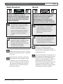
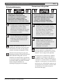
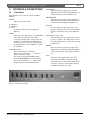
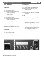
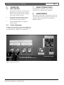
LTC 2821/91
Instruction Manual
EN 21-inch
Color Monitor
LTC 2821/91 | Instruction Manual | Important Safeguards
Important Safeguards
1. Read Instructions - All safety and operating
instructions should be read before the unit is
operated.
2.Retain Instructions - The safety and operating
instructions should be retained for future reference.
3.Heed Warnings - All warnings on the unit and in
the operating instructions should be adhered to.
4.Follow Instructions - All operating and use
instructions should be followed.
5.Cleaning - Unplug the unit from the outlet before
cleaning. Do not use liquid cleaners or aerosol
cleaners. Use a damp cloth for cleaning.
6.Attachments - Do not use attachments not
recommended by the product manufacturer as they
may cause hazards.
7. Water and Moisture - Do not use this unit near
water - for example, in a wet basement, near a
swimming pool, in an unprotected outdoor
installation, or in any area which is classified as a
wet location.
8.Accessories - Do not place this unit on an unstable
stand, tripod, bracket, or mount. The unit may fall,
causing serious injury to a person and serious
damage to the unit. Use only with a stand, tripod,
bracket, or mount recommended by the
manufacturer or sold with the product. Any
mounting of the unit should follow the
manufacturer's instructions and should use a
mounting accessory recommended by the
manufacturer.
An appliance and cart combination should
be moved with care. Quick stops, excessive
force, and uneven surfaces may cause the
appliance and cart combination to overturn.
9.Ventilation - This unit should not be placed in a
built-in installation or rack, unless proper
ventilation is provided, or the manufacturer’s
instructions have been adhered to. The equipment
must not exceed its maximum operating
temperature requirements.
10. Power Sources - This unit should be operated only
from the type of power source indicated on the
marking label. If you are not sure of the type of
power supply you plan to use, consult your dealer
or local power company. For units intended to
operate from battery power or other sources, refer
to the operating instructions.
Bosch Security Systems | November 2003
EN | 2
11. Grounding or Polarization - This unit may be
equipped with a polarized alternating-current line
plug (a plug having one blade wider than the
other). This plug will fit into the power outlet only
one way. This is a safety feature. If you are unable
to insert the plug fully into the outlet, try reversing
the plug. If the plug should still fail to fit, contact
your electrician to replace your obsolete outlet. Do
not defeat the safety purpose of the polarized plug.
Alternately, this unit may be equipped with a 3wire grounding-type plug, a plug having a third
(grounding) pin. This plug will only fit into a
grounding-type power outlet. This is a safety
feature. If you are unable to insert the plug into the
outlet, contact your electrician to replace your
obsolete outlet. Do not defeat the safety purpose of
the grounding-type plug.
12. Power Cord Protection - Power supply cords should
be routed so that they are not likely to be walked on
or pinched by items placed upon or against them,
paying particular attention to cords and plugs,
convenience receptacles, and the point where they
exit from the appliance.
13. Power Lines - An outdoor system should not be
located in the vicinity of overhead power lines or
other electric light or power circuits or where it can
fall into such power lines or circuits. When
installing an outdoor system, extreme care should
be taken to keep from touching such power lines or
circuits as contact with them might be fatal. U.S.A.
models only - refer to the National Electrical Code
Article 820 regarding installation of CATV systems.
14. Overloading - Do not overload outlets and
extension cords as this can result in a risk of fire or
electric shock.
15. Object and Liquid Entry - Never push objects of
any kind into this unit through openings, as they
may touch dangerous voltage points or short out
parts that could result in a fire or electric shock.
Never spill liquid of any kind on the unit.
16. Servicing - Do not attempt to service this unit
yourself as opening or removing covers may expose
you to dangerous voltage or other hazards. Refer all
servicing to qualified service personnel.
EN | 3
LTC 2821/91 | Instruction Manual | FCC Information
17. Damage Requiring Service - Unplug the unit from
the outlet and refer servicing to qualified service
personnel under the following conditions:
a. When the power supply cord or plug is
damaged.
b. If liquid has been spilled or objects have fallen
into the unit.
c. If the unit has been exposed to water and/or
inclement weather (rain, snow, etc.).
d. If the unit does not operate normally by
following the operating instructions. Adjust only
those controls that are covered by the operating
instructions, as an improper adjustment of other
controls may result in damage and will often
require extensive work by a qualified technician
to restore the unit to its normal operation.
e. If the unit has been dropped or the cabinet has
been damaged.
f. When the unit exhibits a distinct change in
performance--this indicates a need for service.
18. Replacement Parts - When replacement parts are
required, be sure the service technician has used
replacement parts specified by the manufacturer
or have the same characteristics as the original
part. Unauthorized substitutions may result in fire,
electric shock, or other hazards.
19. Safety Check - Upon completion of any service or
repairs to this unit, ask the service technician to
perform safety checks to determine that the unit is
in proper operating condition.
20. Coax Grounding - If an outside cable system is
connected to the unit, be sure the cable system is
grounded. U.S.A. models only--Section 810 of the
National Electrical Code, ANSI/NFPA No.70,
provides information with respect to proper
grounding of the mount and supporting structure,
grounding of the coax to a discharge unit, size of
grounding conductors, location of discharge unit,
connection to grounding electrodes, and
requirements for the grounding electrode.
21. Lightning - For added protection of this unit during
a lightning storm, or when it is left unattended and
unused for long periods of time, unplug it from the
wall outlet and disconnect the cable system. This
will prevent damage to the unit due to lightning
and power line surges.
Bosch Security Systems | November 2003
FCC & ICES INFORMATION
(U.S.A. and Canadian Models Only)
This device complies with part 15 of the FCC Rules.
Operation is subject to the following two conditions:
(1) This device may not cause harmful interference,
and
(2) This device must accept any interference
received, including interference that may cause
undesired operation.
NOTE: This equipment has been tested and found to
comply with the limits for a Class A digital device,
pursuant to Part 15 of the FCC Rules and ICES-003 of
Industry Canada. These limits are designed to provide
reasonable protection against harmful interference
when the equipment is operated in a commercial
environment. This equipment generates, uses and
radiates radio frequency energy, and if not installed
and used in accordance with the instruction manual,
may cause harmful interference to radio
communications. Operation of this equipment in a
residential area is likely to cause harmful interference,
in which case the user will be required to correct the
interference at his expense.
Intentional or unintentional changes or modifications,
not expressly approved by the party responsible for
compliance, shall not be made. Any such changes
or modifications could void the user’s authority to
operate the equipment. If necessary, the user should
consult the dealer or an experienced radio/television
technician for corrective action.
WARNING: This is a Class A product. In a domestic
environment, this product may cause radio
interference, in which case, the user may be required
to take adequate measures.
The user may find the following booklet, prepared by
the Federal Communications Commission, helpful:
How to Identify and Resolve Radio-TV Interference
Problems. This booklet is available from the U.S.
Government Printing Office, Washington, DC 20402,
Stock No. 004-000-00345-4.
EN | 4
LTC 2821/91 | Instruction Manual | Safety Precautions
Safety Precautions
CAUTION: TO REDUCE THE RISK OF
ELECTRIC SHOCK, DO NOT REMOVE COVER
(OR BACK). NO USER SERVICEABLE PARTS
INSIDE. REFER SERVICING TO QUALIFIED
SERVICE PERSONNEL.
The lightning flash with an arrowhead
symbol, within an equilateral triangle, is
intended to alert the user to the
presence of uninsulated “dangerous
voltage” within the product’s enclosure
that may be of sufficient magnitude to
constitute a risk of electric shock to
persons.
The exclamation point within an
equilateral triangle is intended to alert
the user to presence of important
operating and maintenance (servicing)
instructions in the literature
accompanying the appliance.
Attention: Installation should be performed by
qualified service personnel only in accordance
with the National Electrical Code or applicable
local codes.
Power Disconnect. Units with or without ONOFF switches have power supplied to the unit
whenever the power cord is inserted into the
power source; however, the unit is operational
only when the ON-OFF switch is in the ON
position. The power cord is the main power
disconnect for all units.
Bosch Security Systems | November 2003
Sécurité
ATTENTION : POUR ÉVITER TOUT RISQUE
D’ÉLECTROCUTION, NE PAS OUVRIR LE
BOÎTIER. IL N’Y A PAS DE PIÈCES
REMPLAÇABLES À L’INTÉRIEUR. POUR
TOUTE INTERVENTION, S’ADRESSER À UN
RÉPARATEUR PROFESSIONNEL COMPÉTENT.
L’éclair fléché dans un triangle équilatéral
avertit l’utilisateur de la présence d’une
« tension dangereuse » non isolée à
l’intérieur de l’appareil et d’une valeur
suffisante pour constituer un risque
d’électrocution.
Le point d’exclamation contenu dans un
triangle équilatéral avertit l’utilisateur de
la présence, dans la documentation qui
accompagne l’appareil, d’importantes
consignes d’utilisation et de maintenance.
Attention : L’installation doit être exclusivement
effectuée par un technicien spécialisé
conformément à la réglementation du code
national de l’électricité des États-Unis (NEC) ou à
la réglementation locale.
Coupure de l’alimentation. Les appareils avec ou
sans commutateur ON-OFF (marche-arrêt) sont
alimentés dès que le cordon d’alimentation est
branché à la source d’alimentation ; toutefois, les
appareils disposant d’un commutateur de
marche-arrêt ne fonctionnent que lorsque celui-ci
est sur la position ON (marche). Le cordon
d’alimentation est l’organe de coupure principal
de l’alimentation pour tous les appareils.
EN | 5
LTC 2821/91 | Instruction Manual | Safety Precautions
Sicherheitshinweise
VORSICHT: DAS GEHÄUSE ZUR
VERMEIDUNG VON ELEKTRISCHEN
SCHLÄGEN NICHT ÖFFNEN. DAS GERÄT
ENTHÄLT KEINE VOM BENUTZER ZU
WARTENDEN TEILE. REPARATUREN NUR
VON FACHPERSONAL AUSFÜHREN LASSEN.
Das Blitzsymbol im gleichseitigen Dreieck
soll den Benutzer auf nicht isolierte
“gefährliche Spannung” im Produkt
hinweisen, die ausreichend stark sein kann,
um die Gefahr von elektrischen Schlägen
für Menschen darzustellen.
Das Ausrufungszeichen im gleichseitigen
Dreieck soll den Benutzer auf wichtige
Bedienungs- und Wartungsanweisungen
in der Dokumentation hinweisen, die
dem Gerät beiliegt.
Achtung: Die Installation darf nur von
qualifiziertem Wartungspersonal gemäß dem
National Electrical Code oder den gültigen
örtlichen Vorschriften durchgeführt werden.
Abtrennen der Spannungsversorgung: Die
Spannungsversorgung zu Geräten mit und ohne
Ein/Aus-Schalter ist hergestellt, wenn das
Netzkabel an eine Netzsteckdose angeschlossen
ist. Das Gerät ist jedoch nur betriebsbereit, wenn
der Ein/Aus-Schalter eingeschaltet ist. Bei allen
Geräten erfolgt das Abtrennen der
Spannungsversorgung über das Netzkabel.
Bosch Security Systems | November 2003
Precauciones de Seguridad
PRECAUCIÓN: PARA REDUCIR EL RIESGO
DE DESCARGA ELÉCTRICA, NO ABRA LAS
TAPAS. EN EL INTERIOR NO HAY NINGÚN
COMPONENTE REPARABLE POR EL
USUARIO. LAS REPARACIONES DEBE
REALIZARLAS PERSONAL CUALIFICADO.
El símbolo de flecha en forma de rayo
situado dentro de un triángulo equilátero
pretende alertar al usuario de la presencia
de “voltaje peligroso” sin aislamiento
dentro de la caja del producto, el cual
podría resultar de una magnitud
suficiente como para presentar un riesgo
de descarga eléctrica para las personas.
El punto de exclamación dentro de un
triángulo equilátero pretende alertar al
usuario de la existencia de instrucciones de
funcionamiento y mantenimiento
(reparación) en la documentación
suministrada con el aparato.
Atención: La instalación debe realizarla
personal cualificado en cumplimiento estricto
del código eléctrico nacional (en el caso de los
EE.UU.) o de los códigos locales aplicables.
Para Desconectar la Alimentación: Unidades
no equipadas con interruptores ON/OFF, son
alimentadas cuando el cable de alimentación es
conectado a la corriente eléctrica. Las unidades
equipadas con interruptores son alimentadas de
igual forma, pero adicionalmente requieren que
el interruptor esté posicionado en ON. El cable
de alimentación es el medio principal de
desconexión del equipo.
EN | 6
LTC 2821/91 | Instruction Manual | Safety Precautions
Veiligheidsmaatregelen
GEVAAR: OPEN DEZE BEHUIZING NIET,
TENEINDE HET RISICO VAN ELEKTRISCHE
SCHOKKEN TE VOORKOMEN. BINNENIN
BEVINDEN ZICH GEEN DOOR DE
GEBRUIKER TE REPAREREN
ONDERDELEN. RAADPLEEG VOOR
REPARATIE GEKWALIFICEERD
SERVICEPERSONEEL.
Het symbool van een bliksem met pijlpunt
in een gelijkzijdige driehoek is bedoeld om
de gebruiker te waarschuwen voor de
aanwezigheid van een niet geïsoleerde
‘gevaarlijke spanning’ binnen in de
behuizing van het product, die voldoende
sterk kan zijn om personen het risico van
een elektrische schok te geven.
Het symbool van een uitroepteken in een
gelijkzijdige driehoek is bedoeld om de
gebruiker te waarschuwen voor de
aanwezigheid van belangrijke bedieningsen onderhouds- (service-) instructies in de
documentatie die met het product zijn
meegeleverd.
Attentie: De installatie dient alleen te worden
uitgevoerd door gekwalificeerd servicepersoneel
en in overeenstemming met de plaatselijk
geldende installatievoorschriften.
Onderbreken van de spanning. Units met of
zonder AAN/UIT-schakelaar, staan onder
spanning zolang het netsnoer is verbonden met
de wandcontactdoos. De unit is echter alleen
bedrijfsklaar als de AAN/UIT-schakelaar in de
AAN-stand staat. Losnemen van het netsnoer is
voor alle units de belangrijkste manier om de
spanning te onderbreken.
Bosch Security Systems | November 2003
Sicurezza
ATTENZIONE: PER RIDURRE IL PERICOLO
DI SCOSSA ELETTRICA, NON APRIRE LE
COPERTURE. L’INTERNO NON CONTIENE
COMPONENTI CHE L’UTENTE PUÒ
RIPARARE PERSONALMENTE. RIVOLGERSI
AL PERSONALE DI ASSISTENZA
QUALIFICATO PER QUALSIASI INTERVENTO
DI RIPARAZIONE..
Il simbolo triangolare di un fulmine con
la punta a freccia intende mettere in
allerta l’utente riguardo alla presenza di
tensioni pericolose non isolate all’interno
del guscio dell’unità, che potrebbero
essere di intensità sufficiente per
costituire pericolo di elettrocuzione.
Il punto esclamativo racchiuso in un
triangolo equilatero intende avvisare
l’utente in merito alla presenza di
importanti istruzioni operative e di
manutenzione nella documentazione di
accompagnamento all’unità.
Precauzione: affidare l’installazione al solo
personale qualificato e nel rispetto del Codice
elettrico nazionale (USA) o dei codici locali
pertinenti.
Scollegamento dell’alimentazione. Gli apparecchi
con o senza commutatori ON-OFF ricevono
corrente tutte le volte che il cavo di
alimentazione è inserito nella presa di forza;
tuttavia, gli apparecchi muniti di commutatore
ON-OFF funzionano solo se quest’ultimo è in
posizione ON. Il cavo di alimentazione serve a
scollegare dalla corrente tutti gli apparecchi.
EN | 7
LTC 2821/91 | Instruction Manual | Safety Precautions
Medidas de Segurança
CUIDADO: PARA REDUZIR O RISCO DE
CHOQUE ELÉCTRICO, NÃO ABRA AS
TAMPAS. O INTERIOR NÃO CONTÉM
PEÇAS QUE NECESSITEM DE
MANUTENÇÃO. A MANUTENÇÃO DEVE
SER EFECTUADA POR PESSOAL DE
ASSISTÊNCIA TÉCNICA QUALIFICADO.
O símbolo do raio com a cabeça de
uma seta dentro de um triângulo
equilátero serve para alertar o utilizar
para a presença de "corrente eléctrica
perigosa" não isolada no interior da
caixa do produto que pode ser
suficiente para dar origem a choques
eléctricos.
O ponto de exclamação dentro de um
triângulo equilátero serve para alertar o
utilizador para a presença de instruções de
funcionamento e manutenção importantes
na documentação fornecida com o aparelho.
Atenção: A instalação deve ser efectuada por
pessoal de assistência técnica qualificado, de
acordo com o National Electrical Code
(Normas de Electricidade Nacionais) ou a
legislação local aplicável.
Desconexão da electricidade. Unidades com
ou sem interruptores ON-OFF são activadas
sempre que o cabo eléctrico for ligado a uma
fonte de alimentação. No entanto, a unidade
fica operacional apenas quando o interruptor
ON-OFF se encontrar na posição ON. Para
desligar a electricidade em qualquer uma das
unidades deve ser utilizado o cabo eléctrico.
Bosch Security Systems | November 2003
Zasady Bezpieczeństwa
UWAGA: ZE WZGLĘDU NA
NIEBEZPIECZEŃSTWO PORAŻENIA
PRĄDEM NIE WOLNO OTWIERAĆ
POKRYWY. W ŚRODKU NIE MA
ŻADNYCH ELEMENTÓW, KTÓRE MOGĄ
BYĆ NAPRAWIANE PRZEZ
UŻYTKOWNIKA. NAPRAWĘ NALEŻY
POWIERZYĆ AUTORYZOWANEMU
PUNKTOWI SERWISOWEMU.
Błyskawica ze strzałką wewnątrz trójkąta
równobocznego ma za zadanie zwrócić uwagę
użytkownika na obecność nieizolowanego
"niebezpiecznego napięcia" wewnątrz obudowy
urządzenia, o wielkości stwarzającej
niebezpieczeństwo porażenia prądem.
Wykrzyknik wewnątrz trójkąta równobocznego
ma za zadanie zwrócić uwagę użytkownika na
ważne czynności, związane z obsługą i
konserwacją urządzenia, zamieszczone w
Instrukcji obsługi.
Uwaga: Instalację urządzenia powinien wykonać tylko
wykwalifikowany personel, zgodnie z przepisami NEC
lub odpowiednimi przepisami miejscowymi.
Odłączanie zasilania. Urządzenia zarówno nie
posiadające, jak i posiadające wyłączniki ON-OFF
znajdują się pod napięciem, jeżeli tylko przewód
zasilający jest połączony ze źródłem zasilania. Jednakże
urządzenie działa tylko wtedy, gdy wyłącznik znajduje
się w położeniu ON. Przewód zasilający jest głównym
odłącznikiem zasilania dla wszystkich rodzajów
urządzeń.
EN | 8
LTC 2821/91 | Instruction Manual | Contents
Table of Contents
Important Safeguards . . . . . . . . . . . . . . . . . . . . . . . . . . . . . . . . . . . . . . . . . . . . . . . . . . . . . . . . . . . . . . . . . .2
FCC Information . . . . . . . . . . . . . . . . . . . . . . . . . . . . . . . . . . . . . . . . . . . . . . . . . . . . . . . . . . . . . . . . . . . . .3
1
UNPACKING . . . . . . . . . . . . . . . . . . . . . . . . . . . . . . . . . . . . . . . . . . . . . . . . . . . . . . . . . . . . . . . . .8
2
SERVICE . . . . . . . . . . . . . . . . . . . . . . . . . . . . . . . . . . . . . . . . . . . . . . . . . . . . . . . . . . . . . . . . . . . . .8
3
DESCRIPTION . . . . . . . . . . . . . . . . . . . . . . . . . . . . . . . . . . . . . . . . . . . . . . . . . . . . . . . . . . . . . . . .8
4
INSTALLATION . . . . . . . . . . . . . . . . . . . . . . . . . . . . . . . . . . . . . . . . . . . . . . . . . . . . . . . . . . . . . . .8
4.1
Power . . . . . . . . . . . . . . . . . . . . . . . . . . . . . . . . . . . . . . . . . . . . . . . . . . . . . . . . . . . . . . . . . . . . . . . .8
4.2
Mounting . . . . . . . . . . . . . . . . . . . . . . . . . . . . . . . . . . . . . . . . . . . . . . . . . . . . . . . . . . . . . . . . . . . . . .8
4.3
Cover Removal . . . . . . . . . . . . . . . . . . . . . . . . . . . . . . . . . . . . . . . . . . . . . . . . . . . . . . . . . . . . . . . . .8
5
CONTROLS & CONNECTIONS . . . . . . . . . . . . . . . . . . . . . . . . . . . . . . . . . . . . . . . . . . . . . . . . . .9
5.1
Front Panel . . . . . . . . . . . . . . . . . . . . . . . . . . . . . . . . . . . . . . . . . . . . . . . . . . . . . . . . . . . . . . . . . . . .9
5.2
Rear Panel . . . . . . . . . . . . . . . . . . . . . . . . . . . . . . . . . . . . . . . . . . . . . . . . . . . . . . . . . . . . . . . . . . .10
6
OPERATION . . . . . . . . . . . . . . . . . . . . . . . . . . . . . . . . . . . . . . . . . . . . . . . . . . . . . . . . . . . . . . . . .11
6.1
Basic Operation . . . . . . . . . . . . . . . . . . . . . . . . . . . . . . . . . . . . . . . . . . . . . . . . . . . . . . . . . . . . . . . .11
6.2
Picture Adjustment . . . . . . . . . . . . . . . . . . . . . . . . . . . . . . . . . . . . . . . . . . . . . . . . . . . . . . . . . . . . . .11
7
BASIC CONNECTIONS . . . . . . . . . . . . . . . . . . . . . . . . . . . . . . . . . . . . . . . . . . . . . . . . . . . . . . . .11
8
1
MAINTENANCE . . . . . . . . . . . . . . . . . . . . . . . . . . . . . . . . . . . . . . . . . . . . . . . . . . . . . . . . . . . . . .11
UNPACKING
Unpack carefully. This electronic equipment should be
handled carefully.
Check to ensure that the following items are included
for the model number of the unit ordered.
Verify the model number.
Service Centers
U.S.A.: Phone: 800-366-2283 or 408-956-3895
fax:
800-366-1329 or 408-956-3896
e-mail:
[email protected]
Canada:
514-738-2434
Europe, Middle East & Asia Pacific Region:
32-1-440-0711
For additional information,
see www.boschsecuritysystems.com.
Power cord, 3-wire with grounded U.S. type plug.
Power cord, 3-wire with grounded European
Continental type plug.
Instruction Manual.
If an item appears to have been damaged in shipment,
replace it properly in its carton and notify the shipper.
If any items are missing, notify your Bosch Security
Systems, Inc. Sales Representative or Customer Service
Representative.The shipping carton is the safest
container in which the unit may be transported. Save it
for possible future use.
3
DESCRIPTION
The LTC 2821/91 is a 51-cm (20-inch) high resolution
color monitor. It is attractively styled and accepts both
NTSC and PAL formats.
4
INSTALLATION
4.1
Power
The LTC 2821/91 operates from 90 to 260 VAC, 50/60
Hz power sources. Power consumption is 90 watts.
4.2
Mounting
This unit is supplied as a desktop unit.
2
SERVICE
4.3
If the unit ever needs repair service, the customer
should contact the nearest Bosch Security Systems, Inc.
Service Center for authorization to return and shipping
instructions.
Bosch Security Systems | November 2003
Cover Removal
Removal of the cover, and adjustment of
internal controls, should only be performed by
qualified service personnel. Not userserviceable.
EN | 9
LTC 2821/91 | Instruction Manual | Controls & Connections
5
5.1
CONTROLS & CONNECTIONS
Front Panel
See FIGURE 1 for location of controls and LED
Indicator.
POWER
Selects power ON or OFF.
R: VIDEO A
G: VIDEO B
O: VCR
Combination Red, Green, Orange LED
Indicator.
VIDEO
Selects the video signal inputs to the VIDEO A
and VIDEO B (composite video BNC
connectors) and the audio signal inputs to the
AUDIO A and AUDIO B terminals (RCA
connectors) on the rear panel. When selected,
the LED indicates red for VIDEO A or green
for VIDEO B.
VOLUME/DATA
These buttons have two functions:
Volume control: Press the or buttons to
adjust the speaker volume.
Data controls: When the SHARP, TINT,
COLOR, BRIGHTNESS or CONTRAST
buttons are pressed, the or buttons will
change the level of the selected function.
Figure 1: Location of Controls
Bosch Security Systems | November 2003
CONTRAST
Press this button to adjust picture contrast.
Adjust the level with the VOLUME buttons to
control the image contrast (Default is 60).
BRIGHTNESS
Press this button to adjust picture brightness.
Adjust the level with the VOLUME buttons to
control the image brightness (Default is 50).
COLOR
Press this button to adjust the picture color
intensity. Adjust the level with the VOLUME
buttons to control the image color (Default is
50).
TINT (NTSC format only)
Press this button to control the picture color to
be close to natural color. Adjust the level with
the VOLUME buttons to control the color tint
(Default is 50).
SHARP
Press this button to adjust the picture image.
Adjust the level using the VOLUME buttons to
control the sharpness of the image (Default is
50).
VCR
Selects the video signal input to the VCR
(composite video BNC connector) and the
audio signal input to the VCR terminal (RCA
connector) on the rear panel. When selected,
the LED will indicate in orange.
EN | 10
LTC 2821/91 | Instruction Manual | Controls & Connections
5.2
Rear Panel
AUDIO B IN/OUT
See FIGURE 2 for location of rear panel connectors.
IN: Audio signal input terminal.
VIDEO LINE
OUT: Loop-through video signal output terminal.
VIDEO A IN/OUT
NOTE: For corresponding video signal, use the
VIDEO B terminals .
IN: Video signal input terminal.
OUT: Passive loop-through video signal output
terminal (auto termination).
NOTE: For corresponding audio signal, use the
AUDIO A terminals.
VIDEO B IN/OUT
IN: Video signal input terminal.
OUT: Passive loop-through video signal output
terminal (auto termination).
NOTE: For corresponding audio signal, use the
AUDIO B terminals.
VCR IN: Video signal input terminal.
NOTE: For corresponding audio signal, use the
AUDIO IN VCR terminal.
AUDIO LINE
AUDIO A IN/OUT
IN: Audio signal input terminal.
OUT: Loop-through audio signal output terminal.
NOTE: For corresponding video signal, use the
VIDEO A terminals.
Figure 2: Location of Rear Connectors
Bosch Security Systems | November 2003
AUDIO IN VCR: Audio signal input terminal.
NOTE: For corresponding video signal, use the VCR
IN terminal .
AC IN
Power input connector. Connects the supplied
AC power cord to the appropriate AC outlet.
NOTE:
The impedance is automatically set to 75 ohms
by the input of a signal on the input connector
while operating in a single connection mode.
However, if a cable is connected to the output
connector, the connection is placed into the
open status by the multiple connection and
high impedance automatically selected. Do not
leave an unused cable connected to the
monitor. If a single cable is used, then it must
be connected to the input connector for the 75
ohms auto termination selector to function
properly.
EN | 11
LTC 2821/91 | Instruction Manual | Operation
6
OPERATION
7
6.1
Basic Operation
The illustration in FIGURE 3 shows the basic
connections for composite video equipment.
1.
Press the Power switch to turn on the power.
When the power is ON, the video selector
indicator is lit. When the power is OFF, the
video selector indicator is unlit.
2.
Press (toggle) the Video button to choose
VIDEO A or B. Press the VCR button to
choose video from the VCR input.
3.
Press the VOLUME button to adjust the
speaker volume.
6.2
8
BASIC CONNECTIONS
MAINTENANCE
If the quality of the picture on the monitor is poor and
cannot be improved, check all system connections and
cable runs. Service should only be performed by a
qualified technician.
Picture Adjustment
To adjust the picture's Sharp, Tint, Color, Brightness or
Contrast, press the appropriate button then adjust with
the Volume button. Default for each setting is 50.
From Video
Source
To Loop-through Device
(e.g., Video Recorder, Monitor, etc.)
Figure 3: Basic Connections
Bosch Security Systems | November 2003
From Output of VCR
Bosch Security Systems, Inc.
850 Greenfield Road
Lancaster, PA 17601 EE.UU.
Tel: 800-326-3270
Fax: 1-717-735-6560
www.boschsecuritysystems.com
Robert Bosch GmbH
Geschäftsbereich
Postfach 10 60 50
70049 Stuttgart
Telefax (0711) 8 11-12 34
Bosch Security Systems B.V.
P.O. Box 80002
5600 JB Eindhoven
The Netherlands
Tele +31 40 27 80000
© 2003 Bosch Security Systems GmbH
3935 890 47211 03-47 | Updated November 17, 2003 | Data subject to change without notice.
Part No.: AA68-03240A-01
Printed in Korea