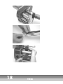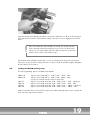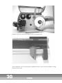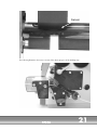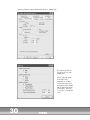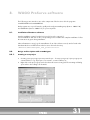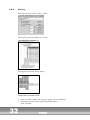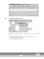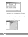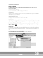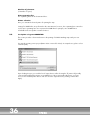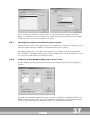
1
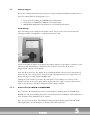
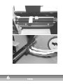
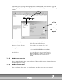
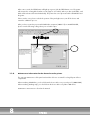
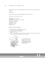
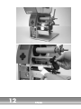
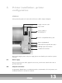
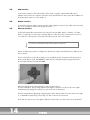
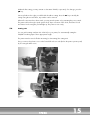
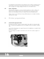
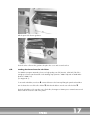
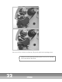
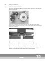
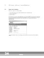
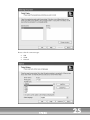
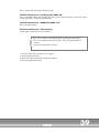
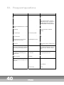
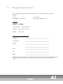
Manual TP298
List of Contents
1. Useful start-up information
4
1.1. Start-up support
5
2. General information / product description
9
2.1. General information
2.2. Product description
9
9
3. Safety information
10
3.1. General information
3.2. Properties of the thermal print head
10
10
4. Scope of delivery
11
5. Printer installation - printer configuration
13
5.1.
5.2.
5.3.
5.4.
5.5.
5.6.
5.7.
Power supply
Computer connections
USB interface
RS-232 interface
Ethernet interface
Cutting unit
Printer configuration
13
13
14
14
14
15
16
6. Printer preparation
16
6.1.
6.2.
6.3.
6.4.
16
17
19
23
Insertion of the appropriate roller
Loading the thermal transfer ink ribbon
Loading the WAGO marking strips
Loading the WMB Inline
7. Printer driver installation
24
7.1. Printer driver installation
7.2. Printer driver settings for marking strips
7.3. Printer driver settings for WMB Inline
24
27
28
8. WAGO ProServe software
31
8.1. Installation of ProServe software
8.2. Design and inscription with smartDesigner
8.3. Inscription using smartMARKING
31
31
36
9. Printer maintenance
38
9.1.
9.2.
9.3.
9.4.
38
38
38
38
General
General cleaning
Cleaning the print roller
Cleaning the print head
10. Frequent questions
40
11. Registration form
41
1.
Useful start-up information
Dear customer,
We are happy about your decision to utilize the WAGO thermal transfer printer TP298.
In addition to this manual, you receive a device that is preset for the WAGO "marking strips"
(Art.-No. 2009-0110) and "WMB Inline" (Art. No. 2009-0115).
In order to simplify the start of these new marking techniques, we offer the following support options:
1. Start-up support and registration form
2. Manual TP298
3. WAGO ProServe 4.1 - CD
4. Telephone and e-mail service
Technical Support ProServe
WAGO Kontakttechnik GmbH & Co. KG
Hansastraße 27 · D-32423 Minden
Phone:
+49 571/887-630
Fax:
+49 571/887-8630
Email:
[email protected]
Internet: http//www.wago.com
You can contact us
Monday through Thursday 8:00AM - 5:00PM
Friday
8:00AM - 3:00PM
During all other times please leave us a message - we will call back as soon as possible!
Please use this option, if you have questions regarding the ProServe software or the TP298 thermal
transfer printer. We will gladly put our know-how at your disposal.
We wish you joy and success with your WAGO inscription products!
4
TP298
1.1.
Start-up support
This section contains information required by you to begin working with WAGO inscription devices.
We have summarized the following data for you:
Preset values for marking strip 2009-0110 in smartDesigner
Preset values for WMB Inline 2009-0115 in smartDesigner
IMPORTANT: Maintenance information for your thermal transfer printer
Local Settings
The local settings can be changed in the printer's menu. This procedure is shown in detail in the
following example of changing the country from Germany to USA.
First press the "Menue" button on the printer. "Kurzstatus" appears on the display. Click twice on the
right arrow until "Einstellungen" is displayed, followed by one click on the down arrow.
"Regionaleinst." appears on the display.
Now click the down arrow. The display shows "Land-Deutschland". Then press the centre button of
the arrow pad. Your country can be selected using the left/right arrow keys (e.g. USA). Once you
have selected your country, click the ENTER button.
Clicking the up arrow takes you back to the main folder. "Local settings" is now shown on the
display. Press the up arrow key again and the display will show "Setup". Press the left arrow three
times to close the menu. "Ready" is displayed and the setting is complete.
1.1.1.
Preset values for WAGO smartDESIGNER
Prior to delivery, the TP298 printer was preset specifically for "marking strips" and "WMB Inline".
BEFORE you may print a marking strip, please note the printer driver installation in this manual and a
short description of the WAGO ProServe software.
Here you can see the position of the WAGO inscription products marking strips (left) and WMB
Inline (right). Please do not attempt to use both products at the same time!
TP298
5
6
TP298
Immediately prior to printing a marking strip from the smartDESIGNER, we would like to suggest the
following settings that have been tested by WAGO. In smartDESGNER, please activate the following
settings:
1.1.2.
Distance to left edge:
the set position is located left to the
roller cut-out as seen from the front!
Distance of text to left edge:
please reduce this setting to at least "2".
Printing factor:
please correct the value shown above once
in your smartDESIGNER after new installation.
Stretch factor:
this factor only serves as a correction factor for
different lengths of the terminal strips produced.
Please note the detailed description in your
manual.
WMB Inline preparation
Prior to printing the WMB Inline, please take note of the manual's description of material handling
and print light sensor settings.
1.1.3.
WMB Inline calibration
Upon completion of these steps, you start the printer and tilt the print head lever downward.
TP298
7
After some seconds, the FEED button will light up in green. Push the FEED button once. The printer
will measure the existing labels within seconds (approx. 6-7 labels). When you then push FEED, each
label will be advanced forward individually. The printer has correctly measured the WMB label and
the gutter.
If this is not the case, please recheck the position of the print light sensor, turn off the device and
restart the calibration process.
After you have created a project with WMB Inline inscription (2009-115) in smartDESIGNER,
please note the following setting values prior to label output:
1.1.4.
Maintenance information for the thermal transfer printer
The ongoing maintenance of the print head and the roller are essential for a long lifespan of these
components.
When inscribing WMB Inline, you should clean the device after every second spool (3,000 WMB).
When inscribing marking strips, you should clean the device after every 50 to 100 meters.
Maintenance instructions are found in the manual.
8
TP298
2.
General information / product
description
2.1.
General information
By purchasing the innovative WAGO inscription system you have adopted the most cost-effective
solution for terminal block labeling.
®
®
The new TOPJOB S terminal blocks with CAGE CLAMP S connection by WAGO offer new solutions
in cost reduction in terminal block labeling. The center ceptacles for all terminal blocks with sizes
from 1.5 mm² to 6 mm² and from 10 mm² to 16 mm² are aligned to the same level. This is a
prerequisite for marking using a full length marking strip for terminal blocks of different diameters.
The cost saving solution: The marking sequence assigned to the terminal block width can be
automatically generated when creating the terminal block configuration using the WAGO
smartDesigner program. Using these data, the marking strip is printed directly from a thermal transfer
printer.
For terminal blocks with conductor cross-sections of 2.5 mm² to 95 mm², an additional label
inscription on spools, WAGO WMB Inline, with 1,500 labels or 8,000 labels per spool is offered
for printing using the same thermal transfer printer. The label mounting is simple, easy and costeffective - one touch is enough.
The WMB Inline labels can be stretched from 5 to 5.2 mm, which means they can be attached to all
2.5mm² terminal blocks without singularization. In addition, they can be separated simply by turning
them and then applying them individually to all rail-mounted terminal blocks.
Please observe all information in respect to the admissible print media and the notes on device
maintenance, in order to avoid damages and premature wear and tear on your printer.
2.2.
Product description
For printing on WAGO inscription materials, standard label printers are used after simple
modifications. The TP298 printer is a label printer to be utilized either in direct thermal or in thermal
transfer print, providing a nearly unlimited variety in the graphical design. The cast aluminum
assembly enclosure assures optimum functional safety even in harsh conditions.
The integration of a 32Bit Motorola processor and a generously designed user memory of 8 MB
provide print-outs in seconds.
The integration of a variable voltage power supply unit makes it unnecessary for the operator to
adjust the printer to different system voltages. The modular design assures a quick and efficient
service. As accessories to the TP298, an external winder and a cutting knife are available.
TP298
9
3.
Safety information
3.1.
General information
ATTENTION!
•
•
•
•
•
•
•
•
This device may be used exclusively for the inscription of labels, endless paper and similar
materials, and WAGO inscription materials.
Connect the device using a power supply with suitable voltage. The device is designed for AC
voltages between 100 and 240 volt. Connect the device using a plug with a PE terminal!
The printer may be interfaced only to devices under protective extra-low voltages!
Please assure that all devices to be interfaced (printer, computer, etc.) are turned off at the time
of connection! The devices must also be turned off when the connections are to be interrupted.
Please assure that the printer is protected from wetness!
It is possible to operate the printer when the cover is open. In this state, rotating parts are
accessible. Please assure that hair, jewelry or similar items will not be touched by those parts!
The print head module may heat up during the printing process. Touch with caution!
Do not perform any manipulations on the device beyond those described in the instruction
manual! If you need to remove the safety labels to change settings, please contact WAGO
support.
CAUTION! Do not open the back cover! Life-threatening voltages!
3.2.
Properties of the thermal print head
ATTENTION!
The thermal print head is the most sensitive part of your printer. You must observe the following:
•
•
•
•
•
The protective glass layer on the print head must not be touched by your hand. Do not use sharp
objects (knife, screwdriver etc.) when cleaning the print head.
Always assure during the print process that the inscription material is free of dirt and that dirt
cannot be pulled under the print head. This may damage the head.
Assure a proper and smooth inscription surface. Rough surfaces act like emery paper and
reduce the print head's life span.
Clean the head regularly (see chapter 8).
Print at the lowest possible head temperature.
Your print head can easily be damaged when handled inappropriately. In such cases, your warranty
claim is forfeited.
10
TP298
4.
Scope of delivery
Please verify the printer condition immediately after its arrival to determine any possible transport
damages.
ATTENTION!
Please keep the original transport packaging for possible future transports.
The standard scope of delivery comprises:
Thermal transfer printer TP298
Power cable
3m USB cable and 3m RS-232 interface cable
2 empty foil cores 100 mm
2 empty foil cores 35 mm
Operating instructions
WAGO ProServe CD
Registration form
REMOVAL OF TRANSPORT BLOCKS
Lift label printer by its retaining loops from the box.
Inspect the printer for transport damages.
Position the printer on a level surface.
Open the cover. (1)
Remove the transport block (foam pads) above and below the print head. Turn the side print
head lever to remove the foam pads more easily. (2)
Please retain the foam pads
together with the original
packaging, because, in case
of future transports, the print
head should be secured as
described above.
TP298
11
12
TP298
5.
Printer installation - printer
configuration
ATTENTION!
Never position the printer in a location where the device could be subject to dampness.
Supply connection socket
Power switch
Slot for Cardbus or
PC Card Type II
Slot for CompactFlash memory card
Ethernet 10/100 Base-T
USB interface for keyboard and scanner
USB-High Speed slave interface
Serial RS-232 C interface
Prior to connecting the printer to the power supply, please assure that the power switch is in position
"0" (OFF).
5.1.
Power supply
Plug one end of the power cable, supplied as an accessory, into the device and the other end to a
grounded wall outlet.
5.2.
Computer connections
As standard, the TP298 features a serial RS-232 interface, an USB interface for local operation, and
an Ethernet interface for connection to a network.
TP298
13
5.3.
USB interface
Connect the computer to the USB interface of the printer, using the supplied A-B cable. Upon
initiation of the printer, the computer detects the newly installed device and requests the installation of
the printer driver. Please see also chapter 7.
5.4.
RS-232 interface
5.5.
Connect the computer and the printer using the cable supplied, and secure the cable connection with
the screws and clips located on the plug-in connectors.
Ethernet interface
Connect the printer Ethernet interface to the network, using an RJ45 cable for 10 base T or 100
base T, respectively. You will require a patch cable for connection to the network jack, and a crossover cable for a direct printer connection to the Ethernet card of a local computer.
You must use a shielded cable for the printer connection!
At time of delivery, the printer is configured to obtain an IP address via DHCP from a suitable device
in the network.
If your network does not provide a DHCP server, the DHCP must be deactivated. The printer has a
factory-set IP address (192.168.000.077) which may be changed using the navigator pad. The
preset Subnet Mask is 255.255.255.000.
When the display shows "Bereit" [Ready], click on button "Menu".
The term "Kurzstatus“ [Short State] appears in the display. Click twice on the arrow to the right to
"Einstellungen" [Settings], followed by one click on the arrow downward.
The term "Regionaleinst" [Regional settings] appears in the display. Click 3x on the arrow to the right
to "Schnittstellen" [Interfaces], followed by one click on the arrow downward.
Then click 4x on the arrow to the right to "Ethernet“, followed by one click on the arrow downward.
14
TP298
Within the first setting, you may activate or deactivate "DHCP", respectively. For changes, press the
key.
One step further to the right, you will find the IP address setting. Press the
setting. Using the arrow buttons, any number can be entered.
key to modify the
When all connections have been made, you may turn the printer on by actuating the power switch.
The printer will run through a quick system check. Upon execution of the check, the button "Feed"
and "Menu" in the navigator pad will light up. The printer is now ready.
5.6.
Cutting unit
You can add a cutting unit (Item No. 258-161) to your printer, for automatically cutting the
®
TOPJOB S marking strips to their appropriate length.
The printer must be turned off when mounting (or demounting) the cutting unit!
First, you remove the plastic cover on the frontal left enclosure side (below the printer operator pad)
by loosening the Allen screw.
TP298
15
The cutting blade is provided with two longer guiding pins on the rear. Make sure that these pins are
seated in the bores of the printer enclosure. Then press the whole unit - possibly without jamming with some slight pressure. Finally, hand-tighten the thumb screw on the knife front side.
5.7.
Printer configuration
During the printer configuration, you may set a number of parameters, in order to configure your
printer for the actual application situation. The internal parameters for regional, device, print,
interface and security settings are factory-set to satisfy the requirements of WAGO products.
Changes, as they are required for the processing of different print jobs, can usually be realized by
adjusting software settings.
6.
Printer preparation
6.1.
Insertion of the appropriate roller
The thermal transfer printer is supplied as standard with the roller suitable for inscribing the WMB
Inline. You may also print marking strips for the series TOPJOB®S and for series 870 etc., using this
roller.
A print roller for label printing is also supplied. The print roller for WMB Inline is not suitable for label
printing, due to its profile.
The roller exchange is very simple. Loosen the three screws on the side cover plate, using the tool
supplied.
16
TP298
Pull the print roller from its guidance.
Slide the other roller into the guidance. Replace the cover and screw it back on.
6.2.
Loading the thermal transfer ink ribbon
For WAGO inscription materials, please use high-quality resin foil (Item No. 258-145). This foil is
smudge-proof and scratch-resistant on the marking strips (Item No. 2009-110) and on WMB Inline
(Item No. 2009-115)
(see Appendix 1)
To insert the ink ribbon, turn lever 4 counterclockwise to the limit stop lifting the print head and then
turn clockwise the nut of the roller holder 3. Slide the ink ribbon onto the rear roller holder 2.
Slide the ink ribbon so far onto the rear roller holder, that approx. 20mm space remains between ink
ribbon and the enclosure wall of the printer.
TP298
17
18
TP298
Fixate the ink ribbon by attaching an adhesive strip to the cardboard core 1 on the front transport
roller and turn the front roller somewhat into transport direction in order to slightly tension the ink
ribbon.
Please note which side of the ink ribbon is coated. The coated side must
not face the print head when inserting it. If you are not sure which side is
coated, you can test the ribbon with some adhesive tape: the coated side
will leave some residue on the adhesive tape.
The thermal transfer ink ribbon and the foil cores are now fixated to the front and rear transport
rollers by a counter-clockwise turning of the nuts. For this you hold the ink ribbon tightly, and tighten
the nuts until you feel resistance.
6.3.
Loading the WAGO marking strips
The following marking strips are available from WAGO:
2009-110
2009-130
709-177
709-178
709-187
709-188
Strips for Series TOP JOB®S – width 11 mm – 50 m – white
Strips for Series TOP JOB®S – width 11 mm – 300 m – white
(requires an external unwinder, Item No. 258-169)
Strips for Series 870, 869, 862, 270 – width 7.5 mm – 50 m – translucent
Strips for Series 870, 869, 862, 270 – width 7.5 mm – 50 m – white
Strips for Series 870, 869, 862, 270 – width 7.5 mm – 300 m – translucent
Strips for Series 870, 869, 862, 270 – width 7.5 mm – 300 m – white
Make sure that the device is turned off. Insert the spool with the marking strip in such a way, that the
inner side of the strips will be inscribed.
TP298
19
Guide the strip above the pin and between the two strip guide rails.
Then re-adjust the sensor. The strip must be guided between the sensor fork, the ink ribbon is laying
above the sensor fork.
20
TP298
Sensor
The following illustration shows an overview of the whole progress of the marking strip.
TP298
21
Now move the lever clockwise to its limit stop. This puts the print head in its printing position.
Always loosen the print head, when the printer is not in use for some time.
This avoids abrasion and defects.
22
TP298
6.4.
Loading the WMB Inline
Make sure that the device is turned off.
The insertion of the WMB Inline (2009-115) is performed analog to the insertion of the marking strip.
Please note the following:
The spool must be inserted in such a manner that the upper side of the labels is printed and the
follow-up guidance of the labels is assured. The spool, the red strip guidance and the material should
be aligned to a straight line.
Sensor alignment:
The sensor should be aligned to the left edge of the label,
not centered to the label strip.
Verify the correct setting by turning the printer on and waiting until the FEED button lights up. Now
press once on FEED. 8 labels will be pulled forward (calibration length). If, upon each FEED
actuation, only one label is pulled forward, then the printer is ready for operation.
TP298
23
7.
Printer driver installation
7.1.
Printer driver installation
There are 3 options to control the TP298:
1. via the USB interface (not possible with Windows NT or Windows 98)
2. via the serial interface
3. via the network
The printer drivers are part of the WAGO ProServe CD. The installation is performed in Setup using
the register "Downloads". Insert the CD into the CD-Rom drive. If the auto start function is activated,
the menu will start automatically. If the auto start function is not activated, click on the file
proserve.exe.
Select the valid printer and your operating system and follow the instructions of the installation
routine.
24
TP298
Please select the connection type:
USB
COM
Network
TP298
25
The status monitor is not mandatory for the driver operation and may be installed when required.
The installation of the printer driver is completed.
26
TP298
7.2.
Printer driver settings for marking strips
In the Windows Printers folder, rightclick on the corresponding printer
(TP298) and select the entry "Printer
setting" in the context menu.
The settings for print speed, print
temperature and paper format can
be set under Options. The illustration
shows the optimum values for
marking strips (Item No. 2009-110):
The settings for the sensor and for the
cutting unit can be modified in
Advanced printer settings. The
following illustration shows the
recommended settings for the
inscription of marking strips (Item No.
2009-110).
TP298
27
These settings have been tested for the application of a cutting knife (Item No. 258-161). If you do
not use a cutting knife, please activate in item Cutting the parameter NEVER.
The cutting offset is usually in the range between –1.0 mm and –1.8 mm, depending on the print
head position. Please determine the appropriate offset by conducting test prints. Cutting offset 2 is
usually set to 0 mm.
7.3.
Printer driver settings for WMB Inline
The settings for the print on WMB Inline (2009-115) are shown below, analog to the recommended
settings for marking strip print.
If the ink ribbon begins to tear or shows severe fraying at an early state of
the printing process, the print temperature needs to be lowered.
28
TP298
TP298
29
Advanced printer settings WMB Inline (Item no. 2009-115):
The print head offset is
preset for the use with
WMB Inline.
Please adjust the print
head offset only
minimally (in 1/10th
increments upwards) if
the imprint on the WMB
labels shifts horizontally
downwards. This may
occur after a certain time
of use.
30
TP298
8.
WAGO ProServe software
The following section introduces two other components of the ProServe CD: the programs
smartDESIGNER and smartMARKING.
Both programs are very well suited to quickly and easily print marking strips (Item no. 2009-110)
and WMB Inline (Item no. 2009-115) on your new printer.
8.1.
Installation of ProServe software
Start the installation routine from the ProServe CD (see also section 6.1).
Select "Installation" and click on the corresponding icons to initialize the complete installation. Follow
the instructions as given during installation.
Other information to setup (e.g. the uninstallation of an older software version) can be found in the
Quickstart brochure in PDF format on the ProServe CD in the directory
\Manuals\SmartDesigner_and_productLocator.
8.2.
Design and inscription with smartDesigner
8.2.1.
Creating a new project
•
•
Creating a new project group in menu item Project – "Insert project group". A project group is a
common folder for e.g. all projects of a customer, a control cabinet, etc.
Right click on the project group and select the item Insert mounting rail. The mounting rail dialog
opens where other settings can be made.
TP298
31
8.2.2.
Planning
Direct input of article number - click on "ADD"
Via Drag & Drop from the library tree / index
Via Drag & Drop from the library display
INSERT ARTICLE SEVERAL TIMES
•
•
32
Input of an article number and change of quantity - click on "Planning"
Via Drag & Drop from library display by holding shift key.
Input of quantity.
TP298
8.2.3.
Inscription of planned terminal blocks
First deactivate the item Activation of font size check > Limitation of fonts in the menu item Options >
Settings.
•
•
•
•
Section of the inscription surfaces (multiple selection possible using Shift or Ctrl).
Click on button Inscription table or
Select menu item Inscription - Inscription table
Selection of marking strip or WMB Inline
TP298
33
•
•
8.2.4.
Either direct input of inscriptions in the table, or selection of cells of the inscription table and
inscription using the Wizard.
Output of inscription via menu item "Inscription - Print marking strip" or "Inscription - print WMB
Inline".
Settings in smartDesigner
To obtain optimum print results on the marking strips or WMB Inline, please make the following
settings in the software.
Settings for the inscription of marking strips 2009-110 as follows:
Please select menu item "Options" > "Settings".
The following formatting parameters can be set in the area "Strip print":
34
TP298
DESCRIPTION OF PARAMETERS
Distance to left edge
The distance to the left edge is variable and depends on the position of the strip in the device
(between 5 and 80 mm).
Text Distance from left edge
The preset standard value does not usually require modification.
Line thickness
Grid lines are the separating lines between the individual terminal block inscriptions. Their thickness
value should not be larger than 0.5.
Separating line thickness
The thickness of the lines at the end of a strip (= cutting edge).
Stretch factor
If you are planning 100 terminal blocks with a width of 5 mm next to each other, you theoretically
require a strip with a length of 50 cm. In reality however, the terminal block may be a bit longer and
you require a strip with a length of e.g. 50.2 cm. This is quite normal, because small gaps may occur
between the individual terminal blocks.
The stretch factor results from: true strip length / theoretical strip length. Using the above example:
50.2 cm / 50 cm = 1.004
Printer factor
For each printer, the printer factor is determined by the factory prior to delivery. The value for your
printer is found in the attached "Important Information". This value should not be changed at a later
date.
Use of TrueType fonts in smartDESIGNER
Please deactivate the following options in "Options > Settings > Inscription":
TP298
35
Number of print-outs
(= Number of copies)
Print separating line
The separating lines can be deactivated here.
Printer selection
Here you activate the desired printer for printing the strip.
Settings for WMB Inline are performed in the same manner, however, the separating lines cannot be
set, because separating lines are not printed in WMB Inline in principle, since WMB Inline is
stretchable and can equalize certain tolerances.
8.3.
Inscription using smartMARKING
This section provides a short introduction to the printing of WAGO marking strips with your new
TP298.
You start by creating a new project (Button New or menu File >New). As output device, please select
TT Printer (Roll).
Upon clicking Accept you reach the list of output devices after selecting the TT printer. All possibly
connected thermal transfer printers are available here. Upon opening the tab Printer you have
access to the installed printer drivers and can select the output device by clicking on the button
Apply.
36
TP298
First, you click on the tab "Printer" and select the corresponding driver by clicking on the button
Apply . You switch then to the area Output devices and select the desired output device. By clicking
on the button Close you leave the output devices dialog.
8.3.1.
Selecting the inscription material for TT printer or plotter
Subsequent to the selection of the printer driver or the output device respectively, a dialog box opens
with all inscription materials available for the thermal transfer printer or plotter.
The WAGO marking strip 11 mm has been designed for the inscription of the new terminal block
©
series TOPJOB S. The WAGO marking strip 7.5 mm is suitable for the series 870, 270, 869, as well
as for the motor terminal blocks 281-530 to 281-532.
8.3.2.
Creating a grid for WAGO marking strips 7.5 and 11 mm
By right clicking on the strip and selection of the menu item "Divide strip", the following dialog box
appears:
©
The width of the individual terminal blocks (e.g. 5.2 mm for a TOPJOB S terminal block of the Series
2002), and their quantity can be entered. The remaining residual length is calculated automatically,
in order to generate a strip with a maximum length of 1m, with different grid divisions.
TP298
37
9.
Printer maintenance
9.1.
General
The printer requires little maintenance.
A regular cleaning of the print head is very important. Only this assures a consistently good print
image and contributes considerably to the prevention of premature wear and tear of the print head.
Attention!
The printer must be disconnected from the power supply prior to maintenance activities!
We recommend the following maintenance tools:
•
•
•
9.2.
Solvent 50 (strong adhesive label solvent) or
undiluted alcohol (spirit)
a soft, lint-free cloth or cotton swabs
General cleaning
During operation, dust particles will collect, especially in the area of the printing mechanism. Remove
these particles with a soft brush or compressed air.
The external surfaces of the printer may be cleaned with a general purpose cleaner.
Caution: do not use abrasive cleaners or solvents!
9.3.
Cleaning the print roller
Dirt on the print roller may result in a poor print image and impaired material transport.
Clean the roller as follows:
1. Disconnect the device from the power supply
2. Turn the print head away
3. Remove inscription material and transfer foil from the printer
4. Remove all deposits with Solvent 50 and a soft cloth
9.4.
Cleaning the print head
During the print process, contaminations such as dust or ink particles from the transfer foil may
accumulate at the print head.
This results in a considerable deterioration of the print image quality (contrast differences,
appearances of bright, vertical streaks).
In this case, the print head requires cleaning.
38
TP298
We recommend the following cleaning intervals.
Thermal transfer print – marking strips 2009-110:
to be cleaned after 50 to 70 m printing; if a deterioration of the print image is observed earlier,
cleaning should be commenced immediately.
Thermal transfer print – WMB Inline 2009-115:
after each printed spool
Thermal transfer print – label printing:
cleaning after each transfer foil roll change
• Do not use sharp or hard objects when cleaning the print head!
• Do not touch the protective glass layer of the print head with bare
hands.
• Clean the print head as follows:
1. Disconnect the device from the power supply
2. Turn the print head away.
3. Remove the labels and transfer foil from the printer
4. Clean the print head surface
TP298
39
10. Frequent questions
Fault
Possible cause
What to do
Printer does not react
Printer is not turned on
Check the power supply and turn on
printer
Printer is turned on / does not react
PC connection faulty
Check the PC connection via
Printer does not react
False printer driver is active When utilizing several USB connections
under Windows 2000/XP, the driver
creates itself as COPY. Therefore, it is
possible that the driver activated in
smartDESIGNER is actually OFFLINE.
The printer reacts for a short time,
Sensor set incorrectly
CANCEL and ERROR light up, PAUSE
flashes
Align the sensor via the material
Printer advances strip without stopping
automatically
Incorrect driver setting
Push CANCEL; the setting "Gap" is
selected in the driver, instead of
"Endless"
Printer produces correct strip length,
but no print image
Print head lever is not in
correct down position
Set print head lever to 9:00 AM position
Printer produces correct strip length,
but no print image
Ink ribbon incorrectly placed The coated side must face the material
(link)
Printer produces correct strip length,
but no print image or only the grid
separator lines can be seen
Edge setting in
smartDesigner incorrect
Check settings
With cutting unit present, the printer
does not cut
Incorrect driver setting
Push CANCEL; the cutting setting in the
driver is set to "never", instead of "every
1 label".
Where a cutting unit is present, an
empty strip of equal length is produced
after correctly printed strip production.
Incorrect driver setting
Push CANCEL for cancellation; the
cutting setting in the driver is set to "Cut
at the end of job", instead of "Every 1
label".
Printer starts printing, stops during the
job; CANCEL and ERROR light up,
PAUSE flashes.
Transfer foil unwinder not
turned tightly
Tighten the transfer foil unwinder by
turning the green set screw.
Printer correctly produces strip, but
image is very faint
Printing temperature set
incorrectly
Check settings
Printer correctly produces strip,but
image is very faint or smudged, shows
white spots
Print head dirty
Please clean print head (link)
Ink ribbon tears
Printing temperature too high Reduce printing temperature in the
printer settings
Ink ribbon tears
Tension of the ink ribbon
winder too high
40
TP298
Please contact the ProServe Support
Hotline
11. Registration form
If you cannot find the registration form for the printer, please complete this form and return to
WAGO:
Fax No.:
++49 (0)571 - 8 87 86 56
or via e-mail to:
[email protected]
Your device:
Item No. : 258-298
Driver/Firmware:
xxxxxxx/xxxxxxxx
Software:
ProServe V4.1 - CD001
Manual:
Version 1.0
Please complete your information here:
Company:
________________________________________
Contact/Dept.:
________________________________________
Address:
________________________________________
________________________________________
Phone:
________________________________________
Fax:
________________________________________
E-mail:
________________________________________
Thank you very much. When you are registered, your software will be updated regularly and we will
let you know about any changes in drivers or firmware. We wish you much joy with your new
device.
TP298
41
Support Hotline ProServe:
Phone ++49/ 0571/ 887-630
Fax ++49/ 571/ 887-8630
[email protected]
42
TP298
0888-0415/0400-3601 · Manual TP298 · 1.E · 11/06 · Printed in Germany, JA · Technical changes reserved
WAGO Kontakttechnik GmbH & Co. KG
P.O. Box 28 80, D-32385 Minden
Hansastraße 27 · D-32423 Minden
Phone ++49/571/ 887-0
Fax ++49/571/ 887-169
[email protected]
www.wago.com