1
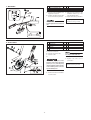
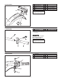
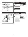
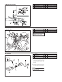
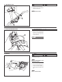
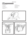
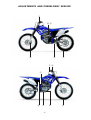
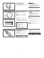
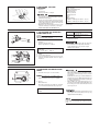
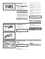
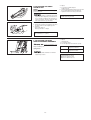
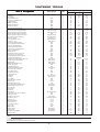
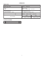
TT-R230T
TT-R230TC
ASSEMBLY MANUAL
LIT-11666-18-40
1C6-F8107-10
FOREWORD
This Assembly Manual contains the information required
for the correct assembly of this Yamaha motorcycle prior to
delivery to the customer. Since some external parts of the
motorcycle have been removed at the Yamaha factory for
the convenience of packing, assembly by the Yamaha dealer
is required. It should be noted that the assembled motorcycle
should be thoroughly cleaned, inspected, and adjusted prior to delivery to the customer.
SYMBOLS USED IN
THE ASSEMBLY MANUAL
In order to simplify descriptions in this assembly manual,
the following symbols are used:
Coat with lithium-soap-base grease.
Tighten to 10 Nm.
(10 Nm = 1.0 m • kg = 7.2 ft • lb)
NOTICE
The service specifications given in this assembly manual
are based on the model as manufactured. Yamaha Motor
Do Brasil Ltda is continually striving to improve all of its
models. Modifications and significant changes in
specifications or procedures will be forwarded to all
authorized Yamaha dealers and will appear in future editions
of this manual where applicable.
The procedures below are described in the order that the
procedures are carried out correctly and completely. Failure
to do so can result in poor performance and possible harm
to the motorcycle and/or rider.
Towards the front of the motorcycle.
Clearance required.
Install so that the arrow mark faces upward.
Apply motor oil.
Made of rubber or plastics
CONCERNING CRA
TE DAMAGE :
CRATE
Follow the instructions in the Dealer Warranty Handbook,
Procedure Section.
Particularly important information is distinguished in this
manual by the following notations.
The Safety Alert Symbol means ATTENTION! BECOME
ALERT! YOUR SAFETY IS INVOLVED!
Failure to follow WARNING instructions could result in
severe injury or death to the motorcycle operator, a
bystander, or a person checking or repairing the motorcycle.
A: Ref No. (indicating the order of operations.)
B: Part name
C: Quantity of parts per machine.
D: Place where parts are held.
V: Stored in plastic bag.
C: Stored in carton box.
S: Fixed inside the steel frame, and/or
contained in the Styrofoam tray (upper or
lower).
*: Temporarily installed or secured.
E: Size or material of parts.
d/D:Diameter of part.
l: Length of part.
A CAUTION indicates special precautions that must be taken
to avoid damage to the motorcycle.
e.g., 5= 5mm (0.2 in)
A NOTE provides key information to make procedures easier
or clearer.
TT-R230T / TT-R230TC
ASSEMBLY MANUAL
© 2004 by Yamaha Motor Do Brasil Ltda.
First Edition, December 2004
All rights reserved. Any reproduction or unauthorized
use without the written permission of
Yamaha Motor Do Brasil Ltda
is expressly prohibited.
Printed in U.S.A.
P/N LIT-11666-18-40
SETUP PROCEDURES
3 9
2
1 4 5 6 7 8 A B
0
C
1. Handlebar
D
A
1
2
Handlebar
Upper handlebar holder
1
2
C
V
3
Flange bolt
4
V
d=8 (0.32), L= 35 (1.38)
A: Clean the right handlebar end.
Apply light coat grease
C: Align the punch mark on the
handlebar with the top of the
B: Install the handlebar holders with
the arrow mark facing forward
lower handlebar holders.
D: Tighten the bolts to specification.
Tightening torque:
23 Nm (2.3 m.kg, 17 ft.lb)
First tighten the bolts on the front side,
and then tighten the bolts on the rear
side.
C
2. Front wheel
1
Front wheel
1
S
2
3
Wheel axle
Collar
1
2
*
V
4
5
Washer
Axle nut
2
1
*
*
A: Clean the brake disc.
B: Clean the front wheel axle.
C: Clean the collar.
D:
Do not depress the brake lever when
the caliper is off the brake disc.
F: Tighten
Take care not to get grease on the
brake disc or inner surface of the brake
pads. If you do so, clean using a rag
dampened with a solvent. Foreign material on braking surface can cause
impaired braking action
E: Lift the front wheel and install the
front wheel axle.
-4-
the
axle
nut
specification.
Tightening torque:
80 Nm (8.0 m.kg, 58 ft.lb)
to
3. Front fender
1
2
Front fender
Number plate holder
1
1
S
C
3
4
Collar
Collar
2
2
V
V
d=6
d=6 L=13,5(0,53)
5
6
Washer
Bolt
2
4
V
V
d=6 (0,24)
d=6 (0,24 L=30(1,2))
1
2
*
*
d=5 (0,20 L=16 (0.63))
d= 3 (0,12),L= 14 (0,55)
Tightening torque:
7 Nm (0.7 m.kg, 51 ft.lb)
4. Trottle grip
1
2
Trottle grip
Panhead screw
A: Check the throttle grip for
smooth action.
Proper cable routing is essential to
assure safe motorcycle operation.
Refer to “CABLE ROUTING”.
Tightening torque:
4 Nm (0.4 m.kg, 3,9 ft.lb)
5. Start switch
2
3
1
4
-5-
1
2
Start switch
Panhead screw
1
1
S
V
3
4
Start switch holder upper
Start switch holder lower
1
1
V
V
6. Master cylinder
1
2
Master cylinder
Master cylinder bracket
1
1
S
*
3
Bolt
2
*
d=6 (0,24) L=25 (0,98)
1
A: Lubricate the pivoting part of the
brake lever.
C
A
Proper hose routing is essential to
assure safe machine operation.
Refer to “CABLE ROUTING”.
Recommended lubricants:
Yamaha cable lube or motor oil
B: Make sure that the “UP” mark on
the bracket is pointed upward.
C: Check the brake lever for smooth
action.
2
UP
3
B
Tightening torque:
9 Nm (0,9 m.kg, 6.5 ft.lb)
9
7. Clutch cable
1
Clutch cable
1
*
2
Clutch switch lead
1
S
A: Lubricate the pivoting part of the
clutch lever.
Recommended lubricants:
Yamaha cable lube or motor oil
B: To install the clutch cable, be sure
to proceed as follows:
a.Turn in the adjuster on the lever
holder until tight. Next, align the
slit in the adjuster and cable socket
with the slit in the lever holder.
b.Insert the cable end into the lever
hole. Next, while pulling the outer
cable in the direction opposite to
the lever, seat the outer cable into
the cable socket.
-6-
Check the clutch lever for smooth
action.
Refer to “ADJUSTMENTS AND
PREDELIVERY SERVICE”.
Proper cable routing is essential to
assure safe motorcycle operation.
Refer to “CABLE ROUTING”.
8. Engine stop switch
9. Number plate
1
2
Engine stop switch
Panhead screw
1
1
S
V
3
4
Enginestopswitchholderupper
Enginestopswitchholderlower
1
1
V
V
1
Number plate
1
C
2
3
Collar
Bolt
1
1
V
V
Tightening torque:
7 Nm (0.7 m.kg, 5,1 ft.lb)
10. Footrest
1
2
Footrest
Clevis pin
2
2
C
V
3
4
Return spring
Cotter pin
2
2
V
V
A: Insert one end of the return spring
into the hole in the footrest and
hook the other end onto the
bracket.
B: Insert the cotter pin into the clevis
pin and bend the end of cotter pin.
After installing a footrest, check that
it operates smoothly.
-7-
d=3 (0,12), l= 14 (0,55)
d=6 (0,24 L=12 (0.47))
11. Handlebar band
1
Band
4
V
1
C
A: Clamp the start switch lead
B: Clamp the engine stop switch lead
and clutch switch lead.
Refer to “CABLE ROUTING”.
12. Fuel tank breather hose
1
Fuel tank breather hose
A: Connect one side of the fuel tank
breather hose to the tank cap pipe
and insert the other side to the
stearing shaft cap.
Refer to “CABLE ROUTING”.
13. Battery
1
Battery
1
C
2
Band
1
C
A: Installing the battery.
Refer to “ADJUSTMENTS AND
PREDELIVERY SERVICE”.
B: First, connect the positive lead (red
lead) to the positive terminal.
C: Second, connect the negative lead
(black lead) to the negative terminal.
Refer to “CABLE ROUTING”.
-8-
CABLE ROUTING
Proper cable and lead routing is essential to ensure safe motorcycle operation.
1 Fuel tank breather hose
8 Brake hose
2 Throttle cable
9 Starter relay lead wire
3 Start switch lead
0 Starter motor lead wire
4 Clutch cable
A Wire plus lead
5 Clutch switch lead
B CDI unit lead
6 Engine stop switch lead
C Wire minus lead
7 Main harness
-9-
ADJUSTMENTS AND PREDELIVERY SERVICE
I
B D
H
K
E
F G
L
A
J
-10-
C
E
A. CHECKING AND CHARGING
THE BATTERY
•
1 . Fill:
•
•
•
•
•
•
•
Never remove the sealing sheet (aluminum seal)
from the battery until the battery is filled with
electrolyte.
If battery plates are exposed to air, they will
oxidize. As a result, power will not be generated
as specified.
Use only the amount of electrolyte in the container
which comes with the battery.
An incorrect electrolyte level has an adverse
effect on battery performance.
The quantity of electrolyte varies with the type
of the electrolyte container.
Avoid using any electrolyte other than specified.
The specific gravity of the MF battery electrolyte
is 1.320 (20ºC). (the specific gravity of the
general type battery electrolyte is 1.280.) If the
electrolyte whose specific gravity is less than
1.320, the sulfuric acid will decrease and thus
low battery performance will result.
Should any electrolyte, whose specific gravity is
1.320 or more, be used, the battery plates will
corrode and battery life will shorten.
a. Place the battery on a level surface.
b. Remove the sealing shee
Filler port
c. Take the electrolyte container out of the vinyl
bag.
d. Detach the strip of caps (used as battery plugs).
Six sealed areas of container
Do not lose the strip of caps because it will be used
as battery plugs.
Do not peel or pierce the sealed areas.
e. Turn the electrolyte container upside-down with
the six sealed areas in line with the six filler ports
of the battery.
f. Push the container down with enough force to
break the seals. The electrolyte will start to flow
into the battery.
•
•
Do not tilt the container as the electrolyte may
stop flowing.
Never remove the container from the battery
until all electrolyte has drained from the container.
g. Leave the container in this position for 20 minutes
or longer to allow proper chemical reaction.
•
•
Make sure air bubbles are rising from all six filler
ports.
If air bubbles are not rising from a filler port, tap
the top of the container a few times.
h. Make sure that all the electrolyte has been drained
from the container.
i. Fit the strip of caps (battery plugs) securely into
the filler ports. Make sure the top of the strip is
flush with the top of the battery.
Press down with equal force with both hands.
•
Never remove the strip of caps, nor add any
water or electrolyte.
-11-
Do not attempt boost charging under any
circumstances.
Battery electrolyte is poisonous and dangerous,
causing severe burns, etc. It contains sulfuric
acid. Avoid contact with skin, eyes or clothing.
Antidote: External -Flush with water. InternalDrink large quantities of water or milk. Follow
with milk of magnesia, beaten egg, or vegetable
oil. Call physician immediately.
Eyes: Flush with water for 15 minutes and get
prompt medical attention. Batteries produce
explosive gases. Keep sparks, flames, cigarettes,
etc., away. Ventilate when charging or using in
enclosed space. Always shield eyes when
working near batteries.
KEEP OUT OF THE REACH OF CHILDREN.
2 . Check:
Using a digital volt meter, the state of a discharged
MF battery can be checked by measuring opencircuit voltage (the voltage measured with the
positive and negative terminals being
disconnected).
The battery must charged after it is filled with
electrolyte. If this is not done, the life of the
battery will be shortened drastically. Since the
procedure for charging the battery is not
explained in the assembly manual, refer to the
service manual for more details.
B. DRAINING THE FUEL
1. Turn the fuel cock to “OFF”
2 . Put a rag under the carburetor drain hose so fuel
does not contact the crankcase.
3 . Loosen the drain screw (1) and drain the standing
fuel.
FUEL IS HIGHLY FLAMMABLE:
• Always turn off the engine when draining fuel.
Take care not to spill any fuel on the engine or
exhaust pipe(s)/muffler(s) when draining fuel.
• Never drain fuel while smoking or in the
vicinity of an open flame.
4 . Tighten the drain screw securely.
C. CHECKING THE ENGINE OIL
LEVEL
1 . Stand the motorcycle on a level surface.
•
•
Place the motorcycle on a suitable stand.
Make sure that the motorcycle is upright.
2 . Check:
• engine oil level
The engine oil level should be between the
minimum level marks (a) and maximum level
marks (b).
Below the minimum level mark → Add the
recommended engine oil to the proper level.
Recommended engine oil
YAMLUBE 4
At -10ºC (10ºF ) or higher (A)
SAE 10W30 engine oil
At 5ºC (40ºF ) or lower (B)
SAE 20W40 engine oil
Quantity
Without oil filter element replacement
1.0 L (1.1 Imp qt, 0,90 US qt)
D.ADJUSTING THE ENGINE
IDLING SPEED
1 . Start the engine and let it warm up for several
minutes.
2 . Check:
Engine idling speed by using a tachometer
Out of specification → Adjust.
Engine idling speed
1.400 ~ 1.600 r/min
-12-
• Engine oil also lubricates the clutch and the
wrong oil types or additives could cause
clutch slippage. Therefore, do not add any
chemical additives.
• Do not allow foreign materials to enter the
crankcase.
API Service “SE”, “SF” and “SG” type or equivalent
(e.g., “SF-SE”, “SF-SE-CC”, “SF-SE-SD”)
3 . Start the engine, warm it up for several minutes,
and then turn it off.
4 . Check the engine oil level again.
Before checking the engine oil level, wait a few
minutes until the oil has settled.
3. Adjust:
• Turn the throttle stop screw in direction (a) or
(b) until the specified engine idling speed is
obtained.
Direction (a)
Direction (b)
Engine idling speed is increased.
Engine idling speed is decreased.
E. MESURING THE TIRE
PRESSURE
Basic weight:
With oil and full fuel tank
116.0 kg (256 lb)
Maximum load*
90.0 kg (198 lb)
Cold tire pressure
Front
Rear
Off road riding
100 kPa (1.00 kgf/cm<SUP2>, 15 psi)
100 kPa (1.00 kgf/cm<SUP2>, 15 psi)
1. Measure:
• Tire pressure
Out of specification → Adjust.
• The tire pressure should only be checked and
regulated when the tire temperature equals the
ambient air temperature.
• The tire pressure and the suspension must be
adjusted according to the total weight (including
cargo, rider, passenger, and accessories) and
the anticipated riding speed.
• Operation of an overloaded motorcycle could
cause tire damage, an accident, or an injury.
NEVER OVERLOAD THE MOTORCYCLE.
*Load is the total weight of cargo, rider, and
accessories.
F. ADJUSTING THE THROTTLE
CABLE FREE PLAY
Direction (a)
Direction (b)
Prior to adjusting throttle cable free play, the engine
idling speed should be adjusted.
Throttle cable free play
is increased.
Throttle cable free play is
decreased.
c. Tighten the locknut.
1 . Measure:
• Throttle cable free play (a)
Out of specification → Adjust.
After adjusting the throttle cable free play, turn
the handlebar to the right and to the left to
ensure that this does not cause the engine
idling speed to change.
Throttle cable free play (at the flange of the
throttle grip)
3 ~ 5 mm (0,12 ~ 0,20 in)
2 . Adjust:
a. Loosen the locknut (1).
b. Turn the adjusting nut (2) in direction (a) or (b)
until the specified throttle cable free play is
obtained.
G. CHECKING THE BRAKE FLUID
LEVEL
•
1 . Stand the motorcycle on a level surface.
•
•
Place the motorcycle on a suitable stand.
Make sure that the motorcycle is upright.
2 . Check:
• Brake fluid level
Below the minimum level mark (a) → Add the
recommended brake fluid to the proper level.
Recommended brake fluid
DOT 4
•
•
Use only designated brake fluid.
Other brake fluids may cause the rubber seals to
deteriorate, causing leakage and poor brake
performance.
Refill with the same type of brake fluid that is
already in the system. Mixing brake fluids may
result in a harmful chemical reaction, leading to
poor brake performance.
When refilling, be careful that water does not
enter the reservoir. Water will significantly lower
the boiling point of the brake fluid and could
cause vapor lock.
Brake fluid may damage painted surfaces and
plastic parts. Therefore, always clean up any
split brake fluid immediately.
In order to ensure a correct reading of the brake fluid
level, make sure that the top of the reservoir is
level.
-13-
H. BLEEDING THE HYDRAULIC
BRAKE SYSTEM
Bleed the hydraulic brake system whenever:
• the system was disassembled,
• a brake hose was loosened or removed,
• the brake fluid level is very low,
• brake operation is faulty.
A dangerous loss of braking performance may occur
if the brake system is not properly bled.
•
Be careful not to spill any brake fluid or allow the
brake master cylinder reservoir to overflow.
When bleeding the hydraulic brake system, make
sure that there is always enough brake fluid before
applying the brake. Ignoring this precaution could
allow air to enter the hydraulic brake system,
considerably lengthening the bleeding procedure.
If bleeding is difficult, it may be necessary to let
the brake fluid settle for a few hours. Repeat the
bleeding procedure when the tiny bubbles in the
hose have disappeared.
•
•
a. Add the recommended brake fluid to the proper
level.
b. Install the brake master cylinder reservoir
diaphragm.
c. Connect a clear plastic hose (1) tightly to the
bleed screw (2).
d. Place the other end of the hose into a container.
e. Slowly squeeze the brake lever several times
and release it.
f. Fully squeeze the brake lever and do not release
it.
g. Loosen the bleed screw. This will release the
tension and cause the brake lever to contact the
throttle grip.
h. Tighten the bleed screw and then release the
brake lever.
i. Repeat steps (e) to (h) until all of the air bubbles
have disappeared from the brake fluid in the
plastic hose.
j. Tighten the bleed screw to specification.
Bleed screw
6 Nm (0,6 m.kg, 4,3 ft.lb)
k. Fill the reservoir to the proper level.
Refer to “CHECKING THE BRAKE FLUID LEVEL”.
Air bleeding steps:
After bleeding the hydraulic brake system, check
the brake operation.
I. ADJUSTING THE CLUTCH
CABLE FREE PLAY
1 . Measure:
• Clutch cable free play (a)
Out of specification → Adjust.
Clutch cable free play (at the pivot point of the
clutch lever)
10 ~ 15 mm (0,39 ~ 0,59 in)
Handlebar side
a. Loosen the locknut (1).
b. Turn the adjusting bolt (2) in direction (a) or (b)
until the specified clutch cable free play is
obtained.
Direction (a)
Direction (b)
Clutch cable free play is increased.
Clutch cable free play
is decreased.
c. Tighten the locknut.
2 . Adjust:
• Clutch cable free play
J. ADJUSTING THE REAR
BRAKE
1. Measure:
• Brake pedal free play a
Out of specification → Adjust.
Free play
20 ~ 30 mm (0,8 ~1,2 in)
2.
•
a.
b.
Adjust:
Brake pedal free play
Loosen the locknuts 1.
Turn the locknuts until free play is within the
-14-
specifiead limits by changing their tightenirig
position.
Make sure that there is no Brake drag after
adjusting the brake pedal free play.
K. ADJUSTING THE DRIVE
CHAIN SLACK
The drive chain slack must be checked at the tightest
point on the chain.
1
A drive chain that is too tight will overload the
engine and other vital parts, and one that is too
loose can skip and damage the swingarm or
cause an accident. Therefore, keep the drive
chain slack within the specified limits.
4. Adjust
a. Loosen the rear brake adjuster
and the axle nut
b. Turn the adjusting plate in direction a or b until
the specified drive chain slack is obtained
c. Tighten the wheel axle nut to specification
Tighteniny torque:
80 Nm (8.0 m.kg, 58 ft.lb)
8
1 . Stand the motorcycle on a level surface.
2 . Rotate the rear wheel several times and check
the drive chain to locate its tightest point.
3 . Measure:
• drive chain slack (a)
Out of specification → Adjust.
Drive chain slack
45 ~ 60 mm (1,77 ~ 2,36 in)
L. ADJUSTING THE REAR
SHOCK ABSORBER ASSEMBLY
Securely support the motorcycle so that there is no
danger of it falling over.
1.
•
a.
b.
Adjust:
Spring preload
Loosen the locknut
Turn the adjusting nut in direction a or b.
Direction (a)
Spring preload is increased
(suspension is harder).
Direction (b)
Spring preload is decreased
(suspension is softer).
Spring preload
Never go beyond the maximum or minimum
adjustment positions.
-15-
Adjusting positions
Standard: 204 mm (8.0 in)
Minimum: 194 mm (7.6 in)
Maximum: 206 mm (8.1 in)
TIGHTENING TORQUE
Tightening torque
Part to be tightened
Description
Qty
Bolts
Bolts
Bolt
Bolt
Bolt
Bolt
Bolt
Nut self-locking
Nut self-locking
Bolt
Nut self-locking
Nut self-locking
Bolt flange
Bolt with washer
Bolt, Flange
Nut
Nut
Bolt
Bolt
Bolt
Nut
Nipple
Nut
Nut
Nut
Nut
Bolt, Flange
Bolt, Flange
Bolt, Flange
Bolt, Flange
Bolt
Bolt
Bolt, Flange
Bolt
Nut
Axle
Bolt
Nut, self locker
Bolt, Flange
Bolt
Bolt
Screw
Pin
Bolt, flange
Bolt, flange
Bolt
Bolt
Bolt
NUT self locking
Bolt
Bolt
Screw, bind
Bolt, with washer
Screw
Screw
Screw
Bolt
Screw
Bolt
Bolt, flange
Bolt, flange
Bolt, flange
-
Nm
m.kg
ft.lb
1
1
2
1
3
2
1
3
2
17.5
43
10
10
10
40
16
7
10
1.75
4.3
1
1
1
4
1.6
0.7
1
12.9
31.7
7.2
7.2
7.2
29.5
11.8
5.1
7.2
2
2
2
1
1
3
1
1
1
1
1
2
2
1
2
1
1
1
1
2
2
1
2
2
2
2
1
1
1
1
1
2
1
2
1
2
6
2
4
4
2
1
6
2
4
3
1
1
2
2
2
2
2
2
1
1
46
46
37.5
32.5
46
54.5
7
23
52.5
52.5
52
7
7
80
4
34.5
34.5
110
4.6
4.6
3.75
3.25
4.6
5.45
0.7
2,3
5.25
5.25
5.2
0.7
0.7
8
0.4
3.45
3.45
11
SEE NOTE
2.3
2
0.7
0.7
0.7
2
2
2
8
3
0.7
4.35
4.75
3
0.7
0.4
1.8
1.3
4
0.7
0.7
0.3
8
3.45
1
2.5
0.7
0.7
0.7
0.7
9.75
0.7
0.7
0.7
9.75
0.7
2
33.9
33.9
27.7
24
33.9
40.2
5.1
16.9
38.7
38.7
38.3
5.1
5.1
59
2.9
25.5
25.5
81.1
Engine
Spark Plug
Plug, drain
Cover, Oil Element
Drain Screw, Oil Element
Spark Arrester
Muffler and Frame
Muffler and Exhaust
Exhaust Protector
Exhaust and Cylinder Head
Frame
Engine stay (front under) and frame
Engine stay (front under) and engine
Engine stay (font upper) and frame
Engine stay (front upper) and engine
Engine (rear under) and frame
Protector, Engine
Tensioner Chain - under
Tensioner - rear
Connecting Rod and Frame
Connecting Rod and Arm Relay
Rear arm and Arm Relay
Chain guide and Rear Arm
Chain Protector and Rear Arm
Engine and Rear Arm
Nipple, grease
Arm Relay and rear suspension
Rear Suspension and Frame
Under bracket and Handle Crown
Hand Crown and Ring nut
Handle under holder and handle crown
Handle Crown and Inner tube
Number plate
Bracket and Handle Crown
Hose brake clamp
Cable Guide (Upper)
Under bracket and Inner tube
Base Valve and outer tube
Front Wheel axle
Pedal, brake (shaft)
Shift pedal level
Sidestand
Footrest
Hose brake
Bracket master cylinder
Bleed screw
PIN PAD, Caliper Assy
Front brake disc and Wheel hub
Brake Caliper and front Fork
Front Fender
Rear fender
Flap Guar
Rear Wheel
Sprocket Driven and Rear Wheel
Carburetor Joint
Air Cleaner Case Cap
Air Cleaner Case
Bracket seat
Band, tank fitting
Fuel cock assy
Fuel tank and frame
Scoop, air
Battery Box
Starter Relay
Ignition Coil
Rectifier and regulator
Neutral switch
23
20
7
7
7
20
20
20
80
30
7
43.5
47.5
30
7
6
18
13
40
7
7
3
80
34.5
10
25
7
7
7
7
97.5
7
7
7
97.5
7
20
16.9
14.7
5.1
5.1
5.1
14.7
14.7
14.7
59
22.1
5.1
32
35
22.1
5.1
4.4
13.2
9.5
29.5
5.1
5.1
2.2
59
25.5
7.2
18.4
5.1
5.1
5.1
5.1
71.9
5.1
5.1
5.1
71.9
5.1
14
NOTE:
1. First tighten the ring nut approximately 43 Nm (4.3 m.kg, 31.7 ft.lb) by using the ring nut wrench and turn the steering right and left a few times; then
loosen the ring nut 1/4 turn.
2. Retighten the ring nut 6.5 Nm (0.65 m.kg, 4.8 ft.lb)
-16-
APPENDICES
SERVICE DATA
TTR230T
Engine idling speed:
1,400 ~ 1,600 r/min
Spark plug:
Type
Gap
DR8EA (NGK)
0.024 ~ 0.028 in (0,6 ~ 0,7 mm )
Fuel:
Recommended fuel
Fuel tank capacity
Unleaded gasoline only
2,11 US gal (1,76 Imp gal, 8.0 L)
Total:
Valve clearance (cold):
IN
EX
0.0020 ~ 0.0035 in (0,05 ~ 0,09 mm)
0.0060 ~ 0.0075 in (0,15 ~ 0,19 mm)
Tire pressure
Off-road riding
STANDARD EQUIPMENT
No.
1
Part name
Owner’s manual
Q’ty
1
-17-
Front
Rear
14.5 psi
(1 kgf/cm2, 100 kPa)
14.5 psi
(1 kgf/cm2, 100 kPa)
YAMAHA MOTOR DO BRASIL LTDA
PRINTED IN U.S.A.