1
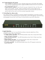
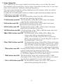
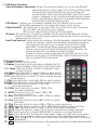
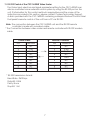
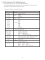
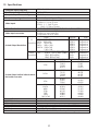
Video Scaler Operation Manual 1. Introduction Congratulations on your purchase of the Cypress Video Scaler CSC-1600HD.Our professional video Scaler products have been serving the industry for many years. In addition to VideoScalers, Cypress offers a full line of high quality PC multimedia , Standards Converters, DV-to-Analog Converters,Vieo Mixer, Time Base Correctors, and video processors, Please visit www.cypress.com.tw to learn more details about these products. This manual includes operation information on the CSC-1600HD model. Please read this to become familiar with the CSC-1600HD. and keep the manual for possible reference in the future. Cypress's CSC-1600HD is designed to convert Composite S-Video and YCbCr signals to a variety of computer and HDTV resolutions. It handles video input from all TV systems NTSC, PAL and SECAM TV standards. Cypress CSC-1600HD has many great features to enhance performance and is ideal for use in professional large screen presentation studio. 2. Features 1. Video inputs are de-interlaced and scaled up to output resolution as below * PC output : 640x 480, 800x 600 (SVGA), 1024 x768 (XGA), 1280 x 1024(SXGA), 1280 x 768(WXGA), 1365 x 768 * HDTV output: 852 x 480 P, 852 x 576P 1280 x 720 P 16:9 1920 x 1080i 16:9 2. Automatically accommodates worldwide input video systems of NTSC 3.58, NTSC 4.43, PAL, PAL M, PAL N, and SECAM. 3. High performance adaptive 4H Comb filter Y/C separator with adjustable vertical peaking. 4. Per-pixel motion compensated deinterlacing algorithms to produce artifact-free progressive scan video signal. 5. Built in Adaptive film mode 3:2 pull-down provides clear and crisp de-interlacing of video originating from 24 fps film,such as DVD movies. 6. Frame rate up conversion from 50 up to 75Hz (PAL), or 60 up to 85Hz(NTSC) 7. Vertical temporal filter(VT) removes jaggy and other de-interlacing artifacts from normal video. 8. OSD menu with adjustable control on Color,Sharpness,Brightness,Contrast and Tint(NTSC). 9. Built-in DCTI/DLTI circuit for color/luminance transient improvement. 10. The PC loop-through allows for easy change between video and PC source. 11. Last memory for all adjustments. 12. RS-232 interface allows remote control from PC. 3. Checking the Package Contents The following items are contained in shipping carton: 1. Video Scaler Unit 2. AC Power Cord x 1 3. VGA Cable-HD 15 to HD 15 x 1 4. 1BNC-1BNC video cable x 1 5. S-Video Input Cable 6. BNC 5 to 5 BNC Cables 7. YCbCr 3 RCA- to 3 RCA cable x 1 8. User Manual 9. Remote Control 10.4 x Rackmount Screws (Rackmount Vertions only) 11. Sample Windows Control Panel Software 12. 2 x 4A battery 13. 3 x RCA-M to BNE-F Adaptor 1 4. Connecting the hardware The first step is to connect a video source to the input of the Video Scaler and to connect its output to a display device. Below is a photo of the CSC-1600HD rear panel. INPUT SELECT YCbCr C-VIDEO POWER S-VIDEO PC OUTPUT SELECT XGA VGA SVGA 480p/YPbPr 576p/YPbPr 720p SXGA WXGA 1080i 1365X768 ADJUSTMENT ENTER MENU CSC-1600HD VIDEO SCALER R/Pr YPbPr G/Y RGBHV B/Pb OUTPUT H INPUT V HD-15 PC S-VIDEO C-VIDEO Y YCbCr Cb AC 100~240V 50~60Hz Cr RS232 4.1 Rack Mounting The CSC-1600HD unit can be mountable in a standard 19" (1 RU) EIA rack assembly. Desktop versions can be converted to rackmount versions by changing the unit's front panel. Plaese contact our Service Department should assistance be required with this conversion. 4.2 Connecting the Vieo Inputs The Video Scaler can accept a Composite Video, an S-Video or an YCbCr input signal for scaling, as well as a computer signal input that is passed through the unit when the PC In (Bypass) is selected. * Composite Video- use a Composite Video cable to connect the composite Video output of the source equipment to the connector labeled " C-Video" on the back of the Video Scaler. * S-Video - use a S-Video cable to connect the S-Video output of the source video equipment to the connector labled " S-Video" on the back of the Video Scaler. S-Video provides improved performance over Composite Video and is recommended over composite. * YCbCr Input - use a 3 rca-to- 3 rca YCbCr cable to connect the YCbCr output of the source video equipment to the connectors labled YCbCr on the back of the video scaler. Please note the plugs' color haue to match with the color of the RCA Jacks. YCbCr composite provides the best picture quality among all three inputs, and should be used whenever possible. * Computer RGB with H&V Sync- Connect the source computer's VGA output signal to the HD 15 connector labled " PC In" on the back of the Video Scaler. Note - This Computer input Signal is not scaled, but is available for pass-through when the Video Scaler is in the PC In (Bypass) Mode. 4.3 Connecting the scaled output to your projector, HDTV, PC monitor or LCD DisplayCSC-1600HD has two sets of output connectors for you to choose from the HD-15 D-sub and the RGBHV BNC jacks. Only one of the two output terminals has signal running on it at one time. When one output terminal is selected the other terminal will have no output signal. You can use the two buttons (HD-15 and BNC) on the remote control to choose your desired output or you could go to the "Output terminal" tool bar under the ON Screen Menu to choose the terminal you want. The 5 BNC jacks are shared by RGBHV output and YPbPr output. When 480P or 576P output resolution is selected the three BNC jacks from the most left to the center will carry Pr,Y and Pb correspondingly. In this case only three plugs are needed to connect the YPrPb output to the destination TV/Monitor. For output mode other then 480P or 576P the BNC jacks from left to right,will carry RGBHV signal respectively. In such a care, all BNC plugs of the 5 BNCs cable are needed to connect RGBHV output to the destination TV/Monitor. 2 4.4 Connecting the AC power CSC-1600HD accepts AC input voltage range from 100~240V (50~60HZ). The unit has a switching power supply installed inside that will convert the AC input to 12V DC 1A. * Power ON/OFF switch-Once the AC power is feed into the unit, the unit enter into standby mode, where a limited current is provided to the micro processor to allow the remote control to work. Press the power on switch will turn the unit on to the normal operation status. 5. Controlling the video scaler The video Scaler is controlled via Front Panel Push Buttons or remote control and its status is indicated by Front Panel LED's, and OSD Display. The following photograph shows the Front Panel Control Buttons and LED Indicators. 6. Input Selection Pressing one of the four input Buttons allows manual selection of the corresponding Video Input signal. * C-Video button and LED - The LED illuminates when the composite Video input has been selected. * S-Video button and LED - The LED illuminates when the S-Video input has been selected. * YCbCr button and LED - The LED illuminates when the component. YCbCr (or YUV) input has been selected. * PC button and LED - The LED illuminates when the PC bypass mode has been selected. 3 7. Output Selection CSC-1600HD has ten output selection buttons allow you to directly select the desired output resolution. Some output resolution mode may cover more than one horizontal /vertical scanning frequency. This scan rate information will be displayed on the screen when an output selection button is pressed. To alter the scanning rate under a certain output resolution please refer to "ODS menu operation" selection. * VGA button and LED -This LED illuminates when the 640 x 480 has been selected by pressing the button. * SVGA button and LED - This illuminates when 800 x 600 output has been selected by presing the button. * XGA button and LED - This illuminates when 1024 x 768 output has been selected by pressing the button. * SXGA button and LED - This illuminates when 1280 x 1024 output has been selected by pressing the button. * WXGA button and LED - This illuminates when 1280 x 768 has been selected by pressing the button. * 480p/YPbPr button and LED - This illuminates when 480p (852 x 480p) has been selected by pressing the button. while in this mode, only Pr/Y/Pb Connectors (BNC) are required for connecting the output to the displaying TV/Monitor. * 576p/YPbPr button and LED - This illuminates when 576p (852 x 576p) has been selected by pressing the button. While in this mode, only Pr/Y/Pb connectors (BNC) are required for connecting the output to the displaying TV/Monitor. * 720p button and LED - This illuminates when the HDTV quality 720P (1280 x 720) output is selected by pressing the button. The aspect ratio of the output picture will be converted to 16:9 from original 4:3 on the video input. * 1080i button and LED - This illuminates when the interlacted HDTV 1080i The aspect ratio of the output picture will be converted to 16:9 from original 4:3 on the video input. * 1365 x 768 button and LED - This illuminates when the 1365 x 768 output is selected by pressing the button. 4 8. Picture Adjustment The picture adjustments along with other controls of the scaler can be achieved by using OSD menu control. 9. OSD Menu Operation The MENU, + , - and enter buttons are used in the on screen menu control operation. MENU - This button serves two purposes to show drop-down menu of main menu page and to act as " exit " when an adjustment is complete. Press this button while on main menu page will exit the menu operation. ENTER - Press the button to confirm your selection of the paramenter you want to adjust. + - Press the button to move the highlight bar upwardly from one paramerter to another. Or when an adjustment paramerter is selected press the button to increase the setting value. - Press the button to move the highlight bar downwardly from one parameter to another. When an adjustment parameter is selected press the button to decrease the setting value. Note: When a menu or sub-menu pape is selected, but if there is no activity for about seven seconds, the unit automatically revert to normal mode and the OSD disappear. Main Menu- Press the menu button will enter into main menu page shown as follows Video Adjust Vertical Freq Adjust OSD display Output Terminal IR sensor Front Panel Lockout Use + , - button to choose the parameter you want to adjust. When a parameter is selected it is hightlighed in red color. Press ENTER button to enter into the selected adjustment page. Video Adjust- When video adjust page is selected, it will show picture paramenters as below: Brightness Contrast Color Sharpness Tint Reset Use + , - button to choose the paramenter you wish to adjust and then press enter to get down to value adjust sub-menu. Use +/- to increase/ decrease the value. use menu to exit afterward. The adjustment range for each paramenter are as follows : Brightness 0~255 Contrast 0~63 Color 0~127 Tint -30~+30 Press reset to return all value back to factory preset position which is the middle value of each adjust range. 5 9. OSD Menu Operation Vertical frequency rate adjust- When it is selected it allows you to choose different vertical frequency while under VGA, SVGA or XGA modes. The higher the vertical refresh rate the less flicker the picture will be. When the vertical refresh rate of an output mode is changed, so will its horizontal scanning rate. please refer to specification page-for cross relationship between vertical and horizontal scanning rate. OSD display- It allows you to enable or disable the OSD display of the output information appeared on the upper left corner of the screen. Output Terminal - This allows you to choose which one of the two output terminals, HD-15 or BNC, will have the output signal. When one is selected the other won't have signal. IR Sensor- This allows you to enable or disable the IR sensor for the Remote control. When it is disabled the command issued from the remote control can not be received by the main unit. Front Panel Lockout- Under certain circumstances it may be desirable to disable the Front Panel Conrols. For example, to prevent unauthorized or accidental changes to the setting while the unit is in use. To disable the Front Panel Controls. press MENU, choose the Front Panel Lockout section and press ENTER. Then you may choose Front Panel Controls OFF. In the OFF position, the unit will not respond to commands from the Front Panel. To return to normal operation, press and hold simultaneously the + and buttons for 3 seconds or use the IR Remote Control to gain access to the Menu or use the RS-232 commaands. 10. Remote Control POWER DISPLAY 1. Power: Power ON/OFF button. 2. Display: Press the button to enable or disable the ON XGA VGA SVGA C-VIDEO Screen Display of the input/output information. 3. C-Video: Press the button to select composite video SXGA WXGA 480p S-VIDEO as input source. 4. S-Video: Press the button to select S-Video as input source. 576p 1080i 720p YCbCr 5. YCbCr: Press the button to select YCbCr as input source. 6. PC: Press the button to select PC input looping through 1365X768 PC to the output. 7. VGA: Press the button to slect 640 x 480 as output resolution. 8. SVGA: Press the button to select 800 x 600 as output resolution. BNC HD-15 9. XGA: Press the button to select 1024 x 768 as output resolution. CR-16 10. SXGA: Press the button to select 1280 x 1024 as output resolution. ENTER MENU 11. WXGA: Press the button to select 1280 x 768 as output resolution. 12. 480p: Press the button to select 852 x 480p as output resolution. 13. 576p: Press the button to select 852 x 576p as output resolution. 14. 720p: Press the button to select 1280 x 702p as output resolution. 15. 1080i: Press the button to select 1920 x 1080i (interlaced) as output resolution. 16. 1365 x 768: Press the button to select 1365 x 768 as output resolution. 17. HD-15: Press the button to select 15 pin D-sub connector as output terminal. 18. BNC: Press the button to select RGBHV BNC connector as output terminal. 19. Menu: Press the button to enter into main menu page or to exit from a sub-menu. 20. Enter : Press the button to confirm your selection of an adjustment parameter. 21. : Press the or to move up or move down the hight-light bar to a desired parameter. 22. : Press the button to increase or decrease the value of the selected parameter. 6 11. RS-232 Control of the CSC-1600HD Video Scaler The Video Input selection and signal parameter setting for the CSC-1600HD can also be controlled via an external control system by using the RS-232 port on the unit. If information for this control method is required,beyond the scope of the instructions provided in this section, please contact Cypress Technology Support, A disk is provided with the CSC-1600HD containing a sample Windows Control Panel that permits remote control of the unit from a PC via RS-232. Note- The connection between the CSC-1600HD unit and the RS-232 remote controller is made with a modem cable. * The Connection between video scaler and remote controller with RS-232 modem cable. Video Scaler Definition PIN NC 1 T xD 2 RxD 3 NC 4 GND 5 NC 6 NC 7 NC 8 NC 9 * RS-232 transmission format: Baud Rate : 9600 bps Data Bit : 8 Bits Parity: None Stop Bit: 1 bit 7 Remote Controller Definition PIN NC 1 R xD 2 TxD 3 NC 4 GND 5 NC 6 NC 7 NC 8 NC 9 11. RS-232 Control of the CSC-1600HD Video Scaler * Command / Response codes of RS-232 transmission: the Command/ response codes are the combination of 3 bytes. the 1st, 2nd byte are text and the 3rd byte is value. Remote Controller Command Codes: Code 'PW' + 0 'PW' + 1 'IN' + 0 'IN' + 1 'IN' + 2 'IN' + 3 'JA' + 0 'JA' + 1 'OU' + 0 'OU' + 1 'OU' + 2 'OU' + 3 'OU' + 4 'OU' + 5 'OU' + 6 'OU' + 7 'OU' + 8 'OU' + 9 'DI' + 0 'DI' +1 'BR'+ value 'CO' + value 'SA' + value 'SH' + value 'TI' + value 'RE' + 0 'ZV' + value 'ZS' + value 'ZX' + value 'IR' + 0 'IR' + 1 'FP' + 0 'FP' + 1 'AL' + 0 Comment power off (standby) power on (normal) Composite video S-Video INPUT YCbCr PC Bypass HD-15 (D-Sub) JACK BNC VGA 480p SVGA XGA OUTPUT SXGA 576p 720p 1080i WXGA 1365 X 768 OSD display OFF DISPLAY OSD display ON Brightness value= 0~255 Contrast value= 0~63 Saturation value= 0~127 Sharpness value= 0~14 Tint value= -30~+30 reset video adjustment reset VGA vert freq value = 0:60hz 1:72hz 2:75:hz 3:85hz SVGA vert freq value = 0:60hz 1:72hz 2:75hz 3:85hz XGA vert freq value = 0:60hz 1:70hz 2:75hz IR sensor OFF IR IR sensor ON PANEL front panel lockout ON front panel lockout OFF retrive video scaler all status 'PW'+? 'IN' +? 'JA'+? 'OU'+? 'DI' +? 'IR'+? 'FP' +? 'BR'+? 'CO' +? 'SA'+? 'SH'+? 'TI' +? 'ZV'+? 'ZS' +? 'ZX'+? POWER 8 11. RS-232 Control of the CSC-1600HD Video Scaler * Command / Response codes of RS-232 transmission: the Command/ response codes are the combination of 3 bytes. the 1st, 2nd byte are text and the 3rd byte is value. Video Scaler transimits codes to Remote Controller when scaler operating. Code 'PW' + 0 'PW' + 1 'IN' + 0 'IN' + 1 'IN' + 2 'IN' + 3 'A' + 0 'JA' + 1 'OU' + 0 'OU' + 1 'OU' + 2 'OU' + 3 'OU' + 4 'OU' + 5 'OU' + 6 'OU' + 7 'OU' + 8 'OU' + 9 'DI' + 0 'DI' +1 'BR' + value 'CO' + value 'SA' + value 'SH' + value 'TI' + value 'RE' + 0 'ZV' + value 'ZS' + value 'ZX' + value 'IR' + 0 'IR' + 1 FP' + 0 'FP' + 1 'OK' + 0 POWER INPUT JACK OUTPUT DISPLAY IR PANEL Comment power off (standbt) power on (normal) Composite video S-Video YCbCr PC Bypass HD-15 (D-Sub) BNC VGA 480p SVGA XGA SXGA 576p 720p 1080i WXGA 1365 X 768 OSD display OFF OSD display ON Brightness value= 0~255 Contrast value= 0~63 Saturation value= 0~127 Sharpness value= 0~14 Tint value= -30~+30 reset video adjustment reset VGA vert fre value = 0:60hz 1:72hz 2:75:hz 3:85hz SVGA vert fre value = 0:60hz 1:72hz 2:75hz 3:85hz XGA vert fre value = 0:60hz 1:70hz 2:75hz IR sensor OFF IR sensor ON front panel lockout ON front panel lockout OFF Video scaler power plugs in ready 9 12. Specifications Computer input (Loop thru) Max Computer Input Resolution Computer Input Connector Type Computer Input signal Level RGB with HV Sync 1600 x 1200 HD 15 Female RGB @ 0.7V, H&V Sync @ TTL Composite Video @ 1 Vp-p 75 ohm S-Video @ 1 Vp-p 75 ohm Video Inputs YCbCr Y : 1 Vpp 75 ohm CbCr : 0.7 Vp-p 75 ohm NTSC 3.58, NTSC 4.43, PAL B/D/G/I PAL-N, PAL-M, SECAM Video Standard Composite Video on BNC S-Video on 4-pin Mini-DIN Video Input connectors Component or RCA Jacks Pixels Format Scan VGA 640 x 480 RGBHV Progressive PC SVGA 800 x 600 RGBHV Progressive Resolution XGA 1024 x 768 RGBHV Progressive Scaled Output Resolutions SXGA 1280 x 1024 RGBHV Progressive WXGA 1280 x 768 RGBHV Progressive 1365 x 768 RGBHV Progressive 16:9 RGBHV 1280 x 720p (720p) RGBHV Progressive HDTV 16:9 RGBHV 1920 x 1080i (1080i) RGBHV Interlaced YPbPr (852 x 480p) YPbPr Progressive Resolution YPbPr (852 x 576p) YPbPr Progressive Output resolution vert. (Hz) hori. (Hz) 59.526 31.250 72.812 37.861 VGA 75.003 37.501 85.013 43.270 Scaled Output vertical refresh rates & Horizontal scan rates SVGA XGA Manual Control RS-232 Control IR Remote control Video Adjustments Weight Dimensions Power Source 60.320 72.191 75.003 85.037 60.000 70.027 75.041 60.020 60.006 59.940 60.190 59.800 59.800 60.011 37.880 48.078 46.875 53.657 48.360 56.476 60.032 63.981 48.364 31.470 37.620 44.850 33.640 48.368 SXGA WXGA 480p 576p 720P 1080i 1365 X 768 Front Panel Buttons Via Rear Panel DB9F Connector Yes Brightness, Contrast, Color Saturation, Tint (NTSC), Sharpness 2.25 Kgs 444(D)x 175 (W) x 50(H)mm 100~240VAC to DC 12V/1A Desktop Switching Adaptor 10