1
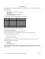
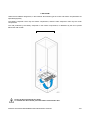
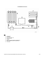
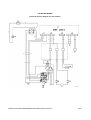
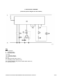
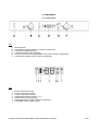
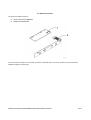
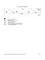
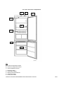
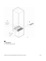
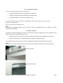
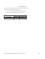
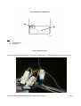
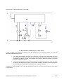
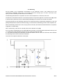
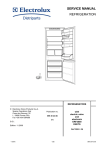
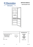
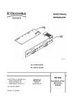
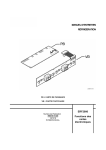
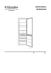
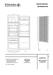
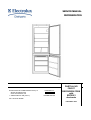
SERVICE MANUAL REFRIGERATION © ELECTROLUX HOME PRODUCTS S.p.A. Spares Operations Italy Corso Lino Zanussi, 30 I - 33080 PORCIA / PN (ITALY) Fax +39 0434 394096 Publication no. 599 37 38-00 051031 ITZ/SERVICE/AA PARTIAL NO FROST REFRIGERATORS with ERF2021 electronic FACTORY: HUY PARTIAL NO FROST REFRIGERATORS with ERF2021 electronic 2/41 TABLE OF CONTENTS 1. INTRODUCTION ..................................................................................................................................................4 2. AIR FLOW ............................................................................................................................................................6 3. REFRIGERATOR CIRCUIT .................................................................................................................................8 4. ELECTRIC WIRING .............................................................................................................................................9 5. FUNCTIONAL DIAGRAM ................................................................................................................................. 11 6. COMPONENTS ................................................................................................................................................. 12 6.1. Control panel............................................................................................................................................... 12 6.2. Electronic boards ........................................................................................................................................ 13 6.2.a. Power control board ERF2021................................................................................................................. 14 6.2.b. Display board ERF2000........................................................................................................................... 16 6.3. Cooler and freezer compartments .............................................................................................................. 17 6.3.a. Temperature sensors............................................................................................................................... 19 6.3.b. Door switches........................................................................................................................................... 19 6.3.c. Balancing heater ...................................................................................................................................... 20 6.3.d. Cold module fan....................................................................................................................................... 20 6.3.e. Defrosting heater ..................................................................................................................................... 20 6.3.f. Thermal switches ...................................................................................................................................... 21 6.4. Compressor compartment .......................................................................................................................... 22 6.4.a. Connections box ...................................................................................................................................... 22 7. OPERATION ..................................................................................................................................................... 23 7.1. Normal......................................................................................................................................................... 23 7.2. Normal with first switching on or power failure ........................................................................................... 24 7.3. Defrosting.................................................................................................................................................... 25 7.4. Flow chart for the defrosting management ................................................................................................. 26 7.5. SUPER function (rapid freezing)................................................................................................................. 27 7.6. SHOPPING Function (rapid cooling) .......................................................................................................... 27 7.7. Malfunctioning of cooler air temperature sensor......................................................................................... 29 7.8. Malfunctioning of freezer air temperature sensor ....................................................................................... 30 8. ALARM SIGNALLING....................................................................................................................................... 31 8.1. Freezer compartment temperature alarm ................................................................................................... 31 9. DEMO MODE .................................................................................................................................................... 32 9.1. Start DEMO MODE.................................................................................................................................... 32 9.2. Exit DEMO MODE ...................................................................................................................................... 32 9.3. Functions of the DEMO MODE................................................................................................................... 32 10. ACCESSIBILITY TO FREEZER COMPARTMENT........................................................................................ 34 10.1. Battery evaporator .................................................................................................................................... 34 11. ACCESSIBILITY TO CONTROL PANEL ....................................................................................................... 38 12. TROUBLESHOOTING .................................................................................................................................... 39 12.1. Excessive ice formation on the battery: .................................................................................................... 39 12.2. Failed defrosting: ...................................................................................................................................... 39 13. DISPLAY SYMBOLS ...................................................................................................................................... 40 PARTIAL NO FROST REFRIGERATORS with ERF2021 electronic 3/41 PARTIAL NO FROST REFRIGERATORS with ERF2021 electronic 4/41 1. INTRODUCTION This manual describes the Partial No Frost Refrigerators with ERF2021 electronic produced in the Nyíregyháza factory called HUY. These models feature: - Partial No Frost (no frost freezer, static refrigerator) Free standing single-compressor electronic controls (electronic board ERF2021) liquid crystal display (LCD) They are appliances (CBFF 340 e CBFF 380) with the following PNCs: PNC 925033001 925033002 925033004 925033041 925033042 925033201 925033203 925033229 925033230 MODEL ANB3450 ENB3450 ZNB3450 399.774-9/40800 ZKN3406 ENB3850 ZNB3850 974.027-5/40801 ZKN3806 BRAND Arthur Martin Electrolux Electrolux Zanussi-Electrolux Privileg Zanker Electrolux Zanussi-Electrolux Privileg Zanker The controls of the appliance are inserted into the work top. The power control board is ERF2021. The user interface board is ERF2000 (liquid crystal display LCD). Since it is a single-compressor, it is not possible to switch off only one of the two compartments. The temperatures regulation is the following: from +8 to +2 ° for the cooler from -16 to -22 °C for the freezer The LCD display enables to show not only the compartment temperatures but also the room temperature. The appliance has the following functions: rapid freezing rapid cooling freezer temperature alarm Moreover, since there is a balancing heater inside the appliance automatically actioned by the electronic board, it is not necessary that the user regulates the set temperatures for the freezer compartment when the room temperature is low. PARTIAL NO FROST REFRIGERATORS with ERF2021 electronic 5/41 The appliance consists of the following compartments: freezer; cooler; The evaporating circuit consists of cold module (freezer compartment); tube evaporator (refrigerator compartment). A Key: A = control panel B = cooler compartment C = cold module D = No Frost freezer compartment B C D PARTIAL NO FROST REFRIGERATORS with ERF2021 electronic 6/41 2. AIR FLOW Unlike the NO FROST refrigerators, in the PARTIAL NO FROST type the cooler and freezer compartments are separated physically. The battery evaporator cools only the freezer compartment, while the tube evaporator cools only the cooler compartment. The cold produced by the battery evaporator in the freezer compartment, is distributed by the fan C placed behind the cold module. AIR FLOW C In case of door opening the fan stops. To simulate the door closed, press the button of the freezer door. PARTIAL NO FROST REFRIGERATORS with ERF2021 electronic 7/41 PARTIAL NO FROST REFRIGERATORS with ERF2021 electronic 8/41 3. REFRIGERATOR CIRCUIT Key: 1. 2. 3. 4. 5. 6. 7. 8. compressor; condenser; anti-condensation coil; dehydrator filter; capillary; battery evaporator (freezer compartment); tube evaporator (cooler compartment); exchanger. PARTIAL NO FROST REFRIGERATORS with ERF2021 electronic 9/41 4. ELECTRIC WIRING (check the specific diagram for each model!) PARTIAL NO FROST REFRIGERATORS with ERF2021 electronic 10/41 Key: 2. 5. 9. 10. 13. 15. 16. 24. 26. 27. 28. 41. 56. 57. compressor motor protector defrosting heater balancing heater lamp cooler door switch freezer door switch fan safety thermal switch (+40°C) defrosting cut-out switch (+8°C) running capacitor (only for the models which feature it) electronic board cooler air temperature sensor (cable colour: brown) freezer air temperature sensor (cable colour: white) a. yellow-green; b. brown; c. blue; d. white; e. black; PARTIAL NO FROST REFRIGERATORS with ERF2021 electronic 11/41 5. FUNCTIONAL DIAGRAM (check the specific diagram for each model!) Key: 2. 5. 9. 13. 15. 16. 24. 26. 27. 28. 41. compressor motor protector defrosting heater lamp cooler door switch freezer door switch fan safety thermal switch (+40°C) defrosting cut-out switch (+8°C) running capacitor (only for the models which feature it) electronic board PARTIAL NO FROST REFRIGERATORS with ERF2021 electronic 12/41 6. COMPONENTS 6.1. Control panel Key: A. B. C. D. E. F. ON/OFF button; Temperature regulation knob of the freezer compartment; Temperature displaying button; Temperature and function displaying; Function activation button (temperature alarm reset of freezer compartment); Temperature regulation knob of cooler compartment; Key: 1. 2. 3. 4. 5. 6. 7. Room temperature symbol Cooler compartment symbol Freezer compartment symbol Temperature indicator (symbol – or +) SUPER function (rapid freezing) Temperature alarm symbol of freezer compartment SHOPPING function (rapid cooling) PARTIAL NO FROST REFRIGERATORS with ERF2021 electronic 13/41 6.2. Electronic boards The electronic board consists of: 1. power control board ERF2021 2. display board ERF2000 The two electronic boards are connected by means of a flat cable with a connector; therefore, the two boards are available singularly as spare part. PARTIAL NO FROST REFRIGERATORS with ERF2021 electronic 14/41 6.2.a. Power control board ERF2021 View of power board (components side): 1. 2. 3. 4. 5. line compressor neutral free balancing heater 1. 2. 3. 4. fan line fan neutral defrosting heater neutral defrosting heater line 1. 2. 3. 4. free free freezer door switch freezer door switch PARTIAL NO FROST REFRIGERATORS with ERF2021 electronic 15/41 1. 2. 3. 4. 5. 6. cooler air temperature sensor cooler air temperature sensor free free freezer air temperature sensor freezer air temperature sensor 1. 2. 3. 4. free free free free PARTIAL NO FROST REFRIGERATORS with ERF2021 electronic 16/41 6.2.b. Display board ERF2000 Key: SW1 SW2 SW3 SW4 LCD POT1 POT2 NTC1 = function activation button; = ON/OFF button; = temperature displaying button; = reed element (optional); = liquid crystal display; = freezer compartment temperature regulation; = cooler compartment temperature regulation; = room temperature sensor. PARTIAL NO FROST REFRIGERATORS with ERF2021 electronic 17/41 6.3. Cooler and freezer compartments 3 C 2 4 B 1 5 A Key: A = cooler air temperature sensor B = freezer air temperature sensor C = room temperature sensor 1 = balancing heater 2 = cooler door magnet 3 = display board reed element 4 = cooler door button 5 = freezer door button PARTIAL NO FROST REFRIGERATORS with ERF2021 electronic 18/41 7 8 6 Key: 6 = thermal switches 7 = cold module fan 8 = cold module defrosting heater PARTIAL NO FROST REFRIGERATORS with ERF2021 electronic 19/41 6.3.a. Temperature sensors 3 sensors are used to detect the various temperatures: cooler air temperature sensor A (located on the cooler cell) freezer air temperature sensor B (located on the freezer cell) room ambient sensor C (located on the display board) The wires leading from sensors A and B are encapsulated in foam inside the cabinet. As a result, these sensors are not replaceable. Sensor C is mounted on the display board. Note: The freezer air temperature sensor B is not used to control the appliance but only to display the freezer compartment temperature. 6.3.b. Door switches The battery evaporator defrosting is driven by the electronic board and depends also on the detection of the opening of the cooler and freezer door by using: magnetic switch for the cooler door control (located on the display board inserted into the work top) button for the freezer door control (located on the left side of the cold module). The magnetic switch for the cooler door control is activated by a magnet located inside the cooler door. Note: The cooler door button is located under the work top and controls only the switching on and off of the lamp. cooler door button freezer door button PARTIAL NO FROST REFRIGERATORS with ERF2021 electronic 20/41 6.3.c. Balancing heater The switching on of the balancing heater is controlled by the power control board and depends not only on the room temperature but also on the temperature settings of both compartments. The balancing heater is powered when the SUPER function is selected. The balancing heater is foamed inside the cabinet, therefore it is not replaceable. The balancing heater wires are connected inside the compressor junction box. The balancing heater has the following values: - power 16 W voltage 240 V resistance 3600 Ohm 6.3.d. Cold module fan The fan is located behind the cold module. The air is intaken by the fan, therefore, in case of its replacement, ensure that the air is forced towards the cell bottom. The fan has the following values: - voltage 240 V power 3,1 W speed 2000 rpm In case of door opening the fan stops. To simulate the door closed, press the button of the freezer door. 6.3.e. Defrosting heater The defrosting heater is used to defrost the ice that has accumulated on the battery evaporator. The defrosting heater has the following values: - power 235 W voltage 240 V resistance 245 Ohm PARTIAL NO FROST REFRIGERATORS with ERF2021 electronic 21/41 6.3.f. Thermal switches The thermal cut-outs are positioned in direct contact with the battery evaporator. They switch off the defrosting heater respectively at: +8 °C cut-out defrosting switch (wire colour: black - blue) +40 °C cut-out safety switch (wire colour: black - white) TYPE OF THERMAL OVERLOAD CUT-OUT DEFROSTING SAFETY CUT-IN TEMPERATURE OPENING CLOSING + 8 °C - 5 °C + 40 °C + 30 °C PARTIAL NO FROST REFRIGERATORS with ERF2021 electronic 22/41 6.4. Compressor compartment A B Key: A. connections box B. compressor 6.4.a. Connections box The connections box is located in the compressor compartment to connect the various electrical components. PARTIAL NO FROST REFRIGERATORS with ERF2021 electronic 23/41 7. OPERATION 7.1. Normal Warning: Disconnect the appliance from the electric power before operating with the appliance. In case of first switching on with a freezer compartment temperature higher than 10 °C, the appliance operates with a test cycle (for the factory) for a maximum time of about 1,5 hours. In this period do not check the correct functioning of the appliance, since the loads are activated only for internal check (compressor, fan, heaters) When the appliance is off then: the compressor is off the display is off Pushing down the ON/OFF button, the LCD display switches on with the following displaying: room temperature with the relative symbol; sign +; display with red background; freezer compartment temperature alarm (buzzer active). Push the function activation button to deactivate the buzzer sound. Position the knobs of the compartments on the upper green side so as to set the following temperatures: about +5 °C in the cooler; about -18 °C in the freezer. In NOFROST freezers, the humidity inside the freezer compartment accumulates on the evaporator battery thanks to the air circulation, thus preventing the formation of frost on food. During normal operation time the electronic board powers the compressor (2) and the fan (24) circuits. The operation of the fan is independent from the operation of the compressor (the fan is on only when the compressor is on). The fan is activated or deactivated with a 2 minute delay compared to the compressor. The operation time which corresponds to the interval between the following defrosting lasts about 14 hours with normal opening of the door (it can last up to 72 hours if the doors are never opened). PARTIAL NO FROST REFRIGERATORS with ERF2021 electronic 24/41 The arrows in the picture indicate the current path. 7.2. Normal with first switching on or power failure In case of fault when the appliance is switched on for the first time or in case of a power failure, one of the two conditions described below occurs: 1. If the internal temperature is higher or the same as the sensor cut-in temperature (CUT-IN), when the power is restored, the electronic board activates the compressor and the fan till the set temperature is reached and after 5 hours the electronic board activates the defrosting procedure (after the compressor cut-out). 2. If the internal temperature is lower than the sensor cut-in temperature (CUT-IN), when the power is restored, the compressor functions in thermostatic conditions and after 5 hours the electronic board activates the defrosting procedure (after the compressor cut-out). The electronic board activates, in any case, the defrosting procedure 5 hours after the first switching on and after a power failure. PARTIAL NO FROST REFRIGERATORS with ERF2021 electronic 25/41 7.3. Defrosting All the humidity in the compartment accumulates on the evaporator, which is the coldest part of the compartment; periodically, about every 14 hours with normal door opening (up to 72 hours if the doors never open!), it is then necessary to defrost the ice on the battery. The defrosting starts after the compressor cut-out or if the compressor is on after 2,5 hours max. The electronic board disconnects the circuit which powers the compressor (2) after 2 minutes the fan (24), waits 3 minutes then it powers the circuit of the defrosting heater (9) for a minimum time of about 20 minutes. The heat generated by the defrosting heater does not affect the freezer compartment temperature or the food packages temperature, because the thermal energy is consumed in the defrosting process of the evaporator ice. When the defrosting switch cuts-out and, anyway after 20 minutes, the electronic board switches the compressor on (2) with a 5 minute delay. After 3 minute delay, when the air is already cold, the fan switches on too (24). If for any reason, the defrosting cut-out switch (27) does not switch on and the battery temperature rises up to 40 °C, the defrosting heater (9) will be switched off by the safety thermal switch (26). If 1 hour after the starting of the defrosting, the thermal switches did not cut out, the electronic board switches the defrosting heater off and continues its operation. The arrows in the picture indicate the current path. PARTIAL NO FROST REFRIGERATORS with ERF2021 electronic 26/41 START 7.4. Flow chart for management NO More than 5 h elapsed after power on & compressor off or compressor on for more than 2,5 h? the defrosting YES DEFROSTING Resetting door accumulated timer SUPER freezing activated YES More than 14 h elapsed after the last defrosting? NO NO YES DEFROSTING More than 14 h elapsed after the last defrosting & cooler or freezer door is open? YES NO More than 14 h elapsed after the last defrosting & comp on for more than 2,5 h? YES NO More than 30 h elapsed after the last defrosting & cooler or freezer door is open? YES NO More than 72 h elapsed after the last defrosting? YES NO DEFROSTING PARTIAL NO FROST REFRIGERATORS with ERF2021 electronic 27/41 NOTE #: When the cooler or freezer door is open it means that one of the two doors is opened for more than 1 minute. At every defrosting the time is resetted. 7.5. SUPER function (rapid freezing) The SUPER function (rapid freezing) is activated by pushing the activation function button till the symbol appears, therefore: the symbol corresponding to SUPER function is displayed; the compressor operates in thermostatic conditions and not continuously (like the temperature knob was on max. position) for a duration of about 52 hours, and then it deactivates automatically. To deactivate the SUPER function, push the function activation button till the symbol disappears. With the SUPER function the balancing heater is powered. With the SUPER function the fixed defrosting can occur anyway depending on how much time is elapsed after the last defrosting. 7.6. SHOPPING Function (rapid cooling) The SHOPPING function (rapid cooling) is activated by pushing the function activation button till the symbol appears, therefore: the symbol corresponding to SHOPPING function is displayed; the compressor operates in thermostatic conditions and not continuously (like the temperature knob was on max. position) for a duration of about 6 hours, and then it deactivates automatically. To deactivate the SHOPPING function, push the function activation button till the symbol PARTIAL NO FROST REFRIGERATORS with ERF2021 electronic disappears. 28/41 PARTIAL NO FROST REFRIGERATORS with ERF2021 electronic 29/41 7.7. Malfunctioning of cooler air temperature sensor If during the normal operation a failure occurs to the cooler air temperature sensor (the signal coming from the sensor is out of range), therefore pushing the function activation button: The display shows cooler temperature sensor faulty The appliance operates with preset cycle where the compressor is powered for 40 minutes and remains off for 40 minutes alternatively The defrosting procedure is activated every about 14 hours When the sensor operates again normally, the above described conditions terminate. Characteristics of the NTC sensor: PARTIAL NO FROST REFRIGERATORS with ERF2021 electronic 30/41 7.8. Malfunctioning of freezer air temperature sensor If during the normal operation a failure occurs to the freezer air temperature sensor (the signal coming from the sensor is out of range), therefore pushing the function activation button: The display shows freezer temperature sensor faulty. The appliance operates normally. The freezer air temperature sensor is not used to control the appliance but only to display the freezer compartment temperature. Characteristics of the NTC sensor: PARTIAL NO FROST REFRIGERATORS with ERF2021 electronic 31/41 8. ALARM SIGNALLING 8.1. Freezer compartment temperature alarm When the freezer compartment reaches -11 °C, the temperature alarm activates: The LCD display becomes red; The symbol The buzzer sounds. is displayed; Push the function activation button to deactivate the buzzer. When normal conditions are reset (after a power failure): The acoustic signal deactivates; The symbol The lighting of the display remains red. remains lit; Pushing the function activation button: The highest temperature reached in the freezer compartment is displayed for 5 minutes; The symbol The red lighting of the display switches off. switches off; PARTIAL NO FROST REFRIGERATORS with ERF2021 electronic 32/41 9. DEMO MODE The DEMO MODE function is intended only for the commercial activity and not for the user. The internal temperature of the appliance, measured by the air sensors, must be higher than +10 °C, so as the function can be activated. 9.1. Start DEMO MODE To start the procedure, hold down the temperature display button for more than 5 seconds. The display background becomes dark blue and the room temperature value flashes. 9.2. Exit DEMO MODE To exit the procedure, hold down the temperature display button for more than 5 seconds or unplug the appliance. 9.3. Functions of the DEMO MODE The procedure is used only to show in the selling points and allows selecting the temperatures without activating the loads (compressor, fan, heaters). Pressing the temperature display button, the display shows: + 5 °C for the cooler compartment (flashing display) -18 °C for the freezer compartment (flashing display) By rotating the temperature regulation knobs, the display shows the set temperatures (flashing display). The internal light switches on when the cooler door is opened. PARTIAL NO FROST REFRIGERATORS with ERF2021 electronic 33/41 PARTIAL NO FROST REFRIGERATORS with ERF2021 electronic 34/41 10. ACCESSIBILITY TO FREEZER COMPARTMENT 10.1. Battery evaporator To access the battery evaporator and its components (fan, defrosting heater, door switch, and thermal switches) perform the following operations in sequence: a) remove the freezer drawers b) detach the fan and defrosting heater connectors located inside the connections box (compressor compartment) c) cut the wiring tie d) lean the appliance on the rear side (condenser side) e) insert a screwdriver into the right hook and release it F f) insert a blade inside the F slot and release the internal hook g) view of the internal hook PARTIAL NO FROST REFRIGERATORS with ERF2021 electronic 35/41 h) lift and pull the ventilation grid i) unscrew the 2 fixing screws of the air diffuser l) cut the air diffuser pulling and lifting it up m) unscrew the 2 fixing screws of the cold module n) pull backward the cold module support releasing the rear water drain duct o) view of the rear water drain duct PARTIAL NO FROST REFRIGERATORS with ERF2021 electronic 36/41 p) release the left hook of the defrosting heater q) release the right hook of the defrosting heater r) cut the wiring tie of the thermal switches and release them from the evaporator Note: s) remove the sealing rubber The defrosting and cut-out thermal switches (+8 /+40°C) are connected together, therefore they are not available as single spare parts. PARTIAL NO FROST REFRIGERATORS with ERF2021 electronic 37/41 t) remove the wiring fixing tie u) unplug the connector of the thermal switches v) the heater is fitted to the evaporator by means of the aluminium ties w) remove the fan extracting it from the evaporator support In case of replacement of the fan, it is necessary to ensure that the fan draws in air. x) to remove the freezer door switch y) release the door button hook and simultaneously pull it backward PARTIAL NO FROST REFRIGERATORS with ERF2021 electronic 38/41 11. ACCESSIBILITY TO CONTROL PANEL To access the control panel and its components (power/display boards, cooler switches and electric connectors) perform the following operations: a) unscrew the 2 fixing screws of the control panel locating under the upper hinges b) release the 2 hooks of the control panel inserting a screwdriver into both its sides c) pull backward the control panel d) it is possible to access the main switch and the electronic board connectors e) view of the electronic board connectors PARTIAL NO FROST REFRIGERATORS with ERF2021 electronic 39/41 12. TROUBLESHOOTING WARNING! Switch off the power to the appliance before operating. 12.1. Excessive ice formation on the battery: If the rubber valve remains open, the humid air outside the freezer compartment is ducted inside and it accumulates too much ice on the battery. The valve remains open if there are foreign bodies or if it looses elasticity; therefore, in the first case the foreign bodies must be removed, while in the latter the rubber valve must be replaced. 12.2. Failed defrosting: In case of failed defrosting, the possible causes are: Sequence n° 1 POSSIBLE CAUSES The defrosting heater is interrupted 2 One or both switches of the thermal protectors are open HOW TO CONTROL HOW TO CONTROL Unplug the appliance, remove the connector of the heater and verify with the tester the correct resistance value to the connector clamps Frost the battery, then detach the power plug of the appliance, remove the connector of the thermal switches and verify with the tester the correct resistance value to the connector clamps If the resistance value does not correspond to the technical data, replace the heater PARTIAL NO FROST REFRIGERATORS with ERF2021 electronic If the resistance value does not correspond to 0 (zero Ohm) replace the thermal switches 40/41 13. DISPLAY SYMBOLS DISPLAY DIGITS DESCRIPTION NOT FLASHING It indicates the room temperature with normal function FLASHING It indicates the room temperature with DEMO MODE function NOT FLASHING It indicates the cooler temperature with normal function [from +2 to +8] FLASHING It indicates the cooler temperature with DEMO MODE function [from +2 to +8] NOT FLASHING It indicates the freezer temperature with normal function [from -16 to -22] FLASHING It indicates the freezer temperature with DEMO MODE function [from -16 to -22] NOT FLASHING It indicates the cooler temperature with SHOPPING function NOT FLASHING It indicates the freezer temperature with SUPER function NOT FLASHING It indicates the freezer temperature with ALARM function NOT FLASHING It indicates the malfunctioning of cooler air temperature sensor NOT FLASHING It indicates the malfunctioning of freezer air temperature sensor NOT FLASHING NOT FLASHING It indicates incompatibility between the electronic boards. Remedy: check the spare part nos. of the electronic boards It indicates eeprom parameter writing/reading error. Remedy: replace both electronic boards (power and display) PARTIAL NO FROST REFRIGERATORS with ERF2021 electronic 41/41