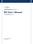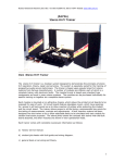
1
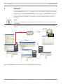
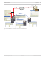
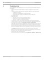
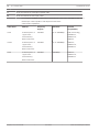
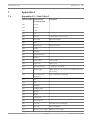
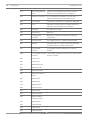
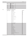
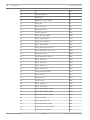
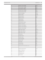
FPA-5000 OPC-Server
FSM-5000-OPC
en
User Guide
FPA-5000 OPC-Server
Table of Contents | en
3
Table of contents
1
Purpose
4
2
Preconditions
6
3
Installation
7
3.1
Installation of FSM-5000-OPC Software
7
3.2
Remote Access to the FSM-5000-OPC Server from the Building Integration System (BIS)
7
3.3
Backward Compatibility
9
3.3.1
Package: BIS600StateConversion.msi
9
3.3.2
Package: LanguageDependentCommand.msi
4
Step-by-Step Configuration
10
4.1
FSP-5000-RPS
10
4.2
Panel Controller MPC-xxxx-B or MPC-xxxx-C
11
4.3
PC/Server
11
5
Troubleshooting
12
6
Technical data
13
7
Appendices
15
7.1
Appendix A.1 - State Table 1
15
7.2
Appendix A.2 - State Table 2
17
Bosch Sicherheitssysteme GmbH
User Guide
9
2013/05 | 2.0 | F.01U.261.550
4
1
en | Purpose
FPA-5000 OPC-Server
Purpose
This document contains information on accessing and controlling FPA-5000 networks via OPC
using the FSM-5000-OPC server. It is designed to aid in successfully configuring the FPA-5000
network and the corresponding FSM-5000-OPC server to enable communication between the
two via a single or redundant Ethernet connection. In completing these steps successfully a
functional interface is provided for a subsequent connection to BIS 2.x which functions as
OPC client.
Notice!
Setting up and configuring an FPA-5000 network controlled by an OPC server requires basic
IT knowledge.
The information refers to FSM-5000-OPC Version 1.1.11 and later and supported FPA-5000
software.
192.168.1.2
255.255.255.0
Cat. 5
Cat. 5
Ethernet
FPA_OPC
RSN 004
CAN
RSN 001
RSN 002
RSN 003
RSN 003
Figure 1.1: FPA-5000 network controlled by an OPC server with single Ethernet connection
2013/05 | 2.0 | F.01U.261.550
User Guide
Bosch Sicherheitssysteme GmbH
FPA-5000 OPC-Server
Purpose | en
5
192.168.1.2
255.255.255.0
Cat. 5
Cat. 5
Ethernet
FPA_OPC
RSN 004
switch
CAN
RSN 001
RSN 002
RSN 001
RSN 003
RSN 003
Figure 1.2: FPA-5000 network controlled by an OPC server with redundant panel
Bosch Sicherheitssysteme GmbH
User Guide
2013/05 | 2.0 | F.01U.261.550
6
2
en | Preconditions
FPA-5000 OPC-Server
Preconditions
The following must be available to set up an OPC server in an FPA-5000 network:
–
FPA-5000 network with MPC-xxxx-B or MPC-xxxx-C
–
ADC-5000-OPC license card
–
Latest FSP-5000-RPS installation CD
–
The correct FSM-5000-OPC Server version for the respective FPA-5000 release (available
on FSP-5000-RPS installation CD or download from Extranet). Look up the compatible
version in the readme file of the FSM-5000-OPC software.
–
Existing Ethernet network with Cat. 5e cable
–
PC to install FSM-5000-OPC on
2013/05 | 2.0 | F.01U.261.550
User Guide
Bosch Sicherheitssysteme GmbH
FPA-5000 OPC-Server
Installation | en
3
Installation
3.1
Installation of FSM-5000-OPC Software
7
Task: FSM-5000-OPC is running on a PC.
Notice!
.NET Framework 2.0 must be installed to run FSM-5000-OPC. If it is not present install it from
the Pre-Requisites folder of the FSP-5000-RPS installation CD or download it from http://
www.microsoft.com/downloads/en/default.aspx
1.
On the setup disc open the folder that contains the FSM-5000-OPC installation.
2.
Click “FPA5000OPCServer.msi” and follow the installation instructions.
3.
Open the Configuration Editor:
Start → All Programs → Bosch → FPA5000OPC-Server and run Configuration Editor
or open Windows Explorer, navigate to
C:\Program Files\Bosch\FPA 5000OPC-Server and run ConfigEditor.exe
or for FSM-5000-OPC version 1.2 right click on the respective icon in the taskbar
notification area and choose “Configuration”.
4.
Under the “Communications“ tab adopt the settings that were entered for the node
“FPA5000 OPC Server” in the RPS configuration.
5.
Configure the Windows firewall. The configuration depends on the operating system and
6.
Restart the system.
the used firewall.
FSM-5000-OPC will be running after restart, indicated by a notification icon in the taskbar
notification area.
Notice!
The installation of FSM-5000-OPC is only released for the Windows operating systems listed
in Technical data, page 13. For other operating systems the installation may succeed but
was not tested and is therefore on your own risk.
3.2
Remote Access to the FSM-5000-OPC Server from the Building
Integration System (BIS)
Task: FSM-5000-OPC is running on a PC in your local network interconnected with the panel
network. The OPC client application runs on a PC of the Building Integration System (BIS) in
the same local network. It remotely accesses the FSM-5000-OPC server.
Server side PC
Notice!
Consider the naming conventions for users, groups and passwords (“MgtS-Service”
“BISUsers“) given in this description. The Building Integration System (BIS) internally makes
use of these conventions. As BIS internally always assumes the same user and password by
convention it is not necessary to logon as a distinct user or enter the password. If you
remotely access the FSM-5000-OPC server with another client, you are free to choose names
and a password on the server side, as long as you specify the matching logon when your
client connects to the OPC server.
Bosch Sicherheitssysteme GmbH
User Guide
2013/05 | 2.0 | F.01U.261.550
8
en | Installation
FPA-5000 OPC-Server
All of the following settings refer to the PC running the OPC server.
Notice!
The following steps are based on the Windows XP operating system. For all other operating
systems the paths to the respective dialogs might be slightly different.
Create user „MgtS-Service“ manually
1. Go to Start – Settings – Control Panel – Administrative Tools – Computer Management
– Local Users and Groups – Users and enter the following values:
2.
–
Username (case sensitive): "MgtS-Service"
–
Password: Please contact BIS customer support if it is the BIS client you are using.
–
Member of group: Administrators
–
User must change password at next logon: NO
–
User cannot change password: YES
–
Password never expires: YES
Tab Local Security Settings:
–
Log on as a service: YES
–
Log on as a batch job: YES
Notice!
The user name and password must be identical with the user of the login server.
Create group BISUsers manually
1. Go to Start – Settings – Control Panel – Administrative Tools – Computer Management
– Local Users and Groups – Groups and enter the following value:
–
Group name (case sensitive): "BISUsers"
2.
Add the user “MgtS-Service” to that group
3.
Add the user who logs in from the operating system of the login server and who operates
the ConfigurationBrowser to that group too.
DCOM-Settings for the group BISUsers
1. Click Start > Run....
2.
Type dcomcnfg <ENTER>.
3.
Open the tree on the left side: Console Root > Component Services > Computers > My
Computer.
4.
Right click on My Computer and choose Properties.
5.
Choose the COM Security tab.
6.
Add the new group “BISUsers” by using Access Permissions – Edit Defaults – allow
Local and Remote Access.
7.
Add the new group “BISUsers” by using Launch and Activation Permissions – Edit
Defaults – allow Local and Remote Launch and allow Local and Remote Activation.
8.
Add the new group “BISUsers” by using Launch and Activation Permissions – Edit Limits
– allow Local and Remote Launch and allow Local and Remote Activation.
9.
Reboot the PC.
Set Local Security Policy
Perform the following procedure to set the Local Security Policy.
For operating systems Windows XP / Windows Server 2003 / Windows 7 / Windows Server
2008:
1.
Go to Start - Control Panel - Administrative Tools, and select Local Security Policy.
2.
Open the tree on the left side: Security Settings - Local Policies- Security Options.
2013/05 | 2.0 | F.01U.261.550
User Guide
Bosch Sicherheitssysteme GmbH
FPA-5000 OPC-Server
Installation | en
9
3.
Select on the right side: Network access: Sharing and security model for local accounts.
4.
Right click on this selection to open Properties and choose Classic– local users
authenticate as themselves.
5.
Close all windows and restart the PC.
6.
Open dcomcnfg and go to services (Local).
7.
Select FPA5000OPCServer - Properties and open the Log-On tab
8.
Choose radio button This Account – User: MgtS-Service and the password.
9.
You are requested to restart the service in order to activate the changes. Select Stop and
Start (or Restart).
Client side PC
On the PC running the FSM-5000-OPC client software connect to the server with the same
logon you used to start the service. This also applies if you install both on the same PC. The
OPC server installation routine installs the service for the local system account by default.
Change the service to “MgtS-Service” when you use the OPC server with BIS.
3.3
Backward Compatibility
There are two setup packages to provide backward compatibility.
To install the respective file
1.
Go to the Compatibility folder on the setup disk
2.
Double click the respective msi-file
Notice!
Only use these packages if you require compatibility with solutions designed for versions
prior to version 1.1 of FSM-5000-OPC server.
3.3.1
Package: BIS600StateConversion.msi
Description: States of the OPC server mapped to an offset of 600 instead of line status
designed for backward compatibility of OPC Server version 1.1 with older clients. For instance
configurations read by BIS 1.0.x requires it in order to work with the 1.1.x OPC Server.
Precondition: OPC Server ≥ 1.1.x installed.
Postcondition: Registry entry for OPC configuration set.
3.3.2
Package: LanguageDependentCommand.msi
Description: The commands are language dependent like OPC Server 1.0.x. Designed for
backward compatibility of OPC Server version 1.1 with older clients. For instance
configurations read by BIS 1.0.x requires it in order to work with the 1.1.x OPC Server.
Precondition: OPC Server ≥ 1.1.x installed
Postcondition: Registry entry for OPC configuration set.
Bosch Sicherheitssysteme GmbH
User Guide
2013/05 | 2.0 | F.01U.261.550
10
en | Step-by-Step Configuration
FPA-5000 OPC-Server
4
Step-by-Step Configuration
4.1
FSP-5000-RPS
1.
Open the FSP-5000-RPS programming software.
2.
In an existing 2.x configuration select “Nodes” in the tree view and choose “Create
FPA-5000 OPC- Server” in the context menu.
A new node with name FPA-5000 OPC-Server is created and a dialog box for configuration
is opened.
3.
Configure the OPC server node.
Enter the virtual RSN and logical node.
4.
Choose IP Settings... to enter the IP settings dialog.
5.
Edit the fields accordingly. IP Address and Subnet Mask are mandatory fields, Gateway
is optional.
Notice!
The settings must match the network adapter/card settings of the computer the FSM-5000OPC Server will be installed on!
The values of Net Group and Node Address, the RSN and the IP address are required to
configure the OPC server.
6.
Confirm your changes with OK and leave the dialog.
7.
Double-click on the FPA-5000 panel node that will be physically connected to the
Ethernet.
A dialog box for configuration opens.
8.
Choose IP Settings... to enter the IP settings dialog.
9.
Edit the fields accordingly. Panels not directly connected to the Ethernet are not assigned
an IP address.
10. Confirm your changes with OK and leave the dialog.
11. Double-click on the “FPA-5000” node, e.g. “FPA 5000 – 1.1 – RSN
A dialog box for FPA-5000 additional configuration opens
12. Select OPC Server under a vacant Inserted address card(s) field.
Notice!
It is mandatory that this FPA-5000 node is then assigned to the OPC server!
13. Choose the country and the language from the list
Notice!
Take care about the country and language settings. BIS 2.x will display commands and
detector names in the selected language.
14. Confirm your settings with OK and leave the dialog.
15. Double click on Assigned servers.
A dialog box opens.
16. Assign the panel to the OPC server. Repeat this task for each node that is to transmit its
states to the OPC server.
17. Confirm your changes with OK and leave the dialog.
2013/05 | 2.0 | F.01U.261.550
User Guide
Bosch Sicherheitssysteme GmbH
FPA-5000 OPC-Server
4.2
Step-by-Step Configuration | en
11
Panel Controller MPC-xxxx-B or MPC-xxxx-C
1.
Insert the ADC-5000-OPC card into one of the vacant address card slots.
2.
Go to the node that has been assigned an IP address and connect the Cat.-5 cable to the
MPC‑xxxx‑B or MPC‑xxxx‑C “Ethernet” port (RJ45).
4.3
PC/Server
1.
Connect the Cat.-5 cable to the PC Ethernet port. Afterwards open the DOS command
window and successfully “ping” the panel controller.
2.
Right click on the OPC icon in the taskbar notification area and open the Connection
dialog. A list with all identified panels and their respective connection status is displayed.
If the configuration was successful, all panels which are assigned to the OPC server
should have the status “connected”.
You can also find these information in a log file, located on C:\Program Files\Bosch
\FPA5000 OPC-Server\Log (for Windows XP, might be slightly different for other
operating systems).
Bosch Sicherheitssysteme GmbH
User Guide
2013/05 | 2.0 | F.01U.261.550
12
5
en | Troubleshooting
FPA-5000 OPC-Server
Troubleshooting
If the configuration of the FSM-5000-OPC server doesn’t work with the FPA-5000 network try
the following:
–
Confirm on the panel controller that the IP address is assigned and “ping” the OPC
server.
–
If the Ping request is answered but the configuration still doesn’t work please check
–
all settings on the panel,
–
all settings in the FSM-5000-OPC Configuration Editor,
–
the Ethernet adapter settings in the Window’s System Configuration.
–
De-activate firewall
–
Follow these steps:
–
–
Stop OPC (see “Service” tab in Configuration Editor)
–
Delete bin file(s) under C:\MPOPCServer\Repository
–
Start OPC → A new file per node will be created.
If no elements are shown, check whether the Repository folder exists and whether it
contains a bin file for each node. The files are located under C:\MPOPCServer\Repository.
–
On the MPC panel controller go to Diagnostics – Network – Routing table.
A table with routing information is displayed. All networked nodes that can be reached via
the panel and that are recognized within the system network are displayed under Node.
Aside the respective interfaces via which the connected network nodes are connected to
the panel are displayed. If the OPC server configuration is correct there must be an entry
under Node with the RSN of the OPC server node and the interface “UDP tunnel”.
–
Make sure that the panel controller does not show any troubles which could concern the
OPC server node or the network communication in general.
–
Verify that OPC card is detected by panel:
Choose in the start menu of the panel controller: Diagnostics - Hardware - Address cards
2013/05 | 2.0 | F.01U.261.550
User Guide
Bosch Sicherheitssysteme GmbH
FPA-5000 OPC-Server
Technical data | en
13
Technical data
6
Supported OPC standards:
–
DA 2.0
–
AE 1.01
Other Standards
–
“BIS Common Requirements” (Bosch standard).
Supported operating systems:
–
Windows XP Professional
–
Windows 2003 Server 32-bit
–
Windows 2008 Server 64-bit
–
Windows 2008 Server R2 64-bit
–
Windows 7 32-bit
–
Windows 7 64-bit
Limits
For each panel approximately 2000 OPC items can be created in maximum configuration.
Memory
For configuration data caching a file with approximately 200kb is stored for each panel in the
repository folder.
Licensing
Each OPC Server requires an OPC license card (ADC-5000-OPC) in one of the assigned
FPA-5000 panels.
Additional Information
LAN Technology Specifications:
IEEE Standard
Name
Data Rate
Media Type
Maximum
Distance
Ethernet
802.3
10 Mbps
10Base-T
100 meters
Fast Ethernet/
8ß2.3u
100 Mbps
100Base-TX
100 meters 2000
100Base-FX
meters
1000Base-T
100 meters
1000Base-SX
275/550 meters
1000Base-LX
550/5000 meters
10GBase-SR
300 meters
10GBase-LX4
300m MMF/ 10km
10GBase-LR/ER
SMF
10GBase-
10km/40km
SW/LW/EW
300m/10km/40km
100Base-T
Gigabit Ethernet/
802.3z
1000 Mbps
GigE
10 Gigabit
IEEE 802.3ae
10 Gbps
Ethernet
Guide to Ethernet Coding
10
at the beginning means the network operates at 10Mbps.
BASE
means the type of signaling used is baseband.
2 or 5
at the end indicates the maximum cable length in meters.
T
at the end stands for twisted-pair cable.
Bosch Sicherheitssysteme GmbH
User Guide
2013/05 | 2.0 | F.01U.261.550
14
en | Technical data
FPA-5000 OPC-Server
X
at the end stands for full duplex-capable cable.
FL
at the end stands for fiber optic cable.
For example: 100BASE-TX indicates a Fast Ethernet connection (100 Mbps) that uses a
twisted pair cable capable of full-duplex transmissions.
Cable Grade Capabilities
Cable Name
Makeup
Frequency
Data Rate
Support
Cat-5
Cat-5e
4 twisted pairs of
Network
Compatibility
100 MHz
Up to 1000Mbps
ATM, Token Ring,
copper wire --
1000Base-T,
terminated by
100Base-TX,
RJ45 connectors
10Base-T
4 twisted pairs of
100 MHz
Up to 1000Mbps
10Base-T,
copper wire --
100Base-TX,
terminated by
1000Base-T
RJ45 connectors
Cat-6
4 twisted pairs of
250 MHz
1000Mbps
10Base-T,
copper wire --
100Base-TX,
terminated by
1000Base-T
RJ45 connectors
2013/05 | 2.0 | F.01U.261.550
User Guide
Bosch Sicherheitssysteme GmbH
FPA-5000 OPC-Server
Appendices | en
7
Appendices
7.1
Appendix A.1 - State Table 1
OPC Item Value Internal Panel
15
Description
Compound State
600
Invalid
601
Normal
602
Fault
603
Fire
604
Fire Pre
1st state AND / Cross zoning
605
Fire verify
Alarm Verification
606
Heat
607
Supervisory
608
Smoke
609
Activate
610
Activation failed
611
Tamper
612
Cover open
Cover is open
613
Paper out
Paper is out
614
Threshhold Alarm
1st stage fire, threshold
615
Trouble light
Light trouble, e.g. C-Sensor of a combined detector
Supervisory Error
not working
616
Panel Restart by
Panel restarted by watchdog
Watchdog
617
On
618
Off
619
Pollution
620
Pollution light
621
Monitor
622
Water
623
Power Fail
624
Manual Alarm
625
Fire PAS
PAS (Wait for acknowledge)
626
Fire PAS
PAS (Investigate)
627
Address card change
Address card changed
Bosch Sicherheitssysteme GmbH
User Guide
2013/05 | 2.0 | F.01U.261.550
16
en | Appendices
FPA-5000 OPC-Server
628
629
Not enough address
Address card changed and now there are less
space
addresses licensed than points configured
Address card tamper
The countdown after address card removal is
finished, addresses are to be switched off
630
Fire internal
Internal fire, results from a usage type “FIRE_INT”
631
Error
Indicates an invalid value for a logical state since
INVALID is used elsewhere in the system
632
Unknown
For state stor use only
633
internal use
Wild card
634
Configuration
Mismatch of network configuration (topology
mismatch
information)
635
Unknown item
Unconfigured item i.e. network node detected
636
Missing
Configured item i.e. network node NOT detected,
for internal items currently trouble used
637
638
Incompatible
Incompatible software detected for nodes in
software
network
Incompatible network Incompatible network protocol version detected for
protocol
nodes in network
639
internal use
640
internal use
641
Walktest Normal
642
Walktest Fault
643
Walktest Activate
644
Walktest Activation
failed
645
Walktest On
646
Walktest Off
647
Walktest Alarm
648
Bypass Normal
649
Bypass Fault
650
Bypass Activate
651
Bypass Isolated
Activation failed
652
Bypass Alarm
653
Isolate Normal
654
Isolate Fault
655
Isolate Activate
2013/05 | 2.0 | F.01U.261.550
User Guide
Bosch Sicherheitssysteme GmbH
FPA-5000 OPC-Server
Appendices | en
656
17
Isolate Activation
failed
657
Isolate Alarm
658
Normal Day Mode
659
Fault Day Mode
660
Alarm Day Mode
Table 7.1: Appendix A.1 - State Table 1
7.2
Appendix A.2 - State Table 2
OPC Item Value
Description
LZ Name
0
Missing Zone
FG
1
Detector masking
MAD
2
Fade-out/Skip
ABL
3
Zone switch off
ABS
4
Detector test
TST
5
Stand-by/Control off
GE
6
Breakdonw centr. part
G8
7
Control On
STE
8
Malfunction ground
ES
9
Criterion -4
K4
10
Criterion -3
K3
11
Criterion -2
K2
12
Malfunction generic
G0
13
Emergency alarm
H1
14
Int-Fire
F3
15
Pre-Fire
F2
16
Ext-Fire (TU)
F1
17
Trigger disarmed
A6
18
Intern-Alarm
A5
19
Int-Sabotage
A4
20
Ext-Sabotage (TU)
A3
21
Ext-Intrusion (TU)
A2
22
Hold-up Alarm (TU)
A1
23
Ext-Malfunction.(TU)/Ext-Fire. (TU)
A0
24
Stand-by/Off
PE
Bosch Sicherheitssysteme GmbH
User Guide
2013/05 | 2.0 | F.01U.261.550
18
en | Appendices
FPA-5000 OPC-Server
25
On
P2
26
Acknowledgement
P3
27
Malfunction
P4
28
Malfunction power supply
P5
29
Switch Off
P6
30
Alarm verification
TEL
31
Address Blocking
ASP
32
Triggering generic
R-FG
33
Maint.-Stand-by OMM
R-GE
34
Maint.-Light Pollution
R-G0
35
Maint.-Heavy Pollution
R-G2
36
Maint.-Alarm OMM
R-AL
37
Maint.-Stand-by/Control Off
R-GE
38
Maint.-Breakdown Centr. Part
R-G8
39
Maint.-Control On
R-STE
40
Maint.-Malfunction Ground
R-ES
41
Maint.-Criterion-4
R-K4
42
Maint.-Criterion -3
R-K3
43
Maint.-Criterion -2
R-K2
44
Maint.-Malfunction
R-G0
45
Maint.-Emergency Alarm
R-H1
46
Maint.-Int-Fire
R-F3
47
Maint.-Pre-Fire
R-F2
48
Maint.-Ext-Fire
R-F1
49
Maint.-Triggering
R-A6
50
Maint.-Intern Alarm
R-A5
51
Maint.-Alarm Thermo (UGM)
R-A4
52
Maint.-Alarm Optics (UGM)
R-A3
53
Maint.-Ext-Intrusion (UGM)
R-A2
54
Pollution (UGM)
R-A1
55
Maint.-Malfunction-Ext
R-A0
56
Stand-by R-R/Max (UGM)
R-PE
57
Stand-by ThermoMax (UGM)
R-P2
58
Stand-by Optics (UGM)
R-P3
2013/05 | 2.0 | F.01U.261.550
User Guide
Bosch Sicherheitssysteme GmbH
FPA-5000 OPC-Server
Appendices | en
59
Alarm Pre-Level (UGM)
R-P4
60
Fire-Int Thermo (UGM)
R-P5
61
Fire-Int Optics (UGM)
R-P6
62
Fire-Ext Thermo (UGM)
R-TEL
63
Fire-Ext Optics (UGM)
R-ASP
64
Stand-by R-R/Max
GE-TD
65
Stand-by TMax
GE-TM
66
Stand-by Optics
GE-O
67
Stand-by Combi
GE-K
68
Light Pollution
V2
69
Heavy Pollution
V1
70
Heavy Pollution (Qty.)
V0
71
Alarm Pre-Level Ion
AV-I
72
Alarm Pre-Level Optics
AV-O
73
Alarm Pre-Level Thermo
AV-T
74
Alarm Pre-Level Combi
AV-K
75
Maint.-Alarm Optics
R-F1-O
76
Maint.-Alarm Thermo
R-F1-T
77
Maint.-Alarm Combi
R-F1-K
78
Fire-Ext Opt
F1-O
79
Fire-Ext Thermo
F1-T
80
Fire-Ext Combi
F1-K
81
Call Fire Brigade
FWR
82
Fire-Pre (TU)
F2-E
83
Fire-Int Opt
F3-O
84
Fire-Int Therm
F3-T
85
Fire-Int Combi
F3-K
86
Hold-up alarm with menace (TU)
A1-B
88
Stand-by Day/Internal
T-GE
89
Periph. Control On
P8
90
Light Malfunction
G1
91
Line Malfunction
G2
92
End of Paper
PA
19
87
Bosch Sicherheitssysteme GmbH
User Guide
2013/05 | 2.0 | F.01U.261.550
20
en | Appendices
FPA-5000 OPC-Server
93
Triggering Disarmed
A7
94
Mains
Fault
95
Battery
Fault
Table 7.2: Appendix A.2 - State Table 2
2013/05 | 2.0 | F.01U.261.550
User Guide
Bosch Sicherheitssysteme GmbH
Bosch Sicherheitssysteme GmbH
Robert-Bosch-Ring 5
85630 Grasbrunn
Germany
www.boschsecurity.com
© Bosch Sicherheitssysteme GmbH, 2013