1
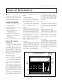
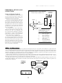
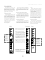
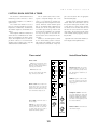
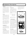
RADIO CONSOLE PRODUCTS
X- IXER
Digital Broadcast
Console
Technical Manual
July 1, 2008
X-mixer-14-14
X-mixer-14-22
ARRAKIS
advancedradio
Table of Contents
GENERAL INFORMATION
Console Overview ....................
Feature Descriptions ................
Specifications ...........................
Warranty ...................................
3
3
4
4
INSTALLATION
Console Configuration ..............
Grounding & Shielding ..............
Cabling & Wiring........................
Wire Preparation ......................
Crimp Tool Operation ...............
Analog Audio Connections ......
Digital Audio Connections ........
Peripheral Device Logic............
Misc Logic Connections............
Misc Console Connections ......
DIP switch Settings...................
Trim Pot Adjustments................
Connection Summary Dgm......
PC Setup Software...................
5
5
6
6
6
7
8
9
10
11
12
13
14
15-17
X-MIXER OPERATION
Input Channels .........................
Telco Channel...........................
Monitor Controls .......................
Timer Controls ..........................
Remote Line Selector ...............
Meter Housing...........................
T H E
EQUIPMENT DESCRIPTION
Chassis........................................
Motherboard................................
Option Board ..............................
Power Supply .............................
VU Meter Housing ......................
Front Panel .................................
Motherboard Layout ...................
Block Diagram ............................
22
22
22
22
22
22
23
24
D I G I T A L
C O N S O L E
Hazard / Warning Label
Identification
C AU T I O N
RISK OF
ELECTRIC SHOCK
DO NOT OPEN
WARNING: SHOCK HAZARD - DO NOT OPEN
PARTS & REPAIR SERVICES
Field Repair..................................
Parts & Repair Information...........
Spare & Replacement Parts Info .
Installation Kits Part Listing .........
Maintenance & Service ...............
AVIS: RISQUE DE CHOC ELECTRIQUE - NE PAS OUVRIR
25
25
25
25
26
ACCESSORIES
Button Engraving ......................... 27
Fader Knobs ................................ 27
TECHNICAL SERVICES CDROM
Release, Req., Contents ............. 28
18
19
20
20
21
21
X - M I X E R
ARRAKIS SYSTEMS INC.
Contact information ..................... 29
CAUTION: TO REDUCE THE RISK OF ELECTRIC SHOCK DO NOT
REMOVE ANY COVER OR PANEL. NO USER SERVICEABLE PARTS
INSIDE. REFER SERVICING TO QUALIFIED SERVICE PERSONNEL.
WARNING: TO REDUCE THE RISK OF FIRE OR ELECTRIC SHOCK,
DO NOT EXPOSE THE CONSOLE TO RAIN OR MOISTURE.
The Exclamation Point symbol, within an equilateral
triangle, alerts the user to the presence of important
operating and maintenance (servicing) instructions in
product literature and instruction manuals.
The Lightning Flash With Arrowhead symbol, within an
equilateral triangle, alerts the user to the presence of
uninsulated dangerous voltage within the product’s
enclosure that may be of sufficient magnitude to constitute
a risk of electric shock.
WARNING—This equipment generates, uses and can
radiate radio frequency energy. If not installed and used in
accordance with the instructions in this manual it may cause
interference to radio communications. It has been tested and
found to comply with the limits for a Class A computing device
(pursuant to Subpart J of Part 15 FCC Rules), which are designed
to provide reasonable protection against such interference when
operated in a commercial environment. Operation of this equip-ment
in a residential area is likely to cause interference, in which
case the user, at his own expense, will be required to take what-ever
measures may be required to correct the interference.
Manufacturer
This console was designed and manufactured by Arrakis Systems inc. All rights reserved.
Safety Instructions
1. Read All Instructions. All safety and operating
instructions must be read before operating the
product.
2. Retain All Instructions. All safety and
operating instructions must be retained for
future reference.
3. Heed All Warnings. All warnings on the
product and those listed in the operating
instructions must be adhered to.
4. Follow All Instructions. All operating and
product usage instructions must be followed.
5. Heat. This product must be situated away from
any heat sources such as radiators, heat
registers, stoves, or other products (including
power amplifiers) that produce heat.
6. Ventilation. Slots and openings in the product
are provided for ventilation. They ensure reliable
operation of the product, keeping it from
overheating. These openings must not be
blocked nor covered during operation. This
product should not be placed into a rack unless
proper ventilation is provided through
following the manufacturer’s recommended
installation procedures.
7. Water and Moisture. Do not use this product
near water—for example; near a bath tub, wash
bowl, kitchen sink or laundry tub; in a wet
basement; or near a swimming pool or the like.
8. Attachments. Do not use any attachments not
recommended by the product manufacturer
as they may cause hazards.
9. Power Sources. This product must be
operated from the type of power source
indicated on the marking label and in the
installation instructions. If you are not sure of
the type of power supplied to your facility,
consult your local power company.
10. Grounding and Polarization. This product is
equipped with a polarized AC plug with integral
safety ground pin. Do not defeat the safety
ground in any manner.
11. Power Cord Protection. Power supply cords
must be routed so that they are not likely to be
walked on nor pinched by items placed upon
or against them. Pay particular attention to the
cords at AC wall plugs and convenience
receptacles, and at the point where the cord
plugs into the product.
12. Lightning. For added protection for this
product during a lightning storm, or when it is
left unattended and unused for long periods of
time, unplug it from the AC wall outlet. This will
prevent damage to the product due to
lightning and power line surges.
13. Overloading. Do not overload AC wall outlets,
extension cords, or integral convenience outlets
as this can result in a fire or electric shock hazard.
14. Object and Liquid Entry. Never push objects
of any kind into this product through openings
as they may touch dangerous voltage points
or short-out parts that could result in a fire or
electric shock. Never spill liquid of any kind on
the product.
15. Accessories. Do not place this product on an
unstable cart, stand, tripod, bracket, or table. The
product may fall, causing serious damage to a
child or adult, and serious damage to the
product. Any mounting of the product needs
to follow manufacturer’s installation
instructions.
2
16. A Product and Cart Combination should be
moved with care. Quick stops, excessive force,
and uneven surfaces may cause the product and
the cart combination to overturn.
17. Servicing. Refer all servicing to qualified
servicing personnel.
18. Damage Requiring Service. Unplug this
product from the wall AC outlet and refer
servicing to qualified service personnel under
the following conditions:
a. When the AC cord or plug is damaged.
b. If liquid has been spilled or objects have
fallen into the product.
c. If the product has been exposed to rain or
water.
d. If the product does not operate normally
(following operating instructions).
e. If the product has been dropped or
damaged in any way.
f. When the product exhibits a distinct change
in performance. This indicates a need for
service.
19. Replacement Parts. When replacement parts
are required, be sure the service technician has
used replacement parts specified by the
manufacturer or that have the same
characteristics as the original parts. Unauthorized
substitutions may result in fire, electric shock, or
other hazards.
20. Safety Check. Upon completion of any repairs
to this product, ask the service technician to
perform safety checks to determine that the
product is in proper operating condition.
21. Cleaning. Do not use liquid cleaners or aerosol
cleaners. Use only a damp cloth for cleaning.
T H E
X - M I X E R
D I G I T A L
C O N S O L E
General Information
The X-mixer is a sophisticated console
with a wide range of features held in a compact design. To obtain maximum benefit
from the console, please read through this
manual prior to product installation.
CONSOLE OVERVIEW
The X-mixer has the following features:
... Two microphone inputs
... Ten stereo analog inputs
... Two digital AES3 inputs
... an option board that adds 8 AES3 digital
inputs (used on X-MIX-14-22)
... 3 output buses: Program, Audition, & Mono
... Analog & digital program outputs
... Control Room monitoring
... 6 x 2 analog remote line selector
... Production Timer with manual & automatic
control
... Welded aluminum chassis for strength and
RFI immunity
... Countertop installation
... Easy-access for installation under VU housing
Feature Descriptions
Input Sources
The X-MIX-14-14 supports 14 audio
source inputs: 2 mic, 10 stereo analog line,
2 AES3. nput Sources. The X-MIX-1422 supports 22 audio source inputs: 2 mic,
10 stereo analog line, 10 AES3. For maximum user flexibility, any of these source
inputs to the console can be assigned to any
input fader channel. The X-MIX-14-22 also
has 2 extra mic preamps for converting 2
line channels to mic level.
selected to be momentary or sustained for
flexibility.
Telco Functionality
The console can be configured in setup to
support one hybrid for a single caller. The
Telco functionality can be assigned to any of
the 10 analog source inputs.
If an input is assigned Telco functionality,
then the front panel fader channel controls
automatically change to support that mode.
Outputs
The console features 3 output buses
(Program, Audition, and Mono). Each of the
stereo audio buses (Program and Audition)
has its own AES-3 digital output as well as a
stereo analog output. The Mono output bus
has an analog output only. Each analog output
signal is +4 dBu balanced.
The console also has an “Assignable Output”
which is setup as either a Record output following the telephone system or as a cue output for an external cue amp and speaker.
Monitoring
Powerful monitoring and communication
controls for a Control Room (CR) are provided. Separate volume controls, with speaker
muting logic for the CR are provided for the
CR headphone, monitors, and Cue signal. A
CR warning logic output is also provided.
The console contains a flexible Talkback sys-
tem. The front panel talkback button acti vates an output from the CR mic with logic
to feed another studio. An audio input into
the cue system with logic provides an input
and control for talkback from one or more
other studios.
Timer
The digital timer is located in the meter
panel. The timer is controlled automatically
by the channel logic or manually though the
control surface’s Start, Stop, Hold, and Reset
buttons.
Remote Line Selector (RLS)
The console features a 6x2 routing switcher
for remote input selection. Each of the 6
inputs can be setup in the software to accept
any combination of the console inputs
including mics. Only the Telco functionality
can not be assigned to the remote line selector.
Power Supply
The power supply is an external module to
reduce power supply related hum and noise
in the console. It is a “line lump” type with a
6 foot AC cord and a 6 foot DC power cord.
The power supply has outputs at (+)(-)
12VDC and (+)5VDC. It is an international
series supporting AC line voltages from 100240VAC and 50/60Hz.
Meter Panel with (2) Program bus meters, (2) Audition bus
meters, (1) Mono bus meter, and Timer
VU Meter Housing
hinges back for
access to IO cabling
Input Fader Channels
The console is available in two models.
Both are 14 channels. The X-MIX-14-14
has the base 14 inputs. The X-MIX-14-22
has 22 inputs (includes the option board).
Any of the 14 or 22 source inputs can be
assigned to any of the 14 input fader channels
Every channel has a single input, channel
on/off control (with built-in logic interface),
fader level control and assignment selectors
(to Cue, and three output buses). Analog
line input channels can be set for -10 dBu
to +4 dBu via dip switches or PC setup software.
Each input has its own individual connector with both audio and logic signals for
ease of cabling. Source control logic can be
(2) Source
selectors
Input
Fader
Channel
Controls
TIMER
Pgm
Pgm
Pgm
Pgm
Pgm
Pgm
Pgm
Pgm
Pgm
Pgm
Start
Ext
Aud
Aud
Aud
Aud
Aud
Aud
Aud
Aud
Aud
Aud
Stop
Pgm
Mono
Mono
Mono
Mono
Mono
Mono
Mono
Mono
Mono
Mono
Reset
Aud
Cue
Cue
Cue
Cue
Cue
Cue
Cue
Cue
Cue
Cue
Auto
Mono
Control room
Monitoring
Controls
TIMER
Pgm
TALK
BACK
Aud
Telco
control
Off
Line
PHONE
HEAD
PHONE
Palm
Rest
CUE
MONITOR
REMOTE 1
REMOTE 2
The X-mixer Console, Overview of Main Components
3
T H E
X - M I X E R
D I G I T A L
C O N S O L E
Specifications
Test Conditions:
Specifications are per channel.
0 dBu corresponds to 0.775 volts RMS regardless of
circuit impedance. This equals 0 dBm into a 600 ohm
circuit for convenient level measurements using meters
calibrated for 600 ohm circuits.
Noise specs based on 20 kHz bandwidth. Noise
increases about 1.7 dB if a meter with a 30 kHz bandwidth is used.
FSD = Full Scale Digital, +24 dBu
Microphone Preamplifiers
Source Impedance: 150 ohms
Input Impedance: 2 k ohms min. balanced
Input Level Range: Adj. -65 to -30 dBu
Input Headroom: 20 dB above nom.in.
Analog Inputs
Source Impedance: 600 ohms or less
Input Impedance: >20 k W, balanced
Input Level Range: Adj. -20 to +4 dBu
Input Headroom: 20 dB above nom.
Analog Main Outputs
Output Source Impedance: 100 ohms bal.
Output Load Impedance: 600 ohms min.
Nominal Output Levels:
Program Outputs: adj. +4 dBu
Telco Mix-Minus: set at +4 dBu
Maximum Output Levels:
Program and Monaural: +24 dBu
Telco Mix-Minus: +24 dBu
Total Harmonic Distortion + Noise
Mic Pre Input to Analog Output: <0.015%, 20 Hz to 20
kHz, -38 dBu input, +18 dBu output, 600 ohm load, 20
kHz filter bandwidth.
Analog Input to Analog Output: <0.01% at 1 kHz, +18
dBu input, +18 dBu output, 600 ohm load, 20 kHz filter
bandwidth. <0.05%, 20 Hz to 20 kHz, +18 dBu input, +18
dBu output, 1 k ohm load, 22 kHz filter bandwidth.
Digital Input to Digital Output: <0.001%, 20 Hz to 20 kHz,
+18 dBu input, +18 dBu output, 20 kHz filter bandwidth
Digital Input to Analog Output: <0.005% at 1 kHz, +18
dBu input, +18 dBu output, 600 ohm load, 22 kHz filter
bandwidth. <0.05%, 20 Hz to 20 kHz, +18 dBu input, +18
dBu output, 600 ohm load, 22 kHz filter.
Crosstalk Isolation
Program-to-Program: >86 dB, 20 Hz - 20 kHz
Stereo Separation
Analog Program Outputs: >86 dB @ 1 kHz,
Power Requirements
Input AC voltage: 100-220 VAC, 50/60 Hz
X-mixer-14 current draw: 75 watts
AC Ground: Chassis grounded through AC cord
Arrakis Systems reserves the right to change
specifications without notice or obligation.
Warranty
The X-mixer console carries a manufacturer‘s
warranty subject to the following guidelines
and limitations:
A)
Except as expressly excluded herein, Arakis (“Seller”) warrants equipment of its
own manufacture against faulty workmanship
or the use of defective materials for a period of
one (1) year from date of shipment to Buyer.
The liability of the Seller under this Warranty
is limited to replacing, repairing or issuing
credit (at the Seller’s discretion) for any equipment, provided that Seller is promptly notified
in writing within five (5) days upon discovery
of such defects by Buyer, and Seller‘s examination of such equipment shall disclose to its satisfaction that such defects existed at the time
shipment was originally made by Seller, and
Buyer returns the defective equipment to Seller’s place of business in Loveland, Colorado,
packaging and transportation prepaid, with
return packaging and transport guaranteed.
B)
Equipment furnished by Seller, but
manufactured by another, shall be warranted
only to the extent provided by the other manufacturer.
C)
Thermal filament devices (such as
lamps and fuses) are expressly excluded from
this warranty.
Digital Inputs & Outputs
Reference: +4 dBu = -20 dB FSD
Signal Format: AES-3, S/PDIF on input only
AES-3 Input Compliance: 24-bit
AES-3 Output Compliance: 24-bit
Digital Reference Frequency: Internal crystal
Internal Sample Rate: 48 kHz
Processing Resolution: 32-bit fixed with ext. precision
accumulators
Conversions: A/D 24-bit Delta-Sigma, Sample rate conversion on all digital inputs;
D/A 24-bit, using 1-bit conversion.
Latency: <1.3 ms,
D)
The warranty period on equipment
or parts repaired or replaced under warranty
shall expire upon the expiration date of the
original warranty.
E)
This Warranty is void for equipment which has been subject to abuse, improper installation, improper operation, improper
or omitted maintenance, alteration, accident,
negligence (in use, storage, transportation or
handling), operation not in accordance with
Seller‘s operation and service instructions, or
operation outside of the environmental conditions specified by Seller.
Monitor Outputs
Output Impedance: 100 ohms, Z-balanced
Output Load: 600 ohms or greater
Output Level: 4 dBu nominal, +20 dBu max.
F)
This Warranty is the only warranty
made by Seller, and is in lieu of all other warranties, including merchantability and fitness
for a particular purpose, whether expressed or
implied, except as to title and to the expressed
specifications contained in this manual. Seller’s
sole liability for any equipment failure or any
breach of this Warranty is as set forth in subparagraph A) above; Seller shall not be liable
or responsible for any business loss or interruption, or other consequential damages of any
nature whatsoever, resulting from any equipment failure or breach of this warranty.
External Headphone Amp Output:
Source Impedance: 100 ohms
Load Impedance: >600 ohms
Output Level: +4 dBu nominal, +24 dBu max.
Frequency Response
Mic or Line Input to Program Output:
+0 dB/-0.5 dB, 20 Hz to 20 kHz
Equivalent Input Noise
Microphone Preamp: -127 dBu, 150 ohm source
Dynamic Range
Analog Input to Analog Output: 98 dB “A” weighted
(both ref. to FSD)
Digital Input to Analog Output: 100 dB “A” weighted
(both ref. to FSD)
4
T H E
X - M I X E R
D I G I T A L
C O N S O L E
Installation
The X-mixer console sits on top of the
studio furniture countertop. A minimum of
13 inches of vertical clearance above the
countertop is required to open the operator
control surface to its service position.
The X-mixer console consists of:
... The 14-input mainframe
... Power supply
... Tool Kit
... Audio and Logic Connector Kit
... Spare Parts kit
... CDROM
dropped into the cabinetry through access
holes in the floor of the mainframe along the
back of the console. Console and wiring
access dimensions are shown below.
“line lump.“ This is a fully encapsulated,
non-user serviceable module with a 6 foot
AC power cord on one end and a DC power
cord with connector on the other end. The
DC power connector plugs into the console
motherboard under the VU meter
Internal Control Access
The console’s trimpots and DIP switches
are located below the VU meter housing and
can be adjusted but raising the housing.
AC GROUND NOTE: Do not defeat the
AC safety ground in any way. Doing so may
provide a potentially dangerous condition
to the operator.
Power Supply
The console power supply is external to the
console to reduce 60 cycle radiated hum. It is
a design that is commonly referred to as a
GROUNDING & SHIELDING
Custom engraving on the channel On/Off
button caps and colored fader knobs are
available. See Accessories for details.
INSTALLATION NOTE: Do not set Xmixer near intense electromagnetic hum
fields, such as those from power transformers and audio amplifiers using inexpensive
power transformers operating in or near
saturation, as this can impair console performance. Route audio cables to achieve
maximum practical distance from all AC
mains wiring.
G
F
E
CONSOLE SIDE VIEW
shown with control surface and VU meter
housing set to its service position
CONSOLE CONFIGURATION
The X-mixer console is a compact yet feature packed design. The compact size gives
the operator easy reach to peripheral equipment located to the sides of the console.
Mainframe
X-mixer-14
E
7 5/8"
F
9 7/8"
G
12 3/4"
AUDIO GROUND NOISES: Buzz pickup is generally electrostatic-such as capacitive coupling between an audio line and a
power line. Do not route audio lines in the
same wireway as an AC power line.
Channel Assignment
Any input can be assigned to any of the
fader channels of the console. Basic assignment can be made using DIP switches on
the motherboard. Advanced assignment can
be made using PC setup software.
C
TIMER
B
Pgm
Pgm
Pgm
Pgm
Pgm
Pgm
Pgm
Pgm
Pgm
Pgm
Aud
Aud
Aud
Aud
Aud
Aud
Aud
Aud
Aud
Aud
Mono
Mono
Mono
Mono
Mono
Mono
Mono
Mono
Mono
Mono
Cue
Cue
Cue
Cue
Cue
Cue
Cue
Cue
Cue
Cue
Start
Ext
Stop
Pgm
Reset
Aud
Auto
Mono
TIMER
Pgm
The Meter Panel
TALK
BACK
Aud
Off
Line
PHONE
HEAD
PHONE
Five analog VU meters provide level monitoring for all three of the console output
buses: Pgm, Aud, and Mono. An event
timer is also located on this panel.
CUE
MONITOR
REMOTE 1 REMOTE 2
A
COUNTERTOP VIEW
Connector Access
All audio and logic connectors are located
on the motherboard underneath the VU
meter housing along the rear of the console
mainframe. Simply fold back the VU meter
housing for fast and easy access to the connectors.
In most installations, the wiring is
The broadcast facility’s technical ground
should only connect to the mainframe
chassis ground stud located at the left rear
of the console mainframe under the VU
meter housing. Terminate the facility‘s
technical ground wire in a crimped lug.
Connect the audio shields at both the
console and the peripheral when all system
components share a common ground
potential and are using isolated-ground AC
outlets individually tied back to the main
technical ground.
If isolated-ground AC outlets are not
available, connect the cable shields at the
console end only. The shields should be
floated (left unconnected) at the peripheral
device. Ensure the peripheral devices connect to a clean ground through their power
cords, or through separate ground wires to
the facility’s technical ground.
Mainframe
X-mixer-14
A
32 1/2"
B
21 5/8"
C
27 5/8"
X-mixer Dimensions
5
T H E
CABLING AND WIRING
To simplify console connection, draw up a
facility wiring plan listing the console‘s audio
and logic connections with peripheral devices.
Identify and create tags for each cable and then
list each connection in a master facility wiring
logbook. This facilitates initial wiring installation and future system wiring changes, equipment updates or system troubleshooting.
Analog audio connections require twoconductor stranded, insulated, foil-shield cable
containing a separate shield drain wire
(equivalent to Belden 8451, 9451 or 8761).
AES/EBU connections require 110 ohm twoconductor stranded, insulated, foil-shield cable
containing a separate shield drain wire
(equivalent to Belden 1806).
S/PDIF connections, which are unbalanced
use coaxial cable connected between the + and
GND connects on the inputs.
Wire Barrel
Insulation Barrel
Properly crimped
contact
3/4" [19.05mm]
shrink tubing
X - M I X E R
D I G I T A L
C O N S O L E
A and B anvil. The smaller B anvil is used to
crimp the wire. The larger A anvil is used to
crimp the insulation. Hold the crimp tool
with the printed side up. Insert the contact
from the opposite side, with the barrel openings up. Insert the wire from the printed side
until the uninsulated part of the wire reaches
the barrel of the contact. Crimp the
uninsulated wire first in the B anvil and then
the insulation next in the A anvil. Close the
tool only until the anvil holds the contact
firmly in place. Do not crush the receptacle.
A properly crimped receptacle contact is
inserted and locked into the appropriate connector housing following the pin-out dia grams. A light “click” will be felt as the contact’s locking tab engages the locking tab slot.
For wiring changes, use a Contact Removal
Tool to depress the locking tab while pulling
the contact and wire out of the connector.
Wire Preparation
All X-mixer audio and logic wiring termi nates in AMP MR receptacle contacts. Stranded wire of 22 to 26 AWG, with insulation
diameters of .040 to .060 inch, can be used
with the AMP MR receptacle contacts.
Follow these steps for wire preparation:
1
Strip the cable insulation jacket back
1 1/2" [38.10 mm].
2
Remove the foil shield from audio
cables.
3
Sleeve the audio drain wire with
Teflon sleeving, leaving 9/64" [3.572 mm] of
the drain wire exposed.
4
Use 3/4" [19.05 mm] of heat-shrink
tubing to sleeve the end of the jacket, centered
on the cut. Shrink the tubing to hold any drain
wire sleeving in place.
5
Strip the insulation back from all
signal wires 9/64" [3.572 mm].
Wire Label
Teflon sleeving
over drain wire
Receptacle
Contact
Prepped Wire Details
Die
A
Hand
Crimp Tool
B
Anvil
Stripped
wire
Crimp Tool Operation
Audio Cable Shield Note: To follow recom mended grounding procedures, sleeve all drain
wires with Teflon sleeving and put heat shrink
tubing over all cable jacket cuts to insulate the
shield wire.
16 1/4" (X-mixer-14)
4"
4"
4"
4"
2 1/2"
Crimp Tool Operation
A hand crimper is included in the tool kit.
The tool crimps the insulation and wire barrels
on the AMP receptacle contacts in two crimp
actions.
Follow these instructions for using the
crimp tool:
Crimping a wire with this hand
tool is a two part process. The crimp tool has an
CABLE ACCESS HOLES IN BOTTOM OF MAINFRAME
All holes 1" X 3" rectangular
6
T H E
X - M I X E R
D I G I T A L
C O N S O L E
ANALOG AUDIO
CONNECTIONS
There are no analog interstage patch points
within the X-mixer channels or outputs. To
use a patchbay, connect the line level outputs from the peripheral devices directly to
the patch bay and then normal these to the
appropriate Input channels. Likewise, Xmixer‘s outputs may also be routed through
a patchbay normalled to standard peripherals such as On-Air processing gear, recorders, telephone hybrids, etc.
To use a mic input with a patch bay, use
an external mic amplifier. Connect the line
output of the mic amplifier to the patch bay
and then normal it to a console line level
input. Mic processors are connected in the
same manner.
When processors requiring mic-level
inputs are used, the microphone should connect to the mic processor directly, with the
processor’s line-level output directly connected to an Input channel.
Even though all analog inputs and outputs
are active and balanced, unbalanced consumer or “semipro” equipment can be connected
to the console For best results use an IHFPRO match box. If a match box is not available, unbalanced analog devices can connect
per the following illustration. Keep unbal anced cable lengths as short as possible.
When an unbalanced device must be connected to a console analog balanced output,
and an IHF-PRO match box is not available,
do not tie the low (-) and shield pins together
to “unbalance” the signal. The low pin must
always be left “floating,” as shown below.
Connecting Balanced Devices
to X-mixer Analog Inputs
L
R
+
+
Shields
Connectors
Unbalanced Analog Connections
6
5
4
3
2
1
9
6
3
8
5
2
7
4
1
Pin numbering is always shown from
the wire entry end into contact
The X-mixer uses AMP MR series
connectors for ease of installation
and servicing. The connectors are
polarized so that they can not be
inserted backwards.
Connecting Unbalanced Devices
to X-mixer Analog Inputs
Analog Inputs (stereo line)
Analog Inputs (stereo line)
(9-pin connector signals)
(9-pin connector signals)
Pin
1
2
3
4
5
6
7
8
9
Signal Description
High (+), left channel
Low (-), left channel
High (+), right channel
High (-), right channel
Audio & Logic ground
Shield Ground
Source Start output logic
Source Stop output logic
Channel On-off control logic
L
R
Shields
Connecting Balanced Devices
to X-mixer Analog Outputs
Pin
1
2
3
4
5
6
7
8
9
Signal Description
High (+), left channel
Low (-), left channel
High (+), right channel
High (-), right channel
Audio & Logic ground
Shield Ground
Source Start output logic
Source Stop output logic
Channel On-off control logic
Connecting Unbalanced Devices
to X-mixer Analog Outputs
(nominal output level is -2 dBu)
Analog Outputs (stereo line)
Analog Outputs (stereo line)
(6-pin connector signals)
L
R
Pin
1
2
3
4
5
6
+
+
-
(6-pin connector signals)
Signal Description
High (+), left channel
Low (-), left channel
High (+), right channel
High (-), right channel
Audio & Logic ground
Shield Ground
L
R
Shields
Shields
Pin
1
2
3
4
5
6
Signal Description
High (+), left channel
Low (-), left channel
High (+), right channel
High (-), right channel
Audio & Logic ground
Shield Ground
(make no connections to pins 2 and 4)
7
T H E
DIGITAL AUDIO
CONNECTIONS
All digital inputs use nine-pin AMP MR
connectors. These connections input AES-3
(AES/EBU) compatible signals.
All digital outputs use six-pin AMP MR
connectors. These connections output AES3 (AES/EBU) compatible signals.
DESCRIPTION
To connect a S/PDIF digital device to an
X-mixer digital input, use a 249 ohm resistor to properly terminate the S/PDIF cable.
Install the resistor onto the connector per
the following illustration. Alternately, an
unbalanced-to-balanced line transformer
may be used.
Digital Connection Notes: AES/EBU outputs cannot connect directly to S/PDIF
inputs, a signal conversion interface must
be used. Some S/PDIF devices may not
work with the X-mixer‘s digital inputs,
even with the additional load resistor, due
to nonstandard signal levels or protocols in
the S/PDIF device.
AES3
Balanced
XLR-3
110 ohm
2-7 Vpp
7 Vpp
64 mA
0.2 V
twisted pair
100 m
Interface
Connector
Impedance
Output Level
Max Output
Max Current
Min Input
Cable
Max Distance
S/PDIF Signals
C O N S O L E
AES3id
Unbal
BNC
75 ohm
1.0 Vpp
1.2 Vpp
1.6 mA
0.32 V
Coax
1000 m
S/PDIF
Unbal
RCA
75 ohm
0.5 Vpp
0.6 Vpp
8 mA
0.2 V
Coax
10 m
TYPES OF DIGITAL AUDIO SERIAL INTERFACES: Two types of digital audio serial
interfaces are in wide use today (1) AES3 (formerly AES/EBU) and (2) S/PDIF. The AES3 format has
two varieties (AES3 & AES3id) designed for different cables and maximum cable lengths. The
S/PDIF format is designed for short cable lengths and inexpensive cables. The differences between the
standards is outlined in the chart above.
AES3 & S/PDIF COMPATIBILITY: AES3 and S/PDIF are not the same. The data formats
themselves are the same but the data in the packets are different between the two formats. An identifier bit tells the decoder whether the stream is AES3 or S/PDIF. Because of this identifier bit, you can
not always convert between AES3 and S/PDIF with a signal conversion interface.
Connecting SPDIF Devices
to X-mixer AES-3 Inputs
(impedance matching)
Digital Inputs 13 - 14
balanced, AES-3 compliant
(9-pin connector signals)
Signal
The S/PDIF output signal is lower than
the AES3 output signal but is sufficient
for the AES3 input. The resistor is used to
reduce the 110 ohm input impedance of
the AES3 input to the 75 ohms of the
S/PDIF driver and cable. This circuit does
not provide the ground isolation of the
transformer converter circuit.
Pin
1
2
3
4
5
6
7
8
9
Shield
249 ohm
resistor
Connecting SPDIF Devices
to X-mixer AES-3 Inputs
The S/PDIF output signal is lower than
the AES3 output signal but is sufficient
for the AES3 input. The transformer is
used to match impedance between the 75
ohm S/PDIF output and 110 ohm AES3
input and to provide ground isolation.
D I G I T A L
Digital Audio Serial Interfaces
Digital Connections
(transformer isolation and
impedance matching)
X - M I X E R
Signal Description
High (+), digital input
Low (-), digital input
not assigned
not assigned
Audio & Logic ground
Shield Ground
Source Start output logic
Source Stop output logic
Channel On-off control logic
Digital Inputs 13 - 14
balanced, AES-3 compliant
(9-pin connector signals)
Signal
Shield
1 : 1.21
75
8
110
Pin
1
2
3
4
5
6
7
8
9
Signal Description
High (+), digital input
Low (-), digital input
not assigned
not assigned
Audio & Logic ground
Shield Ground
Source Start output logic
Source Stop output logic
Channel On-off control logic
T H E
PERIPHERAL DEVICE LOGIC
CONNECTIONS
X - M I X E R
D I G I T A L
Peripheral Device Logic Interface
(example: starting or stopping a source)
Starting and Stopping Peripherals
All logic outputs for the console are high current open collector logic sinks to ground. The
open collector logic in the console can sink up to
50 milliamps and 12 VDC into ground.
This type of open collector logic output can
directly connect to many peripheral devices without an interface. Because this direct logic connection requires the grounds between the console and
the peripheral to be connected, then a potential of
a ground loop is created. If the cable is short and
the studio has a good ground system, then the
noise can be inaudible.
If the peripheral device logic requires higher
voltages or currents than the console open collector logic is rated ...OR... if it is important to not
have a ground reference through the control logic,
then an interface circuit is required. Examples of
isolated interfaces would be a powered mechanical relay, solid state relay, or optoisolator.
The circuit on this page illustrates how to use
the console logic output to drive an external relay.
Because an independent power source is used and
the dry relay contacts are the only logic connections to the peripheral device, there is no current
path between the console and the peripheral. That
means there is no connection through the logic
that can create half of a ground loop.
C O N S O L E
to Peripheral
Logic Input
+
+12VDC
+5
VDC
Relay
Logic
Output
-
(maximum
12VDC, 50mA)
+5
VDC
Power
Supply
Ground
Analog Inputs (stereo line)
(9-pin connector signals)
Pin
1
2
3
4
5
6
7
8
9
Signal Description
High (+), left channel
Low (-), left channel
High (+), right channel
High (-), right channel
Audio & Logic ground
Shield Ground
Source Start output logic
Source Stop output logic
Channel On-off control logic
NOTE: about Ground Loops
A ground loop is created when more than one ground path exists between two pieces of electronic audio equipment in a signal chain. This
creates an efficient low frequency loop antenna which receives energy from stray 60 cycle power fields. The 60 cycle current induced in the antenna creates a voltage difference between the two pieces of equipment due to the finite impedance of the ground loop. This 60 cycle voltage is then
added to the audio signal as a low frequency hum. The only way to eliminate the possibility of a ground loop is to design the system in such a way
that there is only ONE ground path between the two pieces of audio equipment.
The most common ground loop is created with the AC power ground as one half of the loop and the audio ground in the shield wire as the second half of the loop. Because AC power ground is almost always connected between two pieces of equipment, the audio shield ...OR... a ground
through the console logic interface can easily provide the second half of a ground loop.
It is interesting to note that consumer stereo systems are designed with an AC power/audio shield wire ground loop built in, and yet they can be
extremely high performance. This demonstrates that studio systems with short cable lengths and very low resistance grounds can perform very
well without any audible hum.
GROUND PATH #1
SHIELD
TYPICAL
GROUND
LOOP
GROUND PATH #2
THROUGH AC GROUND
CHASSIS
GROUND
EARTH
GROUND
SIGNA;L
GROUND
EARTH
GROUND
9
T H E
X - M I X E R
D I G I T A L
C O N S O L E
MISCELLANEOUS
LOGIC CONNECTIONS
Warning Lamp
All logic outputs for the console are high
current open collector logic sinks to ground.
This type of logic output can directly connect to many peripheral devices without an
interface. The open collector logic can sink
up to 50 milliamps and a maximum of 12
VDC.
If the warning light control logic requires
higher voltages or currents than the console
open collector logic is rated, an interface circuit is required. Examples would be a powered mechanical relay, solid state relay, or
optoisolator. The circuit on this page illustrates how to use the console logic output to
drive an external relay.
Warning Lamp Interface Connections
Control Room
Warning Lamp
+
+12VDC
Logic
Output
(maximum
12VDC, 50mA)
NOTE: do NOT use the console muting
logic to directly switch the AC line voltage
to the lamp.
+5
VDC
Relay
-
Ground
Note: Do not use the console muting logic to directly
switch the AC line voltage to the lamp
Miscellaneous Logic Output
open collector darlington to ground
(9-pin connector signals)
Pin
1
2
3
4
5
6
7
8
9
10
Signal Description
Out #1, 500mA ground sink
Out #2, 500mA ground sink
Out #3, 500mA ground sink
Out #4, 500mA ground sink
Audio & Logic ground
Shield Ground
Out #5, 500mA ground sink
Out #6, 500mA ground sink
CR Mute, 500mA ground sink
+5
VDC
Power
Supply
T H E
X - M I X E R
D I G I T A L
C O N S O L E
MISCELLANEOUS
CONSOLE SYSTEMS
Talkback
All digital inputs use nine-pin AMP MR connectors. These connections input AES-3
(AES/EBU) compatible signals.
All digital outputs use six-pin AMP MR connectors. These connections outpu
Talkback Simplified Connections
Push
to Talk
Remote
Studio
Talkback
Mic Amp
balanced, analog
(9-pin connector signals)
Pin
1
2
3
4
5
6
7
8
9
Signal Description
High (+), Talk output
Low (-), Talk output
High (+), Talk input
High (-), Talk input
Audio & Logic ground
Shield Ground
not assigned
Talk out logic (3)
Talk in logic (2)
X-mixer Console
pin 9
pin 5
Console
Cue
System
pin 3
pin 4
pin 1
Amplified
Speaker
pin 2
Front Panel
Talkback switch
Control
Room Mic
Basic Telco System
A basic telco block diagram is illustrated at
the right.
The output of the phone hybrid is brought to
a console line level analog input. That fader
channel is assigned as a Phone channel so that it
will configure the console mix minus and other
phone functions automatically.
The mix minus output of the console is connected to the telephone hybrid input. The mix
minus has all of the console audio MINUS the
caller’s voice so that there is not any feedback.
The console Telco channel logic can be used
to pick up or disconnect the phone line auto matically as the channel is turned on and off.
If it desirable to record the caller, the “Assignable Audio Output” (assignable as a cue or
record output) may be set up as a record output.
In that case it is connected to an audio recorder
as shown.
CONSOLE
TELEPHONE
HYBRID
Telco
Channel
Input
Out
Telco
Channel
Logic
Logic
Mix minus
Output
In
Assignable
Audio
Output
(Cue or Record)
In
11
AUDIO
RECORDER
Phone
Line
T H E
X - M I X E R
D I G I T A L
C O N S O L E
DIP SWITCH SETTINGS
Two DIP switches for basic console setup are located at the left rear of the
main console motherboard as shown in the illustration on this page.
off ... on
off ... on
DIP Switch or Advanced PC Setup
For most station applications, a PC is not required to set up the console. The
16 DIP switches on the console can perform the basic setup.
9
6
3
9
6
3
8
5
2
8
5
2
7
4
1
7
4
1
... To use the DIP switches and NOT the PC,
set SWITCH BANK 2, SWITCH 1 to OFF
SW 2
SW 3
MISC LOGIC
DIG #2 (CH 14)
DIP SWITCHES
... To use the PC and NOT the DIP switches,
set SWITCH BANK 2, SWITCH 1 to ON
SERIAL TO PC
DIP Switches Active
The setting for each of the DIP switches are listed in the illustration on this
page.
SW 2
Notes on DIP switch Settings
1
(a) Autocue is the feature where cue audio is heard in the monitor speakers
instead of in a second set of cue speakers. The monitor signal is still present but
dimmed behind the cue audio. If autocue is not enabled, a second set of powered cue speakers must be connected to the system’s cue output. Note that there
are some options that disable the cue output and require cue by Autocue.
(b) Tallys are the logic associated with each input source. This is a global set-
3
4
5
6
ting as ALL momentary or all sustained.
(c) Manual faders are the physical console faders. Use the Virtual fader setting
when controlling the console remotely from a PC running virtual console software.
(d) The “In hand setting” is the 0VU position (2/3rds) on the channel slide
faders.
(e) -10dB is the level used by consumer sources such as consumer CD players.
(f) Phone channel Setup:
Assign phone to channel based on 3 DIP switches setup as below:
Channel Setup 1
2
Setup 2
Setup 3
7
8
SW 3
1
2
3
4
5
3
Off
Off
Off
4
On
Off
Off
5
Off
On
Off
7
6
On
On
Off
8
7
Off
Off
On
8
On
Off
On
9
Off
On
On
10
On
On
On
6
(g) If channels one or two are set as mics, then those channels will mute the
control room monitor, cue output, and trigger the muting logic output when
they are on.
(h) selecting channel 11 or 12 as the line input for channel 1 or 2 mics allows
an external mic processor to be used with the main control room mic(s).
12
OFF - use dip switch
ON - ignore dip switch, use computer setup
OFF - autocue enabled
ON - autocue disabled
OFF - tallies pulsed
ON - tallies continuous
OFF - use manual faders
ON - use virtual PC faders, ignore manual faders
OFF - In Hand Setting +4 dB
ON - In Hand Setting 0 dB
OFF Channel 3 not -10 db input
ON - Channel 3 is -10dB input, boost by +12dB
OFF Channel 4 not -10 db input
ON - Channel 4 is -10dB input, boost by +12dB
OFF Channel 9 not -10 db input
ON - Channel 9 is -10dB input, boost by +12dB
Phone Setup 1
Phone Setup 2
Phone Setup 3
OFF- Cue,
ON- Mix minus Record out
OFF - chan 1 is a mic
ON - chan 1 not a mic
OFF - chan 2 is mic
ON - chan 2 not a mic
OFF - chan 1 uses internal mic preamp
ON - chan 1 uses chan 11 line input
OFF - chan 2 uses internal mic preamp
ON - chan 2 uses chan 12 line input
T H E
X - M I X E R
D I G I T A L
C O N S O L E
TRIM POT ADJUSTMENTS
3
1
4
7
5
6
9
8
MIC #2
MIC #1
3
1
4
7
5
6
9
The Program, Audition, and Mono VU meters have trimpot
8
VU Meter Bus Level Adjustments
2
accessable by lifting and hinging back the VU meter housing
2
DC POWER
All trim pots are located on the main motherboard which is
MIC #1
GAIN
ADJJUST
1
4
7
1
4
MIC #2
GAIN
ADJJUST
7
1
4
7
3
2
5
6
9
8
2
3
6
5
8
9
3
2
5
6
9
8
CHANNEL 4
CHANNEL 3
CHANNEL 5
CHANNEL 6
CHANNEL 8
CHANNEL 7
1
2
5
4
7
1
4
7
1
4
7
9
6
you are adjusting.
8
6
3
(b) Connect a piece of test equipment to the console output
2
9
(a) Apply a signal to a console input.
5
3
9
6
console to your specific station level. To set the trim:
8
their console outputs. These trimpots enable the setting of the
2
console outputs. Some stations may us 0dBu or +8dBu for
5
the factory, the VU meters are calibrated for +4dBu on the
8
3
adjust for setting the console to station level. As shipped from
1
4
7
4
ADDTL
VU
RIGHT
ADJUST
ADDTL
VU
LEFT
ADJUST
3
PGM
VU
RIGHT
ADJUST
3
PGM
VU
LEFT
ADJUST
5
1
3
5
3
5
1
2
4
6
2
4
6
4
SHIELD
GROUND
LUG
SERIAL TO PC
6
2
1
AUD
VU
LEFT
ADJUST
5
2
4
6
1
AUD
VU
RIGHT
ADJUST
5
3
1
5
3
1
7
1
3
2
5
6
9
8
2
5
8
3
6
9
4
6
6
4
2
AUD OUTPUT
HP OUTPUT
MIX (-) OUTPUT
MISC LOGIC
SW 3
DIP SWITCHES
4
7
SW 2
5
1
6
8
off ... on
off ... on
9
3
13
2
Digital level adjustment is accomplished with the PC setup
software provided on CDROM with the console.
2
EXT MONITOR IN
CHANNEL 9
CHANNEL 10
CHANNEL 12
CHANNEL 11
TALKBACK
PGM OUTPUT
MONITOR OUTPUT
CUE OUTPUT
AUD OUT DIGITAL PGM OUT DIGITAL
1
3
5
1
4
7
1
3
6
5
8
9
9
6
Digital Source Input Level Adjustment
2
3
(c) incremental adjustment from (-)20 - +8dBu
5
(b) (-)10dBu
8
(a) +4dBu
2
6
software, digital gain can be all inputs can be set for :
4
4
ware on the CDROM provided with the console. With this
7
2
connector on the main motherboard and run the Setup soft-
MONO OUTPUT
1
4
7
1
4
7
1
3
5
3
5
2
4
6
sources or other levels, you must connect a PC to the serial
1
The console is calibrated at the factory for +4dBu analog
source levels. To change channel gain for (-)10dBu consumer
DIG #3 (CH 13)
6
4
Analog Stereo Line Level Input Adjustment
1
2
as displayed on this page.
3
2
6
4
has a level adjust trimpot located on the main motherboard
5
3
6
5
8
9
The X-mixer console comes with two professional quality
mic amplifiers. They are labeled MIC 1 and MIC 2. Each
2
3
9
6
Mic Gain Adjustments
5
ated VU meters.
8
(e) Repeat this procedure for all console outputs and associ-
2
reads zero on the VU meer.
DIG #2 (CH 14)
3
1
4
7
5
6
9
(d) Adjust the trimpot for the corresponding output until it
8
reads the desired console output level.
2
(c) Raise the signal level (or fader) until the test equipment
14
SW 3
SW 2
5
4
8
7
1
2
3
4
5
6
1
2
3
DIG #2 (CH 14)
7
8
9
SERIAL TO PC
MISC LOGIC
6
9
4
5
6
1
2
3
3
4
1
2
MONO OUTPUT
5
6
4
3
6
5
1
2
5
6
1
2
3
4
1
2
5
6
1
2
PGM
VU
RIGHT
ADJUST
3
4
5
6
3
4
1
2
5
6
3
4
1
2
HP OUTPUT
6
4
2
5
3
1
5
6
1
2
ADDTL
VU
LEFT
ADJUST
3
4
AUD OUTPUT
PGM OUTPUT
AUD
VU
RIGHT
ADJUST
MONITOR OUTPUT
AUD
VU
LEFT
ADJUST
MIX (-) OUTPUT
CUE OUTPUT
5
6
4
5
6
1
2
3
3
4
ADDTL
VU
RIGHT
ADJUST
5
6
1
2
EXT MONITOR IN
TALKBACK
7
8
9
Pin
1
2
3
4
5
6
4
5
6
1
2
3
6
5
4
9
8
7
1
2
3
CHANNEL 12
CHANNEL 11
7
8
9
4
5
6
1
2
3
7
8
9
4
5
6
1
2
3
CHANNEL 10
CHANNEL 9
7
8
9
Signal Description
High (+) digital output
Low (-) digital output
not assigned
not assigned
Audio & Logic ground
Shield Ground
balanced, AES-3 compliant
(6-pin connector signals)
4
5
6
1
2
3
4
5
6
1
2
3
MIC #2
GAIN
ADJJUST
7
8
9
CHANNEL 8
CHANNEL 7
7
8
9
4
5
6
1
2
3
7
8
9
4
5
6
1
2
3
CHANNEL 6
CHANNEL 5
7
8
9
Pin
1
2
3
4
5
6
7
8
9
4
5
6
1
2
3
4
5
6
1
2
3
MIC #1
GAIN
ADJJUST
7
8
9
CHANNEL 4
CHANNEL 3
7
8
9
4
5
6
MIC #2
7
8
9
4
5
6
MIC #1
7
8
9
1
2
3
1
2
3
DC POWER
Signal Description
RLS #1, binary 0
RLS #1, binary 1
RLS #1, binary 2
RLS #2, binary 0
Audio & Logic ground
Shield Ground
RLS #2, binary 1
RLS #2, binary 2
CR Mute, 500mA ground sink
open collector darlington to ground
(9-pin connector signals)
Miscellaneous Logic Output
Signal Description
High (+), digital input
Low (-), digital input
not assigned
not assigned
Audio & Logic ground
Shield Ground
Source Start output logic
Source Stop output logic
Channel On-off control logic
D I G I T A L
PGM
VU
LEFT
ADJUST
3
4
AUD OUT DIGITAL PGM OUT DIGITAL
DIG #3 (CH 13)
7
8
9
Signal Description
High (+) analog output
Low (-) analog output
not assigned
not assigned
Audio & Logic ground
Shield Ground
Digital PGM & AUD Outputs
Pin
1
2
3
4
5
6
Pin
1
2
3
4
5
6
7
8
9
balanced, AES-3 compliant
(9-pin connector signals)
Digital Inputs 13 - 14
X - M I X E R
SHIELD
GROUND
LUG
DIP SWITCHES
off ... on
off ... on
Output”. It can be setup as either a cue output for an
external cue amp and speaker or as a Record output following the Telco system.
NOTE: the Cue output connector is an “Assignable
Signal Description
High (+), left channel
Low (-), left channel
High (+), right channel
High (-), right channel
Audio & Logic ground
Shield Ground
Pin
1
2
3
4
5
6
Pin
1
2
3
4
5
6
7
8
9
Signal Description
High (+), left channel
Low (-), left channel
High (+), right channel
High (-), right channel
Audio & Logic ground
Shield Ground
Source Start output logic
Source Stop output logic
Channel On-off control logic
balanced, stereo line
(9-pin connector signals)
External Monitor Input
balanced, stereo line
(9-pin connector signals)
Analog Inputs 3 - 12
balanced, line level
(6-pin connector signals)
Analog MIX (-) & MONO Outputs
Signal Description
High (+), left channel
Low (-), left channel
High (+), right channel
High (-), right channel
Audio & Logic ground
Shield Ground
Pin
1
2
3
4
5
6
Signal Description
High (+), Talk output
Low (-), Talk output
High (+), Talk input
High (-), Talk input
Audio & Logic ground
Shield Ground
not assigned
Talk out logic (3)
Talk in logic (2)
Pin
1
2
3
4
5
6
7
8
9
Pin
1
2
3
4
5
6
7
8
9
Signal Description
High (+)
Low (-)
not assigned
not assigned
Audio & Logic ground
Shield Ground
Channel On tally logic
Channel Off tally logic
Channel On-off control logic
balanced, stereo line
(6-pin connector signals)
Analog PGM & AUD Outputs
balanced, analog
(9-pin connector signals)
Talkback
balanced, mono, mic level
(9-pin connector signals)
Mic #1 & Mic #2
T H E
C O N S O L E
X-MIXER CONNECTION SUMMARY
T H E
X - M I X E R
D I G I T A L
C O N S O L E
PC Setup Software
Setup software for a Windows compatible PC computer is supplied with the console. The software has integrated Help. Refer to the integrated
Help for detailed instruction on use of the software.
The PC is connected to the console through an RS232 serial connection. Computers without RS232 connections built-in may use an external
USB to RS232 device.
Position Setup Page
The Position Setup page is displayed below. The software will display 14 fader channels.
This page selects for each fader channel:
(1) Source input
[mic, analog line, digital, remote],
(2) Fader trim calibration
[channel gain],
(3) Source logic
[pulsed or sustained],
(4) Misc setup
[specific to the type of source input selected],
(5) Off-line mix
[bus assignment],
(6) Reset Timer
[auto reset timer to 0 when channel on]
NOTE: this software may be updated from time to time due to new features. Refer to the integrated Help supplied with your console for a current
description of this software.
15
T H E
X - M I X E R
D I G I T A L
C O N S O L E
PC Setup Software
Setup software for a Windows compatible PC computer is supplied with the console. The software has integrated Help. Refer to the integrated
Help for detailed instruction on use of the software.
The PC is connected to the console through an RS232 serial connection. Computers without RS232 connections built-in may use an external
USB to RS232 device.
Remote Selects Setup Page
The Remote Selects Setup page is displayed below. If clicked on with the mouse, each input will display a drop down box listing all of the input
sources (mics, analog line, AES3 digital). Simply click on the selection for each button. The same source can be selected as many times as desired.
Once your selections have been made, remember to click on the SAVE CHANGES button at the bottom of the page or your changes will be lost.
NOTE: this software may be updated from time to time due to new features. Refer to the integrated Help supplied with your console for a current
description of this software.
16
T H E
X - M I X E R
D I G I T A L
C O N S O L E
PC Setup Software
Setup software for a Windows compatible PC computer is supplied with the console. The software has integrated Help. Refer to the integrated
Help for detailed instruction on use of the software.
The PC is connected to the console through an RS232 serial connection. Computers without RS232 connections built-in may use an external
USB to RS232 device.
Miscellaneous Setup Page
The Miscellaneous Setup page is displayed below.
(1) Autocue
[enable or disable]
(2) Autocue Attenuation
[dB ducking of CR monitor signal below cue]
(3) In-hand setting
[prefader level for Cue and Off-line mix]
Factory Service Use only: do NOT use without contacting the customer service dept.
(1) Command Line Terminal
[RS232 terminal window for hand entered commands]
(2) Firmware Update
[update software on the motherboard]
(3) Sine Wave Output
[test sine wave output]
NOTE: this software may be updated from time to time due to new features. Refer to the integrated Help supplied with your console for a current
description of this software.
17
T H E
X - M I X E R
D I G I T A L
C O N S O L E
Operation
The X-mixer console is designed for extreme
ease of use.
INPUT SOURCES
The X-MIX-14-14 console has 14
source inputs :2 mic, 10 analog stereo
line, 2 digital AES3.
The X-MIX-14-22 console has 22
source inputs :2 mic, 10 analog stereo
line, 10 digital AES3.
INPUT CHANNELS
The X-mixer-14 has fourteen fader
chanels Through the PC setup software,
any fader channel can be assigned any
of the input sources.
The console has a single Telco mix
minus bus that is extremely powerful
and user friendly. Any of the fader channels can be selected as the Telco channel.
Stereo Line Channels
Channel Input the console fea-
Channel Input the console features
Pgm
Pgm
channel to any combination of these
three buses.
Aud
Aud
Cue sends the prefader output of
Mono
Mono
single input per channel for ease of
use.
Pgm, Aud, Mono assigns the
the microphone to the Telco mix
minus bus to talk to the caller. The
button is lit when cue is active
The console features a complete monitoring system with control room
monitor, headphones, cue, and talkback
to a second studio.
TELCO CHANNEL
Mono Mic Channels
tures single input per channel for
ease of use.
MONITOR SYSTEM
Pgm
Pgm
channel to any combination of these
three buses.
Aud
Aud
Cue sends the prefader audio to the
Mono
Mono
Cue
Cue
Pgm, Aud, Mono assigns the
Cue
Cue system and to the operators
headphones. The button is lit when
cue is active
Cue
Fader set the fader to the reference
Fader set the fader to the reference
line (-12dB0 to achieve 0 VU on the
program output meters with a nominal +4dBu analog input signal. This
position provides unity gain on the
digital inputs.
line (-12dB0 to achieve 0 VU on the
program output meters with a nominal +4dBu analog input signal. This
position provides unity gain on the
digital inputs.
On-off button Turns the channel
On-off button Turns the channel
on or off adding or removing the
channel from all of the program buses. Also initiates the console tally
logic.
on or off adding or removing the
channel from all of the program buses. Also initiates the console logic to
start source, and stop source.
18
T H E
X - M I X E R
D I G I T A L
C O N S O L E
TELCO OPERATION
The X-mixer has an easy to use and
yet powerful Telco system. It supports a
single mix minus bus for a single phone
hybrid. Any of the 10 line level source
inputs can be assigned in the PC setup
software utility as a Telco channel.
The caller can be assigned to any ONE of the
3 main buses (Pgm, Aud, or Mono). More than
one bus can not be selected because the caller’s
mix minus bus must follow that bus assign ment.
The interlocked bus selector buttons (Pgm,
Aud, & Off-line) select what the caller will hear
when the Telco channel is off or no buses are
assigned on the Telco channel. The channels
assigned to the Off-line mix bus are selected
with the PC setup software utility.
er’s line.
When the channel is Off, the caller’s mix
minus bus will be fed by the selection from
the Phone section of the operators panel
(Pgm, Aud, or Off-line).
When the channel is On and no bus is
assigned in the Telco channel, then the caller’s mix minus bus will also be fed by the
selection from the Phone section of the
operators panel. If the channel is On and a
bus is assigned in the Telco channel, then
the caller’s mix minus bus is fed from the
selected Telco bus (Pgm, Aud, Mono).
Channel On/off Button
Telco Record Output
Phone Section of Operator Panel
Talking to the Caller
To simply speak directly to the caller,
activate the CUE button on the local mic
channel. Any other audio that the caller
may be hearing will be dimmed and the
mic will be heard. To listen directly to the
caller, activate the CUE button on the
Telco channel. The caller audio will be
audible in the cue system as if you were
cueing any other source.
Bus Assignments
The button is push once for On and push
again for Off. When turned on, the source control logic will pick up the caller’s line. When
turned off, the source logic will release the call-
CR Mic
Telco channel
The console has an “Assignable Output”
that can be setup as either a special Cue
output or as a Record output that follows
the Mix minus bus assignment.
Phone
Pgm: push for live On Air operation
Pgm
Aud
Mono
Cue: push to
talk to the
caller.
(assigns the
mic prefader
output to the
caller mixminus bus for
offline talkback
to the caller)
Cue
Aud:
push for Off air operation
Mono: push for Off air operation
(momentary push-push & interlocking
switches. Assigns the Telco channel to any
ONE (or none) of these three buses and
feeds that bus (minus the caller) to the caller mix-minus feed. Only one bus can be
active because only one bus can be sent to
the caller. NOTE: all 3 buses can be deselected, in which case the bus selected in the
PHONE section [Pgm, Aud, Off-line] is fed
to the caller mix minus bus)
Pgm
Start
Aud
Stop
Mono
Reset
Cue
Auto
TIMER
Pgm
Cue: push to hear the caller in the cue
system
(sends the prefader audio (Caller) to the
Cue system and to the operators headphones. The button is lit when cue s active)
Aud
Off
Line
PHONE
On-off button: Turns the channel on
or off, adding or removing the channel
from the program bus.
( Also initiates the console logic to pick up
(On) or hang up (0ff) the phone line)
19
CUE
Phone section
these 3 buttons are
interlocked. They
select the mix minus
feed to the caller
when (1) theTelco
channel is On, and
(2) the Telco channel
bus assigns are off.
T H E
X - M I X E R
D I G I T A L
C O N S O L E
CONTROL ROOM MONITOR & TIMER
The console has a full featured broadcast
monitoring system. It includes a control
room monitor, headphones, cue, talkback, &
uptimer system.
The control room monitor can select
between an external (usually off air) input,
Program bus, Audition bus, and Mono bus.
The monitor output has an individual level
control.
The headphones follow the monitor select
switch and have an individual level control.
There is no headphone jack in the console
chassis. The headphones have an audio output which connects to an external audio
amplifier. The headphone jack is typically
embedded into the studio furniture.
The cue system features Autocue and a
separate “Assignable Output” that can be
setup as a cue output for an external amp
and speaker (or Record output for the Telco
system). Whenever a fader channel is placed
into cue, the monitor audio is dimmed by an
amount set in the PC setup utility, and the
cue audio is played over top. Autocue also
operates into the Headphones. If an external
cue amp and speaker are used then the
autocue feature can be defeated in the console setup.
Whenever a local microphone is turned
on, the console muting system is activated.
This results in the monitor and cue outputs
being muted to avoid feedback. A logic out-
put is also activated to drive an appropriate
On Air Warning light.
The timer features manual and automatic
control. When the Auto button is active on
the operator control panel, the timer is reset
to zero whenever certain console channels
are turned on. The channels that will reset
the timer are selected in the PC software
setup utility. The operator panel has switches for manually starting, stopping, and resetting the timer.
Operation of the control room monitor system is displayed and explained below.
Timer control
Control Room Monitor
Timer control
Auto: if the auto button is active
then the timer will be reset to 0
whenever an input channel (with its
reset setup on) is turned on.
Manual: (Auto is off)
The front panel buttons will Start,
Stop, or Reset (to 0) the timer.
Start
Ext
Stop
Pgm
Reset
Aud
Auto
Mono
Pgm
interlocked. They select the mix
minus feed to the caller when (1)
theTelco channel is On, and (2) the
Telco channel bus assigns are off.
(with headphone following) can
select an external (usually off-air)
feed, Program bus, Audition bus, or
the Mono bus
Talkback push to send an audio
TIMER
Phone section these 3 buttons are
Monitor Selector the monitor
TALK
BACK
feed of the Control room mic plus
logic to an external studio for intercom purposes.
Aud
Off
Line
Headphone Volume controls the
level of the headphone output. The
headphone output drives an external
headphone amplifier and headphone
jack. There is no headphone jack in
the console mainframe.
PHONE
Cue Volume controls the level of
the cue output.
HEAD
PHONE
Autocue no front panel control.
Setup by DIP switch or PC. When a
channel is placed into cue, the monitor audio dims and Cue audio is
heard in the Monitor speakers.
CUE
Monitor Volume controls the level
of the monitor output.
MONITOR
20
T H E
X - M I X E R
D I G I T A L
C O N S O L E
REMOTE LINE SELECTORS (RLS)
The remote selector has two 6 position banks of switches.
X-mixer-14 model
For remarkable flexibility, each switch may be assigned to any of the 14 (or 22) source inputs in
the console: mic, analog line, AES digital. The only limitation is that a Telco input may not be
assigned to a remote selector.
One powerful feature of the remote selectors is that source logic is supported if a source is
assigned to the remote switch.
Source assignment is performed in the PC setup software utility.
Binary Logic for External switcher control
The RLS switch banks also provides 3 bit binary logic outputs for interfacing to an external
routing switcher (not supplied).
REMOTE 1
REMOTE 2
VU METER HOUSING
TIMER
Program
Audition
Mono
The VU Meter housing has 5 analog VU meters and the count up timer. There are no operator adjustable controls on the VU meter housing.
Timer controls are located on the operator panel below the housing. Auto reset of the timer when an input fader channel is turned on is set up in
the PC Setup software utility.
21
T H E
X - M I X E R
D I G I T A L
C O N S O L E
Equipment Description
SIMPLICITY
preamps.
switch LEDs. The monitor, headphone,
The X-mixer console is designed for
ease of installation, ease of service, and
ease of use. The basic console has 3
metal panels, 4-5 PC boards, and an
external modular power supply. Most
ICs are socketed for ease of board level
repair. The bare minimum of surface
mount parts are used. All parts are professional quality for high performance
and long life.
CHASSIS.
The mainframe consists of a welded
and cue pots have cables and are
POWER SUPPLY
The supply is external to the console
mainframe to reduce hum and noise. It
plugged into the motherboard. Use of
plugs (not direct soldered) simplifies servicing of the console.
is what is commonly called a “line
lump” configuration. It is a compact
module with a 6 foot AC power cable
X-mixer Layout
and a 6 foot DC cable that connects to
the right rear of the console
motherboard.
The power supply has DC outputs of:
(+) 5 volts, 4 amps
aluminum bottom chassis with an alu-
(+) 12 volts, 2 amps
minum operator panel and VU meter
(-) 12 volts. 0.5 amps
housing. The operator panel is hinged
to provide access to the main
Physical size: 3" x 1 3/4" x 6"
motherboard for servicing. The VU
Input: 100-240VAC, 50-60Hz, 1.6A
CONSOLE SIDE VIEW
shown with control surface and VU meter
housing set to its service position
meter panel is hinged for access to all
connectors and adjustments for installation.
To ensure high RF shielding, all
VU METER HOUSING
The VU meter housing hinges back to
provide access to the motherboard con-
audio wiring shields are grounded
nectors and trim pots. The housing
directly to the chassis through each
itself contains 5 VU meters and a timer.
connector. A ground screw at the left
The VU meters are analog and are driv-
rear of the chassis provides a connec-
en from the motherboard with associat-
tion point to tie the chassis to the stu-
ed trimpots for level adjust.
dio technical ground reference.
All analog and digital audio process-
and board are attached to the VU meter
housing with two screws from behind
ing is accomplished on a single
the face. A single cable attaches the
motherboard. A physical layout of the
timer to the console motherboard
board and block diagram are provided
through a multipin connector.
on a following pages.
FRONT PANEL
OPTION BOARD
The front panel has three
The standard X-MIX-14-14 console
motherboards. The first 2 boards have
comes with 2 mic sources, 10 stereo
the switches for the channel assign -
analog line sources, and two AES3 digi-
ments. The second board has the
tal audio sources. The X-MIX-14-22
switches for the control room monitor
adds an additional board to the console
and remote selector switches. Associat-
to add 8 AES3 digital inputs and 2 mic
ed electronics on the boards drives the
22
Cable access
holes
Power
connector
IO connectors
Timer
module
TIMER
IO connectors
RS232
connector to
PC
Main
Motherboard
The timer is a custom up timer with
minutes and seconds. The timer chassis
MOTHERBOARD
VU housing
hinged open
Option
Board
On-off
switches
Slide
faders
10 ch control board
Operator
panel
hinged
open
Control
room
monitor
board
COUNTERTOP VIEW
POWER SUPPLY
Monitor,
Headphone,
Cue pots
T H E
Motherboard Layout
23
X - M I X E R
D I G I T A L
C O N S O L E
T H E
Functional Block Diagram
Mono
A/D
Mic
Analog
Stereo
Input #1
A/D
Analog
Stereo
Input #2
A/D
Analog
Stereo
Input #3
A/D
Analog
Stereo
Input #4
A/D
Analog
Stereo
Input #5
A/D
Analog
Stereo
Input #6
A/D
Analog
Stereo
Input #7
A/D
Analog
Stereo
Input #8
A/D
Analog
Stereo
Input #10
A/D
AES3
Input
#1
AES
3 In
Digital
Gain
Adjust
A/D
A/D
Analog
Stereo
Input #9
D
I
G
DI
IT
GA
IL
T
AS
W
L
I
ST
C
W
IH
TE
CR
H
E
R
Mono
Cue
FADER CH #3
Fader
Pgm
Digital
Gain
Adjust
Mono
Aud
OnOff
AES
3 Out
M(-)
Off-line
M(-)
Cue
Off-line
D
I
G
I
T
A
L
#1
#2
#4
#5
Pgm
FADER CH #11
Fader
Digital
Gain
Adjust
Aud
Mono
OnOff
#6
M(-)
Cue
D/A
AUD
Analog
Output
D/A
MONO
Analog
Output
D/A
Mix Minus
Analog
Output
Phone
Select
Aud
(electronically
interlocked)
Off-line
M
I
X
E
R
AUD
AES3
output
Pgm
B
U
S
#3
PGM
Analog
Output
D/A
Aud
OnOff
PGM
AES3
output
Ext
Pgm
Monitor
Volume
Aud
Mono
Mute
D/A
Monitor
Analog
Output
D/A
Headphone
Analog
Output
D/A
Assignable
Analog
Output
Headphone
Volume
Autocue
Off-line
Volume
#1
AES3
Input
#2
AES
3 In
External
Monitor
Input
A/D
Talkback
Input
AES
3 Out
Cue
Pgm
FADER CH #2
Fader
Trim
Mic #2 In
M(-)
Off-line
Mic
C O N S O L E
Talkback
Output
with Logic
Aud
OnOff
Trim
Mic #1 In
D I G I T A L
Pgm
FADER CH #1
Fader
Digital
Gain
Adjust
X - M I X E R
#2
#3
#4
#5
Pgm
FADER CH #12
Fader
Digital
Gain
Adjust
Mute
(Cue or Record)
Aud
Mono
OnOff
#6
M(-)
Cue
Off-line
open collector
transistor
to ground
(50ma,
12VDC max)
Muting
Logic
Output
Timer Logic
to Timer
Module
Talkback
A/D
RLS #1
Logic
Logic for all Source Inputs
RLS #2
Logic
(ground source and sink)
(9-pin connector signals)
Pin
1
2
3
4
5
6
7
8
9
Signal Description
------------------------------------Audio & Logic ground
Shield Ground
Source Start output logic
Source Stop output logic
Channel On-off control logic
NOTES:
24
(1) All logic outputs are open collector
transister logic to ground (50ma, 12VDC max)
(2) To activate any logic input, connect it to
ground through a dry contact closure
(3) All analog inputs are active balanced.
(4) All analog outputs are active balanced
(5) All mixing is digital with 32 bit accumulators
(6) This diagram represents a model X-mixer-10
only with the TRS switchers assigned to channels
9 & 10.
T H E
X - M I X E R
D I G I T A L
C O N S O L E
Parts & Repair Services
FIELD REPAIR
All of the switches, button caps and faders on X-mixer are easily field replaceable.
Although schematics are available in the X-mixer Technical CD-ROM , it is recommended that circuit boards be returned to the factory for component servicing of
any non-socketed parts.
PARTS & REPAIR INFORMATION
Spare parts and accessories are available from the Arrakis customer service department. Most repair parts are shipped within 24 hours, but circuit boards and other
assemblies may have lead times exceeding two weeks, so order spare parts accordingly.
Parts returned for service, exchange or credit must have a Return Material Authori-zation (RMA) tracking number assigned to them by Customer Service Items
returned without an RMA number written on the outside of the pack-aging are subject to customer return or to additional handling fees.
To order parts or request an RMA, contact Customer Service by phone, fax, e-mail or post.
All items are shipped FOB Loveland, Colorado, using ground service, unless otherwise specified at time of order. Overnight or Next Day A.M. de-livery is also available for most items.
SPARE & REPLACEMENT
PARTS INFORMATION
INSTALLATION KIT PARTS
The Tool and Connector kits supplied with
each console contain these parts:
Part #, Description or Use
1030-605
1030-610
1030-625
1030-630
1030-631
QTY
10
16
204
4
1
1
1
1
VU METER- AL29 REAR ADJ., PRO R
VU METER- AL29 REAR ADJ., PRO L
VU METER- AL29 REAR ADJ., AUD R
VU METER- AL29 REAR ADJ., AUD L
VU METER- AL29 REAR ADJUST - MONO
6000-115 CABLE INTERCONNECTION.- A6000-120 CABLE -INTERCONNECTION. -B6000-125 CABLE - GROUND WIRE6000-145
6000-149
6000-170
6000-175
6000-180
6000-185
6000-199
6000-209
6000-224
6000-235
10 CH MASTER HARNESS
STUFFED TIMER BD.
CABLE - SLIDE FADER
ON/OFF SWITCH MOD POT (HDPH)(MONITOR)(CUE)
CABLE -C.R.MON. INTERCONNECT
STUFFED C.R.MONITOR BOARD
STUFFED DIGITAL MAIN BD
STUFFED 10 CH. BD.
SPARES & INSTALL KIT 10CH
X-mixer-14 model only
6000-146 14CH MASTER HARNESS
6000-236 SPARES & INSTALL KIT 14CH
6000-239 4 CH BOARD
25
PART #
1005-451
1005-452
1005-461
1020-050
1030-389
1030-715
1200-130
DESCRIPTION
HOUSING - 6 POSITION - MINI
HOUSING - 9 POSITION - MINI
TERMINAL- AMP-MINI 26-18 awg
IC- DUAL OP AMP, AUDIO, 8 PIN
POWER SUPPLY EXTERNAL
TOOL- CRIMP
OPS MANUAL
X-mixer CD
T H E
X - M I X E R
D I G I T A L
C O N S O L E
MAINTENANCE AND SERVICE
Maintenance
The X-mixer console requires no periodic maintenance with the exception of occasional cleaning.
Cleaning Switches
All switches are sealed and require no cleaning.
Cleaning Slide Faders
The slide faders are high quality conductive plastic. The slide faders may be cleaned using warm water. They do not require disassembly.
Remove the fader’s knob by pulling up on it. Remove the fader from the console by removing the two mounting screws, clipping any cable ties if
used, and then carefully unplug the connector from the PC board.
To clean, simply hold the fader under a stream of warm tap water and operate the fader back and forth for 50-100 times. For extremely dirty
faders, a mild soap solution may be used. Allow the fader to dry totally before using. This may take as much as 10 hours.
IMPORTANT- do not use solvents, cleansers or sprays on the faders. The warm water with mild soap technique is recommended by the manufacturer.
Replacing Rotary Faders
All rotary faders are sealed conductive plastic units with stainless steel shafts. They require no periodic maintenance and can not be cleaned.
To replace a pot you must first remove the knob. To remove the knob, pry the knob cover off the top of the knob to reveal a collet nut. Loosen
the nut to release the knob. Lift the knob off the shaft. Next remove the nut on the threaded shaft of the pot. The pot is then removed from the
back of the panel.
Cleaning Console surfaces
Use mild soap and warm water only. Abrasive cleaners and solvents will ruin the console paint and plastic surfaces.
Routine Parts Replacement
Typical control part life specifications are listed below. Abuse can reduce the life or destroy a control.
On Off switches
Momentary switches
Faders
Fader lamps (LED)
4,000,000 operations
10,000,000 operations
20,000 operations (for 10% resistance change)
no routine replacement
26
T H E
Accessories
Button Engraving
Input channels come standard without engraving.
Custom engraving on the button caps
can be ordered at the time of purchase or
engraved replacement button caps can be
ordered once the input sources have been determined. Each button cap can have one or two
lines of engraving with up to four alphanumeric
charac-ters and a ½ character punctuation divider (space, period, hyphen, slash, backslash, etc.)
on each line. Custom engraving can be specified
when a blank button cap is ordered.
Fader Knobs
Input channels come standard with black
fader knobs. Various other colored fader knobs
are available. The table identifies the part
numbers by knob color and typical source.
Available Colors:
black
red
yellow
green
blue
white
gray
orange
27
X - M I X E R
D I G I T A L
C O N S O L E
T H E
Technical Services CDROM
RELEASE 1.0
©2005 Arrakis Systems inc. All rights reserved.
X-mixer, X-mixer logo, and Arrakis logo are trademarks of Arrakis corporation.
Made and printed in the USA.
Part # X-mix-CD-2005
System Requirements
• PC using Pentium or greater processor
• Microsoft® Windows 98SE or higher
• Minimum of 64 MB of RAM
• CD-ROM drive
• RS232 serial port (for advanced setup of the console)
• 40 MB of available hard-disk space (for complete installation of all files)
CD-ROM Contents
• Read-me Install Information (text file)
• X-mixer Installation & Operation Manual (PDF file)
• X-mixer Setup software for Windows PC computer
• X-mixer Schematic Diagrams and Board Physical Layouts
Console Motherboard
10 channel Control board
4 channel Control board (X-mixer -14 only)
Control Room Monitor Control board
• X-mixer Motherboard firmware update software
The X-mixer Technical Service CD-ROM is supplied with the console installation kit.
28
X - M I X E R
D I G I T A L
C O N S O L E
T H E
Arrakis Systems inc
Street:
6604 Powell Street
City, State:
Loveland, Colorado
Phone:
1-970-461-0730
E-mail:
[email protected]
Internet:
www.arrakis-systems.com
29
X - M I X E R
D I G I T A L
C O N S O L E