1
Rainsoft Division of Aquion, Inc
2080 East Lunt Avenue
Elk Grove Village, Illinois, 60007
1.847.437.9400 or 1.800.860.7638
www.rainsoft.com
™
This product is manufactured in an ISO 9001: 2008 certified facility.
Model Ultrefiner II - FMV - BNFP, Ultrefiner II - FMV - BNFV, Ultrefiner II - FMV - CHFP and Ultrefiner II - FMV CHFV are tested and certified by NSF International against NSF/ANSI standard 58 for the reduction of claims specified on
the performance data sheet. Refer to the manufacturer’s Performance Data Sheet for the specific reduction claims.
www.rainsoft.com
Not approved for use in California. Please request California-specific product literature from your local RainSoft Dealer.
Part No.: 16778
Rev: G
01/2014
Congratulations on your purchase of one of the finest Drinking Water Systems available to homeowners.
This Owner’s Manual is designed to assist with the operation, maintenance, and installation of the Ultrefiner II System.
It is our sincere hope that this manual is clear, concise, and helpful to you as a new owner.
Questions? If you have any questions regarding the installation, operation or servicing of this system, please contact your
local RainSoft Dealer. Your RainSoft Dealer will be familiar with your particular situation, your water conditions, etc.
and should be able to address your concerns promptly and efficiently.
Table of Contents
Product Information .................................................................................... 3
Product Certification Information.............................................................. 4
Components Requiring Periodic Replacement ........................................ 4
Operational Specifications............................................................................ 5
Items Required for Installation.................................................................... 6
Installation Location .................................................................................... 6
Installation Instructions.......................................................................... 7-11
System Start Up...................................................................................... 12-13
Routine System Maintenance .................................................................... 13
Periodic System Maintenance.................................................................... 13
How to Change the Filters.......................................................................... 14
RainSoft Replacement Part Numbers ...................................................... 14
Exploded View and Parts List .............................................................. 15-16
Troubleshooting Guide .............................................................................. 18
Performance Data Sheet ...................................................................... 19-21
Warranty Information ................................................................................ 22
Installer Specification Sheet ...................................................................... 23
2
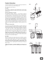
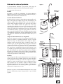
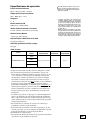
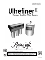
Product Information
Figure 1
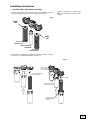
Your RainSoft Ultrefiner II system provides several stages of treatment to
provide you with the best possible drinking water.
The components of the system are:
Pre-Filter
OUTLET
TREATED
WATER TO
FAUCET
The pre-filter is a combination carbon/sediment filter. It removes most
suspended solids 10 microns or larger in size and also reduces incoming
chlorine levels.
Ultrefiner II Membrane Cartridge
Since the water passes through the membrane too slowly to satisfy your
instantaneous demand for water, the system includes a storage tank.
This storage tank contains a rubber bladder and is similar to the tank on
a well system, but smaller. Water passing through the membrane
(“permeate”) is sent to one side of the bladder, while the other side is
pressurized with air (about 8 psi when empty of water). As the tank fills
with water, the air is compressed, providing the pressure needed to
dispense the water when your drinking water faucet is opened. A
hydraulic shutoff valve built into the filter housing assembly automatically turns off flow through the system when the tank is full, and turns
the water back on as the tank is emptied.
DRAIN TO
AIRGAP
WATER
STORAGE TANK
The membrane cartridge consists of a semi-permeable membrane
wound in a spiral to fit a large membrane area into a compact diameter.
This membrane filters on a molecular level and reduces dissolved inorganic solids in the water such as lead, chromium and copper. It will also
reduce cysts, such as cryptosporidium, which have been known to cause
outbreaks of gastrointestinal illness. Since the filtration process is so
fine, the system continuously flushes water across the surface of the
membrane while producing drinking water. The incoming water stream
is split, with some water passing through the membrane as treated water
while the water that flushes the membrane to keep it clean flows to the
drain.
Air Pressured Storage Tank
INLET
UNTREATED
WATER TO
SYSTEM
PR
PO
ST
-F
I
ER
LT
ME
MB
RA
E-
FI
ER
LT
NE
Figure 2
COUNTER
MOUNTED
FAUCET
INLET TO SYSTEM
DRAIN TO AIRGAP
STORAGE TANK
Post-Filter
When the water leaves the storage tank on its way to the faucet, it passes
through a carbon block post-filter. This filter is specially formulated to
reduce volatile organic compounds (i.e. VOC’s); see the performance
data sheet for the specific VOC’s this system is rated to reduce. VOCs
include compounds such as benzene, lindane, and trihalomethanes. The
post-filter also serves as a "polishing filter," the final step in removing any
tastes or odors.
Putting it all together, your RainSoft Ultrefiner II system gives you
multiple lines of defense to protect the drinking water your family relies
on.
5-10 psi AIR CHARGE
POST-FILTER
PERMEATE WATER TO
STORAGE TANK
DRAIN
WATER OUT
MEMBRANE
PRE-FILTER
UNTREATE
D WATER
IN
TREATED
WATER TO
FAUCET
POST-FILTER
MEMBRANE
PRE-FILTER
3
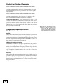
Product Certification Information
Models ULTREFINER II-FMV-BNFP, ULTREFINER II-FMV-BNFV,
ULTREFINER II-FMV-CHFP and ULTREFINER II-FMV-CHFV
conform to NSF/ANSI 58 for the specific performance claims as verified
and substantiated by test data. See performance data sheets for specific
reduction claims.
Models ULTREFINER II-FMV-BNFP, ULTREFINER II-FMV-BNFV,
ULTREFINER II-FMV-CHFP and ULTREFINER II-FMV-CHFV
conform to NSF/ANSI 53 for VOC reduction. See performance data
sheets for individual contaminant and reduction performance.
CALIFORNIA RESIDENTS: Water treatment devices sold to retail
consumers in California, accompanied by certain health claims, must be
certified by the State of California Department of Public Health. The
product accompanied by this manual is not certified in the State of
California for the purpose of making health claims. Please ask your dealer
about California certified models.
Components Requiring Periodic
Replacement
Pre-filter
The pre-filter reduces chlorine and removes most particles and sediment as
small as 10 microns in size from the water supply. The pre-filter requires
periodic replacement every 12 months after installation. Your water quality
and water usage may affect this replacement schedule. Please refer to the
chart on page 14 for replacement part numbers.
Ultrefiner II Membrane Cartridge
The Ultrefiner II membrane cartridge is a spiral wound, semi-permeable
membrane that requires periodic replacement approximately every 24 to 36
months after installation. Your water quality and water usage may affect
this replacement schedule. A water test for TDS reduction is the best indicator of membrane performance. Please refer to the chart on page 14 for
replacement part numbers.
Post-filter
The post-filter will remove unwanted tastes and odors from the water. The
post-filter requires periodic replacement every 12 months after installation
to maintain VOC reduction. Your water quality and water usage may affect
this replacement schedule. Please refer to the chart on page 14 for replacement part numbers.
4
!
Important Note: This Ultrefiner II System
contains replaceable treatment components,
critical for the effective reduction of total
dissolved solids (TDS). The product water
should be tested periodically to verify that the
system is performing properly. See your local
RainSoft Dealer for details.
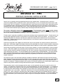
Operational Specifications
Working Pressure
40 psi _ 100 psi (275 kPa _ 689 kPa)
Operating Temperatures
50°F _ 100°F (10°C _ 38°C)
pH Range
2 _ 11
Maximum TDS Level
1400 parts per million (PPM)
!
Maximum Turbidity Influent Level
11 NTU (nephelometric turbidity units)
Important Note:
If the hardness is greater than 5 grains, the
system will still perform properly, but the
longevity of the membrane may be affected.
*
The efficiency and recovery ratings are verified by
testing in accordance with NSF/ANSI Standard 58.
Efficiency rating means the percentage of the
influent water to the system that is available to
the user as reverse osmosis treated water under
operating conditions that approximate typical
daily usage.
Recovery rating means the percentage of the
influent water to the membrane portion of the
system that is available to the user as reverse
osmosis treated water when the system is operated without a storage tank or when the storage
tank is bypassed.
Maximum Hardness Level
5 grains per gallon (85ppm)
Capacity for VOC Reduction
225 gallons (850 liters)
Approximate Flow Rate @ 60psi:
0.94 gpm
Data Chart
Model
Faucet Model
Daily
Production Rates
Efficiency
Rating*
Recovery
Rating*
16.02 gpd / (60.64 L/day)
17.54%
37.23%
BNFP
BNFV
ULTREFINER II -FMV
CHFP
CHFV
Additional Specifications
• The inlet water should be free from iron, manganese, and sulfur.
• This system has been tested for the treatment of water containing
pentavalent arsenic (also known as AS (V), As (+5), or arsenate) at
concentrations of 0.30 mg/L or less. This system reduces pentavalent
arsenic, but may not remove other forms of arsenic. This system is to be
used on water containing a detectable free chlorine residual or on water
supplies that have been demonstrated to contain only pentavalent
arsenic. Treatment with chloramine (combined chlorine) is not sufficient to ensure complete conversion of trivalent arsenic to pentavalent
arsenic. Please see the Arsenic Facts section of the performance data
sheets for further information.
• Do not use this product with water that is microbiologically unsafe or
of unknown quality without adequate disinfection before or after the
system. Systems certified for cyst reduction may be used on disinfected
waters that may contain filterable cysts.
• This system must be installed in accordance with all applicable state
and local laws and regulations.
• This system must be installed in an area not affected by extreme heat,
cold or the elements. The selected installation area must be adequate for
easy service of all parts.
• This system is designed to treat cold water only. The installation must
be on a cold water supply.
5
Items Required for Installation
Tools:
Drill, drill bits, Screwdriver, tube cutter, adjustable wrench, Phillips Offset
Screwdriver, and vinyl gloves .
Parts not included in package:
Inlet shut off valve, PTFE Thread Sealant Tape, 1/4 inch O.D. tubing,
!
Important Notes:
The tubing used for installation must be of
food grade type. John Guest or Parker brand
tubing is recommended for their compatibility
with the fittings on your system.
additional 3/8 inch O.D. tubing and mounting screws.
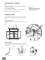
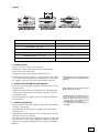
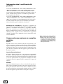
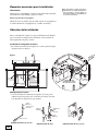
Installation Location
For your convenience, the Ultrefiner II bracket assembly is designed to be
mounted on either side of the cabinet, with the tubing ports pointing to
the back.
Kitchen Sink Installation
• Systems being mounted under a kitchen sink require an air gap faucet. See
figure 3.
Figure 3
H
IT
W
T AP
E
UC R G
FA AI
TO
NS
RU ET
G ABIN
IN
UB OF C
T
L
AL ACK
B
REVERSE OSMOSIS
MOUNTED
UNDER SINK
STORAGE TANK
DRAIN
CONNECTION
FROM AIR GAP
FAUCET
INLET VALVE
CONNECTED TO
COLD WATER LINE
Wall Mount or Other
• Systems being mounted in different location than under a kitchen sink
can use a non air gap faucet with the drain line connecting to a separate
air gap device.
1/2 " DRAIN LINE
GAP-A-FLOW AIR GAP
DRAIN
STACK
"Mr. Drain"
AIR GAP
STAND PIPE
FOR
WASHER,
FLOOR DRAIN
AIR GAP - floor drain
6
AIR GAP - Mr. Drain
AIR GAP - Wall Mount
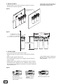
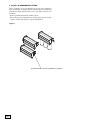
Installation Instructions
1. Install the Filters and Membrane Cartridge
• Wearing sterile gloves, remove the two filters and membrane from the
sterile packaging and place them in the appropriate housings.
Helpful Tip: Be careful not to contaminate the
filters and membrane by touching non-sterile
objects.
Figure 4
WHITE
CAP
BLACK
CAP
POST-FILTER
CARBON BLOCK
REVERSE OSMOSIS
MEMBRANE
PRE-FILTER
CARBON BLOCK
• Secure filter housings by hand tightening Counter Clockwise (looking
from the top) to Ultrefiner II bracket(see figure 5).
Figure 5
HAND TIGHTEN
FILTER HOUSING
ONTO THE BRACKET
PLUG FILTERS INTO THE
BRACKET ASSEMBLY
INSERT FILTER
INSURE FILTER HOUSING
HAS O-RING IN PLACE
ENSURE O-RING IS SEATED
IN FILTER HOUSING
CORRECTLY
7
Helpful Tip: The proper drill bit should be selected
according to the type of material at the desired
installation location.
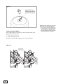
2. Mount the System
Use screws (not supplied) to secure the Ultrefiner II bracket assembly to the
Figure 6
USING PHILIPS OFFSET
SCREWDRIVER
TO SECURE THE ULTREFINER II
E
TH
UM VE
IM ABO
IN
) M IRED
M
.4
U IT
9C
25
(8. REQ I UN
N(
I
IN CE
0I
.
3.5 TAN INER
0
S
1
DI TREF
UL
)
CM
UM
W
IM
IN LO
) M BE
CM ED
.0 UIR OLES
3
(3 EQ H
IN CE R ING
.0
13 TAN UNT
S
DI E MO
TH
Figure 7
15.1 in (38.4 cm)
4.7 in (11.9 cm) without cover
5.0 in (12.7 cm) with cover
7.0 in (17.8 cm) Mimimum required
from mounted wall for cover on / off
10.0 in (25.4 cm)
12.3 in (31.3 cm)
12.5 in (31.8 cm) with Cover
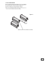
3. Push-IN Tubing Connections:
For all tubing connections on the system, follow these steps to be sure that
the tube is properly installed in the fitting:
•Slightly lubricate the tube with silicone before pushing into the fitting.
•It is important that the tube be fully inserted to the proper depth. You may
measure from the end of the tube & use a marker to put a line as a guide.
•See figure 8 for proper installation practice & depth on each connection.
8
!
Important Note: Ultrefiner II tank port and
outlet port use double o-rings. If you see a leak
from one of these ports, remove the tube and
look into the port to see that both o-rings are
properly aligned, leaving a clear path for the
tubing. If one of the o-rings is moved out of position, it may block tube insertion. Please push it
back into position before inserting the tube.
Figure 8
A
PUSH TUBE STRAIGHT PAST
O-RING TILL TUBE STOPS
TUBE CORRECTLY LOCATED
IN SECURED POSITION
PUSH IN COLLET TO RELEASE TUBE
TUBING CONNECTION PORT
TUBE INSERTION DISTANCE(A)
UF II INLET - 1/4" TUBE
3/4"
UF II DRAIN - 1/4" TUBE
3/4"
UFII TANK - 3/8" TUBE -DOUBLE O-RING
1"
UF II OUTLET - 3/8" TUBE -DOUBLE O-RING
15/16"
STORAGE TANK JG - 3/8" TUBE
3/4"
FAUCET FITTING - 3/8" TUBE
3/4"
4. Install the Faucet
• Select a location for the faucet to be mounted.
• Drill a hole according to the manufacturer’s recommendations.
• Mount the faucet per instructions.
• If using faucet air gap, press drain line tubing onto faucet.
• Use 3/8 inch tubing (not supplied) to connect the faucet to the system
outlet. Make sure the flow restrictor is installed in the 3/8 inch tubing
(not supplied) connected to the outlet of the Ultrefiner II system.
5. Install the Inlet Shut Off Valve (Not Supplied)
• Turn off the cold water supply and open the cold water faucet to relieve
any line pressure;
• Install an inlet shut off valve (not supplied) between the existing shut
off valve and the kitchen faucet, in a way that conforms to state and
local plumbing codes;
• Use 1/4 inch tubing (not supplied) to connect the inlet shut off valve to
the system inlet.
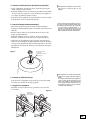
6. Install the Storage Tank
• Select a location for the storage tank. The storage tank can be installed
vertically or horizontally;
• Wrap PTFE Thread Sealant Tape (not supplied) around the threads
of storage tank ;
• Install the shut off valve (supplied) onto the storage tank. The shut off
valve must be in the open position;
• Use the 3/8 inch x 4 foot tubing (supplied) to connect the storage tank
shut off valve to the tank port on the Ultrefiner II Bracket. Additional
tubing may be required pending tank location to location of UltrefinerII Bracket.
Helpful Tip: To secure the connection, wet the end
of the tubing and press the tubing firmly into
cartridge.
!
Important Note: The inlet shut off valve must
have a 1/4 inch tube connection.
Helpful Tip: If the desired installation location is
in the basement, the storage tank can be
mounted in between the floor joists. The closer
the storage tank is to the Ultrefiner II bracket
assembly, the greater the flow of water.
The storage tank can be installed vertically or
horizontally.
9
Figure 9
Wrap PTFE Thread
Sealant Tape Around
3/8-NPT Tank Thread
!
7.Connect the Drain Outlet
Use 1/4 inch tubing (not supplied) to connect the drain outlet to the
appropriate drain connection.
8. Secure the Connections
Attach the red locking clips (supplied) to the connection fittings.
Figure 10
USE RELEASABLE
USE RELEASEABLE
STRAP
TO BAND
STRAPS TO
BAND
TUBING
TOGETHER
TOGETHER TUBING
10
Important Note: The drain connection must
conform to state and local plumbing codes.
If the system is mounted under a kitchen sink,
an air gap faucet will be required. If the
system is mounted in a different location, a
non-air gap faucet may be used, along with a
separate air gap device on the drain line.
9. After SYSTEM START UP
Because the Ultrefiner II bracket assembly and cover are reversible, the
cover is designed with removable side panels for tube routing. Choose
the correct side panel to remove based on the installation.
• Remove the side panel by cutting with knife or clippers.
• Place cover onto Ultrefiner II and ensure tubing is correctly secure to
the one side of the Ultrefiner II bracket assembly.
Figure 11
REMOVE PANEL USING KNIFE OR CLIPPERS
11
System Start Up
1. Turn on the Water Supply
Allow the system to start filling with water.
2. Fast Flush the System
Open the Ultrefiner II faucet and turn the drain barrel to the fast flush
(“F” on the drain barrel)position (see figure 12).
Figure 12
3. Reposition the Drain Barrel
Once the air has been purged from the system, position the drain
barrel in #2 service position(see figure 13). The storage tank will
continue to fill with water.
Figure 13
Helpful Tips: In both the fast flush and # 2 position, the ears of the drain barrel are aligned with
the mounting screws. To make it easier to identify
positions, there is a raised rib at the “F” position.
(See Figure 13)
The drain barrel must always be positioned with the arrow pointing at
numbers 1 – 4 or “F.” In each location, a hole of fixed size is positioned
internally over the drain connection, controlling the flow rate for that
setting. Do not position the drain barrel between settings, as this does
not provide any fine tuning and may even block drain flow by putting an
internal seal directly over the drain connection.
Position “0” shuts off drain flow. The system should never be left in position “0,” as this will cause the membrane to foul. This position is
provided only as a diagnostic tool.
4. Check for Leaks
If a leak is present, make the necessary repairs.
5. Fill the System
When the water stops flowing to the drain, the system should be fully
pressurized and the storage tank should be filled with water.
6. Drain the Storage Tank
Open the Ultrefiner II faucet and drain all the water from the storage
tank.
12
!
Important Note: NSF certified performance data,
as shown on the Performance Data Sheet, is
based on operation at Drain Setting # 2.
Certification results do not apply to other
settings.
!
!
!
Important Note: This procedure will flush any
remaining residue from the storage tank.
Important Note: The 24 hour flush will ensure
the proper rinsing of the Ultrefiner II
Membrane.
Important Note: It is common to experience
cloudy water, cloudy or hazy ice cubes and/or
air bubbles when the system is new or after the
filters/cartridges have been changed. This is
simply due to air trapped in the system which
will soon dissipate.
Helpful Tips: Maintaining a fresh water supply
in the storage tank will promote better operation of the membrane cartridge.
When you go on vacation, close the cold water
inlet valve. When you return from vacation,
open the cold water inlet valve, drain the
storage tank and fast flush the system.
7. Complete the Installation
• If a 24 hour-flush pre-installation is not performed by your local
dealer, it is important to open the faucet and let the system run to drain
for 24 hours first.
• After the 24 hour water flush , close the Ultrefiner II faucet and allow
the storage tank to fill with water. When the storage tank is full, the
system will be ready for operation.
Routine System Maintenance
If the incoming water to your Ultrefiner II system is very poor (for
example: high hardness, high dissolved solids, high iron), you can help
maintain the system's operation by periodically performing this flushing
procedure:
Drain Your Storage Tank
Open the Ultrefiner II faucet and let the water run until the flow turns
into small drips. Close the Ultrefiner II faucet. The Drain flow will
continue to run until your tank has been refilled.
Flush the Membrane And Drain Line
While refilling your storage tank, turn the Drain Dial to the F position.
(See Figure 12 on Page 11.) This will increase the volume of drain water
flushing through the membrane. Once your tank has refilled (typically 2
-3 hours), the Drain flow will shut off. You should then turn the Drain
Dial back to its previous setting.
Periodic System Maintenance and Testing
of Your Water
!
Important Notes: Nitrate reduction units are
acceptable for treatment of influent concentrations of no more than 27 ppm nitrate and 3 ppm
nitrite in combination (measures as “N”) and are
certified for nitrate/nitrite reduction only for
water supplies with a pressure of 40 psi or
greater.
Nitrate Reduction
If you are relying on this system for nitrate reduction, we recommend
testing your water periodically (2 times a year minimum) with a nitrate
test kit (supplied) to ensure that the system is performing properly.
Additional nitrate test kits (part number 12061) can be purchased from
your local RainSoft Dealer.
VOC Reduction
If you are relying on this system for VOC reduction, we recommend
testing your water periodically (2 times a year minimum) to ensure that
the system is performing properly. Your local RainSoft Dealer can
arrange this testing for a nominal fee.
Cyst Reduction
If you are relying on this system for cyst reduction, we recommend
testing your water periodically (2 times a year minimum) to ensure that
the system is performing properly. Your local RainSoft Dealer can
arrange this testing for a nominal fee.
Other Health Reduction Claims
If you are relying on this system for any other health claims, please refer
to the performance data sheets on pages 17 thru 19. See your local
RainSoft Dealer for additional information.
13
How to Change the Filters
1. Turn off the cold water supply to the Ultrefiner II system.
2. Close the storage tank shut-off valve and then open the Ultrefiner II
faucet.
3. Place a drip pan or bucket if necessary to catch the water from the
filter canisters to prevent spillage.
4. To replace the filters, use a Slim Line Spanner Wrench (not supplied)
to unscrew the filter housings from the cap (see figures 14).
!
Important Note: When Unscrewing Filter
Housings use of Slim Line Spanner Wrench is
required. Unscrewing filter housings with use
of other unapproved tools can damage the
filter housings and void warranty.
!
5. Replace the filters and reassemble (see helpful hints).
Important Note: It is recommended that the
sump o-rings be replaced on each filter change
to insure proper compression of the o-ring,
failure to do so may result in over tightening of
the sump to create a seal and can cause undue
stress on the sump and cap that can lead to
cracking of these components under pressure.
6. Once assembled, turn the drain barrel to F position. (see figure 12 on
page 11).
Helpful Tips: To avoid contamination, we
recommend the use of sterile gloves while
changing the system components.
7. Turn on the inlet water to the Ultrefiner II system.
8. Open the storage tank valve and Ultrefiner II faucet. Allow the water
system to flush for 15 minutes.
When changing the membrane cartridge,
verify that the rubber brine seal and O-rings
are secure and in place. Always lubricate the orings with a NON-PETROLEUM based lubricant
to ensure the longevity of the o-rings. Never
over-tighten the housing to the cap _ HAND
9. Turn the Drain Barrel back to predetermined number setting and turn
off the faucet and allow a minimum of 2 hours for the tank to fill up.
If you have replaced the membrane, please open the faucet after 2
hours to drain the first tank of water. This will properly flush the
membrane.
TIGHT ONLY!
Figure 14
RainSoft Filter and Membrane
Replacements
!
The following RainSoft replacement parts are available through your
local RainSoft Dealer:
If you are unable to order replacement parts from your local RainSoft
Dealer, please contact RainSoft at 1-800-860-7638 for assistance.
14
Model
Pre-filter
Membrane
Cartridge
Post-filter
ULTREFINER II-FMV
51635
51637
51636
Important Note: It is important to maintain
the quality of your system by using only
genuine RainSoft replacement filters and
cartridges. Other “made-to-fit” alternative
filters and cartridges claim to perform the
same duties as the original RainSoft parts, but
these items are not approved for use in your
system! “Made-to-fit” alternative filters and
cartridges will increase the probability of
leaks, putting your entire system at risk! Also,
many aftermarket replacement filters are not
tested for safe contact with drinking water.
When “made-to-fit” alternative filters and
cartridges are placed into your RainSoft
Ultrefiner II Premium Drinking Water System,
the product warranty will become null and
void and the system will lose its NSF certification. To guarantee proper operation and certification of your RainSoft Ultrefiner II Premium
Drinking Water System, please use genuine
RainSoft parts.
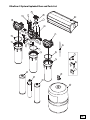
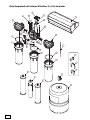
Ultrefiner II System Exploded View and Parts List
13
11
8
7
23
12
2
1
6
4
14
5
3
9
15
16
5
19
10
4
17
20
6
22
21
18
9
9
10
29
10
30
31
26
24
28
27
25
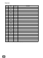
15
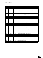
Parts List
Item #
PART #
Quantity
1
51570
1
Description
UF II UNIBODY 1/4 DRAIN & 3/8 TANK ASSEMBLY
2
51571
1
UF II SUMP CAP 1/4 INLET PRE ASSEMBLY
3
51572
1
UF II SUMP CAP 3/8 OUTLET POST ASSEMBLY
4
51561
2
UF II WASHER UNIBODY
5
19914
2
O-RING -013
6
19621
2
3/8 O-RING
7
71497
4
SCREW #10-16 x 1in (15-222)
8
51567
6
SCREW 8-16 X 3/4 SS PAN HEAD
9
12994
3
237 O-RING -9516
10
51605
3
UF II SUMP, SLIM LINE GRAY SPECKLES
11
12632
1
029 O-RING
12
17360
1
UNIBODY DRAIN SHUT OFF CARTRIDGE
13
19899
1
UF II SHUT-OFF CAP
14
19897
1
UF II DRAIN BARREL
15
10102
1
DRAIN VALVE RETAINER
16
51630
1
O-RING 2MM X 16MM EPR 70 D
17
17958
1
015 O-RING
18
19898
1
UF II DRAIN BARREL FACE SEAL
19
71961
1
RESTRICTOR BALL
20
51562
1
O-RING 008
21
51560
1
UF II CHECK BALL PLUG
22*
51631
1
BEADED TIE RELEASEABLE BLACK
23
51741
1
UF II COVER 3 UP ASSEMBLY SILVER
24
17034
1
3/8 TUBE x 1/4” NPT BALL VALVE
25
51640
1
UF II STORAGE TANK ASSEMBLY
26
51635
1
REPLACEMENT UF II PRE CARBON FILTER / BLACK
27
51636
1
REPLACEMENT UF II POST CARBON FILTER VOC / WHITE
28
51637
1
REPLACEMENT UF II 50 GPD MEMBRANE
29 *
30 *
51614
19005
1
3
UF II 1.0 GPM FLOW CONTROL
LOCKING CLIP 3/8in
31 *
19006
2
LOCKING CLIP 1/4in
* You can find item #22, 29, 30 and 31 in the warranty package.
16
1
Hole Dimension
with use of air gap
15
Min Ø 16
"
Max Ø 1"
Air Gap OUT
" Tube
to Drain Connection
3
8
Air Gap IN
Tube to UF II
Drain Connection
1
4"
2
Item #
1
2
17
QTY
Aquion Part
Description
51609
CONTEMP PLUS B-NICKEL FAUCET ASSY
( INCLUDES ITEM # 2)
51624
CONTEMP PLUS CHROME FAUCET ASSY
( INCLUDES ITEM # 2)
51616
CONTEMPORARY FAUCET B-NICKEL ASSY
( INCLUDES ITEM # 2)
51603
CONTEMPORARY FAUCET CHROME ASSY
( INCLUDES ITEM # 2)
51617
FAUCET FITTING 3/8 X 7/16-24 UNS O-RING *
1
1
* This item is included in the faucet assembly, but may be purchased separately.
Product Water
IN with 38" Tube
17
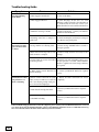
Troubleshooting Guide
Symptom
No Water Running
from Outlet
Extremely low Water
pressure from outlet
or faucet.
Drain Water not shutting off after 2 to 3
hours of running.
Cause
Solution
1. Water Supply Is Turned Off.
1. Turn on the Water.
2. Water Supply Is Blocked
2. Clear Blockage. If this does not work
Blockage could be internal to the Ultrefiner II
or external with the water line. Contact your
Rainsoft Dealer for issues with the Ultrefiner II.
3. Membrane cartridge is Fouled
3. Replace Membrane - Contact your Rainsoft
Dealer for New Membrane.
4. Incoming water line is crimped or
pinched off.
4. Check incoming line and verify no crimps in
line. Remove any pinch points.
1. Storage Tank is not collecting water.
1. Ensure Storage Tank Ball Valve is turned to
the Open position.
2.Water Line from Storage tank or from
Outlet to Faucet is crimped.
2. Remove Crimp from line and verify no line
damage.
3. Storage Tank air pressure has leaked
or has lost pressure.
3. Recharge Air Valve using Bike pump to 8 psi.
If water pressure is restored, contact Rainsoft
Dealer to explain issue. New Storage tank may
be required.
4. Water passage inside Ultrefiner II
Unit has blockage.
4. Contact your Rainsoft Dealer for required
service.
1. Faucet or other connection on system
outlet (such as ice maker) is not shut off
and is not allowing enough back pressure to shut off the diaphragm .
1. Ensure all outlet connections are closed
completely.
2. Drain shutoff cartridge has failed.
2. Contact your Rainsoft Dealer for required
service.
3. Check Ball is leaking.
3. Contact your Rainsoft Dealer for required
service.
If the troubleshooting guide did not resolve the symptom, please contact your local RainSoft Dealer for service. If
you cannot locate your local RainSoft Dealer, please contact RainSoft Customer Service at 1-800-860-7638 or log
onto www.rainsoft.com for the name and location of your nearest Dealer.
18
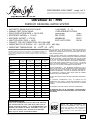
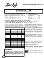
PERFORMANCE DATA SHEET - page 1 of 3
Ultrefiner II - FMV
PREMIUM DRINKING WATER SYSTEM
•
•
•
•
•
•
•
•
•
AUTOMATIC DRAIN SHUT-OFF VALVE
• pH RANGE: 2 - 11
MANUAL FAST FLUSH VALVE
• REPLACEMENT FILTERS:
DAILY PRODUCTION RATE = 16.02 GPD
DESCRIPTION
ITEM#
EFFICIENCY RATING3 = 17.54%
PRE FILTER
51635
RECOVERY RATING4 = 37.23%
MEMBRANE
51637
MAX TDS LEVEL (PPM) = 1400
POST VOC FILTER
51636
CAPACITY FOR VOC REDUCTION: 225 GALLONS
OPERATING PSI OF SUPPLY: 40 - 100 PSI (275 - 689 kPa)
OPERATING TEMPERATURE: 50 - 100oF (10 - 38oC)
This system has been tested according to NSF/ANSI 58 for reduction of the
substances listed below. The concentration of the indicated substances in
water entering the system was reduced to a concentration less than or
equal to the permissible limit for water leaving the system, as specified in
NSF/ANSI 58.
LIST OF contaminant
CONTAMINANT
ARSENIC1
AVERAGE
INFLUENT
CONCENTRATION
(mg/L)
AVERAGE
MAXIMUM
EFFLUENT
AVERAGE PERCENT
EFFLUENT
CONCENTRATION
REDUCTION
CONCENTRATION
(mg/L)
(mg/L)
0.29
0.002
99.3
0.003
9.5
0.14
98.5
0.35
0.031
0.0006
98.1
0.0011
0.3
0.007
97.7
0.013
0.31
0.003
99.0
0.006
3.0
0.038
98.7
0.069
26000
5
>99.99
21
8.6
0.39
95.5
0.51
0.16
0.003
98.1
0.019
32
4.2
87
5.2
25 pCi/L
5 pCi/L
80
5 pCi/L
SELENIUM
0.1
<0.006
>94.0
<0.006
TDS
750
27
96.4
86
11 NTU
0.08 NTU
99.3
0.26 NTU
BARIUM
CADMIUM
CHROMIUM
(HEXAVALENT)
CHROMIUM
(TRIVALENT)
COPPER
CYST
FLUORIDE
LEAD
NITRATE/NITRITE2
RADIUM 226/228
TURBIDITY
THE UNIT SHOULD BE INSTALLED IN AN AREA NOT AFFECTED BY
EXTREME HEAT, COLD, OR THE ELEMENTS. THIS SYSTEM MUST BE
INSTALLED IN ACCORDANCE WITH ALL APPLICABLE STATE AND LOCAL
LAWS AND REGULATIONS.
DO NOT USE WITH WATER THAT IS MICROBIOLOGICALLY UNSAFE OR
OF UNKNOWN QUALITY WITHOUT ADEQUATE DISINFECTION BEFORE
OR AFTER THE SYSTEM. SYSTEMS CERTIFIED FOR CYST REDUCTION
MAY BE USED ON DISINFECTED WATER THAT MAY CONTAIN FILTERABLE CYSTS. THE SYSTEM CONTAINS REPLACEMENT COMPONENTS
CRITICAL FOR EFFECTIVE REDUCTION OF contaminant. THE WATER
SHOULD BE TESTED PERIODICALLY (2 TIMES A YEAR MINIMUM) TO
VERIFY THAT THE SYSTEM IS PERFORMING SATISFACTORILY.
REPLACE ULTREFINER II - FMV MEMBRANE CARTRIDGE 24 TO 36
MONTHS AFTER INSTALLATION, DEPENDING ON WATER CONDITIONS.
A WATER TEST FOR TDS REDUCTION IS THE BEST INDICATOR OF
MEMBRANE PERFORMANCE. REPLACE THE PREFILTER AND POST FILTER CARTRIDGES 12 MONTHS AFTER INSTALLATION OR SOONER
DEPENDING ON WATER CONDITIONS.
THE INLET FEED WATER SHOULD BE FREE FROM IRON, MANGANESE,
SULFUR.
NSF CERTIFIED PERFORMANCE DATA, AS SHOWN ON THE
PERFORMANCE DATA SHEET, IS BASED ON OPERATION AT DRAIN
SETTING # 2. CERTIFICATION RESULTS DO NOT APPLY TO OTHER
SETTINGS.
SEE WARRANTY CARD FOR SPECIFIC WARRANTY INFORMATION
NOT APPROVED FOR USE IN CALIFORNIA. PLEASE REQUEST
CALIFORNIA-SPECIFIC LITERATURE FROM YOUR LOCAL RAINSOFT DEALER.
NSF/ANSI STANDARD 58 TEST CONDITION: 50 ± 3 psi, pH 7.5 ± 0.5, 77 ± 2 ºF
IMPORTANT NOTICE:
READ THIS PERFORMANCE DATA SHEET AND COMPARE
THE CAPABILITIES OF THIS UNIT WITH YOUR ACTUAL
WATER TREATMENT NEEDS. IT IS RECOMMENDED THAT
BEFORE PURCHASING A WATER TREATMENT UNIT, YOU
HAVE YOUR WATER SUPPLY TESTED TO DETERMINE
YOUR ACTUAL WATER TREATMENT NEEDS.
Model ULTREFINER II - FMV - BNFP, ULTREFINER II - FMV - BNFV, ULTREFINER II - FMV
- CHFP and ULTREFINER II - FMV - CHFV are
tested and certified by NSF International
against NSF/ANSI 58 for the reduction of
claims specified on the performance data
sheet.
19
PERFORMANCE DATA SHEET - page 2 of 3
Ultrefiner II - FMV
PREMIUM DRINKING WATER SYSTEM
VOC, Standard 53 Reduction Claims 5
CONTAMINANT
INFLUENT CHALLENGE MAXIMUM PERMISSIBLE
CONCENTRATION
PRODUCT WATER
mg/L
CONCENTRATION mg/L
USEPA
MCL (MG/L)
ALACHLOR
0.050
0.001
0.002
ATRAZINE
0.100
0.003
0.003
BENZENE
0.081
0.001
0.005
CARBOFURAN
0.190
0.001
0.04
CARBON TETRACHLORIDE
0.078
0.0018
0.005
CHLOROBENZENE
0.077
0.001
0.1
CHLOROPICRIN
0.015
0.0002
--------
2,4-D
0.110
0.0017
0.07
DIBROMOCHLOROPROPANE (DBCP)
0.052
0.00002
0.0002
O-DICHLOROBENZENE
0.080
0.001
0.60
P-DICHLOROBENZENE
0.040
0.001
0.075
1,2-DICHLOROETHANE
0.088
0.0048
0.005
1,1-DICHLOROETHYLENE
0.083
0.001
0.007
CIS- 1,2-DICHLOROETHYLENE
0.170
0.0005
0.07
TRANS- 1,2-DICHLOROETHYLENE
0.086
0.001
0.10
1,2-DICHLOROPROPANE
0.080
0.001
0.005
CIS-1,3-DICHLOROPROPYLENE
0.079
0.001
--------
DINOSEB
0.170
0.0002
0.007
ENDRIN
0.053
0.00059
0.002
ETHYLBENZENE
0.088
0.001
0.70
ETHYLENE DIBROMIDE (EDB)
0.044
0.00002
0.00005
BROMOCHLOROACETONITRILE
0.022
0.0005
----------
DIBROMOACETONITRILE
0.024
0.0006
----------
DICHLOROACETONITRILE
0.0096
0.0002
----------
TRICHLOROACETONITRILE
0.015
0.0003
----------
1,1-DICHLORO-2-PROPANONE
0.0072
0.0001
--------
1,1,1-TRICHLORO-2-PROPANE
0.0082
0.0003
--------
HEPTACHLOR
0.025
0.00001
0.0004
HEPTACHLOR EPOXIDE
0.011
0.0002
0.0002
HEXACHLOROBUTADIENE
0.044
0.001
--------
HEXACHLOROCYCLOPENTADIENE
0.060
0.000002
0.05
LINDANE
0.055
0.00001
0.0002
METHOXYCHLOR
0.050
0.0001
0.04
PENTACHLOROPHENOL
0.096
0.001
0.001
SIMAZINE
0.120
0.004
0.004
STYRENE
0.150
0.0005
0.10
1,1,2,2-TETRACHLOROETHANE
0.081
0.001
--------
TETRACHLOROETHYLENE
0.081
0.001
0.005
TOLUENE
0.078
0.001
1.00
TRIBROMOACETIC ACID
0.042
0.001
--------
2,4,5-TP (SILVEX)
0.270
0.0016
0.05
1,2,4-TRICHLOROBENZENE
0.160
0.0005
0.07
1,1,1-TRICHLOROETHANE
0.084
0.0046
0.20
1,1,2-TRICHLORETHANE
0.150
0.0005
0.005
HALOACENTONITRILES (HAN):
HALOKETONES (HK):
TRICHLOROETHYLENE
0.180
0.001
0.005
TRIHALOMETHANES
0.300
0.015
0.08
XYLENES (TOTAL)
0.070
0.001
10
1. THESE SYSTEMS HAVE BEEN TESTED FOR THE TREATMENT OF WATER
CONTAINING PENTAVALENT ARSENIC (ALSO KNOWN AS As(V), As(+5),
OR ARSENATE) AT CONCENTRATIONS OF 0.30 mg/L OR LESS. THIS SYSTEM REDUCED PENTAVALENT ARSENIC, BUT MAY NOT REMOVE OTHER
FORMS OF ARSENIC. THIS SYSTEM IS TO BE USED ON WATER SUPPLIES
CONTAINING A DETECTABLE FREE CHLORINE RESIDUAL AT THE SYSTEM
INLET OR ON WATER SUPPLIES THAT HAVE BEEN DEMONSTRATED TO
CONTAIN ONLY PENTAVALENT ARSENIC. TREATMENT WITH CHLORAMINE
(COMBINED CHLORINE) IS NOT SUFFICIENT TO ENSURE COMPLETE CONVERSION OF TRIVALENT ARSENIC TO PENTAVALENT ARSENIC. PLEASE
SEE THE ARSENIC FACT SECTION OF THE PERFORMANCE DATA SHEET
FOR FURTHER INFORMATION.
2. THE ULTREFINER II IS ACCEPTABLE FOR TREATMENT OF INFLUENT
CONCENTRATIONS OF NO MORE THAN 27 mg/L NITRATE AND 3 mg/L
NITRITE IN COMBINATION MEASURED AS “N” AND IS CERTIFIED FOR
NITRATE/NITRITE REDUCTION ONLY FOR WATER SUPPLIES WITH A PRESSURE OF 280 kPa (40 psig) OR GREATER. ADDITIONAL TREATMENT OR
INDIVIDUAL DESIGN SHALL BE REQUIRED FOR HIGHER INFLUENT LEVELS. IF YOU ARE RELYING ON THE ULTREFINER II FOR NITRATE REDUCTION, WE RECOMMEND TESTING YOUR WATER PERIODICALLY (2 TIMES A
YEAR MINIMUM) WITH A NITRATE TEST KIT (SUPPLIED) TO ENSURE THAT
THE SYSTEM IS PERFORMING PROPERLY. ADDITIONAL NITRATE TEST
KITS (PART NUMBER 12061) CAN BE PURCHASED FROM YOUR LOCAL
RAINSOFT DEALER.
3. EFFICIENCY RATING MEANS THE PERCENTAGE OF INFLUENT WATER TO
THE SYSTEM THAT IS AVAILABLE TO THE USER AS REVERSE OSMOSIS
TREATED WATER UNDER OPERATING CONDITIONS THAT APPROXIMATE
TYPICAL DAILY USAGE.
4. RECOVERY RATING MEANS THE PERCENTAGE OF THE INFLUENT WATER
TO THE MEMBRANE PORTION OF THE SYSTEM THAT IS AVAILABLE TO
THE USER AS REVERSE OSMOSIS TREATED WATER WHEN THE SYSTEM IS
OPERATED WITHOUT A STORAGE TANK OR WHEN THE STORAGE TANK IS
BYPASSED.
5. REDUCTIONS SHOWN ARE FOR VOLATILE ORGANIC CHEMICALS/COMPOUNDS (VOC) AS PER NSF TABLES. CHLOROFORM WAS USED AS A
SURROGATE FOR VOC CLAIMS REDUCTION. THE ACTUAL REDUCTION
RATE OF CHLOROFORM WAS 99.7% AS TESTED BY NSF INTERNATIONAL
AT 200% CAPACITY (I.E 450 GALLONS) PER NSF/ANSI 53 STANDARD.
NSF/ANSI STANDARD 53 TEST CONDITION: 60 ± 3 psi, pH 7.5 ± 0.5, 68 ± 5 ºF
For purchases made in the State of Iowa: This form must be signed and dated by the buyer and seller prior
to the consummation of this sale. The seller for a minimum of two years should retain this form on file.
20
Buyer _________________________________
Name _________________________________
Address _______________________________
City _________ State ___ Zip _____________
Signature ___________ Date ____________
Seller ___________________________________
Name ___________________________________
Address _________________________________
City _______ State ____ Zip _______________
Signature _________
Date ______________
20
PERFORMANCE DATA SHEET - page 3 of 3
Ultrefiner II - FMV
PREMIUM DRINKING WATER SYSTEM
ARSENIC FACTS
Arsenic (As) is a naturally occurring contaminant found in many ground waters. It generally occurs in two forms
(valences or oxidation states): pentavalent arsenic (also know as As(V), As(+5), or arsenate) and trivalent arsenic (also
know as As(III), As(+3), or arsenite). In natural ground water, arsenic may exist as trivalent arsenic, pentavalent arsenic
or a combination of both. Although both forms of arsenic are potentially harmful to human health, trivalent arsenic is
considered more harmful than pentavalent arsenic. More information about arsenic and its toxicity can be found on the
U.S. Environmental Protection Agency website at http://www.epa.gov/safewater/arsenic.html.
The system is designed to remove only pentavalent arsenic. These treatment systems do not provide a feature
for conversion of trivalent arsenic to pentavalent arsenic. The system may remove some trivalent arsenic, however, it has not been evaluated for its ability to remove trivalent arsenic.
Trivalent arsenic is generally more difficult to remove from drinking water than pentavalent arsenic. Trivalent arsenic can
be converted to pentavalent arsenic in the presence of an effective oxidant such as free chlorine. The arsenic in water
containing detectable free chlorine or that has been treated with another effective oxidant will be in the pentavalent
arsenic form. Treatment with chloramine (combined chlorine) is not sufficient to ensure complete conversion of trivalent
arsenic to pentavalent arsenic.
Consumers using public water supplies can contact their utility to verify whether free chlorine treatment chemicals are
being used. Private water supplies and waters that do not have detectable free chlorine residuals should be analyzed to
determine the form(s) of arsenic present and the potential need for oxidation of trivalent arsenic to pentavalent arsenic.
Arsenic does not generally impart color, taste, or smell to water, therefore, it can only be detected by a chemical analytical test. Public water supplies are required to monitor treated water for total arsenic (trivalent arsenic plus pentavalent
arsenic) and the results are available to the public from the utility. Consumers using private water sources will need to
make arrangements for testing. It is recommended the test be conducted by a certified laboratory. Your local RainSoft
dealer, local health departments or environmental protection agencies can help provide a list of certified laboratories.
Some laboratories may also be able to analyze specifically for (speciate) the two forms of arsenic present in a water
sample if requested.
This treatment system was tested under laboratory conditions as defined in NSF/ANSI 58 Reverse Osmosis Drinking
Water Treatment Systems and was found to reduce 0.29 mg/L in the test water to less than 0.010 mg/L, under standard
testing conditions. Actual performance of the system may vary depending on specific water quality conditions at the
consumer’s installation. Following installation of this system, the consumer should have the treated water tested for total
arsenic to verify arsenic reduction is being achieved and the system is functioning properly.
The pentavalent arsenic removal component of this system must be replaced at the end of its useful life of 24 to 36
months. The replacement component (P/N 51637) can be purchased from your local RainSoft dealer. It is important to
maintain the quality of your system by using only genuine RainSoft replacement filters and cartridges. Other “made-tofit” alternative filters and cartridges claim to perform the same duties as the original RainSoft parts, but these items are
not approved for use in your system. “Made-to-fit” alternatives will increase the probability of leaks, putting your entire
system at risk. When “made-to-fit” alternative filters and cartridges are placed into your RainSoft Ultrefiner II System,
the product warranty will become null and void and the system will lose the NSF certification. To guarantee proper operation and certification of your RainSoft system, please use genuine RainSoft parts obtained from your local RainSoft
dealer.
21
Limited
Lifetime Warranty
For as long as you own the equipment
RainSoft Division of Aquion, Inc. believing its
ULTREFINER II PREMIUM DRINKING WATER SYSTEM to be of exceptional
quality, hereby warrants said equipment to its first purchaser at retail as follows:
THE STORAGE TANK HOUSING, FILTER HOUSING, MEMBRANE HOUSING, CONTEMPORARY FAUCET,
CONTEMPORARY PLUS FAUCET ASSY AND UNIBODY CONTROL ARE WARRANTED AGAINST
DEFECTS IN MANUFACTURE FOR THE LIFETIME OF THE FIRST PURCHASER AT RETAIL.
THE MEMBRANE IS PRO-RATE WARRANTED AGAINST DEFECTS IN MANUFACTURE FOR 18 MONTHS
(CREDIT 1/18 TH OF REPLACEMENT COST FOR EACH UNUSED MONTH).
THE ELECTRICAL COMPONENTS (IF APPLICABLE) ARE WARRANTED AGAINST DEFECTS IN MANUFACTURE FOR 12 MONTHS.
THE PRE- AND POST-FILTER SERVICE LIFE IS DEPENDENT ON SPECIFIC WATER CONDITIONS AND
USAGE. REFER TO THE OWNER’S MANUAL FOR RECOMMENDED REPLACEMENT FREQUENCY.
This warranty begins at the time the equipment is first connected for use, and is contingent upon the return of a signed owner's
registration card.
This warranty does not require replacement of the entire unit. If the equipment does not perform properly, you should request
service from the dealer that sold you the equipment. If you are not satisfied, you should notify our Customer Service Manager. If we
are not able to arrange local servicing, you should send the defective part(s) (or, if you prefer, send the entire unit,) directly to the
manufacturer, freight prepaid, with proof of purchase and a copy of this warranty. The defective part(s) (or entire unit) will either
be repaired or new RainSoft part(s) furnished, for a nominal charge to cover labor, handling, packing and the increase, if any, in the
retail price of the part(s) since the date of purchase. Genuine RainSoft parts must be used. Failure to use genuine RainSoft parts will
void the warranty and certifications.
This warranty does not include labor charges, and does not cover installation, transportation, or any other claims or torts. Some
states do not allow the exclusion or limitation of incidental or consequential damages, so parts of the above limitation or exclusion
may not apply to you.
This warranty gives you specific legal rights, and you may also have other rights which vary from state to state. You also have implied
warranty rights. In the event of a problem with warranty service or performance, you may be able to go to a small claims court, a
State court, or a Federal District Court.
This warranty is void if equipment is not installed and operated according to instructions. It does not apply to damage caused by
abuse, accident, neglect, freezing, fire, or other abnormal conditions beyond the company’s control. This warranty is void on any
part from which the manufacturing date has been removed or made illegible.
Benefits will be provided by various types of RainSoft equipment when installed and operated according to the manufacturer's
recommendations. Operational, maintenance and replacement requirements are essential for the product to perform as advertised.
All claims are based on the best available information at the time of printing. Manufacturer makes no representations as to the suitability of this equipment for a particular application. Buyer relies entirely on the dealer's recommendations in the purchase of this
equipment.
Independent RainSoft dealers may include, together with your RainSoft product, a product or component that is not manufactured
by RainSoft or their parent company, Aquion, Inc. Any non-RainSoft product may be covered by the manufacturer of that product,
and is not covered by the RainSoft warranty. Aquion, Inc. does not warrant that your RainSoft product and the non-RainSoft
product will perform properly when used together, and assume no liability therefore.
RainSoft Division of Aquion, Inc.
2080 East Lunt Avenue
Elk Grove Village, Illinois 60007 USA
22
Installer Specification Sheet
Dealer Name:
Phone Number:
Installation Number:
Installation Date:
Model Number:
Serial Number: (See Label)
Line Pressure:
(psi)
Hardness:
Chlorine:
pH:
Inlet TDS:
23
™
RainSoft Division of Aquion, Inc.
2080 East Lunt Avenue
Elk Grove Village, Illinois 60007
Main Switchboard: 1.847.437.9400
Customer Service: 1.800.860.7638
www.rainsoft.com
©2013 RAINSOFT DIVISION OF AQUION, INC.
Rainsoft Division of Aquion, Inc
2080 East Lunt Avenue
ELK Grove Village, Illinois, 60007
1.847.437.9400 or 1800.860.7638
www.rainsoft.com
Sistema de Agua Potable Premium
Tomando la preocupación fuera del agua
Desde 1953
Este producto es fabricado en una instalación certificada por ISO 9001: 2008.
™
Los modelos Ultrefiner II - FMV - BNFP, Ultrefiner II - FMV - BNFV, Ultrefiner II - FMV - CHFP y
Ultrefiner II - FMV - CHFV están probados y certificados por NSF International contra NSF/ANSI
estandár 58 para las afirmaciones de reducción especificadas en la hoja de datos de rendimiento. Consultar
la hoja de datos de rendimiento para las afirmaciones específicas de reducción.
No aprobado para uso en California. Por favor, solicitar manuales de usuario de productos específicos de
California al proveedor RainSoft local.
25
Felicitaciones por su compra de uno de los mejores Sistemas de Agua Potable disponibles para los consumidores.
Este Manual del Usuario está diseñado para ayudarlo en el funcionamiento, manutención y instalación del sistema
Ultrefiner II. Es nuestro sincero deseo que este manual sea claro, conciso y útil para usted como nuevo usuario.
¿ Preguntas? Si usted tiene alguna pregunta referente a la instalación, funcionamiento o servicio de este sistema, por
favor, póngase en contacto con su distribuidor local RainSoft. Su distribuidor local RainSoft está familiarizado con sus
condiciones de agua particulares y será capaz de abordar sus inquietudes con prontitud y eficiencia.
Tabla de Contenidos
Información sobre el producto
27
Información sobre la certificación del producto .................................... 28
Componentes que requieren un reemplazo periódico .......................... 28
Especificaciones de operación .................................................................. 29
Elementos necesarios para la instalación ................................................ 30
Ubicación de la instalación ........................................................................ 30
Instrucciones de instalación ................................................................ 31-34
Arranque del sistema .................................................................................. 35
Mantenimiento rutinario del sistema ...................................................... 36
Mantenimiento periódico del sistema ...................................................... 36
Cómo cambiar los filtros ............................................................................ 37
Números de las piezas de repuesto Rainsoft............................................ 37
Vista despiezada y lista de piezas ........................................................ 38-39
Guía de resolución de problemas ............................................................ ..41
Hoja de datos de rendimiento.............................................................. 42-44
Información sobre la garantía.................................................................... 45
Hoja técnica del instalador ........................................................................ 46
26
Información sobre el producto
Figura 1
Su sistema Rainsoft Ultrefiner II proporciona varias etapas de
tratamiento para proporcionarle la mejor agua potable posible.
Los componentes del sistema son:
ENTRADA DE AGUA
NO TRATADA
Prefiltro
PARA SISTEMA
SALIDA DE AGUA
El prefiltro es un filtro de combinación de carbono/sedimentos.
Elimina la mayoría de los sólidos suspendidos, 10 micras o mayores, y
también reduce los niveles de entrada de cloro.
TRATADA
PARA GRIFO
DRENA JE PARA
BOQUETE DE AIRE
Cartucho filtrante Ultrafiner II
El cartucho filtrante consiste en una membrana semipermeable arrollada en una espiral para adaptar una gran área de membrana a un
diámetro compacto. Esta membrana filtra a un nivel molecular y
reduce sólidos inorgánicos disueltos en el agua tales como plomo,
cromo y cobre. También reducirá los quistes, tales como cryptosporidium, los cuales han sido conocidos por causar brotes de enfermedades gastrointestinales. Cómo el proceso de filtración es tan
eficiente, el sistema envía continuamente agua a través de la superficie
de la membrana, mientras que produce agua potable. La corriente de
agua de entrada es dividida: una cierta cantidad de agua pasa a través
de la membrana convirtiéndose en agua tratada mientras que el agua
.que enjagua la membrana para mantenerla limpia fluye por el
desagüe.
TANQUE DE
ALMACENAMIENTO
DE AGUA
PR
PO
IL
TR
O
AN
LT
RO
A
GRIFO
MONTADO
EN ENCIMERA
ENTRADA PARA
SISTEMA
DRENAJE PARA
BOQUETE DE AIRE
TANQUE DE
ALMACENAMIENTO
Postfiltro
Cuando el agua sale del tanque de almacenamiento en su camino para
el grifo, pasa a través de un postfiltro de bloque de carbono. Este filtro
está especialmente diseñado para reducir los compuestos orgánicos
volátiles (i.e. COV); consulte la hoja de datos de rendimiento para los
COV específicos que este sistema se destina a reducir. Los COV
incluyen compuestos como el benceno, el lindano, y trihalometanos.
El postfiltro también sirve como un "filtro polidor", el paso final en la
eliminación de cualquier gusto u olores.
-F
BR
FI
Figura 2
Tanque de almacenamiento de aire comprimido
Puesto que el agua pasa a través de la membrana demasiado lentamente para satisfacer su demanda instantánea de agua, el sistema
incluye un tanque de almacenamiento. Este tanque de almacenamiento contiene una vejiga de goma y es similar al tanque de un
sistema de pozo, pero más pequeño. El agua que pasa a través de la
membrana ("permeada") es enviada a un lado de la vejiga, mientras
que el otro lado se encuentra presurizado con aire (aproximadamente
8 psi cuando vacío). A medida que el tanque se llena con agua, el aire
se comprime, proporcionando la presión necesaria para dispensar el
agua cuando su grifo está abierto. Una válvula de cierre hidráulico
integrada en el conjunto de la carcasa de los filtros detiene automáticamente el flujo a través del sistema cuando el tanque está lleno y abre
de nuevo el agua cuando se vacía el tanque.
ST
M
ME
E-
5-10 psi AIR CHARGE
POST-FILTRO MEMBRANA
AGUA PERMEADA PARA
TANQUE DE ALMACENAMIENTO
DRENAJE
DEL AGUA
PRE-FILTRO
ENTRADA DE
AGUA NO
TRATADA
AGUA
TRATADA
PARA GRIFO
Poniendo todo junto, su sistema Rainsoft Ultrefiner II le ofrece varias
líneas de defensa para proteger el agua potable de que su familia
depende.
POST-FILTRO
MEMBRANA
PRE-FILTRO
27
Información sobre la certificación del
producto
Los modelos ULTREFINER II - FMV - BNFP, ULTREFINER II - FMV
- BNFV, ULTREFINER II - FMV - CHFP y ULTREFINER II - FMV CHFV están conformes a la norma NSF / ANSI 58 para las afirmaciones específicas de rendimiento verificadas y sustentadas en datos de
prueba. Consultar las hojas de datos de rendimiento para las afirmaciones específicas de reducción.
Los modelos ULTREFINER II - FMV - BNFP, ULTREFINER II - FMV
- BNFV, ULTREFINER II - FMV - CHFP Y ULTREFINER II - FMV CHFV están conformes a la norma NSF/ANSI 53 para la reducción de
los COV. Consultar las hojas de datos de rendimiento para contaminantes individuales y para el rendimiento de reducción.
RESIDENTES DE CALIFORNIA:Los dispositivos de tratamiento de
agua vendidos a los consumidores al por menor en California, acompañados de determinadas declaraciones de propiedades saludables,
deben estar certificados por el Departamento de Salud Pública del
Estado de California. Este producto no está certificado en el Estado de
California para el propósito de hacer declaraciones de propiedades
saludables. Consultar con su distribuidor acerca de los modelos certificados en California.
Componentes que requieren un reemplazo
periódico
Prefiltro
El prefiltro reduce el cloro y elimina la mayoría de las partículas y sedimentos tan pequeños como 10 micras del suministro de agua. El prefiltro
requiere el reemplazo periódico cada 12 meses después de la instalación.
La calidad de su agua y el su uso pueden afectar este programa de reemplazo. Por favor, consultar la tabla de la página 13 para los números de
las piezas de repuesto.
Cartucho filtrante Ultrefiner II
El cartucho filtrante Ultrefiner II es una membrana semipermeable
arrollada en espiral que requiere el reemplazo periódico aproximadamente cada 24 a 36 meses después de la instalación. La calidad de su agua
y el su uso pueden afectar este programa de reemplazo. Por favor,
consultar la tabla de la página 13 para los números de las piezas de
repuesto.
Postfiltro
El postfiltro eliminará los gustos y olores no deseados del agua. El postfiltro requiere el reemplazo periódico cada 12 meses después de la instalación, para mantener la reducción de los COV. La calidad de su agua y
el su uso pueden afectar este programa de reemplazo. Por favor, consultar
la tabla de la página 13 para los números de las piezas de repuesto.
28
!
Nota importante: Este sistema Ultrefiner II
contiene componentes de tratamiento reemplazables, críticos para la reducción efectiva
del total de sólidos disueltos (TSD). El agua
producida debe ser probada periódicamente
para verificar que el sistema funciona correctamente. Consultar con su distribuidor local
Rainsoft para más detalles.
Especificaciones de operación
Presión de funcionamiento
40 psi – 100 psi (275 kPa – 689 kPa)
!
Nota Importante: Si la dureza es mayor que 5
granos, el sistema seguirá funcionando correctamente, pero la longevidad de la membrana
puede verse afectada.
*
Los índices de eficiencia y de recuperación son
verificadas mediante pruebas en conformidad
con la norma NSF / ANSI 58. El índice de eficiencia
se refiere al porcentaje de agua de entrada al
sistema que está disponible para el usuario como
agua tratada por ósmosis inversa, bajo condiciones de funcionamiento que se aproximan del
uso diario típico.
El índice de recuperación significa el porcentaje
del agua afluente a la porción de membrana del
sistema que está disponible para el usuario como
agua tratada por ósmosis inversa, cuando el
sistema opera sin un tanque de almacenamiento
o cuando se salta el tanque de almacenamiento.
Temperaturas de funcionamiento
50°F _ 100°F (10°C _ 38°C)
Rango pH
2 _ 11
Nivel máximo de TSD
1400 partes por millón (PPM)
Nivel máximo de turbidez a la entrada
11 UNT (unidades nefelométricas de turbidez)
Nivel de Dureza Máxima
5 granos por galón (85ppm)
Capacidad para la Reducción de los COV
225 galones (850 litros)
Velocidad aproximada de flujo @ 60psi:
0.94 gpm
Tabla de datos
Modelo
MODELO DEL
GRIFO
ÍNDICE DE
PRODUCCIÓN
ÍNDICE DE
ÍNDICE DE
EFICIENCIA* RECUPERACIÓ
BNFP
BNFV
ULTREFINER II -FMV
16.02 gpd / (60.64 L/dia)
17.54%
37.23%
CHFP
CHFV
Especificaciones adicionales
• El agua de entrada debe estar libre de hierro, manganeso y azufre.
• Este sistema ha sido probado para el tratamiento de agua conte
niendo arsénico pentavalente (también conocido como AS (V), As
(+5) o arseniato) a concentraciones de 0.30 mg/L o menos. Este
sistema reduce el arsénico pentavalente, pero puede no eliminar
otras formas de arsénico. Este sistema debe ser usado en el agua
conteniendo un residuo de cloro libre detectable o en los suministros
de agua que se haya comprobado que sólo contienen arsénico
pentavalente. El tratamiento con cloramina (cloro combinado) no es
suficiente para asegurar la conversión total del arsénico trivalente a
arsénico pentavalente. Por favor, consultar la sección de Datos de
Arsénico en las hojas de datos de rendimiento para obtener más
información.
• No utilizar este producto con agua que no es microbiológicamente
segura o de calidad desconocida sin desinfectarla adecuadamente
antes o después del sistema. Los sistemas certificados para la reduc
ción de quistes pueden ser usados en aguas desinfectadas que pueden
contener quistes filtrables.
• Este sistema debe ser instalado de acuerdo con todas las leyes
y reglamentos estatales y locales aplicables.
• Este sistema debe ser instalado en un área no afectada por el calor
extremo, por el frío o por otros elementos del clima. El área de insta
lación seleccionada debe ser adecuada para facilitar el
funcionamiento de todas las partes.
• Este sistema está diseñado para tratar sólo el agua fría. La instalación
debe hacerse en un suministro de agua fría.
29
Elementos necesarios para la instalación
!
Herramientas:
Taladro, brocas, destornillador, cortador de tubo, llave inglesa ajustable,
destornillador acodado Phillips y guantes de vinilo.
Notas importantes: La tubería usada para la
instalación debe ser de grado alimenticio. Los
tubos John Guest o de marca Parker son
recomendados debido a su compatibilidad con
los accesorios de su sistema.
Partes no proveídas en el paquete :
Válvula de cierre de entrada, cinta de teflón, tubería de 1/4 pulgadas D.
I., tubería adicional de 3/8 pulgadas D. I. y tornillos de montaje.
Ubicación de la instalación
Para su comodidad, el conjunto de soportes Ultrefiner II está diseñado
para ser montado en cualquier lado del armario, con las tomas de la
tubería apuntadas a la parte posterior.
Instalación en el fregadero de cocina
• Los sistemas a montar bajo un fregadero de cocina requieren un grifo
de purga de aire. Ver figura 3.
E
Figura 3
R
DE I
O EA
IF A D
R
G RG
PU
O
ST
UN ET
G R BIN
BIN F CA
U
O
LT
AL ACK
B
OSMOSIS INVERSA
MONTADA BAJO EL
FREGADERO
TANQUE DE
ALMACENAMIENTO
CONEXION DE
DRENAJE DEL GRIFO
DE PURGA DE AIRE
VALVULA DE ENTRADA
CONECTADA A LINEA DE
AQUA FRIA
Montaje en pared y otros
• Si no desea instalar el sistema bajo el fregadero de cocina, puede
utilizar un grifo sin purga de aire con la línea de drenaje conectada
a un dispositivo de purga de aire por separado.
LINEA DE
DRENAJE 1/2 "
BOQUETEDE AIRE
GAP-A-FlOW
CANAL DE
DESAGUE
BOQUETE DE
AIRE
"Mr. Drain"
TUBO
VERTICAL
DESAGUE DEL SUELO
BOQUETE DE AIRE-Desague Del suelo
30
BOQUETE DE AIRE- Mr. Drain
BOQUETE DE AIRE- Montaje de pared
Instrucciones de instalación
1•Instalar los filtros y el cartucho filtrante
Consejo útil: Tener cuidado de no contaminar los
filtros y la membrana al tocar objetos no esterilizados.
•Usando guantes estériles, retirar los dos filtros y la membrana del
envase estéril y colocarlos en las carcasas apropiadas.
Figura 4
TAPA BLANCA
TAPA
NEGRA
POST-FILTRANTE
BLOQUE DE CARBONO
MEMBRANA DE
OSMOSIS INVERSA
BLOQUE DE CARBONO
PREFILTRANTE
•Asegurar las carcasas de los filtros apretando a mano en sentido
contrario a las agujas del reloj (mirando desde la parte superior) al
soporte Ultrefiner II (ver figura 5).
Figura 5
APRETAR A MANO
LA CARCASA DEL
FILTRO AL SUPORTE
ENCHUFAR FILTROS EN EL
CONJUNTO DE SOPORTES
INSERTAR FILTRO
ASEGURAR QUE LA JUNTA
TORICA DE LA CARCASA
DEL FILTRO ESTA EN SU
LUGAR
ASEGURAR QUE LA JUNTA
TORICA ESTA COLOCADA
CORRECTAMENTE EN LA
CARCASA DEL FILTRO
31
2. Montar el sistema
• Utilizar tornillos (no proveidos) para fijar el conjunto de soportes
Ultrefiner II a la ubicación prevista.
Consejo útil: La broca apropiada debe ser
seleccionada de acuerdo con el tipo de material en el lugar de instalación deseado.
Figura 6
L
PU DE
.5
A
E 3 NID
A D LA U
D
I
ER DE
U
A
)
Q
RE CIM
cm
MA R EN
.4
NI
MI ) PO
(25
A
M
I
L
C
C
PU
AN (8.9 II.
ST
.0
DI DAS INER
10
GA TREF
UL
USAR DESTORNILLADOR ACODADO
PHILLIPS PARA ASEGURAR EL
ULTREFINER II
E
AD
RID
UE POR
Q
RE M) DE
MA 3.0 C IOS
NI
MI S (3 IFIC
CIA ADA S OR
N
G
A L
LO
ST
DI .0 PU DE
13 BAJO JE.
DE NTA
O
M
Figura 7
15.1 pulgadas (38.4 cm)
4.7 pulgadas(11.9 cm) sin tapa
5.0 pulgadas(12.7 cm) con tapa
7.0 pulgadas ( 17.8 cm) de distancia
minima requerida de la pared de montaje
10.1 pulgadas (25.4 cm)
12.3 pulgadas(31.3 cm)
12.5 pulgadas(31.8) con tapa
3. Instalar el grifo
• Seleccionar una ubicación para montar el grifo.
• Taladrar un agujero de acuerdo con las recomendaciones del fabri
cante.
• Montar el grifo según las instrucciones.
• Si está usando grifo de purga de aire, empujar el tubo de la línea de
renaje en el grifo.
• Utilizar tubería de 3/8 pulgadas (no proveída) para conectar el grifo a
la salida del sistema. Asegurarse de que el limitador de flujo está insta
lado en el tubo de 3/8 pulgadas (no proveído) conectado a la salida del
sistema Ultrefiner II.
Consejo útil: Para asegurar la conexión, mojar
el extremo del tubo y empujar firmemente el
tubo en el cartucho.
Figura 8
EMPUJAREL TUBO
DIRECTAMENTE ENLA
JUNTA TORICA HASTA QUE EL
TUBO SE DETIENE
32
TUBO CORRECTAMENTE
UBICADO
EN POSICION SEGURA
EMPUJAR PARA LIBERAR EL TUBO
4. Instalar la válvula de cierre de entrada (no proveída)
• Cerrar el suministro de agua fría y abrir el grifo de agua fría para
aliviar cualquier presión de línea;
• Instalar la válvula de cierre de entrada (no proveída) entre la válvula
de cierre existente y el grifo de cocina, de manera que cumpla con
los códigos de plomería estatales y locales;
• Usar tubería de 1/4 pulgadas (no proveída) para conectar la entrada
de la válvula de cierre a la entrada del sistema.
!
Consejo útil: Si el lugar de instalación deseado es
el sótano, el tanque de almacenamiento puede
ser montado entre las vigas de piso. Cuanto más
cerca del tanque de almacenamiento es el
conjunto de soportes Ultrefiner II, mayor será el
flujo de agua. El tanque de almacenamiento
puede ser instalado vertical u horizontalmente.
5. Instalar el tanque de almacenamiento
• Seleccionar una ubicación para el tanque de almacenamiento.
El tanque de almacenamiento puede ser instalado vertical u horizon
talmente;
• Envolver cinta de teflón (no proveída) alrededor de la rosca del
tanque de almacenamiento;
• Instalar la válvula de cierre (proveída) en el tanque de almace
namiento. La válvula de cierre debe estar en la posición abierta;
• Usar el tubo de 3/8 pulgadas x 4 pies (proveído) para conectar la
válvula de cierre del tanque de almacenamiento al orificio del tanque
en el soporte de Ultrefiner II. Tubería adicional puede ser necesaria
dependiendo de la ubicación del tanque y de la ubicación del soporte
Ultrefiner II.
Figura 9
Nota Importante: La válvula de cierre de entrada
debe tener una conexión de tubo de 1/4
pulgadas.
Envolver cinta de teflon
alrededor de
la rosca 3/8-NPT del tanque
de
almacenamiento
6. Conectar la salida de drenaje
Usar tubería de 1/4 pulgadas (no proveída) para conectar la salida
de drenaje a la conexión de drenaje apropiada.
7. Asegurar las conexiones
Enganchar los clips de fijación rojos (proveidos) a los accesorios
de conexión.
Figura 10
!
Nota importante: La conexión de drenaje debe
cumplir con los códigos de plomería estatales y
locales.
Si el sistema está montado bajo un fregadero de
cocina, se requiere un grifo de purga de aire. Si el
sistema está montado en una ubicación diferente, se puede usar un grifo sin purga de aire, con
un dispositivo de purga de aire por separado,
conectado a la línea de drenaje.
USAR CORREA
DESMONTABLE PARA
UNIR LA TUBERIA
33
8. Después del ARRANQUE DEL SISTEMA
Cómo el conjunto de soportes Ultrefiner II y la tapa son reversibles, la
tapa está diseñada con paneles laterales extraíbles para el enrutamiento
de la tubería. Elegir el panel lateral correcto para quitar con base en la
instalación.
• Quitar el panel lateral. Usando cuchillo o tijeras.
• Colocar la tapa sobre el Ultrefiner II y asegurar que la tubería está bien
segura a un lado del conjunto de soportes Ultrefiner II.
Figura 11
QUITAR PANEL USANDO CUCHILLO O TIJERAS
34
Arranque del sistema
1. Abrir el suministro de agua
Dejar que el sistema comience a llenar con agua.
2. Enjaguar rápidamente el sistema
Abrir el grifo Ultrefiner II y girar el cilindro de drenaje para la posición de descarga rápida ("F" en el cilindro de drenaje) (ver figura 12)..
Figura 12
Consejos útiles: Tanto en la posición de descarga
rápida como en la posición #2, las tuercas del
cilindro de drenaje están alineadas con los
tornillos de montaje. Para hacer más fácil la identificación de las posiciones, hay una prominencia
en la posición "F". (Ver Figura 13)
3. Reposicionar el cilindro de drenaje
Una vez que el aire haya sido purgado del sistema, girar el cilindro de
drenaje para la posición de servicio # 2 (ver figura 13). El tanque de
almacenamiento seguirá llenando con agua.
Figura 13
!
El cilindro de drenaje debe siempre colocarse con la flecha apuntando
a los números 1 - 4 o "F". En cada posición, un agujero de tamaño fijo
está colocado internamente sobre la conexión de drenaje, controlando
la velocidad de flujo para esa configuración. No colocar el cilindro de
drenaje entre posiciones, pues que eso no proporciona un ajuste bueno
y puede incluso bloquear el flujo de drenaje, sellando la conexión.
La posición "0" cierra el flujo de drenaje. Nunca se debe dejar el
sistema en la posición "0", ya que esto hará que la membrana falle. Esta
posición está provista sólo como una herramienta de diagnóstico.
4. Revisar si hay fugas
Si hay una fuga, realizar las reparaciones necesarias.
5. Llenar el sistema
Cuando el agua deja de fluir para el desagüe, el sistema debe ser
completamente presurizado y el tanque de almacenamiento debe ser
llenado con agua.
6. Drenar el tanque de almacenamiento
Abrir el grifo Ultrefiner II y drenar toda el agua del tanque de almacenamiento.
Nota importante: Los datos de rendimiento certificados NSF, como se muestra en la hoja de datos
de rendimiento, se basan en el funcionamiento
en la posición de drenaje #2. Los resultados de
certificación no son aplicables a otros contextos.
!
Nota Importante: Este procedimiento hará que se
vacíe cualquier residuo restante del tanque de
almacenamiento.
N
!
Nota importante: La descarga de 24 horas asegurará el enjuague apropiado de la membrana
Ultrefiner II
!
Nota importante: Es común obtener agua turbia,
cubitos de hielo nublados y/o burbujas de aire
cuando el sistema es nuevo o después que los
filtros/cartuchos han sido reemplazados. Esto es
simplemente debido al aire atrapado en el
sistema, que pronto se disipará .
Consejos útiles: El mantenimiento de un suministro de agua dulce en el tanque de almacenamiento
podrá
promover
un
mejor
funcionamiento del cartucho filtrante. Cuando se
va de vacaciones, cerrar la válvula de entrada de
agua fría. Cuando regrese de vacaciones, abrir la
válvula de entrada de agua fría, drenar el tanque
de almacenamiento y enjaguar rápidamente el
sistema.
35
7. Terminar la instalación
• Si una descarga de 24 horas de preinstalación no es llevada a cabo por
su distribuidor local, es importante abrir el grifo y dejar que el sistema
funcione para drenar durante 24 horas.
• Después de la descarga de agua 24 horas, cerrar el grifo Ultrefiner II y
permitir que el tanque de almacenamiento se llene de agua. Cuando el
tanque de almacenamiento esté lleno, el sistema estará listo para uso.
Mantenimiento rutinario del sistema
Si el agua que ingresa a su sistema Ultrefiner II es muy pobre (por
ejemplo: alta dureza, alto contenido de sólidos disueltos, alto contenido
de hierro), usted puede ayudar a mantener el funcionamiento del sistema
realizando periódicamente este procedimiento de drenaje:
Vaciar su tanque de almacenamiento
Abrir el grifo Ultrefiner II y dejar correr el agua hasta que el flujo se
convierta en pequeñas gotas. Cerrar el grifo Ultrefiner II. El flujo de
drenaje continuará corriendo hasta que el tanque sea rellenado.
Enjaguar la membrana y la línea de drenaje
Mientras va a rellenar el tanque de almacenamiento, girar el selector de
drenaje a la posición F (Ver la Figura 12 en la página 11). Esto aumentará el volumen de agua de drenaje corriendo a través de la membrana.
Una vez que el tanque ha rellenado (por lo general 2-3 horas), el flujo de
drenaje se detendrá. A continuación, debe girar el selector de drenaje a
su configuración anterior.
Mantenimiento periódico del sistema y
pruebas de su agua
Reducción de nitrato
Si usted depende de este sistema para la reducción de nitratos, se
recomienda probar el agua periódicamente (2 veces al año como
mínimo) con un kit de pruebas de nitrato (proveído), para asegurar que
el sistema está funcionando correctamente. Otros kits de prueba de
nitrato (número 12061) se pueden comprar a su distribuidor local
Rainsoft.
Reducción de los COV
Si usted depende de este sistema para la reducción de los COV, se
recomienda probar el agua periódicamente (2 veces al año como
mínimo), para asegurar que el sistema está funcionando correctamente.
Su distribuidor local Rainsoft puede organizar esta prueba por una tarifa
nominal.
Reducción de quistes
Si usted depende de este sistema para la reducción de quistes, se
recomienda probar el agua periódicamente (2 veces al año como
mínimo), para asegurar que el sistema está funcionando correctamente.
Su distribuidor local Rainsoft puede organizar esta prueba por una tarifa
nominal.
Otras declaraciones de propiedades saludables
Si usted depende de este sistema para otras declaraciones de propiedades
saludables, por favor consultar las hojas de datos de rendimiento en las
páginas 17 a 19. Consultar su distribuidor Rainsoft para obtener información adicional.
36
!
Notas importantes: las unidades de reducción
de nitratos son aceptables para el tratamiento
de concentraciones de no más que 27 ppm de
nitrato y de 3 ppm de nitrito en combinación
(medidas como "N") y están certificadas para la
reducción de nitrato/nitrito sólo para suministros de agua con una presión de 40 psi o
mayor.
Cómo cambiar los filtros
!
1.Cerrar el suministro de agua fría al sistema Ultrefiner II.
Nota importante: Al desenroscar las carcasas de
los filtros usar la llave de filtros Slim Line.
Desenroscar las carcasas de los filtros usando
otras herramientas no autorizadas puede dañar
las carcasas de los filtros y anular la garantía.
2. Cerrar la válvula de cierre del tanque de almacenamiento y abrir el
grifo Ultrefiner II.
3.Colocar una bandeja de goteo o cubeta si necesario para coger el
agua de los cartuchos de los filtros, para evitar derrames.
4. Para reemplazar los filtros, utilizar una llave de filtros Slim Line (no
proveída) para desenroscar las carcasas de los filtros de la tapa (ver las
figuras 14).
!
5. Reemplazar los filtros y volver a montar (ver consejos útiles).
6. Una vez montado, girar el cilindro de drenaje a la posición F. (ver la
figura 12 en página 11).
Nota importante: “Se recomienda reemplazar las
juntas tóricas del contenedor con motas grises
para asegurar la adecuada compresión de la
junta tórica, no hacerlo puede resultar en apretar
del contenedor para crear un sello y puede causar
una tensión indebida en el contenedor y la tapa
que puede causar la rotura de estos componentes
bajo presión.”
Consejos útiles: Para evitar contaminación, se
recomienda el uso de guantes estériles
mientras cambia los componentes del sistema. Al
cambiar el cartucho filtrante, verificar que el sello
de salmuera y las juntas tóricas están firmes y en
su lugar.
Siempre lubricar las juntas tóricas con un lubricante NO DERIVADO DE PETRÓLEO para garantizar la longevidad de las juntas tóricas. No
apretar demasiado las carcasas a la tapa - AJUSTE
MANUAL SÓLO.
7. Abrir el agua de entrada al sistema Ultrefiner II.
8. Abrir la válvula del tanque de almacenamiento y el grifo Ultrefiner
II. Dejar que el agua corra para enjaguar durante 15 minutos.
9. Girar el cilindro de drenaje a sus posiciones de número predeterminadas, cerrar el grifo y dejar que el tanque se llene por un mínimo de
2 horas. Si ha reemplazado la membrana, por favor, abrir el grifo
después de 2 horas para vaciar el primer tanque de agua. Esto hará que
se enjuague correctamente la membrana.
Figura 14
!
Membrana y filtro Rainsoft de repuesto
Las siguientes piezas de repuesto Rainsoft están disponibles a través de
su distribuidor local Rainsoft.
Si usted no puede pedir piezas de repuesto a su distribuidor local
Rainsoft, por favor póngase en contacto con Rainsoft al 1-800-8607638 para obtener ayuda.
Modelo
Prefiltro
Cartucho
filtrante
Postfiltro
ULTREFINER II-FMV
51635
51637
51636
Nota importante: Para mantener la calidad de su
sistema es importante utilizar sólo filtros de
repuesto y cartuchos genuinos Rainsoft. Otros
filtros y cartuchos alternativos “hechos a
medida” pretenden realizar las mismas funciones
que las piezas originales Rainsoft, pero no están
aprobados para ser usados en su sistema! Filtros
y cartuchos alternativos “hechos a medida”
aumentarán la probabilidad de fugas, poniendo
todo el sistema en riesgo! Además, muchos filtros
de repuesto del mercado de accesorios no han
sido probados para el contacto con agua potable
segura.
Al colocar filtros y cartuchos alternativos “hechos
a medida” en su Sistema de Agua Potable
Premium Rainsoft Ultrefiner II, la garantía del
producto será nula y sin efecto y el sistema
perderá su certificación NSF. Para garantizar el
correcto funcionamiento y certificación de su
Sistema de Agua Potable Premium Rainsoft
Ultrefiner II, por favor, utilizar piezas originales
Rainsoft.
37
Vista despiezada del sistema Ultrefiner II y lista de piezas
13
11
8
7
23
12
2
1
6
4
14
5
3
9
15
16
5
19
10
4
17
20
6
22
21
18
9
9
10
29
10
30
31
26
24
28
27
25
38
Lista de Piezas
Ítem #
Pieza #
Cantidad
1
51570
1
Descripción
CONJUNTO DESAGÜE 1/4 & TANQUE 3/8 UF II
2
51571
1
CONJUNTO DE ENTRADA TAPA DE CONTENEDOR 1/4 UF II
3
51572
1
CONJUNTO SALIDA TAPA DE CONTENEDOR 3/8
4
51561
2
ARANDELA UF II
5
19914
2
JUNTA TÓRICA -013
6
19621
2
JUNTA TÓRICA 3/8
7
71497
4
TORNILLO #10-16 x 1 pulg. (15-222)
8
51567
6
TORNILLO CABEZA PLANA 8-16 x 3/4 SS
9
12994
4
JUNTA TÓRICA 237 -9516
10
51605
3
CONTENEDOR UF II, SLIM LINE MOTAS GRISES
11
12632
1
JUNTA TÓRICA 029
12
17360
1
CARTUCHO DE CIERRE DEL DESAGÜE
13
19899
1
TAPA DE CIERRE UF II
14
19897
1
UF II CILINDRO DE DRENAJE
15
10102
1
RETENEDOR DE VÁLVULA DE DRENAJE
16
51630
1
JUNTA TÓRICA 2MM x 16MM EPR 70 D
17
17958
1
JUNTA TÓRICA 015
18
19898
1
SELLO DE CILINDRO DE DRENAJE UF II
19
71961
1
BOLA DE ESTRANGULACIÓN
20
51562
1
JUNTA TÓRICA 008
21
51560
1
ENCHUFE DE BOLA DE RETENCIÓN UF II
22*
51631
1
ATADURA REBORDEADA LIBERABLE NEGRA
23
51741
1
CONJUNTO DE LA TAPA UF II
24
17034
1
VÁLVULA DE BOLA NPT TUBO 3/8 x 1/4“
25
51640
1
CONJUNTO DEL TANQUE DE ALMACENAMIENTO UF II
26
51635
1
REEMPLAZO PREFILTRO DE CARBÓN UF II / NEGRO
27
51636
1
REEMPLAZO POSTFILTRO DE COV DE CARBÓN UF II / BLANCO
28
51637
1
REEMPLAZO MEMBRANA 50 GPD UF II
29 *
30 *
51614
19005
1
3
CONTROL DE FLUJO 1.0 GPM UF II
CLIP DE FIJACIÓN 3/8 pulg.
31 *
19006
2
CLIP DE FIJACIÓN 1/4 pulg.
*Puede encontrar el ítem nº 22, 29, 30 y 31 en el paquete de garantía.
39
Vista Despiezada del Grifo y Lista de Piezas
1
Dimension del Agujero
con boquete de aire
15
"
Min Ø 16
Max Ø 1"
SALIDA de Boquete
de Aire Tubo de 3/8" para
Conexion de Drenaje
2
Ítem #
Cant.
51624
1
51603
40
Descripción
CONJ.
GRIFO
CONTEMP
PLUS
B-NICKEL
PLUS
CHROME
(incluye ítem # 2)
CONJ.
GRIFO
CONTEMP
(incluye ítem # 2)
1
51616
2
ENTRADA del Boquete
de Aire Tubo de 1/4" para Conexion
de Drenaje UF II
Pieza Aquion
51609
ENTRADA
de Agua Producida
con Tubo de 3/8"
1
51617
CONJ. GRIFO CONTEMPORÁNEO
B-NICKEL (incluye ítem # 2)
CONJ. GRIFO CONTEMPORÁNEO CHROME
(incluye ítem # 2)
ACCESORIO DE GRIFO 3/8 x JUNTA TÓRICA
UNS 7/16-24 *
. Este ítem no se incluye en el conjunto de grifo, pero se puede comprar por separado
Guía de resolución de problemas
Síntoma
No hay agua
corriendo de la salida
Presión del agua
proveniente de la
salida o del grifo
extremadamente baja.
El agua de drenaje no
cierra después de 2 a 3
horas de
funcionamiento
Causa
Solución
1. El suministro de agua está cerrado.
1. Abrir el agua.
2. El suministro de agua está bloqueado.
2. Eliminar la obstrucción. Si esto no funcione,
la obstrucción puede ser interna a el Ultrefiner
II
o externa, en la tubería del agua. Póngase en
contacto con su distribuidor Rainsoft para
cuestiones relativas al Ultrefiner II.
3. El cartucho filtrante está obstruido.
3. Reemplazar la membrana - Póngase en
contacto con su distribuidor Rainsoft para
nueva membrana.
4. La tubería de entrada del agua está
torcida o pellizcada.
4. Verificar que no hay torceduras en la tubería
de entrada. Retirar todos los puntos de pellizco.
1. El tanque de almacenamiento no está
recogiendo agua.
1. Asegurarse que la válvula de bola del tanque
de almacenamiento está en la posición abierta.
2. La tubería del tanque de almacenamiento o del grifo está torcida.
2. Reparar la torcedura de la tubería y verificar
si no hay daños.
3. El aire del tanque de almacenamiento
se ha escapado o ha perdido presión.
3. Recargar la válvula de aire utilizando una
bomba de bicicleta a 8 psi. Si la presión de agua
es restaurada, póngase en contacto con su
distribuidor Rainsoft para explicar los detalles.
Puede ser requerido un tanque de almacenamiento nuevo.
4. La pasaje de agua en el interior de la
unidad Ultrefiner II tiene una obstrucción.
4. Póngase en contacto con su distribuidor
Rainsoft para el servicio requerido.
1. El grifo u otra conexión en la salida
del sistema (por ejemplo, una máquina
de hielo) no está cerrada y no está
permitiendo suficiente presión para
cerrar el diafragma.
1. Asegurarse que todas las conexiones de
salida están completamente cerradas.
2. El cartucho de cierre del desagüe ha 2. Póngase en contacto con su distribuidor
fallado.
Rainsoft para el servicio requerido.
3. La bola de retención está goteando.
3. Póngase en contacto con su distribuidor
Rainsoft para el servicio requerido.
Si la guía de resolución de problemas no resolvió el síntoma, por favor póngase en contacto con su distribuidor local Rainsoft para el
servicio. Si no puede localizar su distribuidor local Rainsoft, por favor póngase en contacto con el Servicio al Cliente Rainsoft al 1800-860-7638 o ingrese a www.rainsoft.com para el nombre y la ubicación de su distribuidor más cercano.
41
HOJA DE DATOS DE RENDIMIENTO - página 1 de 3
Ultrefiner II - FMV
Sistema de Agua Potable Premium
•
•
•
•
•
•
•
•
•
VÁLVULA DE CIERRE DE DRENAJE AUTOMÁTICA
• RANGO pH: 2 – 11
VÁLVULA DE DESCARGA RÁPIDA MANUAL
• FILTROS DE REPUESTO:
ÍNDICE DE PRODUCCIÓN DIARIA = 16.02 GPD
DESCRIPCIÓN
ÍTEM:
3
ÍNDICE DE EFICIENCIA =17.54%
PREFILTRO
51635
ÍNDICE DE RECUPERACIÓN = 37.23%
MEMBRANA
51637
NIVEL MÁX DE TSD (PPM) = 1400
POSTFILTRO DE COV 51636
CAPACIDAD PARA LA REDUCCIÓN DE COV: 225 GALONES
PSI DE FUNCIONAMIENTO DEL SUMINISTRO: 40 – 100 PSI (275 – 689 kPa)
TEMPERATURA DE FUNCIONAMIENTO: 50 – 100º F (10 a 38º C)
Este sistema ha sido probado siguiendo la norma NSF / ANSI 58 para la
reducción de las sustancias citadas a continuación. La concentración de las
sustancias indicadas en el agua entrando en el sistema fue reducida a una
concentración menor o igual al límite permitido para el agua saliendo del
sistema, en conformidad con la norma NSF / ANSI 58.
LA UNIDAD DEBE SER INSTALADA EN UN ÁREA NO AFECTADA POR EL
CALOR, POR EL FRÍO O POR OTROS ELEMENTOS DEL CLIMA. ESTE
SISTEMA DEBE SER INSTALADO DE ACUERDO CON TODAS LAS LEYES
Y REGLAMENTOS LOCALES Y ESTATALES APLICABLES.
Lista de los contaminantes
CONCENTRACIÓN
MEDIA EN EL
AFLUENTE (MG/L)
CONCENTRACIÓN
MEDIA EN EL
EFLUENTE (MG/L
REDUCCIÓN PORCENTUAL MEDIA
CONCENTRACIÓN
MÁXIMA EN EL
EFLUENTE (MG/L)
0.29
0.002
99.3
0.003
9.5
0.14
98.5
0.35
0.031
0.0006
98.1
0.0011
0.3
0.007
97.7
0.013
0.31
0.003
99.0
0.006
COBRE
3.0
0.038
98.7
0.069
QUISTE
26000
5
>99.99
21
8.6
0.39
95.5
0.51
0.16
0.003
98.1
0.019
32
4.2
87
5.2
25 pCi/L
5 pCi/L
80
5 pCi/L
SELENIO
0.1
<0.006
>94.0
<0.006
TSD
750
27
96.4
86
11 NTU
0.08 NTU
99.3
0.26 NTU
CONTAMINANTE
ARSÉNICO1
BARIO
CADMIO
CROMO
(HEXAVALENTE)
CROMO (TRIVALENTE)
FLUORURO
PLOMO
NITRATE/NITRITE2
RADIO 226/228
TURBIDEZ
CONDICIÓN DE PRUEBA NSF/ANSI NORMA 58: 50 ± 3 psi, pH 7.5 ± 0.5, 77 ± 2º F
AVISO IMPORTANTE:
LER ESTA HOJA DE DATOS DE RENDIMIENTO Y COMPARAR LAS CAPACIDADES DE ESTA UNIDAD CON SUS
NECESIDADES REALES DE TRATAMIENTO DE AGUA. SE
RECOMIENDA QUE ANTES DE COMPRAR UNA UNIDAD DE
TRATAMIENTO DE AGUA, QUE PONGA A PRUEBA SU SUMINISTRO DE AGUA PARA DETERMINAR SUS NECESIDADES REALES DE TRATAMIENTO DE AGUA.
42
NO USAR CON AGUA QUE SEA MICROBIOLÓGICAMENTE INSEGURA
O DE CALIDAD DESCONOCIDA SIN DESINFECTARLA ADECUADAMENTE ANTES O DESPUÉS DEL SISTEMA. SISTEMAS CERTIFICADOS
PARA LA REDUCCIÓN DE QUISTES PUEDEN SER USADOS EN AGUA
DESINFECTADA QUE PUEDE CONTENER QUISTES FILTRABLES. EL
SISTEMA CONTIENE PIEZAS DE REPUESTO ESENCIALES PARA LA
REDUCCIÓN EFECTIVA DE LOS CONTAMINANTES. EL AGUA DEBE
SER PROBADO PERIÓDICAMENTE (2 VECES AL AÑO COMO MÍNIMO)
PARA VERIFICAR QUE EL SISTEMA ESTÁ FUNCIONANDO CORRECTAMENTE.
REEMPLAZAR EL CARTUCHO FILTRANTE ULTREFINER II - FMV 24 A
36 MESES DESPUÉS DE LA INSTALACIÓNEN, EN FUNCION DE LAS
CONDICIONES DE AGUA. UNA PRUEBA DE AGUA PARA LA
REDUCCIÓN DE TSD ES EL MEJOR INDICADOR DEL RENDIMIENTO
DE LA MEMBRANA. REEMPLAZAR LOS CARTUCHOS DEL PREFILTRO Y
DEL POSTFILTRO 12 MESES DESPUÉS DE LA INSTALACIÓN O ANTES
DEPENDIENDO DE LAS CONDICIONES DE AGUA.
EL AGUA DE ENTRADA PARA CONSUMO DEBE ESTAR LIBRE DE HIERRO, MANGANESO Y AZUFRE.
LOS DATOS DE RENDIMIENTO CERTIFICADOS NSF, TAL COMO
APARECEN EN LA HOJA DE DATOS DE RENDIMIENTO, SE BASA NEL
FUNCIONAMIENTO EN LA POSICIÓN #2. LOS RESULTADOS DE
CERTIFICACIÓN NO SE APLICAN A OTRAS POSICIONES.
CONSULTAR LA TARJETA DE GARANTÍA PARA OBTENER
INFORMACIÓN ESPECÍFICA DE LA GARANTÍA.
NO APROBADO PARA USO EN CALIFORNIA. POR FAVOR,
SOLICITAR MANUALES DE USUARIO DE PRODUCTOS
ESPECÍFICOS DE CALIFORNIA A SU DISTRIBUIDOR LOCAL
RAINSOFT.
Los modelo ULTREFINER II - FMV - BNFP,
ULTREFINER II - FMV – BNFV, ULTREFINER II FMV - CHFP y ULTREFINER II - FMV - CHFV
están probados y certificados por NSF en
NSF/ANSI 58 para las afirmaciones específicas
de reducción sustentadas en datos de prueba.
HOJA DE DATOS DE RENDIMIENTO - página 2 de 3
Ultrefiner II - SFMV
Sistema de Agua Potable Premium
COV, Declaraciones de reducción – Norma 535
1. Estos sistemas han sido probados para el tratamiento de agua
CONCENTRACIÓN
MEDIA AFLUENTE
MG/L
CONCENTRACIÓN MÁXIMA
ADMISIBLE EN EL AGUA
PRODUCIDA (MG/L)
LCM APE EE. UU.
(MG/L)
ALACLOR
0.050
0.001
0.002
ATRAZINA
0.100
0.003
0.003
menos. Este sistema redujo el arsénico pentavalente, pero puede
BENCENO
0.081
0.001
0.005
no eliminar otras formas de arsénico. Este sistema debe ser uti-
CARBOFURANO
0.190
0.001
0.04
lizado en los suministros de agua que contienen un residuo de
CARBON TETRACLORURO
0.078
0.0018
0.005
cloro libre detectable en la entrada del sistema o en los sumin-
CLOROBENCENO
0.077
0.001
0.1
istros de agua que se ha demostrado que sólo contienen arsénico
CLOROPICRINA
0.015
0.0002
--------
pentavalente. El tratamiento con cloramina (cloro combinado) no
2,4-D
0.110
0.0017
0.07
es suficiente para asegurar la conversión total del arsénico triva-
DIBROMOCLOROPROPANO (DBCP)
0.052
0.00002
0.0002
O-DICLOROBENCENO
0.080
0.001
0.60
P-DICLOROBENCENO
0.040
0.001
0.075
1,2-DICLOROETANO
0.088
0.0048
0.005
1,1-DICLOROETILENO
0.083
0.001
0.007
CIS- 1,2-DICLOROETILENO
0.170
0.0005
0.07
ciones del afluente de no más de 27 mg/L de nitrato y 3 mg/L de
TRANS-1,2-DICLOROETILENO
0.086
0.001
0.10
nitrito en combinación medidos como "N" y está certificado para
1,2-DICLOROPROPANO
0.080
0.001
0.005
la reducción de nitrato/nitrito sólo para los suministros de agua
CIS-1 ,3-DICHLOROPROPYLENE
0.079
0.001
--------
con una presión de 280 kPa (40 psi) o mayor. Para niveles del
DINOSEB
0.170
0.0002
0.007
afluente más altos se requerirá tratamiento adicional o diseño
ENDRINA
0.053
0.00059
0.002
individual. Si usted depende del Ultrefiner II para la reducción de
ETILBENCENO
0.088
0.001
0.70
nitratos, recomendamos probar el agua periódicamente (2 veces
DIBROMURO DE ETILENO (EDB)
0.044
0.00002
0.00005
al año como mínimo) con un kit de prueba de nitrato (proveído)
BROMOCLOROACETONITRILO
0.022
0.0005
----------
de prueba de nitrato (pieza número 12061) pueden ser adquiridos
DIBROMOACETONITRILO
0.024
0.0006
----------
a su distribuidor local Rainsoft.
DICLOROACETONITRILO
0.0096
0.0002
----------
TRICLOROACETONITRILO
0.015
0.0003
----------
1,1-DICLORO-2-PROPANONA
0.0072
0.0001
--------
por ósmosis inversa bajo condiciones de funcionamiento que se
1,1,1-TRICLORO-2-PROPANO
0.0082
0.0003
--------
aproximan del uso diario normal.
HEPTACLORO
0.025
0.00001
0.0004
EPÓXIDO DE HEPTACLORO
0.011
0.0002
0.0002
4. Índice de recuperación se refiere al porcentaje de agua aflu-
HEXACLOROBUTADIENO
0.044
0.001
--------
ente a la porción de membrana del sistema que está disponible
HEXACLOROCICLOPENTADIENO
0.060
0.000002
0.05
LINDANO
0.055
0.00001
0.0002
METOXICLORO
0.050
0.0001
0.04
PENTACLOROFENOL
0.096
0.001
0.001
5. Las reducciones que se muestran son para químicos/com-
SIMAZINA
0.120
0.004
0.004
puestos orgánicos volátiles (COV), como por las tablas de la NSF.
ESTIRENO
0.150
0.0005
0.10
1,1,2,2-TETRACLOROETANO
0.081
0.001
--------
ción de los COV. El índice de reducción real de cloroformo fue de
TETRACLOROETILENO
0.081
0.001
0.005
99.7% según pruebas realizadas por NSF International en 200%
TOLUENO
0.078
0.001
1.00
ACID TRIBROMOACETIC
0.042
0.001
--------
2,4,5-TP (SILVEX)
0.270
0.0016
0.05
1,2,4-TRICLOROBENCENO
0.160
0.0005
0.07
1,1,1-TRICLOROETANO
0.084
0.0046
0.20
1,1,2-TRICLOROETANO
0.150
0.0005
0.005
CONTAMINANTE
conteniendo arsénico pentavalente (también conocido como
As(V), As(+5), o arseniato) a concentraciones de 0.30 mg/L o
lente a arsénico pentavalente. Por favor, consultar la sección
arsénico en la hoja de datos de rendimiento para obtener más
información.
2. El Ultrefiner II es aceptable para el tratamiento de concentra-
para asegurar que el sistema funciona correctamente. Otros kits
HALOACENTONITRILES (HAN):
HALOCETONAS (HK):
3. Índice de eficiencia se refiere al porcentaje de agua de entrada
al sistema que está disponible para el usuario como agua tratada
TRICLOROETILENO
0.180
0.001
0.005
TRIHALOMETANOS
0.300
0.015
0.08
XILENOS (TOTAL)
0.070
0.001
10
para el usuario como agua tratada por ósmosis inversa cuando el
sistema funciona sin un tanque de almacenamiento o cuando se
salta el tanque de almacenamiento.
Se usó cloroformo como sustituto para las declaraciones de reduc-
de su capacidad (i. e. 450 galones), en conformidad con la norma
NSF / ANSI 53.
CONDICIÓN DE PRUEBA NSF/ANSI NORMA 53: 60 ± 3 psi, pH 7.5 ± 0.5, 68 ± 5 ºF
Para las co mpras realizadas en el Estad o de Iowa: este formu lario d eb e s er firmado y fechado por el co mprador y el vendedo r antes d e la co nsu mación d e
la venta. Durante un p erío do mínimo de dos año s el vend ed or deberá cons ervar este formulario en el archivo.
Comp rado r_ _____ ____ ______ ____ ____ _____ ____ _____ _____ ____ Vendedo r_ _____ ____ _____ _____ ____ _____ _____ ___ ______ ____ _____ __
Nombre_ ____ _____ ____ _____ _____ ____ ____ _____ _____ ____ ____ No mbre_ ____ _____ ____ _____ _____ ____ _____ ____ _____ _____ ____ ____
Dirección___ ____ ____ _____ ____ _____ ____ _____ _____ ____ _____ _ Dirección ____ _____ _____ ____ _____ _____ ____ _____ ____ _____ _____ ___
Ciudad__ ____ _____ Es tado___ ____ __ Cód igo Pos tal___ ____ ____ Ciudad__ ____ _____ Es tado___ ____ __ Cód igo Pos tal___ ____ _____ ____
Firma___ ____ _____ _____ ____ _____
Fecha_____ ____ _____ __ Firma____ ____ ______ ____ ____ ____
Fech a__ ____ _____ ____ _____ _
43
HOJA DE DATOS DE RENDIMIENTO - página 3 de 3
Ultrefiner II - FMV
Sistema de Agua Potable Premium
HECHOS ACERCA DE ARSÉNICO
El arsénico (As) es un contaminante natural encontrado en aguas distintas. Por lo general, se produce en dos formas (valencias o estados de oxidación): arsénico pentavalente (también conocido como As(V), As (+5) o arseniato) y arsénico trivalente
(también conocido como As(III), As(+3), o arsenito). En agua subterránea natural, el arsénico puede existir como arsénico
trivalente, arsénico pentavalente o una combinación de ambos. Aunque ambas formas de arsénico son potencialmente
dañinas para la salud humana, el arsénico trivalente es considerado más perjudicial que el arsénico pentavalente. Más información acerca del arsénico y su toxicidad se puede encontrar en el sitio web de la Agencia de Protección Ambiental de los
EE.UU. en http://www.epa.gov/safewate/arsenic.html.
El sistema está diseñado para eliminar sólo el arsénico pentavalente. Estos sistemas de tratamiento no proporcionan una
función de conversión del arsénico trivalente a arsénico pentavalente. El sistema puede eliminar algún arsénico trivalente, sin embargo, no ha sido evaluado por su capacidad para eliminar el arsénico trivalente.
El arsénico trivalente es generalmente más difícil de eliminar del agua potable que el arsénico pentavalente. El arsénico trivalente se puede convertir en arsénico pentavalente en presencia de un oxidante eficaz tal como cloro libre. El arsénico en el agua
conteniendo cloro libre detectable o que ha sido tratada con otro oxidante eficaz estará en la forma de arsénico pentavalente.
El tratamiento con cloramina (cloro combinado) no es suficiente para asegurar la conversión total del arsénico trivalente a
arsénico pentavalente.
Los consumidores que usan suministros públicos de agua pueden contactar a su empresa de servicios públicos para verificar
si están siendo utilizados productos químicos sin tratamiento de cloro. Los suministros privados de agua y las aguas que no
tienen residuos de cloro libre detectables deben ser analizadas para determinar la(s) forma(s) de arsénico presente(s) y la
necesidad potencial de oxidación del arsénico trivalente a arsénico pentavalente.
El arsénico no suele dar color, sabor u olor al agua, por lo tanto, sólo puede ser detectado por una prueba química analítica.
Los suministros públicos de agua están obligados a controlar el agua tratada para el arsénico total (arsénico trivalente además
de arsénico pentavalente) y los resultados deben estar disponibles para el público de la empresa de servicios públicos. Los
consumidores que usan fuentes de agua privadas tendrán que hacer los arreglos necesarios para la prueba. Se recomienda que
la prueba sea llevada a cabo por un laboratorio certificado. Su distribuidor local Rainsoft, los departamentos de salud locales
y las agencias de protección ambiental pueden ayudar a proporcionar una lista de laboratorios certificados. Algunos laboratorios también pueden ser capaces de realizar análisis específicos para las dos formas de arsénico presentes en una muestra de
agua, si necesario.
Este sistema de tratamiento fue probado en condiciones de laboratorio como se define en la norma NSF / ANSI 58 para
Sistemas de Tratamiento de Agua Potable por Osmosis Inversa y se encontró que disminuye 0.29 mg/L en el agua de ensayo
a menos de 0.010 mg /L, en condiciones de ensayo estándar. El rendimiento real del sistema puede variar dependiendo de las
condiciones específicas de calidad del agua del consumidor. Después de la instalación de este sistema, el consumidor debe
hacer que el agua tratada sea probada para arsénico total para verificar si la reducción de arsénico se está cumpliendo y si el
sistema está funcionando correctamente.
El componente de eliminación del arsénico pentavalente de este sistema debe ser reemplazado al final de su vida útil de 24 a
36 meses. El componente de reemplazo (N/P 51637) puede ser comprado a su distribuidor local Rainsoft. Para mantener la
calidad de su sistema es importante utilizar sólo filtros de repuesto y cartuchos genuinos Rainsoft. Otros filtros y cartuchos
alternativos “hechos a medida” pretenden realizar las mismas funciones que las piezas originales Rainsoft, pero no están
aprobados para ser usados en su sistema. Alternativas “hechas a medida” aumentarán la probabilidad de fugas, poniendo todo
el sistema en riesgo. Al colocar filtros y cartuchos alternativos “hechos a medida” en su Sistema de Agua Potable Premium
Rainsoft Ultrefiner II, la garantía del producto será nula y sin efecto y el sistema perderá su certificación NSF. Para garantizar
el correcto funcionamiento y certificación de su sistema Rainsoft, por favor, utilizar piezas originales Rainsoft obtenidas a
partir de su distribuidor local Rainsoft.
44
Garantía
limitada de por vida
Durante el tiempo que usted posee los equipos
RainSoft Division de Aquion, Inc., creyendo que su
SISTEMA DE AGUA POTABLE PREMIUM ULTREFINER II es de una calidad
excepcional, garantiza, por la presente, este equipo a su primer comprador al por menor de la siguiente manera:
LA CARCASA DEL TANQUE DE ALMACENAMIENTO, LA CARCASA DE LOS FILTROS, CONTEMPORARY
FAUCET, CONTEMPORARY PLUS FAUCET ASSY, A CARCASA DE LA MEMBRANA Y EL CONTROL DEL
MONOCASCO ESTÁN GARANTIZADOS CONTRA DEFECTOS DE FABRICACIÓN DURANTE LA VIDA DEL
PRIMER COMPRADOR AL POR MENOR.
LA MEMBRANA ESTÁ PRORRATEADA CONTRA DEFECTOS DE FABRICACIÓN DURANTE 18 MESES
(CRÉDITO DE 1/18 DEL COSTO DE REEMPLAZO POR CADA MES SIN USAR).
LOS COMPONENTES ELÉCTRICOS (SI APLICABLE) ESTÁN GARANTIZADOS CONTRA DEFECTOS DE
FABRICACIÓN DURANTE 12 MESES.
LA VIDA ÚTIL DEL PREFILTRO Y DEL POSTFILTRO DEPENDE DE LAS CONDICIONES ESPECÍFICAS DEL
AGUA Y EL SU USO. CONSULTAR EL MANUAL PARA LA FRECUENCIA DE REEMPLAZO RECOMENDADA.
Esta garantía se inicia en el momento en que el equipo es conectado primero, y está condicionada a la devolución de una tarjeta de
registro firmada por el propietario.
Esta garantía no requiere el reemplazo de la unidad entera. Si el equipo no funciona correctamente, deberá solicitar el servicio de asistencia en el concesionario que le vendió el equipo. Si no está satisfecho, deberá notificar a nuestro Gerente de Servicio al Cliente. Si
no fuéramos capaces de arreglar el servicio local, deberá enviar la(s) pieza(s) defectuosa(s) (o, si lo prefiere, la unidad completa) directamente al fabricante, a portes pagados, con el comprobante de compra y una copia de esta garantía. La(s) pieza(s) defectuosa(s) (o la
unidad entera) será reparada o entonces nuevas piezas RainSoft serán entregadas, por un cargo nominal, para cubrir la mano de obra,
la manipulación, la embalaje y el incremento, en su caso, en el precio de venta de la(s) pieza(s) desde la fecha de compra. Deben ser
utilizadas piezas originales RainSoft. La no utilización de piezas originales RainSoft anulará la garantía y las certificaciones.
Esta garantía no incluye los cargos de mano de obra, no cubre la instalación, el transporte, o cualquier otro reclamo. Algunos estados
no permiten la exclusión o limitación de daños incidentales o consecuentes, por lo que partes de la anterior limitación o exclusión
pueden no aplicarse a usted.
Esta garantía le otorga derechos legales específicos, y también puede tener otros derechos que varían de estado a estado. Usted también
tiene derechos implícitos de garantía. En el caso de un problema con el servicio de garantía o con el rendimiento, usted puede dirigirse a una corte de reclamos menores, a un tribunal estatal, o a un Tribunal de Distrito Federal.
Esta garantía será nula si el equipo no está instalado y operando de acuerdo a las instrucciones. No se aplica a los daños causados por
el abuso, accidente, negligencia, congelación, incendio, o por otras condiciones anormales más allá del control de la compañía. Esta
garantía queda anulada en cualquier parte en la cual la fecha de fabricación ha sido removida o hizo ilegible.
Habrá beneficios de instalar y operar varios tipos de equipos RainSoft de acuerdo con las recomendaciones del fabricante. Los requisitos operacionales, de mantenimiento y de reemplazo son esenciales para que el producto desempeñe como se anuncia. Todas las
alegaciones se basan en la mejor información disponible en el momento de la impresión. El fabricante no hace ninguna representación
en cuanto a la conveniencia de este equipo para una aplicación particular. El comprador se debe basar enteramente en las recomendaciones del distribuidor en la compra de este equipo.
Los distribuidores independientes RainSoft pueden incluir, junto con su producto RainSoft, un producto o componente que no es
fabricado por RainSoft o su empresa matriz, Aquion, Inc. Cualquier producto que no ha sido hecho por RainSoft puede estar cubierto
por el fabricante de ese producto y no estar cubierto por la garantía RainSoft. Aquion, Inc. no garantiza que su producto RainSoft y
el producto que no ha sido hecho por RainSoft funcionan correctamente cuando se usan juntos, y por lo tanto, no asume ninguna
responsabilidad.
Rainsoft Division de Aquion, Inc.
2080 East Lunt Avenue
Elk Grove Village, Illinois, 60007, EE. UU.
45
Ficha técnica del Instalador
Nombre del distribuidor:
Número de teléfono:
Número de la instalación:
Fecha de instalación:
Número de modelo:
Número de serie: (ver etiqueta)
Presión de línea: :
Dureza::
Cloro:
pH:
TSD de entrada:
46
(psi)
NOTAS
47
™
RainSoft Division of Aquion, Inc.
2080 East Lunt Avenue
Elk Grove Village, Illinois 60007
Principal panel de control: 1.847.437.9400
Servicio al Cliente: 1.800.860.7638
www.rainsoft.com
©2013 RAINSOFT DIVISION OF AQUION, INC.
48