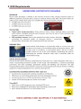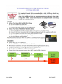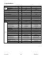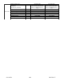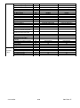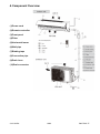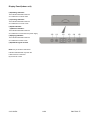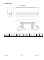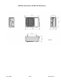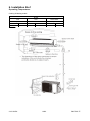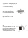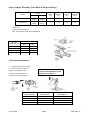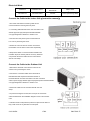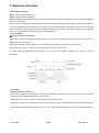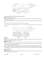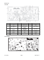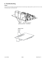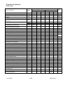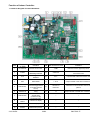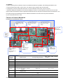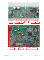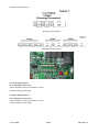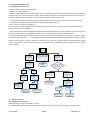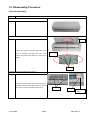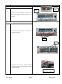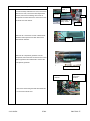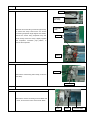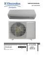
1
SERVICE MANUAL AIR CONDITIONER Electrolux Home Products Italy S.p.A. Corso Lino Zanussi, 30 I - 33080 Porcia – PN Fax: + 39 0434 394096 SOE Edition: 07-2012 Rev 0.0 Publication number 599 75 60-77 EN INVERTER SPLIT SYSTEM AIR CONDITIONER MODEL: EXH09HL1W EXH12HL1W 2010-10 ADL 2/62 599 73 60-74 Index 1. Safety Precautions: refer to Page 3. 2. ESD Requirements: refer to Pages 4 & 5. 3. Specifications: refer to Pages 6 to 7. 4. Component Overview: refer to Pages 8 & 9. 5. Dimention: refer to Pages 10 & 11. 6. Installation Brief: refer to Pages 12 to 15 7. Electrical Functions: refer to Pages 16 to 23. 8. Schematic Diagram: refer to Pages 24 to 27. 9. Troubleshooting: refer to Pages 28 to 52. 10. Disassembly Precedure: refer to Pages 53 to 60. 210-10 ADL 3/62 599 75 60-77 1. Safe Electrical Working Practices: Isolate Power Before Attempting to Service any Appliance. Remove Power cord, Fuse or Switch off the Circuit Breaker. Always check appliance with multimeter to ensure the power is disconnected. If you have to work on a live appliance all precautions must be taken. Use only Insulated tools and equipment. Wear insulated shoes. No water on the floor or working space. Reduce the amount of exposed skin, by covering your arms and legs. Remove jewelry (rings, watches etc). It is essential that you conform to all local "Working Live" and "Risk Management" statutory requirements. Duty of Care: The Appliance Must Be Electrically and Mechanically Safe To Use Always check appliance with Megga to before reconnecting the power supply. 210-10 ADL 4/62 599 75 60-77 2. ESD Requirements 210-10 ADL 5/62 599 75 60-77 210-10 ADL 6/62 599 75 60-77 3. Specifications Parameter Model Unit Rated Voltage Rated Frequency Phases Power Supply Mode Cooling Capacity (Min~Max) Heating Capacity (Min~Max) Cooling Power Input (Min~Max) Heating Power Input (Min~Max) Cooling Power Current Heating Power Current Rated Input Rated Current Air Flow Volume((SH/H/MH/M/L/ML/SL) Dehumidifying Volume EER COP SEER HSPF Application Area Model of indoor unit Fan Type Diameter Length(DXL) Fan Motor Cooling Speed (SH/H/MH/M/L/ML/SL) Fan Motor Heating Speed (SH/H/MH/M/L/ML/SL) Output of Fan Motor Fan Motor RLA Fan Motor Capacitor Input of Heater Evaporator Form Pipe Diameter Indoor Row-fin Gap Unit Coil Length (LXDXW) Swing Motor Model Output of Swing Motor Fuse Sound Pressure Level (SH/H/MH/M/L/ML/SL) Sound Power Level (SH/H/MH/M/L/ML/SL) Dimension (WXHXD) Dimension of Carton Box (LXWXH) Dimension of Package (LXWXH) Net Weight Gross Weight V~ Hz Power Supply 210-10 ADL W A Value EXH09HL1W 220-240 50 1 Indoor 2500(700~4400) 2600(720~4200) 485(170~1350) 500(182~1300) 2.10 2.20 1400 6.20 770/670/610/530/460/410/380 0.8 5.15 5.20 12-18 EXH09HL1WI Cross-flow Φ98X662 1350/1070/1000/900/ 800/700/500 1350/1150/1080/1030/ 980/900/850 15 0.07 Aluminum Fin-copper Tube Φ7 2-1.5 662X25.4X305 MP24HA/MP24HB/MP24HC 2.4/2.4/2.4 PCB 3.15A Value EXH12HL1W 220-240 50 1 Indoor 3500(700~4500) 4000(720~4800) 823(150~1450) 952(190~1500) 3.60 4.10 1700 7.5 770/670/610/530/460/410/380 1.4 4.25 4.20 16-24 EXH12HL1WI Cross-flow Φ98X662 1350/1070/1000/900/ 800/700/500 1350/1150/1080/1030/ 980/900/850 15 0.07 Aluminum Fin-copper Tube Φ7 2-1.5 662X25.4X305 MP24HA/MP24HB/MP24HC 2.4/2.4/2.4 PCB 3.15A dB (A) 43/36/34/32/28/24/22 43/36/34/32/28/24/22 dB (A) 55/48/46/44/40/36/34 55/48/46/44/40/36/34 mm 896X316X205 896X316X205 mm 950X385X280 950X385X280 mm kg kg 953X388X295 12.0 14.0 953X388X295 12.0 14.0 W W W W A A W A 3 m /h L/h W/W W/W W/W W/W 2 m mm r/min r/min W A μF W mm mm mm 7/62 599 75 60-77 Model of Outdoor Unit EXH09HL1WE CHINA RESOURCES(SHENYANG) SANYO COMPRESSOR CO. LTD EXH12HL1WE CHINA RESOURCES(SHENYANG) SANYO COMPRESSOR CO. LTD C-6RZ110H1A C-6RZ110H1A A A W FV50S Rotary 33 4.59 800 FV50S Rotary 33 4.59 800 1nt11l-3979 1nt11l-3979 ºC Electron expansion valve 16~30 Electron expansion valve 16~30 Compressor Manufacturer/Trademark Outdoor Unit Compressor Model Compressor Oil Compressor Type L.R.A. Compressor RLA Compressor Power Input Overload Protector Throttling Method Operation temp 210-10 ADL 8/62 599 75 60-77 Connectio n Pipe Ambient temp (cooling) Ambient temp (heating) Condenser Form Pipe Diameter Rows-fin Gap Coil Length (LXDXW) Fan Motor Speed Output of Fan Motor Fan Motor RLA Fan Motor Capacitor Air Flow Volume of Outdoor Unit Fan Type Fan Diameter Defrosting Method Climate Type Isolation Moisture Protection Permissible Excessive Operating Pressure for the Discharge Side Permissible Excessive Operating Pressure for the Suction Side Sound Pressure Level (H/M/L) Sound Power Level (H/M/L) Dimension (WXHXD) Dimension of Carton Box (LXWXH) Dimension of Package (LXWXH) Net Weight Gross Weight Refrigerant Refrigerant Charge Length Gas Additional Charge Outer Diameter Liquid Pipe Outer Diameter Gas Pipe Max Distance Height Max Distance Length 210-10 ADL ºC ºC 16~48 16~48 –20~+24 –20~+24 Aluminum Fin-copper Tube Φ7.94 2.5-1.5 762X57X550 T1 I IP24 Aluminum Fin-copper Tube Φ7.94 2.5-1.5 762X57X550 750/600 40 0.23 2000 Axial-flow Φ445 Automatic Defrosting T1 I IP24 MPa 4.3 4.3 MPa 2.5 2.5 dB (A) dB (A) mm 51/-/63/-/818X596X300 52/-/64/-/818X596X300 mm 945X417X630 945X417X630 mm kg kg 948X420X645 43 48 R410A 1.3 5 20 Φ6 Φ9.52 10 20 948X420X645 43 48 R410A 1.3 5 20 Φ6 Φ9.52 10 20 mm mm mm rpm W A μF 3 m /h 750/600 40 0.23 2000 Axial-flow Φ445 mm Automatic Defrosting kg m g/m mm mm m m 9/62 599 75 60-77 4.Component Overview (1)Power cord (2)Remote controller (3)Front panel (4)Fitter (5)Horizontal louver (6)Wall pipe (7)Binding tape (8)Connection pipe (9)Drain hose (10)Drain connecter 210-10 ADL 10/62 599 75 60-77 Display Panel(indoor unit) (10)Heating indicator: This indicator illuminates when the air conditioner is in HEAT mode. (11)Cooling indicator: This indicator illuminates when the air conditioner is in COOL mode (12)LED indicator (13)Power indicator: This indicator illuminates when the air conditioner is connected to the power supply. (14)Drying indicator: This indicator illuminates when the air conditioner is in DRY mode (15)Infrared signal receiver Note: Arry of the above-mentioned indicators will illuminate only when the LIGHT function is activated By the remote control. 210-10 ADL 11/62 599 75 60-77 5. Dimensions Indoor Unit Unit:mm Models W(R) D H EXH09HL1W EXH12HL1W 896 205 316 210-10 ADL H1 267 12/62 H2 H3 Q Q1 S S1 35 34.5 177 160 178 80 599 75 60-77 EXH09HL1W (outdoor) & EXH12HL1W(outdoor) 210-10 ADL 13/62 599 75 60-77 6. Installation Brief Operating Temperatures: Cooling & Heating models MODE Cool Temperature Heat Temperature Dehumidifier Temperature Indoor Outdoor Indoor Outdoor Indoor Outdoor 16°C~30°C 16°C~48°C 16°C~30°C -20°C~24°C 16°C~30°C 16°C~48°C 210-10 ADL 14/62 599 75 60-77 Installation Site Instructions Proper installation site is vital for correct and efficient operation of the unit. Avoid the following sites where: ●strong heat sources, vapours, flammable gas or volatile liquids are emitted. ●high-frequency electro-magnetic waves are generated by radio equipment, ●welders and medical equipment. ●salt-laden air prevails (such as close to coastal areas). ●the air is contaminated with industrial vapours and oils. ●the air contains sulphures gas such as in hot spring zones. ●corrosion or poor air quality exists. Installation Site of Indoor Unit 1. The air inlet and outlet should be away from the obstructions. Ensure the air can be blown through the whole room. 2. Select a site where the condensing water can be easily drained out, and where it is easily connected for outdoor unit. 3. Select a place where it is out of reach of children. 4. Select the place where the wall is strong enough to With stand the full weight and vibration of the unit. 5. Be sure to leave enough space to allow access for routine maintenance. The installation site should be 250cm or more above the floor. 6. Select a place about 1m or more away from TV set or any other electric appliance. 7. Select a place where the filter can be easily taken out. 8. Make sure that the indoor unit is installed in accordance with installation dimension instructions. 9. Do not use the unit in the laundry or by swimming pool etc. Installation Site of Outdoor Unit 1.Select a site where noise and outflow air emitted by unit will not annoy neighbors. 2.Select a site where there is sufficient ventilation. 3.Select a site where there is no obstruction blocking the inlet and outlet. 4.The site should be able to withstand the full weight and vibration. 5.Select a dry place, but do not expose the unit to direct sunlight or strong wind. 6.Make sure that the outdoor unit is installed in accordance with the installation instructions,and is convenient for maintenance and repair. 7.The height difference between indoor and outdoor units is within 10 m, and the length of the connecting tubing does not exceed 20 8.Select a place where it is out of reach of children. 9.Select a place which will not block pedestrian passage and influence the city appearance. 210-10 ADL 15/62 599 75 60-77 Piping Length, Elevation, Flare Work & Torque Settings Piping Model Standard Length (m) Max Elevation (m) Max Length (m) Additional Refrigerant (g/m) GAS LIQUID EXH09HL1W 3/8 9.52mm 1/4 6.00mm 5 10 20 20 EXH12HL1W 3/8 9.52mm 1/4 6.00 mm 5 10 20 20 Flaring work. Firmly hold copper pipe in a die in the dimension shown in The table below . A(mm) OUTER DIAMETER(mm) Max. Min. 6,00 1,3 0,7 9,52 1,6 1,0 12,70 1,8 1,0 16 2,4 2,2 Connection Adjustment 1. Align the pipes to be connected. 2. Screw the flare nut with your Caution:Excessive twisting may break the nut,depending on the installation conditions. fingers,and the tighten it with a spanner and torque wrench, as shown in the following figure. 210-10 ADL OUTER DIAMETER(mm) TIGHTENING TORQUE(N/cm) ADITINAL TIGHTENING TORQUE(N/cm) 6,00 1570(160 kgf/cm) 1960(200 kgf/cm) 9,52 2940(300 kgf/cm) 3430(350 kgf/cm) 12,70 4900(500 kgf/cm) 5390(550 kgf/cm) 16 6000(611 kgf/cm) 6500(663 kgf/cm) 16/62 599 75 60-77 Electrical Work: CAPACITY POWER SUPPLY INPUT RATED AMP Switch/Fuse CABLE SIZE EXH09HL1W EXH12HL1W 220-240V~/50Hz 16A/16A 1.5 mm (power cord) 2 1.5 mm (connecting cable) 2 Connect the Cable to the Indoor Unit(instruction manual) 1.The inside and outside connecting cable can be connected without removing the front panel. 2. Connecting cable between indoor unit and outdoor unit shall be approved polychloroprene sheathed flexible cord,type designation H07RN-F or heavier cord. 3.Life the indoor unit panel up,remove the electrical box cover by loosening the screw. 4.Ensure the colour of wires of outdoor unit and the terminal Nos. are the same to the indoor respectively. 5.Wrap those cables not connected with terminals with insulation tapes,so that they will not touch any electrical components.Secure the cable onto the control board with the cord clamp. Connect the Cable to the Outdoor Unit 1.Remove the electrical control board cover from the outdoor unit by loosening the screw. 2.Connect the connective cables to the terminals as Identified with their respective matched numbers on the terminal block of indoor and outdoor unit.The connective cable to power supply shall be approved polychloroprene sheathed flexible cord,type designation H07RN-F or heavier cord. 3.Securd the cable onto the control board with the cord clamp. 4.To prevent the ingress of water,form a loop of the connective cable as illustrated in the installation diagram of indoor and outdoor units. 5.Insulate unused cord(conductors) with PVC-tape.Process them so they could not touch any electrical or metal parts. 210-10 ADL 17/62 599 75 60-77 7. Electronic Function 1.Temperature Parameters ◆Indoor preset temperature (Tpreset) ◆Indoor ambient temperature (Tamb.) 2.Basic Functions (The temperature in this manual is expressed by Centigrade. If Fahrenheit is used, the switchover between them is Tf=TcX1.8+32.) Once the unit is energized, the compressor shall never be restarted except 3mins interval at least. For the first energization, if the unit is at off status before power failure, the compressor can be restarted without 3-min delay. But if the unit is at ON status before power failure, the compressor shall be restarted with 3mins delay. Once the compressor is started up, the compressor won't stop running within 6mins with the change of room temperature. (1)Cooling Mode ①Cooling Conditions and Process When Tamb. ≥Tpreset, the unit starts cooling operation. In this case, the compressor and the outdoor fan operate and the indoor fan operates at set speed. When Tamb. ≤Tpreset-3℃, the compressor and the outdoor fan stop while the indoor fan runs at set speed. When Tpreset-3℃<Tamb. <Tpreset, the unit will maintain its previous running status. In cooling mode, the temperature setting range is 16 ~30℃; Indoor unit displays operation icon, cooling icon and set temperature. (2) Dry Mode ①Drying Conditions and Process When Tamb.>Tpreset, the unit operates in cooling mode. Meanwhile, compressor and outdoor fan operate, and indoor fan operates at set fan speed (low fan speed, quiet fan speed). When Tpreset-3℃<Tamb. ≤Tpreset, the unit keeps previous operation status. When Tamb. ≤Tpreset-3℃, compressor, outdoor fan and indoor fan operate at set fan speed (low fan speed, quiet fan speed). Under this mode, the temperature setting range is 16~30℃. Display displays operation icon, drying icon and set temperature. 210-10 ADL 18/62 599 75 60-77 (3) Heating Mode (this mode isn’t available for cooling only unit) ①Heating Conditions and Process When Tamb. ≤Tpreset+2℃, the unit operates in cooling mode. Compressor and outdoor fan operate and indoor fan operates according to cold air prevention. When Tamb.≥Tpreset+5℃, compressor and outdoor fan stop operation, while indoor fan operates according to blowing residual heat. When Tpreset+2℃<Tamb.<Tpreset+5℃, the unit operate at previous running status. In heating mode, the temperature setting range is 16~30℃; Indoor unit displays operation icon, cooling icon and set temperature. ②Defrosting When there’s too much frost on outdoor condenser, the complete unit will enter into defrosting automatically to assure the best heating effect. During defrosting process, H1 is displayed. ③Blow Residual Heat When heating temperature reaches to the temperature point of stop operation, compressor and outdoor fan will stop operation. The big horizontal louver rotates to the defaulted position in cooling and small horizontal louver will close. Indoor fan will stop operation after operating at set fan speed for 60s. When the unit operates in heating or auto heating mode, compressor is started up and the unit will stop operation after indoor fan starts operation. Compressor and outdoor fan stop operation. The big horizontal louver will rotate to the position of breeze (defaulted position in cooling), while the small horizontal louver will close. The unit will stop operation after indoor fan operates at low fan speed for 10s. ④Cold Air Prevention In heating mode, in order to prevent the cold air comes out when turning on the compressor, the indoor fan can only be started up after compressor operates for 2 minutes. 210-10 ADL 19/62 599 75 60-77 (4) Fan Mode In fan mode, indoor fan operates at set fan speed, while compressor and outdoor fan all stop operation. In fan mode, the temperature setting range is 16~30℃. Display is displaying operation icon and set temperature. (5) Auto Mode In auto mode, the system will select the operation mode (cooling, hearing of fan mode) according to the change of ambient temperature automatically. The display displays operation icon, actual operation mode and set temperature. 30s will be delayed for protection during mode switchover. Protection function is the same as that in other modes. The selection method for auto operation mode in details is as below: a. When Tamb. ≥26℃, the unit operates in cooling mode. The defaulted set temperature is 25℃; b. When Tamb. ≤21℃, the unit operates in heating mode. The defaulted set temperature is 20℃ (if it’s the cooling only unit that operates in fan mode, the defaulted set temperature is 25℃); c. When 22℃≤Tamb.≤25℃, if the unit is turned on for the first time, it will operate in auto fan mode; if the unit is switched to auto mode from other mode, it will keep previous operation mode; if the unit is switched to auto mode from dry mode, it will operates in fan mode. d. When the unit operates in auto mode, frequency of compressor during cooling and heating is same as that in cooling mode and heating mode respectively. Protection function: a. It’s the same as that in cooling mode when it operates in cooling; b. It’s the same as that in heating ode when it operates in heating; (6) 8℃ Heating Function In heating mode, press IONFilter+clock buttons on remote controller simultaneously. In this mode, “cold air prevention protection” will be shielded. ① 8℃ heating mode and sleep function can’t be set at the same time. If 8℃ heating mode has been set, press sleep button will cancel 8℃ heating mode. The set temperature value is the set temperature before entering the 8℃ heating mode. If sleep function has been set, press IONFilter+clock button on remote controller simultaneously to set 8℃ heating mode, meanwhile, sleep function will be canceled. ②Set temperature is 8℃; Indoor fan displays 8℃. ③In this mode, turbo function can be set and fan speed can’t be adjusted as well. ④In this mode, when compressor is operating, fan speed will be adjusted according to below auto fan speed; When compressor stops operation, indoor fan operates at blowing residual heat. When Tindoor amb. ≤9℃, indoor fan operates at high fan speed; When 9℃<Tindoor amb.<11℃, indoor fan operates at medium fan speed; When Tindoor amb.≥11℃, indoor fan operates at low fan speed; As for the switchover among high speed, medium speed and low speed, the unit should operate at every speed for 3minutes and 30s at least. Others are same as that in heating mode. ⑤The unit with memory function can memorize 8℃ heating mode. 210-10 ADL 20/62 599 75 60-77 (7)SAVE Function ① In cooling mode, if press IONFilter+clock buttons on remote controller simultaneously, the controller will enter into SAVE mode. In SAVE mode, if press IONFilter+clock buttons on remote controller simultaneously again, SAVE function won’t be set again. ②If remote controller is set to display set temperature, dual-8 nixie tube display “SE”. ③ In this mode, when compressor is operating, fan speed will be adjusted according to below auto fan speed in SAVE mode; When compressor stops operation, indoor fan operates at low fan speed. a. When Tamb. ≥31℃, indoor fan operates at super-high fan speed; b. When 31℃>Tamb.≥Tpreset+3℃, indoor fan operates at high fan speed; c. When Tpreset+1℃<Tamb.<Tpreset+3℃, indoor fan operates at medium fan speed; d. When Tamb.≤Tpreset+1℃, indoor fan operates at low fan speed; As for the switchover among super-high speed, high speed, medium speed and low speed, the unit should operate at every speed for 3minutes and 3s at least. ④In this mode, set temperature will be adjusted automatically according to actual operation status. 3 Other Control (1) Timer Function General timer and clock timer functions are compatible by equipping remote controller with different functions. ①General Timer Timer ON can be set at unit OFF. If selected ON time is reached, the unit will start to operate according to previous setting status. Time setting range is 0.5-24hr in 30-minute increments. Timer OFF can be set at unit ON. If selected OFF time is reached, the unit will stop operation. Time setting range is 0.5-24hr in 30-minute increments. ②Clock Timer (it’s optional for the remote controller with clock timer) Timer ON If timer ON is set during operation of the unit, the unit will continue to operate. If timer ON is set at unit OFF, upon ON time reaches the unit will start to operate according to previous setting status. Timer OFF If timer OFF is set at unit OFF, the system will keep standby status. If timer OFF is set at unit ON, upon OFF time reaches the unit will stop operation. 210-10 ADL 21/62 599 75 60-77 Timer Change Although timer has been set, the unit still can be turned on/off by pressing ON/OFF button of the remote controller. You can also set the timer once again, and then the unit will operate according to the last setting. If timer ON and timer OFF are set at the same time during operation of the unit, the unit will keep operating at current status till OFF time reaches. If timer ON and timer OFF are set at the same time at unit OFF, the unit will keep off status till ON time reaches. Each day in future, the system will operate according to preset mode till OFF time reaches and stop operation till ON time reaches. If ON time and OFF time are the same, OFF command takes the priority. (2) Auto Button If this button is pressed, the unit will operate in AUTO mode and indoor fan will operate at auto speed; meanwhile, the swing motor operates. Press this button again to turn off the unit. (3) Buzzer Upon energization or availably operating the unit or remote controller, the buzzer will give out a beep. (4)Sleep Function In SLEEP mode, the unit will automatically select appropriate sleep curve to operate according to different temperature setting. (5) Turbo Function This function can be set in cooling or heating mode to quickly cool or heat the room. (6) X-fan Function ①X-fan function can be set in cooling or drying mode (X-fan function is unavailable in auto, heating or fan mode). When X-fan is ON, after pressing ON/OFF button to turn off the unit, indoor fan will still operates at low fan speed for 10 minutes before turn off the complete unit. Within 10 minutes, swing operates at original status, cold plasma and electrostatic dedusting is ON, while other loads are OFF. When X-fan is OFF, press ON/OFF button to turn off the complete unit. ② During X-fan operation, after pressing X-fan button, indoor fan stops operates immediately. Horizontal louver will close and cold plasma and electrostatic dedusting is OFF as well. (7) Control of Indoor Fan Indoor fan can be set at quiet, north 1, north 2, notch 3, notch 4, notch 5 and turbo. Meanwhile, the fan can operate at low speed, medium speed, high speed or turbo. It can also set at auto fan speed. When indoor fan operates in auto fan speed mode, the indoor fan will operate at high speed, medium speed, low speed or turbo according to the change of ambient temperature. ①In auto heating mode or normal heating mode, the auto fan speed operates according to below mode: When Tamb. <Tpreset-3℃, indoor fan operates at high speed; When Tpreset-3℃≤Tamb.<Tpreset+2℃, indoor fan operates at medium speed; When Tpreset+2℃≤Tamb.<Tpreset+4℃, indoor fan operates at low speed; When Tamb.≥Tpreset+4℃, indoor fan operates at quiet mode. Control drawing of auto fan in heating mode: ②Fan mode, cooling mode: In auto cooling mode or normal cooling mode, auto fan speed operates according to below mode: When Tamb.≥Tpreset+3℃, indoor fan operates at high speed; 210-10 ADL 22/62 599 75 60-77 When Tpreset<Tamb.<Tpreset+3℃, indoor fan operates at medium speed; When Tpreset-2<Tamb.≤Tpreset, indoor fan operates at low fan speed; When Tamb. ≤Tpreset-2℃, indoor fan operates at quiet mode. ③Auto fan speed is not available in drying mode Note: high speed, medium speed and low speed is to “notch 5”, “notch “3” and “notch 1” respectively. As for the switchover among high speed, medium speed and low speed, the unit should operates at every speed for 3minutes and 3s at least. (8) Control of Up&Down Swing a. Small Horizontal Louver After energization, small swing motor will firstly have the horizontal louver rotate anticlockwise to position 0 to close air outlet. If swing function has not been set after startup of the unit, horizontal louver will turn clockwise to position D1 in HEAT mode. If swing function is set when starting up the unit, the horizontal louver will swing between 0and D1. There are 7 swing status of horizontal louver: Positions O, A1, B1, C1, D1, swing between O and D1 and stop at any position between O and D1 (angles between O and D1 are equiangular mostly). In other statues, horizontal louver will close at position O. Upon turning off the unit, the horizontal louver will close at position 0. Swing is valid only when swing command is set and indoor fan operates. Note:1. If the position is set between O and D1, A1 and C1 or B1 and D1 by remote controller, the horizontal louver will swing between O and D1. 2. As for 9k/12k, only when the big horizontal louver rotates to he second swing angle position in heating (corresponding angle is 62º), the horizontal louver will start action. As for 18k, only when the big horizontal louver rotates to the first swing angle position in heating (corresponding angle is 64 º), the horizontal louver will start action. As for 24k, only when the big horizontal louver rotates to the first swing angle position in heating (corresponding angle is 40 º), the horizontal louver start action. 3. In cooling mode, the horizontal louver stops at position O all the time. b. Big Horizontal Louver After energization, up & down swing motor will firstly have the horizontal louver rotate anticlockwise to position 0 to close air outlet. If swing function has not been set after startup of the unit, horizontal louver will turn clockwise to position D in HEAT mode, or turn clockwise to level position L in other modes. If swing function is set when starting up the unit, the horizontal louver will swing between L and D. There are 7 swing status of horizontal louver: Positions L, A, B, C and D, swing between L and D and stop at any position between L and D (angles between L and D are equiangular). Upon turning off the unit, the horizontal louver will close at position 0. Note:1) If the position is set between L and B, A and C or B and D by remote controller, the horizontal louver will swing between L and D. 210-10 ADL 23/62 599 75 60-77 (9) Control of Left&Right Swing After energization, swing will be restored to the starting point firstly and then stop at the middle position. When setting left&right swing, swing blade has 7 statuses: left position ①, secondary left position ②, middle position ③, secondary right position ④, right position ⑤, swing between ①and ⑤, stop position. If left&right swing is set when turning on the unit, swing motor will drive blade to swing between left and right. When cancel left&right swing or swing hasn’t been set when turning on the unit for the first time, blade will stop at current position. Left&right swing will keep at original position when turning off the unit. Swing is valid only when swing command is set and indoor fan operates. (10) Display ①Operation and Mode Icons Upon energization within 3s, the unit will display all icons. Under standby state, running indicating mark is displayed. If the unit is started by remote controller, running indicating mark gives off light; meanwhile, the mark of current running mode will be displayed. If the light button is turned off, no mark will be displayed. ②Display of Nixie Tube on Indoor Unit When energized & started for the first time, the indoor unit defaults to displaying current set temperature (16~30℃). When set temperature display is set by remote controller, it will display set temperature; when room temperature display is set, it will display room temperature. After that, when operating the remote controller for other settings, the temperature display method will keep original. When operating the remote controller during room temperature display, the set temperature will be displayed for 5 seconds firstly and then room temperature display returns. “F1” will be displayed upon malfunction of room temperature sensor, “F2” upon malfunction of indoor unit tube temperature sensor and “C5” upon malfunction of jumper cap. (11) Memory Function Memorized items: mode, up & down swing, light, set temperature and set fan speed. When power is recovered after power failure, the unit will automatically start operation according to memorized status. After power recovery, the unit without timer setting before power failure will operate according to the last setting; the unit with general timer setting which has not been fulfilled before power failure will memorize the timer setting and re-calculate the time after power recovery. If there is timer function in the last remote controller command but setting time has reached, the system will act as timer on/off setting before power failure. After power failure, the system memorizes the operation states before power failure without timer action. Clock timer can not be memorized. (12) I FEEL Function When I FEEL command is received and controller has received the ambient temperature sent by remote controller, the controller will operate at the temperature sent by remote controller (For cold air prevention, the unit operates according to the ambient temperature sensed by the air conditioner). If it only received I FEEL command and hasn’t received the valid ambient temperature, air conditioner will operate according to the ambient temperature sensed by itself. Remote controller will send the ambient temperature to controller every 10min. If controller hasn’t received the ambient temperature sent by remote controller for 11min, air conditioner will operate according to the ambient temperature sensed y itself. If I FEEl hasn’t been set, ambient temperature will adopt the temperature sensed by air conditioner. Controller displays I FEEL ambient temperature 1℃~59℃。 (13)Health, Cold Plasma Function At ON status, press health button (if there isn’t health button on remote controller, health function is ON in default) on remote controller can set health or cold plasma function. Health or cold plasma function can operate when it set ON and indoor fan operates. 210-10 ADL 24/62 599 75 60-77 (14) Fahrenheit Display Function Niexie tube displays current set temperature. If the remote control signal is Fahrenheit, the temperature will be display by Fahrenheit. Set temperature range is 16~30℃(61-86℉). Under auto mode, nixie tube displays 25℃(77℉)in cooling and fan, and 20℃(68℉) in heating. Cooling only controller only displays 25℃(77℉). (15) Locked Protection to Indoor Fan If the indoor fan motor keeps low rotation speed for a continuous period of time after startup, the unit will stop operation and display “H6”. (16) Quiet Mode When quiet mode is set by remote controller, indoor fan will operate in quiet mode. (17) Compulsory Defrosting Function When the outdoor environment is formidable, such as temperature is too low and humidity is too high, and there is too much frost in outdoor unit which affect the heating effect, users can select compulsory defrosting function to outdoor unit’s heating effect. Compulsory defrosting function method: When the unit is turned on in heating mode by remote controller and the set temperature is 16℃, press “+、-、+、-、+、-” buttons for 5s successively, indoor unit will enter into compulsory defrosting setting and send the compulsory defrosting mode signal to outdoor unit and then outdoor unit will enter into compulsory defrosting mode. 210-10 ADL 25/62 599 75 60-77 8.Schematic Diagram 8.1 Electrical Wiring Indoor Unit Outdoor Unit Cooling & Heating Models 210-10 ADL 26/62 599 75 60-77 8.2 Printed Circuit Board Indoor Unit ●TOP VIEW SN Interface name SN 1 Health interface 7 2 Neutral wire interface 8 3 DC fan motor 9 4 Electrostatic dedusting interface 10 5 Inching switch interface 11 6 Auto button 12 210-10 ADL Interface name Small motor for vertical swing Horizontal swing Big motor for vertical swing Display interface Ambient temperature sensor Tube temperature sensor 27/62 SN 13 14 Interface name Indoor and outdoor communication port Outdoor power supply interface 15 Live wire interface 16 Fuse / / / / 599 75 60-77 ●BOTTOM VIEW 210-10 ADL 28/62 599 75 60-77 Outdoor Unit ●TOP VIEW SN Interface name 1 Input of neutral wire of power 6 2 Input of live wire of power 7 3 Communication interface 8 4 5 / Interface 1 of electric reactor Interface 2 of electric reactor / SN 9 10 Interface name Interface of fan Neutral wire of electric heater of chassis Neutral wire of electric heater of compressor Neutral wire of 4-way valve Live wire of 4-way valve / / SN Interface name 11 Live wire of electric heater 12 Input of overload 13 Temp sensor 14 15 16 U,V,W three phases of compressor Input of ground wire of power Input of Pressure switch ●BOTTOM VIEW 210-10 ADL 29/62 599 75 60-77 9. Troubleshooting Safety Please insure stored voltage is discharged/removed from all relevant high voltage capacitors, by the use of a 25 to 40 watt incandescent globe. As illustrated below. Electrolytic Capacitors (HIGH VOLTAGE! CAUTION!) Bulb (25-40W) 210-10 ADL 30/62 599 75 60-77 Diagnosis and Solution: Error Code Display of lamp (the times of blinking) Display of indoor unit Running Anti-freezing protection E2 2 System block or refrigerant leakage Compressor exhaust high temperature protection AC over-current protection E3 3 E4 4 7 P48 5 P45 Name of malfunction Indoor Cooling Page NO. Outdoor Heating Yellow Red Green 3 P45 9 P48 E5 5 Communication failure between indoor unit and outdoor unit E6 6 Anti-high temperature protection E8 H4 8 No feedback of indoor fan motor H6 11 Jumper cap malfunction protection C5 15 Indoor unit and outdoor unit doesn't match LP 19 16 Outdoor DC fan motor malfunction Power protection Gathering refrigerant L3 L9 Fo 23 20 1 9 Indoor ambient sensor open or short circuit F1 1 Indoor tube sensor open or short circuit F2 2 Outdoor ambient sensor open or short circuit F3 3 6 P46 Outdoor tube sensor open or short circuit F4 4 5 P46 Exhaust sensor open or short circuit F5 5 7 P46 Overload limit / drop frequency F6 6 3 Over current limit / drop frequency F8 8 1 High exhaust temperature limit / drop frequency F9 9 2 Anti-freezing limit / drop frequency FH 2 Defrosting H1 1 2 Compressor overload protection H3 3 8 P49 IPM protection H5 5 4 P47 PFC protection HC 6 14 P46 Loading EEPROM malfunction EE 15 11 P45 High PN voltage protection PH 13 P44 12 P44 Low PN voltage protection PL 4-way valve reversal abnormal U7 Compressor Min frequence in test state P0 Compressor rated frequence in test state P1 Compressor maximum frequence in test state P2 Compressor intermediate frequence in test state P3 Frequency limiting (power) LU Compressor is running(normal) The temperature for turning on the unit is reached(normal) Frequency limiting (module temperature ) 6 6 P35 P36 P37 P38 P47 1 P33 P34 2 21 4 20 P48 24 13 1 8 EU 6 31/62 P44 P39 P48 14 11 Normal communication 210-10 ADL OFF 6 11 continu ously 599 75 60-77 Function of Indoor Controller: 1. Interfaces Diagram of Indoor Mainboard S/N Silk screen on PCB Interface S/N Silk screen on PCB Interface 1 DC-MOTOR Interface of DC motor 11 TUBE Interface of indoor pipe temp sensor 2 CLEAN Electrostatic dedusting interface 12 COM-OUT 3 X10 Inching switch interface 13 AC-L Input terminal of live wire of indoor unit 4 KEY Auto button 14 L-OUT Output terminal of live wire of outdoor un 15 HEALTH-N HEALTH-L Interfaces for neutral and live wire of col plasma 16 N Input terminal of neutral wire of indoor un Output terminal of neutral wire of outdoor u / / / Interface of motor for vertical swing(interface for small horizontal louver) Interface for horizontal swing Interface of motor for vertical swing ( interface for big horizontal louver) Interface for communication between indo and outdoor units 5 SWING-UD1 6 SWING-LR 7 SWING-UD2 8 DISP1 DISP2 Interface for display / / / 9 JUMP Interface of jumper cap / / / 10 ROOM Interface of indoor ambient temp sensor / / / 210-10 ADL 32/62 599 75 60-77 2. Diagram of Display When the Unit is Standby 3. Troubleshooting of Indoor Unit 3.1 Malfunction Code Table of Indoor Unit 210-10 ADL 33/62 599 75 60-77 3.2 Each Troubleshooting and Schematic Diagram 3.2.1 Firstly, check if power supply is normal Check if power supply is normal and the voltage is between 165V~235V. 3.2.2 Refer to Malfunction Code Table and confirm the malfunction according to malfunction code displayed on indoor unit. F1,F2 Malfunctions Malfunction of indoor ambient temperature sensor: F1 is displayed; COOL LED lamp is off for 3s and blinks once; (That the LED lamp is on for 0.5s and off for 0.5s is a blink.) Malfunction of indoor pipe temperature sensor: F2 is displayed; COOL LED lamp is off for 3s and blinks twice; (That the LED lamp is on for 0.5s and off for 0.5s is a blink.) Resistance of indoor ambient temperature sensor: 15KΩ Resistance of indoor pipe temperature sensor: 20KΩ Reference voltage value of temperature sensor: 0VDC Diagram of Interfaces of Temperature Sensors: Indoor tube temp. sensor 210-10 ADL Temp. sensor reference voltage spot Indoor ambient temp. sensor 34/62 599 75 60-77 F1,F2 Malfunctions: Flowchart: Start Is the wiring terminal between temperature sensor and the controller loosened or poorly contacted? Yes Insert the temperature sensor tightly No Malfunction is eliminated No Is there short circuit due to tri-pover of the parts? Yes Make the parts upright No Malfunction is eliminated No Is the temperature sensor normal according to the Resistance Table? Yes No Replace it with a temperature sensor of the same model Yes Yes No Replace the controller with one of the same model Malfunction is eliminated Yes End 210-10 ADL 35/62 599 75 60-77 H6 Malfunction (2) Malfunction of Indoor Motor There is no feedback from indoor motor: H6 is displayed and LED lamp is off for 3s and blinks for 11 times. (That the LED lamp is on for 0.5s and off for 0.5s is a blink.) Interface of DC motor; 1.VDC DC power supply,normal working voltage: 280~310VDC; 2.Reference voltage point of GND DC motor; 3.Control voltage of Vcc DC motor: 15VDC; 4.Vsp voltage value is proportional to rotational speed; 5.Feedback voltage of Vpg DC motor is proportional to rotational speed; Diagram of Interfaces of DC Motor: 210-10 ADL 36/62 599 75 60-77 H6 Malfunction Flowchart: 210-10 ADL 37/62 599 75 60-77 C5 Malfunction (3) Malfunction of Jumper Cap Malfunction of Jumper Cap: C5 is displayed; Operation LED lamp is off for 3s and blinks for 15 times. (That the LED lamp is on for 0.5s and off for 0.5s is a blink.) Function of jumper cap: determine swing angle of different models and rotational speed of indoor fan. Interface Diagram of Jumper Cap: Jumper cap 210-10 ADL 38/62 599 75 60-77 C5 Malfunction Flowchart: C5 is displayed on the unit. Is there jumper cap on the controller? No Is the malfunction eliminated? Yes Is the jumper cap inserted incorrectly or improperly? No Install a matching jumper cap Yes No Re-insert the jumper cap Is the malfunction eliminated? Yes Replace the jumper cap Is the malfunction eliminated? Yes Yes No The mainboard is defined abnormal;replace it End 210-10 ADL 39/62 599 75 60-77 E6 Malfunction (4) Communication Malfunction between Indoor and Outdoor Units Communication malfunction between indoor and outdoor units: E6 is displayed and operation LED lamp is off for 3s and blinks for 6 times. (That the LED lamp is on for 0.5s and off for 0.5s is a blink.) When communication between indoor and outdoor units is normal, communication LED lamp of indoor unit blinks ( off for 0.5s and on for 0.5s). When correct signal has not been received for continuous 3 minutes, there is communication malfunction and communication LED lamp will be off. Diagram of Communication LED lamp of Indoor Unit: Indicator of communication signal Flowchart: Start Poor contact of any line may incur communication malfunction. Is communication wire reliably earthed? Is there any loose wire or poor contact? Yes Connect communication wire correctly. Is malfunction eliminated? Yes Is malfunction eliminated? Yes Is malfunction eliminated? Yes No No Do the mainboard mismatch display board or are mainboards of IDU and OUD mismatched? No Is there any wrong wire connection? Yes Assemble matched controller No Correct wire connection No No Replace controller 210-10 ADL End 40/62 599 75 60-77 4. Cautions: (1) Before replacing indoor mainboard, check if the substituted mainboard is qualified. The following tests shall be done: a. Test if protective tube FUSE1 is open-circuit. If so, replace it with a protective tube of same model. b. Energize the unit to test if the buzzer will sound. If not, this mainboard of the indoor unit can’t be used. c. Equip the display and energize the unit to test if the display is normal. If not, that mainboard of indoor unit can’t be used. (2)The model of the mainboard used for replacement shall be the same as the previous mainboard which has malfunction. And the model of jumper cap assembled for the new mainboard shall also be the same as that of previous mainboard. (3) The wiring shall also be the same. Function of Outdoor Mainboard Introduction to each Detection Point Rectify filtering circuit Detection point: rectify voltage DC motor control circuit Detection point: output voltage 4-way valve control circuit Detection point: output voltage Heavy current filter circuit Detection point: voltage after filtering PFC circuit Detection point: generatrix voltage Power on-off circuit Detection point: chip:5V PFC AND IPM:15V Relay:12V No. of Detection point Point 1 Compressor driver circuit Detection point: Up/Un, Vp/Vn, Wp/Wn, voltage waveform, 3-phase current waveform Temperature input circuit Detection point: IC insert voltage Detection point Between AC-L1,N1 Communication circuit Detection point: communication Corresponding parameter Test value under normal conditions Neutral and live wire 165 V ~ 253 V Point 2 Left side of R201;U404 heat sink DC bus bar 230 V ~ 380 V Point 3 Top of D304;bottom of D304 IPM drive voltage+15V 13.5 V ~15.5 V Point 4 Top of C116; bottom of C116 Relay drive voltage+12V 11 V ~13 V Point 5 Right side of R228; left side of R228 Two pins on upper left of U4; bottom of U4 (the top is close to “U4”silk screen) Two pins on upper left of U4; Bottom of U4 PFC drive voltage+15V 13.5 V ~15.5 V Chip+3.3V 3.1 V ~3.3 V +5V 4.8 V ~5.1 V Point 6 Point 7 Point 8 Bottom of R506; bottom of U4 Point 9 Bottom of R523; bottom of U4 Signal is received by outdoor unit Signal is sent by outdoor unit Point 10 Between AC-L2/4V Neutral and live wire 210-10 ADL 41/62 Between 0 and 3.3V Between 0 and 3.3V 165 V ~ 253 V 599 75 60-77 Detection point 5 Detection point 6 210-10 ADL Detection point 3 Detection point 2 Detection point 7 42/62 Detection point 10 Detection point 8 Detection point 4 Detection point 1 Detection point 9 599 75 60-77 3. Troubleshooting of Outdoor Unit 3.1 Firstly, check if power supply is normal Check if power switch is turned on and the voltage is between 165V~253V. 3.2 Malfunction Code Table of Outdoor Unit Malfunction Name Nixie Tube Freeze Protection E2 IPM protection H5 Overcurrent protection E5 EEPROM reading and writing malfunction EE Low voltage protection PL High voltage protection PH PFC overcurrent protection Mismatching of models of indoor and outdoor units Malfunction of outdoor ambient temperature sensor Malfunction of outdoor pipe temperature sensor Malfunction of outdoor discharge temperature sensor Communication malfunction Low pressure protection(refrigerant leak) Abnormality of 4-way valve Over-load protection HC LP Yellow LED Lamp Blinks for 3 times Blinks for 4 times Blinks for 5 times Blinks for 11 times Blinks for 12 times Blinks for 13 times Blinks for 14 times Blinks for 16 times LED Lamp Red LED Lamp F3 Blinks for 6 times F4 Blinks for 5 times F5 Blinks for 7 times Green LED Lamp 灭 E6 Blinks for 9 times E3 U7 E8 Discharge temperature protection E4 Overload protection H3 Over power protection L9 Blinks for 6 times Blinks for 7 times Blinks for 8 times Blinks for 9 times 3.3 Each Malfunction and Diagram (1) LED Lamp Status Description Different status of green, red and yellow indicators indicate different operation status and protection of the unit. Note:The LED’s flash at a 1 second rate for the required number of flashes, and then a 2 second pause before repeating the 1 second rate sequence. Note: Two or more faults can appear in the one LED fault sequence. 210-10 ADL 43/62 599 75 60-77 # Example of LED sequence: Single fault code sequence. Mutable fault code sequence. (2) Low Voltage protection PL is displayed on indoor unit Yellow LED lamp of outdoor unit blinks for 12 times # Check voltage of power supply. (3) High voltage protection PH is displayed on indoor unit Yellow LED lamp of outdoor unit blinks for 13 times. # Check voltage of power supply. 210-10 ADL 44/62 599 75 60-77 (4) Communication Malfunction E6 is displayed on indoor unit Green LED lamp of outdoor unit doesn’t blink. # If there is no LED lamp blinking, 1. Measure voltage between N1 (neutral wire ) and 3 (live wire) on patching board of outdoor electric box by AC voltage grade of universal meter. If it is found that there is voltage, check if there is electricity for patching board of indoor unit. If there is no electricity, check if wiring of indoor unit is correct. Otherwise replace controller of indoor unit. 2. If power supply of indoor unit is normal, check if wiring of outdoor unit is correct and if there is any wrong or loose wiring. 3. If the above two conditions don’t exist, outdoor controller can be replaced directly. # Any or a few of indicators are normally on, Such circumstance usually indicates that IC on outdoor controller doesn’t work. Outdoor controller can be replaced directly. # There is only red indicator blinking 1. Set universal meter to DC voltage grade to measure voltage of detection point 8. If voltage is between 0~3.3V, the signal has been sent by indoor unit but not received by outdoor unit yet. In that case, replace outdoor controller directly. 2.If voltage of detection point 8 is always around 3.3V or around 0V, set universal meter to AC voltage to measure voltage between communication wire (2) and neutral wire (N1) on patching board. If voltage swings between 0V and 20V, the signal has been sent by indoor unit but not received by outdoor unit yet. In that case, replace outdoor controller directly. If voltage doesn’t change, indoor unit has not sent signal or the communication wire is damaged. Check communication wire or replace indoor controller. Communicati on malfunction Any LED lamp or a few of LED lamps are always on. Three LED lamps are all off Check voltages of neutral and live wire on patching board of ODU. Normal Voltage is between 0~ 3.3V Voltage is always at high level or always at low level. Replace outdoor controller directly. Measure voltage between communication wire and neutral wire on patching board with universal meter. Check if wiring or IDU is correct. Wiring is correct and replace the IDU. Wiring is correct and replace the outdoor controller. (5) Check voltage of detection point 8 by DC voltage grade of universal meter. Abnormal Check if wiring or ODU is correct. Wiring is wrong or loose and correct the wiring. Replace ODU directly. Only red LED lamp blinks Wiring is wrong or loose and correct the wiring. Voltage changes between 0V and 20V. Voltage doesn’t change Replace outdoor controller directly. Check communication wire or replace indoor controller. Freeze Protection E2 is displayed on indoor unit Yellow LED lamp of outdoor unit blinks for 3 times # It indicates that the temperature of indoor evaporator is too low so it is easily frozen. Check if indoor fan is operating. 210-10 ADL 45/62 599 75 60-77 (6) Over current protection E5 is displayed on indoor unit Yellow LED lamp of outdoor unit blinks for 5 times #It indicates that the current of the complete unit is too large. Check if voltage of power supply is normal. (7) EEPROM Reading and Writing Malfunction EE is displayed on indoor unit Yellow LED lamp of outdoor unit blinks for 11 times # Check if EEPRPM is assembled correctly. Position of EEPROM (8) Outdoor Ambient Temp. Sensor Malfunction F3 is displayed on indoor unit Red LED lamp of outdoor unit blinks for 6 times # Check if external ambient temp. sensor is well connected # Check if external ambient temp. sensor is open-circuit or short-circuit (9) Outdoor Tube Temp. Sensor Malfunction F4 is displayed on indoor unit Red LED lamp of outdoor unit blinks for 5 times # Check if external tube temp. sensor is well connected # Check if external tube temp. sensor is open-circuit or short-circuit (10) Outdoor Air Discharging Temp. Sensor Malfunction F5 is displayed on indoor unit Red LED lamp of outdoor unit blinks for 7 times # Check if the air discharging temp. sensor is well connected # Check if air discharging temp. resistance is open-circuit or short-circuit 210-10 ADL 46/62 599 75 60-77 (11) PFC Over Current Protection HC is displayed on indoor unit Yellow LED lamp of outdoor unit blinks for 14 times # Check if the power supply voltage is normal # Check if there is short circuit between any two pins. If so, IGBT is damaged. Replace the IGBT and turn on the unit again. If IGBT is still burnt out, the PFC drive circuit is damaged, replace the mainboard. # Check if voltage of PFC is normal (15V). If not, check switch power module. (12) IPM Protection H5 is displayed on indoor unit Yellow LED lamp of outdoor unit blinks for 4 times # Check if the compressor module is normal: check if it is short circuit of the outdoor unit mainboard bus bar (the left side of R201, see test point 2) and phase U, V, W, check if it is short circuit of earth wire (Radiator U404, see test point 2) and phase U, V, W, if so, the module is damaged. If not, check the AC with following steps IPM module protection occurs (H5 is displayed on indoor unit) Wait over 3min and ,check if the unit can resume normal operation. Unrecovera ble Recoverable Keep the unit operating and observe if IPM module protection will occur again. De-energize the unit and wait for over 5min and then energize it again( set COOL or HEAT mode). Observe if IPM protection occurs within 1min after turning on the unit. Y Over current protection occurs for power supply module incurs IPM module protection N Y Normal IPM protection which may be incurred by abnormal power supply or other reasons N After turning on the unit, observe if outdoor fan is operating (keep operating for about 1min and then stops operation) Because there are over 6 times of over current protection for IPM module, refer to recoverable conditions. N Y Check if power supply (15V, detection point 3) for IPM module is normal. Check if voltage of power supply is lower than 165V; If condenser is blocked; De-energize the unit and wait for at least 5min. Then open outdoor electric box to check if screws of IPM module are screwed up. And check if thermal grease is spread evenly. Normal Control terminal inside IPM module is damaged Clean condenser of outdoor unit; spread thermal grease on the bottom of IPM module; reassemble IPM module. 210-10 ADL Replace IPM module or mainboard Abnormal D304 or switch power board is damaged Y Replace D304 or mainboard 47/62 De-energize the unit and wait for at least 5min (when voltage between P and N is lower than 40V). Unplug U,V,W terminals connecting to compressor and check if IGBT on IPM is damaged by universal meter. N Replace IPM module or mainboard 599 75 60-77 Check if compressor is damaged or blocked. (13) Mismatching of indoor and outdoor unit LP is displayed on indoor unit Yellow LED lamp of outdoor unit blinks for 16 times # Check if jumper cap of indoor unit is applicable. Needle stand of jumper cap (14) Low Pressure Protection (refrigerant leak) (not applicable to this model) E3 is displayed on indoor unit Red LED lamp of outdoor unit blinks for 9 time # Check if refrigerant leaks and if connecting pipe is correctly connected. (15) Abnormality of 4-way valve U7 is displayed on indoor unit # If 4-way valve is abnormally working, check 4-way valve is damaged; cut-off power and unplug 2 wire of 4-way valve. Then measure resistance between two wire. If the resistance is not between 1~2K, the electromagnetic valve is open circuit. In that case, replace coil of 4-way valve. (16) Over-load Protection Function E8 is displayed on indoor unit Yellow LED lamp of outdoor unit blinks for 6 times. Measure temperature of outdoor heat exchanger during COOL operation; measuring temperature of indoor heat exchanger during HEAT operation. When Tpipe≤T1℃, the previous operation status will be resumed. When Tpipe≥T2℃, if Tpipe≤T1℃ for continuous 3min, normal operation will be resumed; When Tpipe≥T3℃, compressor will operate at decreased frequency; When Tpipe≥T4℃, compressor will stop operation; During COOL and DRY operations:T1=52,T2=55,T3=58,T4=62; During HEAT operation:T1=50,T2=53,T=56,T4=60; # Check if temperature of pipe meets the above conditions of over-load protection. 210-10 ADL 48/62 599 75 60-77 (17) Discharge Temperature Protection E4 is displayed on indoor unit Yellow LED lamp of outdoor unit blinks for 7 times When TBdischarge≥98℃, the frequency is prohibited to increase; When TBdischarge≥103℃, the compressor operates at decreased frequency; When TBdischarge≥110℃, the compressor stops operation; When TBdischarge≤90, when compressor has stopped operation for 3min, it will resume operation. # Check if discharge temperature meets the above conditions of protection. (18) Overload Protection H3 is displayed on indoor unit Yellow LED lamp of outdoor unit blinks for 8 times. # Check the following points: Refrigerant charge. Restrictions within the capillary tube. Poor air flow across the indoor & outdoor coils. Correct operation of the four way reversing valve. # Check the Compressor Over Temperature connector plug located on the outdoor PCB for correct termination & continuity to the over temperature protector. # Check the over temperature protector located next to the three compressor terminals. Note: This over temperature protector is “normally closed”. 210-10 ADL 49/62 599 75 60-77 (19) Power Protection L9 is displayed on indoor unit Yellow LED lamp of outdoor unit blinks for 9 times When Pc≥1900w, if Pc≤1800w for continuous 3min, the unit will resume normal operation; When PcB≥2000w, the unit will operate at decreased frequency; When Pc≥2100w, compressor stops operation. # Check if power of compressor meets the conditions mentioned above. Decrease the frequency so as to reduce the power to less than 1800w for 3min. Then check if the compressor resumes operation. (20) Other Normal Malfunction COOL operation is normal but HEAT operation is unavailable. COOL operation is normal but HEAT operation is unavailable. In HEAT mode, measure voltage between two wire of 4-way-valve by AC voltage grade of universal meter. If it is AC220V Voltage between 4V and AC-L2(detection point 10) is not around AC220V Cut-off power supply and unplug two wire of 4-way-walve. Then measure if resistance between the two wire is 1-2K Replace outdoor controller Resistance is too large Replace 4-way valve 4-way valve is normal The system of the unit is abnormal HEAT operation is normal but COOL operation is unavailable. It is usually due to K3 contact adhesion of outdoor controller, which can be judged by universal meter. 210-10 ADL 50/62 599 75 60-77 After replacing outdoor controller, the malfunction still exists: In that case, check if communication wire, temp sensor, fan, compressor or 4-way valve is normal. Communication wire: Check if communication wire, live wire and neutral wire are incorrectly connected, or wiring terminal is poorly connected. If the communication wire is prolonged, check if the joint is well connected. Temperature sensor: measure resistances to ground of the 3.3V(detection point 6) and IPM15V(detection point 3). If there is short circuit to ground, check if each temp sensor is damaged. Electric reactor: If communication malfunction still occurs after replacing electric box, unplug 2 wiring terminals of electric reactor and measure resistance between these two terminals by universal meter. Fan: unplug wiring terminal of fan and measure resistance between any two wire among red, yellow, white wire by universal meter. Usually, the resistance will be hundreds of ohm, otherwise, there is open circuit and the fan is damaged. Compressor: If operation environment is good, wiring is correct and system is in normal conditions, the H5 protection still frequently occurs after replacing controller, probably because compressor has malfunction. 4-way valve: unplug two purple wire of 4-way valve and then measure if resistance between these two wire is 1~2K. If the resistance is too large, there is open circuit of electromagnetic valve and coil of 4-way valve shall be replaced. If malfunctions above don’t exist, inspect indoor unit. (21) Cautions 1. Before replacing mainboard of inverter outdoor unit, check if the substituted mainboard is qualified. The following tests shall be done: a. Check if there is short circuit between any two pins of IGBT. If so, this mainboard of outdoor unit can’t be used. b. Check if there is short circuit between P,N of DC bus bar. If so, this mainboard of outdoor unit can’t be used. c. Check if there is short circuit between P and U,V,W and between N and U,V,W. If there is any short circuit, this mainboard can’t be used. 2. Each kind of compressor is applicable to one kind of mainboard. There is one-to-one relationship between mainboard and compressor. Before replacement, check the model of the mainboard which has malfunction and then use the mainboard with the same model for replacement. Don’t judge model of mainboard according to model of the unit, or else, mismatching between mainboard and compressor may be incurred. 3. Before replacing compressor, chosen compressor which has the same model for replacement. Don’t judge model of compressor according to model of the unit, or else, mismatching between compressor and pipeline or controller may be incurred. 4. Wire can’t contact each other, 4-way valve, compressor and sharp edge. Ground wire of compressor, fan and electric box shall be separately fixed. 210-10 ADL 51/62 599 75 60-77 Appendix Appendix 1: Resistance Table of Ambient Temperature Sensor for Indoor and Outdoor Units(15K) Resistance Resistance Temp(℃) Resistance(kΩ) Temp(℃) Temp(℃) Temp(℃) (kΩ) (kΩ) -19 138.1 20 18.75 59 3.848 98 Resistance (kΩ) 1.071 -18 128.6 21 17.93 60 3.711 99 1.039 -17 121.6 22 17.14 61 3.579 100 1.009 -16 115 23 16.39 62 3.454 101 0.98 -15 108.7 24 15.68 63 3.333 102 0.952 -14 102.9 25 15 64 3.217 103 0.925 -13 97.4 26 14.36 65 3.105 104 0.898 -12 92.22 27 13.74 66 2.998 105 0.873 -11 87.35 28 13.16 67 2.896 106 0.848 -10 82.75 29 12.6 68 2.797 107 0.825 -9 78.43 30 12.07 69 2.702 108 0.802 -8 74.35 31 11.57 70 2.611 109 0.779 -7 70.5 32 11.09 71 2.523 110 0.758 -6 66.88 33 10.63 72 2.439 111 0.737 -5 63.46 34 10.2 73 2.358 112 0.717 -4 60.23 35 9.779 74 2.28 113 0.697 -3 57.18 36 9.382 75 2.206 114 0.678 -2 54.31 37 9.003 76 2.133 115 0.66 -1 51.59 38 8.642 77 2.064 116 0.642 0 49.02 39 8.297 78 1.997 117 0.625 1 46.6 40 7.967 79 1.933 118 0.608 2 44.31 41 7.653 80 1.871 119 0.592 3 42.14 42 7.352 81 1.811 120 0.577 4 40.09 43 7.065 82 1.754 121 0.561 5 38.15 44 6.791 83 1.699 122 0.547 6 36.32 45 6.529 84 1.645 123 0.532 7 34.58 46 6.278 85 1.594 124 0.519 8 32.94 47 6.038 86 1.544 125 0.505 9 31.38 48 5.809 87 1.497 126 0.492 10 29.9 49 5.589 88 1.451 127 0.48 11 28.51 50 5.379 89 1.408 128 0.467 12 27.18 51 5.197 90 1.363 129 0.456 13 25.92 52 4.986 91 1.322 130 0.444 14 24.73 53 4.802 92 1.282 131 0.433 15 23.6 54 4.625 93 1.244 132 0.422 16 22.53 55 4.456 94 1.207 133 0.412 17 21.51 56 4.294 95 1.171 134 0.401 18 20.54 57 4.139 96 1.136 135 0.391 19 19.63 58 3.99 97 1.103 136 0.382 210-10 ADL 52/62 599 75 60-77 Appendix 2: Resistance Table of Outdoor and Indoor Tube Temperature Sensors(20K) Resistance Resistance Resistance Temp(℃) Temp(℃) Temp(℃) Temp(℃) (kΩ) (kΩ) (kΩ) Resistance (kΩ) -19 181.4 20 25.01 59 5.13 98 1.427 -18 171.4 21 23.9 60 4.948 99 1.386 -17 162.1 22 22.85 61 4.773 100 1.346 -16 153.3 23 21.85 62 4.605 101 1.307 -15 145 24 20.9 63 4.443 102 1.269 -14 137.2 25 20 64 4.289 103 1.233 -13 129.9 26 19.14 65 4.14 104 1.198 -12 123 27 18.13 66 3.998 105 1.164 -11 116.5 28 17.55 67 3.861 106 1.131 -10 110.3 29 16.8 68 3.729 107 1.099 -9 104.6 30 16.1 69 3.603 108 1.069 -8 99.13 31 15.43 70 3.481 109 1.039 -7 94 32 14.79 71 3.364 110 1.01 -6 89.17 33 14.18 72 3.252 111 0.983 -5 84.61 34 13.59 73 3.144 112 0.956 -4 80.31 35 13.04 74 3.04 113 0.93 -3 76.24 36 12.51 75 2.94 114 0.904 -2 72.41 37 12 76 2.844 115 0.88 -1 68.79 38 11.52 77 2.752 116 0.856 0 65.37 39 11.06 78 2.663 117 0.833 1 62.13 40 10.62 79 2.577 118 0.811 2 59.08 41 10.2 80 2.495 119 0.77 3 56.19 42 9.803 81 2.415 120 0.769 4 53.46 43 9.42 82 2.339 121 0.746 5 50.87 44 9.054 83 2.265 122 0.729 6 48.42 45 8.705 84 2.194 123 0.71 7 46.11 46 8.37 85 2.125 124 0.692 8 43.92 47 8.051 86 2.059 125 0.674 9 41.84 48 7.745 87 1.996 126 0.658 10 39.87 49 7.453 88 1.934 127 0.64 11 38.01 50 7.173 89 1.875 128 0.623 12 36.24 51 6.905 90 1.818 129 0.607 13 34.57 52 6.648 91 1.736 130 0.592 14 32.98 53 6.403 92 1.71 131 0.577 15 31.47 54 6.167 93 1.658 132 0.563 16 30.04 55 5.942 94 1.609 133 0.549 17 28.68 56 5.726 95 1.561 134 0.535 18 27.39 57 5.519 96 1.515 135 0.521 19 26.17 58 5.32 97 1.47 136 0.509 210-10 ADL 53/62 599 75 60-77 Temp(℃) -29 -28 210-10 ADL Appendix 3: Resistance Table of Outdoor Discharge Temperature Sensor(50K) Resistance Temp Resistance Temp Resistance Temp Resistance(kΩ) (kΩ) (℃) (kΩ) (℃) (kΩ) (℃) 853.5 10 98 49 18.34 88 4.754 799.8 11 93.42 50 17.65 89 4.609 -27 750 12 89.07 51 16.99 90 4.469 -26 703.8 13 84.95 52 16.36 91 4.334 -25 660.8 14 81.05 53 15.75 92 4.204 -24 620.8 15 77.35 54 15.17 93 4.079 -23 580.6 16 73.83 55 14.62 94 3.958 -22 548.9 17 70.5 56 14.09 95 3.841 -21 516.6 18 67.34 57 13.58 96 3.728 -20 486.5 19 64.33 58 13.09 97 3.619 -19 458.3 20 61.48 59 12.62 98 3.514 -18 432 21 58.77 60 12.17 99 3.413 -17 407.4 22 56.19 61 11.74 100 3.315 -16 384.5 23 53.74 62 11.32 101 3.22 -15 362.9 24 51.41 63 10.93 102 3.129 -14 342.8 25 49.19 64 10.54 103 3.04 -13 323.9 26 47.08 65 10.18 104 2.955 -12 306.2 27 45.07 66 9.827 105 2.872 -11 289.6 28 43.16 67 9.489 106 2.792 -10 274 29 41.34 68 9.165 107 2.715 -9 259.3 30 39.61 69 8.854 108 2.64 -8 245.6 31 37.96 70 8.555 109 2.568 -7 232.6 32 36.38 71 8.268 110 2.498 -6 220.5 33 34.88 72 7.991 111 2.431 -5 209 34 33.45 73 7.726 112 2.365 -4 198.3 35 32.09 74 7.47 113 2.302 -3 199.1 36 30.79 75 7.224 114 2.241 -2 178.5 37 29.54 76 6.998 115 2.182 -1 169.5 38 28.36 77 6.761 116 2.124 0 161 39 27.23 78 6.542 117 2.069 1 153 40 26.15 79 6.331 118 2.015 2 145.4 41 25.11 80 6.129 119 1.963 3 138.3 42 24.13 81 5.933 120 1.912 4 131.5 43 23.19 82 5.746 121 1.863 5 125.1 44 22.29 83 5.565 122 1.816 6 119.1 45 21.43 84 5.39 123 1.77 7 113.4 46 20.6 85 5.222 124 1.725 8 108 47 19.81 86 5.06 125 1.682 9 102.8 48 19.06 87 4.904 126 1.64 54/62 599 75 60-77 10. Disassembly Procedure Indoor disassembly: Procedure Steps 1. Before disassembly 2. Remove panel panel Remove the clamps on left and right side of the panel, to separate the panel and front case. displayer Remove the screws fixing display, to remove the display. screw 3. Remove filter and electric box cover 2 Loosen the clamp of filter, pull outward to remove the filter; remove the two fixing screws on electric box cover, to remove the electric box cover 2 210-10 ADL 55/62 filter screw electric box cover2 599 75 60-77 Steps Procedure 4. Remove guide louver axial bushing guide louver Pushing out the axial bushing in middle of the guide louver, slightly bend the guide louver to remove it. 5. Remove front case assy Remove the screws fixing front case. Loosen the clamps on front case. screw clamp Disconnect the connection terminal between electrostatic deduster and mainboard to remove the front case assy connection terminal of electrostatic deduster 210-10 ADL 56/62 599 75 60-77 6. Remove electric box assy electric box cover 1 Loosen the clasp of electric box cover; remove the electric box cover; remove the tube temperature sensor; remove the 3 earthing wire screws of earthin g screw scre w evaporator and then remove the connection screw of electric box and chassis. indoor tube temp. sensor clamp Remove the 2 connection screws of electrostatic deduster and evaporator and then remove the screw electrostatic deduster. Remove the cold plasma generator from the evaporator; disconnect the connection wire of cold plasma generator and mainboard to remove the cold plasma generator. 。 cold plasma generator motor connection terminal step motor connection terminal Disconnect each wiring terminal with mainboard to remove the electric box. 210-10 ADL 57/62 599 75 60-77 Steps Procedure 7. Remove connection pipe clamp and evaporator assy screw connection pipe clamp evaporator assy Remove the screws fixing connection pipe clamp, to remove the clamp. Remove the two screws connecting evaporator angle support and chassis, screw remove the screws fixing evaporator assy and motor clamp, loosen the clamp, slightly regulate the evaporator connection pipe position, to remove the evaporator. clamp 8. Remove motor clamp screw Remove the screws fixing motor clamp, to remove the clamp. motor clamp Steps Procedure 9. Remove motor and cross fan blade Remove the screws connecting cross fan blade and motor, to remove the motor and cross fan blade. motor 210-10 ADL 58/62 screw cross fan blade 599 75 60-77 Outdoor disassembly: Steps Procedure 1. Remove top cover Remove the screws fixing right handle and valve cover, to remove them. screw Remove the screws fixing left & right side of top cover, to remove the top cover. top cover screw 2. Remove panel assy panel assy Remove the screws connecting panel assy, chassis and motor support, to remove the panel assy. screw 210-10 ADL 59/62 599 75 60-77 3. Remove left and right side plate assy right side plate assy Remove the screws connecting right side plate and evaporator, electric box assy and valve support, to remove the right side plate assy. screw Left side plate assy Remove the screws connecting left side plate and evaporator to remove the left side plate assy. screw 4. Remove axial fan blade Remove the screw nut fixing axial fan blade, to remove the axial fan blade axial fan blade screw nut 210-10 ADL 60/62 599 75 60-77 5. Remove motor and motor support Remove the screw nut fixing motor, to remove the motor motor; remove the screws connecting motor support and chassis, to remove the motor support. motor support screw nut 6. Remove electric box assy electric box cover Remove the screw fixing electric box cover, to remove the electric box cover. Cut off the bonding tie, pull out every connection terminal, remove every connection wire along the wire distributing, to separate the connection wire electric box assy and electric box. Remove the screws connecting electric box assy, mid-isolation board and motor support, to remove the electric box assy. screw motor support 210-10 ADL 61/62 599 75 60-77 Steps Procedure 7. Remove four-way valve assy Remove the screw on electromagnetic loop, to four-way valve assy remove the loop. Welding cut the spot weld of four-way valve, to remove the four-way valve assy. (Release the refrigerant clearly before welding cutting) spot weld 8. Remove bid and small valve Remove the screw fixing big and small valve, to small valve screw remove the valves. big valve 9. Remove compressor compressor Remove the sound insulation cotton packing compressor, remove the feet screw nut fixing compressor, to remove the compressor. sound insulation cotton feet screw nut 210-10 ADL 62/62 599 75 60-77