1
Information
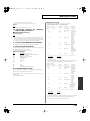
When you need repair service, call your nearest Roland Service Center or authorized Roland distributor in your country as
shown below.
EAST EUROPE
TAIWAN
Roland East Europe Ltd.
Warehouse Area ‘DEPO’ Pf.83
H-2046 Torokbalint, HUNGARY
TEL: (23) 511011
Room 5, 9fl. No. 112 Chung Shan
N.Road Sec.2, Taipei, TAIWAN,
R.O.C.
TEL: (02) 2561 3339
Roland Scandinavia As,
Filial Finland
Elannontie 5
FIN-01510 Vantaa, FINLAND
TEL: (0)9 68 24 020
NORWAY
AUSTRIA/BELGIUM/
FRANCE/GERMANY/
HOLLAND/
LUXEMBOURG/
PORTUGAL/SPAIN/
SWITZERLAND
SINGAPORE/
MALAYSIA
Roland Asia Pacific Sdn. Bhd.
45-1, Block C2, Jalan PJU 1/39,
Dataran Prima, 47301 Petaling
Jaya, Selangor, MALAYSIA
TEL: 3-7805-3263
Roland Iberia, S.L.
Paseo García Faria, 33-35
08005 Barcelona SPAIN
TEL: 93 493 91 00
CENTRAL/LATIN
AMERICA
DENMARK
Roland Scandinavia Avd.
Kontor Norge
Lilleakerveien 2 Postboks 95
Lilleaker N-0216 Oslo
NORWAY
TEL: 2273 0074
SWEDEN
Roland Scandinavia A/S
SWEDISH SALES OFFICE
Danvik Center 28, 2 tr.
S-131 30 Nacka SWEDEN
TEL: (0)8 702 00 20
UNITED KINGDOM/
IRELAND
Roland (U.K.) Ltd.
Atlantic Close, Swansea
Enterprise Park, Swansea
SA7 9FJ,
UNITED KINGDOM
TEL: (01792) 702701
OCEANIA
Roland Corporation
Australia Pty.,Ltd.
38 Campbell Avenue
Dee Why West, NSW 2099
AUSTRALIA
For Australia
TEL: (02) 9982 8266
For New Zealand
TEL: (09) 3098 715
NORTH AMERICA
CANADA
Roland Canada Ltd.
(Head Office)
5480 Parkwood Way, Richmond
B. C., V6V 2M4 CANADA
TEL: (604) 270 6626
Roland Canada Ltd.
(Toronto Office)
170 Admiral Boulevard
Mississauga ON L5T 2N6
CANADA
TEL: (905) 362 9707
U. S. A.
Roland Systems Group U.S.
425 Sequoia Drive Suite 114,
Bellingham, Washington,
98226 USA
TEL: 360-594-4282
Roland Scandinavia A/S
Nordhavnsvej 7, Postbox 880,
DK-2100 Copenhagen
DENMARK
TEL: 3916 6200
Roland Systems Group U.S.
425 Sequoia Drive Suite 114,
Bellingham, Washington,
98226 USA
TEL: 360-594-4282
OWNER’S MANUAL
ROLAND TAIWAN
ENTERPRISE CO., LTD.
FINLAND
AR-3000
EUROPE
ASIA
OWNER’S MANUAL
Before using this unit, carefully read the sections entitled: “USING THE UNIT SAFELY”
and “IMPORTANT NOTES” (p. 3; p. 5). These sections provide important information
concerning the proper operation of the unit. Additionally, in order to feel assured that
you have gained a good grasp of every feature provided by your new unit, OWNER’S
MANUAL should be read in its entirety. The manual should be saved and kept on hand as
a convenient reference.
As of August 1, 2006 (RSS)
234
* CompactFlash and
association.
are trademarks of SanDisk Corporation and licensed by CompactFlash
235
* Roland Corporation is an authorized licensee of the CompactFlash™ and CF logo (
marks.
) trade-
202
04236567
*
0
4
2
3
6
5
6
7
-
0
2
*
06-10-2N
Copyright © 2006 ROLAND CORPORATION
All rights reserved. No part of this publication may be reproduced in any form without the
written permission of ROLAND CORPORATION.
WARNING: To reduce the risk of fire or electric shock, do not expose this apparatus to rain or moisture.
The lightning flash with arrowhead symbol, within an
equilateral triangle, is intended to alert the user to the
presence of uninsulated “dangerous voltage” within the
product’s enclosure that may be of sufficient magnitude to
constitute a risk of electric shock to persons.
CAUTION
RISK OF ELECTRIC SHOCK
DO NOT OPEN
ATTENTION: RISQUE DE CHOC ELECTRIQUE NE PAS OUVRIR
CAUTION: TO REDUCE THE RISK OF ELECTRIC SHOCK,
DO NOT REMOVE COVER (OR BACK).
NO USER-SERVICEABLE PARTS INSIDE.
REFER SERVICING TO QUALIFIED SERVICE PERSONNEL.
The exclamation point within an equilateral triangle is
intended to alert the user to the presence of important
operating and maintenance (servicing) instructions in the
literature accompanying the product.
INSTRUCTIONS PERTAINING TO A RISK OF FIRE, ELECTRIC SHOCK, OR INJURY TO PERSONS.
IMPORTANT SAFETY INSTRUCTIONS
SAVE THESE INSTRUCTIONS
WARNING - When using electric products, basic precautions should always be followed, including the following:
1.
2.
3.
4.
5.
6.
7.
8.
9.
Read these instructions.
Keep these instructions.
Heed all warnings.
Follow all instructions.
Do not use this apparatus near water.
Clean only with a dry cloth.
Do not block any of the ventilation openings. Install in
accordance with the manufacturers instructions.
Do not install near any heat sources such as radiators,
heat registers, stoves, or other apparatus (including
amplifiers) that produce heat.
Do not defeat the safety purpose of the polarized or
grounding-type plug. A polarized plug has two blades with
one wider than the other. A grounding type plug has two
blades and a third grounding prong. The wide blade or the
third prong are provided for your safety. If the provided plug
does not fit into your outlet, consult an electrician for
replacement of the obsolete outlet.
10. Protect the power cord from being walked on or pinched
particularly at plugs, convenience receptacles, and the
point where they exit from the apparatus.
11. Only use attachments/accessories specified
by the manufacturer.
12. Unplug this apparatus during lightning storms or when
unused for long periods of time.
13. Refer all servicing to qualified service personnel. Servicing
is required when the apparatus has been damaged in any
way, such as power-supply cord or plug is damaged, liquid
has been spilled or objects have fallen into the apparatus,
the apparatus has been exposed to rain or moisture, does
not operate normally, or has been dropped.
For EU Countries
This product complies with the requirements of European Directives EMC 89/336/EEC and LVD 73/23/EEC.
For the USA
FEDERAL COMMUNICATIONS COMMISSION
RADIO FREQUENCY INTERFERENCE STATEMENT
For the U.K.
IMPORTANT: THE WIRES IN THIS MAINS LEAD ARE COLOURED IN ACCORDANCE WITH THE FOLLOWING CODE.
BLUE:
NEUTRAL
BROWN: LIVE
As the colours of the wires in the mains lead of this apparatus may not correspond with the coloured markings identifying
the terminals in your plug, proceed as follows:
The wire which is coloured BLUE must be connected to the terminal which is marked with the letter N or coloured BLACK.
The wire which is coloured BROWN must be connected to the terminal which is marked with the letter L or coloured RED.
Under no circumstances must either of the above wires be connected to the earth terminal of a three pin plug.
This equipment has been tested and found to comply with the limits for a Class B digital device, pursuant to Part 15 of the
FCC Rules. These limits are designed to provide reasonable protection against harmful interference in a residential
installation. This equipment generates, uses, and can radiate radio frequency energy and, if not installed and used in
accordance with the instructions, may cause harmful interference to radio communications. However, there is no guarantee
that interference will not occur in a particular installation. If this equipment does cause harmful interference to radio or
television reception, which can be determined by turning the equipment off and on, the user is encouraged to try to correct the
interference by one or more of the following measures:
– Reorient or relocate the receiving antenna.
– Increase the separation between the equipment and receiver.
– Connect the equipment into an outlet on a circuit different from that to which the receiver is connected.
– Consult the dealer or an experienced radio/TV technician for help.
This device complies with Part 15 of the FCC Rules. Operation is subject to the following two conditions:
(1) This device may not cause harmful interference, and
(2) This device must accept any interference received, including interference that may cause undesired operation.
Unauthorized changes or modification to this system can void the users authority to operate this equipment.
This equipment requires shielded interface cables in order to meet FCC class B Limit.
For the USA
DECLARATION OF CONFORMITY
Compliance Information Statement
Model Name :
Type of Equipment :
Responsible Party :
Address :
Telephone :
2
AR-3000R
Audio Recorder
Roland Systems Group U.S.
14830 Desman Road, La Mirada, CA 90638 U.S.A.
TEL: 714-521-8000
For Canada
NOTICE
This Class B digital apparatus meets all requirements of the Canadian Interference-Causing Equipment Regulations.
AVIS
Cet appareil numérique de la classe B respecte toutes les exigences du Règlement sur le matériel brouilleur du Canada.
AR-3000R_e2.book 3 ページ 2006年9月19日 火曜日 午前11時9分
USING THE UNIT SAFELY
The
symbol alerts the user to important instructions
or warnings.The specific meaning of the symbol is
determined by the design contained within the
triangle. In the case of the symbol at left, it is used for
general cautions, warnings, or alerts to danger.
Used for instructions intended to alert
the user to the risk of death or severe
injury should the unit be used
improperly.
Used for instructions intended to alert
the user to the risk of injury or material
damage should the unit be used
improperly.
* Material damage refers
other adverse effects
respect to the home
furnishings, as well
animals or pets.
The
symbol alerts the user to items that must never
be carried out (are forbidden). The specific thing that
must not be done is indicated by the design contained
within the circle. In the case of the symbol at left, it
means that the unit must never be disassembled.
to damage or
caused with
and all its
to domestic
The ● symbol alerts the user to things that must be
carried out. The specific thing that must be done is
indicated by the design contained within the circle. In
the case of the symbol at left, it means that the powercord plug must be unplugged from the outlet.
..........................................................................................................
..........................................................................................................
001
008a
• Before using this unit, make sure to read the
instructions below, and the Owner’s Manual.
• The unit should be connected to a power supply
only of the type described in the operating
instructions, or as marked on the side of unit.
..........................................................................................................
..........................................................................................................
002b
• Do not open or perform any internal modifications on the unit. (The only exception would be
where this manual provides specific instructions
which should be followed in order to put in place
user-installable options; see p. 15.)
..........................................................................................................
003
• Do not attempt to repair the unit, or replace parts
within it (except when this manual provides
specific instructions directing you to do so). Refer
all servicing to your retailer, the nearest Roland Service
Center, or an authorized Roland distributor, as listed on
the “Information” page.
..........................................................................................................
004
• Never use or store the unit in places that are:
• Subject to temperature extremes (e.g., direct
sunlight in an enclosed vehicle, near a heating
duct, on top of heat-generating equipment); or
are
• Damp (e.g., baths, washrooms, on wet floors); or are
• Humid; or are
• Exposed to rain; or are
• Dusty; or are
008e
• Use only the attached power-supply cord. Also,
the supplied power cord must not be used with
any other device.
..........................................................................................................
009
• Do not excessively twist or bend the power cord,
nor place heavy objects on it. Doing so can
damage the cord, producing severed elements
and short circuits. Damaged cords are fire and shock
hazards!
..........................................................................................................
010
• This unit, either alone or in combination with an
amplifier and headphones or speakers, may be
capable of producing sound levels that could
cause permanent hearing loss. Do not operate for a long
period of time at a high volume level, or at a level that is
uncomfortable. If you experience any hearing loss or
ringing in the ears, you should immediately stop using
the unit, and consult an audiologist.
..........................................................................................................
011
• Do not allow any objects (e.g., flammable
material, coins, pins); or liquids of any kind
(water, soft drinks, etc.) to penetrate the unit.
• Subject to high levels of vibration.
..........................................................................................................
005
• This unit should be used only with a rack or stand
that is recommended by Roland.
..........................................................................................................
006
• When using the unit with a rack or stand recommended by Roland, the rack or stand must be
carefully placed so it is level and sure to remain
stable. If not using a rack or stand, you still need to make
sure that any location you choose for placing the unit
provides a level surface that will properly support the
unit, and keep it from wobbling.
3
AR-3000R_e2.book 4 ページ 2006年9月19日 火曜日 午前11時9分
012a
101a
• Immediately turn the power off, remove the
power cord from the outlet, and request servicing
by your retailer, the nearest Roland Service
Center, or an authorized Roland distributor, as listed on
the “Information” page when:
• The unit should be located so that its location or
position does not interfere with its proper ventilation.
..........................................................................................................
• The power-supply cord, or the plug has been
damaged; or
• If smoke or unusual odor occurs
• Objects have fallen into, or liquid has been spilled onto
the unit; or
• The unit has been exposed to rain (or otherwise has
become wet); or
• The unit does not appear to operate normally or
exhibits a marked change in performance.
..........................................................................................................
013
• In households with small children, an adult
should provide supervision until the child is
capable of following all the rules essential for the
safe operation of the unit.
..........................................................................................................
014
• Protect the unit from strong impact.
(Do not drop it!)
..........................................................................................................
102b
• Always grasp only the plug on the power-supply
cord when plugging into, or unplugging from, an
outlet or this unit.
..........................................................................................................
103a
• At regular intervals, you should unplug the
power plug and clean it by using a dry cloth to
wipe all dust and other accumulations away from
its prongs. Also, disconnect the power plug from
the power outlet whenever the unit is to remain
unused for an extended period of time. Any
accumulation of dust between the power plug
and the power outlet can result in poor insulation
and lead to fire.
..........................................................................................................
104
• Try to prevent cords and cables from becoming
entangled. Also, all cords and cables should be
placed so they are out of the reach of children.
..........................................................................................................
106
• Never climb on top of, nor place heavy objects on
the unit.
015
• Do not force the unit’s power-supply cord to
share an outlet with an unreasonable number of
other devices. Be especially careful when using
extension cords—the total power used by all
devices you have connected to the extension
cord’s outlet must never exceed the power rating
(watts/amperes) for the extension cord. Excessive
loads can cause the insulation on the cord to heat
up and eventually melt through.
..........................................................................................................
016
• Before using the unit in a foreign country, consult
with your retailer, the nearest Roland Service
Center, or an authorized Roland distributor, as
listed on the “Information” page.
..........................................................................................................
022a
• Always turn the unit off and unplug the power
cord before attempting installation of the circuit
board (AR-NT1/AR-NT1R).
..........................................................................................................
026
• Do not put anything that contains water (e.g.,
flower vases) on this unit. Also, avoid the use of
insecticides, perfumes, alcohol, nail polish, spray
cans, etc., near the unit. Swiftly wipe away any liquid that
spills on the unit using a dry, soft cloth.
..........................................................................................................
107b
• Never handle the power cord or its plugs with
wet hands when plugging into, or unplugging
from, an outlet or this unit.
..........................................................................................................
108a
• Before moving the unit, disconnect the power
plug from the outlet, and pull out all cords from
external devices.
..........................................................................................................
109a
• Before cleaning the unit, turn off the power and
unplug the power cord from the outlet (p. 15).
..........................................................................................................
110a
• Whenever you suspect the possibility of lightning
in your area, pull the plug on the power cord out
of the outlet.
..........................................................................................................
115a
• Install only the specified circuit board(s) (ARNT1/AR-NT1R). Remove only the specified
screws (p. 15).
..........................................................................................................
118b
• Keep the included Rubber Feet in a safe place out
of children's reach, so there is no chance of them
being swallowed accidentally.
..........................................................................................................
118c
• Keep any screws you may remove and the
included screws in a safe place out of children’s
reach, so there is no chance of them being
swallowed accidentally.
4
AR-3000R_e2.book 5 ページ 2006年9月19日 火曜日 午前11時9分
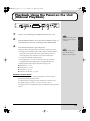
Important Notes
291a
360
In addition to the items listed under “USING THE UNIT
SAFELY” on page 3, please read and observe the
following:
• Depending on the material and temperature of the surface
on which you place the unit, its rubber feet may discolor
or mar the surface.
You can place a piece of felt or cloth under the rubber feet
to prevent this from happening. If you do so, please make
sure that the unit will not slip or move accidentally.
Power Supply
301
• Do not connect this unit to same electrical outlet that is
being used by an electrical appliance that is controlled by
an inverter (such as a refrigerator, washing machine,
microwave oven, or air conditioner), or that contains a
motor. Depending on the way in which the electrical
appliance is used, power supply noise may cause this unit
to malfunction or may produce audible noise. If it is not
practical to use a separate electrical outlet, connect a
power supply noise filter between this unit and the
electrical outlet.
307
• Before connecting this unit to other devices, turn off the
power to all units. This will help prevent malfunctions
and/or damage to speakers or other devices.
308
• Although the LCD and LEDs are switched off when the
POWER switch is switched off, this does not mean that the
unit has been completely disconnected from the source of
power. If you need to turn off the power completely, first
turn off the POWER switch, then unplug the power cord
from the power outlet. For this reason, the outlet into
which you choose to connect the power cord’s plug
should be one that is within easy reach and readily accessible.
Placement
351
• Using the unit near power amplifiers (or other equipment
containing large power transformers) may induce hum.
To alleviate the problem, change the orientation of this
unit; or move it farther away from the source of interference.
352a
• This device may interfere with radio and television
reception. Do not use this device in the vicinity of such
receivers.
352b
• Noise may be produced if wireless communications
devices, such as cell phones, are operated in the vicinity of
this unit. Such noise could occur when receiving or initiating a call, or while conversing. Should you experience
such problems, you should relocate such wireless devices
so they are at a greater distance from this unit, or switch
them off.
355b
• When moved from one location to another where the
temperature and/or humidity is very different, water
droplets (condensation) may form inside the unit. Damage
or malfunction may result if you attempt to use the unit in
this condition. Therefore, before using the unit, you must
allow it to stand for several hours, until the condensation
has completely evaporated.
Maintenance
401a
• For everyday cleaning wipe the unit with a soft, dry cloth
or one that has been slightly dampened with water. To
remove stubborn dirt, use a cloth impregnated with a
mild, non-abrasive detergent. Afterwards, be sure to wipe
the unit thoroughly with a soft, dry cloth.
402
• Never use benzine, thinners, alcohol or solvents of any
kind, to avoid the possibility of discoloration and/or
deformation.
Additional Precautions
552
• Unfortunately, it may be impossible to restore the contents
of data that was stored on a memory card once it has been
lost. Roland Corporation assumes no liability concerning
such loss of data.
553
• Use a reasonable amount of care when using the unit’s
buttons, sliders, or other controls; and when using its jacks
and connectors. Rough handling can lead to malfunctions.
554
• Never strike or apply strong pressure to the display.
556
• When connecting / disconnecting all cables, grasp the
connector itself—never pull on the cable. This way you
will avoid causing shorts, or damage to the cable’s
internal elements.
557
• A small amount of heat will radiate from the unit during
normal operation.
558a
• To avoid disturbing your neighbors, try to keep the unit’s
volume at reasonable levels. You may prefer to use
headphones, so you do not need to be concerned about
those around you (especially when it is late at night).
559a
• When you need to transport the unit, package it in the box
(including padding) that it came in, if possible. Otherwise,
you will need to use equivalent packaging materials.
562
• Use a cable from Roland to make the connection. If using
some other make of connection cable, please note the
following precautions.
• Some connection cables contain resistors. Do not use
cables that incorporate resistors for connecting to this
unit. The use of such cables can cause the sound level
to be extremely low, or impossible to hear. For information on cable specifications, contact the manufacturer of the cable.
5
AR-3000R_e2.book 6 ページ 2006年9月19日 火曜日 午前11時9分
Important Notes
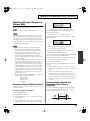
Before Using Cards
Using DATA Cards
704
• Carefully insert the DATA card all the way in—until it is
firmly in place.
fig.M512-Insert
CompactFlash™
705
• Never touch the terminals of the DATA card. Also, avoid
getting the terminals dirty.
707
• This unit’s memory card slot accepts CompactFlash
memory cards. Microdrive storage media are not
compatible.
708
• Memory cards are constructed using precision components; handle the cards carefully, paying particular note to
the following.
• To prevent damage to the cards from static electricity,
be sure to discharge any static electricity from your
own body before handling the cards.
• Do not touch or allow metal to come into contact with
the contact portion of the cards.
• Do not bend, drop, or subject cards to strong shock or
vibration.
• Do not keep cards in direct sunlight, in closed vehicles,
or other such locations (storage temperature: -25 to 85˚
C).
• Do not allow cards to become wet.
• Do not disassemble or modify the cards.
Copyright
851
• Unauthorized recording, distribution, sale, lending, public
performance, broadcasting, or the like, in whole or in part,
of a work (musical composition, video, broadcast, public
performance, or the like) whose copyright is held by a
third party is prohibited by law.
853
• Do not use this unit for purposes that could infringe on a
copyright held by a third party. We assume no responsibility whatsoever with regard to any infringements of
third-party copyrights arising through your use of this
unit.
6
AR-3000R_e2.book 7 ページ 2006年9月19日 火曜日 午前11時9分
Contents
USING THE UNIT SAFELY......................................................................3
Important Notes ......................................................................................5
Contents ..................................................................................................7
Main Features........................................................................................11
Panel Descriptions................................................................................12
Front Panel................................................................................................................................................. 12
Rear Panel .................................................................................................................................................. 14
Installing an Option Board...................................................................................................................... 15
Installation de la carte facultative (French language for Canadian Safety Standard) .................... 16
Installation .............................................................................................17
Attaching the Rubber Feet....................................................................................................................... 17
Rack Mounting (Important Notes on Heat Radiation) ....................................................................... 17
Attaching the Card Protector.................................................................................................................. 18
Examples of Usage and Connection for the AR-3000R.....................19
Together with Other Equipment (System Examples) ......................................................................... 19
Using the Control Input and Output Terminals....................................................................... 19
Using the MIDI Connectors......................................................................................................... 20
Using the RS-232C Connector ..................................................................................................... 21
Connections (Connection Methods) ...................................................................................................... 22
Dual Mono Mode .......................................................................................................................... 22
AR-LINK ........................................................................................................................................ 22
What You Can Do (Usage Tips) ............................................................................................................. 23
Repeat Playback of the Same Phrase.......................................................................................... 23
Playing a Variety of Phrases in Succession ............................................................................... 23
Turning the Power On and Off.............................................................24
Turning On the Power ............................................................................................................................. 24
Turning Off The Power............................................................................................................................ 24
Easy Setting Operations!—EZ SETUP ................................................25
What Is EZ Setup? .................................................................................................................................... 25
What You Can Do with EZ Setup .......................................................................................................... 25
Examples of EZ Setup Use ...................................................................................................................... 27
Recording Audio ........................................................................................................................... 27
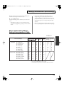
Cards Compatible with the AR-3000R.................................................30
Types of Usable Cards ............................................................................................................................. 30
Card Storage Times and Number of Phrases ....................................................................................... 30
Formatting a Card .................................................................................................................................... 31
Important Notes on Handling Cards..................................................................................................... 33
Card Compatibility with Other Models in the AR Series................................................................... 34
Using Cards Formatted on Earlier Model Units with the AR-3000R .................................... 34
Using Cards Formatted on the AR-3000R with Earlier Models ............................................. 34
The Display............................................................................................35
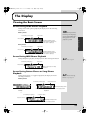
Viewing the Basic Screen......................................................................................................................... 35
Screen During Audio Phrase Playback ...................................................................................... 35
Screen During MIDI Phrase Playback........................................................................................ 35
Screen During Pattern Phrase or Song Phrase Playback......................................................... 35
Viewing the 7-segment Display .................................................................................................. 36
7
AR-3000R_e2.book 8 ページ 2006年9月19日 火曜日 午前11時9分
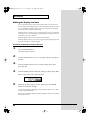
Display-related Settings........................................................................................................................... 37
Adjusting the Contrast ................................................................................................................. 37
Making the Display Go Dark ...................................................................................................... 38
Recording Audio ...................................................................................40
Recording Units—Phrases ........................................................................................................... 40
Connecting Equipment ................................................................................................................ 40
Procedure for Recording ......................................................................................................................... 41
Enabling Recording Standby....................................................................................................... 41
Required Settings for Recording Audio Signals (Recording Settings) .................................. 42
Starting and Ending Recording................................................................................................... 49
Checking What You Recorded ............................................................................................................... 50
Information Recorded on the Card ............................................................................................ 50
Important Note: About Setting Information Imported from a Card..................................... 50
Playback Using the Panel on the Unit (Manual Playback) ................51
Modifying Recorded Phrases
(Phrase Settings).............................54
Adding Information to Individual Phrases (Phrase Information) .................................................... 54
Three Useful Playback Modes for Phrase Settings................................................................... 54
Play Volume (%)............................................................................................................................ 54
Delay Time (00s 00f to 59s 29f) .................................................................................................... 55
Playback Point (Start and End) ................................................................................................... 55
Repeat Play (Repeat, Repeat Interval)....................................................................................... 57
Loop Play (Loop, Loop 1,
Loop 2, Crossfade Time) .............................................................................................................. 57
Fade (Fade In and Fade Out)....................................................................................................... 58
Control Out .................................................................................................................................... 59
Changing the Playback Tempo for MIDI Phrases (MIDI Playback Tempo) ........................ 60
Phrase Name .................................................................................................................................. 60
Creating Combinations of Phrases (Phrase Combination)................................................................. 62
Combinations of Phrase Units (Pattern Phrases)...................................................................... 62
Time-based Combinations (Song Phrases) ................................................................................ 65
Modifying Phrases Themselves (Phrase Edit)...................................................................................... 67
Deleting a Phrase (Phrase Delete)............................................................................................... 67
Deleting Audio Outside the Playback Points (Phrase Truncate) ........................................... 67
Copying a Phrase (Phrase Copy) ................................................................................................ 68
Dividing a Phrase (Phrase Divide) ............................................................................................. 69
Joining Phrases (Phrase Combine).............................................................................................. 70
Expanding or Compressing the Playback Time Without Changing the Pitch (Time Stretch)
71
Converting a Phrase’s Recording Settings (Phrase Convert) ................................................. 72
Phrase Information/Phrase Setting Correspondence Table .............................................................. 75
Making Settings and Edits for Individual Cards ................................76
Making a Card Usable on the AR-3000R (Card Format)......................................................... 76
Deleting All Phrases on a Card (Card Delete) .......................................................................... 76
Copying a Card (Card Copy) ...................................................................................................... 76
Copying Just the Settings (Setting Copy) .................................................................................. 77
Protecting a Card (Card Protect)................................................................................................. 77
Changing the Name of a Card (Card Name) ............................................................................ 77
Making Cards for Legacy Models Usable on the AR-3000R (Card Convert)....................... 78
Card Conversion Chart/Conversion Error Chart .................................................................... 80
Recording and Playing MIDI Data (MIDI Phrases)..............................82
What Are MIDI Phrases? ............................................................................................................. 82
Connecting Equipment ................................................................................................................ 82
Unit Settings................................................................................................................................... 82
Starting and Ending Recording................................................................................................... 83
Playback of MIDI Phrases............................................................................................................ 84
Playback Procedures..................................................................................................................... 84
8
AR-3000R_e2.book 9 ページ 2006年9月19日 火曜日 午前11時9分
Controlling the AR-3000R from an External Device (Control Input
Terminals)..............................................................................................85
What Is No-voltage/Make-contact? ........................................................................................... 85
Types of Control Input Playback ................................................................................................ 85
Type of Control Input Recording ............................................................................................... 86
Assigning a Phrase to a Port and Playing It Back (Direct Playback) ................................................ 86
What Is Direct Playback?/Uses and Applications ................................................................... 86
Connecting External Equipment................................................................................................. 86
Operational Specifications for Direct Playback ........................................................................ 86
AR-3000R Settings......................................................................................................................... 87
Playing Back Phrases in the Order They Are Selected (Program Playback) ................................... 89
What is Program Playback?/Uses and Applications............................................................... 89
Connecting External Equipment................................................................................................. 90
Operational Specifications for Program Playback.................................................................... 90
Display Indications During Program Playback........................................................................ 91
AR-3000R Settings......................................................................................................................... 91
Specifying Phrase Numbers in Binary Notation (Binary Playback) ................................................. 92
What is Binary Playback?/Uses and Applications .................................................................. 92
Connecting External Equipment................................................................................................. 93
Operational Specifications of Binary Playback......................................................................... 93
AR-3000R Settings......................................................................................................................... 94
To Specify Phrases With Binary Signals .................................................................................... 95
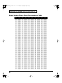
Phrase Number/Binary Signal Correspondence Table........................................................... 96
.......................................................................................................................................................... 97
Controlling Recording with the Control Terminals (Binary Recording) ......................................... 98
What is Binary Recording/Uses and Applications.................................................................. 98
Connecting Equipment ................................................................................................................ 98
Operational Specifications for Binary Recording ..................................................................... 98
AR-3000R Settings....................................................................................................................... 100
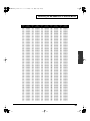
To Specify Phrases With Binary Signals .................................................................................. 101
Controlling Another Device with the AR-3000R (Control Output
Terminal)..............................................................................................102
Starting Another Device (Busy Out).................................................................................................... 102
What Is a Busy Out Signal?/Equipment Connections .......................................................... 102
AR-3000R Settings....................................................................................................................... 103
Controlling Another Device (Control Out)......................................................................................... 104
What Is a Control Out Signal?/Equipment Connections...................................................... 104
AR-3000R Settings....................................................................................................................... 104
Controlling the AR-3000R Using MIDI Signals (MIDI Control) ........105
What Is MIDI Control?/What You Can Do with MIDI Control .......................................... 105
Glossary of Selected MIDI Terms ............................................................................................. 105
Playback of Phrases Using MIDI Signals ............................................................................................ 105
Connecting External Equipment............................................................................................... 106
AR-3000R Settings....................................................................................................................... 106
Operation Procedures................................................................................................................. 109
Synchronizing Operation to an External MIDI Instrument – 1 (MMC) ......................................... 110
What Is MMC?/Remote Control from Another Device........................................................ 110
Connecting External Equipment............................................................................................... 110
AR-3000R Settings....................................................................................................................... 110
Operation Procedures................................................................................................................. 112
Synchronizing Operation to an External MIDI Instrument – 2 (MMC and MTC) ....................... 112
What Is MTC?/Synchronized Playback with Video Equipment and Other Devices ....... 112
Connecting External Equipment............................................................................................... 113
AR-3000R Settings (When the AR-3000R Is the Slave) .......................................................... 113
Operation Procedures................................................................................................................. 116
AR-3000R Settings (When the AR-3000R Is the Master) ....................................................... 116
Operation Procedures................................................................................................................. 117
MTC Offset Setting ..................................................................................................................... 118
9
AR-3000R_e2.book 10 ページ 2006年9月19日 火曜日 午前11時9分
Controlling the AR Using the RS-232C Connector ..........................119
What’s the RS-232C Connector?/What You Can Do with the RS-232C Connector.......... 119
Connecting Equipment .............................................................................................................. 119
Baud Rate Setting ........................................................................................................................ 119
Available Documentation for the RS-232C.............................................................................. 119
Playing Two Units’s Worth of Data on the Left and Right (Dual Mono
Mode) ...................................................................................................120
What Is the Dual Mono Mode?/Equipment Connections .................................................... 120
AR-3000R Settings....................................................................................................................... 120
Operation Procedures................................................................................................................. 121
Synchronized Recording and Playback with Multiple AR Units (ARLINK) ....................................................................................................123
What Is AR-LINK?/What You Can Do Using AR-LINK...................................................... 123
Synchronized Audio Phrase Playback with AR-LINK Signals ....................................................... 123
Example of Connecting to an External Device ....................................................................... 123
Unit Settings................................................................................................................................. 124
Recording Procedure .................................................................................................................. 124
Playback Procedure .................................................................................................................... 124
Other Useful Functions During Phrase Playback ............................125
Line Out (Thru) Setting During Phrase Playback.............................................................................. 125
Handy Uses of Line Thru........................................................................................................... 125
Line Thru Settings ....................................................................................................................... 125
Adjusting the Sound Quality During Audio Phrase Playback (Equalizer) ................................... 126
Keeping the Output Volume Unchanged (Output Volume Thru).................................................. 127
Troubleshooting..................................................................................129
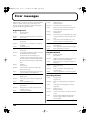
Error messages...................................................................................132
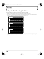
Cards....................................................................................................134
Card-specific Audio Recording Time Chart....................................................................................... 134
Settings When a Card Is Formatted ..................................................................................................... 135
Recorded Phrase Data............................................................................................................................ 136
Terminals .............................................................................................137
Specifications of the Control Input/Output Terminals .................................................................... 137
RS-232C Connector Specifications ....................................................................................................... 137
AR-LINK Connectors Specifications ................................................................................................... 138
MIDI Implementation...........................................................................139
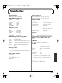
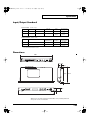
Specification........................................................................................147
Input/Output Standard......................................................................................................................... 149
Dimentions .............................................................................................................................................. 149
Index.....................................................................................................150
10
AR-3000R_e2.book 11 ページ 2006年9月19日 火曜日 午前11時9分
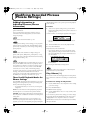
Main Features
High-quality Recording and Playback
Thanks to Roland’s innovative RDAC system, you can enjoy
high-quality, 24-bit recording and playback at 48 kHz using
less data. You can select recording settings that suit the
situation and the capacity of the card (sampling frequency: 6
levels, recording mode: 5 levels). This ensures support for
recording and playback in a variety of situations and uses.
What you record and the settings are all saved on the card, so
you can change situations rapidly simply by changing cards.
You can record and play back up to 2,000 phrases (when
using two cards).
Audio Recording System with No
Moving Parts
An audio recording system that uses CF cardsnd has no
moving parts is employed. The system has no rotating parts
or drive mechanism, so it’s practically maintenance free. This
makes for outstanding durability with no loss of sound
quality.
Two-unit Playback with a Single Unit–
Dual Mono Mode
The Dual Mono mode lets you manipulate the left and right
channels independently, and play back mono audio phrases
individually. This means you can play back material for two
units on a single AR-3000R. You can also play back separate
phrases on the left and right channels either simultaneously,
or shifted.
Built-in 2-band Equalizer
The unit features an internal 2-band equalizer for audiophrase effects. This enables on-site correction of the sonic
field.
A Variety of Control Jacks for a Wide
Range of Playback Methods
Digital In Jack
As connectors to use for control, the unit features a Control
In jack, MIDI connectors, an RS-232C port, and AR-LINK
connectors. This lets you select from a variety of playback
methods and create systems matched to usage and
situations.
In addition to a Line In jack (analog) and Mic jack, the unit
also features a Digital In jack. This means you can record
audio phrases of even higher sound quality by connecting
the unit to a digital-output device.
MIDI Connectors Allow for Play of
Musical Instruments and Syncing with
Video
Large screen, Easy-to-understand
Messages, and EZ Setup Feature
Assure Simple Settings and Operation
Since the unit is equipped with MIDI connectors, you can
record and play back MIDI signals. You can play an
electronic musical instrument automatically, just like playing
back an audio phrase.
The large display and easy-to-understand messages make it
simple to make settings.
The unit also has a built-in EZ Setup feature that lets you
make settings interactively.
Control of recording/playback using MIDI signals is also
supported. This means you can use MTC and MMC signals
to obtain recording/playback that is synchronized to video
and other external devices.
You’ll appreciate the impressive power this provides when
you’re using the AR-3000R for the first time, or when you
need to change the settings in a hurry during play.
Multi-track Operation–AR-LINK
Feature
A Full Array of Editing Features for
Modifying Phrases the Way You Want
You can use the AR-3000R like a sampler to edit and modify
recorded material, including dividing, joining, and stretching
the time. Nondestructive editing is possible, so you can
modify the material without worrying about loss.
The AR-LINK feature lets you link the unit to up to 32 other
units to create a completely synchronized multi-track system.
Conversion Feature for Using Data
from Legacy Models
Performing conversion with the Card Conversion feature
makes it possible for the AR-3000R to utilize cards used with
the earlier AR-2000/100 models, or to use cards created with
the AR-3000R on earlier models. This bidirectional data
exchange lets you make effective use of materials and data.
11
AR-3000R_e2.book 12 ページ 2006年9月19日 火曜日 午前11時9分
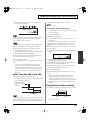
Panel Descriptions
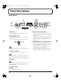
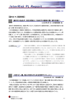
Front Panel
fig.2-01e
9
5
1 2
3
7
4
6
8
10 12 13 14
16
15
11
17
1. Mic In Jack
7. PLAY Button and PLAY Indicator
This is for connecting a microphone during audio recording.
→ “Recording Audio” (p. 40)
2. INPUT VOLUME Knobs
The outer control adjusts the volume level of the signal input to
the Line In jack.
The inner control adjusts the microphone-input volume level.
fig.2-02e
MIC Volume
(inner ring)
LINE Volume
(outer ring)
→“Recording Audio” (p. 40)
The volume level of signals input to the Digital In jack cannot
be changed.
• Pressing the PLAY button plays back a phrase. When
playback is paused, pressing the PLAY or PAUSE button
restarts playback.
• Holding down the STOP button and pressing the PLAY
button puts the unit in recording standby. Pressing the
PLAY or PAUSE button while in this state starts
recording.
8. PAUSE/BACK Button and PAUSE Indicator
• Pressing the PAUSE button during playback of an audio
phrase pauses playback. Playback resumes when the
PLAY or PAUSE button is pressed again.
• Pressing the PLAY or PAUSE button while in the
recording-standby state starts recording.
• When you are making settings, this button is used to
make the insertion point (highlighted) go back one step.
3. Card Access Indicator
This lights up when the unit reads or writes to a card.
When the CF card drive is in operation (that is, when the
access indicator is illuminated), do not try to take out the
card or turn off the power. Doing so may damage the card.
4. Card Slots
Do not insert any object other than a CF card (such as a wire,
coin, or different type of card) into the card slots. Doing so
may damage the unit.
5. Card Eject Buttons
6. Display
→“Viewing the Basic Screen” (p. 35)
962a
12
* In the interest of product improvement, the specifications and/or appearance of this unit are subject to change without prior notice.
AR-3000R_e2.book 13 ページ 2006年9月19日 火曜日 午前11時9分
Panel Descriptions
12. ENTER Button
fig.2-03e
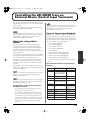
●About When the Indicators Light/Flash
When Playing Back/Recording
State
PLAY button
indicator
PAUSE button
indicator
During Playback
Lights in green
Extinguished
During Pause
(Playback)
Flashes in green
Flashes in green
During Recording
Flashes in red
Standby
Flashes in red
During Recording Lights in red
Extinguished
→"Recording Audio" (p. 40)
→"Playback Using the Panel on the Unit
(Manual Playback)" (p. 51)
13. SELECT Dial (Doubles As SELECT Button)
This is used for such operations as selecting phrases and
choosing setting items.
14. OUTPUT VOLUME Knob
This adjusts the volume level of the final output (at the audio
output jacks).
To prevent incorrect operation, you can disable this control
and set the volume at a fixed level.
→ “Keeping the Output Volume Unchanged (Output Volume
Thru)” (p. 127)
15. Headphones Jack
When Sync Source is set to MTC
State
During Pause
(Playback)
PLAY button
indicator
Lights in green
During Recording
Lights in red
Standby
PAUSE button
indicator
Lights in orange
Lights in orange
→"Controlling the AR-3000R Using MIDI Signals
(MIDI Control)" (p. 105)
9. STOP Button
• Pressing the STOP button stops phrase playback or
recording, extinguishing the PLAY indicator.
• Holding down the STOP button and pressing the PLAY
button puts the unit in recording standby.
10. EZ SETUP Button and EZ SETUP Indicator
This activates the EZ Setup feature, which lets you make settings
interactively.
This is for connecting headphones for monitoring recording and
playback.
The headphones volume level is adjusted with the OUTPUT
VOLUME control (the same as for the final volume [the audio
output jacks]).
When you activate the Volume Thru feature, you can use the
OUTPUT VOLUME control to adjust the headphones volume
even when the OUTPUT VOLUME control has been deactivated.
16. POWER Switch
Turn the AR-3000R’s power on and off.
* If you need to turn off the power completely, first turn off the
POWER switch, then unplug the power cord from the power
outlet. Refer to Power Supply (p. 5).
17. Card Protector (Included)
This allows you to prevent the card being removed by mistake.
Use this feature if you’re using the AR-3000R for the first time, or
when you need to change the settings in a hurry during play.
The indicator lights up when EZ Setup is active.
→ “Easy Setup and Operation!–EZ Setup” (p. 25)
11. MODE Button and MODE Indicator
For entering the mode for making settings. The indicator lights
up while settings are made.
13
AR-3000R_e2.book 14 ページ 2006年9月19日 火曜日 午前11時9分
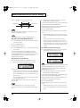
Panel Descriptions
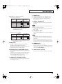
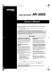
Rear Panel
fig.2-04e
1
2
4
3
12
5 6
9
7
8
9
Top Panel
1. AC Inlet
This is for connecting the included AC power cord. Connect it
securely so that it doesn’t come loose.
(Refer to p. 147 – for power requirements)
*The unit should be connected to a power source
only of the type maked on the side of unit.
2. AR-LINK Connectors (OUT and IN)
These are for connecting the AR units to each other when you’re
using more than one AR unit at the same time.
→ “Synchronized Recording and Playback with Multiple AR
Units (AR-LINK)” (p. 123)
3. MIDI Connectors (OUT/THRU and IN)
These are used to make the connections when you operate the
AR with MIDI signals for recording MIDI phrases, performing
MIDI control, and so on.
• MIDI IN: This receives MIDI information from another MIDI
instrument.
• MIDI OUT: This sends MIDI information from the AR-3000R.
• MIDI THRU: This sends, unchanged, MIDI information
received by MIDI IN.
On the AR-3000R, a single connector doubles in use for MIDI
OUT and MIDI THRU. When shipped from the factory, the
connector is set to “OUT.” You can change the function of the
connector as required.
→ “Recording and Playing MIDI Data” (p. 82)
→“Controlling the AR with MIDI Signals (MIDI control)” (p.
105)
4. DIGITAL IN Jack (Coaxial, S/P DIF, EIAJ CP1201-compliant)
This is used when recording audio from a device equipped with
a digital audio-output jack.
14
11
927
5. Ground Terminal
Depending on the circumstances of a particular setup, you may
experience a discomforting sensation, or perceive that the
surface feels gritty to the touch when you touch this device,
microphones connected to it, or the metal portions of other
objects. This is due to an infinitesimal electrical charge, which is
absolutely harmless. However, if you are concerned about this,
connect the ground terminal (see figure) with an external
ground. When the unit is grounded, a slight hum may occur,
depending on the particulars of your installation. If you are
unsure of the connection method, contact the nearest Roland
Service Center, or an authorized Roland distributor, as listed on
the “Information” page.
Unsuitable places for connection
• Water pipes (may result in shock or electrocution)
• Gas pipes (may result in fire or explosion)
• Telephone-line ground or lightning rod (may be dangerous in
the event of lightning)
6. RS-232C Connector
This is used when connecting the AR-3000R to a computer or the
like for exchanging signals.
→“Controlling the AR Using the RS-232C Connector” (p. 119)
7. Control Input/Output Terminals
These are used for connecting to external control devices.
• Controlling the AR-3000R with Signals from an External
Control Device
→“Controlling the AR-3000R from an External Device (Control
Input Terminals)” (p. 85)
• Controlling an External Device with Signals from the
AR-3000R
→ “Controlling Another Device with the AR-3000R(Control
Output Terminals)” (p. 102)
* In the interest of product improvement, the specifications and/or appearance of this unit are subject to change without prior notice.
AR-3000R_e2.book 15 ページ 2006年9月19日 火曜日 午前11時9分
Panel Descriptions
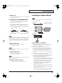
Installing an Option Board
8. LINE IN Jack
This is used when recording audio from a device equipped with
an analog audio-output jack.
9. Audio Output Jacks (BALANCED OUTPUT)
When installing, be sure refer to the owner’s manual for the
respective option board.
These are the final audio output jacks. They are used for
connection to a power amp or the like. Both balanced and
unbalanced connections are possible.
fig.2-06e
Top Panel
922
Removed screws
* This instrument is equipped with balanced (TRS) type jacks.
Wiring diagrams for these jacks are shown below. Make
connections after first checking the wiring diagrams of other
equipment you intend to connect.
fig.2-05e
GND(SLEEVE)
HOT(TIP)
GND(SLEEVE)
HOT(TIP)
Option board
COLD(RING)
Balanced Output
Unbalanced Output
Rear Panel
926a
When connection cables with resistors are used, the volume
level of equipment connected to the inputs (LINE IN Jack)
may be low. If this happens, use connection cables that do
not contain resistors, such as those from the Roland PCS
series.
Important Notes on Installation
10. Option Board Slot
● Before installing the board, switch off the power to the
equipment and unplug the power cord from the power outlet.
This is the recess for installing an option board.
→ “Installing an Option board”
● Remove only the specified screws.
● Be careful not to let removed screws fall into the unit.
When installing, be sure to refer to the owner’s manual for
the option board.
● After you have removed the panel, cover, and screws, do not
leave them off. When you have finished installing the option
board, be sure to reattach the panel, cover, and screws.
11. Option Board Space
● Be careful not to cut your hand on the opening for installing the
board.
● After installation, if the unit fails to power up when you switch
on the power, contact your Roland Service Station.
This is where an option board is installed.
→ “Installing an Option board”
901
When installing, be sure to refer to the owner’s manual for
the respective option board.
12. Rubber Feet (Included Items)
→ “Attaching the Rubber Feet (Included Items)” (p. 17)
● To avoid the risk of damage to internal components that can be
caused by static electricity, please carefully observe the
following whenever you handle the board.
• Before you handle the circuit board, first touch the front panel
of the AR-3000R, and while maintaining contact with the front
panel, pick up the circuit board. This discharges any static
electricity that has accumulated in your body and clothing.
• When handling the board, grasp it only by the panel or the
board’s edges. Avoid touching any of the electronic
components or connectors.
• When handling the board, grasp it only by the panel or
the board’s edges. Avoid touching any of the electronic
components or connectors.
• Before you connect any cables, make sure they do not
carry a static electricity charge. Such charges can be
15
AR-3000R_e2.book 16 ページ 2006年9月19日 火曜日 午前11時9分
Panel Descriptions
transmitted, for example, if the other end of the cable
has been in contact with a carpet (or other object) where
there is a static electricity buildup.
•Save the bag in which the board was originally shipped, and
put the board back into it whenever you need to store or
transport it.
911 ●
912
Always turn the unit off and unplug the power cord before
attempting installation of the circuit board (model no. AR-NT1/
AR-NT1R).
915 ●
Install only the specified circuit board(s) (model no. AR-NT1/
AR-NT1R). Remove only the specified screws.
928
Do not touch any of the printed circuit pathways or connection
terminals.
● Never use excessive force when installing a circuit board. If it
doesn’t fit properly on the first attempt, remove the board and
try again.
913 ●
914 ●
● When turning the unit upside-down, get a bunch of newspapers
or magazines, and place them under the four corners or at both
ends to prevent damage to the buttons and controls. Also, you
should try to orient the unit so no buttons or controls get
damaged.
929 ●
When circuit board installation is complete, double-check your
work.
Installation de la carte facultative
When turning the unit upside-down, handle with care to avoid
dropping it, or allowing it to fall or tip over.
(French language for Canadian Safety
Standard)
● Après l’installation, si l’unité ne se remet pas en marche lorsque
vous la rallumez, communiquez avec le centre de service
Roland.
Pour de plus amples renseignements sur la procédure
d’installation, reportez-vous à la documentation spécifique à la
carte facultative.
fig.install_F
Top Panel
Vis retirées
901(F) ●
Veuillez suivre attentivement les instructions suivantes quand
vous manipulez la carte afin d’éviter tout risque
d’endommagement des pièces internes par l’électricité statique.
• Toujours toucher un objet métallique relié à la terre (comme un
tuyau par exemple) avant de manipuler la carte pour vous
décharger de l’électricité statique que vous auriez pu
accumuler.
• Lorsque vous manipulez la carte, la tenir par les côtés. Évitez
de toucher aux composants ou aux connecteurs.
• Lorsque vous manipulez la carte, la tenir par les côtés de la
plaque ou par les côtés du circuit imprimé. Évitez de toucher
aux composants ou aux connecteurs.
Option board
Rear Panel
• Avant de connecter tout câble, assurez-vous qu’il ne contient
aucune charge d’électricité statique. De telles charges peuvent
être transmises, par exemple, si l’autre extrémité du câble
touche à un tapis (ou autre objet) où il y a accumulation
d’électricité statique.
• Conservez le sachet d’origine dans lequel était la carte lors de
l’envoi et remettez la carte dedans si vous devez la ranger ou la
transporter.
Remarques importantes sur
l’installation
911(F)
● Ne pas toucher aux circuits imprimes ou aux connecteurs.
912(F)
● Ne jamais forcer lors de l’installation de la carte de circuits
imprimes. Si la carte s’ajuste mal au premier essai, enlevez la
carte et recommencez l’installation.
● Avant d’installer la carte, éteignez l’équipement et débranchez le
cordon d’alimentation de la prise.
913(F) ● Quand l’installation de la carte de circuits imprimes est
terminee, reverifiez si tout est bien installe.
● Retirez uniquement les vis indiquées.
914(F) ● Toujours eteindre et debrancher l’appareil avant de commencer
● Faites attention de ne pas laisser les vis tomber dans l’unité.
l’installation de la carte. (modele no AR-NT1/AR-NT1R).
● Après avoir retiré le panneau, le couvercle et les vis, ne les
915(F)
laissez pas ainsi. Une fois terminée l’installation de la carte
facultative, assurez-vous de remettre le panneau, le couvercle et
les vis en place.
● Faites attention de ne pas vous couper sur l’ouverture
d’installation de la carte.
16
● N’installez que les cartes de circuits imprimes specifiees (modele
no AR-NT1/AR-NT1R). Enlevez seulement les vis indiquees.
AR-3000R_e2.book 17 ページ 2006年9月19日 火曜日 午前11時9分
Installation
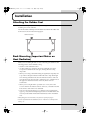
Attaching the Rubber Feet
Attach these as required, such as when you’re using the AR-3000R without
mounting it on a rack or the like.
Peel off the double-sided tape from the rubber feet and affix the rubber feet
at the locations shown in the following figure.
fig.4-01e
Bottom chassis
Rack Mounting (Important Notes on
Heat Radiation)
When you are mounting the unit on a rack or the like, give attention to the
following points to ensure efficient cooling.
• Install in a well-ventilated location.
• Avoid mounting in a sealed rack. Warm air within the rack cannot
escape and is sucked into the unit again, making efficient cooling
impossible.
• When you are using a stacked mounting arrangement, be especially sure
to provide for adequate ventilation within the rack to keep discharged
air from being sucked back into the unit. If the back surface of the rack
cannot be kept open, then provide a ventilation port or ventilation fan at
the upper area of the back surface of the rack, where warm air
accumulates.
• When you are using the unit in a portable case or rack, remove the
covers from the front and back surfaces of the case, so that the front and
back surfaces of the unit are not obstructed.
• If an error message informing you of a dangerous rise in temperature
appears (p. 132), then heat-dissipating measures are needed. Refer to the
cautions just described and check the installed state of the unit and the
rack.
* When placing the unit on the rack, be careful not to pinch your fingers.
* For more information about installation, also see “Placement” in the Important
Notes (p. 5).
17
AR-3000R_e2.book 18 ページ 2006年9月19日 火曜日 午前11時9分
Installation
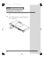
Attaching the Card Protector
By attaching the Card Protector (supplied) to the AR-3000R, you can
prevent the memory card from inadvertently being removed from the AR3000R.
1
After confirming that the card is securely inserted in the card
slot, use the provided screws to attach the Card Protector, as
shown in the figure below.
fig.CardProtect.e
Card Protector
18
AR-3000R_e2.book 19 ページ 2006年9月19日 火曜日 午前11時9分
Examples of Usage and Connection
for the AR-3000R
You can use the AR-3000R alone or in combination with other AR-3000R
units or other equipment to play audio in a wide variety of scenes. This
section shows some examples of these. You can use these examples as a
starting point for making changes to match your own usage circumstances.
Together with Other Equipment (System
Examples)
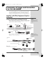
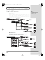
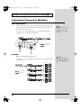
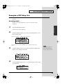
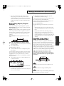
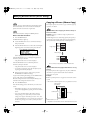
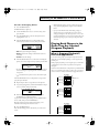
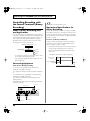
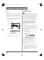
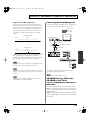
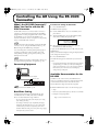
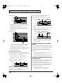
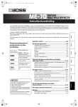
Using the Control Input and Output Terminals
● Control Input: Messages, explanations, warnings, announcements, effect
sounds, and the like are played with high sound quality according to control
signals from sensors, buttons, and switches.
Controlling the AR-3000R
from an External Device
(Control Input Terminals)
→ p. 85
fig.5-01e
Sensor
Program Timer
Momentary Switch
pm.
Pressing the switch plays back
a set announcement, guidance
message, explanation, or the like
•Set announcements played back as required
•Broadcast of museum exhibition explanations
or guidance
Sensor-triggered automatic
broadcasts
Control timer for automatic
broadcasts
•Guidance announcements made upon
detection of a person’s presence
•Playback of event performances at
attractions and other sites
•Playback of message broadcasts and
announcements at regular, set times in
offices, factories, or other such areas
•Broadcasts at set times of upcoming
events at amusements areas
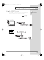
Types of External Control
Power Amp
Control Signal
Audio Signal
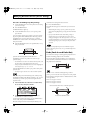
● Control Output: Control signals can be output during or after phrase
playback to control an external device.
Controlling Another
Device with the AR-3000R
(Control Output Terminals)
→ p. 102
fig.5-02e
Busy Out
Control Signal
Audio Signal
Power Amp
Only during phrase playback, power amp or other
gear is powered up (delay time set to five seconds)
Lamp lights during phrase playback
Power Unit
Power
Reray
Switch
Control Out
After playback ends, controls external device
Power Amp
•Extinguishing lights
•When elevator doors are closed and
other similar situations
19
AR-3000R_e2.book 20 ページ 2006年9月19日 火曜日 午前11時9分
Examples of Usage and Connection for the AR-3000R
Using the MIDI Connectors
Controlling the AR-3000R
Using MIDI Signals (MIDI
Control) → p. 105
● Spatial Expression
With the AR-3000R serving as the master, the MIDI signals it sends out can
be used to get a sound module to play background music. Or, you can have
sound-effect phrases be played by a slaved AR-3000R. This lets you create
sonic fields with six-channel multi-playback.
fig.5-03e
(for MIDI Sequencer)
MIDI patch bay
MIDI signal
Audio signal
Sound Module
Power Amp.
Power Amp.
Power Amp.
● Sound-field Control
Using batch MIDI control from a switch box, you can change programs on a
mixer, equalizer, or the like to control the sonic field.
fig.5-04e
Switch box
(for MIDI Sequencer)
Digital Mixer
& Console
Control signal
MIDI signal
Audio signal
MIDI patch bay
Equalizer
Power Amp.
Equalizer
Power Amp.
20
AR-3000R_e2.book 21 ページ 2006年9月19日 火曜日 午前11時9分
Examples of Usage and Connection for the AR-3000R
Using the RS-232C Connector
By connecting an RS-232C cable, you can control the AR-3000R from an
external control device, such as a computer or touch panel.
Controlling the AR Using
the RS-232C Connector →
p. 119
fig.5-05e
Control signal
Audio signal
●AR Control with a computer
Power Amp.
●Explanatory messages and guidance for public facilities and museum exhibits
CONTROL PANEL
Control Interface
Power Amp.
21
AR-3000R_e2.book 22 ページ 2006年9月19日 火曜日 午前11時9分
Examples of Usage and Connection for the AR-3000R
Connections (Connection Methods)
Dual Mono Mode
The Dual Mono mode is a feature for playing different mono audio phrases
independently on the left and right channels. This lets you use the unit to
play two units’s worth of data.
You can also play back separate phrases on the left and right channels
simultaneously, or control them individually.
Playing Two Unit’s Worth
of Data on the Left and
Right (Dual Mono Mode)
→ p. 120
fig.5-06e
Power Amp.
E x h ib it A
E x h ib it B
Control signal
Audio signal
AR-LINK
● Connecting with the AR-LINK Cable
You can operate four AR-3000R units completely in sync as an eight-channel
multi-player.
fig.5-07e
Power Amp.
Control input
Control signal
Audio signal
22
Synchronized Recording
and Playback with Multiple
AR Units (AR-LINK) → p.
123
AR-3000R_e2.book 23 ページ 2006年9月19日 火曜日 午前11時9分
Examples of Usage and Connection for the AR-3000R
What You Can Do (Usage Tips)
Repeat Playback of the Same Phrase
There are several methods for doing this. Choose a playback method that
matches your usage conditions.
Setting the Phrase Information for Repeat Play
You can repeat each individual phrase.
Repeat Play → p. 57
You can also do repeat play for a phrase combination (a group of phrases).
Phrase Combinations → p.
62
Inputting a Continuous Make-contact Signal to the Control Input
Terminals
You can repeat playback by continuously shorting the control input
terminals.
* With some settings, playback doesn’t repeat even when you continuously input a
make-contact signal.
For information, refer to “Controlling the AR-3000R from an External
Device (Control Input Terminals)” (p. 85).
Playing a Variety of Phrases in Succession
There are several methods for doing this. Choose a playback method that
matches your usage conditions.
Using Phrase Combinations
This continuously plays back stored phrases in succession.
Phrase Combinations → p.
62
Using Direct Playback of Control Input
By inputting control signals to a port number from 1 through 16, you can
play back the phrase assigned to the number.
Direct Playback → p. 86
Using Program Playback of Control Input
This successively plays back phrases in preset sequence each time a control
signal is input to the START port.
Program Playback → p. 89
Using Binary Playback of Control Input
You can select phrases by inputting binary signals to port numbers 1
through 10, and play the selected phrases in succession each time you input
control signals to the START port.
Binary Playback→ p. 92
23
AR-3000R_e2.book 24 ページ 2006年9月19日 火曜日 午前11時9分
Turning the Power On and Off
Turning On the Power
941
* Once the connections have been completed (p. 40), turn on power to your various
devices in the order specified. By turning on devices in the wrong order, you risk
causing malfunction and/or damage to speakers and other devices.
Power on your equipment as described in the following. After the devices
are powered on, set the volumes to each connected devices equipment.
Connected devices → AR-3000R → Power Amplifier etc.
942
1
2
3
Confirm the volume levels on the AR-3000R and any amp or
mixer that is connected turned down to the lowest settings.
This unit is equipped with
a protection circuit. A brief
interval (a few seconds)
after power up is required
before the unit will operate
normally.
Press the POWER switch to turn on the power.
To avoid risk of electric
shock, do not touch the
connectors while the unit is
in operation.
Watch the display.
* This display is only an example for illustrative purposes, The content of the display
will differ depending on the card settings.
Turning Off The Power
945
1
2
Confirm the volume levels on the AR-3000R and any amp or
mixer that is connected turned down to the lowest settings.
Switch off the power of the device in the reverse order of that
used to switch on the power.
The display will go dark, indicating that the power has been turned off.
24
If you need to turn off the
power completely, first
turn off the POWER switch,
then unplug the power
cord from the power outlet.
Refer to Power Supply (p.
5)
AR-3000R_e2.book 25 ページ 2006年9月19日 火曜日 午前11時9分
Easy Setting Operations!—EZ SETUP
What Is EZ Setup?
On the AR-3000R, settings are normally made by using the MODE button to
enter the setting mode, then selecting the needed items from the various
menu levels.
EZ Setup is an interactive method for making settings, whereby you first
select the target and the feature you want to use, then make the necessary
settings, one after another.
Basic Operations
Use this feature if you’re using the AR-3000R for the first time, if you don’t
know what items need to be set, or when you need to change the settings in
a hurry during play.
What You Can Do with EZ Setup
With EZ Setup, you can make target-specific and function-specific settings
like the ones shown below.
A. Creating Cards
1. Creating a New Card (p. 31)
2. Copying a Card (p. 76)
3. Using AR-2000 Cards (p. 78)
B. Recording Phrases
1. Audio Recording (Line Input) (p. 40)
2. Audio Recording (Line + Mic) (p. 40)
3. Audio Recording (Digital Connectors) (p. 40)
4. MIDI Recording (p. 82)
C. Phrase Editing
1. Phrase Information Settings (p. 54)
• Playback Volume Setting
• Loop Play
• Repeat Play
2. Combining Phrase (p. 62)
• Creating Pattern Phrases
• Creating Song Phrases
3. Modifying Phrases (p. 67)
• Deleting Phrases
• Splitting Phrases
25
AR-3000R_e2.book 26 ページ 2006年9月19日 火曜日 午前11時9分
Easy Setting Operations!—EZ SETUP
• Joining Phrases
• Expanding and Compressing Playback Times (Time Stretch)
• Copying Phrases
D. Control from an External Device
1. Playback Using the Screw-on Connectors (p. 85)
• Selected Playback of Stored Phrases
• Sequential Playback of Stored Phrases
• Playback of Specified Phrase Numbers
• Recording Specified Phrase Numbers
2. Playback Using MIDI Signals (p. 105)
3. Control Using RS-232C (p. 119)
E. Independent playback of L and R channels (p. 120)
F. Synchronizing Multiple Devices
1. Synchronization Using AR-LINK (p. 123)
2. Synchronization Using MIDI (p. 110)
G. LCD Settings
1. Adjusting LCD Contrast (p. 37)
2. LCD Auto Power-off (p. 38)
H. Control Output Signal Settings
1. Signal Settings for Starting Other Equipment (p. 102)
2. Signal Settings for Controlling Other Equipment (p. 104)
I. Line Output Settings
1. Line Thru Settings During Playback (p. 125)
2. Adjusting the Sound Quality of Audio Phrases (p. 126)
3. Locking Output Volume (p. 127)
26
AR-3000R_e2.book 27 ページ 2006年9月19日 火曜日 午前11時9分
Easy Setting Operations!—EZ SETUP
Examples of EZ Setup Use
This section describes “recording audio” as an example of operations using
EZ Setup.
Recording Audio
Refer to “Connecting Equipment” (p. 40) and connect the external
equipment.
Press the EZ SETUP button.
Basic Operations
1
The EZ SETUP indicator lights up.
2
Turn the SELECT dial to choose the “Recording Phrases” icon,
then press the dial.
fig.EZ-01
Present icon location
Number of icons on the menu
The present screen content and messages are scrolled at the bottom of the
screen.
3
Turn the SELECT dial to choose the “Audio Recording (Line
Input)” icon, then press the dial.
In each step, each press of
the PAUSE (BACK) button
lets you go back one screen.
fig.EZ-02
4
Turn the SELECT dial to choose “Card to Record (A/B),” then
press the dial.
fig.EZ-03
27
AR-3000R_e2.book 28 ページ 2006年9月19日 火曜日 午前11時9分
Easy Setting Operations!—EZ SETUP
5
6
Turn the SELECT dial to choose the phrase number to record,
then press the dial.
Turn the SELECT dial to choose the recording type (Stereo or
Mono), then press the dial.
fig.EZ-04
7
Turn the SELECT dial to choose the RDAC grade (Highquality, Normal, or Extended-time).
fig.EZ-05
When you press the SELECT dial, a screen like the one below appears.
fig.EZ-06
8
Turn the SELECT dial to choose “YES,” then press the ENTER
button to enter recording standby.
fig.EZ-07
9
Use the INPUT VOLUME control to adjust the recording level,
then press the ENTER button to start recording.
fig.EZ-08
10
Press the STOP button to stop recording.
fig.EZ-09
28
AR-3000R_e2.book 29 ページ 2006年9月19日 火曜日 午前11時9分
Easy Setting Operations!—EZ SETUP
11
Turn the SELECT dial to choose “End,” then press the dial to
return to the initial EZ Setup screen.
* Selecting “playback” and pressing the ENTER button plays back what you
recorded.
* Pressing “Try again” returns you to step 4 so you can record again.
12
Press the EZ SETUP button to return to the normal screen.
29
Basic Operations
In the provided EZ Setup
menus, depending on the
selected item, the settings
may be made using the
normal setting screens.
However, when you finish
making all necessary
settings, you are returned
to the initial EZ Setup
screen.
AR-3000R_e2.book 30 ページ 2006年9月19日 火曜日 午前11時9分
Cards Compatible with the AR-3000R
Types of Usable Cards
The AR-3000R stores recorded audio and MIDI signals on the card.
Also, all information other than recorded audio (phrase information) is
stored on the card as well. (That is, it is not stored in the AR unit itself.)
This means that you can change the settings simply by swapping cards.
You can use the ARE-3000 AR Card Editor software to back up all of the data
on memory cards using a Windows computer. When restoring backed up
data to memory cards, be sure to use memory cards formatted with the AR.
* Please download the ARE-3000(free of charge) from the following URL.
http://www.rssamerica.com
Information cannot be
stored in memory in the
AR unit itself, so be sure to
purchase cards separately.
There are several types of
card capacities available.
The amount of information
that you can store differs
according to card capacity.
Depending on the type of
CF card you are using, it
may not be possible to
perform recording or
playback at the set RDACGrade and RDAC-Mode
due to data write speed
and other factors.
Card Storage Times and Number of
Phrases
You can create up to 1,000 phrases on a single card.
When you format a card, you preselect 250, 500, or 1,000 as the maximum
number of phrases to record on the card.
* The possible recording time of a card varies according to card capacity and recording
settings.
* After formatting, you cannot change the maximum number of phrases. Please be
aware that changing the maximum number of phrases requires reformatting, which
erases everything stored on the card.
Depending on the length of
stored phrases, it may not
be possible to create the set
maximum number of
phrases.
* When you are using Card Conversion to convert a created card to AR-2000 format,
select either 250 or 500 as the setting for the maximum number of phrases.
For information about
maximum recording times
under various settings,
refer to the “Card-specific
Audio Recording Time
Chart” in Appendices (p.
134).
30
AR-3000R_e2.book 31 ページ 2006年9月19日 火曜日 午前11時9分
Cards Compatible with the AR-3000R
Formatting a Card
Before you can use a new card, or a card that was formerly used on another
device, you must first format (initialize) the card.
Once the formatting is complete, you can give the card a name (using up to
eight characters). When you record a phrase, this card name is automatically
added to the beginning of the phrase name.
Example: Card name: MESSAGE → Phrase name: MESSAGE 1
The time required for
formatting also depends on
the card type (capacity),
and may take from several
seconds to more than a
minute.
* If you don’t give the card a name, the name “AR-3000” is used.
• Do not format cards on a computer.
• Formatting erases all data on the ard. Before you format a card, make
certain it does not contain any important data.
In order to demonstrate the
full performance of the AR3000R, we recommend
formatting for a maximum
number of 1,000 phrases.
• You can create up to 1,000 phrases on a single card.
When you format a card, you preselect 250, 500, or 1,000 as the maximum
number of phrases to record on the card.
* The possible recording time of a card varies according to card capacity and recording
settings.
* After formatting, you cannot change the maximum number of phrases. Please be
aware that changing the maximum number of phrases requires reformatting, which
erases everything stored on the card.
* When you are using Card Conversion to convert a created card to AR-2000 format,
select either 250 or 500 as the setting for the maximum number of phrases.
Procedure for Formatting a Card
1
2
3
4
Make sure no CF cards are inserted into card slots A and B,
then switch on the power.
Press the MODE button. The MODE indicator lights up.
Use the SELECT dial to choose “4.1 Card Format,” then press
the dial.
Insert the card you want to format into card slot A or B.
Depending on the length of
stored phrases, it may not
be possible to create the set
maximum number of
phrases.
For information about
maximum recording times
under various settings,
refer to the “Card-specific
Audio Recording Time
Chart” in Appendices (p.
134).
For information about the
initial values of various
settings when formatted,
refer to "Settings When a
Card Is Formatted" (p. 135).
When you insert an
unformatted card, an error
message is displayed.
Follow the on-screen
instructions to format the
card.
31
Basic Operations
Important Note About Formatting
AR-3000R_e2.book 32 ページ 2006年9月19日 火曜日 午前11時9分
Cards Compatible with the AR-3000R
5
Turn the SELECT dial to choose the card you want to format
(A or B), then press the dial.
fig.07-g01e
6
7
Turn the SELECT dial to choose the maximum number of
phrases that can be recorded on the card (250, 500, or 1,000),
then press the dial.
When the prompt appears on the screen, press the ENTER
button to enable the settings.
To quit without making the settings, use the SELECT dial to choose “NO,”
then press the ENTER button.
8
When formatting ends, enter the card name. Turn the SELECT
dial to choose a character.
Press the dial to confirm the selected character.
fig.07-g02e
• Characters you can use: Letters of the alphabet (upper case) space
numerals - ! # $ % & ‘ ( ) @ ^ _ { }
• FWD: This advances the location for entering a character. Pressing the
dial advances the entry location by one.
• BACK: This moves back the location for entering a character. Pressing
the dial moves back the entry location by one.
• INS: This inserts a space. Pressing the dial inserts a single space.
• DEL: This deletes a character. Pressing the dial deletes a single
character.
• END: This quits the settings process.
32
Never attempt to remove
the card while formatting is
in progress.
AR-3000R_e2.book 33 ページ 2006年9月19日 火曜日 午前11時9分
Cards Compatible with the AR-3000R
9
To quit saving, in step 8, turn the SELECT dial to choose
“END,” then press the dial.
fig.07-g03e
10
Basic Operations
When the prompt appears on the screen, press the ENTER
button to enable the settings.
To quit without making the settings, use the SELECT dial to choose “NO,”
then press the ENTER button.
• When you’re finished making the setting, the display returns to the
setting item selection screen.
11
Press the MODE button. This ends the setting process and
returns you to the usual screen.
* While making the settings, you can go back to the previous entry position
(highlighted) by using the PAUSE (BACK) button.
* If you press the MODE button while making settings, a message asking you to
confirm that you want to exit the setting process appears. Note that if you choose
“YES,” then press the ENTER button, you are returned to the usual screen, and all
setting changes you’ve made up to that point will be discarded.
Important Notes on Handling Cards
●When Inserting
Securely insert the card as far as it will go into the card slot.
●When Removing
To remove a card, press the eject button.
Never attempt to remove a card while the card access indicator is
illuminated.
Also, do not switch off the power or unplug the power cord while the card
access indicator is illuminated. Doing so may damage the card.
931
* Carefully insert the Memory card all the way in—until it is firmly in place.
33
AR-3000R_e2.book 34 ページ 2006年9月19日 火曜日 午前11時9分
Cards Compatible with the AR-3000R
Card Compatibility with Other Models
in the AR Series
The AR-3000R’s file format is the same as the format for the AR-3000/200/
200S.
Using Cards Formatted on Earlier Model Units with
the AR-3000R
• Compact Flash cards used with AR-3000/200/200Ss can be used as is
with the AR-3000R.
• Files on PC cards used on AR-3000/200/2000/100 models can be used
by copying the data to CompactFlash with the ARE-3000.
In addition, cards can be copied with the AR-3000 using a Compact
Flash Card Adaptor (cards which have not been copied using ARE-3000
or an AR-3000 cannot be used).
Using Cards Formatted on the AR-3000R with
Earlier Models
• Cards can be used as is with the AR-3000/200/200S.
• Cards can be used as is with the AR-3000/200 by copying the data to PC
card (PM series) with the ARE-3000. (Use a Compact Flash Card
Adaptor.)
• Cards cannot be used with the AR-2000/100.
(Cards copied using other AR models cannot be used.)
Please download the ARE-3000 (free of charge) from the following URL.
http://www.rssamerica.com/
34
AR-3000R_e2.book 35 ページ 2006年9月19日 火曜日 午前11時9分
The Display
Viewing the Basic Screen
Screen During Audio Phrase Playback
During normal audio phrase playback, the display shows the following
information.
Stereo phrase
Icon indicating a stereo phrase
Phrase Name
Phrase Number
RDAC-Grade
RDAC-Mode
Remaining Time/Elapsed Time
(When stopped, the playback time
for the phrase is displayed.)
Mono phrase
fig.08-g01ae
Icon indicating a mono phrase
Phrase Name
Phrase Number
RDAC-Grade
RDAC-Mode
Remaining Time/Elapsed Time
(When stopped, the playback time
for the phrase is displayed.)
Screen During MIDI Phrase Playback
During MIDI phrase playback, the display shows the following information.
fig.08-g02e
Icon indicating a MIDI phrase
MIDI Phrases → p. 82
Phrase name
Phrase Number
Number of the measure now being
played back
RDAC-Mode
Screen During Pattern Phrase or Song Phrase
Playback
During pattern phrase or song phrase playback, the display shows the
following information.
Pattern Phrases and Song
Phrases → p. 62, p. 65
Pattern phrase
fig.08-g03e
Icon indicating a Pattern phrase
Pattern phrase Name
Remaining Time/Elapsed Time
Pattern phrase Mode
Standby
Number of the phrase now being played back
Pattern phrase Number
Playback
Song phrase
fig.08-g03ae
Icon indicating a Song phrase
Song phrase Name
Song phrase Number
Remaining Time/Elapsed Time
Number of the phrase now being played back
35
Basic Operations
You can the Elapsed Time/
Remaining Time display by
pressing the ENTER button
during playback or while
playback is paused.
fig.08-g01e
AR-3000R_e2.book 36 ページ 2006年9月19日 火曜日 午前11時9分
The Display
Viewing the 7-segment Display
The following information appears in the upper part of the display.
* Although seven-segment displays are shown in this manual, the actual device uses
a dot matrix display.
fig.8-01e
DELAY
REPEAT
VOL LOOP
For items that do not
function with AR-LINK,
“---” is displayed.
CONT OUT
● DELAY (Delay Time)
When the “Delay Time” setting for a phrase during playback has been
made, this shows the progress.
Delay Time → p. 55
• This shows the time until playback starts (S: second, F: frame).
• When no delay has been set, “0000” is displayed.
● REPEAT
When the “Repeat Play” setting for a phrase during playback has been
made, this shows the progress.
Repeat Play → p. 57
• This shows the setting for the number of repetitions.
• When the setting for the repeat interval has been made, this shows the
time from when phrase playback ends until playback of the next phrase
starts (M: minute, S: second).
• When Repeat Play is set to “On (Endless),” then “on” is displayed.
• When Repeat Play is set to “Off,” then “OFF” is displayed.
● CONT OUT (Control Out)
When the “Control Out” setting for a phrase during playback has been
made, this shows the progress.
Control Out → p. 59
• This shows the offset time set for Control Out (the time after phrase
playback until output—M: minute, S: second).
• When Control Out is set to “Off,” then “OFF” is displayed.
● VOL (Volume)
This displays the playback volume setting for audio phrases.
• For MIDI phrases, “---” is displayed.
● LOOP
When the “Loop Play” setting for a phrase during playback has been made,
this shows the progress.
• This shows the setting for the number of loops.
• When the number of loops is set to “On (Endless),” then “on” is
displayed.
• When the number of loops is set to “Off,” then “OFF” is displayed.
• For pattern phrases, song phrases, and MIDI phrases, “---” is displayed.
36
Play Volume → p. 54
AR-3000R_e2.book 37 ページ 2006年9月19日 火曜日 午前11時9分
The Display
Loop Play → p. 57
Display-related Settings
Adjusting the Contrast
You can adjust the contrast of the display. Adjust it to match your usage
conditions.
Procedure for Adjusting the Display Contrast
Basic Operations
1
Press the MODE button.
The MODE indicator lights up.
2
3
Use the SELECT dial to choose “10.1 Contrast,” then press the
dial.
Turn the SELECT dial to set Contrast (-10 to +10), then press
the dial.
fig.08-g04e
4
When the prompt appears on the screen, press the ENTER
button to enable the settings.
To quit without making the settings, use the SELECT dial to choose “NO,”
then press the ENTER button.
When you’re finished making the setting, the display returns to the setting
item selection screen.
5
Press the MODE button. This ends the setting process and
returns you to the usual screen.
* Pressing the MODE button while making the setting displays a prompt asking you
whether you want to quit making the setting. Note that choosing “YES” and
pressing the ENTER button returns you to the usual screen, discarding any
settings made up to that point.
37
AR-3000R_e2.book 38 ページ 2006年9月19日 火曜日 午前11時9分
The Display
Making the Display Go Dark
You can make the display go dark automatically after a certain period of
time has elapsed following the last operation in the phrase playback screen.
You can set the time until the display goes dark (Sleep Time) to anything
from 30 seconds to 59 minutes 59 seconds.
When the unit is in continuous use for long periods, such as on systems that
run 24 hours a day, this can help protect the display from deterioration. Set
it to match your usage conditions.
When the display is dark, the EZ SETUP indicator flashes.
When the display is dark, you can make it appear again quickly by pressing
any of the six buttons on the front panel.
Procedure for Making the Display Go Dark
1
Press the MODE button.
The MODE indicator lights up.
2
3
4
Use the SELECT dial to choose “9.6 Display Sleep,” then press
the dial.
Turn the SELECT dial to choose Display Sleep (ON), then
press the dial.
Turn the SELECT dial to make the setting for Sleep Time (00m
30sec to 59m 59sec), then press the dial.
fig.08-g05e
5
When the prompt appears on the screen, press the ENTER
button to enable the settings.
To quit without making the settings, use the SELECT dial to choose “NO,”
then press the ENTER button.
When you’re finished making the setting, the display returns to the setting
item selection screen.
38
AR-3000R_e2.book 39 ページ 2006年9月19日 火曜日 午前11時9分
The Display
6
Press the MODE button. This ends the setting process and
returns you to the usual screen.
* While making the settings, you can go back to the previous entry position
(highlighted) by using the PAUSE (BACK) button.
* Pressing the MODE button while making the setting displays a prompt asking you
whether you want to quit making the setting. Note that choosing “YES” and
pressing the ENTER button returns you to the usual screen, discarding any
settings made up to that point.
Basic Operations
Making the Display Appear Again
fig.8-02e
When the display is dark, you can make it appear again quickly by pressing
any of the six buttons.
39
AR-3000R_e2.book 40 ページ 2006年9月19日 火曜日 午前11時9分
Recording Audio
Recording Units—Phrases
A single item of data recorded from the point where you start recording
until the point where you stop recording is called a phrase. Audio data and
MIDI data are both handled as phrases. Phrases are managed by phrase
numbers.
MIDI Phrases → p. 82
fig.09-g01e
Phrase Name
Phrase Number
Connecting Equipment
The AR-3000R has a Mic jack on the front and an Analog Line In jack(LINE
IN) and a Digital In jack(DIGITAL IN) on the back. Make the connections as
appropriate for the equipment being used for recording.
You can also use the Mic jack and the Line In jack (analog only) at the same
time. When you do this, it’s possible to mix the Mic and Line In (analog)
input.
You cannot use the Mic and
Digital In jacks at the same
time.
fig.09-01e (Connections for Recording)
Powered Speaker
For monitor
Headphone
Microphone
CF Card
CompactFlash™
IN (ANALOG)
IN (DIGITAL)
OUT (DIGITAL)
OUT (ANALOG)
Sound Recording Device
983 * Howling could be produced depending on the location of microphones relative to
speakers. This can be remedied by:
1. Changing the orientation of the microphone(s).
2. Relocating microphone(s) at a greater distance from speakers.
3. Lowering volume levels.
40
To prevent malfunction
and/or damage to speakers
or other devices, always
turn down the volume, and
turn off the power on all
devices before making any
connections.
AR-3000R_e2.book 41 ページ 2006年9月19日 火曜日 午前11時9分
Recording Audio
Monitor Output During Recording and Recording Standby
Audio input from the Mic jack and the Digital In jack is output from the
Balanced Output jacks, Headphone jack, and Mono Out port only during
recording or recording standby, and you can monitor the recording state.
Audio input from the Line In jacks can be output from the Balanced Output
jacks, Headphone jack, and Mono Out port during recording or recording
standby, or even during ordinary playback.
* Audio input from the Mic jack and the Digital In jack cannot be output to the
Balanced Output jacks, Headphone jack, and Mono Out port during playback.
Basic Operations
The quality of sounds output from the audio output jack differs from that of
RDAC-Grade or RDAC-Mode sound quality. Be sure to play back the
phrase after recording to confirm the quality of the content.
Line Thru Settings → p.
125
Procedure for Recording
Important! Cards in AR-2000 format cannot be used.
If a card in AR-2000 format is inserted in either slot A or B (or both), the AR3000R can be used only for playback, and it is not possible to record phrases
or make any settings (except for card conversion and card format). Also, if
you insert a card in AR-2000 format into slot A or B (or both) while making
settings (except for card conversion and card format), the operation will halt
with an error message. Thereafter, the operation cannot be resumed until all
cards are removed. To record or edit cards in AR-2000 format on the AR3000R, follow the steps in “Card Convert” (p. 78).
Enabling Recording Standby
Make the correct connections, then turn on the power switch.
Turning the Power On and
Off → p. 24
Recording Standby
1
2
Insert a formatted card(p. 31) into one of the slots.
Turn the SELECT dial to choose the phrase number you want
to record.
To switch between card slots A and B, press the SELECT dial.
* You cannot change the phrase number after recording, so be sure to select the phrase
number you want to record.
41
AR-3000R_e2.book 42 ページ 2006年9月19日 火曜日 午前11時9分
Recording Audio
3
Hold down the STOP button and press the PLAY button to go
into recording standby.
During recording standby, the PLAY indicator and the PAUSE indicator
flash in red.
fig.09-g02e
If you try to re-record a phrase that’s already been recorded, a prompt
message appears.
If you choose “YES” and press the Enter button, the recorded data for the
phrase is deleted and the unit goes into recording standby. If you choose
“NO,” the unit returns to the normal display.
* Please be aware that data deleted here cannot be recovered, even if you cancel
recording standby without recording anything.
* When Card Protect (p. 77) is set to “ON,” recorded phrases are protected and
recording is not possible (writing, overwriting, deleting, and editing card data is
prohibited).
When you have created a
new phrase by rerecording, the following
phrase information remains
in effect and is not deleted.
1.1 Playback Volume
(except MIDI Phrase)
1.2 Delay Time
1.4 Repeat Play
1.6 Fade (except MIDI
Phrase)
1.7 Control Out
1.8 MIDI Tempo (only
MIDI Phrase)
1.9
Phrase Name
Required Settings for Recording Audio Signals
(Recording Settings)
In order perform recording matched to usage conditions, including the
connected equipment, recording source, sound quality, time, and playback
system, you make recording settings.
• Recording settings are made in phrase units. You can mix phrases
having different recording settings on a single card.
• The possible recording time of a card varies according to the recording
settings. For a rough guide to maximum recording times with various
settings, see the “Card-specific Audio Recording Time Chart” in
Appendices (p. 134).
* When you don’t change the recording settings, the recording settings for the most
recent recording made on the specified card are used.
* If you don’t need to change the recording settings in effect when the card was
formatted, you can proceed to “Adjusting the Recording Level” (p. 48).
Recording Settings in Effect When a Card Is Formatted
42
• REC-IN (Selected recording connector):
LINE-IN
• RDAC-Grade:
STANDARD
• RDAC-Mode:
MODE3
• REC Type:
STEREO
• Trig Level (Trigger recording setting):
OFF
Settings When a Card Is
Formatted → p. 135
AR-3000R_e2.book 43 ページ 2006年9月19日 火曜日 午前11時9分
Recording Audio
What’s RDAC?
RDAC (Roland Digital Audio Coding) is a proprietary audio recording
standard from Roland.
It achieves high sound quality and also makes it possible to record for long
times.
REC-IN (Selecting the Recording Connector)
• LINE-IN:
LINE IN jacks
• LINE+MIC-IN:
LINE IN jacks and Mic jack
• DIGITAL-IN:
DIGITAL IN jack
• MIDI-IN:
MIDI connector (In)
The "DIGITAL-IN" setting
cannot be used when no
device is connected to the
DIGITAL IN jack
Procedure for Selecting the Recording Connector
1
Put the unit into recording standby.
2
Turn the SELECT dial to choose “REC-In.”
3
Press the SELECT dial to advance the input location
(highlighted).
fig.09-g03e
4
Turn the SELECT dial to choose the REC-In (for audio
recording, this is LINE-IN, LINE+MIC-IN or DIGITAL-IN),
then press the ENTER button.
fig.09-g04e
* Please be aware that if you press the SELECT dial instead of the ENTER button, the
setting is not confirmed.
• Next, if you’re making the setting for “RDAC-Grade” (p. 44), you can
proceed to step 2 of the procedure for setting the RDAC-Grade.
43
Basic Operations
Set the input connector to record from. Make the selection to match the
connected device.
AR-3000R_e2.book 44 ページ 2006年9月19日 火曜日 午前11時9分
Recording Audio
RDAC-Grade (Sampling Frequency)
The RDAC-Grade is the type of sampling frequency for digital recording.
On the AR-3000R, you can select from among six grades.
fig.09-02e (RDAC Grade)
S-HIGH
:
48 kHz
HIGH
:
44.1 kHz
STANDARD :
32 kHz
LONG1
:
22.05 kHz
LONG2
:
16 kHz
ANNOUNCE :
Sound
quality
Amount of card
memory consumed
High
Large
8 kHz
The setting for the RDACGrade is made only for
analog audio recording
(selected connector: LINEIN, LINE+MIC-IN). For
digital recording, the
setting is made
automatically.
Small
“S-HIGH” enables recording at the highest sound quality, but uses the most
space on the card. “STANDARD” is best for ordinary recording.
“ANNOUNCE” uses up the least card space, and is best for recording
announcements, narration, and the like. When you are recording audio such
as a narration with “ANNOUNCE” or “LONG2,” you can record with
higher clarity by using the equalizer (external device) to cut the bass range.
Select an RDAC -Grade that matches the circumstances of use.
• If the type of card does not provide the recording time you want, change
the RDAC-Mode or RDAC-Grade setting to use less card capacity, then
perform recording again.
• Depending on the card type, an error may appear or recording may
stop. If this happens, change the RDAC-Mode or RDAC-Grade setting to
use less card capacity, then perform recording again.
Procedure for Setting the RDAC-Grade
1
2
Put the unit into recording standby.
Turn the SELECT dial to choose “RDAC-Grade,” then press
the dial.
* You can set the RDAC-Grade only when you have selected “LINE-IN” or
“LINE+MIC-IN” for the recording connector.
fig.09-g05e
44
“Card-specific Recording
Time Chart” → p. 134
“Error Messages” → p. 132
AR-3000R_e2.book 45 ページ 2006年9月19日 火曜日 午前11時9分
Recording Audio
3
Turn the SELECT dial to choose RDAC-Grade (ANNOUNCE,
LONG2, LONG1, STANDARD, HIGH, or S-HIGH), then press
the ENTER button.
fig.09-g06e
* Pressing the PLAY button or the PAUSE button instead of the ENTER button
starts recording without locking in the setting.
Basic Operations
* Please be aware that if you press the SELECT dial instead of the ENTER button, the
setting is not confirmed.
• The display of remaining time on the card available for recording
changes according to the selected RDAC-Grade.
• Next, if you’re making the setting for “RDAC-Mode”, you can proceed
to step 2 of the procedure for setting the RDAC-Mode.
RDAC-Mode (Signal Processing System)
The RDAC-Mode is a type of digital data processing system for recording.
On the AR-3000R, you can choose from among five types of modes.
fig.09-03e (RDAC Mode)
Sound
Amount of card
quality memory consumed
*1
H-LINEAR :
24 bit PCM Recording
LINEAR
:
16 bit PCM Recording
MODE3
:
About 2.5 times the recording of Linear
MODE2
:
More than 2.5 times the recording of Linear
MODE1
:
About 4 times the recording of Linear
High
Large
Small
“H-LINEAR” enables recording at the highest sound quality, but uses the
most space on the card. “MODE1” uses up the least card space, and is suited
to long recording times. Select an RDAC-Mode that matches the
circumstances of use.
• If the type of card does not provide the recording time you want, change
the RDAC-Mode or RDAC-Grade setting to use less card capacity, then
perform recording again.
• Depending on the card type, an error may appear or recording may
stop. If this happens, change the RDAC-Mode or RDAC-Grade setting to
use less card capacity, then perform recording again.
“Card-specific Recording
Time Chart” → p. 134
“Error Messages” → p. 132
45
AR-3000R_e2.book 46 ページ 2006年9月19日 火曜日 午前11時9分
Recording Audio
* 1 Important Notes When Recording with MODE2 or MODE3
Recording times available when in MODE2 are about the same as in
MODE3, or slightly longer. However, note that for phrases recorded in
MODE2, you cannot make settings for some of the items in the phrase
settings (Phrase Information (p. 54) and Phrase Editing (p. 67)).
<Unsettable Items for Phrases Recorded in MODE2>
●Phrase Information
• 1.3 Playback Point
• 1.5 Loop Play
●Phrase Editing
• 3.2 Phrase Truncate
• 3.4 Phrase Divide
• 3.5 Phrase Combine
• 3.6 Time Stretch
Procedure for Setting the RDAC-Mode
1
2
Put the unit into recording standby.
Turn the SELECT dial to choose “RDAC-Mode,” then press the
dial.
fig.09-g07e
3
Turn the SELECT dial to choose the RDAC-Mode (MODE1,
MODE2, MODE3, LINEAR, or H-LINEAR), then press the
ENTER button.
fig.09-g08e
* Pressing the PLAY button or the PAUSE button instead of the ENTER button
starts recording without locking in the setting.
* Please be aware that if you press the SELECT dial instead of the ENTER button, the
setting is not confirmed.
46
AR-3000R_e2.book 47 ページ 2006年9月19日 火曜日 午前11時9分
Recording Audio
• The display of remaining time on the card available for recording
changes according to the selected RDAC-Mode.
• Next, if you’re making the setting for “REC Type”, proceed to step 2 of
the procedure for setting the recording type.
If You’re Not Sure About Which Grade and Mode to Choose
The optimal grade and mode vary according to the usage conditions,
including the connected equipment, recording source, sound quality, time,
and playback system.
Basic Operations
When a card is formatted, the RDAC-Grade is set to STANDARD and the
RDAC-Mode is set to MODE3.
First, try recording and playback with these settings. In most cases, this
yields satisfactory sound quality.
REC Type (STEREO or MONO)
Select either stereo recording or mono recording.
Choosing mono recording gives you recording times that are twice as long
as with stereo recording.
Procedure for Setting the Recording Type
1
2
Put the unit into recording standby.
Turn the SELECT dial to choose “REC Type,” then press the
dial.
fig.09-g09e
3
Turn the SELECTdial to choose the REC Type (STEREO or
MONO), then press the ENTER button.
fig.09-g10e
* Pressing the PLAY button or the PAUSE button instead of the ENTER button
starts recording without locking in the setting.
* Please be aware that if you press the SELECT dial instead of the ENTER button, the
setting is not confirmed.
• The display of remaining time on the card available for recording
changes according to the selected recording settings.
47
AR-3000R_e2.book 48 ページ 2006年9月19日 火曜日 午前11時9分
Recording Audio
• Next, if you’re making the setting for the “Trig Level”, proceed to step 2
of the procedure for making the trigger recording setting.
Trig Level (Trigger Recording Settings)
A method for starting recording automatically when audio higher than the
trigger level (the volume level for starting recording) is input is called
trigger recording. The following four types of trigger recording settings are
available.
• OFF:
Trigger recording is not performed.
• LOW:
Recording starts when audio at a low volume level is input (-45
dBm).
• MID:
Recording starts when audio at an intermediate volume level is
input (-36 dBm).
• HIGH: Recording starts when audio at a high volume level is input (-27
dBm).
( ): Trigger level
* When you are recording from microphone input with the trigger level set at
“LOW,” recording may be inadvertently started by ambient noise. If this happens,
change the trigger level to MID or HIGH, or carry out recording in a quieter
location.
* If you quit recording without waiting for trigger recording to start, no phrase is
created.
Procedure for the Trigger Recording Setting
1
2
3
Put the unit into recording standby.
Turn the SELECT dial to choose “Trig Level,” then press the
dial.
Turn the SELECT dial to choose the Trig Level (OFF, LOW,
MID, or HIGH), then press the ENTER button.
* Please be aware that if you press the SELECT dial instead of the ENTER button, the
setting is not confirmed.
Adjusting the Recording Level
Input audio from the connected device and adjust the recording level.
48
AR-3000R_e2.book 49 ページ 2006年9月19日 火曜日 午前11時9分
Recording Audio
If the input volume level is too high, a symbol(OVER) like the one shown
below appears on the display. If this happens, adjust the recording level by
lowering the volume on the connected device or turning the Input Volume
Knob on the unit so that the symbol does not appear.
fig.09-g13e
Level meter (dB)
1
Basic Operations
Starting and Ending Recording
When the unit is in recording standby, pressing the PLAY
button or the PAUSE button starts recording.
During recording, the PLAY indicator lights up in red.
• When you have made the trigger recording setting, the waits for audio
input higher than the trigger level (the volume level at which recording
starts), then starts recording.
fig.09-g14e
2
Press the STOP button to end recording.
* You cannot change the phrase number afterward, so be sure select the phrase
number you want to record before you start recording.
* Recording cannot span two cards inserted in the slots. When the free space on one
card is used up, recording ends automatically.
Starting and Stopping Recording with Control Input Terminals
You can start and stop recording using a control input terminals.
For information about making the settings, see “Assigning Phrases to Ports”
for Direct playback (p. 88).
49
AR-3000R_e2.book 50 ページ 2006年9月19日 火曜日 午前11時9分
Recording Audio
Checking What You Recorded
After recording ends, you can play back the phrase by pressing the PLAY
button.
You can verify the phrase’s RDAC-Grade, RDAC-Mode, recording type,
and recording time by viewing the display.
fig.09-g15e
Recording type
RDAC-Grade
Phrase name
RDAC-Mode
Recording time
Information Recorded on the Card
The AR-3000R stores recorded audio and MIDI signals on the card.
It also stores all the setting information (such as MIDI settings) other than
the unit’s setting (Contrast) on the card.
This means you can switch all settings to the settings stored on a card simply
by swapping cards.
Important Note: About Setting Information
Imported from a Card
When you insert a card into slot, the unit imports setting information from
the card. When a card is inserted in only one of the slots, the unit imports
setting information from the card, but note the following points when
cards are inserted into both slot A and slot B.
The Following Setting Information Is Imported from the Card in
Slot A
• Control input settings
• MIDI settings
• RS-232C settings
• AR-LINK settings
• System settings
* Note that when the settings just described on cards in slots A and B are different,
the settings just described on the card in slot B do not take effect.
The Following Setting Information Is Imported from Each Card
• Recording settings
• Phrase settings
• Settings for card editing
50
AR-3000R_e2.book 51 ページ 2006年9月19日 火曜日 午前11時9分
Playback Using the Panel on the Unit
(Manual Playback)
fig.10-01e
1
1
3
2
Insert a card containing recorded information into a slot.
Turn the SELECT dial to choose the phrase number to play. To
switch between card slots A and B, press the SELECT dial.
Playback cannot be paused
during crossfades, repeats,
or intervals.
Press the PLAY button to play the phrase.
During playback of the phrase, the PLAY indicator lights up in green.
• Pressing the PAUSE button pauses audio playback. While playback is
paused, the PLAY (green) and PAUSE (green) indicators flash. To
resume playback, press either the PLAY or the PAUSE button.
Playback of audio phrases
whose RDAC-Mode is
MODE2 cannot be paused.
• Pressing the STOP button ends playback.
• During playback, you can choose the next song to play (without
stopping the phrase being played) by turning the SELECT dial.
Note that playback cannot be paused in the following cases:
● MIDI phrase (→ p. 82)
● Pattern phrase (→ p. 62)
● Song phrase (→ p. 65)
● Dual Mono mode (ON) (→ p. 120)
Playback Location Search
While paused, you can move the present phrase location forward or
backward by turning the SELECT dial.
To switch the unit of change, press the SELECT dial. (The units cycle
through the sequence of frame → second → minute → hour.)
Pressing the PLAY or PAUSE button again starts playback at the specified
location.
51
Basic Operations
2
3
AR-3000R_e2.book 52 ページ 2006年9月19日 火曜日 午前11時9分
Playback Using the Panel on the Unit
Time Shown on the Display
During playback or while playback is paused, you switch the time shown
on the display between “Remaining Time (REMAIN)” and “Elapsed Time”
by pressing the ENTER button.
Elapsed Time
Remaining Time
This shows that it is the remaining time.
52
AR-3000R_e2.book 53 ページ 2006年9月19日 火曜日 午前11時9分
Applications
53
AR-3000R_e2.book 54 ページ 2006年9月19日 火曜日 午前11時9分
Modifying Recorded Phrases
(Phrase Settings)
Adding Information to
Individual Phrases (Phrase
Information)
This adds a variety of information to recorded phrases
(phrase information).
If you want the phrase information when the card was
formatted to remain unchanged, then you don’t need to
change any settings.
SELECT dial. Use this to set a precise point for the playback
point or the like.
Procedure
1. At the various phrase setting screens, press the PLAY
button when making settings such as phrase selections or
playback points.
A menu (window) for selecting the playback mode appears.
fig.playmode-1
Settings When a Card Is Formatted → p. 135
* If PLAY is the only selected mode, phrase playback starts at
this time.
To check phrases during various settings, you can play back
and stop phrases using the PLAY and STOP buttons (audio
phrases only). Note that you cannot change settings during
phrase playback.
The items that can be set differ according to the type of
phrase (audio phrase, MIDI phrase, pattern phrase, or song
phrase). Also refer to the Phrase Information/Phrase Setting
Correspondence Table (p. 75).
If a card in AR-2000 format is inserted in either slot A or B (or
both), the AR-3000R can be used only for playback, and it is
not possible to record phrases or make any settings (except
for card conversion). Also, if you insert a card in AR-2000
format into slot A or B (or both) while making settings
(except for card conversion), operation will halt with an error
message, and cannot be resumed until such cards are
removed. To record or edit cards in AR-2000 format on the
AR-3000R, follow the steps in “Card Convert” (p. 78).
Three Useful Playback Modes for
Phrase Settings
The AR-3000R offers three playback modes that you can use
during phrase settings that let you make point settings and
the like, and check settings smoothly.
* The playback modes that you can select vary according to the
setting items.
PLAY: This is the mode for normal playback. It plays back
the entire phrase. Use it to check what a phrase includes.
PREVIEW: This mode plays back phrases with the settings in
effect. Playback is conducted for a fixed time according to the
setting items.
SCRUB: This mode performs loop play (scrub play) of a
desired short passage (about 45 msec) in a phrase. During
playback, you can move the playback passage by turning the
54
2. Turn the SELECT dial to choose the playback mode.
3. Press the PLAY button.
Playback starts, in the selected mode.
* If you selected SCRUB, you can move the playback passage
during playback by turning the SELECT dial. You can move
the cursor (highlighting) by pressing the BACK button and
the SELECT dial.
Approximate guide to the location of the points for
the entire phrase.
4. Pressing the STOP button ends playback.
Depending on the location of the cursor on the screen, the
playback mode may not be enabled.
Play Volume (%)
This sets the volume level during playback of audio phrases.
The volume level at the time of recording is considered to be
100%.
Procedure for Setting the Play Volume
1. Use the SELECT dial to choose the phrase whose setting
you want to change.
2. Press the MODE button.
The MODE indicator lights up.
3. Use the SELECT dial to choose “1.1 Play Volume,” then
press the dial.
You can reselect a phrase whose setting you want to change
by pressing the PAUSE (BACK) button. The entry position
(highlighted) moves to the phrase selection, so turn the
SELECT dial to reselect card A or B and the phrase number,
then press the dial.
AR-3000R_e2.book 55 ページ 2006年9月19日 火曜日 午前11時9分
Modifying Recorded Phrases (Phrase Settings)
4. Turn the SELECT dial to set the Volume (from 10% to
100%), then press the dial.
at the beginning of the phrase at the time of playback.
fig.11-g01e
Busy Out → p. 102
Procedure for Setting the Delay Time
1. Use the SELECT dial to choose the phrase whose setting
you want to change.
2. Press the MODE button.
You can play back the selected phrase by pressing the PLAY
button. This makes it possible to make the setting while
monitoring the actual volume level.
The MODE indicator lights up.
3. Use the SELECT dial to choose “1.2 Delay Time,” then
press the dial.
You can reselect a phrase whose setting you want to change
You can change the selected phrase by pressing the BACK
button and moving the cursor to the phrase number.
5. When the prompt appears on the screen, press the
ENTER button to enable the settings.
4. Turn the SELECT dial to set the Delay Time, then press
the dial.
fig.11-g02e
Applications
To quit without making the settings, use the SELECT dial to
choose “NO,” then press the ENTER button.
by pressing the PAUSE (BACK) button. The entry position
(highlighted) moves to the phrase selection, so turn the
SELECT dial to reselect card A or B and the phrase number,
then press the dial.
Once the settings have been successfully modified, you’re
returned to the setting item selection screen.
6. Press the MODE button.
This ends the setting process and returns you to the usual
screen.
* If you press the MODE button while making settings, a
message asking you to confirm that you want to exit the
setting process appears. Note that if you choose “YES,” then
press the ENTER button, you are returned to the usual screen,
and all setting changes you’ve made up to that point will be
discarded.
Delay Time (00s 00f to 59s 29f)
This sets the time until phrase playback starts.
* The frame display varies according to the setting for the MIDI
Time Code (MTC) frame rate.
fig.11-01e
Playback instruction
(Play button, control
input, etc.)
5. When the prompt appears on the screen, press the
ENTER button to enable the settings.
To quit without making the settings, use the SELECT dial to
choose “NO,” then press the ENTER button.
Once the settings have been successfully modified, you’re
returned to the setting item selection screen.
6. Press the MODE button.
This ends the setting process and returns you to the usual
screen.
* If you press the MODE button while making settings, a
message asking you to confirm that you want to exit the
setting process appears. Note that if you choose “YES,” then
press the ENTER button, you are returned to the usual screen,
and all setting changes you’ve made up to that point will be
discarded.
Playback Point (Start and End)
Delay Time
These determine where phrase playback is to start and end.
fig.11-02e
Phrase
Playback passage
Phrase
Playback start
Start
If you’re using Busy Out signals to start an amp or the like, inserting
a delay time into the phrase that corresponds to the amp start time
(that it, the time until sound is produced) can help prevent drop-out
End
* You can automatically seek and set points at the locations of
silent portions (AUTO).
55
AR-3000R_e2.book 56 ページ 2006年9月19日 火曜日 午前11時9分
Modifying Recorded Phrases (Phrase Settings)
Levels of -45 dBm or lower are treated as silent.
fig.11-03e
Playback passag
Silent portion
Silent portion
Phrase
Start
End
5. When the prompt appears on the screen, press the
ENTER button to enable the settings.
To quit without making the settings, use the SELECT dial to
choose “NO,” then press the ENTER button.
Once the settings have been successfully modified, you’re
returned to the setting item selection screen.
6. Press the MODE button.
You can use the phrase-editing Truncate function (p. 67) to
delete data outside the set points.
You cannot make these settings for MODE2 phrases.
Procedure for Setting Playback Point
1. Use the SELECT dial to choose the phrase whose setting
you want to change.
2. Press the MODE button.
The MODE indicator lights up.
3. Use the SELECT dial to choose “1.3 Playback Point,” then
press the dial.
You can reselect the phrase whose setting you want to
change by pressing the PAUSE (BACK) button. The entry
position (highlighted) moves to the phrase selection, so turn
the SELECT dial to reselect card A or B and the phrase
number, then press the dial.
When Making the Settings Manually
This ends the setting process and returns you to the usual
screen.
* While making the settings, you can go back to the previous
entry location (highlighted) by pressing the PAUSE (BACK)
button.
* If you press the MODE button while making settings, a
message asking you to confirm that you want to exit the
setting process appears. Note that if you choose “YES,” then
press the ENTER button, you are returned to the usual screen,
and all setting changes you’ve made up to that point will be
discarded.
When Making the Settings Automatically
7. Turn the SELECT dial to choose Auto as the playbackpoint setting method, then press the dial.
fig.11-g03e
The start and end locations are set automatically.
fig.11-g03ae
4. Turn the SELECT dial to choose MANUAL as the
playback-point setting method, then press the dial.
fig.11-g03e
Turn the SELECT dial to set the start position (time), then
press the dial.
* Each press of the BACK button moves the cursor (highlighted)
in the sequence of sf → f →s → m → h. Pressing the dial while
the cursor (highlighting) is at the "sf" position moves the end
position setting.
* The frame display varies according to the setting for the MIDI
Time Code (MTC) frame rate.
Turn the SELECT dial to set the end position (time), then
press the dial.
You can make fine adjustments in the set points by pressing
the PAUSE (BACK) button, moving the entry position
(highlighted) to the start or end location, and using the
SCRUB playback mode (p. 54).
8. When the prompt appears on the screen, press the
ENTER button to enable the settings.
To quit without making the settings, use the SELECT dial to
choose “NO,” then press the ENTER button.
Once the settings have been successfully modified, you’re
returned to the setting item selection screen.
9. Press the MODE button.
This ends the setting process and returns you to the usual
screen.
While setting the points, you can set the points while
listening to the audio by using the SCRUB playback mode (p.
54).
56
* While making the settings, you can go back to the previous
entry location (highlighted) by pressing the PAUSE (BACK)
button.
AR-3000R_e2.book 57 ページ 2006年9月19日 火曜日 午前11時9分
Modifying Recorded Phrases (Phrase Settings)
* If you press the MODE button while making settings, a
message asking you to confirm that you want to exit the
setting process appears. Note that if you choose “YES,” then
press the ENTER button, you are returned to the usual screen,
and all setting changes you’ve made up to that point will be
discarded.
Repeat Play (Repeat, Repeat
Interval)
This makes the settings for repeated playback of a phrase.
Repeat passage: This is the passage set with the playback
points (described earlier).
Repeat: This sets the number of times playback is repeated.
(For example, when the number of repetitions is set to five
times, the phrase is played back a total of six times.) When
the number of repetitions is set to ON, playback repeats
endlessly.
Repeat Interval: This sets the playback interval as a time
value.
5. When the prompt appears on the screen, press the
ENTER button to enable the settings.
To quit without making the settings, use the SELECT dial to
choose “NO,” then press the ENTER button.
Once the settings have been successfully modified, you’re
returned to the setting item selection screen.
6. Press the MODE button.
This ends the setting process and returns you to the usual
screen.
* While making the settings, you can go back to the previous
entry location (highlighted) by pressing the PAUSE (BACK)
button.
* If you press the MODE button while making settings, a
message asking you to confirm that you want to exit the
setting process appears. Note that if you choose “YES,” then
press the ENTER button, you are returned to the usual screen,
and all setting changes you’ve made up to that point will be
discarded.
fig.11-04e
Phrase1
Phrase1
Procedure for Making Repeat Play Settings
1. Use the SELECT dial to choose the phrase whose setting
you want to change.
2. Press the MODE button.
The MODE indicator lights up.
3. Use the SELECT dial to choose “1.4 Repeat Play,” then
press the dial.
You can reselect a phrase whose setting you want to change
by pressing the PAUSE (BACK) button. The entry position
(highlighted) moves to the phrase selection, so turn the
SELECT dial to reselect card A or B and the phrase number,
then press the dial.
Loop Play (Loop, Loop 1,
Loop 2, Crossfade Time)
This makes the setting for loop playback of the desired
passage of a phrase. Loop Playback starts at the start point
(playback point), then after looping the specified number of
times, playback ends at the end point (playback point).
Loop: This sets the number of times playback is looped. (For
example, when the number of loops is set to five times, the
looped phrase is played back a total of six times.) When the
number of loops is set to Endless, playback loops endlessly.
Loop 1: This specifies the return point for looping.
Loop 2: This specifies the repeat point for looping.
Crossfade Time: This adjusts the junction during loop
playback. Longer times make for progressively greater
smoothness.
fig.11-05e
Loop passage
4. Turn the SELECT dial to choose Repeat (OFF/ON/1 to
99), then press the dial.
Phrase
fig.11-g04e
Loop 1
Loop 2
Loop Play is not possible when in the Dual Mono mode.
Turn the SELECT dial to set the Repeat Interval (from 00 m
00 s to 59 m 59 s), then press the dial.
You cannot make these settings for MODE2 phrases.
* The number of the repeat interval can be set only when repeat
“ON” or “1–99” is selected.
When the number of loops is set to Endless, playback stops
approximately 50 days after the loop begins.
57
Applications
Repeat Interval
AR-3000R_e2.book 58 ページ 2006年9月19日 火曜日 午前11時9分
Modifying Recorded Phrases (Phrase Settings)
Procedure for Making Loop Play Settings
returned to the setting item selection screen.
1. Use the SELECT dial to choose the phrase whose setting
you want to change.
7. Press the MODE button.
2. Press the MODE button.
The MODE indicator lights up.
3. Use the SELECT dial to choose “1.5 Loop Play,” then
press the dial.
You can reselect a phrase whose setting you want to change
by pressing the PAUSE (BACK) button. The entry position
(highlighted) moves to the phrase selection, so turn the
SELECT dial to reselect card A or B and the phrase number,
then press the dial.
4. Turn the SELECT dial to choose Loop (OFF/ON/1 to 99),
then press the dial.
This ends the setting process and returns you to the usual
screen.
* While making the settings, you can go back to the previous
entry location (highlighted) by pressing the PAUSE (BACK)
button.
* If you press the MODE button while making settings, a
message asking you to confirm that you want to exit the
setting process appears. Note that if you choose “YES,” then
press the ENTER button, you are returned to the usual screen,
and all setting changes you’ve made up to that point will be
discarded.
fig.11-g05e
Loop passage
Phrase
Turn the SELECT dial to set the Loop 1 position (time), then
press the dial. Pressing the dial while the cursor
(highlighting) is at the “sf” position moves the Loop 2
position setting.
* The time that is set is shown as a relative amount of time, with
the start position of the playback point taken to be 0.
If a start or end playback point is set within the looped
interval, the start point is set to Loop 1 and the end point is
set to Loop 2.
Fade (Fade In and Fade Out)
This makes the settings for starting phrase playback with a
Fade In and ending playback with a Fade Out.
This sets the time until the playback level is reached from
silence (Fade In) and the time until silence is reached from
the playback level (Fade Out).
fig.11-06e
Phrase
* Each press of the BACK button moves the cursor (highlighted)
in the sequence of sf → f → s → m → h.
Fade In
(Time)
Turn the SELECT dial to set the Loop 2 position (time), then
press the dial.
Fade Out
(Time)
* The looped region cannot be set to value less than 10 frames.
You can set the points while listening to the audio by using
the SCRUB playback mode (Owner’s Manual p. 54). You can
check the Loop 1 and Loop 2 junctures using the Preview
playback mode.
5. Turn the SELECT dial, select the Crossfade Time (0
ms to 1000 ms), then press the dial.
If there is noise or the like at the beginning or end of a
phrase, you can cause the noise component not to be played
back simply by setting the Fade In or Fade Out times to Time
1 through Time 3.
Time1: Set at approx. 10 msec.
Time2: Set at approx. 30 msec.
Time3: Set at approx. 50 msec.
fig.11-07e
Removal effect when noise or the like is present
Phrase
6. When the prompt appears on the screen, press the
ENTER button to enable the settings.
To quit without making the settings, use the SELECT dial to
choose “NO,” then press the ENTER button.
Once the settings have been successfully modified, you’re
58
Around 10 to 50 milliseconds
AR-3000R_e2.book 59 ページ 2006年9月19日 火曜日 午前11時9分
Modifying Recorded Phrases (Phrase Settings)
screen.
Setting the Fade In or Fade Out time to about 5 seconds is an
effective way to produce a normal Fade In (crescendo), or
Fade Out (decrescendo) effect.
fig.11-08e
Fade In (crescendo)
/Fade Out (decrescendo) effect
Phrase
about 5 sec
about 5 sec
When you use the Stop button (or other means) to stop a
phrase during playback for which this setting has been made,
the phrase stops with a Fade Out. If you don’t want a Fade
Out, pressing the Stop button again stops the phrase
immediately.
* While making the settings, you can go back to the previous
entry location (highlighted) by pressing the PAUSE (BACK)
button.
* If you press the MODE button while making settings, a
message asking you to confirm that you want to exit the
setting process appears. Note that if you choose “YES,” then
press the ENTER button, you are returned to the usual screen,
and all setting changes you’ve made up to that point will be
discarded.
Fade settings may not be properly reflected in situations such
as the following:
• When the set fade time is longer than the phrase.
• When fade-in and fade-out settings overlap.
• When loop-interval settings and fade settings overlap.
Control Out
1. Use the SELECT dial to choose the phrase whose setting
you want to change.
This makes the setting for Control Out operation after phrase
playback ends.
2. Press the MODE button.
The MODE indicator lights up.
3. Use the SELECT dial to choose “1.6 Fade,” then press the
dial.
You can reselect a phrase whose setting you want to change
by pressing the PAUSE (BACK) button. The entry position
(highlighted) moves to the phrase selection, so turn the
SELECT dial to reselect card A or B and the phrase number,
then press the dial.
4. Turn the SELECT dial to make the setting for Fade In
(time: OFF, Time 1 to Time 3, or from 00.1 to 59.9
seconds), then press the dial.
fig.11-g06e
Turn the SELECT dial to make the setting for Fade Out (time:
OFF, Time 1 to Time 3, or from 00.1 to 59.9 seconds), then
press the dial.
5. When the prompt appears on the screen, press the
ENTER button to enable the settings.
For detailed information on how to use Control Out, refer to
“Controlling Another Device with the AR-3000R (Control
Output Terminal)” (p. 102).
Procedure for Making the Control Out Settings
1. Use the SELECT dial to choose the phrase whose setting
you want to change.
2. Press the MODE button.
The MODE indicator lights up.
3. Use the SELECT dial to choose “1.7 Control Out,” then
press the dial.
You can reselect a phrase whose setting you want to change
by pressing the PAUSE (BACK) button. The entry position
(highlighted) moves to the phrase selection, so turn the
SELECT dial to reselect card A or B and the phrase number,
then press the dial.
4. Turn the SELECT dial to choose Control Out (OFF or
ON), then press the dial.
fig.11-g07e
To quit without making the setting, use the SELECT dial to
choose “NO,” then press the ENTER button.
Once the settings have been successfully modified, you’re
returned to the setting item selection screen.
6. Press the MODE button.
Turn the SELECT dial to set the Offset Time (from 00m00s to
59m59s), then press the dial.
This ends the setting process and returns you to the usual
59
Applications
Procedure for Making the Settings for Fade In
or Fade Out
AR-3000R_e2.book 60 ページ 2006年9月19日 火曜日 午前11時9分
Modifying Recorded Phrases (Phrase Settings)
* The offset time can be set only when Control Out “ON” is
selected.
5. When the prompt appears on the screen, press the
ENTER button to enable the settings.
To quit without making the settings, use the SELECT dial to
choose “NO,” then press the ENTER button.
Once the settings have been successfully modified, you’re
returned to the setting item selection screen.
6. Press the MODE button.
This ends the setting process and returns you to the usual
screen.
* While making the settings, you can go back to the previous
entry location (highlighted) by pressing the PAUSE (BACK)
button.
* If you press the MODE button while making settings, a
message asking you to confirm that you want to exit the
setting process appears. Note that if you choose “YES,” then
press the ENTER button, you are returned to the usual screen,
and all setting changes you’ve made up to that point will be
discarded.
Changing the Playback Tempo
for MIDI Phrases (MIDI Playback
Tempo)
This changes the playback tempo for MIDI phrases.
For detailed information about how to use MIDI phrases,
refer to the chapter “Recording and Playing MIDI Phrases”
(p. 82).
Procedure for Setting the MIDI Tempo
You can play back the selected phrase by pressing the PLAY
button. This makes it possible to make the setting while
monitoring the actual tempo.
5. When the prompt appears on the screen, press the
ENTER button to enable the settings.
To quit without making the settings, use the SELECT dial to
choose “NO,” then press the ENTER button.
Once the settings have been successfully modified, you’re
returned to the setting item selection screen.
6. Press the MODE button.
This ends the setting process and returns you to the usual
screen.
* If you press the MODE button while making settings, a
message asking you to confirm that you want to exit the
setting process appears. Note that if you choose “YES,” then
press the ENTER button, you are returned to the usual screen,
and all setting changes you’ve made up to that point will be
discarded.
Phrase Name
This assigns a name to a phrase. You can enter a phrase name
of up to 12 characters. (For a phrase that has already been
recorded, the phrase name is the card name plus the phrase
number.)
Procedure for Setting the Phrase Name
1. Use the SELECT dial to choose the phrase whose setting
you want to change.
2. Press the MODE button.
The MODE indicator lights up.
1. Use the SELECT dial to choose the phrase whose setting
you want to change.
3. Use the SELECT dial to choose “1.9 Phrase Name,” then
press the dial.
2. Press the MODE button.
You can reselect a phrase whose setting you want to change
by pressing the PAUSE (BACK) button. The entry position
(highlighted) moves to the phrase selection, so turn the
SELECT dial to reselect card A or B and the phrase number,
then press the dial.
The MODE indicator lights up.
3. Use the SELECT dial to choose “1.8 MIDI Tempo,” then
press the dial.
You can reselect a phrase whose setting you want to change
by pressing the PAUSE (BACK) button. The entry position
(highlighted) moves to the phrase selection, so turn the
SELECT dial to reselect card A or B and the phrase number,
then press the dial.
4. Turn the SELECT dial to set the MIDI tempo (from 5 to
260), then press the dial.
fig.11-g08e
4. Turn the SELECT dial to choose a character. Press the
dial to confirm the selected character.
fig.11-g09e
Characters you can use: Letters of the alphabet (upper
case) space numerals ! # $ % & ‘ ( ) @ ^ _ { }
FWD: This advances the location for entering a character.
Pressing the dial advances the entry location by one.
60
AR-3000R_e2.book 61 ページ 2006年9月19日 火曜日 午前11時9分
Modifying Recorded Phrases (Phrase Settings)
BACK: This moves back the location for entering a character.
Pressing the dial moves back the entry location by one.
INS: This inserts a space. Pressing the dial inserts a single
space.
DEL: This deletes a character. Pressing the dial deletes a
single character.
END: To finish the process.
5. To finish the save process, then in step 4, turn the
SELECT dial to choose End, then press the dial.
fig.11-g10e
6. When the prompt appears on the screen, press the
ENTER button to enable the settings.
To quit without making the settings, use the SELECT dial to
choose “NO,” then press the ENTER button.
Once the settings have been successfully modified, you’re
returned to the setting item selection screen.
Applications
7. Press the MODE button.
This ends the setting process and returns you to the usual
screen.
* While making the settings, you can go back to the previous
entry location (highlighted) by pressing the PAUSE (BACK)
button.
* If you press the MODE button while making settings, a
message asking you to confirm that you want to exit the
setting process appears. Note that if you choose “YES,” then
press the ENTER button, you are returned to the usual screen,
and all setting changes you’ve made up to that point will be
discarded.
61
AR-3000R_e2.book 62 ページ 2006年9月19日 火曜日 午前11時9分
Modifying Recorded Phrases (Phrase Settings)
Creating Combinations of
Phrases (Phrase Combination)
fig.11-09e
Actual phrase A0001
Thank you for coming
You can create new phrases by combining a number of
phrases already recorded and storing the result as a different
phrase. There are two types of methods for creating phrase
combinations: pattern phrases and song phrases.
Actual phrase A0002
Today
Actual phrase A0003
Despite the bad weather
To check phrases during various settings, you can play back
and stop phrases using the PLAY and STOP buttons (audio
phrases or MIDI phrases). Note that you cannot change
settings during phrase playback. → (p. 54)
Pattern Phrase A0004
A0001 A0002
If a card in AR-2000 format is inserted in either slot A or B (or
both), the AR-3000R can be used only for playback, and it is
not possible to record phrases or make any settings (except
for card conversion). Also, if you insert a card in AR-2000
format into slot A or B (or both) while making settings
(except for card conversion), operation will halt with an error
message, and cannot be resumed until such cards are
removed. To record or edit cards in AR-2000 format on the
AR-3000R, follow the steps in “Card Convert” (p. 78).
Combinations of Phrase Units
(Pattern Phrases)
Pattern Phrase A0005
A0001 A0002 A0003
: Single Phrase
: Pattern Phrase
A0004: “Thank you for coming today” (for sunny days)
A0005: “Thank you for coming today, despite the bad
weather.” (for rainy days)
Set A0004 or A0005 to start on playback.
Phrases 0001 through 0005 are used, but the phrases actually
recorded (the actual phrases) are only 0001, 0002, and 0003.
You can combine a number of phrases to create a new phrase
(pattern phrase). A pattern phrase is a stored combination of
phrases that have already been recorded. A pattern phrase is
also treated as a single phrase.
● You can set the phrase playback sequence (pattern phrase
Creating pattern phrases makes it possible to create and start
a variety of combined-phrase patterns while saving card
memory space.
About Pattern Phrase Playback Methods (Pattern Phrase
Modes) → p. 63
Specific Examples
First, make actual recordings of three phrases like the ones
described below.
A0001: “Thank you for coming”
● You can assign up to 100 phrases to a single pattern phrase.
mode) to SEQ or to RANDOM 1, 2, or 3.
● The playback volume level for phrases is set at 100% of the
volume level when recorded. (The overall volume level for
each pattern phrase is set with phrase information 1.1 Play
Volume.)
* This setting cannot be made for MIDI phrases.
A0002: “Today”
● The interval sets the time between playback of one phrase
A0003: “Despite the bad weather”
and the next phrase.
Combine these three to create a pattern phrase.
fig.11-10e
Pattern Phrase A0010
A0006
A0007
A0008
Volume (%)
A0009
Interval (time)
Playback volume for the entire pattern phrase (A0010)
(Phrase Information 1.1 Play Volume)
62
AR-3000R_e2.book 63 ページ 2006年9月19日 火曜日 午前11時9分
Modifying Recorded Phrases (Phrase Settings)
● You can assign a phrase any number of times to a single
pattern phrase, or to more than one pattern phrase.
● You can assign pattern phrases that have already been
created to other pattern phrases.
fig.11-11e
Pattern Phrase A0025
A0011 A0017 A0018 A0013
A0019 A0020 A0021
Pattern Phrase
Pattern Phrase
A0012
A0014
A0015 A0016
: Single Phrase
* When a hierarchy of two or more levels of pattern phrases is
assigned, playback may not be correct.
fig.11-11ae
Pattern Phrase A0025
A0019 A0020
Pattern Phrase
A0012
A0014
SEQ: This plays back the phrases in the sequence in which
they were assigned.
A0015 A0016
RANDOM2: This plays back the phrases assigned to No. 001
through No. 100 at random, while allowing you to insert
another phrase once at a set number of times (interrupt
phrase interval of 1 to 25). The interrupt phrase is selected
sequentially from phrases No. 101 through 128.
RANDOM3: This plays back the phrases assigned to No. 001
through No. 100 at random, while allowing you to insert
another phrase once at a set number of times (interrupt
phrase interval of 1 to 25). The interrupt phrase is selected
randomly from phrases No. 101 through 128.
Applications
Pattern Phrase
There are four types of pattern-phrase playback methods
(pattern phrase modes), which are described below. Choose
the one that matches your usage conditions.
RANDOM1: This plays back the phrases assigned to No. 001
through No. 100 at random.
: Pattern Phrase
A0011 A0017 A0018 A0013
About Pattern Phrase Playback Methods
(Pattern Phrase Modes)
A0017 A0018
Assign only audio phrases to Nos. 101 through 128.
fig.11-12e
: Single Phrase
Pattern Phrase
A0019
: Pattern Phrase
● You can also assign MIDI phrases to pattern phrases.
● You can assign a mixture of audio phrases and MIDI
phrases.
● Song phrases that have already been created (p. 65) cannot
be assigned to pattern phrases.
“Playback Volume“, “Playback Point” and “Fade settings”
included in the phrase information for phrases assigned to a
pattern phrase remain in effect, but other phrase information
is disregarded. Because the volume level set for a phrase
alone is disregarded, to adjust the volume, adjust the volume
setting for the pattern phrase.
SEQ
No.001–No.100
Playback in stored sequence
RANDOM1
No.001–No.100
Random playback
RANDOM2
No.001–No.100
Random playback
in stored sequence
Interrupted once per specified number of times
RANDOM3
No.001–No.100
• When you are creating a pattern phrase, you can choose
actual phrases from both card A and card B, but note
that the pattern phrase is not played back correctly if the
card containing the constituent phrase is not inserted at
the time of playback. (If a constituent phrase does not
exist, the unit seeks and plays back the next phrase.)
No.101–No.128
Random playback
No.101–No.128
in random
Interrupted once per specified number of times
* With random playback, once a phrase has been played back it is
not chosen again.
Procedure for Creating a Pattern Phrase
1. Press the MODE button.
The MODE indicator lights up.
2. Use the SELECT dial to choose “2.1 Pattern Phrase,” then
press the dial.
63
AR-3000R_e2.book 64 ページ 2006年9月19日 火曜日 午前11時9分
Modifying Recorded Phrases (Phrase Settings)
3. Turn the SELECT dial to choose the card containing an
empty phrase for creating a new pattern phrase or the
pattern phrase whose settings you want to change, then
press the dial.
4. Turn the SELECT dial to choose the empty phrase for
creating a new pattern phrase or the pattern phrase
whose settings you want to change, then press the dial.
* Only phrases that can be executed are displayed.
playback volume level.
fig.11-g15e
Turn the SELECT dial to set the interval for the assigned
phrase (from 00.0 to 59.9 sec), then press the dial.
11. Repeat steps 7 through 10 to assign phrases.
• The screen displays the total time for the pattern phrase.
fig.11-g16e
5. Turn the SELECT dial to choose the pattern phrase mode
(SEQ, RANDOM1, RANDOM2, or RANDOM3), then
press the dial.
fig.11-g11e
* The interrupt phrase interval described below can be set only
when you have selected RANDOM2 or RANDOM3. If you
selected SEQ or RANDOM1, proceed to step 7.
6. Turn the SELECT dial to set the interrupt phrase interval
(from 1 to 25), then press the dial.
* If “-----” is assigned at a number, the interval time for the
previous assigned phrase is not added to the total time.
* The playback time of MIDI phrases is not added to the total
time.
12. To cancel the save process, then in step 7, turn the
SELECT dial to choose END, then press the dial.
fig.11-g17e
fig.11-g12e
13. When the prompt appears on the screen, press the
ENTER button to enable the settings.
7. Turn the SELECT dial to choose the playback sequence,
then press the dial.
To quit without making the settings, use the SELECT dial to
choose “NO,” then press the ENTER button.
fig.11-g13e
Once the settings have been successfully modified, you’re
returned to the setting item selection screen.
• If you selected SEQ or RANDOM1, assign phrases in
playback order No. 001 through No. 100.
• If you selected RANDOM2 or RANDOM3, assign
phrases in playback order No. 001 through No. 100, and
also assign interrupt phrases to No. 101 through No. 128.
END: To finish making settings.
8. Turn the SELECT dial to choose the card containing the
phrase you want to store, then press the dial.
fig.11-g14e
14. Press the MODE button.
This ends the setting process and returns you to the usual
screen.
* While making the settings, you can go back to the previous
entry location (highlighted) by pressing the PAUSE (BACK)
button.
* If you press the MODE button while making settings, a
message asking you to confirm that you want to exit the
setting process appears. Note that if you choose “YES,” then
press the ENTER button, you are returned to the usual screen,
and all setting changes you’ve made up to that point will be
discarded.
9. Turn the SELECT dial to choose the phrase to assign,
then press the dial.
* Only assignable phrases are displayed.
* If phrases are assigned in the playback order you selected in
step 7, then selecting “-----” cancels the phrase assignment.
10. Turn the SELECT dial to set the playback volume for the
assigned phrase (from 10% to 100%), then press the dial.
* If the assigned phrase is a MIDI phrase, you cannot set the
64
When Playing Back Narration with Pattern Phrases
With narrations that use pattern phrases, the proper
treatment of silent portions is important in order to make the
narration sound more natural and easier to understand.
This issue can be addressed as follows:
• Adjust the interval for the pattern phrase.
• Use trigger recording (p. 48) to avoid recording silent
AR-3000R_e2.book 65 ページ 2006年9月19日 火曜日 午前11時9分
Modifying Recorded Phrases (Phrase Settings)
portions.
• Use the playback point phrase settings (p. 55), and the
phrase-editing “Truncate feature (p. 67) to delete silent
portions that might be perceived as being odd.
Time-based Combinations (Song
Phrases)
You can paste together a number of phrases in temporal
(time-flow) order to create a new phrase (song phrase).
A song phrase is a stored combination of phrases that have
already been recorded. A song phrase is also treated as a
single phrase.
By creating song phrases, you can create time-based phrases,
while saving card memory space.
When you are creating a song phrase, you can choose actual
phrases from both card A and card B, but note that the
pattern phrase is not played back correctly if the card
containing the constituent phrase is not inserted at the time
of playback. (If a constituent phrase does not exist, silence is
heard until the start point [time] for the next phrase is
reached.)
Conditions for Creating Song Phrases
• Song phrases that have already been created cannot be
assigned to a song phrase.
Specific Examples
• Pattern phrases that have already been created cannot be
assigned to a song phrase.
Try setting the time frame for playback at 15 minutes.
• MIDI phrases cannot be assigned to a song phrase.
Prepare phrases like the ones described below.
A0030: A 5-minute song
Procedure for Creating a Song Phrase
1. Press the MODE button.
The MODE indicator lights up.
A0032: A 30-second announcement
2. Use the SELECT dial to choose “2.2 Song Phrase,” then
press the dial.
A0033: A 15-second announcement
A0034: A 6-minute song
Paste these phrases on a time axis to create song phrase
A0035 having a total time of 15 minutes.
fig.11-13e
Song Phrase
A0035
A0033 A0030 A0032
A0031
A0034
*1
15 minutes
: Start point of phrase (time)
: End point of song phrase (time)
*1 If the start point (time) for phrase A0034 is set at a time
that overlaps with phrase A0031, playback of A0031 is
interrupted and playback of A0034 starts.
3. Turn the SELECT dial to choose the card containing an
empty phrase for creating a new song phrase or the song
phrase whose settings you want to change, then press the
dial.
* If a card is inserted into either slot A or slot B, the entry
location (highlighted) advances to the phrase number.
4. Turn the SELECT dial to choose the empty phrase for
creating a new song phrase or the song phrase whose
settings you want to change, then press the dial.
* Only phrases that can be executed are displayed.
5. Turn the SELECT dial to choose the assignment number
(from No. 001 to No. 100), then press the dial.
fig.11-g18e
• You can assign up to 100 phrases to a single song phrase.
• You can assign a phrase any number of times to a single
song phrase, or to more than one song phrase.
END:To finish making settings.
6. Turn the SELECT dial to choose the card containing the
phrase you want to store, then press the dial.
fig.11-g19e
Playback points and fade settings included in the phrase
information for phrases assigned to a song phrase remain in
effect, but other phrase information is disregarded. Note that
a phrase is assigned to a song phrase in the same state as
when it was just recorded (that is, the state before phraseinformation settings are made).
* If a card is inserted into either slot A or slot B, the entry
location (highlighted) advances to the phrase number.
Turn the SELECT dial to choose the phrase you want to store,
65
Applications
A0031: A 3-minute song
AR-3000R_e2.book 66 ページ 2006年9月19日 火曜日 午前11時9分
Modifying Recorded Phrases (Phrase Settings)
then press the dial.
* Only assignable phrases are displayed.
-----:If a phrase is assigned at the assignment number you
selected in step 5, then this cancels the phrase assignment.
(However, even after the assignment is canceled, point
information is retained.)
STOP: Select this when you want to specify an ending point
(time) for the song phrase. (In the specific example on p. 65,
this is set at 15 minutes in step 7.)
7. Turn the SELECT dial to set the point (time) to start the
assigned phrase, then press the dial.
fig.11-g20e
If you selected Stop in step 6, then set the end point (time) for
the song phrase and press the dial. (In the specific example
on p. 65, this is set at 00 h 15 m 00 s 00 f 0 sf.)
8. Repeat steps 5 through 7 to assign phrases.
• The screen displays the total time for the song phrase.
fig.11-g21e
Total Time
9. To cancel the save process, then in step 5, turn the
SELECT dial to choose END, then press the dial.
10. When the prompt appears on the screen, press the
ENTER button to enable the settings.
To quit without making the settings, use the SELECT dial to
choose “NO,” then press the ENTER button.
Once the settings have been successfully modified, you’re
returned to the setting item selection screen.
11. Press the MODE button.
This ends the setting process and returns you to the usual
screen.
* While making the settings, you can go back to the previous
entry location (highlighted) by pressing the PAUSE (BACK)
button.
* If you press the MODE button while making settings, a
message asking you to confirm that you want to exit the
setting process appears. Note that if you choose “YES,” then
press the ENTER button, you are returned to the usual screen,
and all setting changes you’ve made up to that point will be
discarded.
66
AR-3000R_e2.book 67 ページ 2006年9月19日 火曜日 午前11時9分
Modifying Recorded Phrases (Phrase Settings)
Modifying Phrases Themselves
(Phrase Edit)
This is used to modify (edit) recorded phrases.
For settings when a card is formatted, refer to p. 135.
To confirm phrases when making settings, you can use the
PLAY and STOP buttons to play and stop phrases and the
PAUSE button to pause phrases (audio phrases only), and
the SELECT dial to move the playback location forward and
backward (audio phrases only). Note that you cannot change
fig.11-g22e
* If a card is inserted into either slot A or slot B, the entry
location (highlighted) advances to the phrase number.
Turn the SELECT dial to choose the beginning phrase to
delete, then press the dial.
* Only phrases that can be executed are displayed.
Turn the SELECT dial to choose the final phrase to delete,
then press the dial.
fig.11-g23e
settings during phrase playback.
* Only phrases that can be executed are displayed.
Deleting a Phrase (Phrase Delete)
This deletes a phrase. You can also delete a continuous group
of phrases in a batch.
Procedure for Deleting a Phrase
1. Press the MODE button.
The MODE indicator lights up.
* To delete a single phrase, choose the same phrase for the
beginning phrase and the final phrase.
4. When the prompt appears on the screen, press the
ENTER button to enable the settings.
To quit without making the settings, use the SELECT dial to
choose “NO,” then press the ENTER button.
Once the settings have been successfully modified, you’re
returned to the setting item selection screen.
5. Press the MODE button.
This ends the setting process and returns you to the usual
screen.
* While making the settings, you can go back to the previous
entry location (highlighted) by pressing the PAUSE (BACK)
button.
* If you press the MODE button while making settings, a
message asking you to confirm that you want to exit the
setting process appears. Note that if you choose “YES,” then
press the ENTER button, you are returned to the usual screen,
and all setting changes you’ve made up to that point will be
discarded.
Deleting Audio Outside the
Playback Points (Phrase
Truncate)
This deletes data outside the points set with the Playback
Point phrase information (p. 55). You can also truncate a
continuous group of phrases in a batch.
fig.11-17e
Playback passage
2. Use the SELECT dial to choose “3.1 Phrase Delete,” then
press the dial.
3. Turn the SELECT dial to choose the card containing the
beginning phrase you want to delete, then press the dial.
Phrase
Start
End
67
Applications
• Items that can be set differ according to the type of
phrase (audio phrase, MIDI phrase, pattern phrase, or
song phrase). Also refer to the Phrase Information/
Phrase Setting Correspondence Table (p. 75).
• When editing a phrase, you cannot overwrite a phrase
itself except by using the phrase delete or truncate
functions. Make sure there is enough free space to carry
out phrase editing.
• If a card in AR-2000 format is inserted in either slot A or
B (or both), the AR-3000R can be used only for playback,
and it is not possible to record phrases or make any
settings (except for card conversion). Also, if you insert a
card in AR-2000 format into slot A or B (or both) while
making settings (except for card conversion), operation
will halt with an error message, and cannot be resumed
until such cards are removed. To record or edit cards in
AR-2000 format on the AR-3000R, follow the steps in
“Card Convert” (p. 78).
• When the phrase editing described below is carried out,
the Phrase Information is not updated.
Phrase Divide
Phrase Combine
Phrase Convert
Time Stretch
AR-3000R_e2.book 68 ページ 2006年9月19日 火曜日 午前11時9分
Modifying Recorded Phrases (Phrase Settings)
Copying a Phrase (Phrase Copy)
Truncate acts upon and modifies the selected phrase itself.
Care must be taken, since once it has been executed, the
phrase cannot be restored to its original state.
You cannot make these settings for MODE2 phrases.
Phrase Truncate Procedure
1. Press the MODE button.
The MODE indicator lights up.
2. Use the SELECT dial to choose “3.2 Phrase Truncate,”
then press the dial.
This copies a phrase. You can also copy a continuous group
of phrases in a batch.
Important Notes About Copying a Continuous Group of
Phrases in a Batch
Example: Copying a continuous range of phrases from
A0050 to A0053
If A0052 happens to be a used empty phrase, then specify a
continuous group of three empty phrases as the beginning.
(The system seeks and displays only writable phrases.)
fig.11-14e
A0050
3. Turn the SELECT dial to choose the card containing the
beginning phrase for truncation, then press the dial.
Copy range
A0051
A0052 empty
A0053
fig.11-g26e
Phrase Copy
* If a card is inserted into either slot A or slot B, the entry
location (highlighted) advances to the phrase number.
A0060
Turn the SELECT dial to choose the beginning phrase for
truncation, then press the dial.
A0061
A0062
* Only phrases that can be executed are displayed.
Turn the SELECT dial to choose the final phrase for
truncation, then press the dial.
Three continuous empty phrases at the write destination
* Only phrases that can be executed are displayed.
* To truncate a single phrase, choose the same phrase for the
beginning phrase and the final phrase.
4. When the prompt appears on the screen, press the
ENTER button to enable the settings.
To quit without making the settings, use the SELECT dial to
choose “NO,” then press the ENTER button.
Once the settings have been successfully modified, you’re
returned to the setting item selection screen.
5. Press the MODE button.
This ends the setting process and returns you to the usual
screen.
* While making the settings, you can go back to the previous
entry location (highlighted) by pressing the PAUSE (BACK)
button.
* If you press the MODE button while making settings, a
message asking you to confirm that you want to exit the
setting process appears. Note that if you choose “YES,” then
press the ENTER button, you are returned to the usual screen,
and all setting changes you’ve made up to that point will be
discarded.
68
Important Notes About Copying Pattern Phrases or Song
Phrases
For pattern phrases and song phrases, only the combination
information is copied. Note that the actual constituent
phrases are not copied.
Example:
● When a pattern phrase or song phrase on the same card is
copied
→ The actual constituent phrases exist, so playback is correct.
fig.11-15e
Pattern Phrase
Song Phrase
constituent phrases
A0012
A0015
A0016
A0017
A0018
A0019
Phrase Copy
A0030
● When a pattern phrase or song phrase is copied between
different cards (A → B)
→ Playback is correct while card A is inserted in the slot (and
AR-3000R_e2.book 69 ページ 2006年9月19日 火曜日 午前11時9分
Modifying Recorded Phrases (Phrase Settings)
the actual phrases are present), but if card A is removed or
card B is inserted into slot A, the actual constituent phrases
are no longer present, and so playback is not correct. To
ensure that a pattern phrase or song pattern copied to a
different card (A → B) is played back correctly, copy the
actual constituent phrases separately to card B.
In such cases, with regard to the constituent phrases of the
pattern phrases and song phrases, the actual phrases should
be reregistered after the copying is complete.
* Only phrases that can be executed are displayed.
5. When the prompt appears on the screen, press the
ENTER button to enable the settings.
To quit without making the settings, use the SELECT dial to
choose “NO,” then press the ENTER button.
Once the settings have been successfully modified, you’re
returned to the setting item selection screen.
6. Press the MODE button.
fig.11-16e
This ends the setting process and returns you to the usual
screen.
Pattern Phrase
Song Phrase
constituent phrases
A0012
A0015
A0016
A0017
A0018
A0019
Phrase Copy
B0001
Procedure for Copying a Phrase
The MODE indicator lights up.
2. Use the SELECT dial to choose “3.3 Phrase Copy,” then
press the dial.
* If you press the MODE button while making settings, a
message asking you to confirm that you want to exit the
setting process appears. Note that if you choose “YES,” then
press the ENTER button, you are returned to the usual screen,
and all setting changes you’ve made up to that point will be
discarded.
Dividing a Phrase (Phrase Divide)
This splits a phrase at the location you specify, creating two
phrases.
fig.11-19e
Deviding point
3. Turn the SELECT dial to choose the card containing the
beginning phrase of the copy source, then press the dial.
fig.11-g24e
Phrase 1
Two phrases
* If a card is inserted into either slot A or slot B, the entry
location (highlighted) advances to the phrase number.
Turn the SELECT dial to choose the beginning phrase at the
copy source, then press the dial.
Phrase 2
Phrase 3
You cannot make these settings for MODE2 phrases.
* Only phrases that can be executed are displayed.
Turn the SELECT dial to choose the final phrase of the copy
source, then press the dial.
Procedure for Deviding a Phrase
1. Press the MODE button.
* Only phrases that can be executed are displayed.
The MODE indicator lights up.
* To copy a single phrase, choose the same phrase for the
beginning phrase and the final phrase.
2. Use the SELECT dial to choose “3.4 Phrase Devide,” then
press the dial.
4. Turn the SELECT dial to choose the write-destination
card, then press the dial.
3. Turn the SELECT dial to choose the card containing the
phrase you want to split, then press the dial.
fig.11-g25e
fig.11-g28e
* If a card is inserted into either slot A or slot B, the entry
location (highlighted) advances to the phrase number.
Turn the SELECT dial to choose the beginning phrase for the
write destination, then press the dial.
* If a card is inserted into either slot A or slot B, the entry
location (highlighted) advances to the phrase number.
Turn the SELECT dial to choose the phrase to split, then
press the dial.
69
Applications
1. Press the MODE button.
* While making the settings, you can go back to the previous
entry location (highlighted) by pressing the PAUSE (BACK)
button.
AR-3000R_e2.book 70 ページ 2006年9月19日 火曜日 午前11時9分
Modifying Recorded Phrases (Phrase Settings)
setting process appears. Note that if you choose “YES,” then
press the ENTER button, you are returned to the usual screen,
and all setting changes you’ve made up to that point will be
discarded.
* Only phrases that can be executed are displayed.
4. Turn the SELECT dial to set the split point (time), then
press the dial.
fig.11-g29e
Joining Phrases (Phrase
Combine)
This joins two phrases, creating a single phrase.
fig.11-20e (Phrase Join)
You can set the points while listening to the audio by using
the SCRUB playback mode (p. 54). Also, you can use TO (to
split point) and FROM (from split point) to listen to audio for
a fixed time before and after the split point.
Src 1
Src 2
Phrase1
Phrase 2
One phrase
5. Turn the SELECT dial to choose the card for write
destination 1, then press the dial.
Phrase 3
fig.11-g30e
Destination 1
Destination 2
* If a card is inserted into either slot A or slot B, the entry
location (highlighted) advances to the phrase number.
Turn the SELECT dial to choose the phrase for write
destination 1, then press the dial.
* Only phrases that can be executed are displayed.
6. Turn the SELECT dial to choose the card for write
destination 2, then press the dial.
fig.11-g31e
* Phrase Combine cannot be executed unless the RDAC-Grade,
RDAC-Mode, and recording type are the same for both
phrases.
You cannot make these settings for MODE2 phrases.
Procedure for Joining Phrases
1. Press the MODE button.
The MODE indicator lights up.
2. Use the SELECT dial to choose “3.5 Phrase Combine,”
then press the dial.
3. Turn the SELECT dial to choose the card containing the
first phrase to join (Src1), then press the dial.
* If a card is inserted into either slot A or slot B, the entry
location (highlighted) advances to the phrase number.
Turn the SELECT dial to choose the phrase for write
destination 2, then press the dial.
* Only phrases that can be executed are displayed.
7. When the prompt appears on the screen, press the
ENTER button to enable the settings.
To quit without making the settings, use the SELECT dial to
choose “NO,” then press the ENTER button.
Once the settings have been successfully modified, you’re
returned to the setting item selection screen.
fig.11-g32e
* If a card is inserted into either slot A or slot B, the entry
location (highlighted) advances to the phrase number.
Turn the SELECT dial to choose the first phrase to join (Src1),
then press the dial.
* Only phrases that can be executed are displayed.
4. Turn the SELECT dial to choose the card containing the
second phrase to join (Src2), then press the dial.
fig.11-g33e
8. Press the MODE button.
This ends the setting process and returns you to the usual
screen.
* While making the settings, you can go back to the previous
entry location (highlighted) by pressing the PAUSE (BACK)
button.
* If you press the MODE button while making settings, a
message asking you to confirm that you want to exit the
70
* If a card is inserted into either slot A or slot B, the entry
location (highlighted) advances to the phrase number.
Turn the SELECT dial to choose the second phrase to join
(Src2), then press the dial.
* Only phrases that can be executed are displayed.
AR-3000R_e2.book 71 ページ 2006年9月19日 火曜日 午前11時9分
Modifying Recorded Phrases (Phrase Settings)
5. Turn the SELECT dial to choose the write-destination
card, then press the dial.
2. Use the SELECT dial to choose “3.6 Time Stretch,” then
press the dial.
fig.11-g34e
3. Turn the SELECT dial to choose the card containing the
phrase whose time you want to stretch, then press the
dial.
* If a card is inserted into either slot A or slot B, the entry
location (highlighted) advances to the phrase number.
Turn the SELECT dial to choose the write-destination phrase,
then press the dial.
* Only phrases that can be executed are displayed.
6. When the prompt appears on the screen, press the
ENTER button to enable the settings.
To quit without making the settings, use the SELECT dial to
choose “NO,” then press the ENTER button.
Once the settings have been successfully modified, you’re
returned to the setting item selection screen.
fig.11-g37e
* If a card is inserted into either slot A or slot B, the entry
location (highlighted) advances to the phrase number.
Turn the SELECT dial to choose the phrase whose time you
want to stretch, then press the dial.
* Only phrases that can be executed are displayed.
4. Turn the SELECT dial to set the degree of stretching
(from -20.0% to +20.0%), then press the dial.
fig.11-g38e
Original playback time
7. Press the MODE button.
* While making the settings, you can go back to the previous
entry location (highlighted) by pressing the PAUSE (BACK)
button.
Playback time after stretching
5. Turn the SELECT dial to choose the write-destination
card, then press the dial.
fig.11-g39e
* If you press the MODE button while making settings, a
message asking you to confirm that you want to exit the
setting process appears. Note that if you choose “YES,” then
press the ENTER button, you are returned to the usual screen,
and all setting changes you’ve made up to that point will be
discarded.
Expanding or Compressing the
Playback Time Without Changing
the Pitch (Time Stretch)
This expands or compresses a phrase’s playback time without
changing its pitch. You can set a value within a range of 20.0% to +20.0% of the phrase’s original playback time.
* The playback time after stretching is displayed simultaneously.
* Only executable cards are displayed.
Turn the SELECT dial to choose the write-destination phrase,
then press the dial.
* Only phrases that can be executed are displayed.
6. When the prompt appears on the screen, press the
ENTER button to enable the settings.
To quit without making the settings, use the SELECT dial to
choose “NO,” then press the ENTER button.
Once the settings have been successfully modified, you’re
returned to the setting item selection screen.
7. Press the MODE button.
The displayed playback time after stretching is only a rough
guide, and may not match the actual playback time after
conversion.
You cannot make these settings for MODE2 phrases.
Time Stretch Procedure
1. Press the MODE button.
The MODE indicator lights up.
This ends the setting process and returns you to the usual
screen.
* While making the settings, you can go back to the previous
entry location (highlighted) by pressing the PAUSE (BACK)
button.
* If you press the MODE button while making settings, a
message asking you to confirm that you want to exit the
setting process appears. Note that if you choose “YES,” then
press the ENTER button, you are returned to the usual screen,
and all setting changes you’ve made up to that point will be
discarded.
71
Applications
This ends the setting process and returns you to the usual
screen.
AR-3000R_e2.book 72 ページ 2006年9月19日 火曜日 午前11時9分
Modifying Recorded Phrases (Phrase Settings)
Converting a Phrase’s Recording
Settings (Phrase Convert)
This converts the recording-setting items RDAC-Mode and
recording type to other settings while leaving phrase content
unchanged.
• When conducting multiple-unit simultaneous playback
with AR-LINK (p. 123) (With AR-LINK playback,
simultaneous playback is not possible unless the phrases
are of the same recording type.)
<Conversion of a single stereo phrase to a single mono
phrase: STEREO → MONO>
fig.11-22e
RDAC-Mode (Signal Processing
Format)
Stereo Phrase
Phrase 1
Mono Phrase
One phrase
Phrase 2
• H-LINEAR: 24-bit PCM recording
You can also convert the recording type in the same way.
• LINEAR: 16-bit PCM recording
<Conversion of a single stereo phrase to two mono phrases:
STEREO → MONO 1, 2>
• MODE3: Approximately 2.5 times the recording time
available with LINEAR
fig.11-23e
Mono Phrase
(L ch of Phrase 1)
• MODE2: Approximately 2.5 times the recording time
available with LINEAR, or longer
Phrase 2
Stereo Phrase
• MODE1: Approximately 4 times the recording time
available with LINEAR
Phrase 1
Two phrases
Mono Phrase
(R ch of Phrase 1)
Phrase 3
The RDAC mode is converted at times like these.
• When conducting Dual Mono mode (p. 120) two-channel
simultaneous playback (In the Dual Mono mode,
simultaneous playback is not possible unless the phrases
are uniformly RDAC-Mode.)
<Conversion of two mono phrases to a single stereo phrase:
MONO 1, 2 → STEREO>
fig.11-24e
Mono Phrase
Phrase 1
• When phrases recorded with H-LINEAR or MODE3 on
the AR-3000R are used on the AR-2000 or the like (HLINEAR and MODE3 phrases cannot be used
unchanged on the AR-2000.)
Stereo Phrase
One phrase
• When conducting multiple-unit simultaneous playback
with AR-LINK (p. 123) (With AR-LINK playback,
simultaneous playback is not possible unless the phrases
are uniformly RDAC-Mode.)
Mono Phrase
Phrase 2
Phrase 3
L ch: Phrase 1
R ch: Phrase 2
Procedure for Phrase Convert
● Converting the RDAC-Mode
1. Press the MODE button.
The MODE indicator lights up.
Please be aware that conversion to a higher level does not
enhance the sound quality.
Recording Type
2. Use the SELECT dial to choose “3.7 Phrase Convert,”
then press the dial.
3. Turn the SELECT dial to choose RDAC-Mode, then press
the dial.
fig.11-g44e
• STEREO
• MONO
The recording type is converted at times like these.
• When conducting two-channel simultaneous playback in
the Dual Mono mode (p. 123)(In the Dual Mono mode,
simultaneous playback is not possible unless the phrases
are mono.)
72
4. Turn the SELECT dial to choose RDAC-Mode type (HLINEAR/LINEAR/MODE3/MODE2/MODE1), then
press the dial.
fig.11-g44e
AR-3000R_e2.book 73 ページ 2006年9月19日 火曜日 午前11時9分
Modifying Recorded Phrases (Phrase Settings)
5. Turn the SELECT dial to choose the card containing the
beginning phrase you want to convert, then press the
dial.
fig.11-g45e
Even if there are phrases in "Phrase range" that have the
same RDAC-Mode as the set RDAC-Mode, it is written
unchanged as a new phrase.
● Converting the Recording Type
* If a card is inserted into either slot A or slot B, the entry
location (highlighted) advances to the phrase number.
Turn the SELECT dial to choose the beginning phrase to
convert, then press the dial.
* Only phrases that can be executed are displayed.
Turn the SELECT dial to choose the final phrase to convert,
then press the dial.
1. Press the MODE button.
The MODE indicator lights up.
2. Use the SELECT dial to choose “3.7 Phrase Convert,”
then press the dial.
3. Turn the SELECT dial to choose the recording type, then
press the dial.
fig.11-g47ae
* Only phrases that can be executed are displayed.
* To convert a single phrase, choose the same phrase for the
beginning phrase and the final phrase.
6. Turn the SELECT dial to choose the write-destination
card, then press the dial.
fig.11-g46e
fig.11-g48e
* If a card is inserted into either slot A or slot B, the entry
location (highlighted) advances to the phrase number.
Turn the SELECT dial to choose the beginning phrase for the
write destination, then press the dial.
fig.11-g47e
When “STEREO → MONO” Is Selected
5. Turn the SELECT dial to choose the card containing the
beginning phrase you want to convert, then press the
dial.
fig.11-g49e
* Only phrases that can be executed are displayed.
7. When the prompt appears on the screen, press the
ENTER button to enable the settings.
To quit without making the settings, use the SELECT dial to
choose “NO,” then press the ENTER button.
Once the settings have been successfully modified, you’re
returned to the setting item selection screen.
8. Press the MODE button.
This ends the setting process and returns you to the usual
screen.
* While making the settings, you can go back to the previous
entry location (highlighted) by pressing the PAUSE (BACK)
button.
* If you press the MODE button while making settings, a
message asking you to confirm that you want to exit the
setting process appears. Note that if you choose “YES,” then
press the ENTER button, you are returned to the usual screen,
and all setting changes you’ve made up to that point will be
discarded.
* If a card is inserted into either slot A or slot B, the entry
location (highlighted) advances to the phrase number.
Turn the SELECT dial to choose the beginning phrase to
convert, then press the dial.
* Only phrases that can be executed are displayed.
Turn the SELECT dial to choose the final phrase to convert,
then press the dial.
* Only phrases that can be executed are displayed.
* To convert a single phrase, choose the same phrase for the
beginning phrase and the final phrase.
6. Turn the SELECT dial to choose the write-destination
card, then press the dial.
fig.11-g50e
* If a card is inserted into either slot A or slot B, the entry
location (highlighted) advances to the phrase number.
73
Applications
4. Turn the SELECT dial to choose the recording-type
conversion method (STEREO → MONO, STEREO →
MONO 1, 2, or MONO 1, 2 → STEREO), then press the
dial.
AR-3000R_e2.book 74 ページ 2006年9月19日 火曜日 午前11時9分
Modifying Recorded Phrases (Phrase Settings)
7. Turn the SELECT dial to choose the beginning phrase for
the write destination, then press the dial.
fig.11-g51e
* Only phrases that can be executed are displayed.
8. When the prompt appears on the screen, press the
ENTER button to enable the settings.
To quit without making the settings, use the SELECT dial to
choose “NO,” then press the ENTER button.
Once the settings have been successfully modified, you’re
returned to the setting item selection screen.
9. Press the MODE button.
This ends the setting process and returns you to the usual
screen.
● When “MONO 1, 2 → STEREO” Is Selected
5. Turn the SELECT dial to choose the card containing the
first mono phrase 1 (MONO1) you want to convert, then
press the dial.
fig.11-g55e
● When “STEREO → MONO 1, 2” Is Selected
5. Turn the SELECT dial to choose the card containing the
stereo phrase you want to convert, then press the dial.
fig.11-g52e
* If a card is inserted into either slot A or slot B, the entry
location (highlighted) advances to the phrase number.
Turn the SELECT dial to choose the first mono phrase 1 to
convert, then press the dial.
* Only phrases that can be executed are displayed.
* If a card is inserted into either slot A or slot B, the entry
location (highlighted) advances to the phrase number.
Turn the SELECT dial to choose the stereo phrase to convert,
then press the dial.
6. Turn the SELECT dial to choose the card containing the
second mono phrase 2 (MONO2) you want to convert,
then press the dial.
fig.11-g56e
* Only phrases that can be executed are displayed.
6. Turn the SELECT dial to choose the card for write
destination 1 (MONO1), then press the dial.
fig.11-g53e
* If a card is inserted into either slot A or slot B, the entry
location (highlighted) advances to the phrase number.
Turn the SELECT dial to choose the second mono phrase 2 to
convert, then press the dial.
* If a card is inserted into either slot A or slot B, the entry
location (highlighted) advances to the phrase number.
Turn the SELECT dial to choose the phrase for write
destination 1, then press the dial.
* Only phrases that can be executed are displayed.
7. Turn the SELECT dial to choose the write-destination
card, then press the dial.
fig.11-g57e
* Only phrases that can be executed are displayed.
7. Turn the SELECT dial to choose the card for write
destination 2 (MONO2), then press the dial.
fig.11-g54e
* If a card is inserted into either slot A or slot B, the entry
location (highlighted) advances to the phrase number.
Turn the SELECT dial to choose the write-destination phrase,
then press the dial.
* If a card is inserted into either slot A or slot B, the entry
location (highlighted) advances to the phrase number.
Turn the SELECT dial to choose the phrase for write
destination 2, then press the dial.
* Only phrases that can be executed are displayed.
74
* Only phrases that can be executed are displayed.
8. When the prompt appears on the screen, press the
ENTER button to enable the settings.
To quit without making the settings, use the SELECT dial to
choose “NO,” then press the ENTER button.
AR-3000R_e2.book 75 ページ 2006年9月19日 火曜日 午前11時9分
Modifying Recorded Phrases (Phrase Settings)
* If you press the MODE button while making settings, a
message asking you to confirm that you want to exit the
setting process appears. Note that if you choose “YES,” then
press the ENTER button, you are returned to the usual screen,
and all setting changes you’ve made up to that point will be
discarded.
Once the settings have been successfully modified, you’re
returned to the setting item selection screen.
9. Press the MODE button.
This ends the setting process and returns you to the usual
screen.
* While making the settings, you can go back to the previous
entry location (highlighted) by pressing the PAUSE (BACK)
button.
* When two monaural phrases of differing grades are converted
to stereo, the playback pitch in one of the channels may change.
Phrase Information/Phrase
Setting Correspondence Table
fig.11-25e
O : Can be set
X : Not set
Phrases
RDAC-Mode:
MODE2
RDAC-Mode:
except MODE2
MIDI
Pattern
Song
●1.1 Play Volume
O
O
X
O
O
O
*2
O
●1.2 Delay Time
O
O
O
O
O
O
*2
O
*2
O
3 Phrase Edit
Audio
●1.3 Playback Point
O
X
X
X
X
O
●1.4 Repeat Play
O
O
O
O
O
X
●1.5 Loop Play
O
X
X
X
X
X
●1.6 Fade
O
O
X
X
X
O
●1.7 Control Out
O
O
O
O
O
X
X
●1.8 MIDI Tempo
X
X
O
X
X
X
X
●1.9 Phrase Name
O
O
O
O
O
O
O
●3.1 Phrase Delete
O
O
O
O
O
●3.2 Phrase Truncate
O
X
X
X
●3.3 Phrase Copy
O
O
O
O
●3.4 Phrase Divide
O
X
X
X
X
●3.5 Phrase Combine
O
X
X
X
X
●3.6 Time Stretch
O
X
X
X
X
●3.7 Phrase Convert
O
O
X
X
X
O
X
*2
O
X
*1
O
*1
*1 The actual constituent phrases are not copied.
*2 The AR-LINK slave operates in accord with the data from the master.
75
Applications
1 Phrase
Information
Dual Mono
Mode (ON)
AR-LINK
Playback
Phrase Settings
AR-3000R_e2.book 76 ページ 2006年9月19日 火曜日 午前11時9分
Making Settings and Edits for
Individual Cards
You can make batch settings and edits for individual cards.
If a card in AR-2000 format is inserted in either slot A or B (or
both), the AR-3000R can be used only for playback, and it is
not possible to record phrases or make any settings (except
for card conversion). Also, if you insert a card in AR-2000
format into slot A or B (or both) while making settings
(except for card conversion), note that the operation halts
with an error message, and the operation cannot be resumed
until the card or card is removed. To record or edit cards in
AR-2000 format on the AR-3000R, follow the steps in “Card
Convert” (p. 78).
Making a Card Usable on the AR3000R (Card Format)
When you use a new card or a card used previously on a
device other than the unit, you must first format the card.
For an explanation of how to format the card, refer to
“Formatting a Card” (p. 31).
Performing formatting erases all data on the card. Before you
format the card, make sure it contains no data you don’t
want to lose.
Deleting All Phrases on a Card
(Card Delete)
This deletes all the phrases on a card.
Please be aware that performing a Card Delete operation
deletes all phrase data. (This returns the card to the state it
was in when freshly formatted.)
Card Delete Procedure
1. Press the MODE button.
4. When the prompt appears on the screen, press the
ENTER button to enable the settings.
To quit without making the settings, use the SELECT dial to
choose “NO,” then press the ENTER button.
When the operation ends, the display returns to the setting
item selection screen.
5. Press the MODE button.
This ends the setting process and returns you to the usual
screen.
* Pressing the MODE button while making the setting displays
a prompt asking you whether you want to quit making the
setting. Note that choosing “YES” and pressing the ENTER
button returns you to the usual screen, discarding any
settings made up to that point.
Copying a Card (Card Copy)
This copies the data on the card in slot A to the card in slot B.
Card A and card B don't have to be the same size (capacity),
but unless the usable space on card B is larger than the space
used on card A, you cannot copy everything on card A to
card B.
Please be aware that performing a “Card Copy” operation
deletes (overwrites) the data on card B.
A card in AR-2000 format cannot be copied as-is. To copy a
card in AR-2000 format, use Card Convert to convert it to
AR-3000 format, then copy the card.
Card Convert → p. 78
Card Copy Procedure
1. Press the MODE button.
The MODE indicator lights up.
The MODE indicator lights up.
2. Use the SELECT dial to choose “4.3 Card Copy (A→B),”
then press the dial.
2. Use the SELECT dial to choose “4.2 Card Delete,” then
press the dial.
3. Insert the card to copy from into slot A and the card to
copy to into slot B, then press the SELECT dial.
3. Turn the SELECT dial to choose the card to delete (A or
B), then press the dial.
fig.12-g01e
* Be sure to insert the cards into the correct slots.
4. When the prompt appears on the screen, press the
ENTER button to enable the settings.
To quit without making the settings, use the SELECT dial to
choose “NO,” then press the ENTER button.
When the operation ends, the display returns to the setting
item selection screen.
76
AR-3000R_e2.book 77 ページ 2006年9月19日 火曜日 午前11時9分
Making Settings and Edits for Individual Cards
5. Press the MODE button.
This ends the setting process and returns you to the usual
screen.
* Pressing the MODE button while making the setting displays
a prompt asking you whether you want to quit making the
setting. Note that choosing “YES” and pressing the ENTER
button returns you to the usual screen, discarding any
settings made up to that point.
Copying Just the Settings (Setting
Copy)
This copies the following setting information stored on the
card in slot A to the card in slot B.
Protecting a Card (Card Protect)
This prohibits such card operations as saving, overwriting,
deleting, and editing. (However, playback and copying
phrases to another card are still possible.)
Procedure for Making the Card Protect Setting
1. Press the MODE button.
The MODE indicator lights up.
2. Use the SELECT dial to choose “4.5 Card Protect,” then
press the dial.
3. Turn the SELECT dial to choose the card you want to
protect (A or B), then press the dial.
fig.12-g02e
• Control input settings
• MIDI settings
• RS-232C settings
• AR-LINK settings
• System settings
Setting Copy Procedure
1. Press the MODE button.
The MODE indicator lights up.
2. Use the SELECT dial to choose “4.4 Setting Copy
(A→B),” then press the dial.
3. Insert the card to copy from into slot A and the card to
copy to into slot B, then press the SELECT dial.
* Be sure to insert the cards into the correct slots.
4. When the prompt appears on the screen, press the
ENTER button to enable the settings.
To quit without making the settings, use the SELECT dial to
choose “NO,” then press the ENTER button.
When the operation ends, the display returns to the setting
item selection screen.
5. Press the MODE button.
This ends the setting process and returns you to the usual
screen.
* Pressing the MODE button while making the setting displays
a prompt asking you whether you want to quit making the
setting. Note that choosing “YES” and pressing the ENTER
button returns you to the usual screen, discarding any
settings made up to that point.
5. When the prompt appears on the screen, press the
ENTER button to enable the settings.
To quit without making the settings, use the SELECT dial to
choose “NO,” then press the ENTER button.
When you’re finished making the setting, the display returns
to the setting item selection screen.
6. Press the MODE button.
This ends the setting process and returns you to the usual
screen.
* While making the settings, you can go back to the previous
entry position (highlighted) by using the PAUSE (BACK)
button.
* Pressing the MODE button while making the setting displays
a prompt asking you whether you want to quit making the
setting. Note that choosing “YES” and pressing the ENTER
button returns you to the usual screen, discarding any
settings made up to that point.
Changing the Name of a Card
(Card Name)
This changes the name assigned to a card when it was
formatted (p. 31).
When you record a phrase, this card name is automatically
added to the beginning of the phrase name. You can enter a
card name of up to eight characters.
Example:
Card name before change: MESSAGE
→ Phrase name: MESSAGE 1
Card name after change: ENTRANCE
77
Applications
You cannot copy settings to a card that has a different format
(that is, you cannot copy settings from a card in AR-2000
format to a card in AR-3000 format, or vice versa).
4. Turn the SELECT dial to choose Card Protect (OFF or
ON), then press the dial.
AR-3000R_e2.book 78 ページ 2006年9月19日 火曜日 午前11時9分
Making Settings and Edits for Individual Cards
If you record a new phrase 0002 after changing the card
name, it is given “ENTRANCE 2” as the phrase name.
* The name of phrase 0001, which was recorded before changing
the card name, remains unchanged (“MESSAGE 1”).
* In a phrase name, the number after the card name indicates the
phrase number.
Procedure for Changing the Card Name
* While making the settings, you can go back to the previous
entry position (highlighted) by using the PAUSE (BACK)
button.
* Pressing the MODE button while making the setting displays
a prompt asking you whether you want to quit making the
setting. Note that choosing “YES” and pressing the ENTER
button returns you to the usual screen, discarding any
settings made up to that point.
1. Press the MODE button.
The MODE indicator lights up.
2. Use the SELECT dial to choose “4.6 Card Name,” then
press the dial.
3. Turn the SELECT dial to choose the card whose name
you want to change (A or B), then press the dial.
4. Turn the SELECT dial to choose a character. Press the
dial to confirm the selected character.
fig.12-g03e
• Characters you can use: Letters of the alphabet
(uppercase) space numerals - ! # $ % & ‘ ( ) @ ^ _ { }
• FWD: This advances the location for entering a
character. Pressing the dial advances the entry location
by one.
• BACK: This moves back the location for entering a
character. Pressing the dial moves back the entry
location by one.
• INS: This inserts a space. Pressing the dial inserts a
single space.
• DEL: This deletes a character. Pressing the dial deletes a
single character.
• END: This finishes the setting process.
5. To quit saving, turn the SELECT dial to choose “END” in
step 3, then press the dial.
fig.12-g04e
Making Cards for Legacy Models
Usable on the AR-3000R (Card
Convert)
■ What Is Card Convert?
With the AR-3000R, you can play back cards in AR-2000
format (from models AR-2000/100) without having to make
any changes, but you cannot edit or change settings (write or
rewrite) on such cards.
Also, the legacy models AR-2000/100 can play back cards in
AR-3000 format without having to make any changes, but
cannot be used to edit or change settings (write or rewrite) on
such cards.
“Card Convert” is a feature that lets you take a card in AR2000 format and play it back, change settings, and edit (write
or overwrite) it with the AR-3000R, or vice versa.
Card Compatibility with Other Models in the AR Series → p.
34
■ Conversion of New Functions on the AR-3000R
When you convert a card in AR-3000 format to a card in AR2000 format, the AR-3000R setting items are converted as
shown in the “Card Conversion Chart” (p. 80).
On legacy models such as the AR-2000, items set on the AR3000R are grouped into the following four types.
• Effective without change
• Converted to similar values
• Not valid
• Result in an error and halt conversion
6. When the prompt appears on the screen, press the
ENTER button to enable the settings.
To quit without making the settings, use the SELECT dial to
choose “NO,” then press the ENTER button.
When you’re finished making the setting, the display returns
to the setting item selection screen.
7. Press the MODE button.
This ends the setting process and returns you to the usual
screen.
78
• Cards for which the maximum number of phrases was
set at 1,000 when formatted cannot be converted.
• The settings for items which are not valid or are
converted to similar values are lost and cannot be
recovered even by formatting the AR-3000R again.
Also, for items which result in an error and cause conversion
to stop, it is necessary to perform processing such as phrase
conversion, truncating phrases, and backing up and deleting
AR-3000R_e2.book 79 ページ 2006年9月19日 火曜日 午前11時9分
Making Settings and Edits for Individual Cards
to eliminate the cause of the error. (For information on errorcausing items and remedies, refer to “Conversion Error List”
(p. 80).)
• If you are using the AR-3000R to perform recording or
editing on a card used on an AR-2000, we recommend
making settings only for items that remain effective
without change when the card is converted to AR-2000
format.
format to AR-3000 format.
4. Turn the SELECT dial to choose the Card you want to
convert, then press the dial.
fig.12-g06e
• A → A: This converts a single card (the card itself).
■ Conversion Using a Single Card and Conversion
Using Two Cards
• A → B: This converts card A (the copy source) to card B
(the copy destination).
With Card Convert, in addition to converting a single card
(the card itself), you can perform conversion while copying
one card (the source) to another card (the destination).
* Be sure to insert the cards into the correct slots.
We recommend converting using two cards when you want
to leave what is on the card unconverted. When you perform
conversion using two cards, insert the copy-source card into
slot A and the copy-destination card into slot B.
5. When the prompt appears on the screen, press the
ENTER button to enable the settings.
To quit without making the settings, use the SELECT dial to
choose “NO,” then press the ENTER button.
When the operation ends, the display returns to the setting
item selection screen.
6. Press the MODE button.
When you convert data in AR-2000 format to AR-3000
format, the amount of data after conversion increases
slightly. This means that even if you are converting the same
card (conversion using a single card) or two cards that have
the same capacity (conversion using two cards), it may not be
possible to perform conversion if there is no more free space
or if there is little free space remaining. If this happens, then
reduce the amount of data on the copy-source card, such as
by deleting unneeded phrases.
This ends the setting process and returns you to the usual
screen.
* While making the settings, you can go back to the previous
entry position (highlighted) by using the PAUSE (BACK)
button.
* Pressing the MODE button while making the setting displays
a prompt asking you whether you want to quit making the
setting. Note that choosing “YES” and pressing the ENTER
button returns you to the usual screen, discarding any
settings made up to that point.
Procedure for Card Convert
1. Press the MODE button.
The MODE indicator lights up.
2. Use the SELECT dial to choose “4.7 Card Convert,” then
press the dial.
3. Turn the SELECT dial to choose the Convert, then press
the dial.
fig.12-g05e
• AR-3000 → AR-2000: This converts a card in AR-3000
format to AR-2000 format.
• AR-2000 → AR-3000: This converts a card in AR-2000
79
Applications
When you are converting using two cards, the copy-source
card and the copy-destination card don’t have to be the same
size (capacity), but you can perform Card Convert only when
the usable space on the destination card is larger than the
space used on the source card.
AR-3000R_e2.book 80 ページ 2006年9月19日 火曜日 午前11時9分
Making Settings and Edits for Individual Cards
Card Conversion Chart/Conversion Error Chart
fig.12-01e
Card Conversion (AR-3000→AR-2000)Chart
* This chart shows compatibility for converted cards used on the AR-2000.
When you’re using on the AR-100 or AR-1, refer to the owner’s manual for
the respective device.
1 Phrase Information
❍
◆
✕
▲
Effective without change
Converted to similar values
Not valid
Result in an error and halt conversion
State of recording settings
●REC-In (Selecting the Recording Connector)
LINE-IN
◆ MIDI Rec: OFF
LINE+MIC-IN
◆ MIDI Rec: OFF
DIGITAL-IN
◆ MIDI Rec: OFF
MIDI-IN
◆ MIDI Rec: ON
●RDAC-Grade
ANNOUNCE
❍
❍
LONG2
❍
LONG1
❍
STANDARD
❍
HIGH
◆ HIGH
S-HIGH
●RDAC-Mode
MODE1
MODE2
MODE3
LINEAR
H-LINEAR
❍
❍
◆ MODE2
◆ MODE2
◆ MODE2
●REC Type
❍
❍
●Trig Level (Trigger Recording Settings)
OFF
❍
❍
LOW
❍
MID
❍
HIGH
●MIDI Time Base
192
❍
❍
240
STEREO
MONO
●1.1 Playback Volume (10%--100%) ❍
●1.2 Delay Time (00s00f—59s29f) ◆ Conversion of frames to seconds
▲ Error when playback point is set
●1.3 Playback Point
●1.4 Repeat Play
OFF
❍
❍
ON
✕
Repeat (1—99)
❍
Repeat Interval (00m00s—59m59s)
✕ Disabled
●1.5 Loop Play
✕ Disabled
●1.6 Fade
●1.7 Control Out
OFF
❍
❍
ON
❍
Offset Time (00m00s—59m59s)
●1.8 MIDI Playback Tempo (5—260) ❍
●1.9 Phrase Name
◆ Up to 11 characters
2 Phrase Combination
●2.1 Pattern Phrase
Pattern Phrase Modes
SEQUENTIAL
RANDOM1
RANDOM2
RANDOM3
Interrupt phrase interval (1—25)
Playback sequence (No.001—128)
Assigned phrase (A0001—B1000)
Volume (10%—100%)
Interval (00.0s—59.9s)
●2.2 Song phrase
●RDAC-Grade
ANNOUNCE
LONG2
LONG1
STANDARD
HIGH
S-HIGH
●RDAC-Mode
MODE1
MODE2
MODE3
LINEAR
H-LINEAR
●REC Type
STEREO
MONO
▲ Error when song phrase is present
●4.1 Card Format
Select Max Phrases
250
500
1000
●4.5 Card Protect
●4.6 Card Name
❍
❍
▲
❍
◆ Recording Phrase Protection
❍
5 Settings for Control Input
❍
❍
❍
❍
❍
▲
❍
❍
▲
❍
▲
❍
❍
●MIDI Time Base
192
240
❍
◆ RANDOM
◆ RANDOM
◆ RANDOM
✕ Disabled
◆ Valid for No. 001 through 100
❍ Valid for No. 001 through 500
▲ Error when 501 or more are present
✕ Disabled
❍
4 Settings for Card Editing
OFF
ON
Recording settings for recorded phrased
▲ Error when pattern phrase is assigned
to pattern phrase
❍
❍
●5.1 Control Input Mode
DIRECT PLAY
PROGRAM PLAY
BINARY PLAY
BINARY REC
❍
❍
❍
◆ BINARY1
●5.2 Direct Play
Normal
First-In
Last-In
Sequence
Phrase assignment (1—16)
Assigned phrase
(PLAY,-----,A0001—B1000)
●5.3 Program Play
Program (1—5)
Played back in order
Assigned phrase (A0001—B1000)
❍
◆ Normal
❍
❍
❍
❍ Valid for No. 001 through 500
▲ Error when 501 or more are present
❍
❍
❍ Valid for No. 001 through 500
▲ Error when 501 or more are present
●5.4 Binary Play
<Level: Edge>
OFF: OFF
ON: OFF
OFF: ON
ON: ON
◆ Trigger Mode: Level
❍ Trigger Mode: Level
❍ Trigger Mode: Edge
◆ Trigger Mode: Level
●5.5 Binary Recording
Phrase select
BINARY1
BINARY2
80
✕ Disabled
✕ Disabled
AR-3000R_e2.book 81 ページ 2006年9月19日 火曜日 午前11時9分
Making Settings and Edits for Individual Cards
fig.12-02e
Conversion Error Chart
In situations like the ones described below, an error occurs and
conversion stops. Take action as described in the remedy, then
carry out card conversion again.
6 MIDI settings
▲When there is insufficient space on the destination card for conversion
●6.1 MIDI Output (MIDI OUT/THRU)
OUT
❍
❍
THRU
●6.2 MIDI Note Map
Assigned phrase (A0001—B1000)
●6.3 MIDI Note Out
●6.4 MIDI Channel
●6.5 Note Trigger
Trigger
Gate
●6.6 MIDI Rx Message
Note On Velocity
Panpot
Expression
●6.7 MIDI Device ID (1—32)
●6.8 MMC Mode
●6.9 MTC
❍ Valid for No. 001 through 500
▲ Error when 501 or more are present
✕ Disabled (Always output when MIDI
❍
output is set to OUT)
❍
❍
✕ Disabled
✕ Disabled
✕ Disabled
4800
9600
19200
38400
✕ Disabled
✕ Disabled
✕ Disabled
✕ Disabled
❍
❍
❍
❍
8 AR-LINK settings
●8.1 AR-LINK Mode
OFF (STEREO)
ON (Dual MONO)
◆ Channel Mode: OFF
◆ Channel Mode: ON
<Line Thru:Thru Volume> AR-2000 System Version 1.03 or earlier
OFF
◆ Line Input Select: OFF
ON: When 0%
◆ Line Input Select: ON
ON: When 1%—100%
◆ Line Input Select: ON
<Line Thru:Thru Volume> AR-2000 System Version 1.10 or later
OFF
❍
◆ Line Input Select: Mute
ON: When 0%
ON: When 1%—100%
◆ Line Input Select: Mix
Fade Out, Fade In
✕ Disabled
✕ Disabled
✕ Disabled
amount of space used after conversion may increase somewhat. Conversion
may not be possible if space is used up or there is little remaining space,
even if conversion uses the same card (for single-card conversion) or cards
of the same capacity (for two-card conversion).
Action: Reduce the space used on the copy-source card, such as by
deleting unneeded phrases.
(What follows are errors that may occur when converting a card in
AR-3000 format to AR-2000 format.)
▲When there are phrases recorded using recording settings that
do not exist in AR-2000 format
Phrases with the following recording settings cannot be used in AR2000 format.
¥ Phrases for which the RDAC grade is S-HIGH
¥ Phrases for which the RDAC mode is H-LINEAR or MODE3
Action 1: Carry out phrase-editing phrase convert (p. 72) to convert the
phrase that caused the error to recording settings that can be
used with AR-2000 format.
▲When there are phrases for which playback points have been set
Action 1: Carry out phrase-editing phrase truncate.
Action 2: Reset the playback points at both ends of the phrase (resulting in
a state in which playback points are not set).
Action 3: Make a backup on another card and delete the phrase.
▲When there is a pattern phrase to which an already-created
pattern phrase is assigned.
In the AR-2000 format, a pattern phrase to which a previously created
pattern phrase is assigned cannot be used.
Action 1: Re-create the pattern phrase so that previously created pattern
phrases are not assigned.
Action 2: Make a backup on another card and delete the pattern phrase.
<Delay Time:Phrase Play:Repeat Play> AR-2000 System Version 1.03 or earlier
All settings
✕ Disabled (Busy always output)
<Delay Time:Phrase Play:Repeat Play> AR-2000 System Version 1.10 or later
ON:ON:ON
❍ Busy Out: All ON
ON:ON:OFF
❍ Busy Out: Delay ON
ON:OFF:ON
◆ Busy Out: All ON
ON:OFF:OFF
◆ Busy Out: Delay ON
OFF:ON:ON
❍ Busy Out: Repeat ON
OFF:ON:OFF
❍ Busy Out: All OFF
OFF:OFF:ON
◆ Busy Out: Repeat ON
OFF:OFF:OFF
◆ Busy Out: All OFF
●9.6 Display Sleep
●When you convert a card in AR-2000 format to AR-3000 format, the
When there is a phrase for which playback point phrase information (p.
56) has been set, conversion stops.
●9.2 Line Thru settings *1
●9.3 Equalizer
●9.4 Output Vol. Thru
●9.5 Busy Out *2
Action 2: Reduce the space used on the copy-source card, such as by
deleting unneeded phrases.
Action 2: Make a backup on another card, then delete the phrase.
✕ Disabled
9 System settings
●9.1 Dual Mono Mode
Action 1: Use a card for the copy destination that has a greater amount of
available space than that used on the card-source card.
❍
✕ Disabled
7 RS-232C settings
●7.1 Baud Rate
and the copy-destination card do not need to be of the same capacity, but
card conversion is not possible unless the usable space on the destination
card is larger than the used space on the source card.
Applications
Sync Source
Sync Out
MTC Type
MTC Error Level
●If you are carrying out conversion using two cards, the copy-source card
✕ Disabled
▲When there are song phrases
In the AR-2000 format, song phrases cannot be used.
Action : Make a backup on another card and delete the song phrase.
▲When there is a phrase at 501 or higher
In the AR-2000 format, only up to 500 phrases can be used.
Action : Copy the phrases to 500 or less, or make a backup on another
card and delete the phrase at 501 or higher.
▲When there is a phrase assigned at 501 or higher
*1, *2
Please note that for *1 Line Thru settings and *2 Busy Out, playback
results may differ according to the AR-2000 system version.
To check the system version of the AR-2000 you’re using, switch on the
power while holding down the SELECT dial on the front panel.
The version information appears on the upper portion of the screen.
When a phrase with the following settings is assigned at 501 or higher,
it cannot be used in the AR-2000 format.
¥ Pattern Phrase
¥ Direct Playback
¥ Program Playback
Action : Redo the settings so that no phrases are assigned at 501 or higher.
81
AR-3000R_e2.book 82 ページ 2006年9月19日 火曜日 午前11時9分
Recording and Playing MIDI Data
(MIDI Phrases)
What Are MIDI Phrases?
You can record and play back MIDI data with the AR-3000R.
Sets of MIDI data recorded using the AR are called “MIDI
phrases.”
During recording or recording standby, this automatically
becomes MIDI THRU.
MIDI phrases and audio phrases are both treated as phrases
in the way.
Turning the Power On and Off → p. 24
You can do things like taking MIDI data created on a MIDI
sequencer and recording it as a MIDI phrase on the AR3000R, then send the played-back data to a sound source
module or the like to make broadcast announcements.
Unit Settings
Putting the Unit in Recording Standby
The AR-3000R saves MIDI data as Format 0 Standard MIDI
Files (SMF).
Make the correct connections, then turn on the power switch.
The AR-3000R can only play back Format 0 SMF data.
Turning the Power On and Off → p. 24
* Audio phrases and MIDI phrases cannot be recorded, nor can
they be played back at the same time.
* When recording MIDI phrases, the effective capacity of a card
is related not only to the recording time, but also to the density
of the MIDI data. Please be aware that when you record MIDI
phrases, the possible recording time for any one card will vary
depending on the amount of MIDI data that has been
generated.
Controlling the unit by using MIDI signals is described in
another chapter.
Recording Standby
1. Insert a formatted card into one of the slots.
2. Turn the SELECT dial to choose the phrase number you
want to record. To switch between card slots A and B,
press the SELECT dial.
* You cannot change the phrase number after recording, so be
sure to select the phrase number you want to record.
3. Hold down the STOP button and press the PLAY button
to go into recording standby.
fig.13-g01e
Refer to “Controlling the AR-3000R Using MIDI Signals
(MIDI Control)” (p. 105).
Connecting Equipment
During recording standby, the PLAY indicator and the
PAUSE indicator flash in red.
fig.13-01e (MIDI Connections)
MIDI IN
MIDI OUT
MIDI OUT
MIDI Sequencer
• If you try to re-record a phrase that’s already been
recorded, a prompt message appears. If you choose
“YES” and press the ENTER button, the recorded data
for the phrase is deleted and the unit goes into recording
standby. If you choose “NO,” the unit returns to the
normal display.
* Please be aware that data deleted here cannot be recovered,
even if you cancel recording standby without recording
anything.
• When “Card Protect (p. 77)” is set to “ON,” recorded
phrases are protected and recording is not possible
(writing, overwriting, deleting, and editing card data is
prohibited).
MIDI IN
MIDI Sound Module
82
Powered Speaker
(for monitor)
AR-3000R_e2.book 83 ページ 2006年9月19日 火曜日 午前11時9分
Recording and Playing MIDI Data
Selecting the Recording Connector
Starting and Ending Recording
When you’re recording MIDI data, choose “MIDI-IN” as the
recording connector.
1. Pressing the PLAY or PAUSE button while in recording
standby starts recording.
Procedure for Selecting the Recording
Connector
During recording, the PLAY indicator lights up in red.
1. Put the unit into recording standby.
2. Start playback of the MIDI data.
3. Press the STOP button to end recording.
2. Turn the SELECT dial to choose the REC-In , then press
the dial.
3. Turn the SELECT dial to choose the MIDI-IN, then press
the ENTER button.
The screen like the one below appears.
4.
ig.13-g02e
* Please be aware that if you press the SELECT dial instead of
the ENTER button, the setting is not confirmed.
Setting the MIDI Time Base
The MIDI time base determines the precision with which you
can record notes, and differs from one equipment to another.
(On some equipment, this is called “resolution.”)
Set the time base for the AR-3000R to either 192 or 240, to
match the time base of the connected MIDI device.
• In MIDI recording on the AR-3000R, the tempo when
recorded is assumed to be 120. (Tempo information is
not stored.)
• You can’t change a phrase number later, so be sure to
choose the phrase number you want to record to, and
then record.
* Recording cannot span two cards inserted in the slots. When
the free space on one card is used up, recording ends
automatically.
When the time base of the connected MIDI device is:
24, 48, 96, 192, or 384 → Set the AR-3000R time base to 192
30, 60, 120, 240, or 480 → Set the AR-3000R time base to 240
Procedure for Setting the MIDI Time Base
1. Put the unit into recording standby.
Starting and Stopping Recording Through MIDI Playback
With the AR-3000R, you can start recording when a start
message is received from another MIDI device, and stop
recording when a stop message is received during recording.
2. Turn the SELECT dial to select “Time Base,” then press
the dial.
During recording standby, recording starts when a System
Realtime start message (FAH) is received, and stops when a
stop message (FCH) is received.
* You can set the Time Base only when “MIDI-IN” has been
selected as the recording connector.
During playback, start (FAH), stop (FCH), and timing clock
(F8H) messages are sent.
3. Turn the SELECT dial to choose the Time Base (192 or
240), then press the ENTER button.
* Please be aware that if you press the SELECT dial instead of
the ENTER button, the setting is not confirmed.
What Is a Timing Clock?
This is MIDI information used when synchronizing a
number of instruments using MIDI. The playback device
sends clock messages at intervals that correspond to its own
tempo, and the receiving device operates in accordance with
those messages.
MIDI Implementation and MIDI Implementation Chart → p.
139 through p. 145
83
Applications
• Next, if you’re setting the MIDI time base, go to step 2 of
the procedure for setting the MIDI time base.
• Some MIDI sequencers output the setup data for the
MIDI sound module (data describing the tones for each
part, the volume, effects, etc.) when the song is
selected, and it may be impossible to record the MIDI
information correctly when recording is started on the
AR-3000R after song selection. Should this occur, first
start recording on the AR-3000R, and after that initiate
song selection and the start of playback on the MIDI
sequencer.
AR-3000R_e2.book 84 ページ 2006年9月19日 火曜日 午前11時9分
Recording and Playing MIDI Data
Playback of MIDI Phrases
Playback Procedures
Selection of MIDI Output (OUT/THRU)
Manual Playback
This changes the function of the MIDI output connector.
Here, select OUT.
OUT: This sends out MIDI information from the unit. Select
this when you want to play back MIDI phrases or send
Exclusive (SysEx) messages.
THRU: This takes MIDI information from MIDI IN and sends
it out unchanged. MIDI signals from the unit are not output.
Procedure for Setting MIDI Output
1. Press the MODE button. The MODE indicator lights up.
2. Use the SELECT dial to choose “6.1 MIDI Output,” then
press the dial.
3. Turn the SELECT dial to choose the MIDI Output (OUT),
then press the dial.
fig.13-g02e
1. Insert a card containing recorded information into a slot.
2. Turn the SELECT dial to choose the phrase number to
play. To switch between card slots A and B, press the
SELECT dial.
3.
• Press the PLAY button, and the phrase starts playing
back. During playback of the phrase, the PLAY indicator
lights up in green.
• Pressing the STOP button ends playback.
• During playback, you can choose the next song to play
(without stopping the phrase being played) by turning
the SELECT dial.
* Please be aware that you cannot pause a MIDI phrase.
Playback by Control Input
You can perform playback by control input and other means,
just as you can for audio phrases.
4. When the prompt appears on the screen, press the
ENTER button to enable the setting. To quit without
making the settings, use the SELECT dial to choose
“NO,” then press the ENTER button.
When you’re finished making the setting, the display returns
to the setting item selection screen.
5. Press the MODE button.
This ends the setting process and returns you to the usual
screen.
* If you press the MODE button while making settings, a
message asking you to confirm that you want to exit the
setting process appears. Note that if you choose “YES”, then
press the ENTER button, you are returned to the usual screen,
and all setting changes you’ve made up to that point will be
discarded.
Setting the Playback Tempo
This sets the speed for playback of MIDI phrases in beats per
minute (a tempo of from 5 to 260). The setting is made for
individual phrases.
* In MIDI recording on the AR-3000R, the tempo when
recorded is assumed to be 120. (Tempo information is not
stored.)
The setting for the MIDI playback tempo is made with a
phrase setting. Refer to “Changing the Playback Tempo for
MIDI Phrases (MIDI Playback Tempo)” (p. 60).
84
Controlling the AR-3000R from an External Device → p. 85
AR-3000R_e2.book 85 ページ 2006年9月19日 火曜日 午前11時9分
Controlling the AR-3000R from an
External Device (Control Input Terminals)
You can control the unit from an external device by using the
input terminals, among the screw-on control terminals on the
unit’s rear panel.
This chapter describes how to connect external equipment
and make the settings on the AR-3000R.
To confirm phrases when selecting a phrase, you can use the
PLAY and STOP buttons to play and stop phrases, and the
PAUSE button to pause phrases. Note that you cannot
change settings during phrase playback.
What Is No-voltage/Makecontact?
When making connections to the ports, be careful not to lose
the removed screws. Place the screws out of the reach of
small children. If a screw is accidentally swallowed,
immediately consult a physician.
Types of Control Input Playback
The varieties of control input playback are direct playback (p.
86), program playback (p. 89), and binary playback (p. 92).
The three playback methods yield the following nine types of
operational specifications according to their settings. Choose
the one that matches your usage conditions.
• Direct Playback (NORMAL)
This is a contact that makes starting possible simply by
connecting two lines to the control input terminals and
shorting their ends. This is a general-use method that lets
you create start systems easily using only a switch and
without any need for a power source, enabling easy use for a
variety of applications.
• Direct Playback (FIRST-IN)
You can control recording and playback on the AR-3000R by
on and off signals input from an external device through the
no-voltage/make-contact or open collector circuit.
• Binary Playback (Level: ON; Edge: OFF)
The range of situations where you can use the unit can be
expanded by connecting infrared sensors, external-start
connectors such as switches, relays, and timers, and the like
to the unit.
* Different types of playback cannot be carried out at the same
time.
• Direct Playback (SEQUENCE)
• Program Playback
• Binary Playback (Level: OFF; Edge: OFF)
• Binary Playback (Level: OFF; Edge: ON)
• Binary Playback (Level: ON; Edge: ON)
Operational Specifications for Control Input
Playback
fig.14-01e
When new control signals are
When control signals
input during playback of a phrase are input continuously
Direct Play
Also refer to “Examples of Usage and Connection for the AR3000R” (p. 19) for more examples of usage of the control
input and output terminals.
For information about the specifications of the control input
and output terminals, refer to “Specifications of the Control
Input/Output Terminals” (p. 137).
Normal
Repeated
When priority is high, quits and
plays back the phrase specified
later. No effect when priority is low
or when the number is the same.
First-In
Disabled
Repeated
Last-In
Quits and plays back the phrase
specified later.
Repeated
Sequence
Stored in memory (cued). After
Played back once only
phrase playback finishes, sequential start. Up to 100 can be cued.
Program Play
Disabled
Playback in assigned
sequence, repeated
playback within the program.
Exchange advances to the
next program.
Level: OFF
Edge: OFF
Disabled
Played back once only
Level: ON
Edge: OFF
Disabled
Repeated
Level: OFF
Edge: ON
Quits and plays back the phrase
specified later.
Played back once only
Level: ON
Edge: ON
Quits and plays back the phrase
specified later.
Repeated
Important Notes on Using the Control Input
and Output Terminals
* The control input and output terminals cannot be used to
switch the power to the AR unit on or off.
* The two common (COM) ports are connected internally, so
you can achieve operation by making the connection to either
one. At times such as when connecting more than one AR
control port to a single make contact, interconnect one COM
port from each AR. However, do not intermix this unit with
other AR series devices. Doing so may result in unstable
operation.
Binary Play
85
Applications
The AR-3000R can help simplify installation operations by
making the starting-side contact hot and sharing the ground
as the common (COM) port.
• Direct Playback (LAST-IN)
AR-3000R_e2.book 86 ページ 2006年9月19日 火曜日 午前11時9分
Controlling the AR-3000R from an External Device
Type of Control Input Recording
There is one type of control input recording: Binary
Recording (p. 98).
Operational Specifications for
Direct Playback
Basic Operation of Direct Playback
fig.14-04e
Assigning a Phrase to a Port
and Playing It Back (Direct
Playback)
Port NO. 1
Port NO. 2
STOP Port
A0002
What Is Direct Playback?/Uses
and Applications
By inputting control signals directly to Port Nos. 1 through
16, you can play back the phrases assigned to the port
numbers. You can play back up to 16 phrases. You need to
assign the phrases you want to Port Nos. 1 through 16 ahead
of time.
This is handy when you want to directly specify the phrases
you want using switches, relays, sensors, and the like.
fig.14-02e
Control signal
A0001
AUDIO OUTPUT
A0001 Interrupted
Playback:
Input a control signal to a port from 1 to 16.
→ This plays the phrase assigned to the port.
Stop:
Input a control signal to the Stop port.
→ This stops phrase playback.
Also, Direct playback includes normal playback, First-In
playback, Last-In playback, and sequence playback.
Choose the one that matches your usage conditions.
2
3
4
5
1
Port No.
Phrase A0002 A0010 B0008 A0021 B0050
...
...
16
A0050
Also refer to “Operational Specifications of Control Input
Playback” (p. 85).
Connecting External Equipment
Normal Playback
Ports Used for Direct Play
Input made to a port having higher priority takes
precedence, and will result in earlier playback.
“1 through 16”: Inputting a control signal directly to the port
having the number corresponding to the phrase starts
playback of the phrase.
“STOP”: This stops phrase playback.
Set to "ON" by shorting the above-mentioned port and
“COM (common).”
fig.14-03e
Phrase playback
Port No. 1 has the highest priority, with the priority
decreasing as the port number increases.
Priority
(High) Port No. 1 → 2 → 3 → ... → 16 (Low)
When a control signal is input to a high-priority port during
phrase playback, playback of the current phrase is stopped,
and playback of the specified phrase then begins.
fig.14-05e
Port NO. 1
.....
Port NO. 2
A0002
A0001
AUDIO OUTPUT
A0002 Interrupted
No action results if a control signal is input to a low-priority
port (or the same numbered port) during phrase playback.
.....
fig.14-06e
Common port
Phrase playback
Disabled
Port No.1
Stop
Port No.2
Turning the Power On and Off → p. 24
86
AUDIO OUTPUT
A0001
AR-3000R_e2.book 87 ページ 2006年9月19日 火曜日 午前11時9分
Controlling the AR-3000R from an External Device
Playback is repeated while the control signal is continuously
input.
fig.14-12e
Port No.1
Port No.2
fig.14-07e
Port No.1
AUDIO OUTPUT
A0001
A0001
A0001
First-In Playback
A0001
AUDIO OUTPUT
A0002
Even when control signals are input continuously, playback
is conducted one time only and then ends.
fig.14-13e
The phrase played back earlier is given precedence in
playback.
During phrase playback, even when a new START signal is
input, it is disregarded.
Disabled
Port No.1
AUDIO OUTPUT
A0001
fig.14-08e
AR-3000R Settings
Disabled
Disabled
Port No.1
Port No.2
AUDIO OUTPUT
A0002
Playback is repeated while the control signal is continuously
input.
fig.14-09e
AUDIO OUTPUT
A0001
A0001
A0001
Last-In Playback
The control signal that is input later is given precedence in
playback.
During phrase playback, when a different START signal is
newly input, playback of the current phrase is stopped, and
playback of the specified phrase begins.
Port No.1
Port No.2
A0001
A0002
Playback is repeated while the control signal is continuously
input.
fig.14-11e
Port No.1
A0001
A0001
Procedure for Setting the Control Input Mode
1. Press the MODE button.
A0001 Interrupted
AUDIO OUTPUT
Select “DIRECT PLAY” from the control input modes
(DIRECT PLAY/PROGRAM PLAY/BINARY PLAY/
BINARY REC).
* You cannot achieve control input playback merely by
connecting a device to the port. Be sure to set the control input
mode to match the method used for connecting to the ports.
fig.14-10e
AUDIO OUTPUT
Selecting the Control Input Mode
A0001
Sequence Playback
The MODE indicator lights up.
2. Use the SELECT dial to choose “5.1 Control Input
Mode,” then press the dial.
3. Turn the SELECT dial to choose “DIRECT PLAY,” then
press the dial.
fig.14-g01e
When a new control signal is input during phrase playback,
the new phrase is then stored (queued).
When playback of the current phrase is finished, the
subsequently specified phrase is played back.
A maximum of 100 phrases can be stored (queued).
87
Applications
Port No.1
If a card in AR-2000 format is inserted in either slot A or B (or
both), the AR-3000R can be used only for playback, and it is
not possible to record phrases or make any settings (except
for card conversion). Also, if you insert a card in AR-2000
format into slot A or B (or both) while making settings
(except for card conversion), operation will halt with an error
message, and cannot be resumed until such cards are
removed. To record or edit cards in AR-2000 format on the
AR-3000R, follow the steps in “Card Convert” (p. 78).
AR-3000R_e2.book 88 ページ 2006年9月19日 火曜日 午前11時9分
Controlling the AR-3000R from an External Device
4. When the prompt appears on the screen, press the
ENTER button to enable the settings.
To quit without making the settings, use the SELECT dial to
choose “NO,” then press the ENTER button.
Once the settings have been made successfully, you’re
returned to the setting item selection screen.
* If you press the MODE button while making settings, a
message asking you to confirm that you want to exit the
setting process appears. Note that if you choose YES, then
press the ENTER button, you are returned to the usual screen,
and all setting changes you’ve made up to that point will be
discarded.
5. Press the MODE button.
Assigning Phrases to the Ports
This ends the setting process and returns you to the usual
screen.
Assign phrases to control input Port Nos. 1 through 16.
* If you press the MODE button while making settings, a
message asking you to confirm that you want to exit the
setting process appears. Note that if you choose “YES,” then
press the ENTER button, you are returned to the usual screen,
and all setting changes you’ve made up to that point will be
discarded.
Selecting the Direct Playback Method
Select the Direct Playback Method (NORMAL/FIRST-IN/
LAST-IN/ SEQUENCE) to be used.
If not assigning a phrase to a port, select “-----.”
While you can select phrases from Card A as well as Card B,
note that playback will not work properly if the card inserted
when the phrase was registered is not inserted at the time of
playback (if the phrase is not saved, the playback signal is
disregarded).
Settings When Formatting Cards(in Slot A)
fig.14-14e
2
3
4
5
1
Port No.
Phrase A0001 A0002 A0003 A0004 A0005
...
...
16
A0016
“Operational Specifications for Direct Playback” → p. 86
Procedure for Setting the Direct Playback
Method
1. Press the MODE button.
The MODE indicator lights up.
2. Use the SELECT dial to choose “5.2 Direct Play,” then
press the dial.
3. Turn the SELECT dial to choose the Direct Playback
system (NORMAL, FIRST-IN, LAST-IN, or SEQUENCE),
then press the dial.
fig.14-g02e
By assigning “PLAY” instead of a phrase, you can obtain
the same functions from that port as you do using the
PLAY button on the front panel.
<During Direct Playback>
By inputting a control signal to the port to which
“PLAY” is assigned, you can play back the phrase
indicated in the display. This is convenient when you
want to use an external device to start playback of
phrases selected with the SELECT dial.
You can also stop playback using the STOP port.
<While in Phrase Record Standby>
• If making the settings in “Assigning Phrases to the
Ports,” proceed to Step 4 in the procedure for assigning
the phrases.
• To quit making settings, press the ENTER button.
4. When the prompt appears on the screen, press the
ENTER button to enable the settings.
To quit without making the settings, use the SELECT dial to
choose “NO,” then press the ENTER button.
Once the settings have been made successfully, you’re
returned to the setting item selection screen.
5. Press the MODE button.
This ends the setting process and returns you to the usual
screen.
88
When recording phrases, you can use the control input
terminals to start and stop recording (for more on
recording methods, please read “Recording Audio” (p.
40) as well).
When in recording standby, if the port to which “PLAY”
is assigned is set to “ON,” recording will begin. This is
convenient when you want to start recording remotely,
using an external device.
You can also stop recording using the Stop port.
* However, this method cannot be used for switching to
recording standby, even when control signals are sent to
both the port to which “PLAY” is assigned and the STOP
port.
AR-3000R_e2.book 89 ページ 2006年9月19日 火曜日 午前11時9分
Controlling the AR-3000R from an External Device
Procedure for Assigning Phrases
1. Press the MODE button.
The MODE indicator lights up.
2. Use the SELECT dial to choose “5.2 Direct Play,” then
press the dial.
3. Press the SELECT dial to advance the input location
(highlighted) to “No. 1.”
4. Turn the SELECT dial to choose the number of the
control input port that is to be set, then press the dial.
fig.14-g03e
• Nos. 1-16: Port Nos. 1 through No. 16
* While making the settings, you can go back to the previous
entry position (highlighted) by using the PAUSE (BACK)
button.
* If you press the MODE button while making settings, a
message asking you to confirm that you want to exit the
setting process appears. Note that if you choose “YES,” then
press the ENTER button, you are returned to the usual screen,
and all setting changes you’ve made up to that point will be
discarded.
Playing Back Phrases in the
Order They Are Selected
(Program Playback)
• END: This quits making the settings.
• RESET: Restores the settings at the time the card was
formatted.
• CLEAR: Erases all settings.
fig.14-g04e
• PLAY: Causes this connector to perform the same action
as that resulting from pressing the PLAY button on the
front panel.
You can have the group of preset phrases play back in the
order they are selected by inputting a control signal to the
START port.
With program playback, you can register up to a maximum
of 100 phrases in each of the five patterns of Programs 1
through 5.
Since the order and duration of the phrases is predetermined,
this is a convenient option when you have only one contact,
such as a timer or switch, with which to trigger this action.
fig.14-15e
• -----: Selected when no phrase is set to the control input
port.
Turn the SELECT dial to choose the phrase to assign to the
port, then press the dial.
6. Repeat steps 4 and 5 to assign the rest of the phrases.
Program 1
START signal
START signal
START signal
START signal
7. To quit assigning phrases, turn the SELECT dial in step 4
to choose “END,” then press the dial.
START signal
START signal
START signal
START signal
No.
1
2
3
:
100
Once the settings have been made successfully, you’re
returned to the setting item selection screen.
This ends the setting process and returns you to the usual
screen.
EXCHANGE signal
Phrase
B0002
B0003
A0006
:
B0088
:
:
:
To quit without making the settings, use the SELECT dial to
choose “NO,” then press the ENTER button.
9. Press the MODE button.
Phrase
A0001
A0005
A0004
:
A0100
Program 2
fig.14-g05e
8. When the prompt appears on the screen, press the
ENTER button to enable the settings.
No.
1
2
3
:
100
Program 5
START signal
START signal
START signal
START signal
No.
1
2
3
:
100
Phrase
A0020
B0010
A0021
:
B0011
89
Applications
5. Turn the SELECT dial to choose the card containing the
phrase you want to assign to the port, then press the dial.
What is Program Playback?/
Uses and Applications
AR-3000R_e2.book 90 ページ 2006年9月19日 火曜日 午前11時9分
Controlling the AR-3000R from an External Device
Connecting External Equipment
fig.14-17e
START Port
Ports Used in Program Playback
“START”: Plays back phrases in the order set in program
playback.
STOP Port
AUDIO OUTPUT
“STOP”: This stops phrase playback.
START Port
“DEC” (Decrement): Goes back through the previous phrases
in the program playback order.
* If no settings are made for Programs 2 through 5, playback
begins from the first phrase set in Program 1.
Set to "ON" by shorting the above-mentioned port and
“COM (common).”
fig.14-16e
No. 002
No. 001 Interrupted
“INC” (Increment): Advances through the program playback
order.
“EXCHANGE”: Advances through the cycle of the Programs
1 through 5 (1-2-3-4-5-1-2...). In this case, playback begins
from the first phrase selected in the program to which you
have switched.
No. 001
AUDIO OUTPUT
No.001
No.002
No.003
Playback:
Input a control signal to the START port.
→ Phrases are played back in accord with the registered
program playback order.
Stop:
Input a control signal to the STOP port.
→ This stops phrase playback.
Advancing in the Playback Sequence:
Input a control signal to the INC (Increment) port.
→ This advances through the program playback order one
phrase at a time.
Going Through the Playback Sequence in Reverse
Order:
Common port
Playback
Stop
Advance the phrase sequence by one
Make the phrase sequence go back by one
Advance the program sequence by one
Input a control signal to the DEC (Decrement) port.
→ This causes the phrases to go back through the program
playback order one phrase at a time.
Advancing Through Programs 1 Through 5:
Input a control signal to the EXCHANGE port.
Turning the Power On and Off → p. 24
Operational Specifications for
Program Playback
→ This advances through Programs 1 Through 5 (1-2-3-4-5-12-...).
Playback begins from the first phrase selected in the program
to which you have switched.
When a one-shot control signal is input from a timer or
similar device, a single registered phrase is played back.
* If no settings are made in Programs 2 through 5, playback
begins from the first phrase set in Program 1.
* If there is no registered phrase saved, the next registered
phrase is played back.
During phrase playback, even when a new START signal is
input, it is disregarded.
When consecutive signals are input, phrases are played back
in succession in the order registered in the program.
fig.14-18e
Disabled
START Port
AUDIO OUTPUT
No. 001
If input of START signals continues when the end of the last
phrase in Program 1 is reached, playback then continues
with the first phrase in Program 1. To advance to Program 2,
input a control signal to the “EXCHANGE” port.
90
AR-3000R_e2.book 91 ページ 2006年9月19日 火曜日 午前11時9分
Controlling the AR-3000R from an External Device
AR-3000R Settings
fig.14-19e
START Port
EXCHANGE Port
Program 1
No. 001
AUDIO OUTPUT
Program 2
No. 001
However, if no settings are made for Programs 2 through 5
when a control signal is input to the “EXCHANGE” port,
playback continues after returning to the beginning in
Program 1 (Reset operation).
fig.14-20e (Count Playback 3)
START Port
EXCHANGE Port
Program Play 1
No. 001
AUDIO OUTPUT
Program Play 1
No. 001
If a card in AR-2000 format is inserted in either slot A or B (or
both), the AR-3000R can be used only for playback, and it is
not possible to record phrases or make any settings (except
for card conversion). Also, if you insert a card in AR-2000
format into slot A or B (or both) while making settings
(except for card conversion), operation will halt with an error
message, and cannot be resumed until such cards are
removed. To record or edit cards in AR-2000 format on the
AR-3000R, follow the steps in “Card Convert” (p. 78).
Selecting the Control Input Mode
Also refer to “Operational Specifications of Control Input
Playback” (p. 85).
Important Note Regarding Power Outages and Similar
Situations
fig.14-21e
START Port
* You cannot achieve control input playback merely by
connecting a device to the port. Be sure to set the control input
mode to match the method used for connecting to the ports.
Procedure for Setting the Control Input Mode
1. Press the MODE button.
The MODE indicator lights up.
2. Use the SELECT dial to choose “5.1 Control Input
Mode,” then press the dial.
3. Turn the SELECT dial to choose “PROGRAM PLAY,”
then press the dial.
INC Port
DEC Port
fig.14-g06e
EXCHANGE Port
No.
003
Program 1
No. 001
AUDIO OUTPUT
No. 002 → No. 003
No.
003
Program 2
No. 001
Program 1 → Program 2
No. 004 → No. 003
Display Indications During
Program Playback
During program playback, the following appears in the
display.
To quit without making the settings, use the SELECT dial to
choose “NO,” then press the ENTER button.
Once the settings have been made successfully, you’re
returned to the setting item selection screen.
5. Press the MODE button.
fig.14-21ae
Program Number
Playback order
Registered Phrase No.
4. When the prompt appears on the screen, press the
ENTER button to enable the settings.
Remaining Time/Elapsed Time
This ends the setting process and returns you to the usual
screen.
* If you press the MODE button while making settings, a
message asking you to confirm that you want to exit the
setting process appears. Note that if you choose “YES,” then
press the ENTER button, you are returned to the usual screen,
and all setting changes you’ve made up to that point will be
discarded.
91
Applications
If due to a blackout or other cause the power to the AR-3000R
is cut during program playback, the program playback is
reset when the power is restored. In such instances, input
control signals to the INC, DEC, and EXCHANGE ports to
restore the program playback order.
Select “PROGRAM PLAY” from the control input modes
(DIRECT PLAY/PROGRAM PLAY/BINARY PLAY/
BINARY REC).
AR-3000R_e2.book 92 ページ 2006年9月19日 火曜日 午前11時9分
Controlling the AR-3000R from an External Device
Registering Phrases
7. Repeat steps 4 and 5 to store more phrases.
Register the phrases in the program playback order. Up to a
maximum of 100 phrases can be registered in each of the five
patterns of Programs 1 through 5.
8. To cancel the save process, then in step 4, turn the
SELECT dial to choose “END,” then press the dial.
While you can select phrases from Card A as well as Card B,
note that playback will not work properly if the card inserted
when the phrase was registered is not inserted at the time of
playback (if the phrase is not saved, the next phrase is sought
and then played back).
Settings When Formatting Cards(in Slot A)
fig.14-g09e
9. When the prompt appears on the screen, press the
ENTER button to enable the settings.
To quit without making the settings, use the SELECT dial to
choose “NO,” then press the ENTER button.
Once the settings have been made successfully, you’re
returned to the setting item selection screen.
10. Press the MODE button.
fig.14-22e
Program 1
No.
1
2
3
:
100
Phrase
A0001
A0002
A0003
:
A0100
Program 2–5: No setting has been supplied.
Procedure for Registering Phrases
1. Press the MODE button.
The MODE indicator lights up.
2. Use the SELECT dial to choose “5.3 Program Playback,”
then press the dial.
3. Turn the SELECT dial to choose the Program No. where
you want to make the setting (1 through 5), then press
the dial.
fig.14-g07e
4. Turn the SELECT dial to choose the playback sequence,
then press the dial.
• Nos. 001-100: Playback order
• END: Finishes the setting process.
• RESET: Restores the settings the card had when
formatted.
• CLEAR: Erases all settings.
5. Turn the SELECT dial to choose the card containing the
phrase you want to store, then press the dial.
This ends the setting process and returns you to the usual
screen.
* While making the settings, you can go back to the previous
entry position (highlighted) by using the PAUSE (BACK)
button.
* If you press the MODE button while making settings, a
message asking you to confirm that you want to exit the
setting process appears. Note that if you choose “YES,” then
press the ENTER button, you are returned to the usual screen,
and all setting changes you’ve made up to that point will be
discarded.
Specifying Phrase Numbers
in Binary Notation (Binary
Playback)
What is Binary Playback?/Uses
and Applications
In binary playback, phrases are selected by means of binary
(Base 2) control signal input to the Port No. 1 through 11,
with the selected phrases played back when control signals
are input to the START port. You can select and play back up
to a maximum of 2000 phrases.
This allows all phrases to be specified with control signals
(from a switch or other ON/OFF signal device) without the
use of computers or other complicated equipment.
fig.14-23e
Binary Specification Port 1–11
000001110000
fig.14-g08e
START signal
6. Turn the SELECT dial to choose the phrase you want to
store, then press the dial.
92
Phrase A0112
Playback
* To conduct binary playback, you will need to obtain a control
device capable of generating binary signals.
* Input of binary specifications should be completed in no more
than 50 milliseconds.
AR-3000R_e2.book 93 ページ 2006年9月19日 火曜日 午前11時9分
Controlling the AR-3000R from an External Device
Connecting External Equipment
Terminals Used in Binary Playback
“1-10”: Phrases are specified in binary format using
combinations of 0 (OFF) and 1 (ON).
“11”: 0 (OFF) and 1 (ON) are used to select Card A and Card
B.
Operational Specifications of
Binary Playback
Basic Operation of Binary Playback
fig.14-25e
A0001
Binary Specification
Port 1–11
“START”: Plays back phrases.
START Port
“STOP”: This stops phrase playback.
Set to "ON" by shorting the above-mentioned port and
“COM (common).”
A0001
AUDIO OUTPUT
Playback:
Specify the phrases using combinations of signals to Port
Nos. 1 through 10 and 0 (OFF) and 1 (ON) of Port No. 11, and
input a control signal to the “START” port.
fig.14-24e
Card select
Phrase select
......
→ This plays back the specified phrase.
12: not use
Stop:
Input a control signal to the Stop port.
→ This stops phrase playback.
Stop
Turning the Power On and Off → p. 24
Also refer to “Operational Specifications of Control Input
Playback” (p. 85).
Even without connecting to all ten ports used for making the
binary specifications, you can still conduct binary playback.
The number of phrases that can be specified is determined by
the formula “two to the nth power minus one” (with “n”
being the number of connectors used).
Level: OFF, Edge: OFF
fig.14-26e
A0001
Binary Specification
Port 1–11
A0002
Disabled
Disabled
START Port
Example:
Using three timers or other such devices capable of
outputting the necessary signals gives two to the third power
minus one (i.e., 8 - 1 = 7), meaning you can specify the seven
phrases 001 through 007.
However, if Port No. 11 is not connected, only “OFF” is
enabled, leaving Card A as the only card that may be
selected.
Start signals feature other special requirements.
AUDIO OUTPUT
A0001
A0002
The binary-specified phrase is played back only once.
Newly input START signals during playback of a phrase are
disregarded.
Even when START signals are input continuously, the phrase
is played back only once and stopped. Since a phrase is
played back by the instrument detecting the start when the
port switches on from the off status, be sure to make the
control signal to the START port OFF after playback of the
phrase is finished.
Level: ON, Edge: OFF
fig.14-27e
A0001
A0002 A0003
Binary Specification
Port 1–11
Disabled
START Port
AUDIO OUTPUT
A0001 A0001
A0002
A0003
93
Applications
Common Port
Playback
In addition, in binary playback you can use combinations of
playback trigger (Level/Edge) ON and OFF to achieve the
four types of playback shown below. Set it to match your
usage conditions.
AR-3000R_e2.book 94 ページ 2006年9月19日 火曜日 午前11時9分
Controlling the AR-3000R from an External Device
The binary-specified phrase is played back repeatedly.
AR-3000R Settings
Phrases are played back repeatedly as long as the START
signal is input continuously.
With START signals being input continuously, playback of
phrases may be started by binary specification.
When the Start port control signal is changed to OFF,
playback tops after completion of the phrase currently being
played.
Newly input START signals during playback of a phrase are
disregarded.
Level: OFF, Edge: ON
If a card in AR-2000 format is inserted in either slot A or B (or
both), the AR-3000R can be used only for playback, and it is
not possible to record phrases or make any settings (except
for card conversion). Also, if you insert a card in AR-2000
format into slot A or B (or both) while making settings
(except for card conversion), operation will halt with an error
message, and cannot be resumed until such cards are
removed. To record or edit cards in AR-2000 format on the
AR-3000R, follow the steps in “Card Convert” (p. 78).
fig.14-28e
A0001
A0002
A0003
Binary Specification
Port 1–11
Selecting the Control Input Mode
Disabled
START Port
A0001
AUDIO OUTPUT
A0002
A0003
A0001 Interrupted
The binary-specified phrase is played back only once.
When a START signal is input again during playback of a
phrase, the phrase currently being played back is stopped,
and playback of the specified phrase begins.
Even when START signals are input continuously, the phrase
is played back only once and then stopped. Since a phrase is
played back by the instrument detecting the start when the
port switches on from the off status, be sure to make the
control signal to the Start connector OFF after playback of the
phrase is finished.
Select “BINARY PLAY” from the control input modes
(DIRECT PLAY/PROGRAM PLAY/BINARY PLAY/
BINARY REC).
* You cannot achieve control input playback merely by
connecting a device to the port. Be sure to set the control input
mode to match the method used for connecting to the ports.
Procedure for Setting the Control Input Mode
1. Press the MODE button.
The MODE indicator lights up.
2. Use the SELECT dial to choose “5.1 Control Input
Mode,” then press the dial.
3. Turn the SELECT dial to choose “BINARY PLAY,” then
press the dial.
fig.14-g10e
Level: ON, Edge: ON
fig.14-29e
A0001
A0002
A0003 A0004
Binary Specification
Port 1–11
4. When the prompt appears on the screen, press the
ENTER button to enable the settings.
START Port
AUDIO OUTPUT
A0001 A0001 A0002
A0003
A0004
A0003 Interrupted
The binary-specified phrase is played back repeatedly.
Phrases are played back repeatedly as long as the START
signal is input continuously.
With START signals being input continuously, playback of
phrases may be started by binary specification.
When the Start port control signal is changed to OFF,
playback tops after completion of the phrase currently being
played.
When a START signal is input again during playback of a
phrase, the phrase currently being played back is stopped,
and playback of the specified phrase begins.
94
To quit without making the settings, use the SELECT dial to
choose “NO,” then press the ENTER button.
Once the settings have been made successfully, you’re
returned to the setting item selection screen.
5. Press the MODE button.
This ends the setting process and returns you to the usual
screen.
* If you press the MODE button while making settings, a
message asking you to confirm that you want to exit the
setting process appears. Note that if you choose “YES,” then
press the ENTER button, you are returned to the usual screen,
and all setting changes you’ve made up to that point will be
discarded.
AR-3000R_e2.book 95 ページ 2006年9月19日 火曜日 午前11時9分
Controlling the AR-3000R from an External Device
Playback Trigger Settings (Level/Edge)
Use combinations of playback trigger (Level/Edge) ON and
OFF to achieve the four types of playback shown below.
• Level: OFF; Edge: OFF
To Specify Phrases With Binary
Signals
Example: Specifying Phrase A0015 (Card: A, Phrase #: 0015)
1. Convert the phrase number to a binary signal number.
• Level: ON; Edge: OFF
”0” (OFF)
• Level: OFF; Edge: ON
”1” (ON)
• Level: ON; Edge: ON
Operational Specifications of Binary Playback → p. 93
Procedure for Setting the Playback Triggers
1. Press the MODE button.
The MODE indicator lights up.
Phrase Number/Binary Signal Correspondence Table (p. 96)
The phrase number “0015” becomes the binary signal
“0000001111.”
2. Select Card A or B with and ON or OFF control signal to
Port No. 11.
Card A: “0” (OFF)
2. Use the SELECT dial to choose “5.4 Binary Play,” then
press the dial.
3. Turn the SELECT dial to choose the playback trigger
Level (OFF or ON), then press the ENTER button.
fig.14-g11e
Card B: “1” (ON)
* If there is no connection to Port No. 11, this is the same as
“OFF,” and Card A is selected.
With the above steps, Phrase No. A0015 is converted to:
fig.14-30e
4. Turn the SELECT dial to choose the playback trigger
Edge (OFF or ON), then press the dial.
5. When the prompt appears on the screen, press the
ENTER button to enable the settings.
To quit without making the settings, use the SELECT dial to
choose “NO,” then press the ENTER button.
Once the settings have been made successfully, you’re
returned to the setting item selection screen.
6. Press the MODE button.
This ends the setting process and returns you to the usual
screen.
2
1
3
1
4
1
5
0
6
0
Phrase No. (Binary)
7
0
8
0
9
0
10
0
Card
• Note that the direction of the phrase numbers (binary)
and port numbers are reversed.
• While you can select phrases from Card A as well as
Card B, note that playback will not work properly if the
card inserted when the phrase was registered is not
inserted at the time of playback (if the phrase is not
saved, the playback signal is disregarded).
• Input of binary specifications should be completed in no
more than 50 milliseconds.
* While making the settings, you can go back to the previous
entry position (highlighted) by using the PAUSE (BACK)
button.
* If you press the MODE button while making settings, a
message asking you to confirm that you want to exit the
setting process appears. Note that if you choose “YES,” then
press the ENTER button, you are returned to the usual screen,
and all setting changes you’ve made up to that point will be
discarded
95
Applications
Port No.
→ 1
Input signal → 1
AR-3000R_e2.book 96 ページ 2006年9月19日 火曜日 午前11時9分
Controlling the AR-3000 from an External Device
Phrase Number/Binary Signal Correspondence Table
fig.14-31e
96
Phrase
No.
Port No.
10987654321
Phrase
No.
Port No.
10987654321
Phrase
No.
0001
0002
0003
0004
0005
0006
0007
0008
0009
0010
0011
0012
0013
0014
0015
0016
0017
0018
0019
0020
0021
0022
0023
0024
0025
0026
0027
0028
0029
0030
0031
0032
0033
0034
0035
0036
0037
0038
0039
0040
0041
0042
0043
0044
0045
0046
0047
0048
0049
0050
0051
0052
0053
0054
0055
0056
0057
0058
0059
0060
0061
0062
0063
0064
0065
0066
0067
0068
0069
0070
0071
0072
0073
0074
0075
0076
0077
0078
0079
0080
0081
0082
0083
0084
0085
0086
0087
0088
0089
0090
0091
0092
0093
0094
0095
0096
0097
0098
0099
0100
0000000001
0000000010
0000000011
0000000100
0000000101
0000000110
0000000111
0000001000
0000001001
0000001010
0000001011
0000001100
0000001101
0000001110
0000001111
0000010000
0000010001
0000010010
0000010011
0000010100
0000010101
0000010110
0000010111
0000011000
0000011001
0000011010
0000011011
0000011100
0000011101
0000011110
0000011111
0000100000
0000100001
0000100010
0000100011
0000100100
0000100101
0000100110
0000100111
0000101000
0000101001
0000101010
0000101011
0000101100
0000101101
0000101110
0000101111
0000110000
0000110001
0000110010
0000110011
0000110100
0000110101
0000110110
0000110111
0000111000
0000111001
0000111010
0000111011
0000111100
0000111101
0000111110
0000111111
0001000000
0001000001
0001000010
0001000011
0001000100
0001000101
0001000110
0001000111
0001001000
0001001001
0001001010
0001001011
0001001100
0001001101
0001001110
0001001111
0001010000
0001010001
0001010010
0001010011
0001010100
0001010101
0001010110
0001010111
0001011000
0001011001
0001011010
0001011011
0001011100
0001011101
0001011110
0001011111
0001100000
0001100001
0001100010
0001100011
0001100100
0101
0102
0103
0104
0105
0106
0107
0108
0109
0110
0111
0112
0113
0114
0115
0116
0117
0118
0119
0120
0121
0122
0123
0124
0125
0126
0127
0128
0129
0130
0131
0132
0133
0134
0135
0136
0137
0138
0139
0140
0141
0142
0143
0144
0145
0146
0147
0148
0149
0150
0151
0152
0153
0154
0155
0156
0157
0158
0159
0160
0161
0162
0163
0164
0165
0166
0167
0168
0169
0170
0171
0172
0173
0174
0175
0176
0177
0178
0179
0180
0181
0182
0183
0184
0185
0186
0187
0188
0189
0190
0191
0192
0193
0194
0195
0196
0197
0198
0199
0200
0001100101
0001100110
0001100111
0001101000
0001101001
0001101010
0001101011
0001101100
0001101101
0001101110
0001101111
0001110000
0001110001
0001110010
0001110011
0001110100
0001110101
0001110110
0001110111
0001111000
0001111001
0001111010
0001111011
0001111100
0001111101
0001111110
0001111111
0010000000
0010000001
0010000010
0010000011
0010000100
0010000101
0010000110
0010000111
0010001000
0010001001
0010001010
0010001011
0010001100
0010001101
0010001110
0010001111
0010010000
0010010001
0010010010
0010010011
0010010100
0010010101
0010010110
0010010111
0010011000
0010011001
0010011010
0010011011
0010011100
0010011101
0010011110
0010011111
0010100000
0010100001
0010100010
0010100011
0010100100
0010100101
0010100110
0010100111
0010101000
0010101001
0010101010
0010101011
0010101100
0010101101
0010101110
0010101111
0010110000
0010110001
0010110010
0010110011
0010110100
0010110101
0010110110
0010110111
0010111000
0010111001
0010111010
0010111011
0010111100
0010111101
0010111110
0010111111
0011000000
0011000001
0011000010
0011000011
0011000100
0011000101
0011000110
0011000111
0011001000
0201
0202
0203
0204
0205
0206
0207
0208
0209
0210
0211
0212
0213
0214
0215
0216
0217
0218
0219
0220
0221
0222
0223
0224
0225
0226
0227
0228
0229
0230
0231
0232
0233
0234
0235
0236
0237
0238
0239
0240
0241
0242
0243
0244
0245
0246
0247
0248
0249
0250
0251
0252
0253
0254
0255
0256
0257
0258
0259
0260
0261
0262
0263
0264
0265
0266
0267
0268
0269
0270
0271
0272
0273
0274
0275
0276
0277
0278
0279
0280
0281
0282
0283
0284
0285
0286
0287
0288
0289
0290
0291
0292
0293
0294
0295
0296
0297
0298
0299
0300
Port No.
10987654321
0011001001
0011001010
0011001011
0011001100
0011001101
0011001110
0011001111
0011010000
0011010001
0011010010
0011010011
0011010100
0011010101
0011010110
0011010111
0011011000
0011011001
0011011010
0011011011
0011011100
0011011101
0011011110
0011011111
0011100000
0011100001
0011100010
0011100011
0011100100
0011100101
0011100110
0011100111
0011101000
0011101001
0011101010
0011101011
0011101100
0011101101
0011101110
0011101111
0011110000
0011110001
0011110010
0011110011
0011110100
0011110101
0011110110
0011110111
0011111000
0011111001
0011111010
0011111011
0011111100
0011111101
0011111110
0011111111
0100000000
0100000001
0100000010
0100000011
0100000100
0100000101
0100000110
0100000111
0100001000
0100001001
0100001010
0100001011
0100001100
0100001101
0100001110
0100001111
0100010000
0100010001
0100010010
0100010011
0100010100
0100010101
0100010110
0100010111
0100011000
0100011001
0100011010
0100011011
0100011100
0100011101
0100011110
0100011111
0100100000
0100100001
0100100010
0100100011
0100100100
0100100101
0100100110
0100100111
0100101000
0100101001
0100101010
0100101011
0100101100
Phrase
No.
Port No.
10987654321
Phrase
No.
Port No.
10987654321
0301
0302
0303
0304
0305
0306
0307
0308
0309
0310
0311
0312
0313
0314
0315
0316
0317
0318
0319
0320
0321
0322
0323
0324
0325
0326
0327
0328
0329
0330
0331
0332
0333
0334
0335
0336
0337
0338
0339
0340
0341
0342
0343
0344
0345
0346
0347
0348
0349
0350
0351
0352
0353
0354
0355
0356
0357
0358
0359
0360
0361
0362
0363
0364
0365
0366
0367
0368
0369
0370
0371
0372
0373
0374
0375
0376
0377
0378
0379
0380
0381
0382
0383
0384
0385
0386
0387
0388
0389
0390
0391
0392
0393
0394
0395
0396
0397
0398
0399
0400
0100101101
0100101110
0100101111
0100110000
0100110001
0100110010
0100110011
0100110100
0100110101
0100110110
0100110111
0100111000
0100111001
0100111010
0100111011
0100111100
0100111101
0100111110
0100111111
0101000000
0101000001
0101000010
0101000011
0101000100
0101000101
0101000110
0101000111
0101001000
0101001001
0101001010
0101001011
0101001100
0101001101
0101001110
0101001111
0101010000
0101010001
0101010010
0101010011
0101010100
0101010101
0101010110
0101010111
0101011000
0101011001
0101011010
0101011011
0101011100
0101011101
0101011110
0101011111
0101100000
0101100001
0101100010
0101100011
0101100100
0101100101
0101100110
0101100111
0101101000
0101101001
0101101010
0101101011
0101101100
0101101101
0101101110
0101101111
0101110000
0101110001
0101110010
0101110011
0101110100
0101110101
0101110110
0101110111
0101111000
0101111001
0101111010
0101111011
0101111100
0101111101
0101111110
0101111111
0110000000
0110000001
0110000010
0110000011
0110000100
0110000101
0110000110
0110000111
0110001000
0110001001
0110001010
0110001011
0110001100
0110001101
0110001110
0110001111
0110010000
0401
0402
0403
0404
0405
0406
0407
0408
0409
0410
0411
0412
0413
0414
0415
0416
0417
0418
0419
0420
0421
0422
0423
0424
0425
0426
0427
0428
0429
0430
0431
0432
0433
0434
0435
0436
0437
0438
0439
0440
0441
0442
0443
0444
0445
0446
0447
0448
0449
0450
0451
0452
0453
0454
0455
0456
0457
0458
0459
0460
0461
0462
0463
0464
0465
0466
0467
0468
0469
0470
0471
0472
0473
0474
0475
0476
0477
0478
0479
0480
0481
0482
0483
0484
0485
0486
0487
0488
0489
0490
0491
0492
0493
0494
0495
0496
0497
0498
0499
0500
0110010001
0110010010
0110010011
0110010100
0110010101
0110010110
0110010111
0110011000
0110011001
0110011010
0110011011
0110011100
0110011101
0110011110
0110011111
0110100000
0110100001
0110100010
0110100011
0110100100
0110100101
0110100110
0110100111
0110101000
0110101001
0110101010
0110101011
0110101100
0110101101
0110101110
0110101111
0110110000
0110110001
0110110010
0110110011
0110110100
0110110101
0110110110
0110110111
0110111000
0110111001
0110111010
0110111011
0110111100
0110111101
0110111110
0110111111
0111000000
0111000001
0111000010
0111000011
0111000100
0111000101
0111000110
0111000111
0111001000
0111001001
0111001010
0111001011
0111001100
0111001101
0111001110
0111001111
0111010000
0111010001
0111010010
0111010011
0111010100
0111010101
0111010110
0111010111
0111011000
0111011001
0111011010
0111011011
0111011100
0111011101
0111011110
0111011111
0111100000
0111100001
0111100010
0111100011
0111100100
0111100101
0111100110
0111100111
0111101000
0111101001
0111101010
0111101011
0111101100
0111101101
0111101110
0111101111
0111110000
0111110001
0111110010
0111110011
0111110100
AR-3000R_e2.book 97 ページ 2006年9月19日 火曜日 午前11時9分
Controlling the AR-3000 from an External Device
fig.14-32e
Port No.
10987654321
0111110101
0111110110
0111110111
0111111000
0111111001
0111111010
0111111011
0111111100
0111111101
0111111110
0111111111
1000000000
1000000001
1000000010
1000000011
1000000100
1000000101
1000000110
1000000111
1000001000
1000001001
1000001010
1000001011
1000001100
1000001101
1000001110
1000001111
1000010000
1000010001
1000010010
1000010011
1000010100
1000010101
1000010110
1000010111
1000011000
1000011001
1000011010
1000011011
1000011100
1000011101
1000011110
1000011111
1000100000
1000100001
1000100010
1000100011
1000100100
1000100101
1000100110
1000100111
1000101000
1000101001
1000101010
1000101011
1000101100
1000101101
1000101110
1000101111
1000110000
1000110001
1000110010
1000110011
1000110100
1000110101
1000110110
1000110111
1000111000
1000111001
1000111010
1000111011
1000111100
1000111101
1000111110
1000111111
1001000000
1001000001
1001000010
1001000011
1001000100
1001000101
1001000110
1001000111
1001001000
1001001001
1001001010
1001001011
1001001100
1001001101
1001001110
1001001111
1001010000
1001010001
1001010010
1001010011
1001010100
1001010101
1001010110
1001010111
1001011000
Phrase
No.
0601
0602
0603
0604
0605
0606
0607
0608
0609
0610
0611
0612
0613
0614
0615
0616
0617
0618
0619
0620
0621
0622
0623
0624
0625
0626
0627
0628
0629
0630
0631
0632
0633
0634
0635
0636
0637
0638
0639
0640
0641
0642
0643
0644
0645
0646
0647
0648
0649
0650
0651
0652
0653
0654
0655
0656
0657
0658
0659
0660
0661
0662
0663
0664
0665
0666
0667
0668
0669
0670
0671
0672
0673
0674
0675
0676
0677
0678
0679
0680
0681
0682
0683
0684
0685
0686
0687
0688
0689
0690
0691
0692
0693
0694
0695
0696
0697
0698
0699
0700
Port No.
10987654321
1001011001
1001011010
1001011011
1001011100
1001011101
1001011110
1001011111
1001100000
1001100001
1001100010
1001100011
1001100100
1001100101
1001100110
1001100111
1001101000
1001101001
1001101010
1001101011
1001101100
1001101101
1001101110
1001101111
1001110000
1001110001
1001110010
1001110011
1001110100
1001110101
1001110110
1001110111
1001111000
1001111001
1001111010
1001111011
1001111100
1001111101
1001111110
1001111111
1010000000
1010000001
1010000010
1010000011
1010000100
1010000101
1010000110
1010000111
1010001000
1010001001
1010001010
1010001011
1010001100
1010001101
1010001110
1010001111
1010010000
1010010001
1010010010
1010010011
1010010100
1010010101
1010010110
1010010111
1010011000
1010011001
1010011010
1010011011
1010011100
1010011101
1010011110
1010011111
1010100000
1010100001
1010100010
1010100011
1010100100
1010100101
1010100110
1010100111
1010101000
1010101001
1010101010
1010101011
1010101100
1010101101
1010101110
1010101111
1010110000
1010110001
1010110010
1010110011
1010110100
1010110101
1010110110
1010110111
1010111000
1010111001
1010111010
1010111011
1010111100
Phrase
No.
0701
0702
0703
0704
0705
0706
0707
0708
0709
0710
0711
0712
0713
0714
0715
0716
0717
0718
0719
0720
0721
0722
0723
0724
0725
0726
0727
0728
0729
0730
0731
0732
0733
0734
0735
0736
0737
0738
0739
0740
0741
0742
0743
0744
0745
0746
0747
0748
0749
0750
0751
0752
0753
0754
0755
0756
0757
0758
0759
0760
0761
0762
0763
0764
0765
0766
0767
0768
0769
0770
0771
0772
0773
0774
0775
0776
0777
0778
0779
0780
0781
0782
0783
0784
0785
0786
0787
0788
0789
0790
0791
0792
0793
0794
0795
0796
0797
0798
0799
0800
Port No.
10987654321
Phrase
No.
Port No.
10987654321
1010111101
1010111110
1010111111
1011000000
1011000001
1011000010
1011000011
1011000100
1011000101
1011000110
1011000111
1011001000
1011001001
1011001010
1011001011
1011001100
1011001101
1011001110
1011001111
1011010000
1011010001
1011010010
1011010011
1011010100
1011010101
1011010110
1011010111
1011011000
1011011001
1011011010
1011011011
1011011100
1011011101
1011011110
1011011111
1011100000
1011100001
1011100010
1011100011
1011100100
1011100101
1011100110
1011100111
1011101000
1011101001
1011101010
1011101011
1011101100
1011101101
1011101110
1011101111
1011110000
1011110001
1011110010
1011110011
1011110100
1011110101
1011110110
1011110111
1011111000
1011111001
1011111010
1011111011
1011111100
1011111101
1011111110
1011111111
1100000000
1100000001
1100000010
1100000011
1100000100
1100000101
1100000110
1100000111
1100001000
1100001001
1100001010
1100001011
1100001100
1100001101
1100001110
1100001111
1100010000
1100010001
1100010010
1100010011
1100010100
1100010101
1100010110
1100010111
1100011000
1100011001
1100011010
1100011011
1100011100
1100011101
1100011110
1100011111
1100100000
0801
0802
0803
0804
0805
0806
0807
0808
0809
0810
0811
0812
0813
0814
0815
0816
0817
0818
0819
0820
0821
0822
0823
0824
0825
0826
0827
0828
0829
0830
0831
0832
0833
0834
0835
0836
0837
0838
0839
0840
0841
0842
0843
0844
0845
0846
0847
0848
0849
0850
0851
0852
0853
0854
0855
0856
0857
0858
0859
0860
0861
0862
0863
0864
0865
0866
0867
0868
0869
0870
0871
0872
0873
0874
0875
0876
0877
0878
0879
0880
0881
0882
0883
0884
0885
0886
0887
0888
0889
0890
0891
0892
0893
0894
0895
0896
0897
0898
0899
0900
1100100001
1100100010
1100100011
1100100100
1100100101
1100100110
1100100111
1100101000
1100101001
1100101010
1100101011
1100101100
1100101101
1100101110
1100101111
1100110000
1100110001
1100110010
1100110011
1100110100
1100110101
1100110110
1100110111
1100111000
1100111001
1100111010
1100111011
1100111100
1100111101
1100111110
1100111111
1101000000
1101000001
1101000010
1101000011
1101000100
1101000101
1101000110
1101000111
1101001000
1101001001
1101001010
1101001011
1101001100
1101001101
1101001110
1101001111
1101010000
1101010001
1101010010
1101010011
1101010100
1101010101
1101010110
1101010111
1101011000
1101011001
1101011010
1101011011
1101011100
1101011101
1101011110
1101011111
1101100000
1101100001
1101100010
1101100011
1101100100
1101100101
1101100110
1101100111
1101101000
1101101001
1101101010
1101101011
1101101100
1101101101
1101101110
1101101111
1101110000
1101110001
1101110010
1101110011
1101110100
1101110101
1101110110
1101110111
1101111000
1101111001
1101111010
1101111011
1101111100
1101111101
1101111110
1101111111
1110000000
1110000001
1110000010
1110000011
1110000100
Phrase
No.
0901
0902
0903
0904
0905
0906
0907
0908
0909
0910
0911
0912
0913
0914
0915
0916
0917
0918
0919
0920
0921
0922
0923
0924
0925
0926
0927
0928
0929
0930
0931
0932
0933
0934
0935
0936
0937
0938
0939
0940
0941
0942
0943
0944
0945
0946
0947
0948
0949
0950
0951
0952
0953
0954
0955
0956
0957
0958
0959
0960
0961
0962
0963
0964
0965
0966
0967
0968
0969
0970
0971
0972
0973
0974
0975
0976
0977
0978
0979
0980
0981
0982
0983
0984
0985
0986
0987
0988
0989
0990
0991
0992
0993
0994
0995
0996
0997
0998
0999
1000
Port No.
10987654321
1110000101
1110000110
1110000111
1110001000
1110001001
1110001010
1110001011
1110001100
1110001101
1110001110
1110001111
1110010000
1110010001
1110010010
1110010011
1110010100
1110010101
1110010110
1110010111
1110011000
1110011001
1110011010
1110011011
1110011100
1110011101
1110011110
1110011111
1110100000
1110100001
1110100010
1110100011
1110100100
1110100101
1110100110
1110100111
1110101000
1110101001
1110101010
1110101011
1110101100
1110101101
1110101110
1110101111
1110110000
1110110001
1110110010
1110110011
1110110100
1110110101
1110110110
1110110111
1110111000
1110111001
1110111010
1110111011
1110111100
1110111101
1110111110
1110111111
1111000000
1111000001
1111000010
1111000011
1111000100
1111000101
1111000110
1111000111
1111001000
1111001001
1111001010
1111001011
1111001100
1111001101
1111001110
1111001111
1111010000
1111010001
1111010010
1111010011
1111010100
1111010101
1111010110
1111010111
1111011000
1111011001
1111011010
1111011011
1111011100
1111011101
1111011110
1111011111
1111100000
1111100001
1111100010
1111100011
1111100100
1111100101
1111100110
1111100111
1111101000
Applications
Phrase
No.
0501
0502
0503
0504
0505
0506
0507
0508
0509
0510
0511
0512
0513
0514
0515
0516
0517
0518
0519
0520
0521
0522
0523
0524
0525
0526
0527
0528
0529
0530
0531
0532
0533
0534
0535
0536
0537
0538
0539
0540
0541
0542
0543
0544
0545
0546
0547
0548
0549
0550
0551
0552
0553
0554
0555
0556
0557
0558
0559
0560
0561
0562
0563
0564
0565
0566
0567
0568
0569
0570
0571
0572
0573
0574
0575
0576
0577
0578
0579
0580
0581
0582
0583
0584
0585
0586
0587
0588
0589
0590
0591
0592
0593
0594
0595
0596
0597
0598
0599
0600
97
AR-3000R_e2.book 98 ページ 2006年9月19日 火曜日 午前11時9分
Controlling the AR-3000R from an External Device
Controlling Recording with
the Control Terminals (Binary
Recording)
What is Binary Recording/Uses
and Applications
You can specify phrases by inputting binary (base 2) signals
to Port Nos. 1 through 11, and perform record, playback, and
erase functions by inputting control signals to Port Nos. 13
and 14. All phrases can be specified with control signals
(ON/OFF). This is convenient when you want to control
recording from an external control device.
fig.14-33e
Binary Specification Port 1—11
000001110000
Signal sent to Port
Nos. 13 and 14
Phrase A0112
Record
Playback
Turning the Power On and Off → p. 24
Operational Specifications for
Binary Recording
Phrases are specified by combinations of signals of 0 (OFF)
and 1 (ON) to the Port Nos. 1 through 10 as well as Port No.
11, and record, playback, and erase functions are specified
with combinations of control signals of 0 (OFF) and 1 (ON) to
Port Nos. 13 and 14.
Presence or Absence of Phrases
If there is a binary-specified phrase that has already been
recorded, a signal is output from the CONT OUT port. If
there is no phrase, no signal is output.
* During Binary Recording, the CONT OUT port functions as
a port for signals confirming the presence or absence of
phrases. Note that this differs from the normal function of
CONT OUT.
fig.14-35e
Erase
* To conduct binary playback, you will need to obtain a control
device capable of generating binary signals.
* Input of binary specifications should be completed in no more
than 50 milliseconds.
Timing Chart (The presence or absence of phrases)
Binary Specification
Port No.1–11
Tbcd
Control Out
(the presence or absence
of phrases)
Connecting Equipment
min
Ports Used in Binary Recording
Tbcd : Binary Phrase Output Delay Times
“1-10”: Phrases are specified in binary format using
combinations of 0 (OFF) and 1 (ON).
“11”: 0 (OFF) and 1 (ON) are used to select Card A and Card
B.
“13, 14”: Record, erase, and playback are specified using
combinations of 0 (OFF) and 1 (ON).
Set to "ON" by shorting the above-mentioned port and
“COM (common).”
“CONT OUT”: Outputs signals for confirming the presence
or absence of phrases.
fig.14-34e
Card select
Phrase select
......
12: not use
Common Port
Record/Playback/Erase
98
-
max
250
(msec)
AR-3000R_e2.book 99 ページ 2006年9月19日 火曜日 午前11時9分
Controlling the AR-3000R from an External Device
Recording
Playback
13: 0 (OFF)
13: 1 (ON)
14: 1 (ON)
14: 0 (OFF)
→ While control signals are being input, the specified phrase
is recorded. When input of the control signal stops, recording
then ends.
→ The specified phrase is played back. Even when control
signals are input continuously, the phrase is played back one
time only and then ends.
fig.14-36e
fig.14-37e
Timing Chart (PLAY)
Timing Chart (Rec)
Tbps Tbph
Tbrs Tbrh
Binary Specification
Port No.1–11
Port No.14
Binary Specification
Port No.1–11
Trw
Tpw
Port No.13
Tbrd
Tbred
Tbpd
Busy Out
Busy Out
Tvred
Tvrd
Tvpd
Tvbd
AUDIO OUTPUT
AUDIO OUTPUT
: Play Pulse Width
: Binary Setup Time
: Binary Hold Time
: Busy Delay Time
: Audio Delay Time
: End Busy Delay Time
: End Audio Delay Time
min
max
300
200
100
-
300
300
100
100
Tpw
Tbps
Tbph
Tbpd
Tvpd
Tvbd
: Play Pulse Width
: Binary Setup Time
: Binary Hold Time
: Busy Delay Time
: Audio Delay Time
: End Busy Delay Time
min
max
20
200
100
-
300
300
100
(msec)
(msec)
* Recording does not start if there is a binary-specified phrase
that has already been recorded (the recording instruction is
disabled). When recording, either specify an empty phrase or
delete the existing phrase before recording the new one.
Additionally, in Binary Recording, since a make signal is
output from the CONT OUT port when a specified phrase has
already been recorded, this allows confirmation using a
connected external control device.
* Playback does not begin if the binary-specified phrase is empty
(the playback instruction is disabled). When playing back,
specify a phrase that has already been recorded.
99
Applications
Trw
Tbrs
Tbrh
Tbrd
Tvrd
Tbred
Tvred
AR-3000R_e2.book 100 ページ 2006年9月19日 火曜日 午前11時9分
Controlling the AR-3000R from an External Device
AR-3000R Settings
Erase
14: 1 (ON)
13: 1 (ON)
→ First, when ON is input to Port No. 14, and then ON is
input to Port No. 13, erasure of the specified phrase begins.
Erasure ends when the signal from the CONT OUT port
(confirming the presence or absence of the phrase) changes to
OFF.
* Erasure does not begin if the binary-specified phrase is empty
(the playback instruction is disabled). When erasing, specify a
phrase that has already been recorded.
fig.14-38e
Selecting the Control Input Mode
Timing Chart ( Delete)
Tbds
Port No.14
Select “BINARY REC” from the control input modes
(DIRECT PLAY/PROGRAM PLAY/BINARY PLAY/
BINARY REC).
Tpdd
Binary Specification
Port No.1–11
Trdw
Tpds
If a card in AR-2000 format is inserted in either slot A or B (or
both), the AR-3000R can be used only for playback, and it is
not possible to record phrases or make any settings (except
for card conversion). Also, if you insert a card in AR-2000
format into slot A or B (or both) while making settings
(except for card conversion), operation will halt with an error
message, and cannot be resumed until such cards are
removed. To record or edit cards in AR-2000 format on the
AR-3000R, follow the steps in “Card Convet” (p. 78).
* You cannot achieve Binary Recording merely by connecting a
device to the port. Be sure to set the control input mode to
match the method used for connecting to the ports.
Tpdh
Tprd
Port No.13
Tbcd
Tbdh
Control Out
(the presence or absence
of phrases)
Trdw
Tpds
Tpdh
Tprd
Tbds
Tbdh
Tbcd
Tpdd
Procedure for Setting the Control Input Mode
1. Press the MODE button.
: Delete Rec Pulse Width
: Delete Play Setup Time
: Delete Play Hold Time
: Delete Play Rec Delay Time
: Delete Binary Setup Time
: Delete Binary Hold Time
: Binary Phrase Output Delay Time
: Play Phrase Output Delay Time
min
max
100
50
50
0
200
20
-
250
2500 (typ.)
(msec)
* Tpdd: Play phrase output delay time is dependent on the card
used.
The MODE indicator lights up.
2. Use the SELECT dial to choose “5.1 Control Input
Mode,” then press the dial.
3. Turn the SELECT dial to choose “BINARY REC,” then
press the dial.
fig.14-g12e
4. When the prompt appears on the screen, press the
ENTER button to enable the settings.
To quit without making the settings, use the SELECT dial to
choose “NO,” then press the ENTER button.
Once the settings have been made successfully, you’re
returned to the setting item selection screen.
5. Press the MODE button.
This ends the setting process and returns you to the usual
screen.
* If you press the MODE button while making settings, a
message asking you to confirm that you want to exit the
setting process appears. Note that if you choose “YES,” then
press the ENTER button, you are returned to the usual screen,
and all setting changes you’ve made up to that point will be
discarded.
100
AR-3000R_e2.book 101 ページ 2006年9月19日 火曜日 午前11時9分
Controlling the AR-3000R from an External Device
Selecting the Phrase Specification
(BINARY 1/BINARY 2)
Phrase Number/Binary Signal Correspondence Table (p. 96)
Select the method (BINARY 1 or BINARY 2) used for
specifying the phrase.
The phrase number “0015” becomes the binary signal
“0000001111.”
BINARY 1: Binary specification normally used.
2. Select Card A or B with and ON or OFF control signal to
Port No. 11.
Phrase Number/Binary Signal Correspondence Table→ p. 96
Card A: “0” (OFF)
BINARY 2: Method by which phrases are specified in
sequence from Phrase 0001: Binary 0000000000.
Card B: “1” (ON)
About Binary Specification When BINARY 2 is Selected → p.
101
Procedure for Setting the Phrase Specification
* If there is no connection to Port No. 11, this is the same as
“OFF,” and Card A is selected.
With the above steps, Phrase No. A0015 is converted to:
fig.14-39e
Port No.
→ 1
Input signal → 1
1. Press the MODE button.
2
1
3
1
4
1
5
0
6
0
7
0
Phrase No. (Binary)
8
0
9
0
10
0
Card
The MODE indicator lights up.
2. Use the SELECT dial to choose “5.5 Binary Recording,”
then press the dial.
• Input of binary specifications should be completed in no
more than 50 milliseconds.
fig.14-g13e
Phrase Number/Binary Signal Correspondence Table → p.
96
4. When the prompt appears on the screen, press the
ENTER button to enable the settings.
To quit without making the settings, use the SELECT dial to
choose “NO,” then press the ENTER button.
Once the settings have been made successfully, you’re
returned to the setting item selection screen.
5. Press the MODE button.
This ends the setting process and returns you to the usual
screen.
* If you press the MODE button while making settings, a
message asking you to confirm that you want to exit the
setting process appears. Note that if you choose “YES,” then
press the ENTER button, you are returned to the usual screen,
and all setting changes you’ve made up to that point will be
discarded.
To Specify Phrases With Binary
Signals
Example: Specifying Phrase A0015 (Card: A, Phrase #: 0015)
(* Phrase Specification: When BINARY 1 is Selected)
1. Convert the phrase number to a binary signal number.
About Binary Specification When BINARY 2 is
Selected
When phrases are selected with “BINARY 2,” Phrase 0001
changes to “0000000000” in the binary specification, with
each subsequent specification shifted by one.
fig.14-40e
0001
0000000000
Phrase No. 10987654321
0001
0002
0003
0004
0005
0006
0007
0000000001
0000000010
0000000011
0000000100
0000000101
0000000110
0000000111
0998
0999
1000
1111100110
1111100111
1111101000
.
.
.
.
.
.
.
.
.
.
Substituting the appropriate entries in “Phrase Number/
Binary Signal Correspondence Table” (p. 96) according to the
above figure.
”0” (OFF)
”1” (ON)
101
Applications
3. Turn the SELECT dial to choose the Phrase Select
(BINARY 1 or BINARY 2), then press the dial.
• Note that the direction of the phrase numbers (binary)
and port numbers are reversed.
AR-3000R_e2.book 102 ページ 2006年9月19日 火曜日 午前11時9分
Controlling Another Device with the
AR-3000R (Control Output Terminal)
You can control an external device from the AR-3000R by
using the output connectors among the screw-on control
terminals on the unit’s rear panel.
The AR-3000R outputs two types of control signals: BUSY
OUT and CONTROL OUT.
This chapter describes how to connect external equipment
and make the settings on the AR-3000R.
To confirm phrases when making settings, you can use the
PLAY/STOP button to play and stop phrases and the PAUSE
button to pause phrases (audio phrases only), and the
SELECT dial to move the playback location forward and
backward (audio phrases only). Note that you cannot change
settings during phrase playback.
Also refer to “Examples of Usage and Connection for the AR3000R” (p. 19) for more examples of usage of the control
input and output terminals.
For information about the specifications of the control input
and output terminals, refer to “Specifications of the Control
Input/Output Terminals” (p. 137).
Important Notes on Using the Control Input
and Output Terminals
Starting Another Device
(Busy Out)
What Is a Busy Out Signal?/
Equipment Connections
A Busy Out signal is a signal that is continuously output
from the BUSY OUT port during playback (and during
recording and recording standby) of audio phrases, MIDI
phrases, pattern phrases, and song phrases.
You can use this signal to start an amp or other external
device in sync with phrase playback.
The setting for whether or not the Busy Out signal is to be
output is made separately respective to the following three
situations:
• During the delay time set in a phrase (p. 55): in Delay
Time ON/OFF
• During phrase playback: in Phrase Play ON/OFF
• During the repeat interval set in a phrase (p. 57): in
Repeat Int ON/OFF
The setting is made on a system-wide basis (that is, it cannot
be made separately for individual phrases).
The Busy Out specifications are no-voltage/make-contact,
with a contact capacity of a maximum of DC 30 V at 5 A.
fig.15-01e (Busy Out Connection)
* The control input and output terminals cannot be used to
switch the power to the AR-3000R on or off.
When making connections to the ports, be careful not to lose
the removed screws. Place the screws out of the reach of
small children. If a screw is accidentally swallowed,
immediately consult a physician.
Turning the Power On and Off → p. 24
Busy Out Signal Output During Playback of
Pattern Phrases and Song Phrases
Both pattern phrases and song phrases (p. 62, p. 65) are each
handled as single phrases, so during playback the Busy Out
signal is output without interruption.
Busy Out Signal Output During Dual Mono
Mode Playback
During Dual Mono mode playback, the left-channel Busy
Out signal is output from the BUSY OUT port, and the rightchannel Busy Out signal is output from the CONT OUT port.
Dual Mono Mode → p. 120
102
AR-3000R_e2.book 103 ページ 2006年9月19日 火曜日 午前11時9分
Controlling Another Device with the AR-3000R
AR-3000R Settings
The setting for the Busy Out signal is a system-wide setting
(that is, it is not made separately for individual phrases).
The setting for whether the Busy Out signal is output is made
separately in the following three situations. Choose the one
that matches your usage conditions.
• In the delay time set in a phrase (p. 55): in Delay Time
ON/OFF
• During phrase playback: in Phrase Play ON/OFF
• During the repeat interval set in a phrase (p. 57): in
Repeat Int ON/OFF
fig.15-02e (Busy Out)
During Delay time
During Repeat interval
During Phrase
playback
AUDIO OUTPUT
ON : ON : ON
Make start
fig.15-g01e
4. Turn the SELECT dial to choose “in Phrase Play (OFF or
ON),” then press the dial.
5. Turn the SELECT dial to choose “in Repeat Interval (OFF
or ON),” then press the dial.
6. When the prompt appears on the screen, press the
ENTER button to enable the settings.
To quit, use the SELECT dial to choose “NO,” then press the
ENTER button.
When you’re finished making the setting, the display returns
to the setting item selection screen.
Close (ON)
Open (OFF)
Busy Out
3. Turn the SELECT dial to choose “in Delay Time (OFF or
ON),” then press the dial.
Make finish
ON : OFF : ON
ON : OFF : OFF
OFF : ON : ON
OFF : ON : OFF
OFF : OFF : ON
This ends the setting process and returns you to the usual
screen.
* While making the settings, you can go back to the previous
entry position (highlighted) by using the PAUSE (BACK)
button.
* If you press the MODE button while making settings, a
message asking you to confirm that you want to exit the
setting process appears. Note that if you choose “YES,” then
press the ENTER button, you are returned to the usual screen,
and all setting changes you’ve made up to that point will be
discarded.
OFF : OFF : OFF
Delay Time
Phrase Play
Repeat Int
Inserting into a phrase a delay time equal to the start time for
the amp (the time until sound is played) can help prevent
drop-out at the beginning of the phrase during playback.
Procedure for Making the Setting for Busy Out
Signal Output
1. Press the MODE button.
The MODE indicator lights up.
2. Use the SELECT dial to choose “9.5 Busy Out,” then
press the dial.
103
Applications
ON : ON : OFF
7. Press the MODE button.
AR-3000R_e2.book 104 ページ 2006年9月19日 火曜日 午前11時9分
Controlling Another Device with the AR-3000R
Controlling Another Device
(Control Out)
What Is a Control Out Signal?/
Equipment Connections
The Control Out signal is a signal that is output from the
CONT OUT port for one second after playback of audio
phrases, MIDI phrases, pattern phrases, and song phrases.
You can use it to control external equipment, using the
timing at which phrase playback ends.
You can set the time that is to pass after phrase playback
before output is made to anything from 0 seconds to 59
minutes 59 seconds. The setting is made separately for
individual phrases.
The Control Out specifications are no-voltage/make-contact,
with a make-contact time of 1 second and a contact capacity
of a maximum of DC 30 V at 5 A.
Please be aware that if you cancel phrase playback partway
through, no Control Out signal is output.
fig.15-03e (CONT OUT Connection)
Turning the Power On and Off → p. 24
Control Out Signal Output During Playback of
Pattern Phrases and Song Phrases
Both pattern phrases and song phrases (p. 62, p. 65) are each
handled as single phrases, so the Control Out signal is output
after phrase playback ends.
Control Out Signal Output During Dual Mono
Mode Playback
Note that no Control Out signal is output during Dual Mono
mode playback (because the Control Out setting (p. 59) is not
valid).
At this time, if the Busy Out setting has been made, the leftchannel Busy Out signal is output from the BUSY OUT port,
and the right-channel Busy Out signal is output from the
CONT OUT port.
104
AR-3000R Settings
The setting for the Control Out signal is made separately for
individual phrases.
When you make the Control Out setting, in addition to
making the setting for whether the signal is output, you can
also set the time until output after phrase playback (the offset
time) to anything from 0 seconds to 59 minutes 59 seconds.
fig.15-04e (Control Out)
Offset time
AUDIO
OUTPUT
Phrase
Close (ON)
Open (OFF)
Control Out
1 sec
Make start
Make finish
The setting for Control Out is made with Phrase Settings.
Refer to “Control Out” (p. 59).
During the offset time, when phrase playback ends due to
the next playback instruction, operation will proceed
according to the setting information for the phrase played
back afterwards. Note that the settings for the first phrase are
deactivated.
AR-3000R_e2.book 105 ページ 2006年9月19日 火曜日 午前11時9分
Controlling the AR-3000R Using MIDI
Signals (MIDI Control)
What Is MIDI Control?/What You
Can Do with MIDI Control
MIDI stands for “Musical Instrument Digital Interface,” and
is a unified worldwide standard allowing the exchange of
performance information and the like between electronic
instruments and computers. You can connect any device
conforming to the MIDI standard with a MIDI cable, and
then transmit performance data and control the device’s
operation and settings.
With the AR-3000R, you can do things like those described
below using MIDI signals.
● You can record and play back MIDI signals from an
external MIDI device in the same manner as with audio
phrases.
For more about recording and playing back MIDI signals,
refer to “Recording and Playing MIDI Data” (p. 82).
● You can use MMC and MTC signals from an external MIDI
device for remote control and synchronized operation.
• You can use received MMC signals to start and stop
recording and playback of audio phrases (p. 110).
What Is MMC?/Remote Control from Another Device → p.
110
• By using MMC and MTC signals in combination, you
can synchronize playback of audio phrases to video
equipment or the like.
What Is MTC?/Synchronized Playback with Video
Equipment and the Like → p. 112
Also see the “MIDI Implementation Chart” (p. 144), which
allows easy confirmation of the MIDI messages that the unit
can send and receive, and “MIDI Implementation” (p. 139),
which gives detailed MIDI specifications.
Note On: This is a message that provides information on
when the keyboard of a MIDI instrument is fingered.
Note On Velocity: This is a message that provides
information on the force (velocity) used when pressing a key.
Note Off: This is a message that provides information on
when the keys of a MIDI instrument are released.
Program Change: This is a message that provides
information for switching sounds on an electronic
instrument. On the AR-3000R, this is used to switch phrase
sets in groups of 100.
Control Change: MIDI instrument performances use a
variety of controllers, not just for the keyboard. The MIDI
message that conveys such controller action is the Control
Change. The AR-3000R receives and acts upon Panpot and
Expression messages.
Playback of Phrases Using
MIDI Signals
This plays back audio and MIDI phrases using MIDI signals
from an external MIDI device as control signals.
Phrase playback can be controlled by the different types of
MIDI messages, including Note On/Off, Note On Velocity,
Panpot, and Expression.
* Note that simultaneous recording and simultaneous playback
of audio phrases and MIDI phrases is not possible.
* Phrases for which RDAC-Mode is set to MODE2 cannot be
synchronized with MTC.
In addition to these, you can use Exclusive (SysEx) messages
to control starting and stopping for recording and playback,
make settings for recording, and specify phrases. For more
information, refer to MIDI Implementation (p. 139).
Glossary of Selected MIDI Terms
MIDI messages: These are messages conveyed by MIDI
signals. These messages are necessary for playing
performances on an external MIDI sound generating device.
They include note messages for playing and stopping notes,
as well as Control Change and System Exclusive (SysEx)
messages, which can modify and enhance the expressive
capabilities of performances.
Note number: This is a number assigned to each key (note)
on the keyboard of an electronic musical instrument.
105
Applications
● You can use MIDI signals from an external MIDI device as
control signals for controlling playback of audio and MIDI
phrases.
Numbers are assigned in semitone steps, with middle C (C4)
set at 60 and the numbers from 0 to 127 indicating the
positions of the keys on the keyboard. On the AR-3000R
these are used to specify phrases.
AR-3000R_e2.book 106 ページ 2006年9月19日 火曜日 午前11時9分
Controlling the AR-3000R Using MIDI Signals (MIDI Control)
Connecting External Equipment
When Playing Back Audio Phrases Using MIDI
Signals
Turning the Power On and Off → p. 24
AR-3000R Settings
fig.16-01e
(for MIDI Sequencer)
Selection of MIDI Output (MIDI OUT or
MIDI THRU)
This changes the function of the MIDI output port.
OUT: This sends MIDI information from the unit. Select this
when you want to play back MIDI phrases or send Exclusive
(SysEx) messages.
MIDI OUT
MIDI Sequencer
THRU: This takes MIDI information from MIDI IN and sends
it out unchanged. MIDI signals from the unit are not output.
Procedure for Setting MIDI Output (MIDI OUT
or MIDI THRU)
MIDI IN
1. Press the MODE button.
The MODE indicator lights up.
2. Use the SELECT dial to choose “6.1 MIDI Output,” then
press the dial.
Power Amp.
3. Turn the SELECT dial to choose the MIDI output (OUT
or THRU), then press the dial.
fig.16-g01e
When Playing Back MIDI Phrases Using MIDI
Signals
fig.16-02e
(for MIDI Sequencer)
4. When the prompt appears on the screen, press the
ENTER button to enable the settings.
To quit without making the settings, use the SELECT dial to
choose “NO,” then press the ENTER button.
Once the settings have been successfully modified, you’re
returned to the setting item selection screen.
5. Press the MODE button.
This ends the setting process and returns you to the usual
screen.
MIDI OUT
MIDI Sequencer
MIDI IN
* If you press the MODE button while making settings, a
message asking you to confirm that you want to exit the
setting process appears. Note that ifyou choose “YES,” then
press the ENTER button, you are returned to the usual s
creen, and all setting changes you’ve made up to that point
will be discarded.
Note Number Phrase Assignments
(MIDI Note Map)
MIDI OUT
MIDI IN
MIDI Sound Module
106
A Note On message causes the phrase with the
corresponding note number to be played back. You can
choose all phrases by changing the phrases sets in groups of
100 using Program Change messages.
You can freely assign phrases to the Program Change 1 note
numbers (128 numbers).
AR-3000R_e2.book 107 ページ 2006年9月19日 火曜日 午前11時9分
Controlling the AR-3000R Using MIDI Signals (MIDI Control)
* The 1,000 phrases on card A are assigned to Program Changes
21 through 30, and the phrase assignments cannot be changed.
Although you can select phrases from Card A as well as Card
B, note that playback will not work properly if the card
inserted when the phrase was registered is not inserted at
playback. (If the phrase is not saved, the playback signal is
ignored).
Settings When Formatting Cards (in Slot A)
fig.16-03e
Phrase
C-1
C#-1
D-1
:
G9
A0001
A0002
A0003
:
A0128
* For compatibility with the AR-2000 format, 500 phrases on
card A and 500 phrases on card B are assigned to Program
Changes 2 through 6, and 7 through 11, and the phrase
assignments cannot be changed.
* With Program Change 128, playback of the phrase in progress
is stopped by switching any note number on.
Program Change 1
Note
Number
* The 1,000 phrases on card B are assigned to Program Changes
71 through 80, and the phrase assignments cannot be changed.
Procedure for Making the MIDI Note Map
Settings
1. Press the MODE button.
The MODE indicator lights up.
MIDI Note Map (Phrase Assignments from
Program Changes and Note Numbers)
2. Use the SELECT dial to choose “6.2 MIDI Note Map,”
then press the dial.
Program
Change
Note No.
1
C-1 — G9
You can assign 128 phrases
however you like.
21
22
23
24
25
26
27
28
29
30
C-1 — D#7
C-1 — D#7
C-1 — D#7
C-1 — D#7
C-1 — D#7
C-1 — D#7
C-1 — D#7
C-1 — D#7
C-1 — D#7
C-1 — D#7
A0001 — A0100
A0101 — A0200
A0201 — A0300
A0301 — A0400
A0401 — A0500
A0501 — A0600
A0601 — A0700
A0701 — A0800
A0801 — A0900
A0901 — A1000
71
72
73
74
75
76
77
78
79
80
C-1 — D#7
C-1 — D#7
C-1 — D#7
C-1 — D#7
C-1 — D#7
C-1 — D#7
C-1 — D#7
C-1 — D#7
C-1 — D#7
C-1 — D#7
B0001 — B0100
B0101 — B0200
B0201 — B0300
B0301 — B0400
B0401 — B0500
B0501 — B0600
B0601 — B0700
B0701 — B0800
B0801 — B0900
B0901 — B1000
2
3
4
5
6
7
8
9
10
11
C-1 — D#7
C-1 — D#7
C-1 — D#7
C-1 — D#7
C-1 — D#7
C-1 — D#7
C-1 — D#7
C-1 — D#7
C-1 — D#7
C-1 — D#7
A0001 — A0100
A0101 — A0200
A0201 — A0300
A0301 — A0400
A0401 — A0500
B0001 — B0100
B0101 — B0200
B0201 — B0300
B0301 — B0400
B0401 — B0500
128
C-1 — G9
The phrase being plaued back
is stopped.
Phrase No.
fig.16-g02e
• C-1 through G9: Note number
• End: To finish making settings.
• Reset: This restores the settings at the time the card was
formatted.
• Clear: This erases all settings.
4. Turn the SELECT dial to choose the card containing the
phrase you want to store, then press the dial.
fig.16-g03e
5. Turn the SELECT dial to choose the phrase you want to
store, then press the dial.
6. Repeat steps 3 and 4 to assign phrases.
7. To cancel the save process, then in step 3, turn the
SELECT dial to choose END, then press the dial.
fig.16-g04e
<Program Change 1>
C-1 C0 C1 C2 C3 C4 C5 C6 C7 C8 C9 G9
12
12
12
12
12
12
12
12
12
12
128 phrase all
<Program Change 21—30, 71—80, 2—11>
C-1 C0 C1 C2 C3 C4 C5 C6 C7 D#7
12
12
12
12
12
12
100 phrase all
12
12
4
8
8. When the prompt appears on the screen, press the
ENTER button to enable the settings.
To quit without making the settings, use the SELECT dial to
choose “NO,” then press the ENTER button.
Once the settings have been successfully modified, you’re
returned to the setting item selection screen.
107
Applications
3. Turn the SELECT dial to choose the note number you
want to set, then press the dial.
fig.16-04e
AR-3000R_e2.book 108 ページ 2006年9月19日 火曜日 午前11時9分
Controlling the AR-3000R Using MIDI Signals (MIDI Control)
9. Press the MODE button.
This ends the setting process and returns you to the usual
screen.
* While making the settings, you can go back to the previous
entry position (highlighted) by using the PAUSE (BACK)
button.
* If you press the MODE button while making settings, a
message asking you to confirm that you want to exit the
setting process appears. Note that if you choose “YES,” then
press the ENTER button, you are returned to the usual screen,
and all setting changes you’ve made up to that point will be
discarded.
MIDI Receive Channel (MIDI Channel) Setting
This sets the MIDI receive channel. With MIDI, you can send
different information to a number of MIDI instruments on a
single MIDI cable. For example, when the MIDI channel for
the sending device is set to “1,” then unless the MIDI channel
of the receiving device (here, the AR-3000R) is also set to “1,”
the MIDI message is not transmitted.
OFF: There is no phrase playback using MIDI signals.
1 through 16: MIDI signals are received and played back
only on the selected channel.
* If you press the MODE button while making settings, a
message asking you to confirm that you want to exit the
setting process appears. Note that if you choose “YES,” then
press the ENTER button, you are returned to the usual screen,
and all setting changes you’ve made up to that point will be
discarded.
Handling of Note Off Signals (Note Trigger)
This sets how Note Off signals are handled during phrase
playback through MIDI.
Trigger: Note Off signals are ignored.
Gate: Phrase playback stops when an off signal is received.
With Program Change 128, playback of the phrase in
progress is stopped by switching any note number on.
Procedure for Making the Note Trigger Setting
1. Press the MODE button.
The MODE indicator lights up.
2. Use the SELECT dial to choose “6.5 MIDI Note Trigger,”
then press the dial.
3. Turn the SELECT dial to choose the Note Trigger
(TRIGGER or GATE), then press the dial.
fig.16-g06e
ALL: Phrases are played back regardless of the MIDI
channel.
Procedure for Making the MIDI Receive
Channel Settings
4. When the prompt appears on the screen, press the
ENTER button to enable the settings.
1. Press the MODE button.
To quit without making the settings, use the SELECT dial to
choose “NO,” then press the ENTER button.
The MODE indicator lights up.
2. Use the SELECT dial to choose “6.4 MIDI Channel,” then
press the dial.
3. Turn the SELECT dial to choose the MIDI Channel (OFF,
1 through 16, or ALL), then press the dial.
fig.16-g05e
4. When the prompt appears on the screen, press the
ENTER button to enable the settings.
To quit without making the settings, use the SELECT dial to
choose “NO,” then press the ENTER button.
Once the settings have been successfully modified, you’re
returned to the setting item selection screen.
Once the settings have been successfully modified, you’re
returned to the setting item selection screen.
5. Press the MODE button.
This ends the setting process and returns you to the usual
screen.
* If you press the MODE button while making settings, a
message asking you to confirm that you want to exit the
setting process appears. Note that if you choose “YES,” then
press the ENTER button, you are returned to the usual screen,
and all setting changes you’ve made up to that point will be
discarded.
MIDI Control Signals That the AR-3000R
Can Receive (Receive Messages)
5. Press the MODE button.
The AR-3000R can receive the MIDI messages described
below.
This ends the setting process and returns you to the usual
screen.
Note On Velocity: Volume level when a phrase starts
Panpot (CC10): Change in stereo position on the left and
right channels
Expression (CC11): Change in master volume
108
AR-3000R_e2.book 109 ページ 2006年9月19日 火曜日 午前11時9分
Controlling the AR-3000R Using MIDI Signals (MIDI Control)
It's possible to use this signal to control a number of ARMIDI Implementation and MIDI Implementation Chart → p.
139 through p. 145
Procedure for Making the Receive Message
Setting
1. Press the MODE button.
The MODE indicator lights up.
2. Use the SELECT dial to choose “6.6 MIDI RX Message,”
then press the dial.
3. Turn the SELECT dial to choose the Note On Velocity
(OFF or ON), then press the dial.
3000R units.
* If multiple note numbers are selected for the playback phrase,
only the on or off signal for the lowest note number is output.
Output is on the MIDI channel set with the MIDI receive
channel (p. 108).
If the MIDI receive channel is set to:
• OFF: There is no output.
• 1 through 16: Only the MIDI signals received on the
selected channel are output.
• ALL: Output is on channel 1.
fig.16-g07e
4. Turn the SELECT dial to choose the Panpot (OFF or ON),
then press the dial.
* When you are controlling a number of AR-3000R units using
note Numbers, set the MIDI note trigger (p. 108) for the
controlled AR-3000R to Trigger.
* Even when MIDI phrases are played back, note number on/off
signals are not output.
Procedure for Making the MIDI Note Out
Channel Settings
6. When the prompt appears on the screen, press the
ENTER button to enable the settings.
1. Press the MODE button.
To quit without making the setting, use the SELECT dial to
choose “NO,” then press the ENTER button.
Once the settings have been successfully modified, you’re
returned to the setting item selection screen.
7. Press the MODE button.
The MODE indicator lights up.
2. Use the SELECT dial to choose “6.3 MIDI Note Out,”
then press the dial.
3. Turn the SELECT dial to choose the MIDI Note Output
(ON or OFF), then press the dial.
fig.16-g09e
This ends the setting process and returns you to the usual
screen.
* While making the settings, you can go back to the previous
entry position (highlighted) by using the PAUSE (BACK)
button.
* If you press the MODE button while making settings, a
message asking you to confirm that you want to exit the
setting process appears. Note that if you choose “YES,” then
press the ENTER button, you are returned to the usual screen,
and all setting changes you’ve made up to that point will be
discarded.
Operation Procedures
When you have finished making the settings, send MIDI
signals from the external MIDI instrument. When messages
are received, the unit starts playing back the phrases.
MIDI Note Out
4. When the prompt appears on the screen, press the
ENTER button to enable the settings.
To quit without making the settings, use the SELECT dial to
choose “NO,” then press the ENTER button.
Once the settings have been successfully modified, you’re
returned to the setting item selection screen.
5. Press the MODE button.
This ends the setting process and returns you to the usual
screen.
* If you press the MODE button while making settings, a
message asking you to confirm that you want to exit the
setting process appears. Note that if you choose “YES,” then
press the ENTER button, you are returned to the usual screen,
and all setting changes you’ve made up to that point will be
discarded.
If MIDI Note Out is set to "ON," then when an audio phrase
is played back, the MIDI Note Number On/Off signals set in
the MIDI Note Map (p. 107) are output from the MIDI OUT
connector.
109
Applications
5. Turn the SELECT dial to choose the Expression (OFF or
ON), then press the dial.
AR-3000R_e2.book 110 ページ 2006年9月19日 火曜日 午前11時9分
Controlling the AR-3000R Using MIDI Signals (MIDI Control)
Synchronizing Operation to
an External MIDI Instrument
– 1 (MMC)
AR-3000R Settings
Selection of MIDI Output (MIDI OUT or
MIDI THRU)
This switches the functioning of the MIDI output connector.
What Is MMC?/Remote Control
from Another Device
What is MMC (MIDI Machine Control)?
MMC refers to MIDI messages that were devised in accord
with certain agreements as to how to facilitate the centralized
control of a multiple number of recording devices using one
device. In addition to playback, stopping, and fast
forwarding of songs, you can also select tracks for recording
and carry out other operations merely by operating the one
device which functions as the master. Use of MMC signals
requires that the other devices be capable of remote
operation using MMC signals.
OUT: MIDI information from the AR-3000R is sent. Select
this when you want to play back MIDI phrases or send
Exclusive (SysEx) messages.
THRU: This takes MIDI information from MIDI IN and sends
it out unchanged. MIDI information from the AR-3000R itself
is not output.
Procedure for Setting MIDI Output
1. Press the MODE button.
The MODE indicator lights up.
2. Use the SELECT dial to choose “6.1 MIDI Output,” then
press the dial.
The AR-3000R can work as a remote-control device, starting
and stopping recording and playback of audio phrases when
MMC signals are received from a hard-disk recorder or the
like.
3. Turn the SELECT dial to choose the MIDI Output (OUT
or THRU), then press the dial.
MIDI Implementation and MIDI Implementation Chart → p.
139 through p. 145
4. When the prompt appears on the screen, press the
ENTER button to enable the settings.
Connecting External Equipment
To quit without making the settings, use the SELECT dial to
choose “NO,” then press the ENTER button.
You can use the AR-3000R either as an MMC master or an
MMC slave.
Once the settings have been successfully modified, you’re
returned to the setting item selection screen.
In this connection example, the unit is used as a slave.
fig.16-05e
Harddisk Recorder
MIDI signal
Audio signal
fig.16-g09e
5. Press the MODE button.
This ends the setting process and returns you to the usual
screen.
* If you press the MODE button while making settings, a
message asking you to confirm that you want to exit the
setting process appears. Note that if you choose “YES,” then
press the ENTER button, you are returned to the usual screen,
and all setting changes you’ve made up to that point will be
discarded.
MIDI OUT
MMC signal
MIDI IN
Device-specific ID (MIDI Device ID)
Settings
This sets the MIDI device ID (from 1 through 32).
In situations such as when you carry out recording and
editing with a hard-disk recorder and record the finished
results on the AR-3000R, you can control AR-3000R from the
hard-disk recorder.
Turning the Power On and Off → p. 24
110
When you are controlling the unit using MMC, you need to
set both devices to matching device ID numbers. Check the
device ID of the connected external MIDI instrument, then
set the unit to the same device ID.
Procedure for Setting the MIDI Device ID
1. Press the MODE button.
AR-3000R_e2.book 111 ページ 2006年9月19日 火曜日 午前11時9分
Controlling the AR-3000R Using MIDI Signals (MIDI Control)
The MODE indicator lights up.
2. Use the SELECT dial to choose “6.7 MIDI Device ID,”
then press the dial.
3. Turn the SELECT dial to choose the MIDI Device ID
(from 1 to 32), then press the dial.
fig.16-g10e
4. When the prompt appears on the screen, press the
ENTER button to enable the settings.
To quit without making the settings, use the SELECT dial to
choose “NO,” then press the ENTER button.
Once the settings have been successfully modified, you’re
returned to the setting item selection screen.
5. Press the MODE button.
This ends the setting process and returns you to the usual
screen.
5. Press the MODE button.
This ends the setting process and returns you to the usual
screen.
* If you press the MODE button while making settings, a
message asking you to confirm that you want to exit the
setting process appears. Note that if you choose “YES,” then
press the ENTER button, you are returned to the usual screen,
and all setting changes you’ve made up to that point will be
discarded.
Selecting the Sync Source (INTERNAL
or MTC)
This sets the Sync Source. For MMC synchronization, set this
to “INTERNAL.”
INTERNAL: The slave device operates according to the AR3000R’s internal clock.
MTC: The unit operates according to MIDI time code
information from the master device.
Note that when Sync Source is set to MTC, there is no
operation unless MTC information is input from the external
MIDI instrument.
MMC mode (OFF/MASTER/SLAVE)
Procedure for Setting the Sync Source
This selects master or slave for MMC synchronization.
1. Press the MODE button.
OFF: MMC information is not sent or received.
The MODE indicator lights up.
MASTER: MMC information is sent. The unit becomes the
master of the external MIDI instrument.
2. Use the SELECT dial to choose “6.9 MTC,” then press the
dial.
SLAVE: MMC information is received. The unit becomes the
slave of the external MIDI instrument.
Procedure for Setting the MMC Mode
3. Turn the SELECT dial to set Sync Source to
“INTERNAL,” then press the dial.
fig.16-g12e
1. Press the MODE button.
The MODE indicator lights up.
2. Use the SELECT dial to choose “6.8 MMC Mode,” then
press the dial.
3. Turn the SELECT dial to choose the MMC Mode (OFF,
MASTER, or SLAVE), then press the dial.
fig.16-g11e
• If you are continuing by making the setting for “Sync
Out,” proceed to step 4 of the procedure for setting sync
out (p. 117).
To finish making the setting, press the ENTER button.
4. When the prompt appears on the screen, press the
ENTER button to enable the settings.
To quit without making the settings, use the SELECT dial to
choose “NO,” then press the ENTER button.
4. When the prompt appears on the screen, press the
ENTER button to enable the settings.
Once the settings have been successfully modified, you’re
returned to the setting item selection screen.
To quit without making the settings, use the SELECT dial to
choose ”NO,” then press the ENTER button.
111
Applications
* If you press the MODE button while making settings, a
message asking you to confirm that you want to exit the
setting process appears. Note that if you choose “YES,” then
press the ENTER button, you are returned to the usual screen,
and all setting changes you’ve made up to that point will be
discarded.
Once the settings have been successfully modified, you’re
returned to the setting item selection screen.
AR-3000R_e2.book 112 ページ 2006年9月19日 火曜日 午前11時9分
Controlling the AR-3000R Using MIDI Signals (MIDI Control)
5. Press the MODE button.
This ends the setting process and returns you to the usual
screen.
* If you press the MODE button while making settings, a
message asking you to confirm that you want to exit the
setting process appears. Note that if you choose “YES,” then
press the ENTER button, you are returned to the usual screen,
and all setting changes you’ve made up to that point will be
discarded.
Operation Procedures
MMC Slave
When you have finished making the settings, operate the
connected master device. You can control the unit remotely.
MMC Master
When you have finished making the settings, operate the
unit. You can control the connected slave device remotely.
Synchronizing Operation to
an External MIDI Instrument
– 2 (MMC and MTC)
What Is MTC?/Synchronized
Playback with Video Equipment
and Other Devices
What Is MTC (MIDI Time Code)?
This comprises MIDI messages developed to allow MIDI
devices to be synchronized with precision. It differs from
MIDI Clock in that it displays the absolute time. The master
device transmits the current absolute time (in hours/
minutes/seconds/frames from the start), and the time of the
slave device is advanced to conform with it. Use of MMC
signals requires that the other device is capable of
synchronization using MTC.
With the AR-3000R, you can combine MMC and MTC signals
to synchronize playback of audio phrases with a digital
mixer, video equipment, or other devices.
Types of MTC (Frame Rate)
The MTC types (frame rates) you can select with the AR3000R are shown below. When you are synchronizing
operation using MTC, you need to set both devices to
matching frame rates. Check the specifications of the
connected external MIDI instrument, then make the settings.
30: This is 30 frames per second, non-drop format. It is used
for audio equipment such as analog tape recorders, and
NTSC-format black and white video.
29N: This is 29.97 frames per second, non-drop format. It is
used for NTSC-format color video.
29D: This is 29.97 frames per second, drop format. It is used
for NTSC-format color video for broadcast use.
25: This is 25 frames per second. It is used for SECAM- and
PAL-format video and audio equipment, and for motion
pictures.
24: This is 24 frames per second. It is used for video and
audio equipment in the U.S.A., and for motion pictures.
Selection of MTC Type (30/29N/29D/25/24) → p. 115
112
AR-3000R_e2.book 113 ページ 2006年9月19日 火曜日 午前11時9分
Controlling the AR-3000R Using MIDI Signals (MIDI Control)
Drop Frame and Non-drop Frame
There are two types of time codes used by NTSC-format
video-cassette recorders: drop frame, in which time codes are
not continuous, and non-drop frame, in which time codes are
continuous. To achieve compatibility with the NTSC color
video standard, drop frame drops the first two frames of
every minute except the 10th, 20th, 30th, 40th, and 50th
minutes.
Connecting External Equipment
You can the AR-3000R as an MTC master or as an MTC slave.
In this connection example, the unit is used as a slave.
fig.16-07e
Control signal
MIDI signal
Audio signal
fig.16-06e
Non-Drop Frame (29N)
00m59s
...
01m00s
Monitor
Video playback device
25 26 27 28 29 00 01 02 03 04 05f ...
Video Time code
Video MIDI Sync Interface
MIDI OUT
Drop Frame (29D)
00m59s
...
MTC, MMC signal
01m00s
25 26 27 28 29 02 03 04 05 06 07f ...
Applications
Because continuous frames are easier to work with, non-drop
frame is used in general video and music production.
Conversely, drop frame is used in television stations and the
like, where time codes must match actual clock times.
MIDI IN
Power Amp.
Synchronization by means of MTC is not possible when the
Dual Mono mode on the AR-3000R is set to "ON."
MTC synchronization may not be correct when Loop Play for
a phrase is set to "ON." In such cases, use with Loop Play set
to "OFF."
You can play back audio phrases in sync with video. Fast
forwarding, rewinding, and playback from whatever
position you want is also supported.
Turning the Power On and Off → p. 24
Synchronization with MTC is not possible for phrases for
which MODE2 is set to RDAC-MODE.
AR-3000R Settings (When the
AR-3000R Is the Slave)
Selection of MIDI Output (MIDI OUT or
MIDI THRU)
This switches the functioning of the MIDI output connector.
OUT: This sends MIDI information from the unit. Select this
when you want to play back MIDI phrases or send Exclusive
(SysEx) messages.
THRU: This takes MIDI information from MIDI IN and sends
it out unchanged. MIDI information from the AR-3000R itself
is not output.
113
AR-3000R_e2.book 114 ページ 2006年9月19日 火曜日 午前11時9分
Controlling the AR-3000R Using MIDI Signals (MIDI Control)
Procedure for Setting MIDI Output
choose “NO,” then press the ENTER button.
1. Press the MODE button.
Once the settings have been successfully modified, you’re
returned to the setting item selection screen.
The MODE indicator lights up.
2. Use the SELECT dial to choose “6.1 MIDI Output,” then
press the dial.
3. Turn the SELECT dial to set MIDI Output to “THRU,”
then press the dial.
fig.16-g13e
4. When the prompt appears on the screen, press the
ENTER button to enable the settings.
To quit without making the settings, use the SELECT dial to
choose “NO,” then press the ENTER button.
Once the settings have been successfully modified, you’re
returned to the setting item selection screen.
5. Press the MODE button.
This ends the setting process and returns you to the usual
screen.
* If you press the MODE button while making settings, a
message asking you to confirm that you want to exit the
setting process appears. Note that if you choose “YES,” then
press the ENTER button, you are returned to the usual screen,
and all setting changes you’ve made up to that point will be
discarded.
Device-specific ID (MIDI Device ID)
Settings
This sets the MIDI device ID (from 1 through 32). When you
are controlling the unit using MMC and MTC, you need to
set both devices to matching device ID numbers. Check the
device ID of the connected external MIDI instrument, then
set the unit to the same device ID.
Procedure for Setting the MIDI Device ID
1. Press the MODE button.
The MODE indicator lights up.
2. Use the SELECT dial to choose “6.6 MIDI Device ID,”
then press the dial.
3. Turn the SELECT dial to choose the MIDI Device ID
(from 1 to 32), then press the dial.
fig.16-g14e
4. When the prompt appears on the screen, press the
ENTER button to enable the settings.
To quit without making the settings, use the SELECT dial to
114
5. Press the MODE button.
This ends the setting process and returns you to the usual
screen.
* If you press the MODE button while making settings, a
message asking you to confirm that you want to exit the
setting process appears. Note that if you choose “YES,” then
press the ENTER button, you are returned to the usual screen,
and all setting changes you’ve made up to that point will be
discarded.
MMC Mode (OFF/MASTER/SLAVE)
This sets the MMC mode to “SLAVE.”
OFF: MMC information is not sent or received.
MASTER: MMC information is sent. The unit becomes the
master of the external MIDI instrument.
SLAVE: MMC information is received. The unit becomes the
slave of the external MIDI instrument.
Procedure for Setting the MMC Mode
1. Press the MODE button.
The MODE indicator lights up.
2. Use the SELECT dial to choose “6.7 MMC Mode,” then
press the dial.
3. Turn the SELECT dial to set the MMC Mode to
“SLAVE,” then press the dial.
fig.16-g15e
4. When the prompt appears on the screen, press the
ENTER button to enable the settings.
To quit without making the settings, use the SELECT dial to
choose “NO,” then press the ENTER button.
Once the settings have been successfully modified, you’re
returned to the setting item selection screen.
5. Press the MODE button.
This ends the setting process and returns you to the usual
screen.
* If you press the MODE button while making settings, a
message asking you to confirm that you want to exit the
setting process appears. Note that if you choose “YES,” then
press the ENTER button, you are returned to the usual screen,
and all setting changes you’ve made up to that point will be
discarded.
AR-3000R_e2.book 115 ページ 2006年9月19日 火曜日 午前11時9分
Controlling the AR-3000R Using MIDI Signals (MIDI Control)
Selecting the Sync Source (INTERNAL or MTC)
Procedure for Setting the MTC Type
This sets the Sync Source to “MTC.”
1. Press the MODE button.
INTERNAL: The slave device operates according to the AR3000R’s internal clock. Select this to make the unit the master.
The MODE indicator lights up.
MTC: The unit operates according to MIDI time code
information from the master device. Select this to make the
unit the slave.
Note that when Sync Source is set to MTC, there is no
operation unless MTC information is input from the external
MIDI instrument.
Procedure for Setting the Sync Source
1. Press the MODE button.
The MODE indicator lights up.
2. Use the SELECT dial to choose “6.9 MTC,” then press the
dial.
fig.16-g16e
3. Press the SELECT dial to advance the input location
(highlighted) to “MTC Type.”
4. Turn the SELECT dial to choose the MTC type (30, 29N,
29D, 25, or 24), then press the dial.
fig.16-g17e
• If you are continuing by making the setting for “MTC
Error Level,” proceed to step 4 of the procedure for
setting the MTC Error Level (p. 115).
To finish making the setting, press the ENTER button.
5. When the prompt appears on the screen, press the
ENTER button to enable the settings.
To quit without making the settings, use the SELECT dial to
choose “NO,” then press the ENTER button.
Once the settings have been successfully modified, you’re
returned to the setting item selection screen.
• If you are continuing by making the setting for “Sync
Out,” proceed to step 4 of the procedure for setting Sync
Out (p. 117).
To finish making the setting, press the ENTER button.
4. When the prompt appears on the screen, press the
ENTER button to enable the settings.
To quit without making the settings, use the SELECT dial to
choose “NO,” then press the ENTER button.
Once the settings have been successfully modified, you’re
returned to the setting item selection screen.
5. Press the MODE button.
This ends the setting process and returns you to the usual
screen.
* If you press the MODE button while making settings, a message
asking you to confirm that you want to exit the setting process
appears. Note that if you choose “YES,” then press the ENTER
button, you are returned to the usual screen, and all setting
changes you’ve made up to that point will be discarded.
Selecting the MTC Type (30/29N/29D/25/24)
This selects the MTC type (frame rate).
Check the specifications of the connected external MIDI
instrument, then make the settings.
6. Press the MODE button.
This ends the setting process and returns you to the usual
screen.
* While making the settings, you can go back to the previous
entry position (highlighted) by using the PAUSE (BACK)
button.
* If you press the MODE button while making settings, a
message asking you to confirm that you want to exit the
setting process appears. Note that if you choose “YES,” then
press the ENTER button, you are returned to the usual screen,
and all setting changes you’ve made up to that point will be
discarded.
Selecting the MTC Error Level (0 to 10)
This sets the interval at which the MTC reception status is
checked (from 0 to 10). When you are conducting
synchronization with the unit as the slave, this constantly
checks whether the unit is correctly sending MIDI time
codes. When MIDI time codes are not sent continuously, it is
determined that there is a problem with MTC
synchronization, and synchronized operation stops.
The MTC error level sets the reference standard for this
determination. Larger values increase the degree of error
tolerance, making slave playback possible even when there
are minor problems in receiving MIDI time codes.
Types of MTC (Frame Rates) → p. 112
115
Applications
3. Turn the SELECT dial to set the Sync Source to “MTC,”
then press the dial.
2. Use the SELECT dial to choose “6.9 MTC,” then press the
dial.
AR-3000R_e2.book 116 ページ 2006年9月19日 火曜日 午前11時9分
Controlling the AR-3000R Using MIDI Signals (MIDI Control)
Procedure for Setting the MTC Error Level
1. Press the MODE button.
The MODE indicator lights up.
2. Use the SELECT dial to choose “6.9 MTC,” then press the
dial.
3. Press the SELECT dial to advance the input location
(highlighted) to “MTC Error Level.”
Operation Procedures
When you have finished making the settings, carry out
playback on the connected master device. Phrase playback in
sync with received MIDI time codes starts.
When Sync Source is set to MTC, the indicators on the front
panel of the unit light up as shown below.
fig.16-08e
4. Turn the SELECT dial to choose the MTC Error Level
(from 0 to 10), then press the dial.
During Pause
PLAY button
PAUSE button
Lights in green
Lights in orange
During Rec standby Lights in red
Lights in orange
fig.16-g18e
• Playback is paused when MTC (Full messages; p. 139) is
received, or the PLAY button is pressed.
5. When the prompt appears on the screen, press the
ENTER button to enable the settings.
To quit without making the settings, use the SELECT dial to
choose “NO,” then press the ENTER button.
Once the settings have been successfully modified, you’re
returned to the setting item selection screen.
• To enter recording standby under the control of MTC,
press the PLAY button while holding down the STOP
button, then press the PAUSE button again.
A screen like the following appears during playback.
fig.16-08ae
Remaining time for phrase playback
6. Press the MODE button.
This ends the setting process and returns you to the usual
screen.
* While making the settings, you can go back to the previous
entry position (highlighted) by using the PAUSE (BACK)
button.
* If you press the MODE button while making settings, a
message asking you to confirm that you want to exit the setting
process appears. Note that if you choose “YES,” then press the
ENTER button, you are returned to the usual screen, and all
setting changes you’ve made up to that point will be discarded.
MIDI Time Code
Note that there is no operation unless MIDI time codes are
input from the external MIDI instrument.
AR-3000R Settings (When the
AR-3000R Is the Master)
Selection of MIDI Output (MIDI OUT or
MIDI THRU)
This switches the functioning of the MIDI output connector.
Here, select “OUT.”
OUT: This sends MIDI information from the unit. Select this
when you want to play back MIDI phrases, send Exclusive
(SysEx) messages, or make the AR-3000R the master during
synchronization using MIDI signals.
THRU: This takes MIDI information from MIDI IN and sends
it out unchanged. MIDI information from the AR-3000R itself
is not output.
Procedure for Setting MIDI Output (MIDI OUT
or MIDI THRU)
For setting procedure, refer to p. 110.
116
AR-3000R_e2.book 117 ページ 2006年9月19日 火曜日 午前11時9分
Controlling the AR-3000R Using MIDI Signals (MIDI Control)
Device-specific ID (MIDI Device ID)
Settings
2. Use the SELECT dial to choose “6.9 MTC,” then press the
dial.
This sets the MIDI device ID (from 1 through 32). When you
are controlling an external MIDI instrument using MMC and
MTC, you need to set both devices to matching device ID
numbers. Check the device ID of the connected external
MIDI instrument, then set the unit to the same device ID.
3. Press the SELECT dial to advance the input location
(highlighted) to “Sync Out.”
4. Turn the SELECT dial to set Sync Out to “MTC,” then
press the dial.
fig.16-g23e
Procedure for Setting the MIDI Device ID
For setting procedure, refer to p. 114.
MMC mode (OFF/MASTER/SLAVE)
This sets the MMC Mode to “MASTER.”
OFF: MMC information is not sent or received.
MASTER: MMC information is sent. The unit becomes the
master of the external MIDI instrument.
SLAVE: MMC information is received. The unit becomes the
slave of the external MIDI instrument.
Procedure for Setting the MMC Mode
Selecting the Sync Source (INTERNAL
or MTC)
This sets the Sync Source to “INTERNAL.”
To finish making the setting, press the ENTER button.
5. When the prompt appears on the screen, press the
ENTER button to enable the settings.
To quit without making the settings, use the SELECT dial to
choose “NO,” then press the ENTER button.
Once the settings have been successfully modified, you’re
returned to the setting item selection screen.
6. Press the MODE button.
This ends the setting process and returns you to the usual
screen.
INTERNAL: The slave device operates according to the AR3000R’s internal time control. Select this to make the unit the
master.
* While making the settings, you can go back to the previous
entry position (highlighted) by using the PAUSE (BACK)
button.
MTC: The unit operates according to MIDI time code
information from the master device. Select this to make the
unit the slave.
* If you press the MODE button while making settings, a
message asking you to confirm that you want to exit the
setting process appears. Note that if you choose “YES,” then
press the ENTER button, you are returned to the usual screen,
and all setting changes you’ve made up to that point will be
discarded.
Note that when Sync Source is set to “MTC,” there is no
operation unless MTC information is input from the external
MIDI instrument.
Selecting the MTC Type (30/29N/29D/
25/24)
Procedure for Setting the Sync Source
This selects the MTC type (frame rate).
For setting procedure, refer to p. 111.
Check the specifications of the connected external MIDI
instrument, then make the settings.
Selecting Sync Out (OFF or MTC)
This sets Sync Out to “MTC.”
OFF: MIDI time codes are not sent.
Types of MTC (Frame Rates) → p. 112
MTC: MIDI time codes are sent. Select this when you are
operating a slave device using the unit's MTC.
Procedure for Setting the MTC Type
Procedure for Setting Sync Out
Operation Procedures
1. Press the MODE button.
The MODE indicator lights up.
For setting procedure, refer to p. 115.
When you have finished making the settings, play back a
phrase on the unit. The connected slave device carries out
synchronized playback.
117
Applications
For setting procedure, refer to p. 111.
• If you are continuing by making the setting for “MTC
Type,” proceed to step 4 of the procedure for setting the
MTC Type (p. 115).
AR-3000R_e2.book 118 ページ 2006年9月19日 火曜日 午前11時9分
Controlling the AR-3000R Using MIDI Signals (MIDI Control)
MTC Offset Setting
This adjusts the timing when you are using MTC to
synchronize operation of the unit and an external MIDI
instrument.
Settings When Synchronizing Operation of the Unit to the
MIDI Time Code from an External MIDI Instrument
When you're operating the unit on receiving the MIDI Time
Code from an external MIDI instrument, you can effect
playback on the unit at any time you want.
For instance, if you want to play back a phrase when the
MTC time on the external MIDI instrument is
“01h00m00s00f,” set the offset to “01h00m00s00f.”
Settings When Synchronizing an External MIDI
Instrument to the MIDI Time Code from the Unit
When you're operating an external instrument on receiving
the MIDI Time Code from the unit, you can effect playback
on the external instrument at any time you want.
For instance, if you want to play back a phrase on the unit,
then after the elapse of “00h00m10s00f” effect playback on
the external MIDI instrument at “00h00m00s00f,” set the
offset to “23h59m50s00f.”
“00h00m00s00f” - “00h00m10s00f” = “23h59m50s00f”
When the calculated time value is negative, add
“24h00m00s00f.”
Procedure for Setting the MTC Offset
1. Press the MODE button.
2. Use the SELECT dial to choose “6.9 MTC,” then press the
dial.
3. Press the SELECT dial and advance the entry location
(highlighted) to “Offset.”
4. Turn the SELECT dial to set the offset (time), then press
the dial.
Each press of the BACK button moves the cursor (highlighted) in the
sequence of f → s → m → h.
5. When the prompt appears on the screen, press the
ENTER button to enable the settings.
To quit without making the settings, use the SELECT dial to
choose “NO,” then press the ENTER button.
Once the settings have been successfully modified, you’re
returned to the setting item selection screen.
6. Press the MODE button.
This ends the setting process and returns you to the usual
screen.
118
* While making the settings, you can go back to the previous
entry location (highlighted) by pressing the PAUSE (BACK)
button.
* If you press the MODE button while making settings, a
message asking you to confirm that you want to exit the
setting process appears. Note that if you choose “YES,” then
press the ENTER button, you are returned to the usual screen,
and all setting changes you’ve made up to that point will be
discarded.
AR-3000R_e2.book 119 ページ 2006年9月19日 火曜日 午前11時9分
Controlling the AR Using the RS-232C
Connector
What’s the RS-232C Connector?/
What You Can Do with the RS232C Connector
Procedure for Setting the Baud Rate
The RS-232C connector is a connector used to connect to a
computer or other peripheral equipment. The AR-3000R is
equipped with a D-sub 9-pin type RS-232C connector. With
the AR-3000R, you can control the AR-3000R from an
external control device such as a computer or touch panel by
means of an RS-232C cable connection.
2. Use the SELECT dial to choose “7.1 Baud Rate,” then
press the dial.
For more information about examples of using the RS-232C
connector, also see “Using the RS-232C Connector” (p. 21).
● Controlling the AR-3000R Using a Computer
You can do things like controlling starting and stopping of
recording or playback (for audio recording only), make
settings during recording, specify phrases, and copy and
delete phrases and cards.
1. Press the MODE button.
The MODE indicator lights up.
3. Turn the SELECT dial to choose the Baud Rate (4800,
9600, 19200 or 38400), then press the dial.
fig.17-g01e
4. When the prompt appears on the screen, press the
ENTER button to enable the setting.
To quit, use the SELECT dial to choose “NO,” then press the
ENTER button.
When you’re finished making the setting, the display returns
to the setting item selection screen.
5. Press the MODE button.
Connecting Equipment
fig.17-01e (RS-232C Connection)
RS-232C connector of Personal computer
RS-232C cable
Turning the Power On and Off → p. 24
Baud Rate Setting
Set the RS-232C communication speed (baud rate). The
available baud rates are 4800, 9600, 19200 or 38400 bps.
Choose one that matches the usage conditions.
This ends the setting process and returns you to the usual
screen.
* Pressing the MODE button while making the setting displays
a prompt asking you whether you want to quit making the
setting. Note that choosing “YES” and pressing the ENTER
button returns you to the usual screen, discarding any
settings made up to that point.
Available Documentation for the
RS-232C
In addition to the owner’s manual, “RS-232C Reference
Notes” are available for purchase as reference materials that
cover RS-232C connector control. The PDF file can be
downloaded free of charge from the following URL.
● The RS-232C Reference Notes cover the following topics:
• Setup
• Overviews, detailed descriptions, and lists of commands
• Examples of usage algorithms
http://www.rssamerica.com/
* Be sure to check the baud rate of the computer you’re using
before making the setting.
* The setting for 38,400 bps is for compatibility with legacy
models (the AR-3000/ 2000). However, it is a value for the
communication speed that is not defined by the RS-232C
standards. Make this setting as necessary when using a legacy
model by means of card conversion.
119
Applications
For more about the specifications of the RS-232C connector, see
“RS-232C Connector Specifications” in Appendices (p. 137).
AR-3000R_e2.book 120 ページ 2006年9月19日 火曜日 午前11時9分
Playing Two Units’s Worth of Data on
the Left and Right (Dual Mono Mode)
What Is the Dual Mono Mode?/
Equipment Connections
The Dual Mono mode is a feature for playing different mono
audio phrases independently on the left and right channels.
By playing odd-numbered phrases (A0001, A0003,... or
B0001, B0003,...) from the left channel and even-numbered
phrases (A0002, A0004,... or B0002, B0004,...) from the right
channel, you can play back two units’s worth of data on a
single unit.
You can also play back separate phrases on the left and right
channels either simultaneously, or shifted.
fig.18-01e (What Is the Mono Mode?)
If a phrase unsuited to Dual Mono playback is specified on
either the left or right channel in the course of sequential
phrase playback, it results in incorrect Dual Mono playback.
To ensure reliable Dual Mono playback, specify the playback
phrases with care.
Dual Mono playback can be made possible by converting
stereo phrases to mono phrases. You can also make Dual
Mono playback possible for phrases having different RDACmodes by converting them after recording to make them
uniform. For more about how to convert phrases, refer to
“Phrase Convet” (p. 78).
Even-numbered
phrases
A0001
A0003
B0001
A0002
A0004
B0002
....
L
Odd-numbered
phrases
....
The following phrase information has no
effect during playback.
● 1.5 Loop Play
R
Note that the Dual Mono mode is subject to various
conditions that you should be aware of before you use the
mode.
On the AR-2000/100 (legacy models), this Dual Mono mode
is named the “Channel Playback mode.” As you use it, keep
in mind that it is the same feature.
Conditions for Simultaneous Playback in Dual
Mono Mode
● Phrases Whose Recording Type Is Mono
● RDAC-Grade and RDAC-Mode Must Be Uniform
Specifying Phrases Like the Following Result in
Dual Mono Mode Playback That May Not Be
Correct
● MIDI Phrases, Song Phrases
Control Output During Dual Mono Mode
Playback
During Dual Mono mode playback, the left-channel Busy
Out signal is output from the BUSY OUT control port, and
the right-channel Busy Out signal is output from the CONT
OUT control port.
* Note that no Control Out signal is output (because the
Control Out setting (p. 59) is not valid).
AR-3000R Settings
Set the Dual Mono Mode to “ON (MONO 2ch).”
Procedure for Setting the Dual Mono Mode
1. Press the MODE button.
The MODE indicator lights up.
2. Use the SELECT dial to choose “9.1 Dual Mono Mode,”
then press the dial.
3. Turn the SELECT dial to choose Dual Mono Mode (ON
(MONO 2ch)), then press the dial.
fig.18-g01e
→ These are treated as empty phrases.
● Pattern Phrases Containing MIDI Phrases
→ These are treated as empty phrases, and the unit searches
for and plays back the next phrase.
● Phrases Whose Recording Type Is Stereo
→ Dual Mono playback is canceled, and the specified phrase
is output in stereo (L/R).
● Phrases for Which RDAC-Grade and RDAC-Mode Are
Different
→ The phrase already being played back is stopped, and the
next specified phrase is played.
120
4. When the prompt appears on the screen, press the
ENTER button to enable the settings.
To quit without making the settings, use the SELECT dial to
choose “NO,” then press the ENTER button.
When you’re finished making the setting, the display returns
to the setting item selection screen.
5. Press the MODE button.
This ends the setting process and returns you to the usual
screen.
AR-3000R_e2.book 121 ページ 2006年9月19日 火曜日 午前11時9分
Playing Two Units's Worth of Data on the Left and Right
* If you press the MODE button while making settings, a
message asking you to confirm that you want to exit the
setting process appears. Note that if you choose “YES,” then
press the ENTER button, you are returned to the usual screen,
and all setting changes you’ve made up to that point will be
discarded.
Operation Procedures
Dual Mono Playback Through Manual
Operation
You can perform manual playback, in the same way as for
ordinary stereo playback.
1. Insert a card containing recorded information into a slot.
2. Turn the SELECT dial to choose the phrase number to
play.
fig.18-g01e
L ch
During Direct Playback
Odd-numbered phrases are output by direct playback from
output L (left), and even-numbered phrases are output by
direct playback from output R (right). The order of priority of
the control input connectors may vary depending on how
phrases are assigned to the control input terminals. To
facilitate understanding, the explanations in this section
assume that the assigned phrase numbers correspond to the
port numbers.
fig.18-02e (Monaural and Direct Charts)
Port No.
Phrase
Output jack
1
2
3
4
5
A0001 A0002 A0003 A0004 A0005
L
R
L
R
L
...
...
...
16
A0016
R
When you send a Stop input signal, playback stops
simultaneously for the L and R channels.
* Input a trigger signal to the control signal.
* Do not simultaneously input more than one control input
allocated to the same output.
● Normal Playback
ig.18-04e (Ordinary Playback Example 2)
Port 1
* To switch between card slots A and B, press the SELECT dial.
Port 2
* To switch between L (left) and R (right), press the ENTER
button.
Port 3
3.
• Pressing the PLAY button plays back a phrase. During
playback of the phrase, the PLAY indicator lights up in
green.
* The phrase whose phrase number is highlighted is played back.
• Pressing the STOP button ends playback.
• During playback, you can choose the next song to play
(without stopping the phrase being played) by turning
the SELECT dial.
Output L
Output R
Applications
R ch
A0001
A0003
A0002
A0003 Interrupted
• Because port Nos. 1 and 3 are allocated to output L,
depending on the port priority, playback of A0003 is
halted and A0001 is played.
• Because port No. 2 is allocated to output R, A0002
continues to be played back even during playback of
A0003 or A0001.
● First-In Playback
fig.18-03e (Ordinary Playback Example 1)
Ignored
Port 1
Please be aware that you cannot pause Dual Mono playback.
Port 2
Port 3
Dual Mono Playback Through Control
Input
You can perform playback through control input, in the same
way as for ordinary stereo playback.
The settings for control-input playback basically act
independently for each channel.
Output L
Output R
A0001
A0002
• Because port Nos. 1 and 3 are allocated to output L,
depending on the port priority, signals input to 3 are not
valid.
• Because port No. 2 is allocated to output R, A0002 is
played back even during playback of A0001.
For more information about the operation of playback with
control input terminals, see also “Controlling the AR-3000R
from an External Device (Control Input)” (p. 85).
121
AR-3000R_e2.book 122 ページ 2006年9月19日 火曜日 午前11時9分
Playing Two Units's Worth of Data on the Left and Right
● Last-In Playback
Port 1
When you send a Stop input signal, playback stops
simultaneously for the L and R channels.
Port 2
● When Level is set to “ON” and Edge is set to “OFF”
Binary Signal
Port 1-11
Port 3
A0001
Output L
A0001
A0002
A0003
Ignored
A0003
START port
A0002
Output R
A0001 Interrupted
A0001
Output L
A0003 A0003
• Because port Nos. 1 and 3 are allocated to output L,
depending on the port priority, playback of A0001 is
halted and A0003 is played back.
• Any new Start signal input during A0002 playback is not
• Because port No. 2 is allocated to output R, A0002
continues to be played back even during playback of
A0003 or A0001.
• Playback is repeated while binary is specified for A0003
and the Start signal is continuously input.
● Sequence Playback
A0002
Output R
valid.
● When Level is set to “OFF” and Edge is set to “ON”
Port 1
Binary Signal
Port 1-11
Port 2
START port
A0001
A0002
Ignored
Port 3
Output L
A0001
Port 4
Output R
A0002
Port 5
• A0001 is played back only once.
Output L
Output R
A0001
A0002
A0003
A0004
A0005
A0005
A0005
: Stereo phrase
A0004 Interrupted
• The control signals for port Nos. 3 and 4 are stored in
memory (reserved), and after playback of A0001 and
A0002 ends, A0003 and A0004 are played.
• Because A0005 is a stereo phrase, playback of A0004 is
stopped, and the specified phrase is played back in
stereo (left and right).
During Program Playback
Odd-numbered phrases are output by program playback
from output L (left), and even-numbered phrases are output
by program playback from output R (right).
* Because Start signals are ignored during playback of one
phrase, simultaneous playback of output L and R is not
possible.
When you send a Stop input signal, playback stops
simultaneously for the L and R channels.
START port
Output L
A0003
A0001
Output R
A0002
During Binary Playback
Odd-numbered phrases are output by binary playback from
output L (left), and even-numbered phrases are output by
binary playback from output R (right).
122
• A0002 is played back only once, then ends, even when
binary is specified for A0002 and the Start signal is
continuously input.
Dual Mono Playback Through MIDI
Signals
You can perform playback through MIDI signals, in the same
way as for ordinary stereo playback. Playback starts when a
MIDI Note On message is received. Odd-numbered phrases
are played back from the L (left) channel, and evennumbered phrases are played back from the R (right)
channel.
* Because playback is performed in reverse priority, the lastreceive Note On message takes priority.
* Setting Note Trigger to “Gate” makes it possible to send stop
instructions independently to the left and right channels.
Dual Mono Playback Through the RS232C Connector
In a manner similar to ordinary stereo playback, you can also
obtain playback through the RS-232C connector. Phrase
playback-sequence information is allocated to the
corresponding dedicated buffer according to whether the
phrase number is odd or even, and playback on the left and
right channels starts simultaneously according to the
respective playback sequence.
* Sending a playback-stop instruction stops playback
simultaneously on the left and right channels.
AR-3000R_e2.book 123 ページ 2006年9月19日 火曜日 午前11時9分
Synchronized Recording and Playback
with Multiple AR Units (AR-LINK)
What Is AR-LINK?/What You Can
Do Using AR-LINK
The AR-LINK connector is a special transmission connector
for AR units, used for creating completely synchronized
recording and playback with multiple AR-3000R devices.
The connectors feature special leads for commands and
master clock, allowing synchronization with sampling
frequency precision.
fig.19-02e
MIDI signal
AUDIO signal
Video playback device
MMC Mode: MASTER
MTC Sync Source: INTERNAL
MTC Sync Out: MTC
With one AR-3000R as the master, you can link up to 31 other
AR-3000R/3000/200 units (for a total of 32 devices) to get 64-
MIDI OUT
channel multitrack recording and playback.
However, this system allow recording and playback only of
audio phrases (Song phrases, Pattern phrases, and MIDI
phrases cannot be handled).
Synchronized Audio Phrase
Playback with AR-LINK
Signals
MTC, MMC signal
Power Amp.
MIDI IN
AR-LINK
Master
MMC Mode: SLAVE
MTC Sync Source: MTC
AR-LINK
Slave
Example of Connecting to an
External Device
● Use MIDI to send a hard disk recorder’s operation data to
the master AR-3000R. Connecting four slave AR units in a
chain then allows you to get 8-channel multitrack recording.
Up to 31 AR-3000R/200s
(for a total of 32) can be linked.
fig.19-01e
MIDI signal
Audio signal
Harddisk Recorder
MIDI OUT
AR-LINK
Slave
Audio patch bay
Also refer to “Synchronizing Operation to an External MIDI
Instrument – 2 (MMC and MTC)” (p. 112).
MTC, MMC signal
MIDI IN
LINE IN
Do not connect a cable to AR-LINK IN on the AR-3000R set
as the master.
AR-LINK
Master
LINE IN
AR-LINK
Slave
LINE IN
When an AR-200 is serving as a slave, AR-LINK
synchronization cannot be accomplished if the master
chooses a B slot phrase.
LINE IN
AR-LINK
Slave
During AR-LINK playback, the "Repeat Play," "Loop Play,"
and "Control Out" settings made for the phrases have no
effect.
● Use MIDI to send signals from a video device to the master
AR-3000R. You can chain 31 slave AR units to synchronize
images and phrases.
123
AR-3000R_e2.book 124 ページ 2006年9月19日 火曜日 午前11時9分
Synchronized Recording and Playback with Multiple AR Units
Unit Settings
fig.19-g03e
REC Standby
(Slave)
Setting the AR-LINK Mode
OFF: There is no synchronization using AR-LINK. Even
when this is set to Off, signals input to AR-LINK IN are
output from AR-LINK OUT.
During recording
(Slave)
MASTER: This enables operation as the AR-LINK master.
* When you set the master, all slave AR units connected by ARLINK are set to the same value.
SLAVE: This enables operation as the AR-LINK slave. Use
this settings for the second and later AR units connected
using AR-LINK.
* During recording, you can stop the slave AR units
individually, by operating their respective panels.
Procedure for Setting the AR-LINK Mode
1. Press the MODE button.
The MODE indicator lights up.
2. Use the SELECT dial to choose “8.1 AR-LINK Mode,”
then press the dial.
3. Turn the SELECT dial to choose the AR-LINK Mode
(OFF, MASTER, or SLAVE), then press the dial.
Playback Procedure
For the master, this is the same as the usual playing back
procedure. The slave AR units operate according to the
operation of the master.
fig.19-g04e
During playback
(Master)
* During playback, you can stop the slave AR units
individually, by operating their respective panels.
fig.19-g02e
4. When the prompt appears on the screen, press the
ENTER button to enable the settings.
To quit without making the settings, use the SELECT dial to
choose “NO,” then press the ENTER button.
Once the settings have been successfully modified, you’re
returned to the setting item selection screen.
5. Press the MODE button.
This ends the setting process and returns you to the usual
screen.
* If you press the MODE button while making settings, a
message asking you to confirm that you want to exit the
setting process appears. Note that if you choose “YES,” then
press the ENTER button, you are returned to the usual screen,
and all setting changes you’ve made up to that point will be
discarded.
AR-LINK Master
* If independent playback is carried out on the slave AR-3000R,
the indication for the fact that it is an AR-LINK slave
disappears.
Phrases used for synchronized AR-LINK playback must all
be the same Card Slot, REC Type, RDAC-Grade, and RDACMode. If a card having a different setting than the master is
inserted into an AR unit, the AR unit will not operate. In
such instances, connected slave AR units thereafter are not
affected.
Please be aware that a second or subsequent AR unit
connected through AR-LINK cannot be set as the master.
AR-LINK signals are not sent from the master in cases like
the ones below.
• When the Dual Mono mode is "ON"
AR-LINK Slave
Recording Procedure
For the master, these are the same as the usual recording
procedure (p. 41) and recording settings (p. 42). The slave AR
units operate according to the operation of the master.
124
• When the master is playing back a MIDI phrase, song
phrase, or pattern phrase
AR-3000R_e2.book 125 ページ 2006年9月19日 火曜日 午前11時9分
Other Useful Functions During Phrase
Playback
This section highlights some other functions that can be
useful when you play phrases. Use them to match the
situation.
Line Thru Output Specifications
The following output specifications apply, depending on the
Line Thru settings.
fig.20-02e (Line Thru Specifications)
Line Out (Thru) Setting
During Phrase Playback
Handy Uses of Line Thru
With the AR-3000R, you can take audio from LINE IN, mix it
during phrase playback, and mixed it from Line Out (or Line
Thru).
AR PHRASE
OUTPUT
During Phrase
Playback
During Phrase
Playback
When On
When On (0%)
When On (50%)
When On
(100%)
Sound input to LINE IN
fig.20-01e (Line Thru Connection)
CD player or other sound playback device
LINE THRU
●When fade-out or fade-in settings have been made
AR PHRASE
OUTPUT
During Phrase
Playback
During Phrase
Playback
When On (0%)
LINE IN
(ANALOG)
LINE THRU
BALANCED OUTPUT
Fade-Out
(TIME)
Sound input to LINE IN
+
AR sound phrase
Power Amp.
Fade-In
(TIME)
When Using Microphone Input
Audio from the Mic jack is sent to Line Out only during
recording or recording standby.
This is useful when you want to do things like taking music
from LINE IN and layering it with narration phrases as
background music.
You can also make the LINE IN sound fade out or in.
You cannot output audio from the Mic jack during phrase
playback or while stopped, even when “ON” is selected for
Line Thru.
Line Thru Settings
Make the settings for Line Thru.
Line throughput is possible only for signals connected to the
LINE IN jacks (the DIGITAL IN jack cannot be used for this).
Also refer to “Line Thru Output Specifications.”
• Volume: Set the Line Thru output volume level during
phrase playback within the range of 0 to 100%. The
throughput volume level output when phrase playback
is stopped is 100%. When you set the volume level to 0%,
nothing is output to Line Thru during phrase playback.
* You can make the setting for Thru Volume only when Line
Thru is set to “ON.”
• Fade Out: This makes the Line Thru input fade out
when phrase playback starts.
• Fade In: This makes the Line Thru input fade in when
phrase playback ends.
125
AR-3000R_e2.book 126 ページ 2006年9月19日 火曜日 午前11時9分
Other Useful Functions During Phrase Playback
* You can make the setting for Fade Out or Fade In only when
Line Thru is set to “ON.”
While making the Line Thru settings, you can play the
phrase selected before you made the settings by pressing the
PLAY button. This lets you verify the Line Thru operation as
you make the settings.
Procedure for Making Line Thru Settings
1. Press the MODE button.
The MODE indicator lights up.
2. Use the SELECT dial to choose “9.2 Line Thru,” then
press the dial.
3. Turn the SELECT dial to choose Line Thru (OFF or ON),
then press the dial.
* While making the settings, you can go back to the previous
entry position (highlighted) by using the PAUSE (BACK)
button.
* Pressing the MODE button while making the setting displays
a prompt asking you whether you want to quit making the
setting. Note that choosing “YES” and pressing the ENTER
button returns you to the usual screen, discarding any
settings made up to that point.
Adjusting the Sound Quality
During Audio Phrase
Playback (Equalizer)
The equalizer can be used to obtain the desired sound quality
for the playback of audio phrases. A setting of 0 dB produces
flat characteristics (the state of the original sound).
fig.20-g01e
• Low: This adjusts the sound quality of the low band.
4. Turn the SELECT dial to set the Thru Volume (0 to
100%), then press the dial.
* You can make the setting for Thru Volume only when you
have selected Line Thru “ON.”
5. Turn the SELECT dial to make the setting for Fade Out
(time: 00.5 sec to 59.9 sec), then press the dial.
fig.20-g02e
This performs adjustment within a range of -12 dB to +12
dB (Low Gain), with a reference frequency of 200 Hz or
400 Hz.
• High: This adjusts the sound quality of the high band.
This performs adjustment within a range of -12 dB to +12
dB (High Gain), with a reference frequency of 3 kHz or 6
kHz.
• Attenuation: Depending on the equalizer settings, sound
may be distorted. If this happens, set Attenuation within
a range of -12 dB to 0 dB. However, note that the output
level also drops when this value is set to anything other
than 0 dB.
* You can make the setting for Fade Out only when you have
selected Line Thru “ON.”
6. Turn the SELECT dial to make the setting for Fade In
(time: 00.5 sec to 59.9 sec), then press the dial.
* You can make the setting for Fade Out only when you have
selected Line Thru “ON.”
7. When the prompt appears on the screen, press the
ENTER button to enable the settings.
To quit without making the settings, use the SELECT dial to
choose “No,” then press the ENTER button.
8. When the prompt appears on the screen, press the
ENTER button to enable the settings.
To quit without making the settings, use the SELECT dial to
choose “NO,” then press the ENTER button.
When you’re finished making the setting, the display returns
to the setting item selection screen.
9. Press the MODE button.
This ends the setting process and returns you to the usual
screen.
126
Boosting the level of the low band (by shifting it more
toward the plus side) makes the bass more prominent. This
produces a heavier, more impressive sound. Lowering the
level of the low band (by shifting it more toward the minus
side) cuts the bass. This makes narration phrases and the like
easier to hear.
Boosting the level of the high band (by shifting it more
toward the plus side) makes the treble more prominent and
improves drop-out. Boosting it too much imparts a sharp
feel. Lowering the level of the high band (by shifting it more
toward the minus side) cuts the treble and produces a milder
sound. Lowering it too much imparts a muffled or murky
feel.
Procedure for Making the Equalizer Settings
1. Press the MODE button.
The MODE indicator lights up.
AR-3000R_e2.book 127 ページ 2006年9月19日 火曜日 午前11時9分
Other Useful Functions During Phrase Playback
2. Use the SELECT dial to choose “9.3 Equalizer,” then
press the dial.
fig.20-g03e
3. Turn the SELECT dial to set Switch to “ON,” then press
the dial.
4. Turn the SELECT dial to set the Low Freq (to 200 or 400
Hz), then press the dial.
5. Turn the SELECT dial to set the Low Gain (at a value
from -12 dB to +12 dB), then press the dial.
6. Turn the SELECT dial to set High Freq (to 3 or 6 kHz),
then press the dial.
Keeping the Output Volume
Unchanged (Output Volume
Thru)
This deactivates the OUTPUT VOLUME knob and keeps the
output volume level unchanged to prevent accidental
operation.
* The OUTPUT VOLUME knob can still be used to adjust the
headphones volume and MONO OUT (Control Inpout/
Output Terminals) even when Volume Thru is set to “ON.”
OFF: The Output Volume control is effective.
ON: The Output Volume control is deactivated.
When Volume Thru is set to "ON," the volume is fixed at the
level obtained when the control is centered (that is, when
positioned at 12 o'clock).
8. If distortion is a problem, turn the SELECT dial to make
the setting for Attenuation (-12 dB to 0 dB), then press the
dial.
Procedure for Making the Output Volume Thru
Setting
1. Press the MODE button.
The MODE indicator lights up.
You can play back the selected phrase by pressing the PLAY
button. This makes it possible to make the setting while
monitoring the actual sound quality.
9. When the prompt appears on the screen, press the
ENTER button to enable the settings.
2. Use the SELECT dial to choose “9.4 Output Vol. Thru,”
then press the dial.
3. Turn the SELECT dial to choose Volume Thru (OFF or
ON), then press the dial.
fig.20-g04e
To quit without making the settings, use the SELECT dial to
choose “NO,” then press the ENTER button.
When you’re finished making the setting, the display returns
to the setting item selection screen.
10. Press the MODE button.
This ends the setting process and returns you to the usual
screen.
* While making the settings, you can go back to the previous
entry position (highlighted) by using the PAUSE(BACK)
button.
* Pressing the MODE button while making the setting displays
a prompt asking you whether you want to quit making the
setting. Note that choosing “YES” and pressing the ENTER
button returns you to the usual screen, discarding any
settings made up to that point.
4. When the prompt appears on the screen, press the
ENTER button to enable the settings.
To quit without making the settings, use the SELECT dial to
choose “NO,” then press the ENTER button.
When you’re finished making the setting, the display returns
to the setting item selection screen.
5. Press the MODE button.
This ends the setting process and returns you to the usual
screen.
* Pressing the MODE button while making the setting displays
a prompt asking you whether you want to quit making the
setting. Note that choosing “YES” and pressing the ENTER
button returns you to the usual screen, discarding any
settings made up to that point.
127
Applications
7. Turn the SELECT dial to set the High Gain (at a value
from -12 dB to +12 dB), then press the dial.
AR-3000R_e2.book 128 ページ 2006年9月19日 火曜日 午前11時9分
Appendices
128
AR-3000R_e2.book 129 ページ 2006年9月19日 火曜日 午前11時9分
Troubleshooting
About recording
Can’t record a connected device
Has the selection of the recording connector (LINE-IN,
LINE+MIC-IN, DIGITAL-IN, or MIDI-IN) been made
correctly?
Make sure the device connected to the connector matches the
selected recording connector.
→ “Selecting the Recording Connector” (p. 43)
Recording does not start
Is the trigger recording setting set to LOW, MID, or HIGH?
In trigger recording, recording starts automatically when the
audio input is of a higher level than the trigger level (lever
for starting recording).
If you are not conducting trigger recording, set it to “OFF.”
→ “Trigger Recording Setting” (p. 48)
About playback
Phrases are not played back correctly
Has the card been formatted on a computer?
Be sure to format cards on an AR series device.
Phrases are not played back (PAUSE indicator
lit in orange).
Is the MTC “Sync Source” set to “MTC?”
When not synchronizing playback with MTC and using the
AR-3000R as a slave, set “Sync Source” on the AR-3000R to
“INTERNAL.”
Pattern phrases and song phrases are not
played back as intended
→“Pattern phrase” (p. 62)
→“Song phrase” (p. 65)
Has the “Delay Time” been set for the phrase?
Try playing back the phrase by pressing the AR-3000R’s
PLAY button (manual operation). If the start of playback is
delayed, check the AR-3000R to confirm whether or not the
delay time has been set.
→“Delay Time” (p. 55)
If the playback is correct when you press the AR-3000R’s
PLAY button, check the control signals being sent from the
external control device, connections and so on once more.
Control Input Playback (Direct/Program/
Binary ) does not work as intended
Select the correct type of control input (Direct, Program, or Binary).
You cannot achieve control input playback merely by connecting a
device to the port. Be sure to set the control input mode and match
the method used for connecting to the connectors.
Phrases in Direct Playback cannot be selected
as intended
Phrases are assigned to Ports 1 to 16 by means of settings
made on the AR-3000R.
When a card is formatted, the assignments are Port No. 1–
phrase A0001, Port No. 2–phrase A0002,..., Port No. 16–
phrase A0016.
→ “Assigning Phrases to the Ports” (p. 88)
Phrases in Direct Playback do not stop
playing.
Check the phrase settings and make sure that “Repeat Play”
is not set to “ON.”
→ “Repeat Play” (p. 57)
In Program Playback, phrases cannot be
selected as intended.
The assignments of phrases in the Program Playback
sequence are made with settings on the unit.
When a card is formatted, the assignments are No. 1–phrase
A0001, No. 2–phrase A0002,..., No. 100–phrase A0100.
→ “Registering Phrases” (p. 92)
Dual Mono playback does not work as
intended.
In the system settings, is “Dual Mono Mode” set to “OFF
(STEREO 1ch)?”
When you are using Dual Mono mode, be sure to set this to
“ON (MONO 2ch).”
Also, Dual Mono mode playback is subject to a wide variety
of conditions.
Check these carefully when using. For detailed information
about the conditions, refer to “What Is Dual Mono Mode?”
(p. 120).
129
Appendices
When creating a pattern phrase or song phrase, you can
choose actual phrases with constituents from both card A
and card B. At the time of playback, however, if the card
containing the constituent phrases is not inserted, playback
will not occur in the normal fashion. (If a constituent phrase
is not present, the unit seeks and plays back the next phrase.)
Make sure the phrases assigned during creation exist on the
cards.
The start of phrase playback is delayed when
playback is controlled from an external device
AR-3000R_e2.book 130 ページ 2006年9月19日 火曜日 午前11時9分
Troubleshooting
The RS-232C port connection does not work as
intended.
In the RS-232C settings, do you have the correct “Baud Rate”
selected?
When you are using the RS-232C port, select a value that
matches that of the equipment you are using.
In addition, check the device connections for the RS-232C
connector.
→ “Baud Rate Setting” (p. 119)
The AR-LINK function does not work as
intended
MIDI phrases are not played back
• Is “OUT” selected for MIDI output (MIDI OUT or
THRU)?
OUT: This sends out MIDI information from the AR3000R. Select this when you want to play back MIDI
phrases or send Exclusive (SysEx) messages.
THRU: This takes MIDI information from MIDI IN and
sends it out unchanged. MIDI information from the AR3000R is not sent.
• Is the MIDI Receive channel set to “OFF?”
→ “MIDI Receive Channel (MIDI Channel) Settings” (p. 108)
In the AR-LINK settings, is “AR-LINK Mode” set to “OFF?”
When using AR-LINK, set this to “MASTER” or “SLAVE” to
match your usage conditions. In addition, check the device
connections (OUT, IN) for the AR-LINK connector.
Check the AR-3000R to confirm that the AR-LINK device ID
settings are correct.
Cannot make AR-LINK settings
Is "Dual Mono Mode" set to "On" (Dual Mono)?
When using AR-LINK, be sure to set Dual Mono Mode to
Off.
About MIDI Control Playback
Phrases cannot be played back as intended in
MIDI Control Playback
The assignments of phrases to the note numbers for Program
Change 1 are made with settings on the unit. When a card is
formatted, the assignments are Program Change 1, C-1:
A0001 through G9: A0128. Also, you can assign 128 phrases
of your choosing to Program Change 1, but please be aware
that the phrase assignments to other program changes
cannot be changed (see below).
About playback and recording of MIDI
phrases
* The 1,000 phrases on card A are assigned to Program Changes
21 through 30, and the phrase assignments cannot be changed.
MIDI phrases cannot be recorded correctly
* The 1,000 phrases on card B are assigned to Program Changes
71 through 80, and the phrase assignments cannot be changed.
Some MIDI sequencers output MIDI sound generator setup
messages (tone settings for each part, volume information,
effects data, and so on) when a song is selected, and this may
prevent MIDI messages from being recorded correctly when
recording with the AR-3000R begins. In such instances, start
recording with the AR-3000R first, then after this select and
play back the song from the MIDI sequencer.
MIDI data cannot be recorded
Is “MIDI-IN” selected as the recording connector?
When you’re recording MIDI data, choose “MIDI-IN” as the
recording connector.
→ “Recording and Playing Back MIDI Data (MIDI Phrases)”–
”Selecting the Recording Connector” (p. 83)
The displayed tempo for a MIDI phrase
remains at 120.
The initial tempo of the AR-3000R is 120, so even if you
record MIDI data having variable tempo to a MIDI phrase,
tempo information is not recorded.
This means that the displayed tempo does not change during
playback of MIDI phrases, but this is not a defect.
130
* For compatibility with the AR-2000 format, 500 phrases on
card A and 500 phrases on card B are assigned to Program
Changes 2 through 6 and 7 through 11, and the phrase
assignments cannot be changed.
* By transmitting program change 128, you can then send a
Note On message for a note number to interrupt a currently
playing phrase.
→“Assignment of Phrases to Note Numbers (MIDI Note
Map)” (p. 107)
AR-3000R_e2.book 131 ページ 2006年9月19日 火曜日 午前11時9分
Troubleshooting
Operation cannot be synchronized
• Is the MIDI output (MIDI OUT or THRU) selected
correctly?
OUT: This sends out MIDI information from the AR3000R. Select this when you want to play back MIDI
phrases or send Exclusive (SysEx) messages.
THRU: This takes MIDI information from MIDI IN and
sends it out unchanged.
MIDI information from the AR-3000R is not sent.
• Are the MTC “Sync Source” and “Sync Out” set
correctly?
Make the correct settings to match the circumstances,
according to whether the AR-3000R is the master or the
slave.
• If using MTC, are both devices set to the same MTC
type?
→“Selecting the MTC Type (30/29N/29D/25/24)” (p. 115)
• Check the AR-3000R to confirm that the MIDI device ID
settings are correct.
→ “MIDI device ID settings” (p. 110).
Other Effects
Sound input to the Mic jack is not output from
the audio output jacks.
Sound input to the Mic jack is output from the audio output
jacks only during recording or recording standby (REC-In:
LINE+MIC-IN).
Please be aware that output at times other than recording or
recording standby (REC-In: LINE+MIC-IN) is not possible.
The appearance of parameters on the display
is strange.
It is possible that the unit is set to display things in Japanese.
Follow the steps below to return to English display.
1. While holding down the PAUSE button, turn on the
power.
2. Turn the SELECT dial to choose the display language
“English.”
3. Press the ENTER button to confirm the setting.
4. When “Turn Power Off” is displayed, switch off the
power.
5. When you turn the power on again, the display text is in
English.
No sound
• Reconfirm that the power to the AR-3000R or connected
device is on.
• Reconfirm that the volume control on the AR-3000R or
connected device is turned up.
• Reconfirm that there are no shorts in any connector
cables.
926b
The volume level of the instrument connected
to LINE IN is too low.
Could you be using a connection cable that contains a
resistor?
Use a connection cable that does not contain a resistor.
Appendices
There is a scraping sound coming from the AR3000R
In situations such as when control signals are input
continuously, the movement of the internal relays may make
a scraping sound, but this does not indicate any malfunction.
To prevent overuse and failure of the relay, you may
alsoswitch to Repeat Playback in order to have the relay
move only once.
→ “Repeat Play” (p. 57)
131
AR-3000R_e2.book 132 ページ 2006年9月19日 火曜日 午前11時9分
Error messages
If there has been a mistake in operation, or if the AR-3000R is
unable to continue processing as you directed, an error
message will appear in the display. Note the message that
appears, and take the appropriate action.
Regarding Cards
Display:
Write-protected
Cannot write card
Situation:
The card's write-protect switch is on.
Action:
Refer to the owner's manual for the CF card
and switch off the write-protect switch.
Display:
Cannot change to
AR-2000 card.
Situation:
Because the card is in AR-2000 format, setting
changes and the like cannot be written to the
card.
Display:
No card inserted.
Insert a card.
Situation:
No card is inserted into either of the card slots.
Action:
Insert a card.
Display:
Incorrect format.
Format card.
Action:
Convert the card to AR-3000 format, or use
another card that is in AR-3000 format.
Situation:
The CF card is not formatted for use with the
AR-3000R.
Display:
Battery low.
Action:
Format the CF card.
Situation:
The voltage of the card's battery has dropped.
Display:
Card damaged.
Format card.
Action:
Replace the battery for the card.
Situation:
It is possible that the data in the CF card or the
CF card itself has been damaged.
Playback Related
Action:
Format the CF card. If formatting is not
possible, or if the same message appears after
the card has been formatted, it may be that the
CF card is malfunctioning. Use a different CF
card.
Replace battery.
Display:
Cannot play back.
Check phrase.
Situation:
Either the phrase data is damaged, or the AR3000R is not able to handle the phrase.
Action:
Check the phrase for which the message was
displayed.
Display:
Card full.
Delete phrases.
Display:
No corresponding
phrase.
Situation:
Data cannot be stored on the card because
there is no free space.
Situation:
Action:
Increase the amount of free space on the card,
such as by deleting unneeded phrases.
There is no phrase corresponding to the
specified phrase.
Action:
Select a saved phrase or record a new phrase.
Display:
Unsupported card.
Change cards.
Recording Related
Situation:
This memory card cannot be used by the AR3000R.
Action:
Display:
No signal from
Digital In jack.
Use an AR-3000R CF card
Situation:
Display:
Card protected.
Write Failure.
There is no signal input from the Digital In
jack.
Action:
Send signals from the digitally connected
equipment.
Situation:
Card protect is set to ON, so data cannot be
written to the card.
Display:
Action:
Set card protect to OFF.
Card access error.
Change conditions
Situation:
Data was not written to or read from the card
in time.
Action:
Change the RDAC-Grade, RDAC-Mode, or
other recording conditions to reduce the
amount of data.
132
AR-3000R_e2.book 133 ページ 2006年9月19日 火曜日 午前11時9分
Error messages
Editing
Display:
Situation:
Action:
is set.
Cannot set for
selected phrase.
Display:
A setting item does not correspond to the
selected phrase.
Display:
Reselect a phrase for which the setting can be
made, or record a new phrase.
Display:
MIDI Related
Display:
Buffer overflow
Modify trans.
Unconvertible
pattern phrase(s)
Cannot convert,
song phrase(s).
Phr. after No.501
Cannot convert.
Display:
Phrase(s) stored
after No. 501.
Regarding AR-LINK
Situation:
More MIDI data was received in a short time
than the AR-3000R was able to process.
Display:
Action:
Change the way in which MIDI data is being
transmitted.
Situation:
Display:
MIDI Out at THRU
Nothing sent.
The RDAC-Grades, RDAC-Modes, or
recording types of the phrases being played
back on the master and on the slave are
different.
Situation:
Because MIDI output is set to THRU, MIDI
data cannot be sent.
Action:
Make sure the phrases being played back on
the master and the slave have the same RDAC-
Action:
Set MIDI output to OUT.
Display:
No Active Sense
Recording stopped
Situation:
MIDI Active Sense was interrupted.
Action:
Check the status of the transmitter and the
MIDI cable connections.
Display:
MIDI checksum
error.
Situation:
Checksum error found in received MIDI data.
Action:
Check the transmission status and the MIDI
data.
System Related
Unit overheated.
Let heat escape.
Situation:
The AR-3000R gets hot.
Action:
Ventilate well to avoid overheating, and keep
the unit cool.
Can't sync play
Grade, RDAC-Mode, and recording type.
Display:
Phrase not found.
Can't sync playbk
Situation:
Because the phrase specified by AR-LINK does
not exist, synchronized playback is not
possible.
Action:
Specify a phrase that exists on the slave side.
Display:
More than one
AR-LINK master.
Situation:
No more than one AR-LINK master may exist
on a single network.
Action:
Set to "Slave."
Display:
AR-LINK master.
Can't conn. to IN
Situation:
Action:
On the device set as the AR-LINK master, IN
cannot be used.
Do not connect to AR-LINK IN on the device
set as "Master."
Regarding Card Conversion
* Refer to the Card Conversion List (p. 80).
Display:
Card conv. error
Not enough space
Display:
Unconvertible
record setting(s)
Display:
Playback point
133
Appendices
Display:
PhraseTypesDiffer
AR-3000R_e2.book 134 ページ 2006年9月19日 火曜日 午前11時9分
Cards
Card-specific Audio Recording Time Chart
The following table shows recording times available for cards formatted for the AR-3000R.
* Recording times listed are for mono recording. Recording times are halved when data is recorded in stereo.
* These times are for when 1 phrase is recorded continuously, and are provided for your reference when recording. The recording time will
depend on the combination of the grade settings of each phrase recorded in each memory card.
128 MB
RDAC-Mode
512 MB
RDAC-Mode
1 GB
RDAC-Mode
H-LINEAR LINEAR MODE3 MODE2* MODE1
RDAC- S-HIGH
14:48
22:12
59:14
59:14 01:28:51
Grade HIGH
16:06
24:10 1:04:27
1:04:27 1:36:41
STANDARD
22:12
33:19 1:28:51
1:28:51 2:13:17
LONG1
32:13
48:20 2:08:54
2:08:54 3:13:22
LONG2
44:25 1:06:38 2:57:43
2:57:43 4:26:35
ANNOUNCE
1:28:51 2:13:17 5:55:27
5:55:27 8:53:11
H-LINEAR LINEAR MODE3 MODE2* MODE1
RDAC- S-HIGH
59:16 1:28:55 3:57:07
3:57:07 5:55:40
Grade HIGH
1:04:29 1:36:44 4:17:59
4:17:59 6:26:58
STANDARD
1:28:55 2:13:22 5:55:40
5:55:40 8:53:31
LONG1
2:08:59 3:13:29 8:35:58
8:35:58 12:53:57
LONG2
2:57:50 4:26:45 11:51:21 11:51:21 17:47:02
ANNOUNCE
5:55:40 8:53:31 23:42:43 23:42:43 35:34:05
H-LINEAR LINEAR
RDAC- S-HIGH
1:58:31 2:57:47
Grade HIGH
2:08:57 3:13:26
STANDARD
2:57:47 4:26:41
LONG1
4:17:54 6:26:52
LONG2
5:55:34 8:53:22
ANNOUNCE
11:51:09 17:46:44
MODE3
7:54:06
8:35:49
11:51:09
17:31:39
23:42:18
47:24:37
MODE2*
7:54:06
8:35:49
11:51:09
17:31:39
23:42:18
47:24:37
MODE1
11:51:09
12:53:44
17:46:44
25:47:28
35:33:28
71:06:56
* Minimum recording times are listed only for MODE2. Depending on conditions, you may be able to attain recording times longer than
listed here.
134
AR-3000R_e2.book 135 ページ 2006年9月19日 火曜日 午前11時9分
Cards
Settings When a Card Is
Formatted
When a card is formatted, the values of various settings will
be as shown below.
Control input settings
●5.1 Control Input Mode: DIRECT PLAY
●5.2 Direct Play: NORMAL
• Phrase assignment
Port No.
Phrase
Recording settings
1
A0001 or B0001
●REC-IN: LINE-IN
2
A0002 or B0002
●RDAC-Grade: STANDARD
3
A0003 or B0003
●RDAC-Mode: MODE3
4
A0004 or B0004
●REC Type: STEREO
5
A0005 or B0005
●Trig Level: OFF
6
A0006 or B0006
●MIDI Time Base: 192
7
A0007 or B0007
8
A0008 or B0008
Phrase messages
●1.1 Playback Volume: 100 %
●1.2 Delay Time: 00s00f
●1.3 Playback Point: MANUAL
Start: 00h00m00s00f0sf
End: The realtime of the phrase
●1.4 Repeat Play: OFF
●1.5 Loop Play: OFF
●1.6 Fade
• Fade In: OFF
• Fade Out: OFF
●1.7 Control Out: OFF
●1.8 MIDI Tempo: 120
●1.9 Phrase Name: AR-3000 1 (Card Name + Phrase No.)
Card editing
●4.5 Card Protect: OFF
●4.6 Card Name: AR-3000
9
A0009 or B0009
10
A0010 or B0010
11
A0011 or B0011
12
A0012 or B0012
13
A0013 or B0013
14
A0014 or B0014
15
A0015 or B0015
16
A0016 or B0016
* A and B are determined by the slot in which the card is
inserted when formatting.
●5.3 Program Play
• Programs 1 played back in order
No.1:
Phrase A0001 or B0001
↓
No.100:
Phrase A0100 or B0100
• Programs 2 through 5 played back in order
No.1:
Phrase ----↓
No.100:
Phrase -----
* A and B are determined by the slot in which the card is
inserted when formatting.
Appendices
●5.4 Binary Play
• Level: ON
• Edge: OFF
●5.5 Binary Rec
• Phrase Select: BINARY1
135
AR-3000R_e2.book 136 ページ 2006年9月19日 火曜日 午前11時9分
Cards
●9.3 Equalizer
MIDI Settings
●6.1 MIDI Output (OUT or THRU):OUT
• Switch: OFF
●6.2 MIDI Note Map
• Low Freq: 200 Hz
• Low Gain: 0 dB
• Program Change 1
C-1:
PhraseA0001 or B0001
G9:
PhraseA0128 or B0128
↓
* A and B are determined by the slot in which the card is
inserted when formatting.
• Hi Freq: 6 kHz
• Hi Gain: 0 dB
• Attenuation: 0dB
●9.4 Output Vol. Thru: OFF
●9.5 Busy Out
●6.3 MIDI Note Out: OFF
• Delay Time: ON
●6.4 MIDI Channel: OFF
• Phrase Play: ON
●6.5 MIDI Note Trigger: TRIGGER
●6.6 MIDI Rx Message
• Repeat Int: ON
●9.6 Display Sleep: OFF
• Note On Velocity: OFF
• Panpot: OFF
• Expression: OFF
●6.7 MIDI Device ID: 1
●6.8 MMC Mode: OFF
●6.9 MTC
• Sync Source: INTERNAL
• Sync Out: OFF
• MTC Type: 30
• MTC Error Level: 5
RS-232C Settings
Recorded Phrase Data
When a piece of Phrase data recorded by the AR-3000R, the
settings of data on the card will be as follows.
Phrase Settings
Playback Volume:100%
Delay Time: 00s00f
Playback Point:
• Start: 00h00m00s00f0sf
• End: The realtime of the phrase
●7.1 Baud Rate: 9600 bps
Repeat Play: OFF
AR-LINK Settings
Loop Play:
●8.1 AR-LINK Mode: OFF
Fade:
OFF
System Settings
• Fade In: OFF
●9.1 Dual Mono Mode: OFF(STEREO 1ch)
• Fade Out: OFF
●9.2 Line Thru
• Line Thru: ON
• Thru Volume: 0 %
• Fade Out: 0.5 s
• Fade In: 0.5 s
136
Control Out: OFF
MIDI Tempo: 120
Phrase Name:AR-3000 1
(AR-3000 + Phrase No.)
AR-3000R_e2.book 137 ページ 2006年9月19日 火曜日 午前11時9分
Terminals
Specifications of the Control
Input/Output Terminals
Rated output level: +4 dBu
Output Impedance: 500 ohm
Recommended Load Impedance: 10 k-ohms or greater
* The control I/O connector cannot be used to switch the power
to the AR unit on or off.
fig.21-02e
1
* The output levels may change for stereo and mono audio
phrases.
1
2
3
1. Control Input
Trigger Signal Format: On, Off (Open, Close), Pulse width:
20 msec or more
Contact capacity: DC 24 V, 0.1 A or more
Input: Photocoupler
Pins used for control input:
• Direct playback: 1–16, STOP, COM
When making connections to the ports, be careful not to lose
the removed screws. Place the screws out of the reach of
small children. If a screw is accidentally swallowed,
immediately consult a physician.
RS-232C Connector
Specifications
Transmission method: Start-Stop synchronous system
(Asynchronous)Duplex data transmission
• Program playback: START, STOP, INC, DEC,
EXCHANGE, COM
Baud rate: 4800 /9600/19200/38400 bps
• Binary playback: 1–10, 11, START, STOP, COM
Data length: 8 bit
• Control-port recording : 1–10, 11, 13, 14, COM
* Time from make-contact onset until playback starts is
approximately 40 ms (typ.). However, please be aware that this
may vary slightly depending on card type.
* During binary playback, complete input specifying binary
signals within 50 ms.
2. Control Output
Signal system: No-voltage make-contact
Contact capacity: DC 30 V, 5 A
Connectors used with control output:
• Busy Out: BUSY OUT
• Control Out: CONT OUT, make-contact time: 1 second
3. Audio Output Ports (MONO OUT)
Stop bit length: 1 bit
Code set: ASCII
* The setting "38400" bps is for compatibility with legacy
models (AR-3000/2000). However, it is a value for the
communication speed that is not defined by the RS-232C
standards.
fig.21-03e
Pin No.
1
2
3
4
5
6
7
8
9
Signal Name
NC
RXD
TXD
DTR
GND
DSR
RTS
CTS
NC
Pin Connection
1
6
5
9
AR-3000R
Computer
1 : NC
2 : RXD
3 : TXD
4 : DTR
5 : GND
6 : DSR
7 : RTS
8 : CTS
9 : NC
1 : DCD
2 : RXD
3 : TXD
4 : DTR
5 : GND
6 : DSR
7 : RTS
8 : CTS
9 : RI
Appendices
* The two common (COM) connectors are connected internally,
so you can achieve operation by making the connection to
either one. In cases such as when you are connecting the
control connectors of a number of AR units with a single
make-contact point, connect one COM connector on each AR
unit to each other. However, do not intermix this unit with
other AR series devices. Doing so may result in unstable
operation.
Parity: none
MONO OUT is an audio output (mono, unbalanced) ports.
137
AR-3000R_e2.book 138 ページ 2006年9月19日 火曜日 午前11時9分
Terminals
In addition to the owner’s manual, “RS-232C Reference
Notes” are available for purchase as reference materials that
cover RS-232C connector control. The PDF file can be
downloaded free of charge from the following URL.
AR-LINK Connectors
Specifications
fig.arcon
8 76
● The RS-232C Reference Notes cover the following topics:
• Setup
• Overviews, detailed descriptions, and lists of commands
• Examples of usage algorithms
5 4 3
2 1
http://www.rssamerica.com/
AR-LINK IN
Pin No.
1
2
3
4
5
6
7
8
AR-LINK OUT
Signal Name
CMDCMD+
TRGGND
TRG+
CLKNC
CLK+
Pin No.
1
2
3
4
5
6
7
8
Signal Name
CMD+
CMDTRG+
GND
TRGCLK+
NC
CLK-
Use cables meeting the following specifications to connect to
the AR-LINK connectors.
The cable specifications are as shown below.
fig.arcab
mini DIN, 8-pin, male
6 78
6 7 8
3 4 5
3 4 5
1 2
1 2
mini DIN, 8-pin, male
1
2
3
4
5
6
7
8
138
mini DIN, 8-pin, male
mini DIN, 8-pin, male
1
2
3
4
5
6
7
8
AR-3000R_e2.book 139 ページ 2006年9月19日 火曜日 午前11時9分
MIDI Implementation
Model: AR-3000R (Audio Recorder)
Date: May.5,2006
Version: 1.00
1. Receive data (Media Player Section)
■Channel Voice Message
● Note Off
Status
Second
Third
8nH
kkH
vvH
9nH
kkH
00H
n = MIDI Channel No. :
0H - FH (ch.1 - ch.16)
kk = Note No. :
00H - 7FH (0 - 127)
vv = Velocity :
00H - 7FH (1 - 127)
* This stops playback of the phrase for the corresponding note number. (For more on the
corresponding phrases, refer to the Note On parameter.)
* This is ignored when "Trigger" is selected for MIDI Trigger Mode.
* The Note Off Velocity value is ignored.
* Data is not received if the MIDI Receive channel setting is OFF. When set to 1-16, data is
received only on the selected channel. When set to ALL, data is received on all channels.
● Note On
Status
Second
Third
9nH
kkH
vvH
n = MIDI Channel No.
: 0H - FH (ch.1 - ch.16)
kk = Note No.
: 00H - 7FH (0 - 127)
vv = Velocity
: 01H - 7FH (1 - 127)
* This plays back the phrase for the corresponding note number.
* With Program Change 1 (normally turning the power on), all note numbers (128
numbers) are received. Corresponding phrase numbers may be selected freely.
* With Program Changes 21-30, only Note Numbers 00H-63H (0-99) are received. The
phrase numbers correspond to 1-1000 on Card A. Phrase assignments cannot be
changed.
* With Program Changes 71 through 80, only Note Numbers 00H through 63H (0 through
99) are received. The phrase numbers correspond to 1 through 1,000 on Card B. Phrase
assignments cannot be changed.
* With Program Changes 2-6 and 7-11, only Note Numbers 00H-63H (0-99) are received.
The phrase numbers correspond to 1-500 on Card A and 1-500 on Card B respectively.
Phrase assignments (AR-2000 compatible) cannot be changed.
* With Program 128, playback of the phrase in progress is stopped, regardless of the note
number.
* Data is not received if the MIDI Receive channel setting is "OFF." When set to 1-16, data
is received only on the selected channel. When set to ALL, data is received on all
channels.
* The Note On Velocity value changes the playback master volume.
* The Note On Velocity value is ignored in Dual Mono mode and MIDI playback.
* The Note On Velocity value is ignored when Note On Velocity is set to "Off."
● Control Change
❍ Panpot (Controller number 10)
Status
Second
CnH
ppH
n = MIDI Channel No.
: 0H - FH (ch.1 - ch.16)
pp = Program number
: 00H - 05H (prog.1 - prog.6)
: 06H - 0AH (prog.7 - prog.11)
: 14H - 1DH (prog.21 - prog.11)
: 46H - 4FHH (prog.71- prog.80)
: 7FH (prog.128)
* This switches the MIDI note map used for the phrase assignments.
* The change goes into effect with the first new Note On after the Program Change is
received. This has no effect on phrases being played before the Program Change is
received.
* Data is not received if the MIDI Receive channel setting is OFF. When set to 1-16, data is
received only on the selected channel. When set to ALL, data is received on all channels.
■ System Common Message
● Quarter Frame Messages
*
*
*
Data is received when Sync Source is set to "MTC." When the Quarter Frame message is
received, operation proceeds with the start of the song synchronized to
"00h00m00s00f00" with the "Delay Time" added.
This acts upon the currently selected audio phrase.
MIDI phrases and pattern phrases are ignored when Dual Mono mode is selected.
Status
Second
F1H
mmH (= 0nnndddd)
nnn = Message type: 0 = Frame count LS nibble
1 = Frame count MS nibble
2 = Seconds count LS nibble
3 = Seconds count MS nibble
4 = Minutes count LS nibble
5 = Minutes count MS nibble
6 = Hours count LS nibble
7 = Hours count MS nibble
dddd = 4 bit nibble data : 0h - FH (0 - 15)
Bit Field is assigned as follws.
Frame Count
xxxyyyyy
xxx Reserved (000)
yyyyy Frame No.(0-29)
Seconds Count
xxyyyyyy
xx Reserved (00)
yyyyyy Seconds (0-59)
Minutes Count
xxyyyyyy
xx Reserved (00)
yyyyyy Minutes (0-59)
Hours Count
xyyzzzzz
x Reserved (0)
yy Time Code type
0 = 24 Frames / Sec
1 = 25 Frames / Sec
2 = 30 Frames / Sec (Drop Frame)
3 = 30 Frames / Sec (Non Drop Frame
zzzzz Hours (0-23)
■ System Exclusive Message
Status
F0H
FOH
iiH ID Number
❍ Expression (Controller number 11)
Status
Second
Third
BnH
0BH
vvH
n = MIDI Channel No.
: 0H - FH (ch.1 - ch.16)
vv = Expression
: 00H - 7FH (0 - 127)
default value = 7FH (127)
* This changes the volume level during playback of a phrase.
* When Expression is off, this is not received.
* When MIDI playback is conducted in Dual Mono mode, this is not received.
* Data is not received if the MIDI Receive channel setting is "OFF." When set to 1-16, data
is received only on the selected channel. When set to ALL, data is received on all
channels.
::
dd,.., ee = Data
F7H
Data Bytes
Status
iiH, ddH,.., eeH
F7H
: System Exclusive Message status
: an ID number (manufacturer ID) to indicate the manufacturer whose
Exclusive message this is. Roland's manufacturer ID is 41H.
ID numbers 7EH and 7FH are extensions of the MIDI standaerd;
Universal Non-Real time Messages (7EH) and Universal Real time
Messages (7FH).
: 00H-7FH (0-127)
:EOX (End of Exclusive Message)
The system Exclusive Messages recived by the AR-3000R are; Data Set (DT1).
Regarding the Data Set (DT1), please refer to "exclusive Communication".
139
Appendices
Second
Third
BnH
OAH
vvH
n = MIDI Channel No.
: 0H - FH (ch.1 - ch.16)
vv = Panpot
: 00H - 7FH (0 - 127)
(0-64-127)
default value = 40H(64)
* This is adjustable in 127 steps, with 0 being full left, 64 center, and 127 full right.
* When Panpot is off, this is not received.
* When MIDI playback is conducted in Dual Mono mode, this is not received.
* Data is not received if the MIDI Receive channel setting is "OFF." When set to 1-16, data
is received only on the selected channel. When set to ALL, data is received on all
channels.
● Program Change
Status
AR-3000R_e2.book 140 ページ 2006年9月19日 火曜日 午前11時9分
MIDI Implementation
● MIDI Time Code
*
❍ Full Messages
*
Data is received when Sync Source is set to "MTC." When the Quarter Frame message is
received, operation proceeds with the start of the song synchronized to
"00h00m00s00f00" with the "Delay Time" added.
* This acts upon the currently selected audio phrase.
* MIDI phrases and pattern phrases are ignored when Dual Mono mode is selected.
* Use the full message for specufyubg tge tune (also for fast-forwarding and rewinding).
Status
Data Bytes
Status
F0H
7FH, dev, 01H, 01H,
hrH, mnH, scH, frH
Byte
F0H
7FH
dev
01H
01H
hrH
mnH
scH
frH
F7H
F7H
Description
Status of Exclusive Message
Universal System Exclusive Message Real time Header
device ID (or 7FH)
sub-ID#1 (MIDI Time Cord)
sub-ID#1 (Full Messages)
Hours Count
xyyzzzzz
x Reserved (0)
yy Time Code type
0 = 24 Frames / Sec
1 = 25 Frames / Sec
2 = 30 Frames / Sec (Drop Frame)
3 = 30 Frames / Sec (Non Drop Frame
zzzzz Hours (0-23)
Minutes Count
xxyyyyyy
xx Reserved (00)
yyyyyy Minutes (0-59)
Seconds Count
xxyyyyyy
xx Reserved (00)
yyyyyy Seconds (0-59)
Frame Count
xxxyyyyy
xxx Reserved (000)
yyyyy Frame No.(0-29)
EOX (End of Exclusive)
Playback is started immediately when this command is received if the device ID
matches, or if 7FH is received.
❍ RECORD STROBE (MCS)
Status
F0H
Byte
*
*
This is Received when the MMC mode is set to "SLAVE."
This acts upon the currently selected phrase.
❍STOP (MCS)
Status
F0H
Byte
F0H
7FH
dev
06H
01H
F7H
*
Data Bytes
Status
7FH, dev, 06H, 01H
F7H
Description
Status of Exclusive Message
Universal System Exclusive Message Real time Header
device ID (or 7FH)
MMC Command Message
STOP (MCS)
EOX (End of Exclusive Message)
Playback is stopped immediately when this command is received if the device ID
matches, or if 7FH is received.
❍ PLAY (MCS)
Status
Data Bytes
Status
F0H
7FH, dev, 06H, 02H
F7H
Byte
Description
F0H
Status of Exclusive Message
7FH
Universal System Exclusive Message Real time Header
dev
device ID (or 7FH)
06H
MMC Command Message
02H
PLAY (MCS)
F7H
EOX (End of Exclusive Message)
* Playback is started immediately when this command is received if the device ID
matches, or if 7FH is received.
❍ DEFERRED PLAY (MCS)
Status
F0H
Byte
F0H
7FH
dev
06H
03H
F7H
140
Data Bytes
Status
7FH, dev, 06H, 03H
F7H
Description
Status of Exclusive Message
Universal System Exclusive Message Real time Header
device ID (or 7FH)
MMC Command Message
DEFERRED PLAY (MCS)
EOX (End of Exclusive Message)
Status
F7H
Description
F0H
Status of Exclusive Message
7FH
Universal System Exclusive Message Real time Header
dev
device ID (or 7FH)
06H
MMC Command Message
06H
RECORD STROBE (MCS)
F7H
EOX (End of Exclusive Message)
* Recording of the phrase begins when this command is received if the device ID matches,
or if 7FH is received.
* If MIDI signal recording is in effect, this command is ignored (MIDI cannot be recorded
with MMC).
❍ RECORD EXIT (MCS)
Status
Data Bytes
Status
F0H
7FH, dev, 06H, 07H
F7H
Byte
Description
F0H
Status of Exclusive Message
7FH
Universal System Exclusive Message Real time Header
dev
device ID (or 7FH)
06H
MMC Command Message
06H
RECORD STROBE (MCS)
F7H
EOX (End of Exclusive Message)
* Recording is stopped immediately when this command is received if the device ID
matches, or if 7FH is received.
* If MIDI signal recording is in effect, this command is ignored (MIDI cannot be recorded
with MMC).
❍ LOCATE (MCP)
Format 2 - LOCATE [TARGET]
Status
Data Bytes
F0H
● MIDI Machine Control (MMC)
Data Bytes
7FH, dev, 06H, 06H
Status
7FH, dev, 06H, 44H, 06H,
F7H
01H, hrH, mnH, scH, frH, ffH
Description
Status of Exclusive Message
Universal System Exclusive Message Realtime Header
device ID (or 7FH)
MMC Command Message
LOCATE(MCP)
Number of Bytes
[TARGET] sub command
Standard time with Sub Frame
Byte
F0H
7FH
dev
06H
44H
06H
01H
hrH
mnH
scH
frH
ffH
F7H
EOX (End of Exclusive Message)
* If the device ID matches, or if 7FH is received, then when this command is received, the
location of the time code specified in the command data is located.
* MIDI phrases and pattern phrases are ignored when Dual Mono mode is selected.
AR-3000R_e2.book 141 ページ 2006年9月19日 火曜日 午前11時9分
MIDI Implementation
2. Transmitted data (Media Player Section)
2.1 Transmitted messages while a phrase
is being played back
The stored MIDI message are transmitted When the MIDI phrase will playback after OUT is
set in the MIDI OUT.
In this case, AR-3000R is not transmitted MIDI messages which are received.
2.2 Transmitted message which are received.
When THRU is set in the MIDI OUT, AR-3000R transmits message which are received.
2.3 Transmitted message which are produced.
When OUT is set in the MIDI OUT, AR-3000R transmits the following produced messages.
■Channel Voice Message
● Note Off
Status
Second
Third
8nH
kkH
40H
n = MIDI Channel No.
: 0H -- FH (ch.1--ch.16)
kk = Note No.
: 00H--7FH (0--127)
* After the MIDI Phrase is stopped, AR-3000R produces Note off message for received
notes remains on.
* When Note On is sent at the start of an audio performance, the same note number as that
of the Note On is transmitted. For more information about sending notes, refer to the
Note On section below.
● Note ON
Status
Second
Third
9nH
kkH
7FH
n = MIDI Channel No.
: 0H--FH (ch.1--ch.16)
kk = Note No.
: 00H--7FH (0--127)
* At the start of the audio phrase performance, the note number defined in the MIDI note
map is sent.In this instance, if multiple note numbers are selected in the phrase, only the
lowest note number is transmitted.
* There is no transmission when the Note Send setting is set to "OFF".
* Data is not output if the MIDI Receive channel setting is "OFF." When set to 1-16, data is
transmitted only on the selected channel. When set to ALL, data is transmitted on
Channel 1.
* There is no transmission during playback of MIDI phrases.
● Control Change
❍ Hold1 OFF
Status
Second
Third
BnH
40H
00H
n = MIDI Channel No.
: 0H--FH (ch.1--ch.16)
* *After the MIDI Phrase is stopped, AR-3000R produces Note off message for received
notes remains on.
■ Channel Mode Message
● All Note Off (Controller No. 1 2 3)
Second
Third
Status
BnH
7BH
00H
n = MIDI channel No.
: 0H--FH (ch.1--ch.16)
* Transmitted message while a phrase is being played back.
■ System Common Message
● Quarter Frame
*
This is transmitted when Sync Out is set to "MTC." The time count transmitted is the
time with the start of the song set to "00h00m00s00f00" with the "Delay Time" added.
* MIDI phrases and pattern phrases are not transmitted when Dual Mono mode is
selected.
status
second
F1H
mmH (= 0nnndddd)
Regarding the Quarter Frame, please refer to "Receive data (Media Player Section) ~Quarter
Frame~".
■ System Exclusive Message
● MIDI Time Cord
❍ Full Message
*
*
*
This is transmitted when Sync Out is set to "MTC" and the location of the phrase is
moved. The time count transmitted is the time with the start of the song set to
"00h00m00s00f00" and the "Delay Time" added.
MIDI phrases and pattern phrases are not transmitted when Dual Mono mode is
selected.
Device ID = 7FH
Data Bytes
Status
7FH, dev, 01H, 01H
F7H
hrH, mnH, scH, frH
Regarding the MIDI Time Cord, please refer to "Receive data (Media Player Section) ~MIDI
Time Cord~".
Status
F0H
● MIDI Machine Control (MMC)
*
Data is transmitted when MMC mode is set to "MASTER."
❍ STOP (MCS)
Data Bytes
Status
Status
F0H
7FH, dev, 06H, 01H
F7H
Byte
Description
F0H
Status of System Exclusive Message
7FH
Universal System Exclusive Message Real time Header
dev
device ID (7FH)
06H
MMC Command Message
01H
STOP (MCS)
F7H
EOX (End of System Exclusive Message)
* When playing of a phrase is stopped, a STOP message is transmitted.
❍ DEFERRED PLAY (MCS)
Data Bytes
Status
Status
F0H
7FH, dev, 06H, 01H
F7H
Byte
Description
F0H
Status of System Exclusive Message
7FH
Universal System Exclusive Message Real time Header
dev
device ID (7FH)
06H
MMC Command Message
03H
DEFERRED PLAY (MCS)
F7H
EOX (End of System Exclusive Message)
* When "START" is pressed, a DEFFERRED PALY message is transmitted.
❍ RECORD STROBE (MCS)
status
❍ RECORD EXIT (MCS)
FAH
Data Bytes
Status
Status
F0H
7FH, dev, 06H, 07H
F7H
Byte
Description
F0H
Status of System Exclusive Message
7FH
Universal System Exclusive Message Real time Header
dev
device ID (7FH)
06H
MMC Command Message
07H
RECORD EXIT
F7H
EOX (End of System Exclusive Message)
* When recording of a phrase is stopped, a RECORD EXIT message is transmitted
■ System Realtime Message
● Timing Clock
status
F8H
* Transmitted message while a phrase is being played back.
● Stop
status
FCH
141
Appendices
● Start
Data Bytes
Status
Status
F0H
7FH, dev, 06H, 07H
F7H
Byte
Description
F0H Status of System Exclusive Message
7FH
Universal System Exclusive Message Real time Header
7FH
device ID (7FH)
06H
MMC Command Message
06H
RECORD STROBE (MCS)
F7H
EOX (End of System Exclusive Message)
* When recording of a phrase begins, a RECORD STROBE message is transmitted.
2.4 Recognized message for sync
AR-3000R_e2.book 142 ページ 2006年9月19日 火曜日 午前11時9分
MIDI Implementation
❍ LOCATE (MCP)
format2 - LOCATE [TARGET]
Status
Data Bytes
F0H
Status
7FH, dev, 06H, 44H, 06H
F7H
01H, hrH, mnH, scH, frH, ffH
Description
Status of System Exclusive Message
Universal System Exclusive Message Real time Header
device ID (7FH)
MMC Command Message
LOCATE (MCP)
Number of byte
[TARGET] sub command
Standard time with Sub Frame
Byte
F0H
7FH
dev
06H
44H
06H
01H
hrH
mnH
scH
frH
ffH
F7H
EOX (End of System Exclusive Message)
* When the location is moved, a LOCATE message is transmitted.
* MIDI phrases and pattern phrases are not transmitted when Dual Mono mode is
selected.
3. Receive data (MIDI Recorder Section)
3.1 Message memorized during recording
■Channel Voice Message
● Note Off
Status
Second
Third
8nH
kkH
vvH
9nH
kkH
00H
n = MIDI Channel No.
: 0H - FH (ch.1 - ch.16)
kk = Note No.
: 00H - 7FH (0 - 127)
vv = Velocity
: 00H - 7FH (1 - 127)
● Note On
■ Channel Mode Message
● All Sound Off
Status
Second
Third
BnH
78H
00H
n = MIDI channel No. : 0H -FH (ch.1 --ch 16)
● Reset All Controller
Status
Second
Third
BnH
78H
00H
n = MIDI channel No. : 0H -FH (ch.1 --ch 16)
● Local On / Off
Status
Second
Third
BnH
7AH
vvH
n = MIDI channel No.
: 0H -FH (ch.1 --ch 16)
vv = value
: 00H, 7FH (OFF, ON)
● MONO
Status
Second
Third
BnH
7EH
mmH
n = MIDI channnel No.
: 0H -FH (ch.1 --ch 16)
mm = mono number
: 00H - 10H (0 - 16)
* The same processing will be carried out as when All Notes Off is received.
● POLY
Status
Second
Third
BnH
7EH
00H
n = MIDI channel No.
: 0H -FH (ch.1 --ch 16)
mm = mono number
: 00H - FH (0 - 16)
* The same processing will be carried out as when All Notes Off is received.
■ System Exclusive Message
Status
F0H
FOH
iiH ID Number
Status
Second
Third
9nH
kkH
vvH
n = MIDI Channel No.
: 0H - FH (ch.1 - ch.16)
kk = Note No.
: 00H - 7FH (0 - 127)
vv = Velocity
: 01H - 7FH (1 - 127)
● Polyphonic Key Pressure
Status
Second
Third
AnH
kkH
vvH
n = MIDI Channel No.
: 0H - FH (ch.1 - ch.16)
kk = Note No.
: 00H - 7FH (0 - 127)
vv = value
: 00H - 7FH (0 - 127)
dd,.., ee = Data
F7H
Data Bytes
Status
iiH, ddH,.., eeH
F7H
: System Exclusive Message status
: an ID number (manufacturer ID) to indicate the manufacturer whose
Exclusive message this is. Roland's manufacturer ID is 41H.
ID numbers 7EH and 7FH are extensions of the MIDI standard;
Universal Non-real time Messages (7EH) and Universal Real time
Messages (7FH).
: 00H-7FH (0-127)
: EOX (End of Exclusive Message)
3.2 Message
recording
not
memorized
during
■ Channel Mode Message
● All Note Off
Status
●Control Change
status
Second
Third
BnH
kkH
vvH
n = MIDI Channel No.
: 0H - FH (ch.1 - ch.16)
kk = Controller No.
: 00H - 7FH (0 - 127)
vv = value
: 00H - 7FH (0 - 127)
● Program Change
Status
Second
Third
CnH
ppH
vvH
n = MIDI Channel No.
: 0H - FH (ch.1 - ch.16)
pp = Program No.
: 00H - 7FH (0 - 127)
● Channel Pressure
Status
Second
Third
BnH
78H
00H
n = MIDI channel No.
: 0H -FH (ch.1 --ch 16)
* Note Off is generated for any note not set to OFF, and this note off is stored.
● OMNI OFF
Status
Second
Third
BnH
78H
00H
n = MIDI channel No.
: 0H -FH (ch.1 --ch 16)
* The same processing will be carried out as when All Notes Off is received.
● OMNI ON
Status
Second
Third
BnH
7AH
vvH
n = MIDI channel No.
: 0H -FH (ch.1 --ch 16)
vv = value
: 00H, 7FH (OFF, ON)
* The same processing will be carried out as when All Notes Off is received.
3.3 Recognized
control
message
Second
BnH
kkH
n = MIDI Channel No.
: 0H - FH (ch.1 - ch.16)
vv = value
: 00H - 7FH (0 - 127)
■System Real time Message
● Pitch Bend Change
status
Status
Second
EnH
llH
n = MIDI Channel No.
: 0H - FH (ch.1 - ch.16)
● Start
F8H
* Not received when recording mode is not “Standby”.
● Continue
status
FBH
142
for
remote
AR-3000R_e2.book 143 ページ 2006年9月19日 火曜日 午前11時9分
MIDI Implementation
*
*
■ Address Block Map
Not received when recording mode is not “Standby”.
The same processing will be carried out as when Start is received.
An outlined address map of the Exclusive Communication is as follows;
● Stop
❍ Exclusive Address Table
for recording setting
status
FCH
* Not received when recording mode is not “record”.
3.4 Messages received for
trouble in MIDI connection.
detecting
■System Realtime message
● Active Sensing
Status
FEH
* When Active Sensing is received, the unit will begin monitoring the intervals of all
further messages. While monitoring, if the interval between messages exceeds 400 ms,
the same processing will be carried out as when All Sounds Off, All Notes Off and Reset
All Controllers are received, and message interval monitoring will be halted.
4. Transmit data (MIDI Recorder Section)
When AR-3000R is in MIDI Recorder mode, MIDI Messages is not transmitted.
5. Exclusive Communication
Exclusive message model IDs that can be used on the AR-3000R are OOH, 00H, and 37H
(AR-3000R). The Device Id can be set to 00H to 1FH.
Only received when AR-3000R is in Media Player Section.
● Data Set 1 DT1 (12H)
Byte
F0H
41H
dev
mdl
12H
aaH
:
ccH
ddH
:
kkH
sum
F7H
Description
Status of System Exclusive Message
Universal System Exclusive Message Real time Header
device ID (dev : 00H--1FH)
Model ID (mdl : 00H, 37H) AR-3000R
Command ID (DT1)
address MSB
:
Address LSB
Data
:
Data
Check Sum
EOX (End of System Exclusive Message)
5.1 Parameter Address Map
This map indicates address,size, data (range), Parameter, Description,and default Value of
parameters which can be transferred using "Data Set1(DT1)."
All the numbers of address, size, Data, and default Value are indicated in 7-bit
Hexadecimal-form.
(AR-3000R Model ID=00H,37H)
Address(H)
SIZE(H)
DATA(H)
Parameter
Description
===================================================================
00 00 10
00 00 08
00 - 07
Phrase Number
upper 4bits
11#
00 - 7f
Phrase Number
lower 7bits
12#
00 - 05
Grade
0:ANNOUNCE
1:LONG2
2:LONG1
3:STANDARD
4:HIGH
5:S-HIGH
13#
00 - 04
R-DAC mode
0:Linear
1:Mode1
2:Mode2
3:Mode3
4:H-LINEAR
14#
00 - 01
REC type
0:MONO
1:STEREO
15#
00 - 03
REC Trigger Level 0:OFF
1:LOW
2:MID
3:HIGH
16#
00 - 03
REC Source
0:LINE-IN
1:LINE+MIC-IN
2:DIGITAL-IN
3:MIDI-IN
17#
00 - 01
TimeBase
0:192
1:240
===================================================================
Phrase number
DATA(H)
A0001-A1000
00 00 - 07 67
B0001-B1000
07 68 - 0H 4F
* Only received packet data.
* When reception of this packet is completed, the AR-3000R goes into REC PAUSE mode.
However, if the phrase already exists, the AR-3000R ignores this SysEx message.
*
*
*
Phrase number
DATA(H)
A0001 - A0500
00 00 - 03 73
B0001 - B0500
03 74 - 07 67
Only received packet data.
When reception of this packet is completed, the AR-3000R goes into REC PAUSE mode.
However, if the phrase already exists, the AR-3000R ignores this SysEx message.
ANALOG-IN for REC Source is set to LINE-IN on the AR-3000R.
143
Appendices
(AR-2000 compatible)
Address(H)
SIZE(H)
DATA(H)
Parameter
Description
===================================================================
00 00 00
00 00 08
00 - 07
Phrase Number
upper 3bits
01#
00 - 7f
Phrase Number
lower 7bits
02#
00 - 04
Grade
0:ANNOUNCE
1:LONG2
2:LONG1
3:STANDARD
4:HIGH
03#
00 - 02
R-DAC mode
0:Linear
1:Mode1
2:Mode2
04#
00 - 01
REC type
0:MONO
1:STEREO
05#
00 - 03
REC Trigger Level 0:OFF
1:LOW
2:MID
3:HIGH
06#
00 - 01
REC Source
0:ANALOG-IN
(MIDI REC OFF)
1:MIDI-IN
(MIDI REC ON)
07#
00 - 01
TimeBase
0:192
1:240
===================================================================
AR-3000R_e2.book 144 ページ 2006年9月19日 火曜日 午前11時9分
MIDI Implementation
❍ Exclusive Address Table Recording setting (Replacement Recording)
❍Exclusive Address Table Phrase Select
Address(H)
SIZE(H)
DATA(H)
Parameter
Description
===================================================================
00 01 10
00 00 08
00 - 07
Phrase Number
upper 4bits
11#
00 - 7f
Phrase Number
lower 7bits
12#
00 - 05
Grade
0:ANNOUNCE
1:LONG2
2:LONG1
3:STANDARD
4:HIGH
5:S-HIGH
13#
00 - 02
R-DAC mode
0:Linear
1:Mode1
2:Mode2
3:Mode3
4:H-Linear
14#
00 - 01
REC type
0:MONO
1:STEREO
15#
00 - 03
REC Trigger Level 0:OFF
1:LOW
2:MID
3:HIGH
16#
00 - 03
REC Source
0:LINE-IN
1:LINE+MIC-IN
2:DIGITAL-IN
3:MIDI-IN
17#
00 - 01
TimeBase
0:192
1:240
===================================================================
Phrase number
DATA(H)
Address(H)
SIZE(H)
DATA(H)
Parameter
Description
===================================================================
01 00 10
00 00 02
00 - 07
Phrase Number
upper 4bits
11#‘
00 - 7f
Phrase Number
lower 7bits
===================================================================
Phrase number
DATA(H)
A0001 - A1000
00 00 - 07 67
B0001 - B1000
07 68 - 0F 4F
* Only received packet data.
* When reception of this packet is completed, the AR-3000R goes into REC PAUSE mode.
However, if a phrase has already been saved, the AR-3000R deletes that phrase and goes
into REC PAUSE mode.
(AR-2000 compatible)
Address(H)
SIZE(H)
DATA(H)
Parameter
Description
===================================================================
00 01 00
00 00 08
00 - 07
Phrase Number
upper 3bits
01#
00 - 7f
Phrase Number
lower 7bits
02#
00 - 04
Grade
0:ANNOUNCE
1:LONG2
2:LONG1
3:STANDARD
4:HIGH
03#
00 - 02
R-DAC mode
0:Linear
1:Mode1
2:Mode2
04#
00 - 01
REC type
0:MONO
1:STEREO
05#
00 - 03
REC Trigger Level 0:OFF
1:LOW
2:MID
3:HIGH
06#
00 - 01
REC Source
0:ANALOG-IN
(MIDI REC OFF)
1:MIDI-IN
(MIDI REC ON)
07#
00 - 01
TimeBase
0:192
1:240
===================================================================
Phrase number
DATA(H)
A0001 - A0500
00 00 - 03 73
B0001 - B0500
03 74 - 07 67
* Only received packet data.
* When reception of this packet is completed, the AR-3000R goes into REC PAUSE mode.
However, if a phrase has already been saved, the AR-3000R deletes that phrase and goes
into REC PAUSE mode.
* ANALOG-IN for REC Source is set to LINE-IN on the AR-3000R.
144
*
*
A0001 - A1000
00 00 - 07 67
B0001 - B1000
07 68 - 0F 4F
Only received packet data.
When reception of this packet is completed, the AR-3000R changes to the current
(currently displayed) phrase number.
(AR-100/2000 compatible)
Address(H)
SIZE(H)
DATA(H)
Parameter
Description
===================================================================
01 00 00
00 00 02
00 - 07
Phrase Number
upper 3bits
01#
00 - 7f
Phrase Number
lower 7bits
===================================================================
DATA(H)
Phrase number
A0001 - A0500
00 00 - 03 73
B0001 - B0500
03 74 - 07 67
* Only received packet data.
* When reception of this packet is completed, the AR-3000R changes to the current
(currently displayed) phrase number.
❍Exclusive Address Table Recording Settings (Replacement Recording)
Address(H)
SIZE(H)
DATA(H)
Parameter
Description
===================================================================
01 00 10
00 00 03
00 - 07
Phrase Number
upper 4bits
11#
00 - 7f
Phrase Number
lower 7bits
12#
00 - 02
REC Source
0:ANALOG-IN
1:LINE+MIC-IN
2:DIGITAL-IN
3:MIDI-IN
===================================================================
Phrase number
DATA(H)
A0001 - A1000
00 00 - 07 67
B0001 - B1000
07 68 - 0F 4F
*
*
Only received packet data.
When reception of this packet is completed, the AR-3000R goes into REC PAUSE mode.
However, if a phrase has already been saved, the AR-3000R deletes that phrase and goes
into REC PAUSE mode.
(AR-100/2000 compatible)
Address(H)
SIZE(H)
DATA(H)
Parameter
Description
===================================================================
01 00 00
00 00 03
00 - 07
Phrase Number
upper 3bits
01#
00 - 7f
Phrase Number
lower 7bits
02#
00 - 01
REC Source
0:ANALOG-IN
(MIDI REC OFF)
1:MIDI-IN
(MIDI REC ON)
===================================================================
Phrase number
DATA(H)
A0001 - A0500
00 00 - 03 73
B0001 - B0500
03 74 - 07 67
* Only received packet data.
* When reception of this packet is completed, the AR-3000R goes into REC PAUSE mode.
However, if a phrase has already been saved, the AR-3000R deletes that phrase and goes
into REC PAUSE mode.
* ANALOG-IN for REC Source is set to LINE-IN on the AR-3000R.
AR-3000R_e2.book 145 ページ 2006年9月19日 火曜日 午前11時9分
AUDIO RECORDER
Date : May. 5, 2006
MIDI Implementation Chart
Model AR-3000R
Version : 1.00
Media Player Section
Transmitted
Remarks
Recognized
Function ...
*1
Memorized
Basic
Channel
Default
Changed
All channels
x
Mode
Default
Message
Altered
x
x
****************
x
x
*2
*2
0 —127
****************
x
*2
True Voice
Velocity
Note ON
Note OFF
o
o
*1
*1
x
x
After
Touch
Key’s
Ch’s
o
o
*1
*1
x
x
o
*1
x
o
o
o
*1
*1
*1
x
x
x
o
****************
*1
*2
x
1—11, 21—30, 71—80
*1
: Quarter Frame
: Song Pos
: Song Sel
: Tune
o
x
x
x
x
*3
o
x
x
x
x
: Clock
: Commands
o
o
*1
x
x
: All Sounds OFF
: Reset All Controllers
Aux
: Local ON/OFF
Messages : All Notes OFF
: Active Sensing
: System Reset
o
o
x
o
x
x
*1
*1
x
x
x
x
x
x
Notes
*1 Transmitted only during MIDI phrase playback
*2 o x is selectable.
*3 Transmitted when Sync Out is at MTC.
*4 Received when Sync Source is at MTC.
Note
Number :
Pitch Bend
10
11
0 — 119
x
1—16
x
*2
*2
Panpot
Expression
Messages other than
the above
Control
Change
Program
Change :
True #
System Exclusive
System
Common
*1
Mode 1 : OMNI ON, POLY
Mode 2 : OMNI ON, MONO
Mode 3 : OMNI OFF, POLY
Mode 4 : OMNI OFF, MONO
Appendices
System
*4
o : Yes
x : No
145
AR-3000R_e2.book 146 ページ 2006年9月19日 火曜日 午前11時9分
AUDIO RECORDER
Date : May. 5, 2006
MIDI Implementation Chart
Model AR-3000R
Version : 1.00
MIDI Recorder Section
Transmitted
Recognized
Remarks
Function ...
Basic
Channel
Default
Changed
x
x
all channels
x
Mode
Default
Message
Altered
x
x
****************
x
x
True Voice
x
****************
0 —127
0 —127
Velocity
Note ON
Note OFF
x
x
o
o
After
Touch
Key’s
Ch’s
x
x
o
o
x
o
0 —119 x
o
Note
Number :
Pitch Bend
Not Basic Channel
Control
Change
Program
Change :
x
****************
o
0 —127
: Quarter Frame
: Song Pos
: Song Sel
: Tune
x
x
x
x
x
o
x
x
x
x
: Clock
: Commands
x
x
True #
System Exclusive
System
Common
System
*1
x
o
: All Sounds OFF
: Reset All Controllers
Aux
: Local ON/OFF
Messages : All Notes OFF
: Active Sensing
: System Reset
x
x
x
x
x
x
Notes
Mode messages (123—127) are stored/transmitted after All Note Off processing is
performed.
o
o
x
o ( 123—127 ) *1
o
x
Mode 1 : OMNI ON, POLY
Mode 2 : OMNI ON, MONO
Mode 3 : OMNI OFF, POLY
Mode 4 : OMNI OFF, MONO
146
o : Yes
x : No
AR-3000R_e2.book 147 ページ 2006年9月19日 火曜日 午前11時9分
Specification
Recording Format
Number of phrases
RDAC (Roland Digital Audio Coding)
Maximum 1000 Phrases (when 1 CF card is used)
RDAC-GRADE (Sampling rate)
Maximum 2000 phrases (when 2 CF cards are use)
S-HIGH:
48kHz
Playback method
HIGH:
44.1kHz
Manual playback
STANDARD:
32kHz
Direct playback:
LONG1:
22.05kHz
16 phrases, 4 modes(Normal,
First-In, Last-In, Sequence)
LONG2:
16kHz
Program playback:
100 phrases, 5 program
ANNOUNCE:
8kHz
Binary playback:
2000 phrases
Playback rate Area
Computer-controlled playback: 2000 phrases
100 phrases(continuous play)
S-HIGH:
20Hz–22kHz
HIGH:
20Hz–20kHz
STANDARD:
20Hz–15kHz
LONG1:
20Hz–10kHz
Equalizer
LONG2:
20Hz–7.5kHz
High :
-12dB – +12dB (3/6kHz, Shelving Type)
ANNOUNCE:
20Hz–3.7kHz
Low :
-12dB – +12dB (200/400Hz, Shelving Type)
RDAC-Mode (Signal processing method)
MIDI playback:
2000 phrases
AR-LINK playback:
2000 phrases
Residual Noise Level (Input Short, front sense:
middle, rear sense: middle, IHF-A, typ.)
H-Linear:
24-bit PCM recording
Linear:
16-bit PCM recording
Mode 3:
2.5 times extended Recording time than Linear.
S/N Ratio
Mode 2:
2.5 times more extended Recording time than
BALANCED OUTPUT : 90 dB (IHF-A, Typ)
Linear.
Mode 1:
4 times more extended Recording time than
- 80 dBu
RS-232C
Recording media
Transmission method: Start-Stop synchronous system
(Asynchronous)Duplex data
transmission
Memory card (CF card)
Baud rate:
4800 /9600/19200/38400 bps
Parity:
none
Data length:
8 bits
Stop bit length:
1 bit
Code set:
ASCII
Linear.
* In order to recording/playback of audio signal and MIDI data,
you will need to purchase one of the CF cards.
Compact Flash card Slot
2 Slot (TYPE1)
Audio phrases (stereo/mono)
MIDI phrases
* The setting "38400" bps is for compatibility with legacy
models (AR-3000/ 2000). However, it is a value for the
communication speed that is not defined by the RS-232C
standards.
Display
160 x 48 dots Graphic LCD (Backlight)
147
Appendices
Phrase types
AR-3000R_e2.book 148 ページ 2006年9月19日 火曜日 午前11時9分
Specification
Controllers
Dimensions
MIC INPUT Volume Knob
482 (W) x 231.4 (D) x 44 (H) mm
LINE INPUT Volume Knob
19 (W) x 9-1/8 (D) x 1-3/4 (H) inches
Card Eject Button
(EIA-1U rack mount type)
PLAY Button
STOP Button
PAUSE, BACK Button
Weight
2.7 kg/6 lbs
EZ SETUP Button
Operating Free-air Temperature Range
MODE Button
0--40 degrees centigrade
ENTER Button
32--104 degrees Fahrenheit
SELECT Dial (Doubles As SELECT Button)
Operating Free-air Humidity Range
OUTPUT Volume Knob
POWER Switch
Indicators
CARD ACCESS Indicator
PLAY Indicator
PAUSE Indicator
EZ SETUP Indicator
MODE Indicator
Connectors
MIC IN Jack (1/4 inch TRS phone type)
LINE IN Jacks (MONO/L,R, RCA phono type)
DIGITAL IN Connector (RCA phono type, Coaxial type, S/P
DIF, EIAJ CP-1201-compliant)
Control I/O Terminal (25 pin Terminal Block with M3 screws)
MIDI Connectors (OUT/THRU, IN, 5-pin DIN type)
RS-232C Connector (9 pin D-sub type)
AR-LINK Connectors (OUT, IN, 8-pin mini DIN type)
Audio Output Jacks (1/4 inch TRS phone type, balanced)
0--80 % (non-condensing)
Accessories
Power Cord
Rubber Foot x 4
Card Protector x 2 (With 4 Screws)
Owner’s Manual
Options
Network Board (AR-NT1R)
* 0 dBu=0.775Vrms
* In the interest of product improvement, the specifications and/
or appearance of this unit are subject to change without prior
notice.
* In addition to the owner’s manual, the separate publication
“RS-232C Reference Notes” is also available for those needing
detailed documentation regarding RS-232C connector control.
Please download the PDF-file (free of charge) from the
following URL.
●The RS-232C Reference Notes cover the following topics:
Head Phone Jack (Stereo 1/4 inch phone type)
• Setup
Power Supply
• Overviews, detailed descriptions, and lists of commands
AC 117 V, AC 230 V or AC 240 V (50/60Hz)
Power Consumption
11 W (117 V)
12 W (230, 240 V)
148
• Examples of usage algorithms
http://www.rssamerica.com/
AR-3000R_e2.book 149 ページ 2006年9月19日 火曜日 午前11時9分
Specification
Input/Output Standard
fig.spec
Input Standard
(Volume: center)
Input
Impedance
Input
Input Sense
Rated Input Level
Non Clip
Max Input Level
MIC Input Jack
-55 dBu
-40 dBu
-42 dBu
2 kohms
1 kohms
or less
Line Input Jack
-15 dBu
0 dBu
+2 dBu
20 kohms
(stereo)
2 kohms
or less
Non Clip
Max Output Level
Output
Impedance
Recommended
Load Impedance
500 ohms
600 ohms
or more
100 ohms
30 ohms
or more
Output Standard
Output
Recommended
Source Impedance
(Volume: center)
Rated Output Level
Audio output Jack
+4 dBu
+6 dBu
Headphone Jack
----------
90 mW+90 mW
*1
* 0 dBu = 0.775 Vrms
*1: 100 ohms with both channels loaded
Dimentions
430.1
41.0 3.5
16.2
197.8
231.4
17.4
44.0
45.3
1.3
482.0
* Dimensions are with card inserted and rubber feet (included) attached.
* The power cord is not included.
149
AR-3000R_e2.book 150 ページ 2006年9月19日 火曜日 午前11時9分
Index
A
N
AR-LINK ................................................................ 22, 123
AR-LINK Connectors ................................................. 138
Attenuation .................................................................. 126
Note Trigger ................................................................. 108
No-voltage/Make-contact ............................................ 85
B
Output Volume Thru .................................................. 127
Baud Rate ..................................................................... 119
Binary Playback ............................................................. 92
Binary Recording ........................................................... 98
Busy Out ....................................................................... 102
C
Card Audio Recording Time Chart .......................... 134
Card Conversion Chart ................................................ 80
Card Convert ................................................................. 78
Card Copy ...................................................................... 76
Card Delete .................................................................... 76
Card Name ..................................................................... 77
Card Protect ................................................................... 77
Card Protector ................................................................ 18
Control Input Mode ...................................................... 87
Control Input/Output Terminals ............................. 137
Control Out ............................................................ 59, 104
Conversion Error Chart ................................................ 80
D
Delay Time ..................................................................... 55
Direct Playback .............................................................. 86
Dual Mono Mode ........................................................ 120
E
Edge ........................................................................... 93, 95
Elapsed Time .................................................................. 52
Equalizer ....................................................................... 126
EZ SETUP ....................................................................... 25
F
Fade ................................................................................. 58
Format ............................................................................. 31
Frame Rate ................................................................... 112
L
Level .......................................................................... 93, 95
Line Thru ...................................................................... 125
M
MIDI Device ID ........................................................... 110
MIDI Implementation ................................................. 139
MIDI Note Map ........................................................... 106
MIDI Note Out ............................................................ 109
MIDI Output .................................................................. 84
MIDI Phrases ................................................................. 82
MIDI Receive Channel ................................................ 108
MIDI Time Base ............................................................. 83
MMC ............................................................................. 110
MTC ............................................................................... 112
MTC Error Level ......................................................... 115
150
O
P
Pattern Phrases .............................................................. 62
Phrase Combine ............................................................. 70
Phrase Convert .............................................................. 72
Phrase Copy ................................................................... 68
Phrase Delete .................................................................. 67
Phrase Divide ................................................................. 69
Phrase Name .................................................................. 60
Phrase Truncate ............................................................. 67
Play Volume ................................................................... 54
Playback Point ............................................................... 55
Program Playback ......................................................... 89
R
RDAC .............................................................................. 43
RDAC-Grade .................................................................. 44
RDAC-Mode .................................................................. 45
Recording Level ............................................................. 48
Remaining Time ............................................................ 52
Repeat Play ..................................................................... 57
RS-232C ........................................................... 21, 119, 137
S
SCRUB ............................................................................. 54
Setting Copy ................................................................... 77
Song Phrases .................................................................. 65
T
Time Stretch ................................................................... 71
Trigger Recording ......................................................... 48
WARNING: To reduce the risk of fire or electric shock, do not expose this apparatus to rain or moisture.
The lightning flash with arrowhead symbol, within an
equilateral triangle, is intended to alert the user to the
presence of uninsulated “dangerous voltage” within the
product’s enclosure that may be of sufficient magnitude to
constitute a risk of electric shock to persons.
CAUTION
RISK OF ELECTRIC SHOCK
DO NOT OPEN
ATTENTION: RISQUE DE CHOC ELECTRIQUE NE PAS OUVRIR
CAUTION: TO REDUCE THE RISK OF ELECTRIC SHOCK,
DO NOT REMOVE COVER (OR BACK).
NO USER-SERVICEABLE PARTS INSIDE.
REFER SERVICING TO QUALIFIED SERVICE PERSONNEL.
The exclamation point within an equilateral triangle is
intended to alert the user to the presence of important
operating and maintenance (servicing) instructions in the
literature accompanying the product.
INSTRUCTIONS PERTAINING TO A RISK OF FIRE, ELECTRIC SHOCK, OR INJURY TO PERSONS.
IMPORTANT SAFETY INSTRUCTIONS
SAVE THESE INSTRUCTIONS
WARNING - When using electric products, basic precautions should always be followed, including the following:
1.
2.
3.
4.
5.
6.
7.
8.
9.
Read these instructions.
Keep these instructions.
Heed all warnings.
Follow all instructions.
Do not use this apparatus near water.
Clean only with a dry cloth.
Do not block any of the ventilation openings. Install in
accordance with the manufacturers instructions.
Do not install near any heat sources such as radiators,
heat registers, stoves, or other apparatus (including
amplifiers) that produce heat.
Do not defeat the safety purpose of the polarized or
grounding-type plug. A polarized plug has two blades with
one wider than the other. A grounding type plug has two
blades and a third grounding prong. The wide blade or the
third prong are provided for your safety. If the provided plug
does not fit into your outlet, consult an electrician for
replacement of the obsolete outlet.
10. Protect the power cord from being walked on or pinched
particularly at plugs, convenience receptacles, and the
point where they exit from the apparatus.
11. Only use attachments/accessories specified
by the manufacturer.
12. Unplug this apparatus during lightning storms or when
unused for long periods of time.
13. Refer all servicing to qualified service personnel. Servicing
is required when the apparatus has been damaged in any
way, such as power-supply cord or plug is damaged, liquid
has been spilled or objects have fallen into the apparatus,
the apparatus has been exposed to rain or moisture, does
not operate normally, or has been dropped.
For EU Countries
This product complies with the requirements of European Directives EMC 89/336/EEC and LVD 73/23/EEC.
For the USA
FEDERAL COMMUNICATIONS COMMISSION
RADIO FREQUENCY INTERFERENCE STATEMENT
For the U.K.
IMPORTANT: THE WIRES IN THIS MAINS LEAD ARE COLOURED IN ACCORDANCE WITH THE FOLLOWING CODE.
BLUE:
NEUTRAL
BROWN: LIVE
As the colours of the wires in the mains lead of this apparatus may not correspond with the coloured markings identifying
the terminals in your plug, proceed as follows:
The wire which is coloured BLUE must be connected to the terminal which is marked with the letter N or coloured BLACK.
The wire which is coloured BROWN must be connected to the terminal which is marked with the letter L or coloured RED.
Under no circumstances must either of the above wires be connected to the earth terminal of a three pin plug.
This equipment has been tested and found to comply with the limits for a Class B digital device, pursuant to Part 15 of the
FCC Rules. These limits are designed to provide reasonable protection against harmful interference in a residential
installation. This equipment generates, uses, and can radiate radio frequency energy and, if not installed and used in
accordance with the instructions, may cause harmful interference to radio communications. However, there is no guarantee
that interference will not occur in a particular installation. If this equipment does cause harmful interference to radio or
television reception, which can be determined by turning the equipment off and on, the user is encouraged to try to correct the
interference by one or more of the following measures:
– Reorient or relocate the receiving antenna.
– Increase the separation between the equipment and receiver.
– Connect the equipment into an outlet on a circuit different from that to which the receiver is connected.
– Consult the dealer or an experienced radio/TV technician for help.
This device complies with Part 15 of the FCC Rules. Operation is subject to the following two conditions:
(1) This device may not cause harmful interference, and
(2) This device must accept any interference received, including interference that may cause undesired operation.
Unauthorized changes or modification to this system can void the users authority to operate this equipment.
This equipment requires shielded interface cables in order to meet FCC class B Limit.
For the USA
DECLARATION OF CONFORMITY
Compliance Information Statement
Model Name :
Type of Equipment :
Responsible Party :
Address :
Telephone :
2
AR-3000R
Audio Recorder
Roland Systems Group U.S.
14830 Desman Road, La Mirada, CA 90638 U.S.A.
TEL: 714-521-8000
For Canada
NOTICE
This Class B digital apparatus meets all requirements of the Canadian Interference-Causing Equipment Regulations.
AVIS
Cet appareil numérique de la classe B respecte toutes les exigences du Règlement sur le matériel brouilleur du Canada.
Information
When you need repair service, call your nearest Roland Service Center or authorized Roland distributor in your country as
shown below.
EAST EUROPE
TAIWAN
Roland East Europe Ltd.
Warehouse Area ‘DEPO’ Pf.83
H-2046 Torokbalint, HUNGARY
TEL: (23) 511011
Room 5, 9fl. No. 112 Chung Shan
N.Road Sec.2, Taipei, TAIWAN,
R.O.C.
TEL: (02) 2561 3339
Roland Scandinavia As,
Filial Finland
Elannontie 5
FIN-01510 Vantaa, FINLAND
TEL: (0)9 68 24 020
NORWAY
AUSTRIA/BELGIUM/
FRANCE/GERMANY/
HOLLAND/
LUXEMBOURG/
PORTUGAL/SPAIN/
SWITZERLAND
SINGAPORE/
MALAYSIA
Roland Asia Pacific Sdn. Bhd.
45-1, Block C2, Jalan PJU 1/39,
Dataran Prima, 47301 Petaling
Jaya, Selangor, MALAYSIA
TEL: 3-7805-3263
Roland Iberia, S.L.
Paseo García Faria, 33-35
08005 Barcelona SPAIN
TEL: 93 493 91 00
CENTRAL/LATIN
AMERICA
DENMARK
Roland Scandinavia Avd.
Kontor Norge
Lilleakerveien 2 Postboks 95
Lilleaker N-0216 Oslo
NORWAY
TEL: 2273 0074
SWEDEN
Roland Scandinavia A/S
SWEDISH SALES OFFICE
Danvik Center 28, 2 tr.
S-131 30 Nacka SWEDEN
TEL: (0)8 702 00 20
UNITED KINGDOM/
IRELAND
Roland (U.K.) Ltd.
Atlantic Close, Swansea
Enterprise Park, Swansea
SA7 9FJ,
UNITED KINGDOM
TEL: (01792) 702701
OCEANIA
Roland Corporation
Australia Pty.,Ltd.
38 Campbell Avenue
Dee Why West, NSW 2099
AUSTRALIA
For Australia
TEL: (02) 9982 8266
For New Zealand
TEL: (09) 3098 715
NORTH AMERICA
CANADA
Roland Canada Ltd.
(Head Office)
5480 Parkwood Way, Richmond
B. C., V6V 2M4 CANADA
TEL: (604) 270 6626
Roland Canada Ltd.
(Toronto Office)
170 Admiral Boulevard
Mississauga ON L5T 2N6
CANADA
TEL: (905) 362 9707
U. S. A.
Roland Systems Group U.S.
425 Sequoia Drive Suite 114,
Bellingham, Washington,
98226 USA
TEL: 360-594-4282
Roland Scandinavia A/S
Nordhavnsvej 7, Postbox 880,
DK-2100 Copenhagen
DENMARK
TEL: 3916 6200
Roland Systems Group U.S.
425 Sequoia Drive Suite 114,
Bellingham, Washington,
98226 USA
TEL: 360-594-4282
OWNER’S MANUAL
ROLAND TAIWAN
ENTERPRISE CO., LTD.
FINLAND
AR-3000
EUROPE
ASIA
OWNER’S MANUAL
Before using this unit, carefully read the sections entitled: “USING THE UNIT SAFELY”
and “IMPORTANT NOTES” (p. 3; p. 5). These sections provide important information
concerning the proper operation of the unit. Additionally, in order to feel assured that
you have gained a good grasp of every feature provided by your new unit, OWNER’S
MANUAL should be read in its entirety. The manual should be saved and kept on hand as
a convenient reference.
As of August 1, 2006 (RSS)
234
* CompactFlash and
association.
are trademarks of SanDisk Corporation and licensed by CompactFlash
235
* Roland Corporation is an authorized licensee of the CompactFlash™ and CF logo (
marks.
) trade-
202
04236567
*
0
4
2
3
6
5
6
7
-
0
2
*
06-10-2N
Copyright © 2006 ROLAND CORPORATION
All rights reserved. No part of this publication may be reproduced in any form without the
written permission of ROLAND CORPORATION.