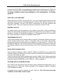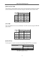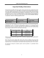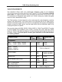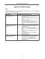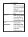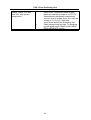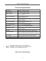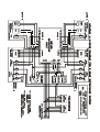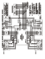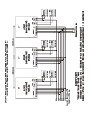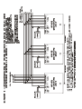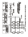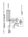
1
Bell System (Telephones) Ltd.
Presley Way, Crown Hill, Milton Keynes MK8 0ET.
Tel: 01908 261106 FAX: 01908 261116
email: [email protected] website: www.bellsystem.co.uk
PD-008 Issue 4
2 Door Switching Unit
Model 719S
719S 2 Door Switching Unit
General Description
The Model 719S Switching Unit provides a means of operating a door entry telephone
system from two entrances. Several 719S units may be combined to extend operation
up to a maximum of eight entrances.
OPERATION
When a telephone is called from a given entrance, the switching unit connects the
telephone to the speech amplifier ( model 51) of that entrance panel only. The unit
remains active for a preset period ( 30 - 120 secs), during which time the resident may
converse with the caller by lifting the telephone handset and, if required, allow the caller
to gain access, by pressing the telephone 'lock button'; the lock release (of the active
entrance only) will operate for a preset period ( 3 - 20 secs).
When a given entrance panel is in use, all other entrances are ' locked out' for the
active period (30 - 120 secs), during which time it is not possible to call any of the
telephones from these entrances. This engaged condition may be indicated to other
callers by an optional 'engaged lamp' installed at each door.
TELEPHONES
The 719S switching unit is compatible with the telephones listed below:Telephone type
Models
Diagram
801 Series
(AC/DC*)
801, 801S, 801P,
801PS
1 and 3 (AC) or
2 and 4 (DC)
500 Series
(AC)
500A, 500PA
1 and 3
500 Series
(DC)
500D, 500PD
2 and 4
500X Series
(DC)
500X, 500PX, 500LX,
500LXT, 500PLX,
500PLXT
2, 4, 5 and 6
* Only 801 Series phones manufactured after April 2000 are DC compatible.
POWER SUPPLY
The 719S is powered from a 12V AC 2A PSU (M225) for AC telephones or 12V DC 2A
PSU (M440) for DC telephones. A separate power supply is required for each 719S unit
in multi-door systems (see Diagrams 3 or 4).
It is also possible to operate a fail-safe lock release on an AC system with the addition
of a 12V DC 1A PSU (M340), see diagram 1.
1
719S 2 Door Switching Unit
A maximum of 20, 500X series telephones can be powered directly from a 719S unit.
For up to 60 telephones an additional M440 PSU must be used. Refer to diagram 6.
For larger systems contact your distributor or the manufacturer for further
guidance.
ELECTRIC LOCK RELEASE
Either fail-secure (AC/DC) or fail-safe (DC only) type electric lock releases can be
operated directly from the 719S switching unit. Use the 'FAIL SECR' connections for
fail-secure releases. Use the 'FAIL SAFE' connections for fail-safe releases and
magnetic locks. The Lock outputs are rated at a maximum current of 0.5A.
EGRESS FACILITY
An 'egress' button may be installed, on the inside of each door, to allow residents to
freely exit. Momentarily pressing this button will operate the lock release for a fixed
period (3 - 20 secs). As illustrated in diagram 1 or 2 the egress button is connected to
the 719S switching unit using the terminals marked 'EXIT'.
TRADESMAN FACILITY
The entrance panels may be ordered with an optional 'Tradesman' button to allow free
access during certain hours (used in conjunction with a time-clock). Momentarily
pressing this button will operate the lock release for a fixed period (3 - 20 secs). As
illustrated in diagrams 1 & 2, the tradesman's button should be connected in series with
the isolated contacts of a time-clock and then to the 'EXIT' terminals of the switching
unit.
DOOR STATUS INDICATION
Some models of telephone (500LX, 500LXT, 500PLX & 500PLXT) have a green LED
indicator to show the status of the entrance doors; the indicator illuminates when one
or more of the doors are open.
The door must be fitted with a suitable switch (rated 1.0A @ 12V for 60 phones) which
has normally-open contacts (ie when the door is closed). The switch is connected to the
terminals marked 'DOOR SW' on the 719S unit - refer to diagram 2.
SYSTEMS WITH 3 OR MORE DOORS
One 719S unit is required for every two doors up to a maximum of eight doors (e.g. 5
doors requires 3 x 719S units). Refer to diagram 3 (AC telephone models) or diagram
4 (DC telephone models).
A separate power supply is required for each 719S unit. The 719S units should be
installed no more than 2 metres apart.
2
719S 2 Door Switching Unit
SPEECH ACTIVE TIME
The duration for which speech remains active (from the moment a telephone is called)
can be set between 30 and 120 seconds using the PCB DIP switch marked ‘SW2':
Time
(s)
‘SW2' DIP Switch setting
3
4
30
off
off
60
on
off
90
off
on
120
on
on
LOCK TIME
The Lock Release time can be set between 3 and 20 seconds using the PCB DIP
switch ‘SW2':
Time
(s)
‘SW2' DIP Switch setting
1
2
3
off
off
5
on
off
10
off
on
20
on
on
MODE SETTING
For the system to operate correctly the operating mode MUST be set as below:
Operating Mode
SW2 DIP Switch setting
8
2 Door Switching Unit
off
Do NOT switch ‘8' on
3
719S 2 Door Switching Unit
TEST BUTTON
There are two Test buttons on the PCB marked 'TEST 1' and 'TEST 2'. Pressing the
appropriate button will force entrance 1 or 2 into an active state for a fixed period
(speech active time). Telephone models with privacy must also be buzzed to enable
speech. This feature is provided to assist in fault diagnosis during installation and
commissioning.
LED STATUS INDICATORS
To assist in testing and fault diagnosis there are 4 LED Indicators on the 719S PCB
which can be interpreted as follows:LED 1 (GREEN)
- Speech Active Door 1
LED 2 (RED)
- Lock Release Active Door 1
LED 3 (GREEN)
- Speech Active Door 2
LED 4 (RED)
- Lock Release Active Door 2
4
719S 2 Door Switching Unit
Important Safety Information
Connections to the 240V AC mains supply must be carried out by a qualified electrician
or similar competent person, and made in accordance with accepted safety practices.
A two-pole switch (as provided by a Consumer Unit or Switch-Fuse) must be included
to isolate both Live and Neutral during Installation or Maintenance. The circuit must be
protected by a fuse or other current-limiting device, rated according to the capacity of
the cable used, up to a maximum of 10A. Use only mains cable to BS6004, BS6500,
or equivalent, within the following specified limits:
Min
Max
Conductor Diameter
1.0 mm (0.8 mm2)
2.25 mm (4 mm2)
Cable Diameter
4.0 mm
8.0 mm
The Model 225, 340 or M440 Power Supply (where used) must be wall-mounted onto
plasterboard, wood or a similar non-conductive material, in a protected indoor
environment such as an electrical cupboard. The internal transformer is protected by
a fuse; always replace with the correct type and rating.
Power Supply Model
Fuse
225
T125mA 250V
340
T200mA 250V
440
T250mA 250V
The fuse must be of the 20mm glass, 250V, time delay type approved to BS EN 60127
or equivalent).
When fitting the power supply cable (both mains and low voltage) ensure the cable
entry cut-outs in the enclosure lid are no larger than necessary for the cable diameter
used and under no circumstances must they be taken beyond the outer cut-out zones.
All equipment except the entrance panel must be placed in a protected indoor
environment.
5
719S 2 Door Switching Unit
Installation
Initially connect all the equipment to one telephone ONLY. With the power applied, test
the system is fully operational. Connect one telephone at a time and test before
proceeding.
6
719S 2 Door Switching Unit
CABLE REQUIREMENTS
Use standard 0.5mm solid core twisted-pair telephone cable for all telephone
connections unless otherwise specified (e.g.BT spec # CW1308). Do not use stranded
alarm cable. For optimum speech clarity a twisted-pair should be used for the 'R' and
'O' connections to telephone and speech unit. Avoid running any cables alongside
mains or other transmission wiring.
The Total number of cores depends on the requirement for each telephone model as
shown in the table below. In all cases there is an individual call line for each phone,
while the remainder of the cores are common to all phones in the system. All telephone
models, except the 500X series, may be wired either with an individual cable or by
looping from phone to phone.
Care must be taken with 500X, 500PX, 500LX, 500PLX , 500LXT and 500PLXT models
to avoid voltage drop problems (due to LED currents from mute and door status
features). Refer to the tables on diagram 5 and below before planning the cable layout
for these models. If in doubt please contact your distributor or the manufacturer
for further guidance.
CONNECTIONS
No.
CORES
MAX
LENGTH
CONDUCTOR
DIA.
5
5
100m
100m
0.5mm
0.5mm
Telephones:
801,
500A,
801S, 801P, 801PS
500D, 500PA, 500PD
500X,
500PX
500LX, 500LXT
500PLX, 500PLXT
6
7
7
Power Supply
2
2m
2m
0.5mm (1A PSU)
1.0mm (2A PSU)
Speech unit
5
50m
0.5mm
Lock Release (up to 0.5A)
2
25m
100m
0.5mm
1.0mm
EXIT/Trades Button
(inc. Time Clock)
2
100m
0.5mm
Door Monitor Switch.
2
7
Refer to diagram 5
Refer to diagram 5
719S 2 Door Switching Unit
System Troubleshooting
NOTE
Voltages below refer to AC for AC telephone systems and DC for DC telephone
systems unless otherwise specified.
PROBLEM
COMMON CAUSE AND ACTION
Low speech volume.
!
!
!
!
!
Constant tone/feedback
when in use.
!
!
!
!
!
!
Speech not audible when
phone is buzzed.
!
!
'Vol A' or 'Vol B' adjustment required on
the Speech Unit.
Speech Unit is not tight against the panel
grill.
Panel grill is blocked.
Speech Unit supply voltage low. Check
11.5V-15V across 'C' and 'H' on unit.
More than one active telephone is off the
hook.
'Vol A' or 'Vol B' adjustment required on
the Speech Unit.
Missing 'O' connection on telephone.
Speech Unit is not tight against the panel
grill.
Entrance panel and telephone to close
together.
The entrance panel is surrounded by
reflecting walls.
Panel grill is blocked.
No/low supply to Speech Unit. Check
11.5V-15V across 'C' and 'H' on the unit.
Faulty 'R', 'O', or 'T' line between
Switching Unit and phone or Switching
Unit and panel.
8
719S 2 Door Switching Unit
Telephone will not buzz.
!
!
!
!
!
!
Lock button does not
operate release.
!
!
!
!
Tradesman/Exit button
inoperative.
!
!
Lock release operates all
the time.
!
!
!
!
Faulty 'O' or 'I' line between Switching Unit
and phone.
AC telephone systems only: Faulty ‘H’ or
‘O’ line between switching unit and panel.
As a check, short ‘H’ to ’O’ at the switching
unit and try again.
Faulty ‘V’ connection to phone. Check 1015V between ‘O’ and ‘V’ at the phone
(500LXT and 500PLXT phones ONLY).
Faulty panel button.
No/low supply to Switching Unit - Check
11.5V-15V on Switching Unit supply input.
Power supply has been wired to wrong
Switching Unit input. Check an AC supply
has been wired to a 12V AC input and a
DC supply wired to a 12V DC input, where
installed.
AC telephone systems only: Fault on ‘H’ or
‘O’ between switching unit and panel. As a
check, short ‘H’ to ‘O’ at the switching unit
and try the lock button again, when active.
Fault on 'Z' or 'O' line. Check shorting 'Z'
to 'O' at the Switching Unit, when active,
operates the release.
Lock release supply low. Check 11.5V15V across the release with the lock
button pressed and the phone active.
Using a fail-safe output but no DC power
supply present.
Time-Clock is not running or incorrectly
set (Tradesman button only).
Check connections to 'EXIT' input.
If the lock is a 'fail safe' type it has been
connected to 'FAIL SECR'/'fail secure'
output. If the lock is a 'fail secure' type it
has been connected to 'FAIL SAFE' /'fail
safe' output. Check to see if the release is
inactive when the lock button is pressed or
try swapping the connections over.
Lock button stuck down.
'Z' and 'O' lines permanently shorted
together.
'EXIT' inputs permanently shorted
together.
9
719S 2 Door Switching Unit
Supply voltage low (less
than 10V, any system
component).
!
!
Short circuit. Disconnect power supply
loads and check the output is 11.5V-15V .
Systematically disconnect components
one at a time or isolate floors, etc. until the
voltage is 11.5V-15V. Start with
connections around the Switching Unit.
Cable voltage drop too high. Try doubling
up with spare cores. Refer to the CABLE
REQUIREMENTS section.
10
719S 2 Door Switching Unit
Technical Specification
Size Boxed
238mm x 189mm x 50mm
Size PCB Only
177mm x 137mm x 18mm
Supply Voltage
11.5V - 15Vrms 50Hz AC or
11.5V - 15V DC
Current Consumption
590mA maximum AC or
290mA maxmium DC
Fail-secure Lock output
Same voltage as AC/DC supply, AC if both present.
500mA maximum.
Fail-safe Lock output
Same voltage as supply, DC only
500mA maximum
Lock release duration
3, 5, 10 or 20 seconds (typical)
Active time
30, 60, 90 or 120 seconds (typical)
Engage lamp output
Same voltage as AC/DC supply, AC if both present.
100mA maximum.
Exit input
Normally open contact (must be voltage free)
Door Switch Input
Normally open contact, when the door is closed
(must be voltage free). For DC phones only. Switch
rating must be 1.0A @12V minimum for 60 phones.
No. of Doors
2 per unit, maximum of 8 doors per system
Operating Temperature
0"C to 50"C
c
This Product complies with European Directives:
89/336/EEC for ElectroMagnetic Compatibility (EMC)
73/23/EEC for Low Voltage Systems (LVD)
Made in the United Kingdom
11