
1
General Construction
Part B – Specification and Response Requirements
Annexure 2- Minimum Design & Construction Specification
PART B
Annexure 2:
Minimum Design & Construction Specification for Class 1
Buildings
Page 1
Updated 19/07/2013
General Construction
1
1.1
Part B – Specification and Response Requirements
Annexure 2- Minimum Design & Construction Specification
INTRODUCTION ................................................................................................ 10
GENERAL CONTRACT REQUIREMENTS ..................................................................................... 10
1.2
SPECIAL REQUIREMENTS ............................................................................................................... 10
1.2.1 Generally.............................................................................................................................................. 10
1.2.2 Services ................................................................................................................................................ 10
1.2.3 Fencing................................................................................................................................................. 10
1.2.4 Disputes ............................................................................................................................................... 11
1.2.5 Environmental Control and Rubbish Removal .................................................................................... 11
1.2.6 Protection of Trees ............................................................................................................................... 11
1.2.7 Possession of Site ................................................................................................................................. 12
1.3
BRAND NAMES .................................................................................................................................... 13
1.4
APPROVING AUTHORITY (COUNCIL or DAC) REQUIREMENTS ......................................... 13
1.5
WORK HEALTH and SAFETY ........................................................................................................... 13
2. DESIGN REQUIREMENTS ................................................................................ 14
2.1
GENERAL .............................................................................................................................................. 14
2.2
SPECIFIC DESIGN REQUIREMENTS ............................................................................................. 14
2.2.1 General ................................................................................................................................................. 14
2.2.2 Maintainability ..................................................................................................................................... 14
2.2.3 Grading of Outdoor Areas.................................................................................................................... 14
2.2.3.1
General Principle ........................................................................................................................ 14
2.2.3.2
Useable Private Open Space....................................................................................................... 15
2.2.3.3
General Open Space ................................................................................................................... 15
2.2.4
Retaining Walls ................................................................................................................................... 15
2.2.5 Finished Floor Levels .......................................................................................................................... 15
2.2.6 Fencing................................................................................................................................................. 15
2.2.6.1
General ........................................................................................................................................ 15
2.2.6.2
Fence type ................................................................................................................................... 16
2.2.6.3
Existing fences ............................................................................................................................ 16
2.2.7 Paving .................................................................................................................................................. 16
2.2.7.1
Paving design .............................................................................................................................. 16
2.2.7.2
Paving Materials.......................................................................................................................... 16
2.2.7.3
Housing SA Universal Access .................................................................................................... 16
2.2.7.4
Driveways. .................................................................................................................................. 17
2.2.8 Garage or Carport. ............................................................................................................................... 17
2.2.8.1
General ....................................................................................................................................... 17
Page 2
Updated 19/07/2013
General Construction
Part B – Specification and Response Requirements
Annexure 2- Minimum Design & Construction Specification
2.2.8.2
Carports ...................................................................................................................................... 17
2.2.8.3
Garages....................................................................................................................................... 17
2.2.9 Clothes Lines ....................................................................................................................................... 18
2.2.10
Storm Water / Site Water Disposal .................................................................................................. 18
2.2.10.1 General ........................................................................................................................................ 18
2.2.10.2 Retention and Detention Tanks ................................................................................................... 19
2.2.10.3 Detention Special Regulatory Requirements............................................................................... 19
2.2.11
Bathrooms........................................................................................................................................ 20
2.2.11.1 Bathroom Special items .............................................................................................................. 20
2.2.12
House Fabric .................................................................................................................................... 20
2.2.12.1 Floors .......................................................................................................................................... 21
2.2.12.2 Footings ....................................................................................................................................... 21
2.2.12.2.1 Bore logs .............................................................................................................................. 21
2.2.12.2.2 Proposal Footing Design ...................................................................................................... 21
2.2.12.2.3 Footing Design ..................................................................................................................... 22
2.2.12.3 External Walls ............................................................................................................................. 22
2.2.121.4
Internal Walls .......................................................................................................................... 22
2.2.12.5 Internal Ceilings .......................................................................................................................... 22
2.2.12.6 External Linings .......................................................................................................................... 23
2.2.12.7 Roofs & Gutters .......................................................................................................................... 23
2.2.12.8 Future Room Airconditioner. ...................................................................................................... 23
2.2.12.9 Heaters ........................................................................................................................................ 23
2.2.13
Site lighting ..................................................................................................................................... 23
2.2.14
Termite Protection ........................................................................................................................... 23
2.2.15 Bushfire Protection.............................................................................................................................. 23
3
CONSTRUCTION REQUIREMENTS ................................................................. 25
3.1
General .................................................................................................................................................... 25
3.1.1 Application........................................................................................................................................... 25
3.1.2 Approvals ............................................................................................................................................. 25
3.1.3 Fees and charges .................................................................................................................................. 25
3.1.4 Insurance .............................................................................................................................................. 25
3.1.5 Site issues ............................................................................................................................................. 25
3.1.6 Mandatory Notification stages for Inspections .................................................................................... 26
3.1.7 Manuals ................................................................................................................................................. 27
3.2
SITEWORKS ......................................................................................................................................... 27
3.2.1 Existing sites ........................................................................................................................................ 27
3.2.2 Site Clearing ........................................................................................................................................ 27
3.2.3 Trees .................................................................................................................................................... 28
3.2.4 Demolition ........................................................................................................................................... 28
3.2.5 Services ................................................................................................................................................ 28
3.2.6 Site levels and benching (refer “Standard Details”) ............................................................................. 28
3.2.7 Stormwater Drainage ........................................................................................................................... 28
3.2.8 Imported site fill ................................................................................................................................... 28
3.2.9 Retaining walls .................................................................................................................................... 28
3.2.9.1
Pier and Steel Beam Retaining Walls.......................................................................................... 29
3.2.9.2
Retaining Walls combined with Fence Posts .............................................................................. 29
3.2.9.3
Landscaping retaining walls - fencing....................................................................................... 29
3.2.10
Garden areas .................................................................................................................................... 29
3.2.11
Landscaping ..................................................................................................................................... 29
3.2.12
Completion ...................................................................................................................................... 29
3.3
CONCRETE ........................................................................................................................................... 30
3.3.1 Standard of Work ................................................................................................................................. 30
3.3.2 Materials .............................................................................................................................................. 30
3.3.3 Excavation For Footings ...................................................................................................................... 30
3.3.4 Termite Treatment ............................................................................................................................... 30
Page 3
Updated 19/07/2013
General Construction
Part B – Specification and Response Requirements
Annexure 2- Minimum Design & Construction Specification
3.3.4.1
General ........................................................................................................................................ 30
3.3.4.2
Special Requirements for Bath and similar Risers: ..................................................................... 31
3.3.4.3
Perimeter Protection ................................................................................................................... 31
3.3.5 Concrete Mix ....................................................................................................................................... 31
3.3.5.1
General ........................................................................................................................................ 31
3.3.5.2
Concrete Class ............................................................................................................................. 31
3.3.5.3
Delivery of Pre-Mixed Concrete ................................................................................................. 31
3.3.5.4
Site Mixed Concrete .................................................................................................................... 31
3.3.6 Tests ..................................................................................................................................................... 32
3.3.7 Formwork............................................................................................................................................. 32
3.3.7.1
Generally ..................................................................................................................................... 32
3.3.7.2
Treatment .................................................................................................................................... 32
3.3.7.3
Stripping ...................................................................................................................................... 32
3.3.7.4
Stripped Surfaces ........................................................................................................................ 32
3.3.8 Reinforcement Generally ..................................................................................................................... 32
3.3.8.1
General Conditions ...................................................................................................................... 32
3.3.8.2
Lapping ....................................................................................................................................... 33
3.3.8.3
Cover ........................................................................................................................................... 33
3.3.9 Preparation Before Pour ....................................................................................................................... 33
3.3.9.1
Inspection .................................................................................................................................... 33
3.3.9.1
Joining To Existing Slabs ............................................................................................................ 33
3.3.9.3
Items to be in Position ................................................................................................................. 33
3.3.10
Paving (Including Driveways) ......................................................................................................... 33
3.3.10.1 General ........................................................................................................................................ 33
3.3.10.2 Finished Levels ........................................................................................................................... 33
3.3.10.3 Tooled Joints ............................................................................................................................... 34
3.3.11
Floor Finished Levels ...................................................................................................................... 34
3.3.12
Type of Concrete Works .................................................................................................................. 34
3.3.12.1 Footings ....................................................................................................................................... 34
3.3.12.2
Steps, Landings and Ramps .................................................................................................... 35
3.3.12.3 Perimeter Paving ......................................................................................................................... 35
3.3.12.3
Driveway Paving..................................................................................................................... 35
3.3.13
Construction Details ........................................................................................................................ 35
3.3.13.1 Dowelled Construction Joints (DCJ) ........................................................................................... 35
3.3.13.2 Sealant to DCJ ............................................................................................................................. 36
3.3.13.3 Separation of Paving ................................................................................................................... 36
3.3.13.4 Crossovers ................................................................................................................................... 36
3.3.14
Concrete Finishes ............................................................................................................................ 36
3.3.14.1 General ........................................................................................................................................ 36
3.3.14.2
Surface to be Tiled .................................................................................................................. 36
3.3.14.3 Surface to be Topped.................................................................................................................. 36
3.3.15
Placing Concrete .............................................................................................................................. 36
3.3.15.1 Generally ..................................................................................................................................... 36
3.3.15.2 Severe Weather Conditions ......................................................................................................... 37
3.3.16
Protection And Curing ..................................................................................................................... 37
3.3.16.1 General ........................................................................................................................................ 37
3.3.16.2 Retention of Bond ....................................................................................................................... 37
3.3.16.3
Additional Protection .............................................................................................................. 37
3.3.17
Rainwater Tank Stand ..................................................................................................................... 37
3.3.17.1 Tank Stand for Rainwater tank plumbed to toilets (usually 1000 Litres) .................................... 38
3.3.17.2 Tank Stand for Detention tank .................................................................................................... 38
3.3.18
Reinstatement .................................................................................................................................. 38
3.4
MASONRY CONSTRUCTION ............................................................................................................ 38
3.4.1 Workmanship And Materials ............................................................................................................... 38
3.4.1.1
Standard of Workmanship and Materials .................................................................................... 38
3.4.2 Masonry Units...................................................................................................................................... 38
3.4.2.1
Uniformity ................................................................................................................................... 38
3.4.2.2
Clay Bricks .................................................................................................................................. 39
3.4.2.3
Concrete Blocks & Bricks ........................................................................................................... 39
Page 4
Updated 19/07/2013
General Construction
Part B – Specification and Response Requirements
Annexure 2- Minimum Design & Construction Specification
3.4.2.4
Aerated Autoclaved Concrete (AAC) ......................................................................................... 39
3.4.2.5
Natural Stone ............................................................................................................................... 39
3.4.3 Mortar .................................................................................................................................................. 39
3.4.3.1 Materials .......................................................................................................................................... 39
3.4.3.2
Mortar Mixes ............................................................................................................................... 39
3.4.3.3
Mixing ......................................................................................................................................... 39
3.4.4 Damp Proofing ..................................................................................................................................... 39
3.4.4.1
Damp Proof Membrane and Flashings ........................................................................................ 39
3.4.5 Curing Period ....................................................................................................................................... 40
3.4.6 Wall Construction ................................................................................................................................ 40
3.4.6.1
Laying ......................................................................................................................................... 40
3.4.6.2
Gabled Walling on Boundary ...................................................................................................... 40
3.4.6.3
Closing of Cavity ........................................................................................................................ 40
3.4.6.4
Junction of Walls Internal & External ......................................................................................... 40
3.4.6.5
Party Walls .................................................................................................................................. 41
3.4.6.6
Reinforced Work ......................................................................................................................... 41
3.4.6.7
Chasing........................................................................................................................................ 41
3.4.7 Joints .................................................................................................................................................... 41
3.4.7.1
Fair Face Work............................................................................................................................ 41
3.4.7.2
Rendered Work ........................................................................................................................... 41
3.4.7.3
Articulated Joints ........................................................................................................................ 41
3.4.8 Ties and Reinforcement ....................................................................................................................... 41
3.4.8.1
Wall Ties ..................................................................................................................................... 41
3.4.8.2
Spacing of Wall Ties ................................................................................................................... 42
3.4.8.3
Door Strap Ties ........................................................................................................................... 42
3.4.8.4
Roof Ties in Solid Masonry ............................................................................................................... 42
3.4.8.4.1 Wall Plate Fixing ................................................................................................................... 42
3.4.8.4.2 Tie Down Fixing .................................................................................................................... 42
3.4.8.5
Reinforcement ............................................................................................................................. 42
3,4.9 Ventilation ........................................................................................................................................... 42
3.4.9.1
Cavity Ventilation ....................................................................................................................... 43
3.4.9.2
Ventilation Under Suspended Floors .......................................................................................... 43
3.4.10
Building In ....................................................................................................................................... 43
3.4.10.1 General ........................................................................................................................................ 43
3.4.11
Sills And Copings ............................................................................................................................ 43
3.4.11.1 General ........................................................................................................................................ 43
3.4.12
Lintels .............................................................................................................................................. 43
3.4.12.1 Steel Lintels for Masonry ............................................................................................................ 43
3.4.12.2 Block Lintels and Bond Beams ................................................................................................... 44
3.4.13
Reinforced Brick Piers..................................................................................................................... 44
3.4.14
Provision For AC Unit ..................................................................................................................... 44
3.4.15
Cleaning And Pointing .................................................................................................................... 44
3.4.15.1 Making Good and Pointing ......................................................................................................... 44
3.4.15.2 Cleaning ...................................................................................................................................... 44
3.4.16
Rendering ........................................................................................................................................ 44
3.4.16.1 Workmanship .............................................................................................................................. 44
3.4.16.2 Materials...................................................................................................................................... 44
3.4.16.3 Mixing ......................................................................................................................................... 44
3.5
WALL, FLOOR and ROOF FRAMING ............................................................................................. 45
3.5.1 Workmanship ....................................................................................................................................... 45
3.5.2 Wall Framing ....................................................................................................................................... 45
3.5.2.1
General Requirements ................................................................................................................. 45
3.5.2.2
Timber ......................................................................................................................................... 46
3.5.2.3
Steel ............................................................................................................................................. 46
3.5.2.4
Wall Openings and Beams .......................................................................................................... 46
3.5.2.5
Junctions with Concrete Floors ................................................................................................... 46
3.5.2.6
Provision for Fixtures .................................................................................................................. 46
3.5.3 House Roofs And Ceilings ................................................................................................................... 47
Page 5
Updated 19/07/2013
General Construction
Part B – Specification and Response Requirements
Annexure 2- Minimum Design & Construction Specification
3.5.3.1
General Requirements ................................................................................................................. 47
3.5.3.2
Roof Trusses................................................................................................................................ 47
3.5.4 Porches, Verandahs, Carports And The Like ....................................................................................... 47
3.5.4.1
General Requirements ................................................................................................................. 47
3.5.4.2
Posts ............................................................................................................................................ 47
3.5.5 Eaves And Soffits ................................................................................................................................ 47
3.5.5.1
General Items. ............................................................................................................................. 47
3.5.5.2
Timber Fascias ............................................................................................................................ 48
3.5.5.3
Metal Fascias ............................................................................................................................... 48
3.5.5.4
Barge Details ............................................................................................................................... 48
3.5.5.5
Soffit Linings .............................................................................................................................. 48
3.5.6 Ceiling Access ..................................................................................................................................... 48
3.5.6.1
Standard Detail Access................................................................................................................ 48
3.5.7 External Wall Cladding........................................................................................................................ 48
3.5.7.1
General ........................................................................................................................................ 48
3.5.7.2
Hardiplank ................................................................................................................................... 48
3.5.7.3
Weathertex Plank ........................................................................................................................ 49
3.5.7.4
Timber Boarding ......................................................................................................................... 49
3.5.7.5
F.R.C.B. Sheet Wall Lining ........................................................................................................ 49
3.5.7.6
Other Wall Lining ....................................................................................................................... 49
3.5.8 Floor Construction ............................................................................................................................... 49
3.5.8.1
Preparation and Clearance Under Suspended Ground Floors ..................................................... 49
3.5.8.2
Timber Sizes................................................................................................................................ 49
3.5.8.3
Steel Sizes ................................................................................................................................... 49
3.5.9 Upper Floor Framing - 2 Storey Housing ............................................................................................ 49
3.5.9.1
General Requirements ................................................................................................................. 50
3.5.9.2
Steel Members ............................................................................................................................ 50
3.5.9.3
Timber Beams ............................................................................................................................. 50
3.5.9.4
Joists ............................................................................................................................................ 50
3.5.10
Flooring ........................................................................................................................................... 50
3.5.10.1 Particle Board/Plywood Flooring ................................................................................................ 50
3.5.10.2 Wet Area Flooring....................................................................................................................... 51
3.5.10.3 Strip (or Board) Floors ................................................................................................................ 51
3.6
INTERNAL LININGS AND TRIM ...................................................................................................... 51
3.6.1 Linings Generally................................................................................................................................. 51
3.6.2
Wet Areas ........................................................................................................................................... 51
3.6.3 Plasterboard ......................................................................................................................................... 51
3.6.3.1
Sheet Material ............................................................................................................................. 52
3.6.3.1
Flushing ....................................................................................................................................... 52
3.6.4 Fibre Cement Board ............................................................................................................................. 52
3.6.4.1
Sheet Material ............................................................................................................................. 52
3.6.4.2
Flushing ....................................................................................................................................... 52
3.6.5 Cornices And Vents ............................................................................................................................. 52
3.6.5.1
Plasterboard Cornice ................................................................................................................... 52
3.6.5.1
Vents ........................................................................................................................................... 52
3.6.6 Timber Mouldings ............................................................................................................................... 52
3.6.7.1
General ........................................................................................................................................ 53
3.6.7.2
Scratch Resistance ....................................................................................................................... 53
3.6.7.3
Impact Resistance Low Level ..................................................................................................... 53
3.6.7.4
Impact Resistance Full Height .................................................................................................... 53
3.7
INSULATION......................................................................................................................................... 54
3.8.
WINDOWS ............................................................................................................................................. 54
3.8.1
General ................................................................................................................................................ 54
3.8.2
Aluminium windows ........................................................................................................................... 54
3.8.2.1
General ........................................................................................................................................ 54
3.8.2.2
Finish ........................................................................................................................................... 54
3.8.3 Protection ............................................................................................................................................. 55
Page 6
Updated 19/07/2013
General Construction
3.8.4
3.8.5
Part B – Specification and Response Requirements
Annexure 2- Minimum Design & Construction Specification
Hardware and Seals.............................................................................................................................. 55
Flyscreens ............................................................................................................................................ 55
3.9
DOORS.................................................................................................................................................... 55
3.9.1 Types, sizes and finishes ...................................................................................................................... 55
3.9.1.1
Thickness .................................................................................................................................... 55
3.9.1.2
Standard of Manufacture ............................................................................................................. 55
3.9.1.3
Types of Doors ............................................................................................................................ 55
3.9.1.4
Hardware ..................................................................................................................................... 56
3.9.2
Timber door frames and jambs ........................................................................................................... 57
3.9.3
Metal door frames and jambs .............................................................................................................. 57
3.9.4
Flyscreen Doors (To hinged doors)..................................................................................................... 58
3.9.5
Door seals and thresholds ................................................................................................................... 58
3.9.6
Door stops ........................................................................................................................................... 58
3.9.7 Locks and Door Furniture .................................................................................................................... 58
3.9.7.1
Complying Locks and Door Furniture ........................................................................................ 59
3.9.7.2
Mounting Heights........................................................................................................................ 59
3.9.7.3
Keying ......................................................................................................................................... 59
3.10
JOINERY ................................................................................................................................................ 59
3.10.1
General ............................................................................................................................................ 59
3.10.2
Cupboards ........................................................................................................................................ 60
3.10.2.1 General ........................................................................................................................................ 60
3.10.2.2 Method of Assembling ................................................................................................................ 60
3.10.2.3 Bench Units ................................................................................................................................. 60
3.10.2.4 Drawers ....................................................................................................................................... 61
3.10.2.5 Doors ........................................................................................................................................... 61
3.10.2.6 Linen, Wardrobe and Utility Cupboards ..................................................................................... 61
3.10.2.7 Installation ................................................................................................................................... 61
3.10.2.8 Door Hardware ........................................................................................................................... 61
3.11
HARDWARE .......................................................................................................................................... 62
3.11.1
Metal Cabinets ................................................................................................................................. 62
3.11.2
House Numbers ............................................................................................................................... 62
3.11.3
Bathroom Accessories ..................................................................................................................... 62
3.11.3.1 General ........................................................................................................................................ 62
3.11.3.2 Shower Curtain Rail .................................................................................................................... 62
3.11.3.3 Bathroom mirror.......................................................................................................................... 62
3.11.3.4 Towel rails ................................................................................................................................... 62
3.11.3.5 Grab rails including hand held showers attached to a grab rail ................................................... 63
3.11.3.6 Soap holder/WC toilet roll holder ............................................................................................... 63
3.11.3.7 Vanity basin – All houses............................................................................................................ 63
3.12. GLAZING ............................................................................................................................................... 63
3.12.1
Shower Screens ............................................................................................................................... 63
3.13. TILING ................................................................................................................................................... 64
3.13.1
Water-proofing ................................................................................................................................ 64
3.13.2
Falls ................................................................................................................................................. 64
3.13.3
Colour scheme ................................................................................................................................. 64
3.13.4
Tiles ................................................................................................................................................. 64
3.13.5
Floor tiling ....................................................................................................................................... 65
3.13.6
Wall tiling ........................................................................................................................................ 65
3.13.7
Replacement wall tiles ..................................................................................................................... 66
3.13.8
Threshold and porch tiles................................................................................................................. 66
3.14
ROOFING ............................................................................................................................................... 66
3.14.1
Standards ......................................................................................................................................... 66
3.14.2
Warranty .......................................................................................................................................... 66
3.14.3
Adverse conditions .......................................................................................................................... 66
Page 7
Updated 19/07/2013
General Construction
3.14.4
3.14.5
3.14.6
3.14.7
3.14.8
Part B – Specification and Response Requirements
Annexure 2- Minimum Design & Construction Specification
Roofing system and materials .......................................................................................................... 67
Eaves ............................................................................................................................................... 67
Roof Lights (Skylights) ................................................................................................................... 67
Downpipes ....................................................................................................................................... 67
Gutters ............................................................................................................................................. 67
3.15
PAINTING .............................................................................................................................................. 67
3.15.1
Materials and finishes ...................................................................................................................... 67
3.15.2
Paint Types ...................................................................................................................................... 68
3.15.2.1 Timber And Timber Products...................................................................................................... 68
3.15.2.2
Metalwork And Unplasticised Pvc ......................................................................................... 69
3.15.2.3
Internal Walls And Ceilings................................................................................................... 70
3.15.2.4
External Walls And Soffits .................................................................................................... 71
3.15.2.5
Fencing .................................................................................................................................... 71
3.15.2.6
Carpark Line Marking ............................................................................................................... 71
3.15.3
Colours ............................................................................................................................................ 71
3.16
PLUMBING ............................................................................................................................................ 71
3.16.1
Standards and approvals .................................................................................................................. 71
3.16.2
General ............................................................................................................................................ 71
3.16.3
External water service ..................................................................................................................... 72
3.16.3.1 Materials...................................................................................................................................... 72
3.16.3.2 General ........................................................................................................................................ 72
3.16.3.3 Group Sites .................................................................................................................................. 72
3.16.4
Fire Service ...................................................................................................................................... 72
3.16.5
Fire Mains ........................................................................................................................................ 73
3.16.6
Fire Hydrant and Standpipe. ............................................................................................................ 73
3.16.7
Site stormwater drainage ................................................................................................................. 74
3.16.8
Stormwater Retention/Detention ..................................................................................................... 74
3.16.8.1 General ........................................................................................................................................ 74
3.16.8.2 Tanks ........................................................................................................................................... 74
3.16.8.3 Roof plumbing ............................................................................................................................ 75
3.16.8.4 Pipework from Rainwater tank to Cistern. .................................................................................. 75
3.16.8.5 Cover to Pipework....................................................................................................................... 75
3.16.8.6 Isolating Valves ........................................................................................................................... 75
3.16.8.7 Toilet cisterns .............................................................................................................................. 75
3.16.8.8 Detention ..................................................................................................................................... 75
3.16.9
Fixtures ............................................................................................................................................ 75
3.16.10
Cocks and Fittings .......................................................................................................................... 76
3.16.10.1
Tapware .................................................................................................................................. 76
3.16.10.2
Finish ...................................................................................................................................... 76
3.16.10.3
Breeching Pieces ..................................................................................................................... 76
3.16.10.4
Schedule of Taps..................................................................................................................... 76
3.16.11 Hot water service ............................................................................................................................. 78
3.16.11.1 Hot Water Units ............................................................................................................................ 78
3.16.11.2 Installation .................................................................................................................................... 79
3.16.11.3 Termination points ........................................................................................................................ 79
3.16.12
Floor traps....................................................................................................................................... 81
3.17
ELECTRICAL ....................................................................................................................................... 81
3.17.1
Standards and Approvals ................................................................................................................. 81
3.17.2
Generally ......................................................................................................................................... 82
3.17.3
Electrical supply for group housing ................................................................................................. 82
3.17.4
Individual houses - Meters............................................................................................................... 82
3.17.5
For Community and Group titled units- Meters .............................................................................. 82
3.17.6
Earthing System ............................................................................................................................... 83
3.17.7
Load centre ...................................................................................................................................... 83
3.17.8
Power ............................................................................................................................................... 85
3.17.9
Power and light switch-mounting heights (to centre lines).............................................................. 85
3.17.10 Lighting ........................................................................................................................................... 85
Page 8
Updated 19/07/2013
General Construction
Part B – Specification and Response Requirements
Annexure 2- Minimum Design & Construction Specification
3.17.11 Site lighting ..................................................................................................................................... 86
3.17.12 Exhaust fans..................................................................................................................................... 86
3.17.13 Cooking Appliances, Gas or Electric Upright Cookers ................................................................... 86
3.17.13.1
General .................................................................................................................................... 86
3.17.13.2
Cooker Models........................................................................................................................ 87
3.17.13.3
Gas Termination. .................................................................................................................... 87
3.17.13.4 Electrical Termination ................................................................................................................. 87
3.17.14 Telephone ........................................................................................................................................ 87
3.17.15 National Broadband Network (NBN) .............................................................................................. 88
3.17.15.1 Generally...................................................................................................................................... 88
3.17.15.2 External Requirements ................................................................................................................. 88
3.17.15.3 Internal Requirements .................................................................................................................. 88
3.17.15.4 Conduits ....................................................................................................................................... 88
3.17.16 Smoke Detectors .............................................................................................................................. 92
3.17.17 Television points.............................................................................................................................. 92
3.18
GAS.......................................................................................................................................................... 92
3.18.1
Generally ......................................................................................................................................... 92
3.18.2
Gas service....................................................................................................................................... 92
3.18.2.1 Provision for future gas room heater. .................................................................................................. 92
3.19
PAVING .................................................................................................................................................. 93
3.19.1
General ............................................................................................................................................ 93
3.19.2
Crossovers ....................................................................................................................................... 93
3.19.3
Concrete paving ............................................................................................................................... 93
3.19.4
Driveway and carport paving........................................................................................................... 93
3.19.5
Unit paving ...................................................................................................................................... 93
3.20
CLOTHES LINE .................................................................................................................................... 94
3.21
FENCING ............................................................................................................................................... 94
3.21.1
Notifications .................................................................................................................................... 94
3.21.2
Site fencing generally ...................................................................................................................... 94
3.21.3
Rear screen fencing ......................................................................................................................... 95
3.21.4
Front Fencing/Gates ........................................................................................................................ 96
3.21.5
Concrete for Fence Posts ................................................................................................................. 96
3.22
LETTERBOXES .................................................................................................................................... 96
3.22.1
General ............................................................................................................................................ 96
3.22.1
Letterboxes for Group sites ............................................................................................................. 96
3.22.2
Letter Boxes to Individual Houses on Torrens Title Allotments ..................................................... 96
STANDARD DETAILS ............................................................................................ 102
Page 9
Updated 19/07/2013
General Construction
1
Part B – Specification and Response Requirements
Annexure 2- Minimum Design & Construction Specification
INTRODUCTION
1.1
GENERAL CONTRACT REQUIREMENTS
All proposals shall comply with this ”Minimum Specification” together with any additional
requirements issued by the Trust with the tender call and any encumbrances, envelopes,
“Building Guidelines” and Council requirements to which the proposed land is subject.
Comply with the current requirements of all current legislation and authorities including but
not limited to:
The Real Property Act
Development Act
Building Code of Australia as it applies to South Australia
SA Water or Water Industry
SA Power Networks
NBN Co
Telstra
Department of Health
Safework SA
Office of the Technical Regulator
Any Local Authority, statutory or other authorised body having jurisdiction over the work
Where approvals have been obtained by the Trust prior to tender call, the details of these will
be included in ”Part B - Specification& Response Requirements ANNEXURE 1”
1.2
SPECIAL REQUIREMENTS
1.2.1
Generally
Contracts may be adjacent to other Trust properties and/or have private adjoining owners.
Builders shall respect the privacy of all of those residents and shall make an appropriate
allowance in their proposals for managing their projects with minimum disruption and
inconvenience to them.
Where allotments have been created as vacant land by way of demolition of a previous
dwelling or dwellings (refer “Proposal Information Notice”), proponents should be aware that
footings and redundant services may still exist and may be encountered during the
construction activities for the new houses.( refer Clause 3.2.1)
1.2.2
Services
Where disruptions are made to existing services, especially water and electricity, the
Proponent shall notify tenants and adjoining owners or occupiers of the restriction well in
advance of the occurrence and shall minimise the disruption.
1.2.3
Fencing
The Proponent shall issue Fencing Notices complying with the Fences Act and ensure that
all fencing/retaining wall issues are discussed and resolved with adjoining owners/occupiers
prior to any work being carried out to minimise cause for complaint. Ensure that privacy and
security of the neighbour(s) is maintained at all times.
Page 10
Updated 19/07/2013
General Construction
Part B – Specification and Response Requirements
Annexure 2- Minimum Design & Construction Specification
Tenants and adjoining owners or occupiers shall be notified of the date when fencing is to be
demolished and renewed. Provide temporary fencing to secure yard spaces when fencing is
to be removed and/or replaced.
1.2.4
Disputes
The Contractor shall make the site supervisor known to all tenants/adjoining owners or
occupiers so that complaints or disputes can be effectively managed.
Should any site work result in a dispute or require rectification work to adjoining properties,
the Contractor shall resolve the dispute and carry out the rectification work required prior to
Practical Completion.
The Contractor should be aware that some sites might involve elderly tenants or owners or
occupiers with particular concerns regarding noise, security and safety. Manage the project
and adjust work times to address these concerns.
1.2.5
Environmental Control and Rubbish Removal
Builders shall not use adjoining properties or the footpath or road reserve as a work area or
for the storage of materials, site rubbish or fill.
Sites shall be kept clean and tidy at all times and a safe working environment is to be
maintained.
Debris and waste material shall be cleared periodically from the site. Contractors are
encouraged to use waste bins or wire mesh rubbish traps to contain loose material.
Contractors shall comply with local Council ordinances or requirements set out in
Development Guidelines with respect to waste management. Where ever possible waste is
to be sorted and recycled.
During construction, the contractor shall ensure that mud and debris shall not be carried by
vehicles and deposited on adjacent properties or Council footpaths paths and roads when
leaving the site.
Construct temporary drains or other means to control site storm water to ensure water, mud
or debris is not shed onto adjoining properties or cause inundation or ponding of water on or
around the site.
1.2.6
Protection of Trees
Contractors are urged to inform themselves of their obligations in relation to the protection of
significant or regulated trees.
All contractors who are engaged under the contract or who may be engaged under contract,
with SAHT, are to be aware of the conditions and implications of the Development Act and
shall operate in accordance with the provisions under the Act.
Under no circumstances shall any contractor, their sub-contractor or their employees,
undertake work in any form which may contravene the Act.
No tree on SAHT land will be pruned, lopped, cut down, removed or damaged in any way
unless authorised. This extends to any ground works, which may expose or damage any
root system. (ie digging footings, service pipe trenches, footings for retaining walls and
fences, cut and fill operations).
Page 11
Updated 19/07/2013
General Construction
Part B – Specification and Response Requirements
Annexure 2- Minimum Design & Construction Specification
Contractors should note these conditions apply also to any trees adjacent any SAHT land,
such as trees on Council property, street trees and trees on neighbour’s land.
1.2.7
Possession of Site
Prior to commencement on site of any work, SAHT will issue a “Possession of Site Notice”
(DPS) to the contractor. DPS will not be issued to the contractor until the contract has been
signed and executed.
Prior to the issue of DPS, the contractor must provide current Contractors All Risks and
Public Liability Insurances which must be maintained and current throughout the period of
the contract.
No work on site shall commence until a Possession of Site Notice has been issued, and the
site has been jointly inspected by both a representative of the contractor and someone
authorised by SAHT.
At the site inspection the SAHT representative will:
1. Ascertain with the contractor the position of any existing trees and whether any tree
on or adjacent the site is deemed a “significant tree”. Any trees identified for
retention, significant or otherwise will be adequately protected from damage during
the currency of the contract. Contractors are reminded that significant financial
penalties exist for breaches of the Development Act;
2. Ensure all Work Health and Safety (WHS) requirements are met;
3. Inspect all boundary fences to determine those which need replacement or
alteration;
4. Reinforce the issuing of fencing notices to applicable neighbours;
5. Reinforce the requirements when working on council or neighbouring properties.
6. Check for Sewer and Water connections (all coordinated and paid for by SAHT);
7. Check for any gas and electrical connections;
8. Check for any over head wires or other obstructions or near the site;
9. Locate all boundary marks including survey pegs and metal pins;
10. Identify Permanent Survey Markers and Temporary Bench Marks.
11. Issue the contractors representative with a copy of the identification survey, showing
all boundary marks and a copy of the sewer and water service locations;
12. Arrange with Senior Property Officer (SAHT) to remove any rubbish from site and
cut grass if necessary;
13. Reinforce the requirements relating to rainwater tanks connected to toilets and
stormwater detention;
Page 12
Updated 19/07/2013
General Construction
Part B – Specification and Response Requirements
Annexure 2- Minimum Design & Construction Specification
14. Discuss and agree any variations to the plans; and
15. Mark on the site plan, and photograph, any dilapidation of the council infrastructure
outside the front boundary (and side boundary if a corner allotment).
1.3
BRAND NAMES
The use of brand names included in the tender documents are given as examples of items
that comply with Trust requirements. They generally do not indicate a preference for that
brand or type but instead are nominated due to their specifications, details and requirements
for a particular circumstance or function.
Other manufacturers may have similar products which may be suitable. Should a Proponent
wish to use an alternate product the Proponent must demonstrate in writing that the alternate
product is equivalent to the brand name product and will provide equal to or better than the
serviceable life of the specified product . Such requests must include the full details of the
proposed product and sufficient technical information to enable the Trust to make an
informed assessment without seeking further information. The Proponent will be advised in
writing if the alternative product is accepted or not.
Unless an alternate product has been accepted in writing, the specified brand name product
must be used.
1.4
APPROVING AUTHORITY (COUNCIL or DAC) REQUIREMENTS
While SAHT minimum requirements are contained within this specification council or DAC
may have other requirements that take precedence. The areas that are particularly
highlighted are in the area of planning, heritage, stormwater control (including detention) and
bush fire provisions. The proponent is to meet all requirements of the approving authority
1.5
WORK HEALTH and SAFETY
Your attention is drawn to the requirements in the Work Health and Safety Act and
Regulations.
Particular attention is to be taken to ensure that the design and construction of the houses
ensures that all the requirements are met. In particular, as required by the legislation, the
houses shall be designed and constructed in a way that they can be safely built maintained
and demolished and documentation demonstrating that is to be provided to the principal
before any work is to commence on the construction of the building.
As required by the legislation the methods of safely operating and maintaining the building
are to be discussed and agreed with SAHT and written documentation of the safe methods of
maintaining the building shall be provided.
Any anchor points or other built in devices that need to be provided to enable the building to
be maintained safely and economically shall be included in the construction of the building.
Page 13
Updated 19/07/2013
General Construction
2.
Part B – Specification and Response Requirements
Annexure 2- Minimum Design & Construction Specification
DESIGN REQUIREMENTS
2.1
GENERAL
This specification shall be for Class 1 buildings as defined by the Building Code of Australia
Housing SA has produced a number of design guidelines. These are accessible on the
Department of Communities and Social Inclusion web site. And more specifically
http://www.dcsi.sa.gov.au/services/housing-sa/housing-design-guidelines
All proponents need to familiarize themselves with all the guidelines. These guidelines
provide the background for the designs. Where there is a conflict the requirements within
this document and the general guide lines this document shall take precedent.
2.2
SPECIFIC DESIGN REQUIREMENTS
2.2.1
General
The design requirements as given in House Design Guide 1.1, Housing Accommodation
Schedules 1.4 and Housing SA Universal Design Criteria 2.3 which are attached shall be
followed unless the ”Part B - Specification & Response Requirements ANNEXURE 1” specify
otherwise.
Any specific design requirements that apply to a contract are given in”Part B - Specification &
Response Requirements ANNEXURE 1”
In addition designers are to allow for all items specified in SECTION 3 CONSTRUCTION
REQUIREMENTS. The minimum requirements within the guides shall be considered as
fixed minimums for this type of housing.
2.2.2
Maintainability
Public housing is generally used as rental property for a significant part of its life. The
maintenance of the property is the responsibility of the South Australian Housing Trust.
Proponents are to consider in their designs the costs relating to ongoing maintenance and
are to ensure that their proposals are low maintenance.
In particular consideration is to be given to :• Using materials that require minimal maintenance
• Using low maintenance finishes
• Ensuring that there is the appropriate access to maintain the building and services.
2.2.3
Grading of Outdoor Areas
2.2.3.1
General Principle
Where possible bench sloping sites to form a single near level private yard space adjacent to
the main living areas of the house/unit and to perimeter paving and driveways.
Page 14
Updated 19/07/2013
General Construction
2.2.3.2
Part B – Specification and Response Requirements
Annexure 2- Minimum Design & Construction Specification
Useable Private Open Space
The useable rectangular area specified in the Design Guide is to be sloped at flatter than 1 in
50 and appropriately drained to the storm water system. It is to be in addition to and have
stepless access from the perimeter paving.
2.2.3.3
General Open Space
On very steep blocks and subject to Trust approval it may be acceptable to bench the rest of
the yard area to a maximum gradient of 1:14 or it may be acceptable to incorporate retained
steps in the benched site provided access to the whole of the site is achieved, with maximum
gradients to each part of the site of 1:14.
Where steps in the benched site are approved they shall be linked by paved concrete ramps
not steeper than1:14. Steeper short ramps designed in accordance with the requirements of
AS 1428.1 may be used subject to specific written SAHT approval.
All out door areas are to be graded away from the house and drained towards sumps
connected to the storm water system. Front yards may graded to the street without any
sumps where levels permit.
2.2.4
Retaining Walls
Locate retaining walls under the fence line or more than 1000 mm from the fence line.
Where the site works creates level differences between the site and the adjoining properties
provide an edging or retaining wall under the fence.
Where the difference is greater than 200 mm a retaining wall, rather than an edging, is
required. All materials used as kerbs or retaining walls must be durable. Reinforced concrete
or galvanized steel posts with reinforced concrete sleepers are the preferred options.
Timber sleeper walls are not to be used but other durable systems can be designed for
landscaping walls. Standard details of acceptable walls are attached.
Provide an engineering design and Building Rules approval for all retaining walls to be
included as part of the contract documents..
2.2.5
Finished Floor Levels
Unless a rear of allotment stormwater connection is available set the FFL level for all
houses/units a minimum of 300mm above the top of the kerb level to allow for site drainage
to the street. The lowest point on the kerb in front of the house or allotment may be used.
On group sites the floor levels of units further from the road will need to be raised an
additional amount.
Provide any additional fill, grading and retaining walls that are required to achieve this floor
level and eliminate the possibility of water ponding.
2.2.6
Fencing
2.2.6.1
General
All fencing shall comply with any Development/Council Guidelines and Encumbrances
applicable for the project location. Where these requirements call for fencing to a higher
standard than that set out in this document, that fencing is to be included in the Proponent’s
proposal. The Proponent is to allow for the full cost of fencing for the development.
Page 15
Updated 19/07/2013
General Construction
Part B – Specification and Response Requirements
Annexure 2- Minimum Design & Construction Specification
Ensure that the houses and rear yards will not overlook existing houses to the rear or side
yards and that consideration for neighbouring properties is respected. This may require
additional retaining walls or fencing that separates properties, and shall be included in the
Builder’s proposal.
The Builder shall consult and cooperate with existing neighbours regarding timing of any
demolition to existing fences to be replaced, the type and colour of the replacement fencing,
as well as any retaining walls required, to minimise disputes.
The Builder shall negotiate with all existing neighbours and shall manage any fencing notices
from neighbours on behalf of SAHT
2.2.6.2
Fence type
Fully fence each house/unit at side and rear boundaries with minimum 1800mm high capped
Colorbond fences.
Provide screen fencing behind the front alignment of the house and at least one 900mm wide
hand gate including a padlock, front latch tail and latched at the wall to allow full access
around the house. Ensure that the fencing, gates and front of the house secure the whole
allotment or area associated with the unit. All hand gates must have a top and bottom
matching capping to minimise the risk of foot or hand injury.
Provide front boundary fencing where indicated in ”Part B - Specification& Response
Requirements ANNEXURE 1”of the type specified therein complete with entrance gates as
required.
2.2.6.3
Existing fences
Replace any existing fencing which does not meet these requirements or where required by
the conditions of the Development Approval.
Check existing fences for boundary occupation when the fences are to be replaced.
2.2.7
Paving
2.2.7.1
Paving design
Provide an engineering design for all site paving to suit the soil conditions. The proponent is
to allow for whatever paving system may be required by the engineering design and/or other
restrictions placed on the property; eg planning, encumbrances and the subdivision’s
development requirements.
All paving corners (inside right angle) shall be triangulated at 450 to allow for a wheel chair
turning around a corner. Allow between 300 – 450mm in length along the right angles.
..
2.2.7.2
Paving Materials
Reinforced concrete is the Trust’s preferred driveway and perimeter paving material. Should
Council Planning approval or encumbrance rules require masonry paving units to any
development, then this shall be included in the Proponents proposal, refer ”Part B Specification& Response Requirements ANNEXURE 1”
2.2.7.3
Housing SA Universal Access
Provide stepless entries to front, sliding, garage and rear doors to allow safe wheel chair
access to and from the street, carpark or carport and rear yard and the house. Comply with
the details shown in Design Guide 2.3 Housing SA Universal Housing Design Criteria.
Page 16
Updated 19/07/2013
General Construction
Part B – Specification and Response Requirements
Annexure 2- Minimum Design & Construction Specification
Localized dishing of the paving for a flood gully is unacceptable. Pop up or remote flood
gully away from the house are acceptable.
2.2.7.4
Driveways.
Driveway paving shall be a minimum of 3000mm wide within the property.
Set driveway grades so that a fully loaded family car, eg. Commodore/Ford Station Wagon,
will not “bottom out” on the paving, or the Council crossover. Do not exceed a gradient of 1:5
at any point Driveways steeper than 1:14 are not suitable to be used as part of the
adaptable access to the house from the street. Particular care is to be taken to match the
driveway with the any entrance paths or porches to avoid any steps or inappropriate ramps
or slopes.
Driveways shall not be located within 600mm of the ETSA pillar or water meter. Where it is
not possible to design the driveway 600 mm away from the services, they are to be relocated
at the Builder’s expense.
2.2.8
Garage or Carport.
2.2.8.1
General
It is preferable that Carports/Garages are linked to the main roof unless restricted by the
allotment design, in which case a freestanding carport/garage may be accepted.
.
The carport/garage shall have a Colorbond steel roll-up door to suit standard 2400 mm
opening with keyed lock.
Provide access into the rear door of the house from the carport/garage or directly into the
house. Door(s) from the carport/garage into the house or rear yard are to be an external door
keyed alike to the house and fitted with weather seals. Door furniture is to be the same as
for the external doors of the house.
Where attached units are attached at the carport/garage, a common double leaf masonry
wall to the underside of the roof is required as a party wall on the boundary or the walls of the
houses within the carport/garage are to be fire rated to the roof of the house.
2.2.8.2
Carports
The wall between a carport and the house shall be constructed inthe same materials as the
external walls of the house. For carports under the main roof, the materials forming the side
support for the roller door shall be the same as the front elevation of the house. Ie for a brick
or brick veneer house it shall be matching brickwork. The other supports may be steel posts.
The ceiling material is to be suitable for external use eg Fibre cement sheet. No
plasterboard including wet area plasterboard is to be used.
2.2.8.3
Garages
The wall between a fully enclosed garage and the house may be constructed as an external
wall or for an internal wall except it shall be insulated and shall have a lining on the garage
side that is weather resistant. Eg Fibre cement sheet.
Ceilings may be water resistant plasterboard or other water resistant material.
Garages must be located on the boundary or 1.0m off the boundary with full perimeter
paving.
Page 17
Updated 19/07/2013
General Construction
Part B – Specification and Response Requirements
Annexure 2- Minimum Design & Construction Specification
When located on the boundary the wall shall be designed so that it requires little or no
maintenance from the neighbour’s property and achieves the fire rating required by the BCA..
A cavity brick wall or a brick wall with piers is preferred.
2.2.9
Clothes Lines
The following lengths of lines are required
Numberof
Bedrooms
1
2
Nominal length of
line Required
(Metres)
20
30
3
4
5
6 or more
40
45
50
50
Type of clothes line with sufficient line length.
Hills SUPA Fold 210 or 230
Hills Extendaline Quatro 4 or Rotary 400 Hoist
Hills Extendaline Quatro 6 or Supa A4 Hoist or
Heritage Hoist 4
Hills Rotary 450 Hoist
Hills Heritage Hoist 5 or Supa A5 Hoist
Hills Heritage Hoist 5 or Supa A5 Hoist
For each house/unit provide a metal clothes line with appropriate paving.
All paving shall be arranged so that a minimum path area of 1000mm wide is provided
outside the clothes line area for extendalines and 600mm for fold or paralines. For rotary
lines a 1000 wide path allowing full access to the winding mechanism from the perimeter
paving is acceptable.
Clothes lines generally shall be located 1000mm away from buildings, fences and trees.
Locate clothes lines to avoid being overshadowed by dwellings or existing trees
2.2.10
Storm Water / Site Water Disposal
2.2.10.1
General
Provide and document a stormwater disposal system for the site designed by an Engineer
and obtain Building Rules Approval for it. Front and rear yard spaces shall be effectively
drained to ensure that site stormwater does not pond on the site or flow to and from adjacent
properties. Where allotments have a backfall with rear easement drainage connections, roof
and site stormwater is to be connected to these.
It may be necessary to install yard sumps connected to a separate storm water pipe system
and not be connected through the roof stormwater pipes (refer ”Part B - Specification &
Response Requirements ANNEXURE 1”). Provide sufficient sumps to drain all yard spaces
to ensure stormwater does not pond.
Sealed stormwater systems are not acceptable unless specifically approved by the Trust due
to specific site conditions. ”Part B - Specification& Response Requirements ANNEXURE 1”.
The use of pumps in stormwater disposal systems is strongly discouraged. Proponents will
need to show that all other alternatives are not possible/viable before a pumped stormwater
system will be considered. Any proposed use of such systems must be approved by SAHT
prior to preparation of Construction Drawings for presentation to Council, etc.
Page 18
Updated 19/07/2013
General Construction
2.2.10.2
Part B – Specification and Response Requirements
Annexure 2- Minimum Design & Construction Specification
Retention and Detention Tanks
An on-site above ground Stormwater Retention system plumbed into the WC cistern(s) is
required on all houses as detailed on SAHT Drawing SK 01 (Rev B) attached.
Each individual house shall have a minimum of a 1000 litre rainwater tank permanently fixed
on a suitable structural galvanised steel stand supported on a concrete footing system
designed for the site conditions. The tank shall be connected from roof gutter to top of tank
via an overhead downpipe capturing not less than 50 m2of roof area.. The gutter runs shall
be as long as possible with a fall of 1:500 to capture the largest possible area. The roof
shape, gutter size and down pipe layout shall be designed to allow for this.
Roof stormwater to the tank shall not be connected via a sealed system.
If a detention tank is required by the relevant Council, the overflow from the rain water
(retention) tank is to be connected to the detention tank and from the detention tank to the
stormwater drain. The detention tank is to be designed to be installed in the space under the
rainwater tank stand where ever possible.
2.2.10.3
Detention Special Regulatory Requirements
The design Engineer is expected to utilise what design information is readily available
through either the various Councils websites or direct Council Officer contact. They are also
expected to have adhered to the hold points in design in this document. This is to avoid the
practice of presenting a design solution to Council which has no chance of complying. Failure
to do this will result in design changes at the incumbent’s expense.
Stormwater detention devices to be utilised based on increasing detention
requirements:1
Where Council’s stormwater management detention requirements of no more
than 1Kl per dwelling is satisfied by a minimum of 50m2 of roof capture or as much roof area
as can be captured by one downpipe :Connect a minimum of 50m2 of roof area through a flying downpipe to a 1Kl retention tank
above a 1Kl detention tank (Housing SA, SK01 sketch).
2
Where Council’s stormwater management detention requirements are above
1Kl and up to 2Kl of detention per dwelling and satisfied by up to full roof capture:Connect a minimum of 50m2 of roof area through a flying downpipe to a 1Kl retention tank
above a 1Kl detention tank (Housing SA, SK01 sketch). Connect as much of the balance roof
area as possible into a separate 1Kl detention tank via a flying downpipe. Have the tanks
interconnected with only one orifice control and ensure overflow will not be an issue.
3
Where Council’s stormwater management detention requirements are above
2Kl of detention per dwelling (ie post 100year flows reduced to pre 5 year flows) and where
there is adjacent street drainage.
Connect a minimum of 50m2 of roof area through a flying downpipe to a 1Kl retention tank
above a 1Kl detention tank (Housing SA, SK01 sketch). Connect as much of the balance roof
area as possible into a separate 2Kl detention tank via a flying downpipe. Have the tanks
interconnected with only one orifice control and ensure overflow will not be an issue. Any
balance detention requirement to be stored underground in the front yard of one of the front
dwellings and be able to gravitate into Councils underground street drainage with appropriate
backflow prevention if required.
Page 19
Updated 19/07/2013
General Construction
Part B – Specification and Response Requirements
Annexure 2- Minimum Design & Construction Specification
4
Where Council’s stormwater management detention requirements are above
2Kl of detention per dwelling (ie post 100year flows reduced to pre 5 year flows) and where
there is no street drainage.
Connect a minimum of 50m2 of roof area through a flying downpipe to a 1Kl retention tank
above a 1Kl detention tank (Housing SA, SK01 sketch). Connect as much of the balance roof
area as possible into a separate 2Kl detention tank via a flying downpipe. Have the tanks
interconnected with only one orifice control and ensure overflow will not be an issue.
Undertake stormwater modelling to determine what the shortfall in detention storage is. This
is a hold point in design, present stormwater calculations to Housing SA to confirm a
preferred solution.
5
Where Council’s Stormwater management requirements are in excess of the
above, the priority of a preferred solution in catering for the additional detention
storage in order is:(a)
Increasing the size of detention tanks providing there is room for the additional
footprint (this has a ceiling),
(b)
Increasing pipe sizes for detention pipe storage (usually very limited due to pipe
cover & gutter discharge),
(c)
Shallow storage in the internal roadway and finally as a last resort a pump sump.
(d)
Consideration will also be given to some onsite soakage (WSUD) if the soil conditions
are suitable.
2.2.11
Bathrooms
2.2.11.1
Bathroom Special items
All bathrooms are to be provided with an exhaust fan ducted to atmosphere.
Toilet cistern to be 4.5/3 litre flush and Caroma AIRE ULP when connected to a rainwater
tank or a Caroma Concorde Trident with care buttons or equal when connected to mains
pressure or a pumped rainwater system. .
Where a shower is adjacent to a doorway or window a 200mm shower screen is required to
protect door frame or window reveal and mouldings.
The main shower screen may be fixed on top of the end of the bath with overhang extended
down to floor.
The shower screen should be removable later with the tiling continuous under and behind the
screen.
2.2.12
Page 20
House Fabric
Updated 19/07/2013
General Construction
2.2.12.1
Part B – Specification and Response Requirements
Annexure 2- Minimum Design & Construction Specification
Floors
Floors must be structurally sound and suitable to take the appropriate floor finish. They shall
be generally free of blemishes and be flat, unless falls are required. All internal floors that do
not have a floor finish shall be suitable to receive sheet vinyl.
2.2.12.2
Footings
Footings must also be structurally sound and designed for soil conditions of the site. In
general footings are to be designed to take into account the planting of trees in the future as
well as any existing trees.
2.2.12.2.1 Bore logs
The proponent shall be responsible for obtaining all bore logs, soils tests, analysis and
Footing Construction Reports for each site and house designed.
Bore logs and footing reports are NOT required for the purposes of tender, but will be
required following awarding a tender and “Acceptance in Principle”.
The proponent will be responsible for engaging a suitably qualified engineer to design the
footings and preparing the Footing Construction Report. Each house footing system shall be
designed for “tree effect “ .The consulting engineer shall also take into account the relevant
soil classification of the site, especially “P” class sites where they apply.
2.2.12.2.2 Proposal Footing Design
Footing dimensions to be included in Proposal costs, shall be based on one of the following
Footing Criteria, depending on whether the Trust has provided a Soil/Footings Report or not
in these Proposal documents
Criteria for Proposals with Preliminary Soils/Footings report
For the purposes of these Proposals, proponents shall base their proposal on the footing
criteria set out in the attached Engineer’s Soils Report (”Part B - Specification& Response
Requirements ANNEXURE 1” Proponents are to include with their proposal an indicative
footing beam layout for each house type proposed. Any variance between the proposal
footings and the final Construction Report footings shall be treated as a variation to the
contract and cost adjustments made on a quantum merit basis.
Criteria for Proposals without Preliminary Soils/Footings report
For the purposes of these Proposals, proponents shall base their proposal on the nominal
raft footing criteria set out below. Proponents are to include with their proposal an indicative
footing beam layout for each house type proposed based on a maximum beam spacing of 5
metres. Any variance between the Proposal footings design and the final Construction
Report footings design shall be treated as a variation to the contract and cost adjustments
made on a quantum merit basis.
Proposal Footing Criteria:
• Concrete : N20;
• Slab Thickness : 100mm;
• Slab Reinforcement;
• SL92, 1 x layer for houses to be constructed using timber framing;
• SL82; 1 x layer for houses to be constructed using steel framing;
• Beam width and depth: 300mm wide x 800mm deep at 5000mm maximum spacing;
and
Page 21
Updated 19/07/2013
General Construction
•
Part B – Specification and Response Requirements
Annexure 2- Minimum Design & Construction Specification
Beam Reinforcement: 6/N16 bars; 3/N16 top, 3/N16 bottom, W8 Ligatures at 1200
centres.
2.2.12.2.3 Footing Design
Provide a footing designed by an approved Structural Engineer and obtain Building Rules
approval. It is anticipated that in most cases the footing system will be a concrete raft with
integral slab and beams. Provide inspections in accordance with the Engineer’s
Construction report including compaction of fill where applicable.
The engineering design shall allow for the future planting of trees and take into account any
existing vegetation both on and adjacent to the site.
Where the engineering design calls for a compacted base or fill, test the fill in accordance
with the Engineer’s Construction report recommendations. Do not proceed until the correct
compaction is achieved.
To ensure adequate crack control, particularly for termite protection, all concrete slab
reinforcement shall be a minimum of:
SL92 for all brick veneer timber frame houses with a 100 mm thick slab; or
SL82 for all brick veneer steel frame houses with a 100 mm thick slab and for Waffle Pod
footings.
2 layers one SL92 top and one SL72, bottom, for 125mm suspended slab on piers.
Carport/Garages under main roof shall form part of the raft slab and poured with the house
slab. The rebate from house FFL to the carport/garage shall be 35mm max.
Ensure that all fabric is lapped and, where mesh is cut for penetrations or pipes, lap bars are
provided.
Design for all services to be sleeved through the footing, not over the face of the footing.
2.2.12.3
External Walls
External walls must be structurally sound and weatherproof. They shall be insulated against
heat loss/gain to meet the energy efficiency requirements of the BCA and where appropriate
against excessive noise. The wall and its surface is to be designed to require minimum
maintenance.
2.2.121.4 Internal Walls
All walls must be consistent and suitable for a house. Painted plasterboard linings and
plastered walls provides a suitable finish. Face brick or other finish may be used for a
feature. All doors, locks, architraves, skirtings and the like are to be fit for purpose and be
designed for minimum maintenance and should be consistent throughout the house.
For certain occupants with specific special needs, increased robustness of wall linings may
need to be considered. Where this is required it will be identified in ”Part B - Specification&
Response Requirements ANNEXURE 1”
2.2.12.5
Internal Ceilings
All ceilings must be consistent, true and of a height to meet the requirements of the BCA.
Generally painted plaster board provides a suitable internal ceiling. All ceilings are to have a
suitable cornice and these should be consistent throughout the house.
Page 22
Updated 19/07/2013
General Construction
Part B – Specification and Response Requirements
Annexure 2- Minimum Design & Construction Specification
For certain occupants with specific special needs, increased robustness of ceiling linings
may need to be considered. Where this is required it will be identified in ”Part B Specification& Response Requirements ANNEXURE 1”
2.2.12.6
External Linings
External linings to eaves porches carports and the like shall be water resistant and remain
true and not sag due to the affects of weather. Fibre reinforced cement board is considered
an appropriate material.
2.2.12.7
Roofs & Gutters
Roofs and gutters must be structurally sound, weatherproof, free of leaks and securely fixed.
They must dispose of rainwater effectively. Where rainwater tanks are provided the roof and
gutter design is to ensure the maximum quantity of roof water flows into the tanks. Where
designing near trees an appropriate leaf guard shall be included.
2.2.12.8
Future Room Airconditioner.
Make provision in the living or family room for a future reverse cycle air conditioner.
Some properties may require special airconditioning. These will be identified in ”Part B Specification& Response Requirements ANNEXURE 1”
2.2.12.9
Heaters
Unless specifically identified in ”Part B - Specification& Response Requirements
ANNEXURE 1” heaters are supplied by SAHT for houses in colder areas .
The areas are as follows:Adelaide Hills/Barossa/Mid North/ Kangaroo Island, which includes the following towns Aldgate, Balhannah, Brukunga, Hahndorf, Kangarilla, Littlehampton, Lobethal, Meadows,
Mount Barker, Nairne, Williamstown, Woodside, Angaston, Auburn, Eudunda, Kapunda,
Lyndoch, Nuriootpa, Riverton, Saddleworth, Tanunda, Clare, Freeling, Spalding, Kingscote;
and
South East, which includes the following towns - Beachport, Kingston SE, Lucindale,
Millicent, Mount Burr, Mount Gambier, Nangwarry, Naracoorte, Padthaway, Penola, Robe
and Tarpeena
In areas where there is reticulated gas a flued gas space heater will be installed.
In areas where there is no reticulated gas a room storage heater (heat bank) will be installed.
The electrical circuits and/or gas pipework as appropriate is to be included. The heaters will
be installed by a separate contractor arranged by SAHT.
2.2.13
Site lighting
On group sites the common and public areas shall have public lighting designed in
accordance with AS 1158 .3.1. Unless agreed otherwise in writing the lighting shall be
designed to Category P2.
2.2.14
Termite Protection
A termite protection system consistent with the attached Termite Protection Treatment
Procedure dated June 2012 shall be detailed.
2.2.15
Page 23
Bushfire Protection
Updated 19/07/2013
General Construction
Part B – Specification and Response Requirements
Annexure 2- Minimum Design & Construction Specification
The designer is to design the building to meet the requirements for bush fire protection and
the proponent shall have deemed to have allowed for the requirements in the offer.
The following councils have Bushfire Protection Areas::•
•
•
•
•
•
•
•
•
•
Eyre Peninsula Councils: Lower Eyre Peninsula (DC), Port Lincoln (City), Tumby
Bay (DC), Streaky Bay (DC), Elliston (DC)
South East Councils: Robe (DC), Naracoorte Lucindale Council, Grant (DC), Tatiara
(DC), Kingston (DC), Wattle Range Council, Mt Gambier (City)
Yorke Peninsula Councils: Yorke Peninsula (DC)
Kangaroo Island Councils: Kangaroo Island Council
Mid-North Councils: Clare and Gilbert Valleys Council, Mt Remarkable (DC),
Northern Areas Council, Port Pirie (RC), Wakefield Regional Council, Light Regional
Council, Mallala (DC)
Riverland Councils: Berri Barmera Council, Renmark Paringa (DC)
Murray Bridge: Murray Bridge (RC)
Mt Lofty Ranges: Adelaide Hills Council, Alexandrina Council, The Barossa Council,
Mid Murray Council, Mount Barker (DC), Victor Harbor (DC), Yankalilla (DC)
Metropolitan Councils: Burnside (City), Campbelltown (City), Gawler (CT), Mitcham
(City), Onkaparinga (City), Playford (City), Salisbury (City), Tea Tree Gully (City)
Out of Councils: Land Not Within A Council Area (Coastal Waters)
There is an online tool to assist in accurate locating the areas within those councils located
at
http://www.planning.sa.gov.au/go/development-plans/bushfire-protection-areas/bushfire-risklevel-online-search-tool/
Where a property is within a bushfire designate area the requirements that are to be met are
in Part 3.7.4 of Volume 2 of the BCA.
The deemed to satisfy provisions for South Australia are in clauses SA 3.7.4.1 to SA 3.4.7.3
and in table SA 3.7.4.1, which references AS 3959 for some of the requirements.
In addition Minister’s Specification SA 78 details the Bushfire protection systems that are to
be installed in addition to the BCA requirements.
Page 24
Updated 19/07/2013
General Construction
3
Part B – Specification and Response Requirements
Annexure 2- Minimum Design & Construction Specification
CONSTRUCTION REQUIREMENTS
3.1
General
3.1.1
Application
This specification applies for Builder designed projects.
3.1.2
Approvals
Obtain Development approval for the project. Refer to ”Part B - Specification& Response
Requirements ANNEXURE 1” for approvals that may have already been obtained by the
Trust.
3.1.3
Fees and charges
Pay all fees and charges including:
• Development application fees, Land Division, Planning and/or Building rules as
needed
• Application, inspection and approval fees for the provision and installation of
services, except for those fees identified in . (”Part B - Specification & Response
Requirements ANNEXURE 1”)
• Construction Industry Training Levy
• Engineering and / or Independent Progress Payment inspections fi required
3.1.4
Insurance
Maintain the specified insurance’s set out in the contractual requirements.
Provide copies of these insurances to the Trust prior to starting work on site.
3.1.5
Site issues
Comply with the requirements in 1.2.4, 1.2.5, 1.2.6 and
Minimise noise on site. Where there are adjoining residents ensure that sub-contractors
keep sound from audio equipment to low levels and turn off equipment if requested.
.
Page 25
Updated 19/07/2013
General Construction
3.1.6
Part B – Specification and Response Requirements
Annexure 2- Minimum Design & Construction Specification
Mandatory Notification stages for Inspections
The contractor shall notify the relevant Housing SA representative for construction when the
following construction stages are reached:
ITEM
Footings
DETAILS of
what is to be
Inspected
Inspection of
trenches and
reinforcing
Ground Floor
Finished Floor
Level
Wall and Roof
Frames
Inspection of
framing
generally, tie
downs , bracing
etc
Inspection of
framing
generally
First Floor
Framing
Party Walls
1st Fix plumbing,
gas and
electrical
Wet Areas tanking
Perimeter
paving
Gas Tests
Page 26
At
commencement
of Party Wall
construction
Inspection of
first fix
plumbing, gas
and electrical
Inspection of
wet area tanking
application
Inspection of
damp proof
membranes to
slab edges
Inspection and
verification of
gas pressure
test on all gas
lines
Items to be in
Place
Action
Cast in of under
floor plumbing,
water and
electrical tails,
earth bonding
Site inspection
Builder to supply
2 spot levels of
finished ground
floor level taken
at centre of
carport and 1m
inside front door
Timing to
Notify Housing
SA
At same time as
Engineer
notified
Supply sketch
with levels
within 48 hours
of completing
the slab or floor
structure
On completion
of frames prior
to roofing
Inspection
generally of
construction
Notify for
Surveys of Party
Wall
Notify if
applicable - at or
near completion
of floor framing
and trusses
Notify if
applicable
48 hrs prior to
internal linings
Inspection of
bath riser,
termite
protection and
grouting
Slab edge damp
protection and
construction
methods
Updated 19/07/2013
Prior to tiling
Prior to
perimeter
paving
On completion
and prior to
hand-over
General Construction
3.1.7
Part B – Specification and Response Requirements
Annexure 2- Minimum Design & Construction Specification
Manuals
At Practical Completion and as a requirement for Practical Completion provide 3 copies of
the Operation and Maintenance manuals for each house indexed and bound, along with a
copy of the following information;
• As Construct Survey by licenced surveyor showing accurately the set out of the
house on the allotment with respect to true boundaries (set backs etc) all fencing
and other boundary occupations relative to the true boundaries.
The survey shall also include verification from the surveyor of the Finished Floor
Level of the house taken approx. 1.0m inside the front door and one level centre of
carport or garage slab. All FFLs are to be AHD (Australian Height Datum)
• As Construct Drawings – where any amendments to plans or elevations have
occurred during construction
• As Construct Services Drawings - showing the in-ground location and depth of all
services (water, sewer, gas and electrical reticulation)
• The make, models, operating instructions and finishes of all appliances and
equipment installed by the contractor
• The warranties & guarantees for any the appliances, the sanitary ware, tap ware,
machinery, pumps, hot water units, door furniture and hardware, fixtures, fittings and
finishes including windows, doors, screens, roofing, fascia’s, gutters, tiles, vinyl,
steel frames if applicable, treatments (termite), floor coverings, wall linings and
coverings, electrical items and fittings including light fittings – warranty time to
commence at Practical Completion.
• A full and detailed finishes schedule of all selections and colours both internally and
externally of all materials used.
• All certificates of Compliance
• Timber Frame and Truss Certification certificates from the designer and fabricator as
well as the certification of all site supply, storage, erection, fixing and completion
activities
• Engineer’s footing inspection certificates
• Certificates of Occupancy with a copy of the Development Approval.
• Builders Statement as required under the Development Approval
• Any other item which may specifically relate to a house.
3.2
SITEWORKS
3.2.1
Existing sites
In the event that old footings, brick or concrete structures are encountered below ground
level during construction and where this was not readily evident at the time of proposal or
tendering, then the contractor is to notify the Trust’s Construction Manager immediately upon
discovery.
The extent to which such items interfere with the new construction shall be determined on
site jointly between the Trust and the Contractor, and costs associated with the removal and
reinstatement of the ground shall be treated as a Variation to the contract.
3.2.2
Site Clearing
Clear the whole of the site where building work is to occur, including weeds, shrubs, plants,
trees existing debris, paving and the like. This shall include all grubbing out of roots and
Page 27
Updated 19/07/2013
General Construction
Part B – Specification and Response Requirements
Annexure 2- Minimum Design & Construction Specification
stumps and backfilling as required, prior to commencement of the construction of the
building. Areas outside of the building area are to be maintained in a neat and tidy manner.
Where suitable topsoil exists, stockpile it for future spreading in landscaped areas.
3.2.3
Trees
Where shown or scheduled for retention, preserve and protect existing trees. Any street
trees to be removed/provided shall have been discussed with Council prior to lodgement of
the proposal. Confirm with the council prior to the removal/planting of street trees. (Refer to
“Proposal Information Notice”)
3.2.4
Demolition
Where demolition is required the Builder shall comply with the procedures set out in “Part B –
Specification and Response Requirements Annexure 1”.
3.2.5
Services
Liaise with all service authorities. Where new services are not connected at the time of the
proposal, the Trust will indicate the preferred location on site survey plans or other
documents provided. Should the Builder need to relocate these it will be at his expense.
3.2.6
Site levels and benching (refer “Standard Details”)
Bench sloping sites by cutting and filling to provide a level site surface. A single level surface
is preferred with a “flat area” of a maximum crossfall of 1:30 for outdoor living adjacent to
living area to the sizes specified on the design drawings. Grade the rest of the yard to the
approved drawings. Grading and excavation shall allow for future topsoil to be added to the
garden areas.
3.2.7
Stormwater Drainage
Front and rear yard spaces shall be graded to allow them to be effectively drained and to
ensure that site stormwater does not pond on the site, or flow to and from adjacent properties
as per the design drawings. For details on the stormwater system requirements refer to
Plumbing
3.2.8
Imported site fill
Site fill shall be free of any contamination. Certification may be required at the Builder’s
expense.
The Builder is encouraged to use recycled material from a recognized supplier of recycled fill
for under slab fill and filling under paths and driveways.
3.2.9
Retaining walls
Provide retaining walls as detailed on the attached detail drawings and the design drawings.
Engage a licensed surveyor to identify property boundaries before the construction of any
boundary walls. Do not encroach onto the adjoining property.
Retaining walls not constructed in accordance with the approved design will not be accepted.
Page 28
Updated 19/07/2013
General Construction
Part B – Specification and Response Requirements
Annexure 2- Minimum Design & Construction Specification
Any rectification work to any retaining wall deemed necessary shall be carried out at the
builder’s expense.
Retaining walls which require engineering designs and Council approval must be inspected
by the Engineer at appropriate times during construction and inspection certificates shall be
provided to the Trust.
3.2.9.1
Pier and Steel Beam Retaining Walls
All retaining walls constructed with bored or excavated piers, steel I beams and precast
concrete sleepers or panels shall comply with the following:
•
•
•
•
•
•
All piers to a retaining wall shall be consecutively numbered on the plan;
Final depths and pier sizes shall be recorded against the corresponding number on
the plan;
All field data and records shall be submitted to the Trust on completion of the wall;
Field data and records shall be made available at any time upon request by the
Trust;
Steelwork forming part of a retaining wall is to be protected against corrosion with
inorganic zinc silicate or galvanized coating prior to installation. Any site damage
shall be made good. Exposed steel visible after completion of the wall shall be
painted with an approved paint, colour matched to the adjacent concrete panels;
and
Backfill behind retaining walls shall be machine compacted in 150mm max. layers.
3.2.9.2
Retaining Walls combined with Fence Posts
Incorporate boundary fence posts into the construction of the retaining wall or concrete
retaining edge. For heights up to 250 mm an RW1 as detailed can be used with 1N12 top
and bottom and W6 ties at 1200 centres. For heights up to 600 mm an RW3 as detailed may
be used. Refer to standard retaining wall details and fencing for additional requirements.
Walls are to have a smooth concrete finish.
3.2.9.3
Landscaping retaining walls - fencing
Provide 900mm high powder coated tubular steel fencing to these walls where they exceed
700mm in height to prevent people falling .
3.2.10
Garden areas
Rotary hoe front yards and common garden areas prior to placing topsoil
Provide and place weed and stone free sandy garden loam, or suitable stockpiled onsite
topsoil, with a max pH of 6.5 – 7.5, to all garden areas including front and rear yards and
common spaces with finished height level with the top of paving. The depth of added topsoil
shall be a minimum of 100mm in the rear yard and 150mm in the front yard and nature strip
outside the front boundary. Include the nature strips outside the front boundary of the
house where required by the design drawings and/or development Design Guidelines.
Grade and lightly compact the topsoil to give an even finish across the site.
3.2.11
Landscaping
The Trust will provide front and common area planting to each house or group site.
3.2.12
Page 29
Completion
Updated 19/07/2013
General Construction
Part B – Specification and Response Requirements
Annexure 2- Minimum Design & Construction Specification
Remove from site all rubbish, Builders debris, weeds, unwanted plant growth and loose rocks
from external areas, including making good council verges . Rake out front and back yards.
Clean down paths and leave tidy ready for immediate occupation.
3.3
CONCRETE
3.3.1
Standard of Work
Unless otherwise specified or shown or included in the Consulting Engineering Construction
Report, the work shall comply with the requirements of AS 3600 ‘Concrete Structures’ and
the Standards used in connection with that Standard.
3.3.2
Materials
(a)
Cement
Cement shall comply with the requirements of AS 3972.
(b)
Sand
Sand shall comply with the requirements of AS 2758.1.
(c)
Coarse Aggregate
Aggregate shall comply with the requirements of AS 2758.1.
(d)
Reinforcement
All reinforcing shall comply with AS 4671;
(e)
Water
Water shall be drinkable, or in accordance with the requirements set out in AS 1379.
(f)
Pigments and Admixtures
Colouring pigments and admixtures shall be resistant to lime, alkalis and ultra-violet light,
comply with AS 1478.1 and to the approval of the Trust representative.
(g)
Termite Treatment
Materials used shall be in accordance with the SAHT Termite Protective Treatment
Procedures June 2006 A (see attached)
(h)
Moisture Vapour Membrane
Shall be 200µm Fortecon or similar.
3.3.3
Excavation For Footings
Excavation for footings shall comply with the Engineer’s report. Fill any over excavation with
compacted underfloor fill or concrete. If any unexpected material is uncovered arrange for
the engineer to inspect and issue instructions. Excavations shall be kept clean and safe.
3.3.4
Termite Treatment
3.3.4.1
General
All work is to be carried out in accordance with the SAHT Termite Protective Treatment
Procedures June 2012 (see attached) and by a contractor accredited to do the work.
Page 30
Updated 19/07/2013
General Construction
Part B – Specification and Response Requirements
Annexure 2- Minimum Design & Construction Specification
Provide to the Trust’s representative a certificate of compliance from the company carrying
out the termite treatment, and fix a notice, complying with AS 3660,in the electrical meter box
identifying the work done.
3.3.4.2
Special Requirements for Bath and similar Risers:
Where foam or other block-outs are used in the slab around the bath riser, or other plumbing
items , the block-out size shall not exceed 300mm x 300mm. Block-outs shall be backfilled
with good quality concrete including cleaning, proper preparation of slab edge surfaces and
priming prior to placement of the concrete and the following shall apply for the termite
protection.
Where “Kordon” ,“FMC Honmeguard” , “Smartfilm” or “Trithor system is used, the bath riser
PVC waste pipe shall be protected using minimum 750mm x 750mm squares of “Kordon”
,“FMC Honmeguard” , “Smartfilm” or “Trithor as agreed by the Trust with the licenced
installer.
For temimesh the riser shall be treated with the manufacturer’s special detail.
Any damage which occurs to the termite protection (either “Termi-Mesh”. “Kordon” ,“FMC
Honmeguard” , “Smartfilm” or “Trithor”) shall be repaired by the licensed installer.
3.3.4.3
Perimeter Protection
Treat the entire perimeter of the house including carport, verandahs and the like prior to
placing paving. In general the use of an exposed footing edge for termite management is an
unacceptable solution to enable stepless entries and comfortable perimeter paving.
Depending on the system selected special detailing may be required at the doorways to
achieve protection at the no step thresholds.
3.3.5
Concrete Mix
3.3.5.1
General
Where available, pre-mixed concrete complying with the requirements of AS 1379 shall be
used. Where requested by the Trust’s representative, supply a certificate of compliance with
the specified strength and slump.
3.3.5.2
Concrete Class
Use Class N20 using 14mm aggregate and an 80mm slump concrete, except where other
strengths or sulphate resistant concrete is specified by the engineer.
Sulphate Resistant Concrete shall be Class S30 using type SR Cement, 14mm aggregate
and an 80mm slump.
3.3.5.3
Delivery of Pre-Mixed Concrete
Concrete shall be conveyed to its final position without delay and by means that will prevent
segregation or stiffening. Complete discharge of the truck shall be made within 1.5 hours of
initial mixing.
3.3.5.4
Site Mixed Concrete
In situations where pre-mixed concrete is not available, or where small quantities only are
required site mixing may be permitted providing the concrete conforms to the following
requirements.
Proportions by volume are to be 1 : 2 : 3 for cement, sand and aggregate. Measure all
quantities including water for each batch by approved methods and mix for not less than 1.5
minutes after all ingredients are added. Place concrete in its final position within 20 minutes
of discharge from mixer; discard any concrete not placed within this time.
Page 31
Updated 19/07/2013
General Construction
3.3.6
Part B – Specification and Response Requirements
Annexure 2- Minimum Design & Construction Specification
Tests
Testing, when required by the Trust’s representative shall be carried out in accordance with
AS 3600 and AS 1012. If when tested the concrete does not comply, the contractor shall be
liable for the cost of the testing and rectification or replacement as required by the Trust’s
representative.
3.3.7
Formwork
3.3.7.1
Generally
Formwork shall be suitable for its purpose, sound and of good quality, sufficiently braced and
strutted to be rigid and free from deflection and resist pressure from vibrators. All formwork
shall be fixed in its final position prior to the pouring of any concrete and shall be easily
removable without causing any damage. Shuttering shall be true to line and shape and
confine the concrete to the specified and/or detailed dimensions.
Unless otherwise specified all formwork shall be Class 4 in accordance with AS3610.
Note: All inspections for the structural adequacy of any formwork, as required by the
AS3610, shall be the responsibility of the Contractor.
3.3.7.2
Treatment
Treat formwork to ensure clean and even stripped surfaces. Use only form oil of a type
known not to stain or discolour and which has no detrimental effect on the bonding of
subsequently added materials. Apply form oil sparingly and avoid contact of the fluid with
reinforcing steel. Should contact occur, thoroughly clean steel with solvent.
3.3.7.3
Stripping
The minimum time to elapse stripping any formwork shall be 6 hours, or such other time as
specified by the engineer, provided the concrete is adequately protected. The method and
timing of stripping of suspended slabs shall be determined by the design engineer.
3.3.7.4
Stripped Surfaces
The stripped surface shall be free of defects, be sound and true to line.
If minor honeycomb faces do occur, they shall be filled immediately with 1 : 2 cement sand
mortar.
Where honeycomb deeper than 30mm is exposed upon the removal of formwork, the
engineer responsible for the design shall be notified immediately. No repair work shall be
carried out on the honeycomb without prior instructions from the engineer. A copy of the
engineer’s instructions shall be made available to the Trust. Where visible the repair shall
match the form finish and colour of the surrounding concrete. All costs associated with any
repair work shall be borne by the Contractor.
3.3.8
Reinforcement Generally
3.3.8.1
General Conditions
All steel shall be free from mud, dirt, scale, loose rust, paint, grease, oil or other matter which
may impair bond to the concrete.
Accurately fabricate reinforcement for its required use.
Page 32
Updated 19/07/2013
General Construction
3.3.8.2
Part B – Specification and Response Requirements
Annexure 2- Minimum Design & Construction Specification
Lapping
Lapping of bars shall be in accordance with Engineer’s details and fabric reinforcement shall
overlap adjacent fabric by a minimum of two cross wires. Ensure that where mesh is cut for
penetrations or pipes, lap bars are installed.
Unless detailed otherwise corners and intersections shall have all bars at top and bottom
fully extended across the intersecting bars.
Where no lap lengths are given on the drawings, the following laps shall apply;
Bar Size;
Top splice;
Bottom splice;
3.3.8.3
N12mm
650
550
N16mm
850
700
N20mm
1200
1000
N24mm
1700
1400
Cover
All cover dimensions shall be measured to the outermost reinforcement as per attached
details or the Engineer’s report.
3.3.9
Preparation Before Pour
3.3.9.1
Inspection
Arrange for the engineer to inspect and provide a written certificate of inspection, prior to the
pouring of any structural concrete.
3.3.9.1
Joining To Existing Slabs
Ensure that surfaces against which concrete is to be placed are clean, well dampened and/or
treated with cement slurry where necessary, and the dowels or starter bars if required are in
place.
3.3.9.3
Items to be in Position
All items to be built in, the moisture vapour barrier, termite barrier, control joint material,
flashings, service pipes & conduits, starter bars etc. as applicable shall be in position before
pouring commences.
Ensure capped PVC sleeves under the driveway(s), are in place for future irrigation.
3.3.10
Paving (Including Driveways)
3.3.10.1
General
Paving is to be laid to enable the surface water to drain. Provide stormwater sumps and/or
spoon drains and pipes as detailed on the drawings.
Where more than one step is provided to a doorway in addition to the stepless entry a
landing is to be provided at the adjacent floor level. The landing and stair shall have
handrails as detailed. For porches and verandahs the porch or verandah may be used as
the landing.
Where disabled access ramps are provided they shall have wheel stops and hand rails
accordance with AS1428.1-2009 or as detailed.
3.3.10.2
Finished Levels
Where levels are not given on a drawing the following shall apply:Page 33
Updated 19/07/2013
General Construction
Part B – Specification and Response Requirements
Annexure 2- Minimum Design & Construction Specification
The design requirements of section 2.2.3 shall be met.
All paving is to be at least 15mm below the damp proof membrane and slope away from the
building, except at doorways and porches of stepless entries. (Note that where a visible edge
is part of the termite management system a greater height of exposed concrete is required.)
Where possible eliminate all steps. However, where this is not practicable paving shall be
laid to give the minimum number of steps. Steps less than 110mm and more than 180mm
are to be avoided.
Slope the paving at 1 in 14 (maximum) unless approved other wise
Paving levels shall take into account the level of other structures. e.g. sheds, garages,
retaining walls etc and the neighbouring property, where appropriate.
3.3.10.3
Tooled Joints
In paving and driveways provide formed tooled joints at intervals not exceeding 1200mm by
cutting through the screeded surface to a minimum depth of 30mm and for full width of
paving. After finishing the surface, tool the joints.
For porches and verandahs, provide tooled joints to line up with posts or as directed by the
Trust’s representative. Note:- Where the surface is to be tiled do NOT provide tooled joints.
3.3.11
Floor Finished Levels
Shower alcoves are to have stepless entry unless specifically detailed otherwise. The fall in
the floor of the shower alcove is to be between 1 in 50 and 1 in 60 and that fall shall extend
100 mm past the line of the shower curtain. Bathrooms floor areas outside of the shower are
to be graded at a minimum slope of 1 in 100 and shall not pond. They may be graded into
the shower alcove or into a separate floor trap.
Verandah and carports shall be graded to allow rainwater to run away from the house.
Unless otherwise detailed or directed by the Trust’s representative, grade to be a minimum of
1 in 200 and a maximum of 1 in 80. Note that for a tiled finish the subfloor will need to be set
down to allow for the required bedding of the tiles at the correct fall.
3.3.12
Type of Concrete Works
3.3.12.1
Footings
Pour as an integral element in a continuous pour operation. Ensure that all fabric is lapped
and, where mesh is cut for penetrations or pipes, lap bars are installed.
Sleeve all services through the footing, not over the face of the footing.
Pouring of the footing beams, or an element of the total footings only, with subsequent pour
operations to complete the footings which result in a cold joint shall not be accepted by the
Trust unless permission in writing is sought from and granted in writing by the Trust.
Contractors should not rely on such permission being granted and the Trust reserves the
right to withhold such permission.
Permission sought to construct footings in more than one pour shall be lodged with the Trust
not later than 5 working days prior to the pour and be supported by appropriate information,
including details of the joint preparation, by the proponent’s consulting engineer.
Page 34
Updated 19/07/2013
General Construction
Part B – Specification and Response Requirements
Annexure 2- Minimum Design & Construction Specification
In the case of an emergency; eg a break in concrete supply, directions of the proponent’s
consulting engineer are to be followed and a copy of the directions forwarded to the Trust
within 24 hours. Agreement is to be reached with the Trust before any subsequent pours.
3.3.12.2
Steps, Landings and Ramps
Steps landings and ramps shall be in accordance with the details. These are always to be
attached to adjacent paving with a dowelled construction joint (DCJ ) even if the adjacent
paving is unreinforced.
3.3.12.3
Perimeter Paving
Unless detailed otherwise perimeter paving and paving to clothes line and access paths
shall:
• Be 1000mm wide clear generally. Unless agreed by the principle’s representative in
writing or specified otherwise in ”Part B - Specification & Response Requirements
ANNEXURE 1 stepless perimeter paving is to extend for the full perimeter of the
house (including porches and carports);
• Localised widening may be required around hot water services, steps, etc. to
maintain a minimum 1000mm width and have a cross fall of 25mm away from the
walls;
• Be 75mm thick reinforced with RF62 reinforcement mesh except on the driveway
side where it shall be 100mm thick with RF62 reinforcement mesh, unless specified
otherwise;
• For Fold or Paralines and Extendalines as well as a path to the line the area under
the line is to be paved;
• For rotary lines the path is to extend 500 mm past the central support post; and
• Where a step is formed in the paving the vertical section shall be a minimum
200mm thick.
• Infill right angled corners – refer 2.2.7.1
3.3.12.3
Driveway Paving
Unless detailed otherwise driveway paving shall be:
• 3000mm wide in addition to the driveway side perimeter paving; where possible;
• 100mm thick reinforced with RF62 reinforcement mesh;
• Stepless at the carport or garage and at the road cross over;
• Provide tooled joints in the new driveway to match the paving and to enable future
removal (by saw cutting) of part of the driveway for renewal of storm water pipes or
sewer mains. A minimum of one down the middle is to be provided; and
• Provide two 75mm capped PVC sleeves under the driveway(s), one at the mid point
and one at the head of the drive for a future irrigation system.
3.3.13
Construction Details
3.3.13.1
Dowelled Construction Joints (DCJ)
Construct dowelled construction joints in accordance with the detail in the following locations
(refer typical joint layout plans attached):
• at a maximum of 10m along a path or drive;
• one side of each corner;
• at the junction of 2 paths or path to driveway;
• at junction of driveway to crossover;
• junctions to step landings, ramps and the like;
Page 35
Updated 19/07/2013
General Construction
Part B – Specification and Response Requirements
Annexure 2- Minimum Design & Construction Specification
When connecting to existing slabs or paving the TJ MFAP 3/3 units shall be installed by:• drilling 2 x 6mm holes into the existing;
• removing the cover from one end of the unit; and
• pushing the rods into the holes.
3.3.13.2
Sealant to DCJ
On completion all DCJ’s shall be sealed with a polyurethane sealant.
3.3.13.3
Separation of Paving
Paving abutting footings and structures or services passing through the paving (e.g.
stormwater pipes) shall be separated with a 10mm polyurethane foam filler or backer strip
finished level with the surface of the paving. Note:- This joint is not to be sealed.
3.3.13.4
Crossovers
Crossovers shall be constructed in accordance with the requirements and details of the Local
Government Authority.
3.3.14
Concrete Finishes
3.3.14.1
General
Internal concrete floors shall be steel trowel finished in accordance with the current
Australian Standard – suitable to receive vinyl flooring. Any imperfections shall be made
good to the direction and satisfaction of the Trust.
External concrete carport/garage floors shall be steel trowel finish. Protect against damage
by rain until the concrete has adequately set.
On completion clean down floor surfaces and paving and make good any surface defects
caused during construction.
Hand over floor surfaces ready to receive sheet vinyl flooring without additional preparation
(floor coverings provided by others).
Concrete paths shall be finished with a steel trowel.
3.3.14.2
Surface to be Tiled
These include surfaces for mosaic tiles laid with adhesive, and quarry tiles bedded in special
tiling mix. Allowing for the thickness for the scheduled tiles, screed floors to falls as required
and finish a tiling thickness below floor traps, brass strips, etc. and generally off the wood
float.
3.3.14.3
Surface to be Topped
Leave base concrete at a lower level to allow a minimum topping of 20mm at any point.
While slab concrete is still green, brush with a stiff bristle broom to remove laitance and
expose the coarse aggregate. Remove loose material and keep covered.
3.3.15
Placing Concrete
3.3.15.1
Generally
Do not cause concrete to flow or be worked in any manner that will cause segregation of fine
and coarse aggregate. Place concrete in continuous operation at such a rate that previously
placed concrete being integrated with fresh concrete is still plastic. Ensure that joints not
Page 36
Updated 19/07/2013
General Construction
Part B – Specification and Response Requirements
Annexure 2- Minimum Design & Construction Specification
completed within 20 minutes are confined to control or expansion joints. During placing,
ensure services and reinforcement are not accidentally displaced.
3.3.15.2
Severe Weather Conditions
The following requirements shall apply when concreting in hot weather;
Precautions shall be taken to avoid premature stiffening of the fresh mix and to reduce water
absorption and evaporation losses.
If the temperature of the surrounding air is higher than 32ºC the following shall apply unless
otherwise agreed with the Trust’s representative.
The formwork and reinforcement shall be continuously sprayed with cold water in advance of
the concreting and any excess water shall be removed from the inside of the forms
immediately prior to the placement of concrete.
Where metal formwork is used the reinforcement and the formwork shall be protected from
the effects of hot winds and direct sunlight.
Suitable barriers shall be provided to protect the freshly placed concrete from wind, until the
concrete has hardened sufficiently to allow it to be covered.
If the air temperature at the time of proposed placement exceeds 36ºC no concrete shall be
poured.
3.3.16
Protection And Curing
3.3.16.1
General
Protect from damage by rain, dust, heat etc., until the concrete has set.
For Raft slabs. Floor slabs, Carports, Verandahs and Porches cover surfaces including
exposed edges with 100 µm minimum thickness polythene within 3 hours after final trowelling
of the floor. Hold down the sheeting to approval at all laps and edges. Taping of joints may
be required. Leave membrane in place for at least 3 days.
When the air temperature exceeds 32ºC external paving shall be kept damp by spraying with
water for at least 2 days after pouring.
3.3.16.2
Retention of Bond
It is the Contractor’s responsibility to ensure that a good bond will be obtained with any
subsequently added rendering, topping or tiling as applicable to the Contract.
3.3.16.3
Additional Protection
Finished floor surfaces, subject to damage from traffic, falling material or damage on account
of performing adjacent work and any such areas as may be directed by the Trust’s
representative, shall be adequately protected.
In most cases damage to these areas will require the item to be replaced.
3.3.17
Page 37
Rainwater Tank Stand
Updated 19/07/2013
General Construction
3.3.17.1
Part B – Specification and Response Requirements
Annexure 2- Minimum Design & Construction Specification
Tank Stand for Rainwater tank plumbed to toilets (usually 1000 Litres)
Stand shall be constructed from galvanized steel and shall be designed to:• The tank manufacturer’s requirements.
• Ensure the tank is as high as is possible but in all cases the base of the tank is to be
not less than 1000 mm above the finished floor level of the unit(s) the tank is
serving.
• The legs shall be external to the frame so that a tank of the same size can be
installed under the tank.
• The legs of the tank are to be fixed to a 100 mm thick concrete slab centrally
reinforced with RF 62 (see detail) and the tank fixed to the stand. The concrete
supporting the tank shall be separate from the perimeter path.
3.3.17.2
Tank Stand for Detention tank
The tank is to be supported on a stand supplied with the tank or can be placed on a 100 thick
concrete base reinforced with RF 62 with suitable packers to allow ventilation under the tank.
The height of the base of the tank shall allow the tank to empty by gravity feed to the street
and shall not be less than 150 mm above top of kerb. The tank is to be fixed to the stand or
base.
3.3.18
Reinstatement
Where it is necessary to cut Council paths satisfy the requirements of the Local Government
Authority.
Where footpaths are damaged or cut, the slab shall be replaced complete back to the
nearest tooled joints. Before placing any concrete the base shall be compacted.
3.4
MASONRY CONSTRUCTION
3.4.1
Workmanship And Materials
3.4.1.1
Standard of Workmanship and Materials
All masonry work shall be carried out in the best possible trade manner and unless otherwise
specified or shown shall be in conformity with AS3700.
3.4.2
Masonry Units
3.4.2.1
Uniformity
All bricks and blocks shall be sound, uniform in shape and size and where used in face work,
be free from unintentional surface defects and selected for even colour.
All masonry units in any one wall shall be of the same material. Mixing of clay, concrete and
aerated autoclaved concrete units will not be accepted.
Stack to prevent damage and staining. Protect concrete units against inclement weather.
When doing large areas, blend deliveries around the site and allow to load areas prior to the
construction of wall sections with masonry units mixed from several pallets.
Page 38
Updated 19/07/2013
General Construction
3.4.2.2
Part B – Specification and Response Requirements
Annexure 2- Minimum Design & Construction Specification
Clay Bricks
The manufacture of bricks and methods of quality control shall comply with AS/NZS4455.
3.4.2.3
Concrete Blocks & Bricks
Concrete masonry units shall be manufactured to AS/NZS4455 and suit construction.
3.4.2.4
Aerated Autoclaved Concrete (AAC)
AAC shall be an accredited proprietary system used in accordance with the manufacturer’s
specification.
3.4.2.5
Natural Stone
Natural Stone shall be cut in rectangular blocks intended for use in masonry construction.
3.4.3
Mortar
3.4.3.1 Materials
Cement shall comply with AS 3972.
Use lime in compliance with AS 1672.1.
Sand shall be fine aggregate with low clay content, free from efflorescing salts and chosen to
produce the required mortar mix.
Water shall be drinkable.
Colouring Agents are to be added only if and as specified on the drawing
Additives for damp-proof mortar shall be of an approved manufacture and in a clear finish.
3.4.3.2
Mortar Mixes
Use the following mixes as applicable. Measure materials by volume in the proportions
stated:
(i)
Composition mortar shall be, 1 cement : 1 lime : 6 sand and used for all general
masonry work.
(ii)
Cement mortar shall be 1 cement : 1/10th lime: 3 sand and used where a high
durability is required e.g. retaining walls, fences and parapets.
3.4.3.3
Mixing
Mix mortar in suitable quantities, the amount depending on prevailing temperatures, to
ensure use before initial set. Retempering after setting has commenced, and the mixing of
fresh with stale mortar is not permitted.
3.4.4
Damp Proofing
3.4.4.1
Damp Proof Membrane and Flashings
Damp proof membrane and flashings shall be 0.5mm minimum thickness black-embossed
polyethylene manufactured in accordance with AS/NZS 2904, in long lengths and with end
laps not less than 150mm. Damp proof membranes or flashings shall be built in as follows:Page 39
Updated 19/07/2013
General Construction
(i)
(ii)
(iii)
(iv)
(v)
(vi)
(vii)
3.4.5
Part B – Specification and Response Requirements
Annexure 2- Minimum Design & Construction Specification
Under external masonry walls on the footing, of sufficient width to project 10mm
over external face and to extend across cavity and a minimum of 75mm above
floor level. The top edge of the upstand shall be fixed to each stud or built into
internal masonry wall leaf as applicable (note: provide weep holes above). Where
brickwork extends below 10 mm above the paving or ground level this flashing
(with weep holes) is to be provided above the paving or ground;
Under all masonry walls in solid masonry construction;
Set one course above ceiling level, where a gable, or similar masonry section, at a
party, or divisional wall extends above an adjacent roof surface by less than
1000mm. It shall have a 10mm projection into cavity and extend 150mm beyond
the overlap of house units;
Provide flashings and weather bars to sides and sills of window and door frames.
Provide a damp proof membrane flashing when masonry continues over a window
or door opening or a meter box or similar, and
where required in a particular situation to complete the damp proofing barrier.
Damp proof membranes shall be stepped where necessary and in some locations
(eg where paving is sloped up to stepless entries) a second layer of damp proof
barrier is generally required. The second membrane shall overlap the lower
membrane for at least 1000 mm after the lower membrane has become at least 5
mm above the paving.
Curing Period
Allow concrete footings to cure for at least 3 days before commencing masonry wall
construction.
3.4.6
Wall Construction
3.4.6.1
Laying
Masonry units shall be laid on full beds of mortar nominally 10mm thick and perpends shall
be solidly filled. All work shall be constructed plumb and true to level, properly bonded to suit
the masonry, using part masonry units as necessary.
Keep the work clean and remove
excess mortar.
All cavities shall be left clean and free of mortar droppings.
In the external leafs of external walls open perpend joints shall be left and maintained in the
course immediately above any damp-proof strip for weep holes. These are to be evenly
spaced at less than 600mm centres.
3.4.6.2
Gabled Walling on Boundary
Masonry gables and part gables, shall be cut and laid to underside of battens or purlins of
roof covering.
3.4.6.3
Closing of Cavity
Close cavity by returning masonry at jambs of opening below any window wall sill and door
sill.
3.4.6.4
Junction of Walls Internal & External
Bond in alternating courses of intersecting walls or provide reinforcing of 30mm x 0.8mm x
200mm long galvanised straps, or 2 x 6mm x 200mm long galvanised, or stainless steel,
rods bonded in courses at maximum 400mm intervals.
Page 40
Updated 19/07/2013
General Construction
3.4.6.5
Part B – Specification and Response Requirements
Annexure 2- Minimum Design & Construction Specification
Party Walls
Where possible avoid services penetrating party or common walls. Where services must be
in that wall seal the penetration, to ensure that the fire rating and sound transmission rating is
not compromised. These walls must be continuous from the footing to the roof. The gap
between the top of the wall and the roof deck to be filled with mineral wool or other fire rating
material.
3.4.6.6
Reinforced Work
Provide masonry with steel reinforcing as detailed. Where indicated fill blockwork, cavities
used as a retaining wall, or reinforced piers with concrete using 7mm maximum aggregate.
3.4.6.7
Chasing
Chasing shall be of the minimum size needed and in any case the depth shall be no more
than 1/3 the thickness of the masonry and shall run vertically where possible. Horizontal
chases shall be not longer than 1m except for a bath.
.
3.4.7
Joints
3.4.7.1
Fair Face Work
Unless otherwise specified, finish the exposed external masonry and internal fair face work
with recessed or round tooled joints.
3.4.7.2
Rendered Work
Rake out joints in masonry to be rendered or plastered.
3.4.7.3
Articulated Joints
For detailed requirements of Articulation Joints refer to Cement and Concrete Association
Construction Note Technical Note 61.
Commencing at footing level form 10mm wide straight and even full length joints to the top of
the masonry.
For all articulated joints in walls provide Dunning Engineering BET300 ribbed expansion
anchors, or equal approved. Build in the anchors at every fourth course.
Provide a polyethylene backer rod and seal with polyurethane sealant.
For all joints in common walls between units or walls on boundaries, either fill with
‘Fyreguard’ Fire-Seal IBS 12mm rod and a one part polyurethane sealant equal to ‘Ramset’
Hiseal, or apply Hilti CP602 sealant at least 10mm thick on a backer rod, or equal approved,
applied as per the manufacturer’s instructions.
3.4.8
Ties and Reinforcement
3.4.8.1
Wall Ties
Masonry wall leaves shall be tied across the cavity with heavy galvanised wire, stainless
steel or plastic ties, manufactured to comply with AS 2699.
In veneer construction masonry shall be tied to stud wall framing at all regular stud positions,
including gable ends.
Page 41
Updated 19/07/2013
General Construction
Part B – Specification and Response Requirements
Annexure 2- Minimum Design & Construction Specification
Solid masonry ties shall be of size appropriate to the cavity width and built at least 50mm into
each leaf.
Where articulation joints occur, ties shall be built in both sides of the joint, spaced at not
more than 300mm from the joint.
In coastal regions west of the corrosion line, marked on the wind speed map of the SA
Housing Code and all areas within one kilometre of the coast, all ties shall be hot dipped
galvanised, stainless steel or other ties colour coded red.
3.4.8.2
Spacing of Wall Ties
Cavity Width
80mm maximum
Over 80mm
3.4.8.3
Tie
3.15mm dia. for W28
4.0mm dia. for W33 & 41
6.3mm dia.
or 19 x 3mm
Maximum Spacing
600mm horizontally
600mm vertically
600mm horizontally
600mm vertically
600mm horizontally
600mm vertically
600mm horizontally
600mm vertically
Door Strap Ties
Timber door and window frames abutting masonry shall be secured with minimum 25mm x
0.6mm kinked galvanised straps, nominally 300mm long, fixed to back of frames and set into
courses at no more than 400mm intervals vertically. For aluminium or steel, door and
window frames use proprietary fixing straps.
3.4.8.4
Roof Ties in Solid Masonry
The fixing between the roof and the wall shall be as designed to transfer the wind and
earthquake loads as appropriate. The minimum shall be :
3.4.8.4.1
Wall Plate Fixing
Wall plates shall be fixed to masonry with 3.2mm galvanised nails into the mortar of
perpends at every third joint.
3.4.8.4.2
Tie Down Fixing
In a course 1200mm below top of walls, build in 10mm diameter galvanised m.s rods across
cavity and into both leaves of cavity or solid masonry walls as applicable.
Provide 32 x 1.2mm galvanised straps, double and loop around rods and allow to extend
each leg at least 300mm above the topped wall for fixing to roof members.
The rods and straps are required at 1200mm maximum centres and corresponding with roof
truss or rafter positions.
For single leaf wall chase the render to fix a roof strap 500mm down the wall at each rafter or
truss. Cut out the existing mortar and mortar the strap 50mm into the bed joint. Fix the strap
to the wall with 2 screw fixings, one in bottom brick and one in the 2nd course from the top of
the wall.
3.4.8.5
Reinforcement
Build into all concrete masonry walls including each leaf of cavity walls, galvanised ladder
mesh joint reinforcement in accordance with manufacturer’s recommendations.
3,4.9
Page 42
Ventilation
Updated 19/07/2013
General Construction
3.4.9.1
Part B – Specification and Response Requirements
Annexure 2- Minimum Design & Construction Specification
Cavity Ventilation
For construction with concrete raft floors, open perpends are required to the course
immediately above the DAMP PROOF MEMBRANE, located at a maximum spacing of
600mm centres or every alternate perpend joint in a regular pattern.
3.4.9.2
Ventilation Under Suspended Floors
For ventilation under a suspended ground floor, proprietary vent bricks or galvanised pressed
metal vents shall be built in at every fourth brick, horizontally, in the external leaf of masonry.
The area behind a vent shall be left completely clear to provide a clear flow of ventilation.
Where internal footings are constructed, through ventilation shall be maintained under the
floor.
3.4.10
Building In
3.4.10.1
General
Fixings, frames, metal boxes and fittings where appropriate shall be built in as the work
proceeds.
Seal any spaces between the top any box, built into the external wall, and the wall above
with flexible sealant.
3.4.11
Sills And Copings
3.4.11.1
General
Form weathered sills under windows with all units laid in cement mortar at minimum of 15
degree slope with consistent sill slopes throughout with sufficient overhang to form a drip.
Window sills adjacent doors must not protrude to such an extent that they restrict the swing
of flywire screen doors.
3.4.12
Lintels
3.4.12.1
Steel Lintels for Masonry
Steel lintels shall be hot dip galvanised or proprietary galvanised lintels and shall be built in
over masonry openings.
Lintels are to be as detailed on the drawings Where no sizes are given on the drawings the
following sizes indicated in the following Table shall be used with each angle or arch bar
carrying maximum 110mm wall thickness.
Where the soffit of an opening is to be plastered, wrap the visible steel section in light
galvanised mesh, before masonry is carried over.
Max opening
in mm
910
1220
1830
2440
3050
Page 43
Steel Sizes (mm) Long leg of angles vertical
50 x 10 flat bar
75 x 75 x 8 angle
100 x 75 x 8 angle
125 x 75 x 10 angle
150 x 90 x 10 angle
Updated 19/07/2013
Galintal
8 x 85
100 x 100
100 x 100
150 x 100
150 x 100
Bearing each end
(mm)
100
150
150
200
200
General Construction
3.4.12.2
Part B – Specification and Response Requirements
Annexure 2- Minimum Design & Construction Specification
Block Lintels and Bond Beams
Concrete lintel blocks shall be of minimum 200mm height and to full wall thickness, with
extensions beyond openings of minimum 200mm each end. Reinforce as designed and fill
with N20 concrete with maximum 7mm aggregate.
3.4.13
Reinforced Brick Piers
Where brick piers are provided (eg. carports and garages) they and their reinforcing and
fixings shall be designed, but shall not be less than 340mm x 340mm in size and reinforced
and fixed as follows:
(i)
Provide 1N12 starter bar located in the centre of the core, cogged into the
footing/slab below. Reinforce the pier centre with 1N12 bars lapped 600mm with
the starter bars. Fill the core of the pier with 7 mm aggregate concrete in max. lifts
of ten course vertical sections.
Securely M12 bolt fix pier to roof structure into position by either bending bar over
the roof structure and fixing or chemical anchor the core to an angle and fix the
angle to the roof structure. (Beam or Truss).
(ii)
3.4.14
Provision For AC Unit
Make provision in the living or family room, as detailed on the drawings, for a future reverse
cycle air conditioner. Provide straight joints in the brickwork, arch bar, to allow for an
opening 710 mm wide x 600 mm high
3.4.15
Cleaning And Pointing
3.4.15.1
Making Good and Pointing
Make good, patch and fill as required, including putlog holes, wall tops cut to rake, around
service pipes, etc.
Neatly trim flashings and cut damp proof membrane strips to even
horizontal lines.
3.4.15.2
Cleaning
Clean all visible surfaces.
3.4.16
Rendering
3.4.16.1
Workmanship
Unless otherwise specified, rendered surfaces shall finish even and straight, with all faces
and angles set plumb or level as applicable.
Unless otherwise directed the finished thickness of rendering shall be 12mm.
3.4.16.2
Materials
Cement, lime, sand and water shall be as per Mortar (3.4.3).
Unless otherwise specified render shall be 1 cement : 3 sand
3.4.16.3
Page 44
Mixing
Updated 19/07/2013
General Construction
Part B – Specification and Response Requirements
Annexure 2- Minimum Design & Construction Specification
Mix materials until uniform in colour and consistency. Do no remix or add to fresh mortar any
mix showing signs of initial set.
3.4.16.4
Rendered Finish
Provide a 12mm thick rendered finish to external masonry, finished to an even surface off a
wood float. The edges of the render are to be formed with temporary formwork. Casing
beads are not to be used for external render.
Render is not to bridge the damp proof membrane. Rendered walls shall stop at the damp
proof membrane with brickwork below left as face brickwork.
Pipes, cables, conduits etc may be chased into the masonry and then the chase filled but
they are not to be partially or fully buried in the render.
3.5
WALL, FLOOR and ROOF FRAMING
3.5.1
Workmanship
The work shall be carried out and finished strictly in accordance with the best trade practice.
Work to include all necessary fastenings, plugs, blocks, packing, etc., for the fitting of fixtures
and miscellaneous hardware.
Wherever possible, supply members in single lengths.
Provide tightly fitting joints and rigid fixings. Where bolts are used provide these with
washers and nuts properly tightened by spanner.
Protect exposed timber or steel surfaces including joinery, against damage during the
construction period and keep surface to be stained or clear finished free of marks, blemishes
or other imperfections which could impair the ultimate finish.
3.5.2
Wall Framing
3.5.2.1
General Requirements
All studs, noggings and plates shall be gauged and noggings, lintel beams and trimmers to
receive linings finished flush with the studwork.
Frame up solidly and rigidly, using nail fixings for timber and screw, rivet or mechanical
interlock for steel unless otherwise specified and set studs plumb and true to line without
cutting or wedging.
Take gable walls including inner leaf of veneer gables, up to roofline with full length studs
and finish as support to underside of sprocket or dummy rafter.
Fix noggings at 1200 maximum centres. Include any other nogging necessary for the proper
fixing of linings, fixtures, flashings, curtain rails etc.
Bracing is to be in accordance with AS1684 for timber and designed according to AS 3623
and AS/NZS 4600 for steel. Where ‘Weathertex’ or F.R.C.B. is to be applied under a lining
Page 45
Updated 19/07/2013
General Construction
Part B – Specification and Response Requirements
Annexure 2- Minimum Design & Construction Specification
the timber studs shall also be shallow notched so that the bracing is flush with the face studs.
Sheet bracing cannot be used under the linings for steel framing.
To ensure that roof trusses bear on seating points only, internal walls shall finish 20mm
below perimeter walls unless trusses are designed to land on the inside wall.
3.5.2.2
Timber
Frame up walls with timber as specified.
All timber framing shall comply with AS1684.
3.5.2.3
Steel
Steel wall frames shall be designed and manufactured in accordance with AS 3623 and
ASNZS 4600. All stud walls are to have pre punched holes to allow for the running of
services. Rubber or plastic inserts are to be provided to separate services from the steel.
3.5.2.4
Wall Openings and Beams
For sizes and fixing of lintel beams refer to the Engineering details or AS1684.
3.5.2.5
Junctions with Concrete Floors
Where wall frames are supported directly from concrete or previously constructed masonry,
fix bottom plates with hardened steel pins at 1200mm maximum centres or masonry anchors.
Note:- additional fixings may be required to suit bracing. For steel framing a viscourse is
required under the bottom plate
3.5.2.6
Provision for Fixtures
The Builder shall ascertain the type, manufacture and fixing height of the fixtures and trim to
suit.
Allow to form openings for, fit and build in recessed cabinet(s), electrical load centre
(switchboard), exhaust fan, room heater and similar item(s).
Check framing and provide as detailed noggings and trimmers to side and end(s) of bath
adjoining walls.
Include the provision of curtain blocks fixed in line and either side of each window head. Fix
a 90 x 35 on edge timber nogging or a 90 mm deep steel to allow for the installation of future
curtain rails. This shall extend a minimum of 300mm from the window opening.
.
Provide to the inside face of all four walls, 870mm to top of trim above finished floor level,
140 x 35 trim for the fixing of future grab rails in toilets and bathrooms. At the WC only
provide an extra row 1400mm to top of trim above finished floor level
Provide, to the centre of the shower alcove wall, 1000mm to bottom of trim above FFL and
1900mm to top of trim above FFL.140 x 35 trims, for the fixing of future shower head support
grab rail in shower alcove
Provide 140 x 35 support trim minimum of 600 long for wall hanging of clothes drier at
2100mm height.
Where noted in Annexure 1 –, provide 140mm x 35mm trim for future handrails (generally
this will be a continuous trim along one side of a corridor) . Locate at a height to suit handrail
fixing or if no height is specified 800 mm above the floor to the centre of the trim
Page 46
Updated 19/07/2013
General Construction
Part B – Specification and Response Requirements
Annexure 2- Minimum Design & Construction Specification
Frame up the wall to allow for a future air conditioner 710 mm wide x 600 mm high.
Provide 90 X35 trimmers/noggings for fixing of batten holders and light fittings
3.5.3
House Roofs And Ceilings
3.5.3.1
General Requirements
Roofing members shall be fixed, checked, notched, seated and tied down in accordance with
AS1684 for timber and AS 3623 and ASNZS 4600 for steel.
Incidental timbers shall be provided in accordance with AS1684. Incidental steel members
are to be included as required to complete the roof structure.
Complete the ceiling framing with trimmers as required, including those for electric light
fittings, ready for the fixing of the ceiling sheets.
3.5.3.2
Roof Trusses
The Design and Fabrication of roof trusses shall be carried out by an approved
manufacturer. Every roof truss shall be clearly branded with the name of the manufacturer.
Installation of trussed roofs shall be in accordance with AS4440 Installation of Roof Trusses
and AS1684 for timber and for steel in accordance with the manufacturer’s erection
recommendations.
The work shall be carried out and certified at all stages by an accredited timber frame truss
certifier. Provide written evidence of certificate at each stage from a licensed accreditor from
fabrication to final erection and completion.
Allowance shall be made in the design of the roof trusses for a future roof mounted solar hot
water unit and any fixings for safety equipment for future maintenance on the roof.
Where steel or other non structural fascias are being used the overhangs of trusses shall be
designed accordingly.
3.5.4
Porches, Verandahs, Carports And The Like
3.5.4.1
General Requirements
Construct each porch or verandah complete and as included on the house plan.
3.5.4.2
Posts
Unless specified otherwise posts are to be 75 x 75 x 2 galvanised RHS. For posts fixed to
the surface of the slab Galvabond may be used.
Where the post is set in concrete or into the ground or is embedded in masonry for part of its
height it shall be hot dipped galvanised. Roof members are to be bolted or fixed with self
drilling screws to the post.
3.5.5
Eaves And Soffits
3.5.5.1
General Items.
Form eaves as detailed.
Include the necessary provisions to ensure that all roofs and eaves are birdproofed.
Page 47
Updated 19/07/2013
General Construction
3.5.5.2
Part B – Specification and Response Requirements
Annexure 2- Minimum Design & Construction Specification
Timber Fascias
Provide fascias to all eaves as detailed.
3.5.5.3
Metal Fascias
Metal fascias shall be colour bond in the colour scheduled and installed in accordance with
the manufacturer’s recommendations.
3.5.5.4
Barge Details
Metal barges are to be in colourbond and installed in accordance with the manufacturer’s
recommendations.
(i)
Provide barge boards as detailed, including fixings to sprockets, tile battens,
purlins, fascias and blocking off dummy rafters as applicable. Finish to underside
of roof tiles with 19mm thick scribing piece of sufficient depth to be cut neatly to
tiles and have a minimum 50mm full bearing against barge.
3.5.5.5
Soffit Linings
Unless detailed otherwise, line with 4.5mm flat F.R.C.B. fixed with proprietary fixing nails, to
form horizontal soffits to Porches, Verandahs and such areas where indicated. For eaves
the James Hardie Eclipsa prepainted eaves lining system can be used.
Joints in sheets shall be finished with 30 X 6 Cover batten. Joint positions shall coincide with
timber above.
Finish to adjacent surface with timber mouldings.
3.5.6
Ceiling Access
3.5.6.1
Standard Detail Access
Each house or unit shall have an accessible Access Hatch. Trim between ceiling joists to
provide for a clear opening of at least 700mm x 550mm. Trim the opening and provide an
access cover. Premade surrounds of uPVC or powder coated aluminium may be used.
3.5.7
External Wall Cladding
3.5.7.1
General
Ensure all window door and frame flashings are installed correctly prior to fixing of cladding.
Install sarking complying with AS/NZS 4200.1 in accordance with AS/NZS 4200.2 behind all
planks.
3.5.7.2
Hardiplank
Hardiplank shall be supplied in a finish (Smooth or Woodgrain) as detailed.
Fix planks as shown on the design drawings at each stud in accordance with manufacturer’s
recommendations.
Provide PVC jointing strips to ends of planks and stagger joints as the work rises.
For external corners finish with a preformed aluminium angle as supplied by the
manufacturer.
Page 48
Updated 19/07/2013
General Construction
Part B – Specification and Response Requirements
Annexure 2- Minimum Design & Construction Specification
To internal corners stop planks against a 25 x 25mm rough sawn timber batten fixed to
studwork.
3.5.7.3
Weathertex Plank
Fix in accordance with the manufacturer’s recommendations.
Jointing strips and corner finishes shall be as for Hardiplank. All cut ends or edges shall be
primed prior to fixing.
3.5.7.4
Timber Boarding
Timber boarding shall be as detailed.
Provide framing to allow fixing at not more than 600mm centres, and any incidental backing
timber or steel sections where necessary.
Double nail boards 15mm from ends and at each intermediate position using 60 x 3.75mm
galvanised twisted shank pallet nails. Drill at board ends to prevent splitting. Alternatively
the boarding can be screwed using counter sunk self drilling screws suitable for the member
the board is being attached to.
Where boards join over a stud the nails or screws are to be skewed to ensure correct
penetration into the stud without splitting the edge of the stud.
3.5.7.5
F.R.C.B. Sheet Wall Lining
Fix F.R.C.B. sheeting as scheduled in accordance with manufacturer’s recommendations.
Unless specified otherwise the sheeting is to be 6 mm thick.
3.5.7.6
Other Wall Lining
Other wall linings are to be installed in accordance with the manufacturer’s
recommendations.
3.5.8
Floor Construction
The following cover floors other than slab on grade (raft slab) construction
3.5.8.1
Preparation and Clearance Under Suspended Ground Floors
The area under the ground floor shall be cleared of all vegetation and rubbish, including
mortar and plaster droppings, timber or steel off cuts, bricks and concrete. A minimum of
200mm clear space shall be provided between the ground level and the lowest timber or
steel frame members or in accordance with the manufacturer’s specification. Where sheet
timber flooring, or concrete floors on steel deck is used, refer to the manufacturer’s
specifications for under floor ventilation requirements.
3.5.8.2
Timber Sizes
Timbers shall be as detailed or where not detailed shall be in accordance with AS1684 or
AS1720.
3.5.8.3
Steel Sizes
Steel members supporting floors shall be in accordance with the approved (Building Rules
approved) design drawings and the supplier/manufacturer of the steel system.
3.5.9
Page 49
Upper Floor Framing - 2 Storey Housing
Updated 19/07/2013
General Construction
3.5.9.1
Part B – Specification and Response Requirements
Annexure 2- Minimum Design & Construction Specification
General Requirements
Construct the framework for the upper floor as detailed.
Construct all work true to line and level, trim for stair opening and wherever else required and
complete the framing ready to receive the flooring and ceiling materials.
3.5.9.2
Steel Members
Supply and fabricate steel members such as beams, angles, included in the structure to the
engineer’s details.
Bolt fix the structural steel using not less than 10mm diam. bolts and any cleats, brackets
and seating pads as detailed.
3.5.9.3
Timber Beams
Provide beam(s) to size and finish indicated, solidly supported and fixed as detailed.
Supply and fix any special items including wrought timber or steel posts etc. in connection
with the beam(s), as detailed.
3.5.9.4
Joists
Main joists shall be uniformly sized and to spacings as detailed and the suit the flooring
material. In the absence of other information they shall be spaced at not more than 450mm
centres. For timber joists provide solid blocking between joists to comply with AS1684.
Blocking between steel members shall be in accordance with the manufacturer’s
recommendations
Provide noggings under joints in flooring not occurring over joists, unless the flooring
manufacturer specifies otherwise.
For timber joists, noggings and fixing blocking shall be not less than 90 x 45 mm .
Fix blockings/trimmers between joists for the fixing of top plates of wall framing, running in
the same direction as the joists.
Make the provisions relative to wet area floor sections, including any checking and reduction
in depth of joists, as detailed.
3.5.10
Flooring
The following cover floors other than slab on grade (raft slab) construction
3.5.10.1
Particle Board/Plywood Flooring
Brand and quality of sheet flooring shall be clearly identified.
Provide board with tongues and grooves on long edges.
Fix sheet flooring with nails punched using minimum 50mm nails, with nails spaced as set
out in AS1860, i.e. at 150mm maximum centres along edges and not closer than 10mm to
edge and at 200mm maximum centres to intermediate joists.
In addition apply adhesive to sheet flooring manufacturer’s recommendations to all joists in
continuous beads and double beads at butt joints. Fill any joins with gaps wider than 1 mm.
Page 50
Updated 19/07/2013
General Construction
Part B – Specification and Response Requirements
Annexure 2- Minimum Design & Construction Specification
Sand joins if necessary to achieve a flat floor.
Protect floor surfaces in accordance with the manufacturer’s recommendations.
3.5.10.2
Wet Area Flooring
Unless other wise detailed for upper floor wet area(s) supply and fix minimum 15mm thick
compressed F.R.C.B., using 50mm galvanised or brass screws.
Butt joints shall occur centrally over joists or over 90 x 45 trimmer set on flat between joists,
with both edges screw fixed at maximum 250 centres or in accordance with the
manufacturer’s recommendations. Seal butt joints and pipe penetrations as recommended
by the manufacturer.
Waterproof the whole floor of the wet area.
3.5.10.3
Strip (or Board) Floors
Strip flooring boards shall be carefully laid and fixed in accordance AS 1684 and:(i)
(ii)
(iii)
They shall be laid in straight and parallel lines with tongues fitted into grooves
Ends of boards shall be cut square at joints and shall be butted tightly together;
End joints shall be made on a joist and joints in adjoining boards shall be
staggered;
Nails in faces of boards shall be well punched to allow for subsequent sanding
and stopping;
Boards profiled for secret nailing and skew nailed through tongues at each joist
shall have nails punched to permit the full entry of the tongue into the groove.
Stop and sand floor ready for finish or floor covering as required.
(iv)
(v)
(vi)
3.6
INTERNAL LININGS AND TRIM
3.6.1
Linings Generally
The fixing of lining materials to ceiling timbers, wall framing, battens or furring channels or
directly to masonry shall be in accordance with manufacturer’s written recommendations.
Inspect and pack or straighten uneven framing before attaching sheeting materials.
Ensure trimmers for openings, fixtures, etc. are, so that all ends of sheets and cut joints will
be supported.
Clean all wall spaces and cavities.
Ensure the insulation is in place
Where sheet wall abuts a solid plastered wall or there is an articulation joint provide a P45
expansion joint or cover with a casing bead
Make holes for electrical and other wiring, pipes, etc., with a hole saw and pull through and
ensure that these items remain exposed.
3.6.2
Wet Areas
Wet area plasterboard/internal fibre cement board shall be used for the full extent of all walls
within wet areas and fully behind wall tiling in the kitchen. All joints/penetrations shall comply
with manufacturer’s recommendations.
3.6.3
Page 51
Plasterboard
Updated 19/07/2013
General Construction
3.6.3.1
Part B – Specification and Response Requirements
Annexure 2- Minimum Design & Construction Specification
Sheet Material
Plasterboard shall be a minimum of 10 mm thick and of Australian manufacture. The long
edges of adjoining sheets shall be recessed.
Where used in wet areas water resistant (WR) board is to be used.
(i)
Use fire rated board of the thickness detailed on party walls where detailed as fire
rated.
3.6.3.1
Flushing
Flush finish recessed and square butt joints, internal and external angles and nail fixings as
recommended by the board manufacturer. Complete all flushing before fixing any mouldings.
When dry, fine sand lightly ready for painting.
3.6.4
Fibre Cement Board
3.6.4.1
Sheet Material
Supply in room lengths 6 mm thick fibre reinforced cement sheeting equal to Hardie’s
Villaboard.
3.6.4.2
Flushing
Flush finish recessed and square butt joints, internal and external angles and nail fixings as
recommended by the sheet manufacturer.
Level and sand for surface finish.
3.6.5
Cornices And Vents
3.6.5.1
Plasterboard Cornice
Unless otherwise detailed use 55mm cornice to finish plasterboard ceilings against vertical
faces.
Fix with cornice cement to ceilings only, in straight lines and with corners mitred. Leave a 6
mm gap to the wall and seal between the wall and the cornice with a flexible sealant.
Stop mitres, nail holes, etc. and straight stop against adjacent surfaces as required.
3.6.5.1
Vents
In all bedrooms, provide 2 plaster wall vents at the top of the wall approximately 150 mm
below the ceiling 300mm from corners but outside of built in wardrobes, venting into the
external wall cavity and making allowance for the location of future furniture.
3.6.6
Timber Mouldings
Skirting and architrave mouldings must match in profile. Timber mouldings shall not be
tropical rainforest species (this includes Meranti, Merbau, Philippine Mahogany, and
Chengel).
Unless detailed otherwise, skirtings shall be 70mm high x 19mm minimum, scribed
accurately to the floor to accommodate future vinyl floor coverings.
Architraves must be 42 x 19mm minimum. Short length finger jointed timber mouldings will
not be accepted.
Page 52
Updated 19/07/2013
General Construction
Part B – Specification and Response Requirements
Annexure 2- Minimum Design & Construction Specification
MDF mouldings and linings shall be pre-primed. Do not use MDF where it may be exposed
to water.
All timber mouldings fitted to wet areas are to be protected from moisture, particularly to cut
ends at the tiled floor and backs/edges against plasterboard wall linings.
3.6.7
Impact and Scratch Resistant Linings
3.6.7.1
General
Wall protection will depend on the type of accidental damage that may occur and will depend
on the particular tenant’s requirements. The areas to be treated, and the type of treatment,
will be specified in Part B - Specification & Response Requirements ANNEXURE 1.
The height of the protection shall be as specified or if not specified 100 mm higher than the
height of the parts of the equipment that can damage the wall.
3.6.7.2
Scratch Resistance
This is required where the equipment the tenant uses are likely to scratch the surface but is
unlikely to knock holes into a plasterboard wall.
The protection is to be one of the following:-.
Vinyl, as per the door protection, ceramic tiles, or. 6 mm thick FRCB or 6 mm MDF or 6 mm
Mag board, painted to match the wall.
The sheet materials shall be laid horizontally and fixed over the plasterboard linings into the
studs as per the manufacturer’s recommendations for use as a wall lining. Seal the top edge
to the wall with a flexible sealant prior to painting and paint the sealant.
3.6.7.3
Impact Resistance Low Level
In general this will require a scratch resistant material as it is intended to withstand the
impact forces of the equipment e.g. foot plates of wheel chairs.
The protection is to be one of the following:- .
9 mm thick FRCB or 12 mm MDF or 9mm Mag board or 9 mm plywood painted either to
match the wall or to be a feature as a dado.
The sheet materials shall be laid horizontally. It can either be added to the face of the wall or
replace the bottom sheet of the wall lining. It shall be fixed in accordance with the
manufacturer’s recommendations for use as a wall lining.. and either fixed through the
plasterboard linings, or replace the linings for the lower part of the wall into the studs as per
the manufacturer’s recommendations for use as a wall lining. Either seal the top edge to the
wall prior to painting and paint the sealant or install a painted cover bead rebated to cover
the top of the protection board.
3.6.7.4
Impact Resistance Full Height
Full height protection would generally be required for a person who has a condition where
they have violent behaviour or fits caused by their disability.
The lining is to be one of the following:9 mm thick FRCB or 9mm Mag board or 9 mm plywood painted as a wall.
Page 53
Updated 19/07/2013
General Construction
Part B – Specification and Response Requirements
Annexure 2- Minimum Design & Construction Specification
The sheet materials shall be laid horizontally, with staggered joins, if room length sheets are
not possible, and fixed into the studs as per the manufacturer’s recommendations for use as
a wall lining. .
3.7
INSULATION
Insulation shall be in sheets or batts and of a type that conforms to AS Codes and current
BCA requirements and is fire resistant (non-flammable).
The following minimum shall apply:
(i)
Provide minimum R3.0 thermal resistance bulk insulation to all ceilings to Living
Areas only. Ceiling insulation to Garages & Carports is NOT required unless
needed to meet the energy efficiency requirements of the BCA.
Provide R1.5 thermal resistance bulk insulation to external walls enclosing the
Living Area. Where a timber or steel framed partition type wall divides the living
space from a fully enclosed garage, that wall is required to be insulated. Internal
partition walls within the living area are NOT required to be insulated unless
needed to meet the energy efficiency requirements of the BCA.
Extend insulation to the top of the ceiling insulation at the external walls.
(ii)
(iii)
3.8.
WINDOWS
3.8.1
General
Frames shall be shop fabricated into complete assemblies as detailed and scheduled
Protect aluminium and pre-treat timber work before it leaves the workshop.
Accurately position and build into the work.
All windows shall be completed with flashings and hardware, shop fitted where practicable.
All glass and glazing shall comply with AS 1288
3.8.2
Aluminium windows
3.8.2.1
General
The aluminium extrusions shall comply with AS1866 and be at least equivalent to Australian
Alloy B6063, temper designation T5. Unless specified otherwise, manufacture and install
frames in accordance with AS2047. Unless otherwise scoped the minimum wind rating shall
be N2 and the frame shall be marked accordingly.
Joints shall be accurately machined and screws shall be 18/8 type stainless steel. Reinforce
mitres with extruded or pressed metal splines and seal joints with polyurethane on assembly.
3.8.2.2
Finish
All aluminium shall be powder coated to AS3715 colour as scheduled with powder coating
complying with APAS 0155/2 to a minimum thickness of 40µm, or anodized to AS1231 with a
minimum coating thickness of 15µm, with all exposed surfaces free from blemishes.
Page 54
Updated 19/07/2013
General Construction
3.8.3
Part B – Specification and Response Requirements
Annexure 2- Minimum Design & Construction Specification
Protection
Ensure that the windows and window frames are protected against damage for the duration
of the contract period. Any damage shall be made good.
3.8.4
Hardware and Seals
Make windows weatherproof with pile, neoprene and/or vinyl seals to meet the requirements
of AS2047.
Generally sashes shall be fitted with approved positive locking devices. Window locks shall
be keyed alike.
Awning sashes shall be fitted with hinges or non-friction stays and Whitco chain operated
window winders or equal approved.
Sliding units shall be light in operation without sticking and non-rattling at all positions. Roller
units shall be easily replaceable in case of wear.
Double hung units shall include counter balances appropriate handles and sash fastener.
3.8.5
Flyscreens
Provide removable flywire screens to all opening sashes, with the frame matching the
window frame colour with black anodised aluminium flywire of 0.25mm wire thickness and
equivalent to 18 x 14 or 18 x 18 mesh.
3.9
DOORS
3.9.1
Types, sizes and finishes
3.9.1.1
Thickness
The nominal thickness, unless otherwise detailed shall be 40mm for external doors and
35mm for internal doors.
3.9.1.2
Standard of Manufacture
Doors and doorsets shall comply with the appropriate requirements of AS 2688 and AS
2889, and AS1905.1 as appropriate. All doors shall be labelled with the name of the
manufacturer and the type of door e.g. interior hollow core
3.9.1.3
•
•
•
•
•
•
Page 55
Types of Doors
External flush doors shall have exterior grade facings complying with the
requirements as set out in AS 2688
Solid Core doors shall be interior or exterior as determined by its location with
particle board or medium density fibre board cores complying with the requirements
as set out in AS 2688
Half glass doors shall comply with
AS 2688
Internal flush doors shall comply with
AS 2688
Fire-resistant doorsets shall comply with
AS 1905.1
Garage or carport doors shall comply with
AS/NZS 4505
Updated 19/07/2013
General Construction
•
•
•
•
Part B – Specification and Response Requirements
Annexure 2- Minimum Design & Construction Specification
Combination Doors (CombiDoor) shall be a solid core door with an opening glass
panel and mesh security grille all set in an aluminium frame, all similar as
manufactured by Combion, or equal approved.
External Doors to Houses
o External hinged doors shall be either hollow core with 6 mm thick facings or
solid core doors.
Aluminium sliding doors shall be a minimum of 1800mm width and a minimum width
of 2100mm `from living areas, as detailed on the drawings. The door is to have an
aluminium frame with matching lockable sliding flywire safety doors with black
anodised aluminium flywire. Over the flywire provide an aluminium diamond shaped
grille 83 mm x 68 mm x 7 mm thick in finish matching the door frames and fitted
symmetrically in retaining frame. Securely fix the grille into the frame with
mechanical fixings. Comply with the requirements specified for aluminium windows
and current Australian Standards relating to construction, glass and wind terrain. All
glass in these assemblies is to be safety glass in accordance with AS1288.
Doors to Walk up Flats
o The entrance door to a flat from the foyer or stairwell shall be as follows:- For
2 storey units 35 mm solid core
o For 3 or more storeys a fire door rated at -/60/30
3.9.1.4
Hardware
General
•
•
Supply and fit all relevant hardware to as scheduled.
Mount door furniture at height of 1000 mm from bottom of door to the
centre line of the handle, unless detailed otherwise.
External Hinged Doors, Solid Core Doors and Fire Doors
• Hang with three 100mm loose pin light narrow steel butt hinges.
•
Locks are required to be Lockwood 303 with lever handles. Front and
rear door locks shall be keyed alike.
• Fit a Whitco W430206 door viewer to the front door at a height of 1500mm
above the internal floor level.
External Aluminium Sliding Doors
• Provide internal snib and external lock keyed alike to external hinged door
locks. Polyester powder coat finish.
Internal Hinged Doors
• Hang with two 85mm loose pin steel butts and fit a mortice latch and lever
handle.
Internal Hinged Doors to Bathroom/Shower
• Hinged as for an internal door with a mortice latch as for an internal door.
Privacy latch to be EFCO indicator privacy set
Internal Sliding Doors
• Sliding door track and fittings similar to Cowdroy Arrow or equal approved.
Two per door 100mm flush pulls.
Doors to Toilet
•
Shall meet the requirements of the Building Code of Australia to allow
emergency access, and be fitted with a privacy latch.
Door Closers
Page 56
Updated 19/07/2013
General Construction
•
Part B – Specification and Response Requirements
Annexure 2- Minimum Design & Construction Specification
Solid core doors that, exit to a public space from a unit, e.g. flat to a
stairway or, are specified as fire resisting shall be fitted with a Lockwood
7724 door closer or equal approved.
Door Kick Plates
•
•
Where kick plates are required:Supply and fit 750 mm high protection to the inside of an external door and either
both or one side of an internal door. Ensure surface of an existing door is scored
sufficiently to enable a satisfactory bonding of the protection.
•
The protection shall be a minimum of either1 mm thick vinyl, 0.5 mm stainless
steel or 0.5 mm Colorbond sheet cut to suit the size of the door. Glue to the door
and fix metal protection with counter sunk screws. Ensure the holes in the
protection are reamed to allow the screws to finish flush.
3.9.2
Timber door frames and jambs
Door frames and jambs shall not be constructed from tropical rainforest species (this
includes Meranti, Merbau, Philippine Mahogany, Chengel).
External frames:
Material: Exterior grade seasoned Australian hardwoods
• External door frames shall be profiled so that the door furniture will not foul flywire
doors to be fitted by others, or external porch or eaves lights. Timber door sills are
not acceptable.
Internal Jambs
• Material: Pre-primed 32mm MDF board or seasoned Australian hardwoods.
Proprietary galvanised steel door jambs from a reputable supplier are also
acceptable.
Door Frame protection
Where required supply the following doorframe protection:Supply and install doorway protection to both sides of the frame and aves to a maximum
height of 750 mm. The protection shall be in the form of stainless steel or Colorbond sheet
at least 0.5 mm thick bent to suit the size of the door frame and aves as a single piece. Glue
to the frame and aves and fix with counter sunk screws. Ensure the holes in the protection
are reamed to allow the screws to finish flush.
3.9.3
Metal door frames and jambs
Fabricate frames from 1.2 mm thick ZF 100 zinc anneal sheet having not less than 100g/m²
of zinc iron alloy coating to both surfaces. Press brake fold with pencil sharp radii in
rectilinear length to profile indicated on drawings.
Fold or weld all joints and grind smooth. Prime both sides of joint with an approved
metal primer.
Page 57
Updated 19/07/2013
General Construction
Part B – Specification and Response Requirements
Annexure 2- Minimum Design & Construction Specification
Cut out frame for flush mounting hinges and back up with a short length of 35 mm x 5
mm thick mild steel plate drilled and tapped for screw mounting. Provide a universal
stainless steel adjustable striker mounted to suit nominated door furniture height.
Reinforce frame head with 300 mm x 35 mm x 5 mm thick mild steel stiffener plates to
receive nominated door closer if applicable.
On completion of painting and just prior to handover stage, install on the door frame
stop, pressure sensitive, adhesive back, transparent, polyurethane polymer buffers.
Provide steel spreaders as necessary to retain the shape of the frame and building in
straps (not wires) of 1.2 mm x 75 mm wide galvanised or zinc anneal steel, folded to fit into
the profile of the door frame and projecting 150 mm and with two 35 mm diameter
perforations.
3.9.4
Flyscreen Doors (To hinged doors)
Set up the jambs and hardware to facilitate future fitting of Flyscreen doors which will be
supplied and fitted by others.
3.9.5
Door seals and thresholds
“No step” thresholds and door seals are required at all external doors including door to
carport/garage and sliding doors.
Fit Raven door seals to all external doors. Seals are to be RP4 or RP4T combined with an
RP77.
To sliding aluminium doors set tracks down into the rebate with the top edge flush with FFL
(finish all of the door and window heads at the same height). Note that external paving is to
be graded up to the front of the track. Ensure that the track drains effectively to each side.
Tile all external thresholds to match the front porch tiles.
3.9.6
Door stops
Provide “Air-cushion” doorstops to all hinged doors.
Solidly screw fix to adjacent wall. Do not fix to doors.
3.9.7
Locks and Door Furniture
All door hardware shall be Lockwood, or Gainsborough (other manufacturers may be
approved by the Trust if they can demonstrate that they meet the Trust’s requirements).
Provide lever type handles (not knobs) to all hinged doors
Page 58
Updated 19/07/2013
General Construction
Part B – Specification and Response Requirements
Annexure 2- Minimum Design & Construction Specification
Furniture shall be matching throughout each house.
Provide privacy sets to W.C.s, and bathrooms with external release.
Deadlocks are not to be provided with a key operated internal locking mechanism. Where
provided, the internal operation shall be by large snib.
3.9.7.1
Complying Locks and Door Furniture
Location
External Timber Doors
Gainsborough
Lockwood
540 Ambassador Satin Chrome
303-W735205
Entry Set
Internal Timber Doors
500 Ambassador Satin Chrome
W735205
Passage Set
Privacy set for Bathrooms 510 Ambassador Satin Chrome
W735305
and Toilets
Privacy Set
External Glass Sliding
YR4050 BLK Single Cylinder Black
W502017
Doors
Safety Sliding Doors
Single Security Cylinder Pt745?Cy60
W865317 /
BCK or Austral SD7
W841500
Safety Hinged Doors
Single Security Lock Cylinder Left hand Pf748/Cy60LH W892117 /
BCK or Austral HD7XSBLL
W841500
3.9.7.2
Mounting Heights
Mount door furniture generally at 1000mm above floor level to centre line of spindle
Make allowance at external doors for fitting of future safety doors.
3.9.7.3
Keying
For each house key alike all external doors including sliding aluminium doors and hinged
doors into carports or garages.
All individual houses in the project shall be keyed to differ, including carport/garage roller
doors.
Use a construction key until hand over to the Trust.
For each house provide three house keys and two roll-up door keys at hand over.
Cylinders to hinged doors shall be 5 pin and match throughout the house.
Aluminium sliding doors shall be keyed to match external hinged doors.
All window locks shall be keyed alike.
3.10
JOINERY
3.10.1
General
Joinery work shall be accurately set out and assembled in the best trade manner.
Wall units shall extend to the ceiling level with ceiling cornice.
Joints in external joinery, e.g. door and window frames, sashes and doors shall be set in an
adhesive complying with one of the following types and used strictly in accordance with the
Page 59
Updated 19/07/2013
General Construction
Part B – Specification and Response Requirements
Annexure 2- Minimum Design & Construction Specification
manufacturer’s instructions regarding resin: hardener proportions and temperature ranges;
and curing procedures.
• Epoxy Resin Adhesive
• Resorcinol Resin Adhesive
• Malamine/Urea Formaldehyde Resin Adhesive
Joints in internal joinery shall be set in water resistant adhesive in accordance with AS1309.
Protect joinery on site against any damage during the construction period, including damage
that may impair the ultimate finish.
3.10.2
Cupboards
3.10.2.1
General
All boarding shall be Australian manufactured 16mm first grade double sided melamined
board to AS/NZS1859.3, with matching edge strips to be applied with hot melt adhesive by
an edge banding machine. The cabinet interior shall be finished in white melamine. All
doors, drawer fronts, exposed ends including the ends each side of the stove, island backs,
filler and scribing pieces shall be in selected finish. Finish the edges of all doors and draws
with a 2 mm thick fully adhered PVC strip.
Kitchen cupboards shall be built in accordance with AS/NZS 4386.1 and installed in
accordance with AS/NZS 4386.2
Line backs to match the internal cabinet finish.
Fit two plastic stops to each door and drawer. Toe rail for bench units and upright units shall
be finished to match the cupboards. The toe rails shall be fixed to the unit and shall be
scribed to the floor, walls and end panels as required.
For vanity units in bathrooms provide a masonry plinth to support the unit and no toe board.
The height of the plinth shall be at least 100 mm.
3.10.2.2
Method of Assembling
All materials to be in permanent contact shall be suitably bonded. Units shall be assembled
using approved proprietary fixings. Modules shall be joined together using approved
connectors.
3.10.2.3
Bench Units
Bench tops shall be 33mm first grade High Moisture Resistant particle board. Cover bench
tops with 1 to 1.2mm Australian made first grade laminated plastic fixed all over with
adhesive to manufacturer’s recommendations. The top may have a rounded edge and a
post form laminate applied. Vertical edges where not exposed, eg next to cooker, and shall
be finished matching laminate or with a 2 mm thick fully adhered PVC strip .
Where a bench top is extended over an Island Unit all protruding corners shall have a
minimum of 150mm radius or splay.
Two doors are required for module widths over 600mm. Doors to corner units shall be
provided with two hinged doors opening out of the corner providing unrestricted access to the
corner cupboard. A piano hinge is to be used between the two doors.
Page 60
Updated 19/07/2013
General Construction
Part B – Specification and Response Requirements
Annexure 2- Minimum Design & Construction Specification
Island units shall have a toe space to both sides with the end panel extending to the floor.
Fit a stainless steel sink and drainer set. The sink shall be installed in an approved manner
with all fixings accessible to allow for the easy removal and replacement of the sink unit.
3.10.2.4
Drawers
Include Drawer Units where indicated, comprising of four equal height drawers, 400mm or
500mm in width, and having an overall nominal depth of 450-500mm. All drawers sets shall
consist of plastic coated components. Drawer slides shall be all metal, plated or epoxy
coated, with nylon rollers. The top drawer of each set shall include a plastic cutlery tray.
3.10.2.5
Doors
Hang swing doors with adjustable hinges screwed to units using fully threaded screws
designed for the cupboard material.
For wardrobes and linen cupboards where sliding doors are detailed they shall be UZIT or
equal approved with an aluminium floor track, be constructed of at least 9mm MDF with
melamine on both faces and shall have an aluminium frame which includes a handle and
shall have an aluminium top stabilizing channel. The aluminium shall be powder coated.
3.10.2.6
Linen, Wardrobe and Utility Cupboards
Linen and utility cupboards shall be a minimum of 2100 mm high.
Wardrobes are to extend to the ceiling and the doors allow access to all areas of the
wardrobe.
For Linen Cupboards provide five equally spaced shelves, the top one fixed with the
remainder being fully adjustable.
To the utility Cupboard provide one fixed shelf near the top (1/5 of the height of the unit) only.
Provide melamine shelf with appropriate stiffener(s) and supply a 19 mm chrome plated
brass tubular rail with chrome plated brass end supports and internal hangers
Doors shall be full height of the cupboard with each door not exceeding 600mm in width,
except for sliding doors, which can be up to 1200 mm wide, but shall allow access to at least
550 mm of the unit..
Where cupboards are built between walls provide 150mm wide x 16mm thick melamine
board fixed to both sides and the top of the unit, positioned flush with the front of the doors,
to provide a finish for an architrave. Exposed edges of the board shall be finished to match
the doors. Where an exposed end occurs, that end shall be a full height 16mm panel.
3.10.2.7
Installation
Build in and firmly fix units in position to finish level and in the relation to adjacent surfaces
intended.
For all bench units, seal between the underside of the tiles and the benchtop with an
approved neutral, mould resisting, self curing flexible sealant.
3.10.2.8
Door Hardware
Supply all hardware components as specified below. Fit and fix as convenient and to
minimise straining and damage during transport and installations.
Page 61
Updated 19/07/2013
General Construction
Part B – Specification and Response Requirements
Annexure 2- Minimum Design & Construction Specification
(i)
Bench & Overhead Units
95º opening automatic locking spring loaded all metal hinges with three way adjustment - 2
per door.
(ii)
Linen & Utility Cupboard
As for (I) - 3 hinges per swing door.
(iii)
Door & Drawer Handles
Handle to be 100mm nominal long Satin Chrome D-Pull,.
3.11
HARDWARE
3.11.1
Metal Cabinets
Provide a pressed steel electrical and gas meter box to each house on a single allotment.
Provide a pressed steel group switchboard and individual gas meter boxes to all houses on a
common title or community titled group.
3.11.2
House Numbers
Provide 75mm high postal numbers adjacent to the porch, clearly visible from the street.
3.11.3
Bathroom Accessories
3.11.3.1
General
All bathroom fittings including tapware, accessories and framing to shower screens and
mirror must be complementary in colour and style.
3.11.3.2
Shower Curtain Rail
Provide a chrome plated or powder coated shower curtain rail, fixed to trimmers in wall and
ceiling (for corner of L shaped or curved rail) framing.
Nominal alcove size 1100mm x 1200mm.
3.11.3.3
Bathroom mirror
Provide a wall mirror 900mm x 750mm securely screw fixed to wall trim and capped with
chrome domes, and mounted above the vanity unit. Set top of mirror 1900mm above
finished floor level.
3.11.3.4
Towel rails
Provide one 1200mm long single towel rail with a central pillar or one 600mm double towel
rail securely fixed to wall trim at 800mm above finished floor level.
Page 62
Updated 19/07/2013
General Construction
3.11.3.5
Part B – Specification and Response Requirements
Annexure 2- Minimum Design & Construction Specification
Grab rails including hand held showers attached to a grab rail
Where specified to be installed as part of the construction in Part B - Specification &
Response Requirements ANNEXURE,;
Grab rails are to be 32 mm in diameter and a min of 1.2 mm wall thickness and shall be
either stainless steel 304 or white powder coated ripple finish aluminium.
The fixing flanges shall allow for at least 4 x 6 mm diameter fixings. Use a fixing in every
fixing hole.
Fixings to timber support trimmers shall be with stainless steel size 10 or larger screws with
at least 30 mm embedment into the timber.
For fixing to masonry walls, use 6 mm stainless steel masonry anchors.
Where a towel rail is required to be able to be used as a grab rail,.a complying grab rail shall
be installed as the towel rail.
3.11.3.6
Soap holder/WC toilet roll holder
Provide soap holder to shower and WC toilet roll holder adjacent to WC. The soap holder
shall not have any loose parts that can be accidently knocked off.
3.11.3.7
Vanity basin – All houses
Vanity cabinet is to be 900mm long x 500mm wide x 800mm high with laminated top and
doors and constructed of water resistant materials. Finished internally with white Melamine
shelving and edge strips
The hand basin is to be a 500mm x 450mm vitreous china semi recessed or recessed hand
basin.
A “P trap” is required with waste set in the wall to allow for later adaption’s.
The floor and wall tiling should continue below and above the cupboard and be sealed to the
cupboard.
The unit is to be supported on a brick hob with return upstand tiling
3.12. GLAZING
Glaze doors, windows and sidelights in accordance with AS1288 and AS2208.
Provide safety glazing to all glazed doors, and other areas as required by AS1288 and
AS2208. Identify each piece with an approved marking or label.
3.12.1
Shower Screens
Shower screens and cubicles shall be glazed with laminated or toughened safety glass.
Where provided the shower screen should be removable (ie. tiling is continuous under and
behind the screen).
Where the shower is directed towards the bath, toilet, hand basin or other fixture a shower
screen at least 900 mm long shall be provided. In the case of a bath the shower screen is to
be fixed to the top lip of the bath and shall extend to the floor where it protrudes past the end
of the bath, In all other cases the screen shall extend to the floor.
Where a shower is adjacent to a doorway or window a 200mm long glazed as a shower
screen is required to protect door frame or window reveal and mouldings.
Page 63
Updated 19/07/2013
General Construction
Part B – Specification and Response Requirements
Annexure 2- Minimum Design & Construction Specification
3.13. TILING
3.13.1
Water-proofing
All waterproofing shall meet the requirements set out in the “Ministers Specification SA F1.7”,
the BCA and AS 3740.
In addition to those requirements the whole of the bathroom floor is to be waterproofed.
The whole of the bathroom floor (including the shower alcove) is to be waterproofed and
returned up the walls as a cove to 150mm min. above the finished floor level. At the door
way the waterproofing is to extend to the top of the brass edge angle.
Use an approved manufacturers system such as BEAUMONTS ‘BARRIERFLEX’, ABA
‘SUPERFLEX 3’ or CROMMELIN CHEMICALS WETITE or equal approved.
Other wet area wall, floor and fixture junctions shall be in accordance with the SA wet area
details as detailed in the BCA and Minister’s Specification..
3.13.2
Falls
In addition to the requirements of the South Australian Housing Code, the following falls shall
be achieved on the finished floor surface:Shower area
Other wet areas
3.13.3
between 1:50 and 1:60
between 1:80 and 1:100
Colour scheme
Colour coordinate floor and wall tiles with accessories and paint colours.
The colour of the grout for the floor tiling shall be medium grey or colour matched to the tiles.
White grout is not to be used for floor tiling.
Provide matching feature frieze or pattern tiles to all wet area walls.
3.13.4
Tiles
The following tiles are to be used.
Page 64
Updated 19/07/2013
General Construction
Part B – Specification and Response Requirements
Annexure 2- Minimum Design & Construction Specification
Wall tiles (mm)
Beaumont Tiles: – 200 x 200 Plain White
Ceramic World: – B01 200 x 200 Plain White
Italia Ceramics: – RAL 9106 Gloss 200 x 200
Plain White
Newton Ceramics: – CL-PR301AA Gloss White
200 x 200
3.13.5
Floor tiles (mm)
Beaumont Tiles: – Mosaic Unglazed 98 x 98 79271,
79281, 79282, or 79283,
Ceramic World: - Mosaic Unglazed 98 x 98 N529,
N530, N537, or K981
Italia Ceramics: – Dotti 100 x 100, White Grey Matt,
Ivory Matt, Grey Matt, or Tobacco Matt
Newton Ceramics: – RAKGPGR, RAKGPBE,
RAKGPSG, or RAKGPOT, MOSAIC 100 x 100
Floor tiling
Provide floor tiling to wet areas - bathroom, WC and laundry.
Floor tiles in all wet areas shall be selected from the table above in 97 x 97 format.
Shower area floors are to be finished with no set down at edges with falls as above to the
floor trap. The fall to the shower shall extend 100 mm past the line of the shower curtain.
Floor tiling shall be continuous under the vanity unit, broom cupboard, laundry trough and
any other cupboard located in a wet area. Floor tiling shall also be provided under upright
cookers.
Water test wet area floors on completion. All water is to drain completely to floor trap with no
ponding or escaping of the wet area..
3.13.6
Wall tiling
Provide 200mm x 200mm plain white glazed wall tiles selected from the table above.
to the following areas:
•
Kitchen: Two rows minimum over sink/bench cupboards, and fully behind the stove
and any open wall areas under the bench to floor level. Provide a suitable floor tile
to the cooker recess floor.
•
Shower: Ten rows above floor level and 1200mm wide minimum to each wall in the
shower recess
•
Bathroom and WC: Two rows high over the full width of all vanity cabinets and
basins and troughs including side return. One row of 200mm minimum skirting tiles,
including brick hobs under fixed vanities. Where there is no vanity cupboard install
before the vanity unit is installed full width of vanity down to floor behind bench
•
Laundry:
Two rows minimum high over the wash trough and behind W/M taps
including side returns. One row of 200mm minimum skirting tiles.
Grout with coloured grout.
Joints between tiles and fittings and between wall and floor tiles must be caulked with a
neutral cured mould resistant flexible sealant.
Page 65
Updated 19/07/2013
General Construction
Part B – Specification and Response Requirements
Annexure 2- Minimum Design & Construction Specification
Proponents should allow for a mix of tiles from the above range to provide diversity to the
various houses within a contract, with the tiling to each house to be consistent with one
Manufacturer.
Frieze tiles are an option should the Proponent wish to use them.
Frieze tiles shall be consistent with the wall tile Manufacturer selected.
3.13.7
Replacement wall tiles
Provide approx. 20 tiles as replacement tiles.
Place at bottom of the linen cupboard for each house.
3.13.8
Threshold and porch tiles
Tile door thresholds, including full width of aluminium sliding doors, to match porch tiling with
approved slip resistant (not glazed) exterior quarry tiles with fall to external edge of 1:8 max.
Tile risers are not required.
Tile porches and verandahs with approved slip resistant (not glazed) tiles with fall to external
edge of 1:40 max. The wet area floor tiles are suitable.
“No step” thresholds are required at external doors. Bring tiles up under leading edge of
aluminium door threshold.
3.14
ROOFING
3.14.1
Standards
The installed roofing shall comply with the following standards:
• For tiled roofing AS 2050
• For sheet steel roofing AS 1562
• For downpipes and gutters AS 2179/2180
3.14.2
Warranty
Provide a 7 year written warranty for materials and workmanship for the installed roofing
system. Include all roofing elements including skylights and exhaust fan penetrations. Do not
exclude “storm and tempest”.
3.14.3
Adverse conditions
For locations within 500 metres of the ocean shoreline provide a roofing system guaranteed
in writing by the manufacturer for that location.
Page 66
Updated 19/07/2013
General Construction
3.14.4
Part B – Specification and Response Requirements
Annexure 2- Minimum Design & Construction Specification
Roofing system and materials
Comply with Council approvals and Encumbrance / Design guidelines together with the
following:
• Roof material shall be terra-cotta or coloured concrete tiles or shingles or Colorbond
steel sheet roofing.
• All flashings must be Colorbond to match the roof colour.
• Provide 200mm overhang to all Dutch gables/gables/verges with full gable framing
3.14.5
Eaves
Provide eaves as detailed on the drawings
3.14.6
Roof Lights (Skylights)
Unless detailed otherwise the minimum size of a sky light shall be 500mm x 500mm with
acrylic dome at the roof level and aluminium surround to the ceiling with acrylic diffuser.
Combination roof light/exhaust fans may be used in wet areas in lieu of separate sky light
and exhausting system.
3.14.7
Downpipes
The number of downpipes is to be minimized so that the maximum possible roof area is
discharged into the rainwater tanks. Provide Colorbond, zincalume steel or UPVC
downpipes.
Discharge downpipes to the rainwater tank(s), detention tan(s) or subsurface stormwater
system using UPVC adaptors set at paving level. Where sealed systems have been
approved the sealed uPVC is to extend to the tank over flow or the gutter pop as appropriate.
3.14.8
Gutters
Provide Colorbond steel gutters that are sized and have falls to allow for the roof water to be
discharged into the rainwater tank(s).
3.15
PAINTING
3.15.1
Materials and finishes
Paint/stains shall be first quality stock lines (Tradeline products are not acceptable) applied in
accordance with the manufacturers “best practice“ recommendations. Seal new surfaces
before applying paint finishes.
Page 67
Updated 19/07/2013
General Construction
3.15.2
Part B – Specification and Response Requirements
Annexure 2- Minimum Design & Construction Specification
Paint Types
The following paint types shall be used
3.15.2.1
Timber And Timber Products
Finishes Relevant to Contract
All exposed surfaces of the external and internal timber in buildings shall be painted or
stained as nominated in the scope.
• Provide the coating systems as specified in the following sub-clauses, in addition to
pre-priming or other pre-treatment.
• Allow to finish any incidental item(s) not specifically mentioned, as specified for
similar work and as directed on site.
External Timber - Painted
Apply external timber: doors and door frames.
• One coat of oil based pink primer to
• One coat of exterior/interior undercoat to
• Two coats of full gloss alkyd enamel to
Apply to all other external timber
• One coat of latex wood primer to
• Two coats of gloss acrylic to
Internal Timber and Timber Products - Painted
Apply to internal timber: (Including timber doors)
• One coat of oil based pink or white primer to
• One coat of exterior/interior undercoat to
• Two coats of satin alkyd enamel to
APAS 0181
APAS 0016/1
APAS 0015/1
APAS 0183
APAS 0280/1
APAS 0181
APAS 0016/1
APAS 0015/3
Internal Timber - Stained
Apply to timber door frames, windows, skirtings, architraves and any other mouldings
adjacent to stained work:
• One match up coat of transparent wax free stain to
APAS 0111
• One coat of polyurethane Sanding Sealer
• Two coats of satin polyurethane liquid plastic to
APAS 0114
Tempered Hardboard
External
Apply to tempered external hardboard, such as external skin of external door
• One coat of pigmented sealer (solvent borne) to
APAS 0171
• One coat of exterior/interior undercoat to
APAS 0016/1
Two coats of satin gloss alkyd enamel to
APAS 0015/1
Note :- The sealer coat shall be applied to all edges and both faces of external doors before
or immediately upon delivery to site.
Internal
Apply to tempered internal hardboard, such as internal skin of external door:
Page 68
Updated 19/07/2013
General Construction
•
•
•
Part B – Specification and Response Requirements
Annexure 2- Minimum Design & Construction Specification
One coat of pigmented sealer (solvent borne) to
One coat of exterior/interior undercoat to
Two coats of satin alkyd enamel to
APAS 0171
APAS 0016/1
APAS 0015/3
Paint Base Boards
Apply to Prime Coated standard hardboard and Paint Base particle board prepared with resin
impregnated paper:
• One coat of pigmented sealer (varnished based) to
APAS 0171
• One coat of exterior/interior undercoat to
APAS 0016/1
• Two coats of satin alkyd enamel to
APAS 0015/3
Internal Stairs and Handrails
To staircase or internal steps, including any balustrading, posts, etc. and to timber
handrail(s):
• Three coats of satin polyurethane liquid plastic to.
APAS 0114
Internal Timber - Clear Finish
After sanding surface apply first coat of sanding sealer as per manufacturer’s
recommendations. When dry, remove raised grain with very fine sandpaper.
Apply to timbers:
• Two coats of polyurethane liquid plastic
• (Gloss or Satin as directed) to
3.15.2.2
APAS 0114
Metalwork And Unplasticised Pvc
Items to be Painted
The exposed metalwork of buildings externally and internally shall be painted.
Generally service pipes shall match their background colour, unless otherwise directed.
Brackets and cleats shall be painted out to colour match the work they connect.
Flashings to tiled roofs shall be painted to match the background colour.
Black Steel
Apply to ferrous metal surfaces, not previously prime coated:
•
•
•
One coat of metal primer to
One coat of exterior/interior undercoat to
Two coats of satin alkyd enamel to
APAS 0032
APAS 0016/1
APAS 0015/1
Primed Steel
Apply to shop primed structural steel, prime coated metal boxes, etc. after touching up with
primer as required:
•
•
One coat of exterior/interior undercoat to
Two coats of satin alkyd enamel to
Zinc Coated Steel/Lead
Page 69
Updated 19/07/2013
APAS 0016/1
APAS 0015/1
General Construction
Part B – Specification and Response Requirements
Annexure 2- Minimum Design & Construction Specification
Apply to zincanneal, galvanised, zincalume, lead flashings and zinc silicate treated steel
surfaces.
Degrease with an approved commercial degreaser, wipe clean.
• One coat metal primer to
• Two coats of full gloss alkyd enamel to
Alternatively,
• On coat metal primer to
• Two coats of gloss acrylic to
APAS 0017
APAS 0015/1
APAS 0017
APAS 0280/1
Non-Ferrous Metal
Degrease with an approved commercial degreaser, lightly rub off with fine emery cloth using
mineral turps as a lubricant, wipe clean.
•
•
•
One coat metal primer to
One coat of exterior/interior undercoat to
Two coats of satin alkyd enamel to
APAS 0032
APAS 0016/1
APAS 0015/1
Unplasticised PVC
Degrease with an approved commercial degreaser, rub down with fine wet and dry, wipe
clean.
•
Two coats of acrylic exterior low gloss
3.15.2.3
APAS 0280/1
Internal Walls And Ceilings
Walls - Acrylic
Apply to plasterboard/Villaboard surfaces
• One coat of pigmented sealer (latex type) to
• Two coats of latex - Low Gloss to
Or for bathrooms
• Two coats of latex - Semi Gloss to
Apply to masonry surfaces
• One coat of pigmented sealer (solvent borne) to
• Two coats of latex - Low Gloss to
Or
• Two coats of latex - Semi Gloss to
APAS 0172
APAS 0260/3
APAS 0260/2
APAS 0171
APAS 0260/3
APAS 0260/2
Ceilings - Acrylic
Apply to lined ceiling surfaces including plasterboard cornices, and to incidental timber
cornices mouldings
• One coat of sealer (latex type) to
APAS 0172
• Two coats of acrylic based emulsion Flat to
APAS 0260/4
Or for Bathrooms
• Two coats of latex – low gloss to
APAS 0260/2
Page 70
Updated 19/07/2013
General Construction
3.15.2.4
Part B – Specification and Response Requirements
Annexure 2- Minimum Design & Construction Specification
External Walls And Soffits
Fibre Reinforced Cement Board, Masonry & Rendered Surfaces
Apply to F.R.C.B. masonry and rendered surfaces including accessories
• One coat of pigmented sealer latex type to
• Two coats exterior quality acrylic emulsion -Low Gloss to
Or
• One coat of an approved acrylic based filling
• Type textured finish
3.15.2.5
APAS 0172
APAS 0280/3
APAS 0117/3
APAS 0280/3
Fencing
Timber Fencing
•
Two coats low sheen acrylic to
APAS 0115
For fencing one coat shall be applied before erection
3.15.2.6
•
Carpark Line Marking
Apply 1 coat line marking paint
3.15.3
APAS 0041/5
Colours
Where the Trust has lodged for Planning Consent and colour schemes / material sections
are included forming part of the Planning documents, those colour schemes / material
selections shall be complied with.
Use the approved colour schedule, or if it has not been approved for each house provide a
colour scheme (external and internal) with colour samples for approval by the Trust. The use
of neutral tones generally, with some external highlight colour is considered appropriate for
Trust housing.
Any changes or alternatives may only be used with the written approval of the Trust.
3.16
PLUMBING
3.16.1
Standards and approvals
The installed water supply and waste/sewer systems shall comply with AS 2032, AS 3500,
the National Plumbing Code together with the requirements of the Technical Regulator and
SA Water or the Water Industry.
Unless stated otherwise in ”Part B - Specification & Response Requirements ANNEXURE 1”
the Builder shall pay all connection and inspection fees and obtain all approvals required.
The Builder shall submit certificates of compliance to the SAHT at handover.
3.16.2
General
All services shall be sleeved through the footing, or if they come up the face of the footing be
either copper or suitably protected against damage.
Page 71
Updated 19/07/2013
General Construction
Part B – Specification and Response Requirements
Annexure 2- Minimum Design & Construction Specification
For slab on ground construction, no water supply pipes are to be placed under the slab
without written permission. Underfloor waste pipes shall be tested before and after the pour.
Any leaks or blockages found after the pour shall be immediately rectified.
3.16.3
External water service
3.16.3.1
Materials
All materials and products used in the installation of hot and cold water services shall comply
with the relevant statutory requirements for authorisation.
Pipes and fittings for use in hot and cold water services may be any of the types listed in
Section 2 of AS 3500.5, subject to the limitations listed for the use of those types.
All water pipe work exposed above the ground shall be copper.
3.16.3.2
General
All units are to be individually metered and the meters tagged with a durable tag showing the
street address. Unless detailed otherwise a manifold system of SAWater water meters is to
be installed on group sites.
All external water services shall be copper or plastic tube and, notwithstanding the
requirements of AS 2032 and AS 3500, all such services greater than 25mm diameter shall
be laid with minimum 600mm cover below finished surface level unless otherwise agreed
with the Trust. Any pipework exposed above ground shall be copper unless otherwise
directed.
Size pipework and design layout to ensure adequate water pressure and flows are achieved
at all outlets.
Pressure reducing devices may be required to meet AS 3500 for some allotments and the
builder should ascertain this requirement from the relevant authority and allow all costs in its
proposal.
Provide each individual house/unit with two double headed “T” shaped standpipes with
300mm square x 150mm thick concrete surround. Locate standpipes one in the front yard
and one in the rear. Locate standpipes close to a path away from driveway, porch,
clothesline or external doors. Do not fix to external house wall or over gully traps.
3.16.3.3
Group Sites
Each house in a group of units on a common title must be fitted with a separate meter tagged
with a durable tag showing the street address.. An isolation valve shall be provided externally
to each unit on the wall of the unit. If a pressure reducing valve is required for each unit it
shall be co located with the isolating valve. Provide also an isolation valve for water lines
servicing the common garden areas.
Provide one double headed “T” shaped site standpipe with 300mm square x 150mm deep
concrete surround located in each separate common garden space close to a path.
3.16.4
Page 72
Fire Service
Updated 19/07/2013
General Construction
Part B – Specification and Response Requirements
Annexure 2- Minimum Design & Construction Specification
Site Fire Services as follows shall be required to designated Group Sites.
The Fire Mains and Hydrant System will be required to provide a minimum flow as required
under the current Building regulations. The Builder shall be responsible for making
arrangements and testing of the complete fire service to standards as required by the SA
Metropolitan Fire Service and SA water.
3.16.5
Fire Mains
The SA Housing Trust will apply and pay for the Fire Service to the property boundary from
the SA Water main. The SA Housing Trust shall comply with the requirements of SA Water
Corporation by submitting an application and reticulation plan to obtain authorisation for the
proposed Fire Service prior to the commencement of any work on the site.
The Builder shall supply, install, commission and test the complete fire hydrant system
required to protect the proposed dwellings as outlined in AS2419.1.
The Builder shall carry out the works in accordance with the requirements of AS 2032 and
AS3500.1 (including variations specified under “Scheduled to the Directions under the
Waterworks Act 1932 and the Sewerage Act, 1929 Revised 1999), SA Water and the SA
Metropolitan Fire Service. (SAMFS) and the design drawings.
Unless detailed otherwise the Builder to supply and install 100mm. IPLEX Blue brute pipe or
equal approved UPVC pipe. (Class PN 16 or greater) complying with AS 4765 or 100mm
DICL pipes.
Install a single spring loaded check valve in the pipework system inside and adjacent to the
property boundary in an accessible position. The valve when loaded shall be in the closed
position. There shall be no branches to other services prior to the check valve. The check
valve is to be installed in a chamber of adequate size to facilitate the changing or servicing of
the valve. The chamber and cover are to be designed for the proposed traffic conditions.
Pipes shall be laid in accordance with the manufacturer’s recommendations and AS 2566
complete with concrete thrust blocks, joints, tees, bends and reducers as required.
Irrespective of any manufacturer’s requirements fire mains are to be laid at least 750 mm
below finished levels.
Bedding to pipework shall be an approved free running coarse sand compacted as specified.
Excavate adjacent to pipe sockets to allow the full length of the pipe barrel to bear evenly on
the compacted bed. Do not commence backfilling until the work is inspected and passed.
Pipes shall be tested with water under mains pressure as soon as the thrust blocks have
reached full strength and there is sufficient fill (if any is required to enable the pipes to be
pressure tested for at least 2 hours at 1700 kPa... Backfill and compact the trenches to the
underside of the finished pavement using suitable and approved filling.
Fill is to be placed in 100mm layers, watered and compacted by three passes of a vibrating
roller, trench wacker or plate.
3.16.6
Page 73
Fire Hydrant and Standpipe.
Updated 19/07/2013
General Construction
Part B – Specification and Response Requirements
Annexure 2- Minimum Design & Construction Specification
Provide for double headed pillar hydrant(s) in a location(s) that complies with the
requirements detailed in AS2419.1 or as detailed on the drawings. . The hydrant standpipe
shall be 100mm NB galvanised “Heavy” steel pipe to AS1074, wrapped against corrosion
below ground level using “Denso” tape. Outlets shall be SA Metropolitan Fire Service type
64mm bronze globe valves with male hose fitting and cap. Valve outlets are to face in the
horizontal plane at a height of between 1000mm and 1200mm above finished ground level.
Paint the standpipe white, valves and caps Fire Brigade red with 2 coats of enamel paint
over etching primer.
The hydrant system will be required to provide a minimum flow as required under the current
Building Regulations. The Builder shall be responsible for making arrangements and testing
of the complete fire service to standards as required by the SA Metropolitan Fire Service and
SA Water.
3.16.7
Site stormwater drainage
Front and rear yard spaces shall be graded so that they are effectively drained to ensure that
site stormwater does not pond on the site or flow to and from adjacent properties as per the
design drawings.
Unless otherwise specified all sumps shall be a Grated Inlet in accordance with the attached
detail and in garden areas shall be installed in concrete a minimum of 100 mm thick and
600 mm in diameter or 600 mm square.
SAHT strongly discourages the use of pumps in stormwater disposal systems and unless
otherwise detailed they are not to be used.
Unless otherwise detailed pipework shall be a minimum of 90 mm uPVC stormwater grade
and under common drives 100 mm sewer class uPVC.
All grates in single units shall be class medium traffic and in single units class light traffic.
Where driveways back fall towards the unit provide a grated channel capable of carrying light
vehicular traffic.
At Practical Completion provide an Engineer’s certificate that the installed system complies
with the approved design
3.16.8
Stormwater Retention/Detention
3.16.8.1
General
An on site above ground Stormwater Retention system plumbed into the WC cistern is
required on all houses as detailed on SAHT Drawing SK 01 (Rev B) included in “Standard
Details” in Book B.
3.16.8.2
Tanks
The tanks shall be 1000 litre round or rectangular “Colobond” or pre-finished colour rainwater
tank permanently fixed on a suitable structural galvanised steel stand and concrete footing
system designed for the site conditions.
Page 74
Updated 19/07/2013
General Construction
Part B – Specification and Response Requirements
Annexure 2- Minimum Design & Construction Specification
Tanks shall be coloured to match the fence colour and shall be located outside eaves line.
The space between the tank and the house shall, as a minimum, allow the perimeter paving
between tank or tank stand and the house.
The tanks are to come complete with the inlet and outlets as detailed on the drawing,
including connection points for mains water and the toilet cistern. The outlet from the
rainwater tank to the cistern shall be 1100 above finished floor level.
Set the float valve is set to maintain 200 mm of water in the tank. Check that the 12 mm
screw nosed bibcock is 50mm above the maintained water level.
3.16.8.3
Roof plumbing
Tank shall be connected from roof gutter to top of tank via an overhead downpipe.
As detailed the maximum possible area of roof (check it is not less than 50 m2 ) is to be
directed to the tank. Gutters have been designed for the maximum length at a grade of
1:500. Unless noted otherwise the gutter is to be Stratco “smoothline” or a gutter of
equivalent cross sectional area. No extra down pipes are to be added
.
3.16.8.4
Pipework from Rainwater tank to Cistern.
The pipework from the rainwater tank to the cistern shall be DN20. Any pipework exposed
externally shall be copper. The pipework from the ground to the tank connection points shall
be run directly up the tank support and securely fixed to the support
3.16.8.5
Cover to Pipework
Where water service pipework is laid below ground the minimum cover to the top of the pipe
must be not less than 300mm under driveways, 225mm in garden area (refer section 3) and
75mm under concrete paving.
3.16.8.6
Isolating Valves
.
A low pressure full flow isolating valve is to be supplied at the tank and at the cistern (eg
Broen Ballofix).
A mains pressure isolating valve is to be supplied on the top up water supply to the rain
water tank.
3.16.8.7
Toilet cisterns
Toilet cistern is to be 4.5/3 litre flush with matching pan.
Use Caroma AIRE ULP when connected by gravity feed to a rainwater tank or a Caroma
Concorde Trident with care buttons or equal when connected to mains pressure or a pumped
rainwater system. .
3.16.8.8
Detention
If a detention tank is required by the relevant Council, the overflow from the rain water
(retention) tank is to be connected to the detention tank and from the detention tank to the
stormwater drain as detailed. The detention tank is to be installed in the space under the
rainwater tank stand wherever possible. Any other arrangement of the tanks must be
discussed with and approved by the Trust.
3.16.9
Page 75
Fixtures
Updated 19/07/2013
General Construction
Part B – Specification and Response Requirements
Annexure 2- Minimum Design & Construction Specification
Provide the following fixtures as required:-:
• Kitchen: Stainless steel inset sink as per design guide. ..
• Laundry: Stainless steel 70 litre wash trough with sud saver and cabinet under.
• WC: A low level Vitreous china suite, compatible with and including dual flush low
flow cistern (4.5/3 litre), combination seat/flap. Set the front of the pan 600mm from
the back wall and 460mm from the side wall. For cisterns fed from a rainwater tank
the caroma AIRE ULP cistern shall be used.
• Vanity basin: Vitreous china as detailed in design three-hole basin. 500mm width.
• Bath: 1500mm minimum long, pressed enamel steel or acrylic.
3.16.10
Cocks and Fittings
3.16.10.1 Tapware
All water cocks and fittings shall conform with AS3500 and the following requirements:Heads and Flanges shall be 60/40 brass or die cast zinc alloy or ABS plastic to match
existing.
All tap heads shall have buttons marked H or C or colour coded red or blue as appropriate
and shall be matching in a room.
All tap heads shall be capstan head or lever handle The tap head or lever is to have no
sharp edges.
If lever handles are used they shall be a minimum of 70mm long measured from the centre of
the spindle to the end of the handle.
All mixer taps shall be “flickmixer” style with a single handle control at least 70 mm long
Shall be manufactured to a standard equal to CB Ideal, Dorf, Raymor, Fereno Villa or Ram
Tapware Reece Posh Bristol range is acceptable.. Tapware shall be matching throughout
the house and coordinated with bathroom accessories and tiling.
All jumper valve taps shall be fitted with “Hydroseal” or equal approved washers
3.16.10.2 Finish
Exposed metal parts of internal tapware, pipe extensions, nuts and tails shall be chromium
platedand polished. External rough-bodied tapware shall be nickel plated.
3.16.10.3 Breeching Pieces
Shall be dezincification resistant (DR) and fitted with brass lugs for fixing to masonry or
framing and shall be fully concealed.
3.16.10.4 Schedule of Taps
Where hot and cold taps are included for a fixture the cold tap is to be installed on the right
handside as you face the taps.
All Basins
• Basin set (12.7mm) with 150 mm long fixed outlet Hot and Cold, ORr
• 2 No. 15 (12.7mm) Pillar cocks Hot and Cold, OR
• A mixer tap
Bath Sets
• Bath set (12.7mm) with breacher and Fixed outlet 100mm long Hot and Cold, OR
• A mixer tap
Page 76
Updated 19/07/2013
General Construction
Part B – Specification and Response Requirements
Annexure 2- Minimum Design & Construction Specification
Shower
• 2 No. 15 (12.7mm) stopcocks Hot and Cold
• Locate taps vertically aligned150mm inside the shower to minimise people getting
wet when turning on the taps. The cold tap is to be the top tap.OR
• A shower mixer
Normal Shower
• Shower head is to be 3 star (3A) rated; or
Hand Shower
• Round face handset and 800mm PVC hose, white, with lockable sliding bracket on
700mm c.p. on brass vertical rail. (Haymal Scanda Pearlspray or equal approved).
WC Suite
• 15 (12.7mm) angle type stopcock Cold with c.p. connection to cistern
• For toilets connected to rainwater tanks the isolating valve is to be a low pressure
20 mm full flow valve with 20 mm cp connection to cistern.
Over Sink
• Sink set (12.7mm) or Kitchen mixer tap Hot and Cold
• Swivel outlet - Length: Standardsink 200mm; Inset sink 265mm.Swivel outlets are to
be measured from the centre of the swivel position to the centre of the outlet of the
fitting.
Over Wash Trough
• Breeching piece, swivel outlet and two Hot and Cold
• 15 (12.7mm) stopcocks.
• Where applicable supply a
• 15 (12.7mm) bibcock for Rainwater.
Over Washing Machine
• 2 No. 15 (12.7mm) right angle Washing Hot and Cold Machine Cocks
Cold Supply to HW Service
• 15 (12.7mm) stopcock Cold
External Watering Points
• 2 No. per stand pipe, front and rear 15 (12.7mm) rough body nickel, tee head,
screw nose bibcock.
House Unit Isolating Stopvalve
• 18mm stopvalve.
Page 77
Updated 19/07/2013
General Construction
Part B – Specification and Response Requirements
Annexure 2- Minimum Design & Construction Specification
3.16.11 Hot water service
3.16.11.1 Hot Water Units
Hot water services are to be provided and installed by Others. The Proponent must select
one of the following Hot water system and allow for it in the construction of the house.
Size of
house
1 Bedroom
Gas Lo
line
Solar
Vulcan
696/160/
1T20
2 Bedroom
(non
Family)
Vulcan
696/160/
1T20
2 Bedroom
(Family)
3 Bedroom
Rheem
596/270/
2S
4 Bedroom
Rheem
596/270/
2S
5 Bedroom
Rheem
596/270/
2S
6 Bedroom
Rheem
596/270/
2S
Gas Hi
Line
Solar
Rinnai
SS180H1
A RG or
Rheem
52H180K/
1S-G
Rinnai
SS180H1
A RG or
Rheem
52H180K/
1S-G
Rinnai
SG1751A
or Rheem
52H180K/
1S-G
Rinnai
SG1751A
or Rheem
52H300/2
S-G
Rinnai
SG1751A
or Rheem
52H300/2
S-G
Rinnai
SG1751A
or Rheem
52H300/2
S-G
Electric
Hi Line
Solar
Heat
Pump
Electric
Lo Line
Solar
Rheem
52H180/
1S
Rheem
551325
Rinnai
SE1601A
Rheem
52H180/
1S
Rheem
52H300/
2S
Rheem
551325
Rheem
551325
Rinnai
SE1601A
or
Rheem
511/270/
2NPT
Rheem
511/340/
2NPT
Rinnai
SE3152A
Gas
Contin
uous
flow
Rinnai
V1200
or
Rheem
874M1
6
Rinnai
V1200
or
Rheem
874M1
6
Gas
Storag
e5
Star
Rheem
350265
Rheem
350265
Rheem
874018
Rinnai
V1500
Rheem
350265
Rinnai
V1500
or
Rheem
871024
Rheem
350295
Rheem
52H300/
2S
Rheem
551310
Rheem
511/430/
2NPT
Rheem
52H300/
2S
Rheem
551310
Rheem
511/430/
2NPT
Rheem
871024
Rheem
350295
Rheem
52H300/
2S
Rinnai
SS33H2
A
Rheem
551310
Rheem
511/430/
2NPT
Rheem
871026
Rheem
350295
In all cases the Proponent is to nominate the type and model that has been allowed for in the
construction of the house.
Where a property has access to gas a gas unit is to be used unless, an electric unit has
been specified in ”Part B - Specification& Response Requirements ANNEXURE 1” or
written approval has been obtained..
Page 78
Updated 19/07/2013
General Construction
Part B – Specification and Response Requirements
Annexure 2- Minimum Design & Construction Specification
UNLESS Solar has been specified select a Gas storage or Gas continuous flow from the
table.
For properties specified to have solar units unless there are particular site issues preventing
it a Gas Lo Line unit is to be used in preference to a Gas Hi Line unit.
For sites without access to reticulated gas select an Electric Hi Line or Heat Pump from the
table above. The roof shall be designed and detailed to take any roof mounted equipment.
Electric Lo line units are only to be used when it is not possible to install a heat pump or and
Electric Hi Line.
3.16.11.2 Installation
The hot water unit will not supply tempered water and it is the responsibility of the builder to
supply and install a tempering valve.
Hot water pipes shall be insulated in accordance with AS 3500 and the BCA.. The absolute
minimum closed cell polymer insulation shall be 13 mm thick, unless the standard requires
more insulation, and shall be UV stablized or protected. The extent is given I section 8 of
AS3500.4.
The hot water reticulation system shall be separated such that a tempering valve is installed
to supply only the ablution taps in the bathroom with tempered water at 50oC All other hot
water taps (kitchen and laundry) are to be supplied with hot water direct from the hot water
unit. The tempering valve shall be located as close as possible to the bathroom outlets but
in a location where it can be easily maintained or replaced.
Where pipes are required to pass through the roof they shall be separated from the roof with
a grommet and they shall be sealed to the roof with a Decktight or similar device.
All hot water pipework running between solar panels and a storage tank shall be in copper
and insulated
Gas supply pipes shall be tested and certified on completion.
3.16.11.3 Termination points
The following shall be read in conjunction with the hot water manufacturer’s instructions and
together are the specifications for the terminations by the builder. In all cases a threaded
termination with cap is to be supplied and the pipes on the wall of the house shall be a brass
thread positioned to allow the installed to connect without cutting pipework.
.
Gas Continuous flow
Provide:
• On the wall suitably located for the Hot Water Unit;
• The hot water pipe for the house capped;
• A gas pipe with an isolating valve and screw on sealed cap;
• A capped cold water supply, including the isolator, non return valve and pressure
relief valve with relief pipe plumbed to the gully or tundish, as required for the hot
water unit;
• Weather proof electric isolator(s) as required for the model selected
• And in the paving adjacent to the unit;
• A tundish or a gully connected to the sewer for the pressure relief water.
Page 79
Updated 19/07/2013
General Construction
Part B – Specification and Response Requirements
Annexure 2- Minimum Design & Construction Specification
Gas Storage unit
Provide:
• On the wall suitably located for the Hot Water Unit unit;
• The hot water pipe for the house capped;
• A gas pipe with an isolating valve and screw on sealed cap;
• A capped cold water supply, including the isolator, non return valve and pressure
relief valve with relief pipe plumbed to the gully or tundish, as required for the hot
water unit;
• Weather proof electric isolator if required for the model selected
• And in the paving adjacent to the unit;
• A tundish or a gully connected to the sewer for the pressure relief water.
Solar Gas Lo Line
Provide:
• Two (2) insulated copper pipes and a 20 mm conduit from the position of the ground
mounted tank up the wall into the ceiling space and through the roof located to suit
the proposed unit. Both ends of the pipes and conduit to be capped;
• And securely fixed on the wall suitably located for the ground unit;
o A capped cold water supply including the isolator, non return valve and
pressure relief valve with relief pipe plumbed to the gully or tundish, as
required for the hot water unit;
o A hot water pipe for the house, capped;
o A gas pipe with an isolating valve and screw on sealed cap;
o Weather proof electric isolator(s) as required for the model selected and
conduit for electrical connection between the sections of the unit.
• And in the paving adjacent to the unit;
o A tundish or a gully connected to the sewer for the pressure relief water.
Solar Gas Hi Line
Provide:
• One (1) insulated pipe from the position of the wall mounted boosting unit up the
wall into the ceiling space and through the roof located to suit the proposed unit.
Both ends of the pipe to be capped;
• A pressure relief pipe from the position of the unit on the roof down to a tundish or
gully, capped at the top end;
• And on the wall suitably located for the boosting unit;
o The hot water pipe for the house capped;
o A gas pipe with an isolating valve and screw on sealed cap;
o Weather proof electric isolator(s) as required for the model selected and
conduit for electrical connection between the sections of the unit;
• And in the paving adjacent to the unit;
o A tundish or a gully connected to the sewer for the pressure relief water;
• And on the wall, near the tundish or gully;
o A cold water supply, including the isolator, non return valve and pressure
relief valve with relief pipe plumbed to gully or tundish, required for the hot
water unit and the pipe extended up through the roof terminated on the roof
with a cap.
Solar Electric Hi Line
Provide:
• On the roof correctly located for the proposed model and securely fixed:
o An insulated hot water pipe capped;
o A waterproof electric isolator wired to J Tariff ;
Page 80
Updated 19/07/2013
General Construction
Part B – Specification and Response Requirements
Annexure 2- Minimum Design & Construction Specification
•
A pipe from the position of the roof mounted tank into a tundish or a gully connected
to the sewer for the pressure relief water. The exposed ends by the pipe shall be
capped;
o And securely fixed on the wall, near the tundish or gully;
o A cold water supply, including the isolator, non return valve and pressure
relief valve with relief pipe plumbed to gully or tundish, as required for the
hot water unit, and the cold water pipe continued up and through the roof
and terminated on the roof with a cap.
o
Solar Electric Lo Line
Provide:
• Two (2) insulated copper pipes and a 20 mm conduit from the position of the ground
mounted tank up the wall into the ceiling space and through the roof located to suit
the proposed unit. Both ends of the pipes and conduit to be capped;
• And securely fixed on the wall suitably located for the ground unit;
o A capped cold water supply including the isolator, non return valve and
pressure relief valve with relief pipe plumbed to the gully or tundish, as
required for the hot water unit;
o A hot water pipe for the house, capped;
o A weather proof isolator sized for the boost element;
o Weather proof electric isolator(s) as required for the model selected and
conduit for electrical connection between the sections of the unit.
• And in the paving adjacent to the unit;
o A tundish or a gully connected to the sewer for the pressure relief water.
Electric Heat Pump
Provide:
• Securely fixed on the wall and suitably located for the unit:
o A capped cold water supply, including the isolator, non return valve and
pressure relief valve with relief pipe plumbed to the gully or tundish, as
required for the hot water unit;
o A hot water pipe capped;
o A weather proof electric isolator wired to M Tariff;
• And in the paving adjacent to the unit:
o A tundish or a gully connected to the sewer for the pressure relief and
condensate water.
3.16.12
Floor traps
Provide floor traps to suit the bathroom and laundry layouts. Where a stepless shower is
included it is permissible to drain the whole floor into the floor trap in the shower.
Grate valves in any floor traps will not be accepted.
3.17
ELECTRICAL
3.17.1
Standards and Approvals
1) Make application for supply and pay all fees and charges.
2) The installed electrical system shall comply with AS3000.
3) On completion and prior to occupation provide an electrical certificate of compliance
and test RCD’s.
4) Provide earth stake in a metal connection box set flush with paving for each house or
on group sites at the group meter board, lLocated under or adjacent the meter board.
Page 81
Updated 19/07/2013
General Construction
Part B – Specification and Response Requirements
Annexure 2- Minimum Design & Construction Specification
5) Earth steel wall and roof frames back to sub-board and MEN system to ensure
protection of the framing.
6) Connect earthing system to, the bar connected to the floor slab reinforcement with an
earth stake clamp,. and any metal pipes.
7) Each house shall have the necessary infra-structure in readiness for the NBN.
8) Provide telephone connection points and cable as specified
3.17.2
Generally
All services shall be sleeved through the footing, not over the face of the footing
3.17.3
Electrical supply for group housing
For group housing developments where the supply authority elects to supply the site through
a pole or in-ground pit, located within 25 metres of the site, make provision for this and pay
all connection fees and charges.
Provide a consumer mains of appropriate capacity and connect to main switchboard.
Provide cable markers to indicate location of all cable locations.
Allow for all works in the street including making good on completion.
3.17.4
Individual houses - Meters
Provide meters located in approved galvanized sheet metal enclosures on a front side wall
forward of the line of gates/roll up doors. (for meter reading access).
Provide J tariff meters to electric HWS and electric solar equipped homes. This does NOT
apply to electric heat pump. Also supply J tariff to houses to be fitted with heat bank heaters
3.17.5
For Community and Group titled units- Meters
Provide main switchboard comprising a pre-painted galvanised steel sheetmetal enclosure
set in a free-standing pre-painted galvanised steel support frame or brick enclosure,
including concrete footing as required, preferably near site entry point at front of property and
provide reticulation from switchboard to each unit. Proposed location of switchboard to be
advised to and approved by SAHT prior to submission of site plans for Building Approval.
Switchboard shall provide an individual meter for each unit plus public lighting/power meter.
Each meter shall be permanently labelled with the street address of the unit it serves,
The enclosure shall be lockable and accessible with an ETSA meter box key.
Provide an earth stake in a metal connection box set flush with paving at the meter box. and
wire the earth wires from all houses in the group back to the earth in the main switch board.
Page 82
Updated 19/07/2013
General Construction
3.17.6
Part B – Specification and Response Requirements
Annexure 2- Minimum Design & Construction Specification
Earthing System
All earth stakes shall be protected by a connection box. Each stake shall be a minimum of
1300mm long, metal rods of copper or copper coated steel not less than 12mm diameter,
and shall include a suitable point if necessary for hand driving in normal domestic
applications. Include with each stake an earth bonding clamp complying with AS1882 and
selected to connect a 6mm² earthing conductor to the stake.
Where exposed the earth wire shall be protected in a 20mm conduit to the earth stake.
Bond the earth wire to all metal water pipes including rainwater tank tap pipe in accordance
with AS3000.
Earth Connection Boxes shall comprise a cast or fabricated metal unit with hinged lid and no
bottom and a 16mm diameter hole in each of the 2 adjacent walls. Clear internal dimensions
shall be not less than 150mm x 125mm and 75mm deep. Minimum thickness of fabricated
box material be 1.6mm steel galvanised after fabrication. Hinges shall be of a type to prevent
seizure without lubrication. The lid shall open at least 110° and shall require forcing to close,
with provision for opening only using a screwdriver or similar tool. .Emboss on the lid the
words ‘ELECTRIC EARTH’ in letters at least 10mm high. With external lugs or grips shall be
formed in two opposite walls to secure box to concrete.
3.17.7
Load centre
To each house/unit provide a flush mounted load centre with 6KA minimum interrupting
capacity circuit breakers and the same brand circuit breakers one for the Power circuits and
another for the Light/ Smoke detector circuit. Load centres should be thoughtfully located
within the house such as in passage ways or adjacent an external door.
Circuit Breakers
The circuit breakers shall be suitable for mounting in the specified enclosures, and shall
comply with the requirements of the S.A.A. Codes, and the Office of the Technical Regulator.
Circuit Breaker Enclosures
The circuit breakers shall be located in the house in an enclosure (Load Centre).
Each enclosure shall be fitted with a hinged lid or cover giving a degree of protection in
accordance with AS1939 of not less than IP23. (Clipsal 4FCS12FD or PDL DBF15 equal
approved)
The arrangements within each enclosure shall be as follows:
• Circuit breakers shall be mounted vertically and the box of the unit must be
approximately 250mm high x 380mm wide x 65mm deep, with suitable knock out
blanks at the top, bottom and back of the box for wiring purposes.
•
Page 83
The enclosure shall be supplied assembled complete with circuit breakers as listed
below. The RCD protected circuit breakers shall be connected to the RCD using an
insulated rigid flat copper busbar. Each enclosure shall have spare space for at
least two (2) R.C.D. protected circuit breakers, and all spare spaces are to be fitted
with pole fillers.
Updated 19/07/2013
General Construction
Part B – Specification and Response Requirements
Annexure 2- Minimum Design & Construction Specification
Houses with GAS and ELECTRIC supply.
1 x 80 A Main Switch.
RCD Non-Protected Circuits
1 x 10A C.B. Smoke alarms
RCD Protected Circuits
1 x 10A RCDMCB (Lighting)
1 x 63A R.C.D. (Power)
3 x 16A C.B. Power 1 & 2. & 3
1 x 20A RCDMCB Air conditioner,
1 x 16A RCDMCB For each of the following if they are specified, gas boosted solar Hot
Water Unit or heat pump hot water unit.)
Houses that are ALL ELECTRIC
1 x 80A Main Switch M-Tariff
1 x 20A C.B. Main Switch J-Tariff for an electric solar Hot water unit OR
1x40A C.B. Main Switch J – Tariff if the house has or is to be fitted with a storage room
heater as well as a solar hot water unit OR
If there is a heat pump hot water unit and no storage room heater is being supplied no J tariff
is required..
RCD Non-Protected Circuits
1 x10A C.B. Smoke alarms
1 x 32A C.B. Stove
1 x 20A C.B. Solar Hot Water service if electric boosted solar is used. (Separate C.B.
needed only if heater is also on J –Tariff)
RCD Protected Circuits
1 x 10A RCDMCB (Lighting)
1 x 63A R.C.D. (Power)
3 x 16A C.B. Power 1 & 2 & 3
1 x 20A RCDMCB Air conditioner,
1 x 16A RCDMCB heat pump hot water unit, If heat pump hot water unit is used.
1 x 20A RCDMCB (Heater) M -Tariff } Applies ONLY for storage room heaters
1 X 20A RCDMCB (Heater) J -Tariff }
LABELLING
Label Main Switches, R.C.D.’s and provide labelling for each type of enclosure as follows;
Gas/Electric enclosure:Smoke alarms, Light, Power 1, Power 2, Power 3, Air con., H W S, Heater, etc
All Electric enclosure:Smoke alarms, Light, Power 1, Power 2, Power 3, Stove, H.W.S. Air con., Heater, etc
Guarantee
The circuit breakers, enclosures and attachments shall be guaranteed against
faulty
workmanship and performance for a period of twelve months.
NOTE: These are the Trust’s minimum requirements. The Supply Authority may vary these
and have additional requirements that shall be complied with.
Page 84
Updated 19/07/2013
General Construction
3.17.8
Part B – Specification and Response Requirements
Annexure 2- Minimum Design & Construction Specification
Power
The minimum requirements are as follows:
• Living room
3 double GPO's
• Combined living/dining room
4 double GPO's
• Separate dining room
1 double GPO
• Combined dining/family
3 double GPO's
• Separate family room
2 double GPO's
• Main bedroom
2 double GPO's
• All other bedrooms
2 double GPO's
• Passage
1 double GPO
• Laundry
1 double GPO (1.2 m above FFL)
• Carport/garage
1 double GPO (1.0 m above FFL) adjacent
Roller Door
• Bathroom
1 double GPO (within the tiled area)
• Kitchen
2 double GPOs over benchtop areas
• Reverse cycle air conditioner 1 GPO (1.5m above FFL with “no Voltage” reset)
• Refrigerator
1 GPO (1.2m above FFL)
• Exhaust fans
1 double GPO each
• Smoke detectors
Wire on separate circuit from lights.
• External power fittings exposed to the weather shall be weatherproof (IP 56 min.)
• In addition to the above next to each telephone point (2 off)
1 double GPO
• In addition to the above next to each TV point (2/3 off)
1 double GPO
• Future gas room heater
1 double GPO
• NBN
1 double GPO
3.17.9
Power and light switch-mounting heights (to centre lines)
Unless otherwise specified position wall mounted GPO’s 600mm above floor level except
that, for kitchens position wall mounted GPO’s 200mm above the kitchen bench tops.
Locate all power points to comply with the Wiring Rules (AS3000) requirements generally
and in particular comply with requirements in wet areas.
Position light switches 1000mm above floor level
3.17.10 Lighting
Fluorescent or LED lighting shall be used wherever possible. Traditional incandescent lights
and low voltage halogen lights are not allowed.
The minimum lighting requirements are as follows:
• Kitchen: 1 x 36W fluoro light with prismatic diffuser. Separate selective task lighting
over benches is optional;
Page 85
Updated 19/07/2013
General Construction
•
•
•
•
•
•
Part B – Specification and Response Requirements
Annexure 2- Minimum Design & Construction Specification
All other rooms including storage area under stairs in townhouses: Safety batten
holders with 240 volt External doors protected by porch or eaves: Safety batten
holders with 240 volt 15 watt compact fluorescent lamps;
The position of external batten holders or light must not restrict the swing of a flywire
door to be provided later by Others;
External doors not protected by eaves or porch: Weatherproof light fitting equal to
HPM 610ESB;
Carports/garages: safety batten holder with 240 volt 15 watt compact fluorescent
lamps;
Two way switch to hall or passages, carport/garage and living room to external door,
as well as any other room with through traffic; and
Exposed external light fittings shall be weatherproof (IP56 min.).
3.17.11 Site lighting
For group housing sites provide site lighting complying with AS1158.3.1 as detailed on the
design drawings. In general external lighting is to be controlled by a photo electric cell.
Ensure that the appropriate shields are correctly installed to avoid light spill causing issues to
the tenants or the neighbours.
3.17.12 Exhaust fans
Provide ceiling exhaust fans over each shower and kitchen hotplates ducted to outside air.
To laundries, bathrooms and WC’s without external opening windows provide ceiling exhaust
fans with 10 minute run-on timer, switched to light.
All ceiling exhaust fans shall have separate sheet metal or uPVC ducting extending through
the roof to outside air roof cowls of sheet metal or polypropylene matching the roof colour.
Exhaust fans shall provide 15 air changes per hour to the room it serves. In general 250 mm
diameter ceiling fans are acceptable.
3.17.13 Cooking Appliances, Gas or Electric Upright Cookers
3.17.13.1 General
Stoves are to be provided and installed by others. The Builder is to allow for the installation
of the cookers specified. The Builder is to test their work to the point of termination and issue
the appropriate certificate of compliance stating their point of termination.
The Builder is responsible for leaving the appropriate space (550 mm minimum) between the
cupboards and bench top and for completing the finishes to the walls, floor and ends of
cupboards and bench top.
A minimum of 300mm of bench top space shall be provided between the cook top and any
vertical cupboard surface or wall ;
Page 86
Updated 19/07/2013
General Construction
Part B – Specification and Response Requirements
Annexure 2- Minimum Design & Construction Specification
An exhaust fan shall be provided over the hot plates, but located in line with the front of the
cooker, ducted to outside air including closing mechanisms when not in use;
3.17.13.2 Cooker Models
The following cookers will be supplied and installed by OTHERS:• Gas cookers are to be Electrolux Chef upright cooker model number GBC5266 W
upright type set into recess in cupboards/bench tops in accordance with
manufacturer’s recommendations
• Electric cookers are to be Electrolux Chef upright model number EBC 5271 W
upright type set into recess in cupboard/bench tops in accordance with
manufacturer’s recommendations.
3.17.13.3 Gas Termination.
The Proponent is responsible for supplying and testing the gas service. The connection to
the cooker (by others) will be a hose connection to allow the cooker to be shifted out for
maintenance and cleaning. The supply is to terminate behind the cooker at a height of
approximately 800 mm above floor level and approximately 150 mm from the right hand side
of the cooker opening.
The Galvanized steel spigot coming through the wall shall be securely fixed to the studwork (
a trimmer may be required) and shall have a 90 degree elbow pointing down to the floor,
capped with a screw on cap. The elbow shall be located close to the wall but with sufficient
gap to allow the installer to attach a hose connection. The pipe work is not to protrude more
than 40 mm from the wall finish.
3.17.13.4 Electrical Termination
The Proponent is responsible for supplying and testing the electrical service including an
isolator located as required by AS 3000. The connection to the cooker (by others) will be via
a length of cable to enable the cooker to be easily removed for maintenance or cleaning.
The supply is to terminate behind the cooker at a height of approximately 800 mm above
floor level and approximately 150 mm from the right hand side of the cooker opening.
Terminate the cable into a Clipsal Cooker Socket (31VCS) or equal approved. Supply a
Clipsal Cooker Plug (800CL) or equal approved and leave in the cupboard adjacent to the
cooker for the cooker installer to connect. Where an alternative product is proposed the
socket and plug shall be compatible.
3.17.14 Telephone
Provide one telephone point with a double GPO nearby to the kitchen over bench top away
from sink and another point in Bedroom 1.
Telephone points shall have face plates and be pre-wired underground in a capped conduit
to the Telstra service point at the boundary, all to the current Telstra requirements.
Check the prewiring to ensure that the cable is free of obstructions.
The external Telstra service point should be mounted on the side wall of the house adjacent
the electrical meter box with clearance from the meter box to suit Telstra requirements.
The Telephone cables may utilize the conduits supplied for future NBN installations but are
to be provided unless NBN install their cables and equipment at the time of construction.
Page 87
Updated 19/07/2013
General Construction
Part B – Specification and Response Requirements
Annexure 2- Minimum Design & Construction Specification
3.17.15 National Broadband Network (NBN)
3.17.15.1 Generally
All installation shall comply with the requirements of NBNCo. For larger complexes the
contractor will need to contact NBNCo for their requirements.
The following shall be included in all new class 1 Building Developments
3.17.15.2 External Requirements
Install a conduit from the street to an appropriate place near the front of the house as per
NBN requirements.
3.17.15.3 Internal Requirements
Supply and install recessed into an internal wall, within 40 m of the external wall connection,
a Clipsal box 3105PEN7440. The top of the box is to be set at a height in the range 1500 mm
to 1800 mm above floor level.
Install a double power point in the box, install a conduit from the external wall NBN
connection up the external cavity and through the roof and down into the box. Install another
conduit from the top of the box to approximately 300 mm above the ceiling capped both in
the box and in the ceiling space, to allow for any future cabling from the box. The box will
house the PSU and NTD as detailed on the NBNCo drawing.
No other internal fit out is required as part of the building work.
3.17.15.4 Conduits
Unless required otherwise by NBN Co, all conduits are to be a minimum of 23 mm internal
diameter white telecommunication conduit, ,commonly called Telstra P20 conduit with sweep
bends having a radius of not less than 100 mm for internal conduits and 300 mm for external
underground conduits.
All conduits are to have a draw string in them. No run of conduit shall have more than 3 x 90
degree bends in it as per NBNCo requirements as shown on the attached brochure...
Page 88
Updated 19/07/2013
General Construction
Page 89
Part B – Specification and Response Requirements
Annexure 2- Minimum Design & Construction Specification
Updated 19/07/2013
General Construction
Page 90
Part B – Specification and Response Requirements
Annexure 2- Minimum Design & Construction Specification
Updated 19/07/2013
General Construction
Page 91
Part B – Specification and Response Requirements
Annexure 2- Minimum Design & Construction Specification
Updated 19/07/2013
General Construction
Part B – Specification and Response Requirements
Annexure 2- Minimum Design & Construction Specification
3.17.16 Smoke Detectors
Install smoke detectors located as per the SA Housing Code requirements.
Smoke alarms shall be Brooks EIPFSPTLH with fixing box, hush button and backup battery
power source hard wired as a separate circuit to avoid interference from dimmers etc and
shall be labelled SAHT.
All smoke detectors must be looped so that if one detector is activated, all detectors in the
unit will activate.
3.17.17 Television points
Provide one television point to the living room for all houses. In addition provide one
television point to the family room and bedroom 1 to four or more bedroom houses.
All TV outlets shall be pre-wired and have a double GPO outlet adjacent with 10.0m of 75
ohm coaxial cable per point, left in the roof space.
3.18
GAS
3.18.1
Generally
Services may rise close to the face of the footing into the gas meter box in Galvanized steel..
All above ground gas pipe is be in galvanized steel pipe.
3.18.2
Gas service
Where gas is available to the site provide a gas connection and pay all fees.
Provide individual meter boxes of approved galvanised sheet steel to houses/units on a front
side wall forward of the line of gate/roll up doors (for meter reading access).
Provide services installation for gas HWS and Cooktop (refer to Plumbing/Electrical for
details), including capping, testing and certifying as required.
3.18.2.1 Provision for future gas room heater.
Where the ceiling space is easily accessible install a gas point in the ceiling above an
appropriate location to the living room. For town houses or where the ceiling space is not
easily accessible provide a gas point with a bayonet fitting 150 mm above the floor located
behind the heater space.
The studwork in this area must have no nogging. Modify the top plate to allow for a future
gas flue.
Locate a GPO within 700mm of the centre line of the proposed flue. The proposed location
is to be indicated on the plans.
Page 92
Updated 19/07/2013
General Construction
3.19
Part B – Specification and Response Requirements
Annexure 2- Minimum Design & Construction Specification
PAVING
3.19.1
General
There shall be no steps in the path from the street, carport or carpark into the house so a
person in a wheel chair is able to easily and safely get from street, carpark or carport into
house and rear yard. On group sites provide a wheel stop or kerb to turn around bays.
3.19.2
Crossovers
Provide driveway crossovers to each individual house from the property boundary to the
street. For group housing with common access roads provide two way access crossovers in
accordance with Council requirements.
Crossover construction shall be in accordance with the Council requirements.
Obtain all approval and pay fees and charges.
Remove redundant crossovers and make good kerbs, gutters and footpaths to match
existing.
3.19.3
Concrete paving
Paving shall be insitu concrete with no colour additives unless agreed with the Trust at the
design stage or required to comply with Encumbrance/Council conditions.
Perimeter paving shall be in accordance with the design section and paving width to be
maintained around HWS and other obstructions.
Concrete paving shall be finish steel trowelled to give a non slip finish.
Provide 10mm polyethylene foam barrier against all footings and around all items penetrating
the paving eg down pipes for concrete paving.
Fall paving away from buildings to stormwater sumps. A depression in the paving where a
flood gully occurs will not be accepted. Perimeter paving shall be drained to sumps as
detailed on the design drawings. Where spoon drains abut paving they shall be poured
integtrally with the paving.
Paving is to ramp up to landings at doors at 1:14 maximum slope to eliminate steps.
Elsewhere maintain 15mm minimum and 300mm maximum of exposed footing edge.
Increase exposed edge to 75 mm if an exposed edge is used for termite management.
Pave to clothes lines as detailed.
3.19.4
Driveway and carport paving
Unless detailed otherwise driveways shall be 3000mm min. width increasing to 3600mm at
the kerb x 100mm thick concrete reinforced with F62 fabric minimum.
Provide freestanding carports with a 1000mm clear wide connecting path to the perimeter
paving.
3.19.5
Page 93
Unit paving
Updated 19/07/2013
General Construction
Part B – Specification and Response Requirements
Annexure 2- Minimum Design & Construction Specification
Where Council/Encumbrance requirements call for masonry unit paving provide minimum
60mm thick interlocking pavers for vehicular driveways and 40mm thick pavers for perimeter
paving.
Provide a minimum 100mm thickness compacted quarry rubble or PM71 base under all unit
paving.
Bed the pavers on 30mm sand base and finish with concealed concrete retaining edge for
perimeter paving and 100mm concrete edge strips/kerbsfor driveways.
Select and lay all paving in accordance with manufacturers specification and technical
information. Lay pavers at the correct fall to drain the surface water to the stormwater
disposal system.
Future irrigation
Note the requirement for a 75mm diameter PVC sleeve (capped) under all driveways,
500mm inside the boundary to facilitate a future irrigation system.
Location of sleeve must be clearly identified on site.
3.20
CLOTHES LINE
Clothes lines shall be as defined in the design section and shall be installed in accordance
with the manufacturer’s requirements. Clothes line posts are to be encased in a separate
concrete casing separate to and not within the concrete paving area, unless agreed
otherwise in writing.
Locations of clotheslines must be discussed with SAHT Construction Manager on site prior to
erection.
3.21
FENCING
3.21.1
Notifications
Tenants and adjoining owners or occupiers shall be notified and consulted when fencing is to
be demolished and renewed. Issue fencing notices where required. The Trust will not accept
any fencing notice. Allow for temporary fencing to secure yard spaces when fencing is to be
removed and/or replaced.
The Builder shall ensure that privacy and security is maintained for adjoining owners within
all sites.
Should any site work result in dispute or rectification to property, the Builder is responsible to
resolve any disputes and carry out the work prior to Practical Completion.
3.21.2
Site fencing generally
All fencing must comply with any Development/Council Guidelines applicable for the area.
Ensure that the houses and rear yards will not overlook existing houses to rear or side yards
and that consideration for neighbouring properties is respected.
Page 94
Updated 19/07/2013
General Construction
Part B – Specification and Response Requirements
Annexure 2- Minimum Design & Construction Specification
Consult with neighbours regarding the timing of any demolition to existing fences to be
replaced, the type and colour of fencing, as well as any retaining walls required, to reduce
cause for conflict.
Replace any existing fencing that does not meet these requirements. This may require
additional retaining walls or fencing that separates properties, and is expected to be detailed
in the Builder’s proposal.
Side boundary fencing where designed forward of the building line shall be reduced in height
as applicable to permit adequate visibility of oncoming traffic, etc. from the driveway.
Ensure that all fences are true to line, vertical, and placed in their correct position.
The maximum divergence of fencing from the title boundary is 50mm.
Remove any existing asbestos cement fences in accordance with asbestos removal
regulations and procedures.
Fencing on top of retaining walls must be scribed to the top of the wall with a maximum gap
under the fence of 10mm.
Where level differences exist between adjoining allotments and a retaining wall is not
required, provide a concrete retaining kerb or plinth 100mm thick x appropriate height under
the fence line.
The bottom of the fence sheeting should not be used for retaining purposes and must be
clear of the soil.
3.21.3
Rear screen fencing
Fence all houses/units with a minimum of 1800mm high capped Colorbond fences.
Provide screen fencing behind the front alignment of the house, and at least one 900mm
hand gate with top and bottom matching capping including a padlock, front latch tail and
latched at the wall to allow full access around the house.
Colorbond fencing is to be selected from the Standard Colorbond range. The sheeting shall
have a Base Metal Thickness of 0.35 mm. Colorbond shall comply with GPC-C-170
Prefinished/Pre-painted Exterior Sheet Steel Metal Cladding
Fix sheets with a half flute side laps, using 10-16 mm x 16 mm self-drilling hexagonal head of
equal approved one operation screws complying with AS3566 (Self-drilling screws for the
building and construction industries – General requirements and mechanical properties)
Class 3. For colorbond sheeting the fixings shall be pre-finished, in a matching colour to the
sheeting.
Steel sheet fencing, shall be finished with 0.5 mm thick Colorbond coated capping matching
the fence. The capping shall have 35 mm face widths and be fixed with Monel rivets or 8
mm x 12 mm self-drilling screws at 600 mm centres.The bottom capping on the gates shall
have 10 mm drain holes drilled through the bottom at 600 mm maximum centres.
Fences and gates shall be arranged so that electric and gas meters are readily accessible
from the street without passing into the rear yard.
Page 95
Updated 19/07/2013
General Construction
Part B – Specification and Response Requirements
Annexure 2- Minimum Design & Construction Specification
“Hi-Bond” paint any screen fencing, gates, posts, rails, to match Colorbond fencing where
exposed to the street or to any internal common areas.
3.21.4
Front Fencing/Gates
Where required under “Development Guidelines”/Encumbrances or indicated in the
“Proposal Information Notice”, provide 900mm high tubular steel fencing with powdercoated
finish.
Define the limits of all allotments with 120mm wide x 100mm concrete edging strips to front
and side boundaries to clearly differentiate titles.
Front and side fencing must return to the carport/garage or division gates.
A 900mm wide entry gate and 1000mm wide paving is required if the porch entry is separate
from the drive side, eg. corner allotment.
3.21.5
Concrete for Fence Posts
Set all steel posts on 75mm of concrete and fully surround the post with concrete to posthole
diameter of a minimum of 200mm, or to the size detailed on the drawings, and smooth trowel
finish the surface at ground level.
The concrete is to be compacted into the hole around the post using a crowbar or similar
device
3.22
LETTERBOXES
3.22.1
General
Letter boxes and their installations shall comply with the requirements of Australia Post
3.22.1
Letterboxes for Group sites
For group housing provide high quality pre-finished metal group letterboxes with stand,
associated access path and hard standing area. An extra letterbox is required for grouped
units.
The letterboxes shall indicate the street number/individual unit number.
3.22.2
Letter Boxes to Individual Houses on Torrens Title Allotments
Letterboxes shall be provided to individual houses.
Install a galvanised metal powder coated colour finished or colorbond letterbox on metal
stand pipe approx 900mm high, set in a suitable concrete footing.
Locate letterbox at the front boundary adjacent the driveway or pathway entry to the
property.
Install postal house numbers fixed to the front of the letterbox to suit.
Page 96
Updated 19/07/2013
General Construction
Part B – Specification and Response Requirements
Annexure 2- Minimum Design & Construction Specification
TERMITE PROTECTIVE TREATMENT PROCEDURES
TERMITE PROTECTIVE TREATMENT PROCEDURES, JUNE 2012
The following systems are to be used to provide long term protection for Housing SA
properties. In some specific cases other options may be appropriate but should be
discussed with the Housing SA Senior Engineering Specialist before use.
Different systems are appropriate for different conditions and so the required systems for
each specific situation are set out below.
1.
General Requirements
1.1
Retreatment is normally to be carried out when there is a termite attack.
1.2
When there is an attack on a building the whole of the building is to be treated. In
some cases this will result in the treatment of a number of attached units.
1.3
In all cases the treatment will include a treatment around the exterior of the footing as
well as within the building. Exposed footing is not acceptable as perimeter treatment.
1.4
The contractor is to record all work on a durable notice firmly secured within the
electrical meter box.
1.5
Before any termite treatment is carried out the contractor is to check the meter box for
the notice of previous work and modify the extent of work as appropriate.
1.6
Treatment of a local area is only to be undertaken when the termite barrier in that
area has been disturbed and requires reinstatement.
1.7
Whenever perimeter paving is added to a building perimeter treatment is to be
installed. For replacement of local areas of paving or the addition of part of the perimeter
pavement or where the treatment is disturbed by trenching treatment is required for that area
where details of an existing perimeter treatment are in the meter box.
1.8
Whenever Biflex is used it shall be used at a concentration to give greater
than 10 years service life. (lower concentrations giving shorter life are NOT to
be used
1.9
Contractors are to ask tenants if they have any health issues that may be
affected by the chemicals or the work before any treatment is initiated.
1.10 If there are extenuating circumstances in which variation to the procedures is
needed approval is to be sought from the Housing SA representative prior to
proceeding. The Housing SA representative is to note any tenant issues on
Housing SA’s system.
1.11 Contractors will generally be required to do a check and report to the Housing
SA Representative prior to carrying out work. The report is to identify the
location of the termites, the extent of damage, the entry points, any attached
Page 97
Updated 19/07/2013
General Construction
2.
2.1
Part B – Specification and Response Requirements
Annexure 2- Minimum Design & Construction Specification
units and the proposed treatment method. If significant work or other units
need inspecting to complete the report a preliminary report is to be given to
the Housing SA representative detailing what has been found and advising
the extent of work required to enable the inspection to be completed.
Raft Slabs
New raft slabs
a)
Preferred option is to protect penetrations with Termimesh, Kordon, Trithor,
Smartfilm, Homeguard or uPVC “collars” and increase the reinforcement to
RF92 for a 100 mm slab on ground, or RF82 for a waffle slab, (to control
shrinkage cracks) and to treat the perimeter of the slab as given in section 3.
b)
However, the detail at the bath outlet needs careful consideration. Any infill
shall be protected by Kordon, Trithor, Smartfilm, Homeguard, collars or
Termimesh. The use of a spray to protect the infill is NOT acceptable. If
uPVC “collars” are used then adjustment for the bath outlet is to be carried out
above the slab (e.g. larger pipe through slab and reducer to bath to give the
required tolerance). Where “Kordon” ,“FMC Homeguard” , “Smartfilm” or
“Trithor system is used, the bath riser PVC waste pipe shall be protected
using minimum 750 mm x 750 mm squares of “Kordon” ,“FMC Homeguard” ,
“Smartfilm” or “Trithor as agreed by Housing SA with the licenced installer. For
temimesh the riser shall be treated with the manufacturer’s special detail.
Any damage which occurs to the termite protection (either “Termi-Mesh”. “Kordon” ,“FMC
Homeguard” , “Smartfilm” or “Trithor”) shall be repaired by the licensed installer.
Where foam or other block-outs are used in the slab around the bath riser, the block-out size
shall not exceed 300 mm x 300 mm. Block-outs shall be backfilled with good quality concrete
including cleaning, proper preparation of slab edge surfaces and priming prior to placement
of the concrete.
c)
d)
e)
Granitgard is also acceptable.
Under slab irrigation systems are not preferred as there is some risk of local
failure of any pipe system long term.
Spraying of chemicals is not to be used
2.2
Existing raft slabs
The following works are to follow the killing of the termites by the pest control contractor
a)
Find the point of entry (This will often require the removal of wall linings and/or
brickwork) and treat the slab as follows:
• for holes through the slab seal with epoxy.
• for entry up the outside of the footing no slab treatment is required.
• expansion joints in masonry cavities (usually these are party walls between units)
• Clean the cavity (this may involve removing part or all of the base of 1 leaf of the wall
(i.e. may have to under set 1 leaf).
• Install a Termguard or similar irrigation pipe over the joint (in general this can be done
by removing a few bricks in the outside and sliding the pipe in).
• Pump the system with chemical.
• expansion joints in floor area.
• Expose the joint for its full length.
• Grind down the slab slightly.
• Parge a piece of Termimesh with an expansion fold over the joint. This is to extend
the full length of the joint and down the external face to below the perimeter
treatment.
Page 98
Updated 19/07/2013
General Construction
•
Part B – Specification and Response Requirements
Annexure 2- Minimum Design & Construction Specification
Replace floor covering allowing for expansion at the joint. For vinyl flooring a
proprietary expansion strip is to be used
NOTE: All of the above areas are to be treated even if they are not the current point of entry
b)
Where entry point is unknown
• Drill at 300 mm MAX centres and inject with Chlorpirofos , Biflex or Premise as follows
• 1 row of holes approx 100 mm from both faces of the walls in the area of attack (for cavity
walls it is not necessary to treat between the leaves.)
• 4 holes around each slab penetration including the bath.
• Seal up edge beam penetrations for electrical wiring, telecom, etc.
• Treat any expansion joints as above.
3.
Perimeter Treatment
As a large number of termite attacks are via the exterior of the footing this is a critical part of
the protection system and is to be used in all cases. The objective is to force the termites
away from the face of the footing so that they will have to travel back over the paving to get
to the house.
3.1
•
•
•
•
•
•
Initial Installation or Prior to New Paving
The following systems are acceptable
Hand Spray – Not suitable under pavers as will be breached by bedding sand and joints
between pavers.
Chemical Irrigation System – preferred system under pavers as chemicals will rise up into
bedding sand.
Granitgard – Not suited under pavers (as per spray).
For a Kordon, Trithor, Smartfilm or Homeguard systems, extend Kordon, Trithor,
Smartfilm, TMB or Homeguard 300 mm under concrete pavement – Not suited to pavers
(as above).
Termimesh parged to footing and embedded in concrete paving. – Not suited to pavers
For a garden bed with no paving provide a 300 mm wide concrete edge strip over the
edge treatment.
3.2
Walls on Boundaries (zero lot line)
New Construction
Termguard have developed a system where a rebate is provided in the footing and they
insert an irrigation pipe and pump it with chemical. Other treatments simply push the entry
point further up the wall and are not recommended.
Existing
Apart from cladding the wall in Termimesh, Homeguard, Trithor, Smartfilm or Kordon, there is
no treatment that is going to give a good level of protection, without putting the neighbour at
risk. Where it is considered necessary by the Housing SA representative to obtain some
protection bond Kordon, Trithor, Smartfilm, TMB, Homeguard or Termimesh onto the footing
and extend up the wall 300 mm above the neighbour’s finished level.
3.3
Treating Existing Paving
Where the paving is against the footing, drill the paving at 300 mm max centres and a
distance between 100 mm and 120 mm from the footing face and inject a chemical barrier.
Page 99
Updated 19/07/2013
General Construction
Part B – Specification and Response Requirements
Annexure 2- Minimum Design & Construction Specification
For pavers lift the pavers treat the soil and relay pavers directly onto the treated soil. Where
the paving is against a wall, i.e. above the footing, the paving is to be lowered to below the
top of the footing and then treated as new paving. Where the levels make this impractical, a
special site specific detail will need to be agreed. The detail is to be prepared by the
contractor and approved by the Housing SA Engineering Consultant.
4.
Timber and Other Suspended Floors
Suspended floors can be treated by cleaning the debris from under the floor and then
spraying the dirt with Chlorpirofos, Biflex or Premise. While other systems such as
Granitgard, Kordon, Trithor, Smartfilm, TMB, Homeguard or reticulation systems could be
installed for suspended floors, spraying is considered the most economical.
4.1
Masonry (stone or brick) dwarf walls with no concrete footing.
Special care needed to ensure termites can not come up through the wall.
Inject soil under wall prior to spraying making sure that the solution totally saturates soil
under wall. (NOTE: For wide dwarf walls it is recognised that this may not be possible
without causing a footing failure and in those circumstances the soil under the footing is to be
treated from both sides of the footing and the Housing SA representative is to be advised
that the barrier under the dwarf walls may be incomplete.
4.2
Timber Stumps
Saturate the soil around the stump to at least 150 mm depth and ensure ant caps are in
place
At the junction of stumps and perimeter paving ensure continuity of barrier from under the
floor to 300 mm under the paving. (Inject from under the floor and through the paving if
necessary
5.
6.
Treatment of Mixed Floors
(a)
Where the main part of the house is a suspended timber floor and the wet area is a
slab on ground, the following applies:
(b)
Timber floor to have under floor spray
(c)
For a sound slab treat around the walls. Drill holes at 300 mm maximum centres
100 mm from the wall face and inject Chlorpirofos, Biflex or Premise. Treat around
all service penetrations (4 holes per penetration) including the bath.
(d)
For a floor in poor condition, i.e. cracked, drill the whole slab at 300 mm maximum
centres and inject chemical. Note: If the slab is in this condition, it may be
advisable to repair or replace the slab. (The contractor is to refer to Housing SA
representative before proceeding)
Replacement of Wet Area Floors
Where wet area (bathroom, toilet, laundry) slabs on fill are replaced, treat under the slab with
Kordon, Trithor, Smartfilm, TMB, or Homeguard. Place a layer of Kordon, Trithor, Smartfilm,
TMB or Homeguard on top of the sand over the entire area and extend at least 50 mm under
adjacent floor slab or turn up the Kordon, Trithor, Smartfilm, TMB or Homeguard against the
wall for the full depth of the slab. Penetrations shall be detailed with Kordon, Trithor,
Smartfilm, TMB or Homeguard in accordance with the manufacturer’s recommendations.
7.
Baiting Systems
Page 100
Updated 19/07/2013
General Construction
Part B – Specification and Response Requirements
Annexure 2- Minimum Design & Construction Specification
These are generally designed to kill a nest rather than provide long term protection. Some
systems such as Sentricon use bait sticks and regular inspections to identify new termite
activity.
The systems have an application, particularly in groups of units where termite attack has
occurred in several units, but the location of nests is unknown and protecting the building(s)
is difficult or expensive.
There is an ongoing maintenance costs but on such sites the elimination of the nests may be
worth it. They are to be carefully considered for specific sites only and recorded as for a trial.
The Housing SA representative is to provide approval for the installation of these systems.
Page 101
Updated 19/07/2013
General Construction
Part B – Specification and Response Requirements
Annexure 2- Minimum Design & Construction Specification
STANDARD DETAILS
Retaining Wall Details Part 1
Sleeper Retaining Wall for Cut Sites (type 1)
Sleeper Retaining Wall for Fill Sites (type 2)
Retaining Wall Details Part 2 – CD 11(2)
Typical Detail of Air Conditioner Panel
Rainwater Retention Tank and Detention Tank details SK01 - B
Rainwater Retention Tank Interconnection Details for more two or more tanks.
Typical Pegging Plan
Typical “Set Out” Identification Survey
Typical “As Constructed” Identification Survey
Typical “As Constructed” Services Plan – Stormwater
Typical “As Constructed” Services Plan – Electricity/Telecommunication and Gas
Typical “As Constructed” Services Plan – Sewer and Water using Meter Manifold
Page 102
Updated 19/07/2013
General Construction
Page 103
Part B – Specification and Response Requirements
Annexure 2- Minimum Design & Construction Specification
Updated 19/07/2013
General Construction
Page 104
Part B – Specification and Response Requirements
Annexure 2- Minimum Design & Construction Specification
Updated 19/07/2013
General Construction
Page 105
Part B – Specification and Response Requirements
Annexure 2- Minimum Design & Construction Specification
Updated 19/07/2013
General Construction
Page 106
Part B – Specification and Response Requirements
Annexure 2- Minimum Design & Construction Specification
Updated 19/07/2013
General Construction
Page 107
Part B – Specification and Response Requirements
Annexure 2- Minimum Design & Construction Specification
Updated 19/07/2013
General Construction
Page 108
Part B – Specification and Response Requirements
Annexure 2- Minimum Design & Construction Specification
Updated 19/07/2013
General Construction
Page 109
Part B – Specification and Response Requirements
Annexure 2- Minimum Design & Construction Specification
Updated 19/07/2013
General Construction
Part B – Specification and Response Requirements
Annexure 2- Minimum Design & Construction Specification
Typical
Pegging
Plan
Page 110
Updated 19/07/2013
General Construction
Part B – Specification and Response Requirements
Annexure 2- Minimum Design & Construction Specification
Typical
Identification
Survey
Page 111
Updated 19/07/2013
General Construction
Part B – Specification and Response Requirements
Annexure 2- Minimum Design & Construction Specification
Typical
As Constructed
Plan
Page 112
Updated 19/07/2013
General Construction
Page 113
Part B – Specification and Response Requirements
Annexure 2- Minimum Design & Construction Specification
Updated 19/07/2013
General Construction
Page 114
Part B – Specification and Response Requirements
Annexure 2- Minimum Design & Construction Specification
Updated 19/07/2013
General Construction
Page 115
Part B – Specification and Response Requirements
Annexure 2- Minimum Design & Construction Specification
Updated 19/07/2013


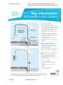
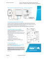


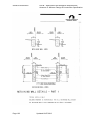
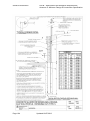
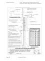

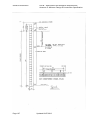
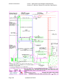
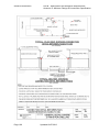
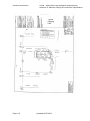

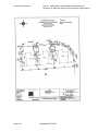
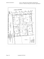


![1127117 - [PROJECT.TOC] - Performance Heating & Plumbing](http://vs1.manualzilla.com/store/data/005895106_1-55e9d6c83dbc31a8ba61d6bb401245cf-150x150.png)