1
SINAMICS S150
Converter Cabinet Units 75 kW to 1200 kW
Operating Instructions · 10/2008
SINAMICS
s
Preface
SINAMICS
SINAMICS S150
Drive converter cabinet units
Safety information
1
Device overview
2
Mechanical installation
3
Electrical installation
4
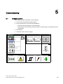
Commissioning
5
Operation
6
Setpoint channel and closedloop control
7
Output terminals
8
Functions, monitoring, and
protective functions
9
Operating Instructions
Diagnosis / faults and alarms
10
Maintenance and servicing
11
Technical specifications
12
Appendix
Control version V2.6 SP1
10/2008
A5E00288214A
A
Legal information
Warning notice system
This manual contains notices you have to observe in order to ensure your personal safety, as well as to prevent
damage to property. The notices referring to your personal safety are highlighted in the manual by a safety alert
symbol, notices referring only to property damage have no safety alert symbol. These notices shown below are
graded according to the degree of danger.
DANGER
indicates that death or severe personal injury will result if proper precautions are not taken.
WARNING
indicates that death or severe personal injury may result if proper precautions are not taken.
CAUTION
with a safety alert symbol, indicates that minor personal injury can result if proper precautions are not taken.
CAUTION
without a safety alert symbol, indicates that property damage can result if proper precautions are not taken.
NOTICE
indicates that an unintended result or situation can occur if the corresponding information is not taken into
account.
If more than one degree of danger is present, the warning notice representing the highest degree of danger will
be used. A notice warning of injury to persons with a safety alert symbol may also include a warning relating to
property damage.
Qualified Personnel
The device/system may only be set up and used in conjunction with this documentation. Commissioning and
operation of a device/system may only be performed by qualified personnel. Within the context of the safety notes
in this documentation qualified persons are defined as persons who are authorized to commission, ground and
label devices, systems and circuits in accordance with established safety practices and standards.
Proper use of Siemens products
Note the following:
WARNING
Siemens products may only be used for the applications described in the catalog and in the relevant technical
documentation. If products and components from other manufacturers are used, these must be recommended
or approved by Siemens. Proper transport, storage, installation, assembly, commissioning, operation and
maintenance are required to ensure that the products operate safely and without any problems. The permissible
ambient conditions must be adhered to. The information in the relevant documentation must be observed.
Trademarks
All names identified by ® are registered trademarks of the Siemens AG. The remaining trademarks in this
publication may be trademarks whose use by third parties for their own purposes could violate the rights of the
owner.
Disclaimer of Liability
We have reviewed the contents of this publication to ensure consistency with the hardware and software
described. Since variance cannot be precluded entirely, we cannot guarantee full consistency. However, the
information in this publication is reviewed regularly and any necessary corrections are included in subsequent
editions.
Siemens AG
Industry Sector
Postfach 48 48
90026 NÜRNBERG
GERMANY
A5E00288214A
Ⓟ 02/2009
Copyright © Siemens AG 2008.
Technical data subject to change
Preface
User documentation
WARNING
Before installing and commissioning the converter, make sure that you read all the safety
notes and warnings carefully, including the warning labels on the equipment itself. The
warning labels must always be legible. Missing or damaged labels must be replaced.
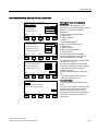
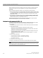
Structure of this documentation
The customer documentation comprises general and individual documentation.
The general documentation describes the topics that apply to all cabinet units:
● Operating Instructions
The Operating Instructions consist of the following sections:
– Device description
– Mechanical installation
– Electrical installation
– Commissioning guide
– Description of function
– Maintenance instructions
– Technical specifications
● Overview diagrams
These provide a general overview of the functionality of the cabinet units.
● Basic function diagrams
These provide an overview of the basic functions of the cabinet unit for simple
applications.
● List Manual
The List Manual consists of the following sections:
– Parameter list
– Function diagrams
– Fault / warning list
● Documentation for Drive Control Chart (DCC)
– Programming and Operating Manual: DCC Editor description
– Function Manual: Description of the standard DCC blocks
Drive converter cabinet units
Operating Instructions, 10/2008, A5E00288214A
5
Preface
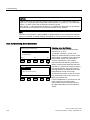
The individual documentation describes precisely one customized cabinet unit and contains
the following:
● Dimension drawing
The dimension drawing documents the dimensions of the ordered cabinet unit.
● Layout diagram
The layout diagram shows the components installed in the ordered cabinet unit.
● Circuit diagram
The circuit diagram shows the electrical components installed in the ordered cabinet unit,
their interconnections and the customer interfaces.
● Terminal diagram
The terminal diagram shows all the customer terminals in the ordered cabinet unit, and
the associated internal wiring in the cabinet unit. This diagram documents the line-side
target wiring.
● Spare parts list
The spare parts list contains all the available spare parts for the ordered cabinet unit.
● Additional operating instructions
The instructions for OEM components installed in the ordered cabinet unit are supplied as
OEM documentation.
Technical support
● Tel: +49 (0) 180 50 50 222
● Fax: +49 (0) 180 50 50 223
● Internet: http://www.siemens.de/automation/support-request
Note
Calls are subject to charge (e.g. € 0.14/min from fixed lines within Germany). Tariffs of other
phone providers may differ.
Spare parts
You will find spare parts on the Internet at:
http://support.automation.siemens.com/WW/view/en/16612315.
Internet address
Information about SINAMICS can be found on the Internet at the following address:
http://www.siemens.com/sinamics
6
Drive converter cabinet units
Operating Instructions, 10/2008, A5E00288214A
Table of contents
Preface ...................................................................................................................................................... 5
1
2
3
4
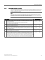
Safety information.................................................................................................................................... 15
1.1
Warnings ......................................................................................................................................15
1.2
Safety and operating instructions.................................................................................................16
1.3
Components that can be destroyed by electrostatic discharge (ESD) ........................................17
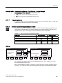
Device overview....................................................................................................................................... 21
2.1
Chapter content ...........................................................................................................................21
2.2
2.2.1
2.2.2
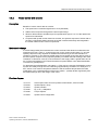
Applications, features, and design ...............................................................................................21
Applications..................................................................................................................................21
Features, quality, service .............................................................................................................22
2.3
Structure.......................................................................................................................................24
2.4
Wiring principle.............................................................................................................................26
2.5
Type plate ....................................................................................................................................27
Mechanical installation............................................................................................................................. 31
3.1
Chapter content ...........................................................................................................................31
3.2
Transportation and storage..........................................................................................................32
3.3
3.3.1
3.3.2
3.3.3
3.3.4
3.3.5
Installation ....................................................................................................................................34
Mechanical installation: checklist .................................................................................................35
Preparation...................................................................................................................................36
Installation ....................................................................................................................................37
Fitting additional canopies (option M21) or hoods (option M23, M43, M54) ...............................38
Line connection from above (option M13), motor connection from above (option M78) .............41
Electrical installation ................................................................................................................................ 43
4.1
Chapter content ...........................................................................................................................43
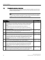
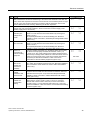
4.2
Checklist for electrical installation ................................................................................................44
4.3
Important safety precautions........................................................................................................49
4.4
Introduction to EMC .....................................................................................................................50
4.5
EMC-compliant design.................................................................................................................52
4.6
4.6.1
4.6.2
4.6.3
4.6.4
4.6.5
Power connections.......................................................................................................................54
Connection cross-sections and cable lengths .............................................................................54
Connecting the motor and power cables .....................................................................................55
Adjusting the fan voltage (-G1 -T10, -T1 -T10)............................................................................57
Adjusting the internal power supply (-A1-T10).............................................................................59
Removing the connection bracket for the interference-suppression capacitor with
operation from an ungrounded supply .........................................................................................60
4.7
External supply of the auxiliary supply from a secure line...........................................................61
Drive converter cabinet units
Operating Instructions, 10/2008, A5E00288214A
7
Table of contents
4.8
4.8.1
Signal connections ...................................................................................................................... 62
Customer terminal block (-A60) .................................................................................................. 62
4.9
4.9.1
4.9.2
4.9.3
4.9.4
4.9.5
4.9.6
4.9.7
4.9.8
4.9.9
4.9.10
4.9.11
4.9.11.1
4.9.12
4.9.13
4.9.14
4.9.15
4.9.16
4.9.17
4.9.17.1
4.9.17.2
4.9.17.3
4.9.18
4.9.18.1
4.9.18.2
4.9.18.3
4.9.19
4.9.19.1
4.9.19.2
4.9.19.3
4.9.20
Other connections ....................................................................................................................... 70
dv/dt filter plus Voltage Peak Limiter (option L10) ...................................................................... 70
Sine-wave filter (option L15) ....................................................................................................... 72
Connection for external auxiliary equipment (Option L19).......................................................... 74
Main switch incl. fuses or main circuit breaker (option L26) ....................................................... 75
EMERGENCY OFF pushbutton installed in the cabinet door (option L45) ................................ 77
Cabinet illumination with service socket (option L50) ................................................................. 78
Cabinet anti-condensation heating (option L55) ......................................................................... 78
EMERGENCY OFF category 0; 230 V AC or 24 V DC (option L57) .......................................... 79
EMERGENCY STOP category 1; 230 V AC (option L59) .......................................................... 81
EMERGENCY STOP category 1; 24 V DC (option L60) ............................................................ 82
25 kW braking unit (option L61/L64); 50 kW braking unit (option L62/L65)................................ 83
Installing the braking resistor ...................................................................................................... 83
Thermistor motor protection unit (option L83/L84)...................................................................... 89
PT100 evaluation unit (option L86) ............................................................................................. 89
Insulation monitor (option L87) ................................................................................................... 91
Communication Board Ethernet CBE20 (option G33) ................................................................ 93
CBC10 CAN Communication Board (option G20) ...................................................................... 95
SMC10 Sensor Module Cabinet-Mounted (option K46) ............................................................. 98
Description .................................................................................................................................. 98
Connection .................................................................................................................................. 99
Connection example ................................................................................................................. 100
SMC20 Sensor Module Cabinet-Mounted (option K48) ........................................................... 102
Description ................................................................................................................................ 102
Connection ................................................................................................................................ 103
Connection example ................................................................................................................. 104
SMC30 Sensor Module Cabinet-Mounted (option K50) ........................................................... 106
Description ................................................................................................................................ 106
Connection ................................................................................................................................ 111
Connection examples................................................................................................................ 113
Voltage Sensing Module for determining the actual motor speed and the phase angle
(option K51)............................................................................................................................... 114
Customer terminal block extension (option G61)...................................................................... 114
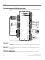
Terminal module for activation of "Safe Torque Off" and "Safe STOP 1" (option K82)............ 115
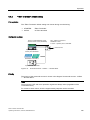
NAMUR terminal block (option B00) ......................................................................................... 116
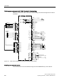
Electrically separate 24 V DC power supply for NAMUR (option B02)..................................... 118
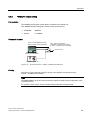
Outgoing section for external auxiliary equipment for NAMUR (option B03)............................ 118
4.9.21
4.9.22
4.9.23
4.9.24
4.9.25
5
8
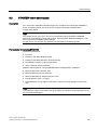
Commissioning ...................................................................................................................................... 119
5.1
Chapter content......................................................................................................................... 119
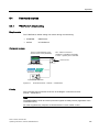
5.2
5.2.1
5.2.2
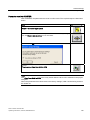
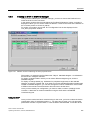
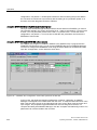
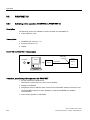
STARTER commissioning tool.................................................................................................. 121
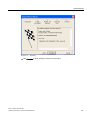
Installing STARTER .................................................................................................................. 122
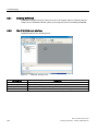
The STARTER user interface ................................................................................................... 122
5.3
5.3.1
5.3.2
5.3.3
5.3.4
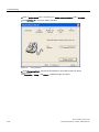
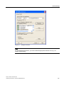
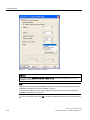
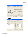
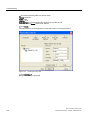
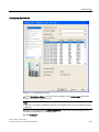
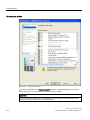
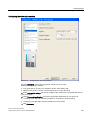
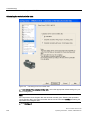
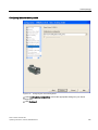
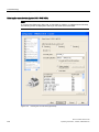
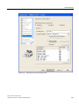
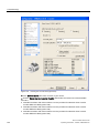
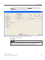
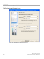
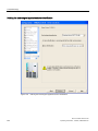
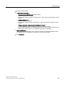
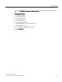
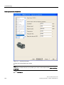
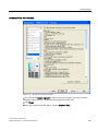
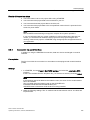
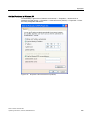
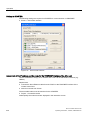
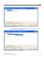
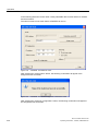
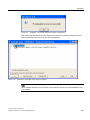
Procedure for commissioning via STARTER ............................................................................ 123
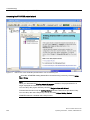
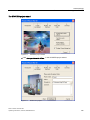
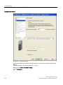
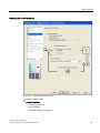
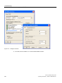
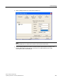
Creating a project...................................................................................................................... 123
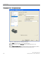
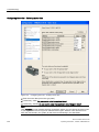
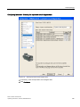
Configuring the drive unit .......................................................................................................... 132
Starting the drive project ........................................................................................................... 160
Connection via serial interface.................................................................................................. 161
5.4
The AOP30 operator panel ....................................................................................................... 164
Drive converter cabinet units
Operating Instructions, 10/2008, A5E00288214A
Table of contents
6
5.5
5.5.1
5.5.2
First commissioning with the AOP30 .........................................................................................165
First commissioning ...................................................................................................................165
Basic commissioning .................................................................................................................167
5.6
Status after commissioning........................................................................................................176
5.7
Commissioning an encoder with gear factor..............................................................................177
5.8
Parameter reset to factory settings ............................................................................................178
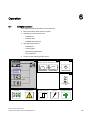
Operation............................................................................................................................................... 181
6.1
Chapter content .........................................................................................................................181
6.2
General information about command and setpoint sources ......................................................182
6.3
6.3.1
6.3.2
6.3.3
6.3.4
Basic information about the drive system ..................................................................................183
Parameters.................................................................................................................................183
Drive objects ..............................................................................................................................185
Data sets ....................................................................................................................................187
BICO technology: Interconnecting signals.................................................................................192
6.4
6.4.1
6.4.2
6.4.3
6.4.4
Command sources.....................................................................................................................197
"PROFIdrive" default setting ......................................................................................................197
"TM31 terminals" default setting ................................................................................................199
"NAMUR" default setting............................................................................................................201
"PROFIdrive NAMUR" default setting ........................................................................................203
6.5
6.5.1
6.5.2
6.5.3
Setpoint sources ........................................................................................................................205
Analog inputs .............................................................................................................................205
Motorized potentiometer ............................................................................................................207
Fixed speed setpoints ................................................................................................................209
6.6
6.6.1
6.6.2
6.6.3
6.6.4
6.6.5
6.6.5.1
6.6.5.2
6.6.6
PROFIBUS.................................................................................................................................210
PROFIBUS connection ..............................................................................................................210
Control via PROFIBUS ..............................................................................................................214
Monitoring: Telegram failure ......................................................................................................215
Telegrams and process data .....................................................................................................216
Structure of the telegrams..........................................................................................................218
Overview of control words and setpoints ...................................................................................219
Overview of status words and actual values..............................................................................220
Creating an S150 in SIMATIC Manager ....................................................................................221
6.7
6.7.1
6.7.2
6.7.3
6.7.4
6.7.5
6.7.5.1
6.7.5.2
6.7.5.3
6.7.5.4
6.7.5.5
6.7.6
6.7.7
6.7.7.1
6.7.7.2
6.7.7.3
6.7.7.4
6.7.7.5
Control via the operator panel....................................................................................................223
Operator panel (AOP30) overview and menu structure ............................................................223
Menu: Operation screen ............................................................................................................225
Menu: Parameterization.............................................................................................................225
Menu: Fault/alarm memory ........................................................................................................228
Menu: Commissioning / service .................................................................................................229
Drive commissioning..................................................................................................................229
Device commissioning ...............................................................................................................229
AOP30 settings ..........................................................................................................................229
Lists of signals for the operation screen ....................................................................................230
AOP30 diagnosis .......................................................................................................................234
Language/Sprache/Langue/Idioma/Lingua................................................................................235
Operation via the operator panel (LOCAL mode) ......................................................................235
LOCAL/REMOTE key ................................................................................................................236
ON key / OFF key ......................................................................................................................236
Switching between clockwise and counter-clockwise rotation...................................................237
Jog .............................................................................................................................................237
Increase setpoint / decrease setpoint ........................................................................................237
Drive converter cabinet units
Operating Instructions, 10/2008, A5E00288214A
9
Table of contents
7
8
9
10
6.7.7.6
6.7.7.7
6.7.7.8
6.7.8
6.7.9
6.7.10
AOP setpoint ............................................................................................................................. 238
Timeout monitoring ................................................................................................................... 239
Operator input inhibit / parameterization inhibit ........................................................................ 239
Faults and alarms...................................................................................................................... 241
Saving the parameters permanently ......................................................................................... 242
Parameterization errors............................................................................................................. 243
6.8
6.8.1
6.8.2
6.8.2.1
6.8.2.2
6.8.2.3
6.8.2.4
6.8.3
PROFINET IO ........................................................................................................................... 244
Activating online operation: STARTER via PROFINET IO ....................................................... 244
General information about PROFINET IO ................................................................................ 250
General information about PROFINET IO for SINAMICS......................................................... 250
Real-time (RT) and isochronous real-time (IRT) communication ............................................. 251
Addresses ................................................................................................................................. 252
Data transmission ..................................................................................................................... 254
Further information about communication via PROFINET IO................................................... 254
6.9
Engineering Software Drive Control Chart (DCC) .................................................................... 255
Setpoint channel and closed-loop control .............................................................................................. 257
7.1
Chapter content......................................................................................................................... 257
7.2
7.2.1
7.2.2
7.2.3
7.2.4
7.2.5
Setpoint channel ....................................................................................................................... 258
Setpoint addition ....................................................................................................................... 258
Direction of rotation changeover ............................................................................................... 259
Skip speeds and minimum speeds ........................................................................................... 260
Speed limitation......................................................................................................................... 261
Ramp-function generator .......................................................................................................... 262
7.3
7.3.1
7.3.2
V/f control .................................................................................................................................. 264
Voltage boost ............................................................................................................................ 267
Slip compensation..................................................................................................................... 270
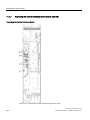
7.4
7.4.1
7.4.2
7.4.3
7.4.3.1
7.4.3.2
7.4.3.3
7.4.3.4
7.4.3.5
7.4.4
7.4.5
7.4.6
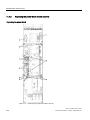
Vector speed/torque control with/without encoder.................................................................... 271
Vector control without encoder ................................................................................................. 272
Vector control with encoder....................................................................................................... 275
Speed controller ........................................................................................................................ 276
Examples of speed controller settings ...................................................................................... 278
Speed controller pre-control (integrated pre-control with balancing) ........................................ 279
Reference model....................................................................................................................... 282
Speed controller adaptation ...................................................................................................... 283
Droop Function.......................................................................................................................... 285
Closed-loop torque control ........................................................................................................ 286
Torque limiting........................................................................................................................... 289
Permanent-field synchronous motors ....................................................................................... 290
Output terminals .................................................................................................................................... 295
8.1
Chapter content......................................................................................................................... 295
8.2
8.2.1
Analog outputs .......................................................................................................................... 296
Lists of signals for the analog outputs....................................................................................... 297
8.3
Digital outputs ........................................................................................................................... 300
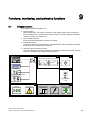
Functions, monitoring, and protective functions ..................................................................................... 303
9.1
Chapter content......................................................................................................................... 303
9.2
9.2.1
9.2.2
Active Infeed functions .............................................................................................................. 305
Line and DC link identification................................................................................................... 305
Harmonics controller ................................................................................................................. 306
Drive converter cabinet units
Operating Instructions, 10/2008, A5E00288214A
Table of contents
9.2.3
9.2.4
Variable power factor (reactive power compensation) ..............................................................307
Settings for the infeed (Active Infeed) under difficult line conditions .........................................308
9.3
9.3.1
9.3.1.1
9.3.1.2
9.3.2
9.3.3
9.3.4
9.3.5
9.3.6
9.3.6.1
9.3.6.2
9.3.6.3
9.3.7
9.3.7.1
9.3.7.2
9.3.7.3
9.3.7.4
9.3.8
9.3.9
9.3.9.1
9.3.9.2
9.3.10
9.3.11
9.3.12
9.3.13
9.3.14
Drive functions ...........................................................................................................................310
Motor identification and automatic speed controller optimization ..............................................310
Standstill measurement .............................................................................................................311
Rotating measurement and speed controller optimization ........................................................313
Efficiency optimization ...............................................................................................................316
Fast magnetization for induction motors....................................................................................317
Vdc control .................................................................................................................................318
Automatic restart function ..........................................................................................................322
Flying restart ..............................................................................................................................325
Flying restart without encoder....................................................................................................326
Flying restart with encoder.........................................................................................................327
Parameters.................................................................................................................................327
Motor changeover/selection.......................................................................................................328
Description .................................................................................................................................328
Example of changing over between two motors ........................................................................328
Function diagram .......................................................................................................................329
Parameters.................................................................................................................................330
Friction characteristic curve .......................................................................................................330
Increasing the output frequency.................................................................................................332
Increasing the pulse frequency ..................................................................................................333
Parameters.................................................................................................................................334
Runtime (operating hours counter) ............................................................................................335
Simulation operation ..................................................................................................................336
Direction reversal .......................................................................................................................337
Unit changeover.........................................................................................................................338
Derating behavior at increased pulse frequency .......................................................................339
9.4
9.4.1
9.4.2
9.4.2.1
9.4.2.2
9.4.2.3
9.4.2.4
9.4.2.5
9.4.3
9.4.4
9.4.5
9.4.5.1
9.4.5.2
9.4.5.3
9.4.5.4
9.4.6
9.4.6.1
9.4.6.2
9.4.6.3
9.4.6.4
9.4.6.5
9.4.6.6
9.4.6.7
9.4.6.8
Extended functions ....................................................................................................................342
Technology controller.................................................................................................................342
Bypass function..........................................................................................................................345
Bypass with synchronizer with degree of overlapping (p1260 = 1) ...........................................346
Bypass with synchronizer without degree of overlapping (p1260 = 2) ......................................348
Bypass without synchronizer (p1260 = 3)..................................................................................350
Function diagram .......................................................................................................................351
Parameters.................................................................................................................................352
Extended braking control ...........................................................................................................353
Extended monitoring functions...................................................................................................355
Closed-loop position control.......................................................................................................357
Actual position value preparation...............................................................................................358
Closed-loop position controller...................................................................................................367
Monitoring functions...................................................................................................................368
Measurement probe evaluation and reference mark search .....................................................370
Basic positioner..........................................................................................................................372
Mechanical system ....................................................................................................................374
Limitations ..................................................................................................................................376
Referencing................................................................................................................................381
Traversing blocks.......................................................................................................................389
Traversing to fixed stop..............................................................................................................395
Direct setpoint specification (MDI) .............................................................................................398
Jog .............................................................................................................................................401
Status signals.............................................................................................................................402
Drive converter cabinet units
Operating Instructions, 10/2008, A5E00288214A
11
Table of contents
9.5
9.5.1
9.5.2
9.5.3
9.5.4
9.5.5
10
11
12
Monitoring and protective functions .......................................................................................... 405
Protecting power components................................................................................................... 405
Thermal monitoring and overload responses............................................................................ 406
Blocking protection.................................................................................................................... 408
Stall protection (only for vector control) .................................................................................... 409
Thermal motor protection .......................................................................................................... 410
Diagnosis / faults and alarms................................................................................................................. 413
10.1
Chapter content......................................................................................................................... 413
10.2
10.2.1
10.2.2
10.2.3
Diagnosis................................................................................................................................... 414
Diagnostics via LEDs ................................................................................................................ 414
Diagnostics via parameters....................................................................................................... 421
Indicating and rectifying faults................................................................................................... 425
10.3
10.3.1
10.3.2
10.3.3
10.3.4
Overview of warnings and faults ............................................................................................... 426
"External alarm 1" ..................................................................................................................... 426
"External fault 1"........................................................................................................................ 427
"External fault 2"........................................................................................................................ 427
"External fault 3"........................................................................................................................ 427
10.4
10.4.1
Service and Support.................................................................................................................. 428
Spare parts................................................................................................................................ 429
Maintenance and servicing .................................................................................................................... 431
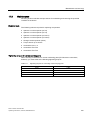
11.1
Chapter content......................................................................................................................... 431
11.2
11.2.1
Maintenance.............................................................................................................................. 432
Cleaning .................................................................................................................................... 432
11.3
11.3.1
11.3.2
Maintenance.............................................................................................................................. 433
Installation device...................................................................................................................... 434
Using crane lifting lugs to transport power blocks .................................................................... 435
11.4
11.4.1
11.4.2
11.4.3
11.4.4
11.4.5
11.4.6
11.4.7
11.4.8
11.4.9
11.4.10
11.4.11
11.4.12
11.4.13
11.4.14
11.4.15
11.4.16
11.4.17
11.4.18
11.4.19
11.4.20
11.4.21
11.4.22
Replacing components.............................................................................................................. 437
Replacing the filter mats............................................................................................................ 437
Replacing the power block (frame size FX) .............................................................................. 438
Replacing the power block (frame size GX).............................................................................. 440
Replacing the power block (frame size HX).............................................................................. 442
Replacing the power block (frame size JX)............................................................................... 446
Replacing the Control Interface Board (frame size FX) ............................................................ 448
Replacing the Control Interface Board (frame size GX) ........................................................... 450
Replacing the Control Interface Board (frame size HX)............................................................ 452
Replacing the Control Interface Board (frame size JX) ............................................................ 454
Replacing the fan (frame size FX) ............................................................................................ 456
Replacing the fan (frame size GX)............................................................................................ 458
Replacing the fan (frame size HX) ............................................................................................ 460
Replacing the fan (frame size JX)............................................................................................. 464
Replacing the fan in the Active Interface Module (frame size FI) ............................................. 466
Replacing the fan in the Active Interface Module (frame size GI)............................................. 468
Replacing the fan in the Active Interface Module (frame size HI)_S150 .................................. 470
Replacing the fan in the Active Interface Module (frame size JI).............................................. 472
Replacing the fan fuses (-A2 -F101/F102, -G1 -F10/F11, -T1 -F10/F11)................................. 474
Replacing the fuses for the auxiliary power supply (-A1 -F11 / -A1 -F12) ................................ 474
Replacing the main fuses.......................................................................................................... 474
Replacing the cabinet operator panel ....................................................................................... 475
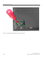
Replacing the Backup Battery for the Cabinet Operator Panel ................................................ 475
11.5
Forming the DC link capacitors................................................................................................. 477
Drive converter cabinet units
Operating Instructions, 10/2008, A5E00288214A
Table of contents
12
A
11.6
Messages after replacing DRIVE-CLiQ components.................................................................478
11.7
Upgrading the cabinet unit firmware ..........................................................................................479
11.8
Loading the new operator panel firmware from the PC. ............................................................480
Technical specifications......................................................................................................................... 481
12.1
Chapter content .........................................................................................................................481
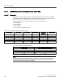
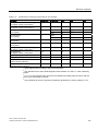
12.2
12.2.1
12.2.2
General technical specifications ................................................................................................482
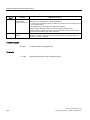
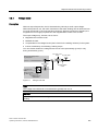
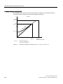
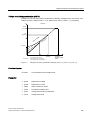
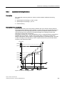
Derating data..............................................................................................................................483
Overload capability ....................................................................................................................487
12.3
12.3.1
12.3.2
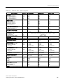
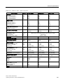
Technical specifications .............................................................................................................488
Cabinet unit version A, 380 V - 480 V 3 AC...............................................................................489
Cabinet unit version A, 500 V - 690 V 3 AC...............................................................................497
Appendix................................................................................................................................................ 509
A.1
List of abbreviations ...................................................................................................................509
A.2
Parameter macros .....................................................................................................................511
Index...................................................................................................................................................... 523
Drive converter cabinet units
Operating Instructions, 10/2008, A5E00288214A
13
Table of contents
14
Drive converter cabinet units
Operating Instructions, 10/2008, A5E00288214A
Safety information
1.1
1
Warnings
WARNING
Hazardous voltages are present when electrical equipment is in operation.
Severe personal injury or substantial material damage may result if these warnings are not
observed.
Only qualified personnel are permitted to work on or around the equipment.
This personnel must be thoroughly familiar with all warning and maintenance procedures
described in these operating instructions.
The successful and safe operation of this device is dependent on correct transport, proper
storage and installation, as well as careful operation and maintenance.
National safety guidelines must be observed.
DANGER
Five safety rules
When carrying out any kind of work on electrical devices, the "five safety rules" must
always be observed:
1. Disconnect the system.
2. Protect against reconnection.
3. Make sure that the equipment is de-energized.
4. Ground and short-circuit.
5. Cover or enclose adjacent components that are still live.
Certification
The following certificates:
● EC declaration of conformity
● Certificate of compliance with order
● EC manufacturer's declaration
can be found under "Safety and Operating Instructions" in the documentation folder.
Drive converter cabinet units
Operating Instructions, 10/2008, A5E00288214A
15
Safety information
1.2 Safety and operating instructions
1.2
Safety and operating instructions
DANGER
This equipment is used in industrial high-voltage installations. During operation, this
equipment contains rotating and live, bare parts. For this reason, they could cause severe
injury or significant material damage if the required covers are removed, if they are used or
operated incorrectly, or have not been properly maintained.
When the machines are used in non-industrial areas, the installation location must be
protected against unauthorized access (protective fencing, appropriate signs).
Prerequisites
Those responsible for protecting the plant must ensure the following:
● The basic planning work for the plant and the transport, assembly, installation,
commissioning, maintenance, and repair work is carried out by qualified personnel and/or
checked by experts responsible.
● The operating manual and machine documentation are always available.
● The technical specifications regarding the applicable installation, connection,
environmental, and operating conditions are always observed.
● The plant-specific assembly and safety guidelines are observed and personal protection
equipment is used.
● Unqualified personnel are forbidden from using these machines and working near them.
This operating manual is intended for qualified personnel and only contain information and
notes relating to the intended purpose of the machines.
The operating manual and machine documentation are written in different languages as
specified in the delivery contracts.
Note
We recommend engaging the support and services of your local Siemens service center for
all planning, installation, commissioning and maintenance work.
16
Drive converter cabinet units
Operating Instructions, 10/2008, A5E00288214A
Safety information
1.3 Components that can be destroyed by electrostatic discharge (ESD)
1.3
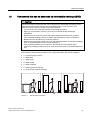
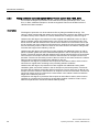
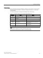
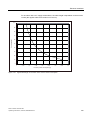
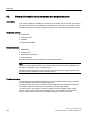
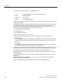
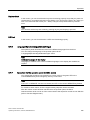
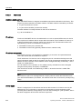
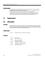
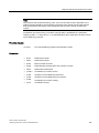
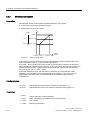
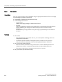
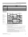
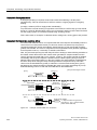
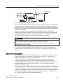
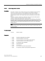
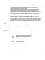
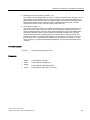
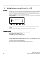
Components that can be destroyed by electrostatic discharge (ESD)
CAUTION
The board contains components that can be destroyed by electrostatic discharge. These
components can be easily destroyed if not handled properly. If you do have to use
electronic boards, however, please observe the following:
• You should only touch electronic boards if absolutely necessary.
• When you touch boards, however, your body must be electrically discharged
beforehand.
• Boards must not come into contact with highly insulating materials (such as plastic
parts, insulated desktops, articles of clothing manufactured from man-made fibers).
• Boards must only be placed on conductive surfaces.
• Boards and components should only be stored and transported in conductive packaging
(such as metalized plastic boxes or metal containers).
• If the packaging material is not conductive, the boards must be wrapped with a
conductive packaging material (such as conductive foam rubber or household aluminum
foil).
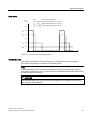
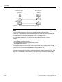
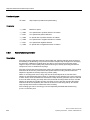
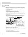
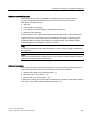
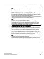
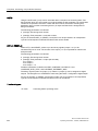
The necessary ESD protective measures are clearly illustrated in the following diagram:
● a = conductive floor surface
● b = ESD table
● c = ESD shoes
● d = ESD overall
● e = ESD wristband
● f = cabinet ground connection
● g = contact with conductive flooring
d
d
b
b
e
e
f
g
a
c
f
f
c
6LWWLQJ
Figure 1-1
d
a
6WDQGLQJ
f
f
g c
a
6WDQGLQJVLWWLQJ
ESD protective measures
Drive converter cabinet units
Operating Instructions, 10/2008, A5E00288214A
17
Safety information
1.3 Components that can be destroyed by electrostatic discharge (ESD)
Residual risks of power drive systems
When carrying out a risk assessment of the machine/plant in accordance with the EU
Machinery Directive, the machine manufacturer/plant operator must consider the following
residual risks associated with the control and drive components of a power drive system
(PDS).
1. Unintentional movements of driven machine components during commissioning,
operation, maintenance, and repairs caused by, for example:
– Hardware defects and/or software errors in the sensors, controllers, actuators, and
connection technology
– Response times of the controller and drive
– Operating and/or ambient conditions not within the scope of the specification
– Parameterization, programming, cabling, and installation errors
– Use of radio devices / cellular phones in the immediate vicinity of the controller
– External influences / damage
2. Exceptional temperatures as well as emissions of light, noise, particles, or gas caused by,
for example:
– Component malfunctions
– Software errors
– Operating and/or ambient conditions not within the scope of the specification
– External influences / damage
3. Hazardous shock voltages caused by, for example:
– Component malfunctions
– Influence of electrostatic charging
– Induction of voltages in moving motors
– Operating and/or ambient conditions not within the scope of the specification
– Condensation / conductive contamination
– External influences / damage
4. Electrical, magnetic and electromagnetic fields generated in operation that can pose a
risk to people with a pacemaker, implants or metal replacement joints, etc. if they are too
close.
5. Release of environmental pollutants or emissions as a result of improper operation of the
system and/or failure to dispose of components safely and correctly.
For more information about residual risks of the Power Drive System components, see the
relevant chapters in the technical user documentation.
18
Drive converter cabinet units
Operating Instructions, 10/2008, A5E00288214A
Safety information
1.3 Components that can be destroyed by electrostatic discharge (ESD)
WARNING
Electromagnetic fields "electro smog"
Electromagnetic fields are generated by the operation of electrical power engineering
installations such as transformers, converters or motors.
Electromagnetic fields can interfere with electronic devices, which could cause them to
malfunction. For example, the operation of heart pacemakers can be impaired, potentially
leading to damage to a person's health or even death. It is therefore forbidden for persons
with heart pacemakers to enter these areas.
The plant operator is responsible for taking appropriate measures (labels and hazard
warnings) to adequately protect operating personnel and others against any possible risk.
• Observe the relevant nationally applicable health and safety regulations. In Germany,
"electromagnetic fields" are subject to regulations BGV B11 and BGR B11 stipulated by
the German statutory industrial accident insurance institution.
• Display adequate hazard warning notices.
• Place barriers around hazardous areas.
• Take measures, e.g. using shields, to reduce electromagnetic fields at their source.
• Make sure that personnel are wearing the appropriate protective gear.
Drive converter cabinet units
Operating Instructions, 10/2008, A5E00288214A
19
Safety information
1.3 Components that can be destroyed by electrostatic discharge (ESD)
20
Drive converter cabinet units
Operating Instructions, 10/2008, A5E00288214A
Device overview
2.1
2
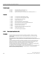
Chapter content
This chapter provides information on the following:
● Introduction to the cabinet units
● The main components and features of the cabinet unit
● The cabinet unit wiring
● Explanation of the type plate
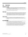
2.2
Applications, features, and design
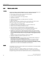
2.2.1
Applications
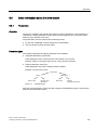
SINAMICS S150 drive converter cabinet units are used for variable-speed drives with
exacting demands regarding performance, and include drives with:
● High dynamic requirements
● Frequent braking cycles and high braking energy
● Four-quadrant operation
Typical applications for SINAMICS S150 include:
● Test bay drives
● Centrifuges
● Elevators and cranes
● Paper and rolling mill drives
● Cross cutters and shears
● Conveyor belts
● Presses
● Cable winches
Drive converter cabinet units
Operating Instructions, 10/2008, A5E00288214A
21
Device overview
2.2 Applications, features, and design
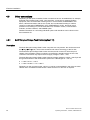
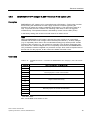
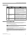
2.2.2
Features, quality, service
Features
The self-commutating, pulsed feed/feedback unit, which is based on IBGT technology and is
equipped with a clean-power filter, makes the minimum of demands on the line:
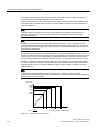
● The innovative clean-power filter minimizes line-side harmonics
● Power feedback (four-quadrant operation)
● Tolerant vis-à-vis fluctuations in the supply voltage
● Operation on weak lines
● Reactive power compensation is possible (inductive or capacitive)
● High drive dynamics
In addition, factors have been considered to ensure easy handling of the drive from the
planning and design phase through to operation. These factors include:
● Compact, modular, service-friendly design
● Straightforward planning and design thanks to the Sizer and Starter tools
● Ready to connect to facilitate the installation process
● Quick, menu-driven commissioning with no complex parameterization
● Clear and convenient operation via a user-friendly graphical operator panel with
measured values displayed in plain text or in a quasi-analog bar display.
● SINAMICS is an integral part of Totally Integrated Automation (TIA). The TIA concept
offers an optimized range of products for automation and drive technology. This concept
is characterized by planning / design, communication, and data management procedures
that are consistent throughout the product range. SINAMICS is fully integrated in the TIA
concept.
Separate S7/PCS7 blocks and faceplates for WinCC are available.
● Integration in SIMATIC H systems is possible via a Y link.
● Drive Control Chart (DCC)
Drive Control Chart (DCC) expands the facility for the simplest possible configuring of
technological functions for the SINAMICS drive system.
The block library encompasses a large selection of closed-loop, arithmetic and logic
function blocks, as well as more comprehensive open-loop and closed-loop control
functions. The user-friendly DCC editor enables easy graphical configuration and a clear
representation of control loop structures as well as a high degree of reusability of existing
diagrams. DCC is an add-on to the STARTER commissioning tool.
Quality
The SINAMICS S150 drive converter cabinet units are manufactured to meet high standards
of quality and exacting demands.
This results in a high level of reliability, availability, and functionality for our products.
The development, design, and manufacturing processes, as well as order processing and
the logistics supply center have been certified to DIN ISO 9001 by an independent authority.
22
Drive converter cabinet units
Operating Instructions, 10/2008, A5E00288214A
Device overview
2.2 Applications, features, and design
Service
Our worldwide sales and service network offers our customers consulting services tailored to
their needs, provides support with planning and design, and offers a range of training
courses.
For detailed contact information and the current link to our Internet pages, refer to chapter
"Diagnosis / faults and alarms", section "Service and Support".
Drive converter cabinet units
Operating Instructions, 10/2008, A5E00288214A
23
Device overview
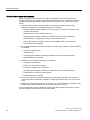
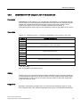
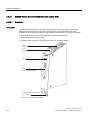
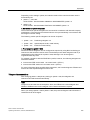
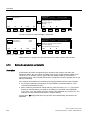
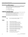
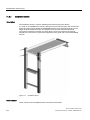
2.3 Structure
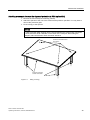
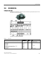
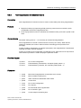
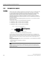
2.3
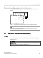
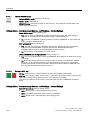
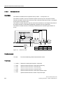
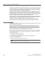
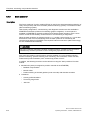
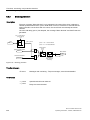
Structure
The SINAMICS S150 drive converter cabinet units are characterized by their compact,
modular, and service-friendly design.
Line and motor-side components as well as additional monitoring devices can be installed in
the converter cabinet units.
A wide range of electrical and mechanical components enable the drive system to be
optimized in line with prevailing requirements.
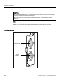
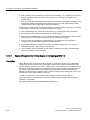
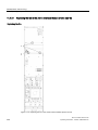
The cabinet unit comprises up to two cabinet panels with a total width of between 1400 mm
and 2800 mm, depending on the output.
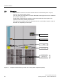
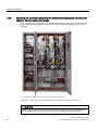
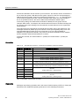
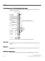
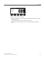
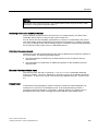
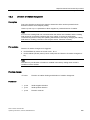
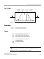
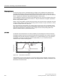
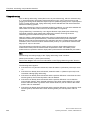
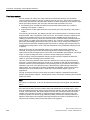
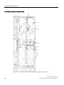
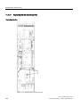
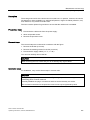
2SHUDWRUSDQHO
(PHUJHQF\VWRS
0DLQFLUFXLWEUHDNHU
4
'RRULQWHUORFN
9HQWLOLDWLRQJULOOHV
GHSHQGLQJRQ
GHJUHHRISURWHFWLRQ
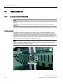
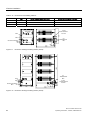
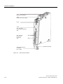
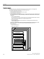
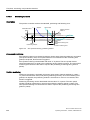
Figure 2-1
24
Example of a cabinet unit (e.g. 132 kW, 400 V 3 AC) (certain components optional)
Drive converter cabinet units
Operating Instructions, 10/2008, A5E00288214A
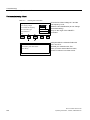
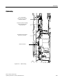
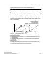
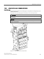
Device overview
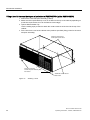
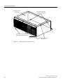
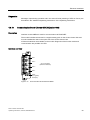
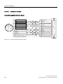
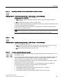
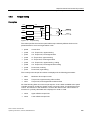
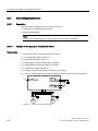
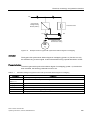
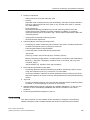
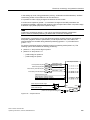
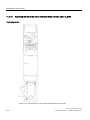
2.3 Structure
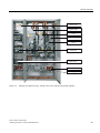
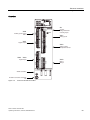
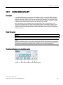
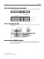
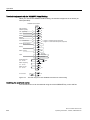
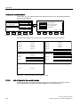
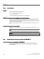
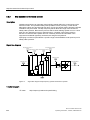
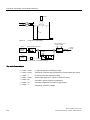
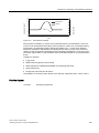
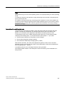
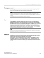
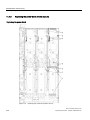
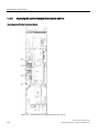
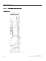
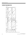
/LQH&RQQHFWLRQ
0RGXOH$
$FWLYH,QWHUIDFH
0RGXOH$
$FWLYH/LQH0RGXOH
*
0RWRU0RGXOH7
&8&RQWURO8QLW
$
/LQHFLUFXLWEUHDNHUZLWK
IXVHV4
&XVWRPHUWHUPLQDO
EORFN$
0RWRUFRQQHFWLRQ;
3RZHUVXSSO\;
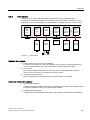
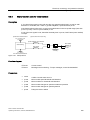
Figure 2-2
Example of a cabinet unit (e.g. 132 kW, 400 V 3 AC) (certain components optional)
Drive converter cabinet units
Operating Instructions, 10/2008, A5E00288214A
25
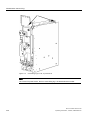
Device overview
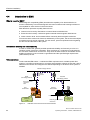
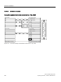
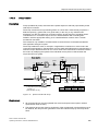
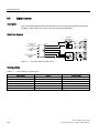
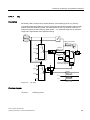
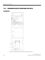
2.4 Wiring principle
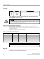
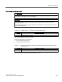
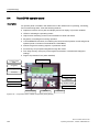
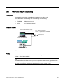
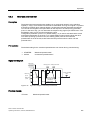
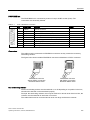
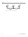
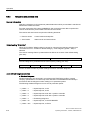
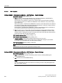
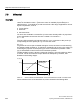
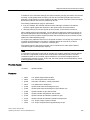
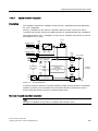
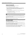
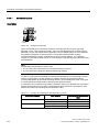
2.4
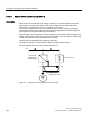
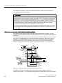
Wiring principle
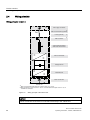
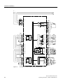
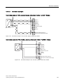
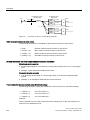
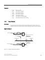
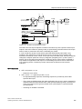
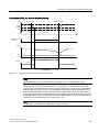
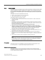
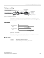
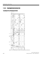
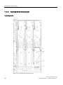
Wiring principle: version A
;
3(
/LQHVXSSO\FRQQHFWLRQ
0DLQFLUFXLWEUHDNHURSWLRQDO
)XVHVRSWLRQDO
0DLQFRQWDFWRU
$FWLYH,QWHUIDFH0RGXOH
:LWK&OHDQ3RZHU)LOWHU
ป
$FWLYH/LQH0RGXOH
9ROWDJH'&OLQN
ป
3(
0RWRU0RGXOH
0RWRUFRQQHFWLRQ
&DELQHWXQLW
0DLQFLUFXLWEUHDNHUZLWKIXVHVIRURXWSXWFXUUHQW$RQO\
0DLQFRQWDFWRUIRURXWSXWFXUUHQW$FLUFXLWEUHDNHUIRURXWSXWFXUUHQW!$
DYDLODEOHDVVWDQGDUG
Figure 2-3
Wiring principle of the cabinet unit
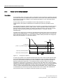
NOTICE
The PE connection at the motor must be fed back directly to the cabinet unit.
26
Drive converter cabinet units
Operating Instructions, 10/2008, A5E00288214A
Device overview
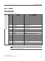
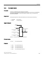
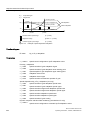
2.5 Type plate
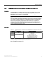
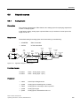
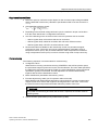
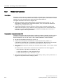
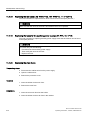
2.5
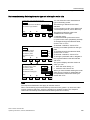
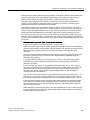
Type plate
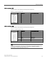
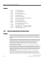
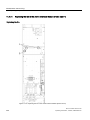
Specifications on the type plate
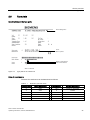
'HYLFHGHVLJQDWLRQ
/LVWRI
GHYLFHRSWLRQV
0RQWKRIPDQXIDFWXUH
<HDURIPDQXIDFWXUH
Figure 2-4
Type plate for the cabinet unit
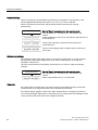
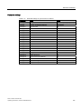
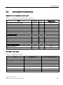
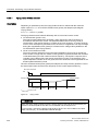
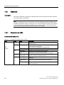
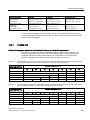
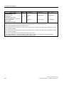
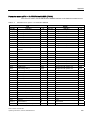
Date of manufacture
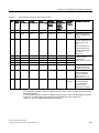
The date of manufacture can be determined as follows:
Table 2- 1
Production year and month
Letter/number
Year of manufacture
Letter/number
Month of manufacture
S
2004
1 to 9
January to September
T
2005
O
October
U
2006
N
November
D
December
V
2007
W
2008
X
2009
Drive converter cabinet units
Operating Instructions, 10/2008, A5E00288214A
27
Device overview
2.5 Type plate
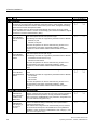
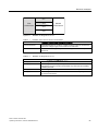
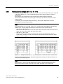
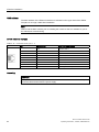
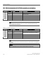
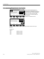
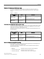
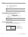
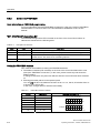
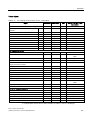
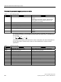
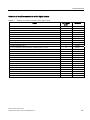
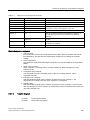
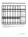
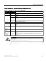
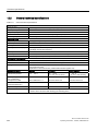
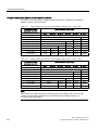
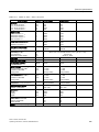
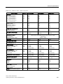
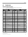
Type plate specifications (from type plate above)
Table 2- 2
Specifications on the type plate
Specification
Value
Input
3 AC
380 – 480 V
239 A
Three-phase connection
Rated input voltage
Rated input current
Output
3 AC
0 – 480 V
210 A
Three-phase connection
Rated output voltage
Rated output current
Temperature range
0 – 40 °C
Ambient temperature range within which the cabinet unit can operate under 100
% load
Degree of protection
IP20
Duty class
I
Cooling method
AF
Weight
28
Explanation
Degree of protection
I: Duty class I to EN 60146-1-1 = 100 % (continuously)
(with the specified current values, the cabinet unit can operate continuously
under 100 % load)
A: Cooling medium: air
F: circulation method: forced cooling, drive unit (fan) in the device
Weight of the cabinet unit
Drive converter cabinet units
Operating Instructions, 10/2008, A5E00288214A
Device overview
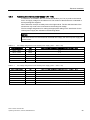
2.5 Type plate
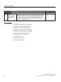
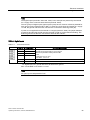
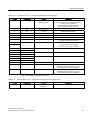
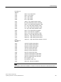
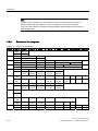
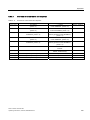
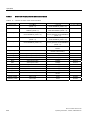
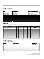
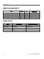
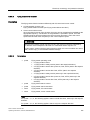
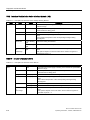
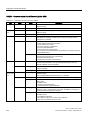
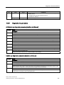
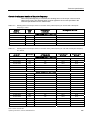
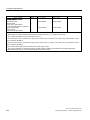
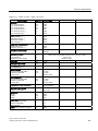
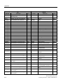
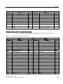
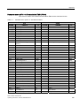
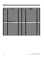
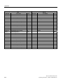
Explanation of the option short codes
Table 2- 3
Explanation of the option short codes
Input options
L00
Line filter for use in the first environment to EN 61800-3, category C2 (TN/TT systems)
L26
Main circuit breaker incl. fuses for output currents < 800 A
Output options
L08
Motor reactor
L10
dv/dt filter plus Voltage Peak Limiter
L15
Sine-wave filter (only for 380 V – 480 V 3 AC, max. 250 kW)
Input and output options
M70
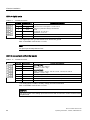
EMC shield bus
Motor protection and safety functions
L45
EMERGENCY OFF pushbutton installed in the cabinet door
L57
EMERGENCY OFF category 0, 230 V AC or 24 V DC
L59
EMERGENCY STOP category 1, 230 V AC
L60
EMERGENCY STOP category 1, 24 V AC
L83
Thermistor motor protection unit with PTB approval
L84
Thermistor motor protection unit with PTB approval
L86
PT100 evaluation unit
L87
Insulation monitoring
M60
Additional shock protection
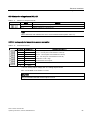
Increase in degree of protection
M21
Degree of protection IP21
M23
Degree of protection IP23
M43
Degree of protection IP43
M54
Degree of protection IP54
Mechanical options
M06
Base 100 mm high, RAL 7022
M07
Cable compartment 200 mm high, RAL 7035
M13
Line connection from above
M78
Motor connection from above
M90
Crane transport assembly (top-mounted)
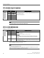
Other options
G20
CBC10 Communication Board
G33
CBE20 Communication Board
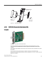
G61
Customer terminal block extension TM31
K46
Sensor Module Cabinet-Mounted SMC10
K48
Sensor Module Cabinet-Mounted SMC20
K50
Sensor Module Cabinet-Mounted SMC30
K51
VSM10 Voltage Sensing Module Cabinet-Mounted
K82
Terminal module for controlling the "Safe Torque Off" and "Safe Stop 1" safety functions
L19
Connection for external auxiliary equipment
Drive converter cabinet units
Operating Instructions, 10/2008, A5E00288214A
29
Device overview
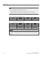
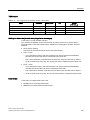
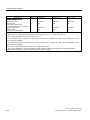
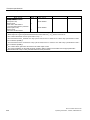
2.5 Type plate
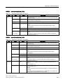
L50
Cabinet illumination with service socket
L55
Cabinet anti-condensation heating
L61
25 kW / 125 kW braking unit (380 V - 480 V, 660 V - 690 V)
L62
50 kW / 250 kW braking unit (380 V - 480 V, 660 V - 690 V)
L64
25 kW / 125 kW braking unit (500 V - 600 V)
L65
50 kW / 250 kW braking unit (500 V - 600 V)
Y09
Special paint finish for cabinet
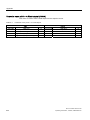
Documentation (standard: English / German)
D02
Customer documentation (circuit diagram, terminal diagram, layout diagram) in DXF format
D04
Customer documentation as hard copy
D14
Draft of customer documentation
D58
Documentation language: English / French
D60
Documentation language: English / Spanish
D80
Documentation language: English / Italian
Languages (standard: English / German)
T58
Rating plate data in English / French
T60
Rating plate data in English / Spanish
T80
Rating plate data in English / Italian
Industry-specific options (chemicals)
B00
NAMUR terminal block
B02
Separate 24 V power supply (PELV)
B03
Outgoing section for external auxiliary equipment (uncontrolled)
Options specific to the shipbuilding industry
M66
Marine version
E11
Individual certificate from Germanischer Lloyd (GL)
E21
Individual certificate from Lloyds Register (LR)
E31
Individual certificate from Bureau Veritas (BV)
E51
Individual certificate from Det Norske Veritas (DNV)
E61
Individual certificate from American Bureau of Shipping (ABS)
Converter acceptance inspection in presence of customer
F03
Visual acceptance
F71
Function test of the converter without motor connected
F75
Function test of the converter with test bay motor (no load)
F77
Insulation test on converter
F97
Customer-specific converter acceptance inspections (on request)
30
Drive converter cabinet units
Operating Instructions, 10/2008, A5E00288214A
Mechanical installation
3.1
3
Chapter content
This chapter provides information on the following:
● The conditions for transporting, storing, and installing the cabinet unit
● Preparing and installing the cabinet unit
Drive converter cabinet units
Operating Instructions, 10/2008, A5E00288214A
31
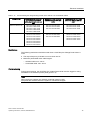
Mechanical installation
3.2 Transportation and storage
3.2
Transportation and storage
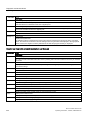
Transportation
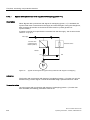
WARNING
The following must be taken into account when the devices are transported:
• The devices are heavy. Their center of gravity is displaced and they can be top heavy.
• Suitable hoisting gear operated by trained personnel is essential due to the weight of the
devices.
• The devices must only be transported in the upright position indicated. The devices
must not be transported upside down or horizontally.
• Serious injury or even death and substantial material damage can occur if the devices
are not lifted or transported properly.
Note
Information about shipping
• The devices are packaged by the manufacturer in accordance with the climatic conditions
and stress encountered during transit and in the recipient country.
• The notes on the packaging for transportation, storage, and proper handling must be
observed.
• For transportation using forklifts, the devices must be set down on a wooden pallet.
• When the devices are unpacked, they can be transported using the optional transport
eyebolts (option M90) or rails on the cabinet unit. The load must be distributed evenly.
Heavy blows or impacts must be avoided during transit and when the devices are being
set down, for example.
• Permissible ambient temperatures:
Ventilation: -25°C to +70°C, class 2K3 to IEC 60 721-3-2
Down to -40°C for max. 24 hours
Note
Notes regarding built-in line-side components
If built-in system-side components are to be installed on doors or side panels, you must take
the following points into account:
• The degree of protection (IP20, IP21, IP23, IP43, IP54) must not be reduced as a result.
• The electromagnetic compatibility of the cabinet unit must not be adversely affected.
• When control elements are installed on side or rear panels, these panels must be
grounded separately.
32
Drive converter cabinet units
Operating Instructions, 10/2008, A5E00288214A
Mechanical installation
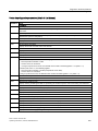
3.2 Transportation and storage
Note
Notes regarding damage in transit
• Carry out a thorough visual inspection of the device before accepting the delivery from
the shipping company.
• Check that you have received all the items specified on the delivery note.
• Notify the shipping company immediately of any missing components or damage.
• If you identify any hidden defects or damage, contact the shipping company immediately
and ask them to examine the device.
• If you fail to contact them immediately, you may lose your right to claim compensation for
the defects and damage.
• If necessary, you can request the support of your local Siemens office.
WARNING
Damage in transit indicates that the device has been subject to unreasonable stress. The
electrical safety of the device can no longer be ensured. It must not be connected until a
thorough high-voltage test has been carried out.
Non-observance can result in death, severe personal injury or substantial property damage.
Storage
The devices must be stored in clean, dry rooms. Temperatures between –25°C and +70°C
are permissible. Temperature variations greater than 20 K per hour are not permitted.
If the device is stored for a prolonged period once it has been unpacked, cover it or take
other appropriate measures to ensure that it does not become dirty and that it is protected
against environmental influences. Failure to take such measures will invalidate any claims
for damages under the terms of the warranty.
WARNING
The device should not be stored for more than two years. If the device is stored for more
than two years, its DC link capacitors must be reformed during commissioning.
The reforming procedure is described in "Maintenance and servicing".
Drive converter cabinet units
Operating Instructions, 10/2008, A5E00288214A
33
Mechanical installation
3.3 Installation
3.3
Installation
WARNING
To ensure that the devices operate safely and reliably, they must be properly installed and
commissioned by qualified personnel, taking into account the warnings provided in these
operating instructions.
In particular, the general and national installation and safety guidelines for high-voltage
installations (e.g. VDE – the Union of German Technical Engineers) as well as the
guidelines relating to the proper use of tools and personal protective equipment must be
observed.
Death, serious injury, or substantial material damage can result if these factors are not
taken into account.
34
Drive converter cabinet units
Operating Instructions, 10/2008, A5E00288214A
Mechanical installation
3.3 Installation
3.3.1
Mechanical installation: checklist
Use the following checklist to guide you through the mechanical installation procedure for the
cabinet unit. Read the safety information at the start of these Operating Instructions before
you start working on the device.
Note
Check the boxes accordingly in the right-hand column if the activity applies to the cabinet
unit in your scope of supply. In the same way, check the boxes once you have finished the
installation procedure to confirm that the activities are complete.
Item
1
Activity
Fulfilled/Complete
The ambient conditions must be permissible. See "Technical specifications, General
technical specifications".
The cabinet unit must be firmly attached to the fixing points provided.
The cooling air can flow unobstructed.
2
The minimum ceiling height (for unhindered air outlet) specified in the Operating
Instructions must be observed. The cooling air supply must be not be obstructed (see
"Mechanical installation/preparation").
3
Components that are supplied separately for transport reasons (canopy or hood) must
be fitted (see "Mechanical installation/Fitting additional canopies (option M21) or hoods
(option M23/M43/M54)").
4
The clearance around an open door (escape route) specified in the applicable accident
prevention guidelines must be observed.
5
With option M13/M78:
Choose the required metric screw connections or conduit thread connections on the
basis of the cable cross-section and drill the required holes in the blanking plates. When
the cable is fed in from above, ensure that enough room is available if the cable has to
be bent because of the cable feeder and cross-sections. The cable entries should be fed
in vertically to minimize transverse forces on the entries (see "Mechanical installation /
line connection from above (option M13), motor connection from above (option M78)").
Drive converter cabinet units
Operating Instructions, 10/2008, A5E00288214A
35
Mechanical installation
3.3 Installation
3.3.2
Preparation
On-site requirements
The cabinet units are designed for installation in closed, electrical operating areas in
compliance with EN 61800-5-1. A closed electrical operating area is a room or area
containing electrical equipment which can be accessed by trained personnel only. Access is
controlled by a door or other form of barricade which can be opened only by means of a key
or other tool. The room or area is also clearly signed with appropriate warning notices.
The operating areas must be dry and free of dust. The air supplied must not contain any
electrically conductive gas, vapors, or dust, which could impair operation. It may be
necessary to filter the air supplied to the installation room. If the air contains dust, filter mats
(option M54) can be installed in front of the ventilation grilles in the cabinet doors and also in
front of the hoods, if necessary. Option M54 offers additional protection against water
sprayed against the housing from any direction and corresponds to degree of protection
IP54.
The permissible values for climatic ambient conditions must be taken into account.
At temperatures > 40°C (104°F) and altitudes > 2000 m, the devices must be derated.
The basic version of the cabinet units complies with the IP20 degree of protection in
accordance with EN 60529.
The built-in units are installed in accordance with the dimension drawings supplied. The
clearance between the top of the cabinet unit and the ceiling is also specified on the
dimension drawings.
The cooling air for the power unit is drawn in from the front through the ventilation grilles in
the lower part of the cabinet doors. The warmed air is expelled through the perforated top
cover or the ventilation grilles in the top cover (with option M13/M23/M43/M54/M78). Cooling
air can also be supplied from below through raised floors or air ducts, for example. To allow
this, you have to create openings in the 3-section bottom plate.
According to EN 61800-3, the cabinet units are not suitable for use in low-voltage public
networks that supply residential buildings. High-frequency interference may occur if it is used
in this type of network.
Additional measures (e.g. line filter, option L00) can be fitted for use in the first environment
to EN 61800--3 category C2.
Unpacking the cabinets
Check the delivery against the delivery note to ensure that all the items have been delivered.
Check that the cabinet is intact.
The packaging material must be discarded in accordance with the applicable country-specific
guidelines and rules.
36
Drive converter cabinet units
Operating Instructions, 10/2008, A5E00288214A
Mechanical installation
3.3 Installation
Required tools
To install the connections, you will require:
● Spanner or socket spanner (w/f 10)
● Spanner or socket spanner (w/f 13)
● Spanner or socket spanner (w/f 16/17)
● Spanner or socket spanner (w/f 18/19)
● Hexagon-socket spanner (size 8)
● Torque wrench up to 50 Nm
● Screwdriver, size 2
● Screwdriver Torx T20
● Screwdriver Torx T30
3.3.3
Installation
Lifting the cabinet off the transport pallet
The applicable local guidelines regarding the transportation of the cabinet from the transport
palette to the installation location must be observed.
A crane transport assembly (option M90) can also be fitted on the top of the cabinet.
The fixing screws on the transport pallet can be removed from the pallet base without having
to raise the cabinet unit. The positions of the fixing screws are indicated by red markings on
the outside of the pallets.
Installation
Four holes for M12 screws are provided on each cabinet panel to secure the cabinet to the
ground. The fixing dimensions are specified on the dimension drawings enclosed.
Drive converter cabinet units
Operating Instructions, 10/2008, A5E00288214A
37
Mechanical installation
3.3 Installation
3.3.4
Fitting additional canopies (option M21) or hoods (option M23, M43, M54)
To increase the degree of protection of the cabinets from IP20 (standard) to IP21, IP23,
IP43, or IP54, additional canopies or hoods are supplied. These must be fitted once the
cabinets have been installed.
Description
The degree of protection can be increased to IP21 by fitting an additional canopy. The
canopy is flush-mounted with the cabinet unit and is fitted using spacers at a distance of 250
mm above the top of the cabinet. As a result, cabinets with a canopy are 250 mm higher.
Cabinet units with degree of protection IP23 are supplied with additional hoods, as well as
plastic ventilation grilles and braided plastic in the air inlet (doors) and outlet (hoods). The
hoods are flush with the cabinets at the side and front and have a recess at the rear so that
air can escape even if the cabinet is wall mounted. Air escapes from the front and back. The
hood is secured by means of the four holes for the crane hooks in the cabinet. Fitting hoods
increases the height of the cabinet by 400 mm.
Cabinet units with degree of protection IP43 are supplied with additional hoods, as well as
plastic ventilation grilles and close-meshed braided plastic in the air inlet (doors) and outlet
(hoods). The hoods are flush with the cabinets at the side and front and have a recess at the
rear so that air can escape even if the cabinet is wall mounted. Air escapes from the front
and back. The hood is secured by means of the four holes for the crane hooks in the cabinet.
Fitting hoods increases the height of the cabinets by 400 mm.
Compliance with degree of protection IP43 requires an intact filter medium, which must be
serviced on a regular basis according to the prevailing ambient conditions.
Cabinet units with degree of protection IP54 are supplied with additional hoods, plastic
ventilation grilles, and a filter medium in the air inlet (doors) and outlet (hoods). The hoods
are flush with the cabinets at the side and front and have a recess at the rear so that air can
escape even if the cabinet is wall mounted. Air escapes from the front and back. The hood is
secured by means of the four holes for the crane hooks in the cabinet. Hoods increase the
height of the cabinet by 400 mm.
Compliance with degree of protection IP54 requires an intact filter medium, which must be
replaced on a regular basis according to the prevailing ambient conditions. Filters can be
fitted and replaced from outside the cabinet relatively easily.
38
Drive converter cabinet units
Operating Instructions, 10/2008, A5E00288214A
Mechanical installation
3.3 Installation
Attaching a canopy to increase the degree of protection to IP21 (option M21)
1. Remove the crane transport assembly (if fitted).
2. Attach the spacers to the roof of the cabinet at the positions specified. You may have to
remove the protective grille.
3. Fit the canopy to the spacers.
NOTICE
In order to prevent water dripping into the spaces between the cabinet units connected
in series, there are "drain channels" on the sides of the canopies. When fitting the
canopies, make sure that the "drain channels" interlock.
,QVHUWWKHHQFORVHGVFUHZV
IURPDERYH
,QVHUWWKHHQFORVHG
VFUHZVIURPEHORZ
Figure 3-1
Fitting a canopy
Drive converter cabinet units
Operating Instructions, 10/2008, A5E00288214A
39
Mechanical installation
3.3 Installation
Fitting a hood to increase the degree of protection to IP23/IP43/IP54 (option M23/M43/M54)
1. Remove the crane transport assembly (if fitted).
2. Make sure that a perforated top cover is not fitted on the top of the cabinet (depending on
production requirements, this can be fitted at a later stage).
3. Options M43 and M54 only:
Use the sealing tape provided to attach the contact surfaces of the hood to the top of the
cabinet.
4. Fit the hood to the roof of the cabinet at the positions specified (fixing points for the crane
transport assembly).
,QVHUWWKHRULJLQDOKRRG
VFUHZV0IURPDERYH
,QVHUWWKHHQFORVHG
VFUHZVDQGSODLQZDVKHUV0
IURPEHORZ
$GGLWLRQDOVFUHZVKHUHIRU
ZLGHKRRGV
Figure 3-2
40
Attaching a hood
Drive converter cabinet units
Operating Instructions, 10/2008, A5E00288214A
Mechanical installation
3.3 Installation
3.3.5
Line connection from above (option M13), motor connection from above (option
M78)
Description
With options M13 and M78, the cabinet unit is equipped with an additional hood. The
connection straps for the power cables, the clamping bar for mechanically securing the
cables, an EMC shield bus, and a PE busbar are located within the hood.
The hood adds an extra 405 mm to the cabinet height. The busbars for connection from
above are fully mounted when the system is delivered. For transport reasons, the hoods are
delivered separately and must be mounted on site. With options M23, M43 and M54, plastic
ventilation grilles and filter mats are also supplied.
A 5 mm aluminum mounting plate (with no holes) is fitted in the roof of the cover for feeding
in the cables. Depending on the number of cables and the cross-sections used, holes for
attaching cable glands for feeding in the cables must be drilled in this mounting plate on site.
Note
The control cables and optional brake resistors are connected as before from below.
Attaching the Hood
1. Remove the crane transport assembly (if fitted).
2. Options M43 and M54 only:
Use the sealing tape provided to attach the contact surfaces of the hood to the top of the
cabinet.
3. Fit the hood to the roof of the cabinet at the positions specified (fixing points for the crane
transport assembly).
4. To secure the power cables, remove the front panel of the hood.
Drive converter cabinet units
Operating Instructions, 10/2008, A5E00288214A
41
Mechanical installation
3.3 Installation
0RXQWLQJSODWHIRU
FDEOHHQWU\
,QVHUWWKHRULJLQDOKRRG
VFUHZV0IURPDERYH
,QVHUWWKHHQFORVHGVFUHZVDQG
SODLQZDVKHUV0IURPEHORZ
$GGLWLRQDOVFUHZVKHUHIRU
ZLGHKRRGV
Figure 3-3
42
Attaching the hood with M13 / M78
Drive converter cabinet units
Operating Instructions, 10/2008, A5E00288214A
Electrical installation
4.1
4
Chapter content
This chapter provides information on the following:
● Establishing the electrical connections for the cabinet unit
● Adjusting the fan voltage and the internal power supply to local conditions (supply
voltage)
● The customer terminal block and its interfaces
● The interfaces for additional options
Drive converter cabinet units
Operating Instructions, 10/2008, A5E00288214A
43
Electrical installation
4.2 Checklist for electrical installation
4.2
Checklist for electrical installation
Use the following checklist to guide you through the electrical installation procedure for the
cabinet unit. Read the safety information at the start of these Operating Instructions before
you start working on the device.
Note
Check the boxes accordingly in the right-hand column if the activity applies to the cabinet
unit in your scope of supply. In the same way, check the boxes once you have finished the
installation procedure to confirm that the activities are complete.
Item
Activity
Fulfilled/Complete
Power connections
1
The line-side and motor-side power cables must be dimensioned and routed in accordance
with the ambient and routing conditions. The maximum permissible cable lengths between
the converter and motor must be observed depending on the type of cable used (see
"Electrical installation / Power connections / Connection cross-sections and cable
lengths").
The PE ground at the motor must be fed back directly to the cabinet unit.
The cables must be properly connected with a torque of 50 Nm to the cabinet unit
terminals. The cables for the motor and low-voltage switchgear must also be connected
with the required torques.
44
2
The cables between the low-voltage switchgear and the cabinet unit must be protected
with line fuses to provide adequate conductor protection (VDE 636, Part 10). See
"Technical specifications" for the appropriate fuses.
3
For strain relief, the cables must be clamped on the cable propping bar (C-type mounting
bar).
4
When EMC-shielded cables are used, screwed glands that connect the shield to ground
with the greatest possible surface area must be provided on the motor terminal box. On
the cabinet, the cables must be grounded with the clips supplied with the EMC shield bus
with the greatest possible surface area (shield bus supplied with option L00 or can be
ordered separately with option M70 – see "Electrical installation / EMC-compliant
installation").
5
The cable shields must be properly applied and the cabinet properly grounded at the
appropriate points (see "Electrical installation / EMC-compliant installation").
6
The voltage of the fan transformers in the Active Line Module (-G1 -T10) and in the Motor
Module (-T1 -T10) and in the internal power supply (-A1-T10) must be set. Larger cabinet
units have 2 fan transformers each in the Active Line Module and in the Motor Module
(-G1-T10/-T20) and (-A1-T10/-T20), which must be set jointly (see section "Electrical
installation / Power connections / Adjusting the fan voltage (-G1-T10, -T1-T10)" and
"Electrical installation / Power connections / Adjusting the internal power supply
(-A1 -T10)").
7
Before the cabinet is operated from an ungrounded supply/IT system, the connection
bracket for the interference suppression capacitor on the Active Interface Module (-A2)
must be removed (see "Electrical installation / Removing the connection bracket for the
interference suppression capacitor with operation from an ungrounded supply").
Drive converter cabinet units
Operating Instructions, 10/2008, A5E00288214A
Electrical installation
4.2 Checklist for electrical installation
Item
Activity
Fulfilled/Complete
8
The type plate can be used to ascertain the date of manufacture. If the period from the
date of manufacture to initial commissioning or the cabinet unit downtime is less than two
years, the DC link capacitors do not have to be re-formed. If the downtime period is longer
than two years, they must be reformed in accordance with the description found in the
section "Maintenance and servicing / Reforming the DC link capacitors".
9
With an external auxiliary supply, the cable for the 230 V AC supply must be connected to
terminal -X40 (see "Electrical installation / Power connections / External supply of the
auxiliary supply from a secure line").
10
Option L10
dv/dt filter plus
Voltage Peak
Limiter
11
Option L15
Sine-wave filter
12
Option L19
Connection for
external auxiliary
equipment
13
Option L26
Main circuit
breaker (incl.
fuses/circuit
breakers)
14
Option L50
Cabinet
illumination with
service socket
15
Option L55
Cabinet anticondensation
heating
During commissioning, the filter must be selected via STARTER or
AOP30. You are advised to check the selection by ensuring that
p0230 is set to 2.
The required parameters are set automatically (see "Electrical
installation / Other connections / dv/dt filter plus Voltage Peak Limiter
(option L10)").
During commissioning, the filter must be selected via STARTER or
AOP30. You are advised to check the selection by ensuring that
p0230 is set to 3.
The required parameters are set automatically (see "Electrical
installation / Other connections / Sine-wave filter (option L15)").
To supply auxiliary equipment (e.g. separately-driven fan for motor),
the drive must be properly connected to terminals -X155:1 (L1)
to -X155:3 (L3). The supply voltage of the auxiliary equipment must
match the input voltage of the cabinet unit. The load current must not
exceed 10 A and must be set at -Q155 in accordance with the load
connected (see "Electrical installation / Other connections /
Connection for external auxiliary equipment (option L19)").
Set value:
_________________
In equipment with main circuit breaker, the release current must be
set to match the installation requirements (see "Electrical Installation /
Other connections / Main switch incl. fuses or main circuit breaker
(option L26)").
The 230 V auxiliary supply for the cabinet illumination with an
integrated service socket must be connected to terminal -X390 and
protected with a fuse (max. 10 A) on the line side (see "Electrical
installation / Other connections / Cabinet illumination with service
socket (option L50)").
The 230 V auxiliary supply for the anti-condensation heating for the
cabinet (230 V / 50 Hz, 100 W / or 230 V / 50 Hz 2 x 100 W for
cabinets with a width of 800 to 1200 mm) must be connected to
terminals -X240: 1 to 3 and protected with fuses (max. 16 A) (see
"Electrical installation / Other connections / Anti-condensation heating
for cabinet (option L55)").
Drive converter cabinet units
Operating Instructions, 10/2008, A5E00288214A
45
Electrical installation
4.2 Checklist for electrical installation
Item
Activity
Fulfilled/Complete
Signal connections
16
Cabinet unit operation by higher-level controller / control room. The control cables must be
connected in accordance with the interface assignment and the shield applied. Taking into
account electrical interference and the distance from power cables, the digital and analog
signals must be routed with separate cables.
When the analog inputs on the customer terminal block are used as current or voltage
inputs, selectors S5.0 and S5.1 must be set accordingly (see "Electrical installation / Signal
connections / Customer terminal block (-A60)").
17
Option K46
Sensor Module
Cabinet-Mounted
SMC10
The SMC10 encoder module is used to simultaneously record the
motor actual speed and the rotor position angle.
The following encoders are supported by the SMC10 Sensor Module:
• Resolver, 2 pole
• Resolver, multi-pole.
The motor temperature can also be detected using KTY84-130 or
PTC thermistors (see section "Electrical installation / Other
connections / Sensor Module Cabinet-Mounted SMC10 (Option
K46)").
18
Option K48
Sensor Module
Cabinet-Mounted
SMC20
The SMC20 encoder module is used to simultaneously record the
motor actual speed and the path angle.
The following encoders are supported by the SMC20 Sensor Module:
• Incremental encoder sin/cos 1Vpp
• Absolute encoder EnDat
The motor temperature can also be detected using KTY84-130 or
PTC thermistors (see section "Electrical installation / Other
connections / Sensor Module Cabinet-Mounted SMC20 (Option
K48)").
19
Option K50
Sensor Module
Cabinet-Mounted
SMC30
The SMC30 Sensor Module is used for determining the actual motor
speed.
The following encoders are supported by the SMC30 Sensor Module:
• TTL encoder
• HTL encoder
• SSI encoder
The motor temperature can also be detected using KTY84-130 or
PTC thermistors (see section "Electrical installation / Other
connections / Sensor Module Cabinet-Mounted SMC30 (Option
K50)").
Connecting protection and monitoring devices
20
Option L45
EMERGENCY
OFF pushbutton
installed in the
cabinet door
21
Option L57
EMERGENCY
OFF category 0,
230 V AC or
24 V DC
46
The contacts for the EMERGENCY OFF pushbutton are available at
terminal -X120 and can be picked off so that they can be integrated in
a higher-level line-side protection concept ("Electrical installation /
Other connections / EMERGENCY OFF pushbutton, integrated in the
door of the cabinet unit (option L45)").
EMERGENCY OFF category 0 stops the drive in an uncontrolled
manner. No additional wiring is necessary when implemented in
conjunction with option L45.
If the cabinet unit is integrated in an external safety circuit, however,
the contact must be looped in via terminal block -X120 ("Electrical
installation / Other connections / EMERGENCY OFF category 0, 230
V AC / 24 V DC (option L57)").
Drive converter cabinet units
Operating Instructions, 10/2008, A5E00288214A
Electrical installation
4.2 Checklist for electrical installation
Item
22
Activity
Option L59
EMERGENCY
STOP category 1,
230 V AC
23
Option L60
EMERGENCY
STOP category 1,
24 V AC
24
Option
L61/L62/L64/L65
25 kW/125 kW
50 kW/250 kW
braking unit
25
Option L83
Thermistor motor
protection device
(alarm)
26
Option L84
Thermistor motor
protection device
(shutdown)
27
Option L86
PT100 evaluation
unit
28
Option L87
Insulation
monitoring
Fulfilled/Complete
EMERGENCY STOP category 1 stops the drive in a controlled
manner. No additional wiring is necessary when implemented in
conjunction with option L45.
If the cabinet unit is integrated in an external safety circuit, however,
the contact must be looped in via terminal block -X120. The timer
relay -K121 must be adapted to match system requirements (see
"Electrical installation / EMERGENCY STOP category 1, 230 V AC
(option L59)").
EMERGENCY STOP category 1 stops the drive in a controlled
manner. No additional wiring is necessary when implemented in
conjunction with option L45.
If the cabinet unit is integrated in an external safety circuit, however,
the contact must be looped in via terminal block -X120. The timer
relay at -K120 must be adapted to match system requirements (see
"Electrical installation / Other connections / EMERGENCY STOP
category 1, 24 V AC (option L60)").
The connecting cables and ground for the braking resistor must be
connected to terminal block –X5: 1/2. A connection must be
established between the braking resistor thermostatic switch and
customer terminal block –A60. When commissioning via AOP30, the
settings for evaluating "external fault 3" must be made. The settings
for evaluating the thermostatic switch as "external fault 2" must be
made (see "Electrical installation / Other connections / Braking unit
25 kW / 125 kW (option L61 / L64); braking unit 50 kW / 250 kW
(option L62 / L65)").
The PTC thermistor sensors (PTC resistor type A) must be connected
to the thermistor motor protection unit -F127 at terminals T1 and T2
for alarms (see "Electrical installation / Other connections /
Thermistor motor protection device (option L83/L84)").
The PTC thermistor sensors (PTC resistor type A) must be connected
to the thermistor motor protection unit -F125 at terminals T1 and T2
for shutdown (see "Electrical installation / Other connections /
Thermistor motor protection device (option L83/L84)").
The resistor thermometers must be connected to evaluation
unit -B140 for the PT100 evaluation. A two-wire or three-wire system
can be used here to connect the PT100 sensors. The sensors are
divided into two groups (see "Electrical installation / Other
connections / PT100 evaluation unit (option L86)"). This must be
taken into account for the evaluation (factory setting).
The insulation monitor can only be operated from an insulated
network. Only one insulation monitor can be used in an electricallyconnected network. For line-side control, the signaling relays must be
connected accordingly or, with individual drives (the cabinet unit is
fed via a converter transformer assigned to the cabinet unit),
integrated in the cabinet unit alarm train (see "Electrical installation /
Other connections / Insulation monitoring (option L87)").
Point 7 must also be taken into account:
"Before the cabinet is operated from an ungrounded supply/IT
system, the connection bracket for the basic interference suppression
device must be removed (see "Electrical installation / Removing the
connection bracket for the interference suppression capacitor with
operation from an ungrounded supply")".
Drive converter cabinet units
Operating Instructions, 10/2008, A5E00288214A
47
Electrical installation
4.2 Checklist for electrical installation
Item
Activity
Fulfilled/Complete
Safety Integrated
29
Option K82
"Safe Torque Off"
and "Safe Stop 1"
safety functions
The terminal block -X41 must be connected line-side, the safety
functions must be activated prior to use via parameter assignment, in
addition an acceptance test must be performed and an acceptance
log must be created (see section "Electrical installation / Other
connections / Terminal module for activating "Safe Torque Off" and
"Safe Stop 1" (option K82)").
Required tools
To install the connections, you will require:
● Spanner or socket spanner (w/f 10)
● Spanner or socket spanner (w/f 13)
● Spanner or socket spanner (w/f 16/17)
● Spanner or socket spanner (w/f 18/19)
● Hexagon-socket spanner (size 8)
● Torque wrench up to 50 Nm
● Screwdriver, size 2
● Screwdriver Torx T20
● Screwdriver Torx T30
48
Drive converter cabinet units
Operating Instructions, 10/2008, A5E00288214A
Electrical installation
4.3 Important safety precautions
4.3
Important safety precautions
WARNING
The cabinet units are operated with high voltages.
All connection procedures must be carried out when the cabinet is de-energized.
All work on the device must be carried out by trained personnel only.
Non-observance of these warning notices can result in death, severe personal injury or
substantial property damage.
Work on an open device must be carried out with extreme caution because external supply
voltages may be present. The power and control terminals may be live even when the
motor is not running.
Dangerously high voltage levels are still present in the device up to five minutes after it has
been disconnected due to the DC link capacitors. For this reason, the unit should not be
opened until a reasonable period of time has elapsed.
Reforming the DC link capacitors:
The storage period should not exceed two years. If the device is stored for more than two
years, its DC link capacitors must be reformed during commissioning.
The reforming procedure is described in "Maintenance and servicing".
The operator is responsible for ensuring that the motor, converter, and other devices are
installed and connected in accordance with recognized engineering practice in the country
of installation and in compliance with applicable regional regulations. Special attention
should be paid to cable dimensioning, fuses, grounding, shutdown, disconnection, and
overcurrent protection.
If an item of protective gear trips in a branch circuit, a fault current may have been
disconnected. To reduce the risk of fire or an electric shock, the current-conducting parts
and other components in the cabinet unit should be inspected and damaged parts replaced.
When an item of protective gear trips, the cause of the trip must be identified and rectified.
Note
Standard cabinet units are equipped with touch protection to BGV A3 in accordance with DIN
57 106, Part 100/VDE 0106, Part 100 (Germany).
The version with option M60 features additional protective covers that offer a higher level of
touch protection for current-conducting parts when the cabinet doors are open.
These protective covers may have to be removed during installation and connection
procedures. Once work has been completed, the protective covers must be properly refitted.
Note
On ungrounded systems and systems with a grounded phase conductor and a line voltage
>600 VAC, measures must be taken on the line side to limit overvoltages to overvoltage
category II in accordance with IEC 60664-1.
CAUTION
Only original DRIVE-CLiQ cables may be used for wiring the DRIVE-CLiQ nodes.
Drive converter cabinet units
Operating Instructions, 10/2008, A5E00288214A
49
Electrical installation
4.4 Introduction to EMC
4.4
Introduction to EMC
What is meant by EMC?
Electromagnetic compatibility (EMC) describes the capability of an electrical device to
function satisfactorily in an electromagnetic environment without itself causing interference
unacceptable for other devices in the environment.
EMC therefore represents a quality feature for the
● Internal noise immunity: Resistance to internal electrical disturbances
● External noise immunity: resistance against external electromagnetic disturbances
● Noise emission level: environmental effects caused by electromagnetic emissions
To ensure that the cabinet unit functions satisfactorily in the system, the environment subject
to interference must not be neglected. For this reason, special requirements exist regarding
the structure and the EMC of the system.
Operational reliability and noise immunity
In order to achieve the greatest possible operational reliability and immunity to noise of a
complete system (converter, automation, drive machines etc.), measures must be taken by
the converter manufacturer and the user. Only when all these measures are fulfilled can the
faultless functioning of the converter be guaranteed and the specified legal requirements
(2004/108/EC) be met.
Noise emissions
Product standard EN 61800 – 3 outlines the EMC requirements for variable-speed drive
systems. It specifies requirements for converters with operating voltages of less than 1000 V.
Different environments and categories are defined depending on where the drive system is
installed.
0HGLXPYROWDJHQHWZRUN
3XEOLF
ORZYROWDJHQHWZRUN
'LVWULEXWLRQ
RIFRQGXFWHG
IDXOWV
,QGXVWULDO
ORZYROWDJHQHWZRUN
0HDVXULQJSRLQWIRU
FRQGXFWHG
IDXOWV
)LUVW
HQYLURQPHQW
6HFRQG
HQYLURQPHQW
/LPLWRIIDFLOLW\
P
(TXLSPHQW
DIIHFWHGE\
IDXOWV
Figure 4-1
50
0HDVXULQJSRLQWIRUHPLWWHG
LQWHUIHUHQFH
'ULYH
LQWHUIHUHQFH
VRXUFH
Definition of the first and second environments
Drive converter cabinet units
Operating Instructions, 10/2008, A5E00288214A
Electrical installation
4.4 Introduction to EMC
&
)LUVW
HQYLURQPHQW
&
&
6HFRQG
HQYLURQPHQW
&
Figure 4-2
Definition of categories C1 to C4
Table 4- 1
Definition of the first and second environments
Definition of the first and second environments
First environment
Residential buildings or locations at which the drive system is connected to
a public low-voltage supply network without a transformer.
Second environment
Industrial locations supplied by a medium-voltage network via a separate
transformer.
Table 4- 2
Definition of categories C1 to C4
Definition of categories C1 to C4
Category C1
Rated voltage <1000 V; unrestricted use in the first environment.
Category C2
Rated voltage for stationary drive systems <1000 V; for use in the second
environment. For use in the first environment only when sold and installed
by skilled personnel.
Category C3
Rated voltage <1000 V; use in the second environment only.
Category C4
Rated voltage ≥1000 V or for rated currents ≥ 400 A in complex systems in
the second environment.
Drive converter cabinet units
Operating Instructions, 10/2008, A5E00288214A
51
Electrical installation
4.5 EMC-compliant design
4.5
EMC-compliant design
The following section provides some basic information and guidelines that will help you
comply with the EMC and CE guidelines.
cabinet assembly
● Connect painted or anodized metal components using toothed self-locking screws or
remove the insulating layer.
● Use unpainted, de-oiled mounting plates.
● Establish a central connection between ground and the protective conductor system
(ground).
Shield gaps
● Bridge shield gaps (at terminals, circuit-breakers, contactors, and so on) with minimum
impedance and the greatest possible surface area.
Using large cross-sections
● Use underground and grounding cables with large cross-sections or, better still, with litz
wires or flexible cables.
Laying the motor supply cable separately
● The distance between the motor supply cable and signal cable should be > 20 cm. Do not
lay signal cables and motor cables in parallel to each other.
Use anti-interference elements
● Lay an equalizing cable parallel to the control cable (the cable cross-section must be at
least 16 mm²).
● If relays, contactors, and inductive or capacitive loads are connected, the switching relays
or contactors must be provided with anti-interference elements.
Cable installation
● Cables that are subject to or sensitive to interference should be laid as far apart from
each other as possible.
● All cables are to be laid as close as possible to grounded enclosure parts such as
mounting plates or cabinet frames. This reduces both noise radiation and interference
injection.
● Reserve cores of signal and data cables must be grounded at both ends to achieve an
additional shielding effect.
● Long cables should be shortened or laid in noise resistant areas to avoid additional
connecting points.
52
Drive converter cabinet units
Operating Instructions, 10/2008, A5E00288214A
Electrical installation
4.5 EMC-compliant design
● If it is impossible to avoid crossing cables, conductors or cables that carry signals of
different classes must cross at right angles, especially if they carry sensitive signals that
are subject to interference.
– Class 1:
unshielded cables for ≤ 60 V DC
unshielded cables for ≤ 25 V AC
shielded analog signal cables
shielded bus and data cables
operator panel interfaces, incremental/absolute encoder lines
– Class 2:
unshielded cables for > 60 V DC and ≤ 230 V DC
unshielded cables for > 25 V AC and ≤ 230 V AC
– Class 3:
unshielded cables for > 230 V AC/DC and ≤ 1000 V AC/DC
Shield connection
● Shields must not be used to conduct electricity. In other words, they must not
simultaneously act as neutral or PE conductors.
● Apply the shield so that it covers the greatest possible surface area. You can use ground
clamps, ground terminals, or ground screw connections.
● Avoid extending the shield to the grounding point using a wire (pigtail) because this will
reduce the effectiveness of the shield by up to 90%.
● Attach the shield to a shield bar directly after the line inlet into the cabinet. Insulate the
entire shielded cable and route the shield up to the device connection, but do not connect
it again.
I/O interfacing
● Create a low-impedance ground connection for additional cabinets, system components,
and distributed devices with the largest possible cross-section (at least 16 mm²).
● Ground unused lines at one end in the cabinet.
● Choose the greatest possible clearance between the power and signal cables (at least 20
cm). The greater the distance over which the cables are routed in parallel, the greater the
clearance must be. If a sufficient clearance cannot be maintained, you must install
additional shields.
● Avoid unnecessarily long cable loops.
Filtering cables
● Line supply cables and power supply cables for devices and modules may have to be
filtered in the cabinet to reduce incoming or outgoing disturbances.
● To reduce emissions, the device is equipped with a radio interference suppression filter
as standard (in accordance with the limit values defined in category C3). Optional filters
can be fitted for use in the first environment (category C2).
Drive converter cabinet units
Operating Instructions, 10/2008, A5E00288214A
53
Electrical installation
4.6 Power connections
Protective ground conductors
● According to EN 61800-5-1, Section. 6.3.6.7, the minimum cross-section of the protective
ground conductor must conform to the local safety regulations for protective ground
conductors for equipment with a high leakage current.
4.6
Power connections
WARNING
Swapping the input and output terminals can destroy the device!
Swapping or short-circuiting the DC link terminals can destroy the device!
The contactor and relay operating coils that are connected to the same supply network as
the device or are located near the device must be connected to overvoltage limiters (e.g.
RC elements).
The device must not be operated via a residual current operated device (DIN VDE 0160).
4.6.1
Connection cross-sections and cable lengths
Connection cross-sections
The connection cross-sections for the line connection, motor connection, and ground
connection for your device are specified in the tables provided in the "Technical
specifications" section.
Cable lengths
The maximum permissible cable lengths are specified for standard cable types or cable
types recommended by SIEMENS. Longer cables can only be used after consultation.
The listed cable length represents the actual distance between the converter and the motor,
taking account factors such as parallel laying, current-carrying capacity, and the laying
factor.
● Unshielded cable (e.g. Protodur NYY): max. 450 m
● Shielded cable (e.g., Protodur NYCWY, Protoflex EMV 3 Plus): max. 300 m.
Note
The cable lengths specified are also valid if a motor choke is in use (option L08).
54
Drive converter cabinet units
Operating Instructions, 10/2008, A5E00288214A
Electrical installation
4.6 Power connections
Note
The PROTOFLEX-EMV-3 PLUS shielded cable recommended by Siemens is the protective
conductor and comprises three symmetrically-arranged protective conductors. The individual
protective conductors must each be provided with cable eyes and be connected to ground.
The cable also has a concentric flexible braided copper shield. To comply with EN61800-3
regarding radio interference suppression, the shield must contact at both ends and with the
greatest possible surface area.
On the motor side, cable glands that contact the shield with the greatest possible surface
area are recommended for the terminal boxes.
4.6.2
Connecting the motor and power cables
Connecting the motor and power cables on the cabinet unit
Note
The location of the connections is indicated in the layout diagrams provided in section 3.
1. Open the cabinet, remove the covers (if necessary) in front of the connection panel for
motor cables (terminals U2/T1, V2/T2, W2/T3; X2) and power cables (terminals U1/L1,
V1/L2, W1/L3; X1).
2. Move or remove the bottom plate below the connection panel in order to feed through the
motor and power cables.
3. Screw the protective earth (PE) into the appropriate terminal (with earth symbol) (50 Nm
for M12) at the points provided in the cabinet.
4. Connect the motor and power cables to the terminals.
Make sure that you connect the conductors in the correct sequence: U2/T1, V2/T2,
W2/T3 and U1/L1, V1/L2, W1/L3.
CAUTION
Tighten the screws with the appropriate torque (50 Nm for M12), otherwise the terminal
contacts could be destroyed by burning during operation.
Note
The motor ground must be fed back directly to the cabinet unit and connected.
Drive converter cabinet units
Operating Instructions, 10/2008, A5E00288214A
55
Electrical installation
4.6 Power connections
Direction of motor rotation
With induction machines with a clockwise phase sequence (looking at the drive shaft), the
motor must be connected to the cabinet unit as follows.
Table 4- 3
Cabinet unit and motor connection terminals
Cabinet unit (connection terminals)
Motor (connection terminals)
U2/T1
U
V2/T2
V
W2/T3
W
In contrast to the connection for the clockwise phase sequence, two phases have to be
reversed with a counter-clockwise phase sequence (looking at the drive shaft).
Note
If an incorrect rotating field was connected when the cables were installed, and the rotating
field cannot be corrected by swapping the motor cables, it can be corrected when
commissioning the drive via p1821 (rotating field direction reversal) by changing the rotating
field and thus enabling a direction reversal (see section "Functions, Monitoring and
protective functions / Direction reversal").
With motors that can be operated in a star/delta configuration, the windings must be checked
to ensure that they have been connected properly. Please refer to the relevant
documentation for the motor and note the required insulation voltage for operating the
cabinet unit.
56
Drive converter cabinet units
Operating Instructions, 10/2008, A5E00288214A
Electrical installation
4.6 Power connections
4.6.3
Adjusting the fan voltage (-G1 -T10, -T1 -T10)
The power supply for the device fans (230 V 1 AC) in the Active Line Module (-G1 -T10) and
in the Motor Module (-T1 -T10) is generated from the main supply system by means of
transformers.
The locations of the transformers are indicated in the layout diagrams supplied.
The transformers are fitted with primary taps so that they can be fine-tuned to the rated
supply voltage.
If necessary, the connection fitted in the factory, shown with a dashed line, must be
reconnected to the actual line voltage.
Note
Two transformers (-G1 –T10 and -T20 or -T1 –T10 and -T20) are installed in the following
cabinet units. The two primary terminals on these devices must be set together.
• With 380 V – 480 V 3 AC:
6SL3710-7LE36-1AA0, 6SL3710-7LE37-5AA0, 6SL3710-7LE38-4AA0, 6SL3710-7LE410AA0, 6SL3710-7LE41-2AA0, 6SL3710-7LE41-4AA0
• With 500 V – 690 V 3 AC:
6SL3710-7LG34-1AA0, 6SL3710-7LG34-7AA0, 6SL3710-7LG35-8AA0, 6SL37107LG37-4AA0, 6SL3710-7LG38-1AA0, 6SL3710-7LG38-8AA0, 6SL3710-7LG41-0AA0,
6SL3710-7LG41-3AA0
Figure 4-3
Setting terminals for the fan transformers (380 V – 480 V 3 AC / 500 V – 690 V 3 AC)
The line voltage assignments for making the appropriate setting on the fan transformer are
indicated in the following tables.
Note
With the 500 V – 690 V 3 AC fan transformer, a jumper is inserted between the "600 V"
terminal and "CON" terminal. The "600V" and "CON" terminals are for internal use.
Drive converter cabinet units
Operating Instructions, 10/2008, A5E00288214A
57
Electrical installation
4.6 Power connections
NOTICE
If the terminals are not reconnected to the actual line voltage:
• The required cooling capacity cannot be provided because the fan rotates too slowly.
• The fan fuses may blow due to an overcurrent.
Note
The order numbers for fan fuses that have blown can be found in the spare parts list.
Table 4- 4
Line voltage
Taps of the fan transformer (-G1 -T10, -T1 -T10)
380 V ± 10%
380 V
400 V ± 10%
400 V
440 V ± 10%
440 V
480 V ± 10%
480 V
Table 4- 5
58
Line voltage assignments for setting the fan transformer (380 V – 480 V 3AC)
Line voltage assignments for setting the fan transformer (500 V – 690 V 3AC)
Line voltage
Taps of the fan transformer (-G1 -T10, -T1 -T10)
500 V ± 10%
500 V
525 V ± 10%
525 V
575 V ± 10%
575 V
600 V ± 10%
600 V
660 V ± 10%
660 V
690 V ± 10%
690 V
Drive converter cabinet units
Operating Instructions, 10/2008, A5E00288214A
Electrical installation
4.6 Power connections
4.6.4
Adjusting the internal power supply (-A1-T10)
A transformer is installed in the Line Connection Module (-A1-T10) to produce the internal
230 V AC supply voltage for the cabinet unit. The location of the transformer is indicated in
the layout diagrams supplied.
When delivered, the taps are always set to the highest level. The line-side terminals of the
transformer may need to be reconnected to the existing line voltage.
The line voltage assignments for making the appropriate setting on the transformer for the
internal power supply are indicated in the following tables.
NOTICE
If the terminals are not reconnected to the actual line voltage, the internal power supply will
not be correct.
Table 4- 6
Line voltage assignments for the internal power supply (380 V – 480 V 3 AC)
Line voltage range
Tap
Taps of voltage adaptation transformer (-A1-T10) LH1 – LH2
342 V – 390 V
380 V
1-2
391 V – 410 V
400 V
1–3
411 V – 430 V
415 V
1–4
431 V – 450 V
440 V
1–5
451 V – 470 V
460 V
1–6
471 V – 528 V
480 V
1–7
Table 4- 7
Line voltage assignments for the internal power supply (500 V – 690 V 3 AC)
Line voltage range
Tap
450 V – 515 V
500 V
1-8
516 V – 540 V
525 V
1–9
541 V – 560 V
550 V
1 – 10
561 V – 590 V
575 V
1 – 11
591 V – 630 V
600 V
1 – 12
631 V – 680 V
660 V
1 – 14, terminals 12 and 13 are jumpered
681 V – 759 V
690 V
1 – 15, terminals 12 and 13 are jumpered
Drive converter cabinet units
Operating Instructions, 10/2008, A5E00288214A
Taps of voltage adaptation transformer (-A1-T10) LH1 – LH2
59
Electrical installation
4.6 Power connections
4.6.5
Removing the connection bracket for the interference-suppression capacitor with
operation from an ungrounded supply
If the cabinet unit is operated from an ungrounded supply/IT system, the connection bracket
for the interference-suppression capacitor of the active interface modules (-A2) must be
removed.
8QVFUHZWKHVFUHZV07RU[7DQGUHPRYHWKHFRQQHFWLRQEUDFNHW
Figure 4-4
Removing the connection bracket for the interference-suppression capacitor
WARNING
Failing to remove the connection bracket for the interference-suppression capacitor on a
non-grounded system/IT system can cause significant damage to the cabinet unit.
60
Drive converter cabinet units
Operating Instructions, 10/2008, A5E00288214A
Electrical installation
4.7 External supply of the auxiliary supply from a secure line
4.7
External supply of the auxiliary supply from a secure line
Description
An external auxiliary supply is always recommended if communication and closed-loop
control are to be independent of the supply system. An external auxiliary supply is
particularly recommended for low-power lines susceptible to short-time voltage dips or power
failures.
With an external supply independent of the main supply, warnings and fault messages may
still be displayed on the operator panel and internal protection and monitoring devices if the
main supply fails.
DANGER
When the external auxiliary supply is connected, dangerous voltages are present in the
cabinet unit even when the main circuit breaker is open.
NOTICE
An external auxiliary supply (infeed) must always be used if the automatic restart (WEA)
function is to be used with integrated EMERGENCY STOP option (L57, L59, L60).
Otherwise, the automatic restart function does not work.
The maximum fuse rating is 16 A.
The connection is protected inside the cabinet with 5 A.
Connection
● On terminal block -X40, remove the jumpers between terminals 1 and 2 as well as 5 and
6.
● Connect the external 230 V AC supply to terminals 2 (L1) and 6 (N).
Drive converter cabinet units
Operating Instructions, 10/2008, A5E00288214A
61
Electrical installation
4.8 Signal connections
4.8
Signal connections
4.8.1
Customer terminal block (-A60)
Note
The factory setting and description of the customer terminal blocks can be found in the circuit
diagrams.
The location of the customer terminal block in the cabinet unit is indicated in the layout
diagram.
Shield connection
The shield connection of shielded control cables on the customer terminal block –A60 is
established in the immediate vicinity of the terminal block. For this purpose, the customer
terminal block –A60 and the mounting plates have cut-out sections which are used to snap
the enclosed shield springs into place. The shields of incoming and outgoing cables must be
applied directly to these shield connections. It is important here to establish the greatest
possible area of contact and a good conductive connection.
Note
These shield springs can be used for all control cables in the cabinet unit because all the
shield connections are identical in design.
Figure 4-5
62
Shield connection
Drive converter cabinet units
Operating Instructions, 10/2008, A5E00288214A
Electrical installation
4.8 Signal connections
6
;
$QDORJLQSXWV
;
&XUUHQW
YROWDJHVZLWFKRYHU
RIDQDORJLQSXWV
$QDORJRXWSXWV
7HPSHUDWXUHVHQVRU
;
;
;
;
6,(0(16
'LJLWDOLQSXWV
, 6
, 6
;;
9
9
;
'LJLWDORXWSXWV
;
$X[LOLDU\SRZHUVXSSO\
39
;
Overview
5HOD\
5HOD\
5'<
;
;
;
6KLHOGFRQQHFWLRQ
3URWHFWLYHFRQGXFWRUFRQQHFWLRQ
0
Figure 4-6
Customer terminal block TM31
Drive converter cabinet units
Operating Instructions, 10/2008, A5E00288214A
63
Electrical installation
4.8 Signal connections
0 0
&XVWRPHUWHUPLQDOEORFN
;
9
;
0
0
0
0
$
'
$
'
6
6
$,
$,
$,
$,
3
0
1
0
;
;
',
$29
',
$2
',
$2&
',
$29
0
9
9
;
39
9
9
','2
9
9
'2
',
9
2XW,Q
','2
','2
9
9
','2
9
0
;
;
Figure 4-7
64
˽
7HPS
$
7HPS
9
$2&
;
$
$2
0
9
',
'2
',
',
',
'2
0
9
0
Connection overview of TM31 customer terminal block
Drive converter cabinet units
Operating Instructions, 10/2008, A5E00288214A
Electrical installation
4.8 Signal connections
Note
The digital inputs (terminals -X520 and -X530) in the example are powered by the internal
24 V supply of the customer terminal block (terminal -X540).
The two groups of digital inputs (optocoupler inputs) have a common reference potential for
each group (ground reference M1 or M2). To close the circuit when the internal 24 V supply
is used, the ground references M1 / M2 must be connected to internal ground (M).
If power is not supplied from the internal 24 V supply (terminal -X540), the jumper between
ground M1 and M or M2 and M must be removed in order to avoid potential rounding. The
external ground must then be connected to terminals M1 and M2.
X520: 4 digital inputs
Table 4- 8
Terminal block X520
Technical specifications
Terminal
Designation 1)
1
DI 0
2
DI 1
3
DI 2
4
DI 3
5
M1
Ground reference
M
Electronics ground
6
1)
Voltage: - 3 V to 30 V
Typical current consumption: 10 mA at 24 V
Reference potential is always terminal M1
Level:
- high level: 15 V to 30 V
- low level: -3 V to 5 V
DI: digital input; M1: ground reference; M: Electronics ground
Max. connectable cross-section: 1.5 mm²
Note
An open input is interpreted as "low".
Drive converter cabinet units
Operating Instructions, 10/2008, A5E00288214A
65
Electrical installation
4.8 Signal connections
X530: 4 digital inputs
Table 4- 9
Terminal block X530
Technical specifications
Terminal
Designation 1)
1
DI 4
2
DI 5
3
DI 6
4
DI 7
5
M2
Ground reference
6
M
Electronics ground
1)
Voltage: - 3 V to 30 V
Typical current consumption: 10 mA at 24 V
Reference potential is always terminal M2
Level:
- high level: 15 V to 30 V
- low level: -3 V to 5 V
DI: digital input; M2: ground reference; M: Electronics ground
Max. connectable cross-section: 1.5 mm²
Note
An open input is interpreted as "low".
X521: 2 analog inputs (differential inputs)
Table 4- 10
Terminal block X521
Technical specifications
Terminal
Designation 1)
1
AI 0+
2
AI 0-
3
AI 1+
4
AI 1-
As current input:
+4 mA - +20 mA / -20 mA - +20 mA / 0 mA - +20 mA, Ri = 250 Ω
Resolution: 10 bits + sign
5
P10
Auxiliary voltage +10 V, continued short-circuit proof
6
M
7
N10
8
M
1)
As voltage input:
-10 V - +10 V, Ri = 100 kΩ
Resolution: 11 bits + sign
Ground reference
Auxiliary voltage -10 V, continued short-circuit proof
Ground reference
AI: analog input; P10/N10: auxiliary voltage, M: Ground reference
Max. connectable cross-section: 1.5 mm²
CAUTION
The input current of the analog inputs must not exceed 35 mA when current measurements
are performed.
66
Drive converter cabinet units
Operating Instructions, 10/2008, A5E00288214A
Electrical installation
4.8 Signal connections
S5: Selector for voltage/current AI0, AI1
Table 4- 11
Selector for voltage/current S5
Switch
Function
S5.0
Selector voltage (V) / current (I) Al0
S5.1
Selector voltage (V) / current (I) Al1
Note
When delivered, both switches are set to current measurement (switch set to "I").
X522: 2 analog outputs, temperature sensor connection
Table 4- 12
Terminal block X522
Terminal
Designation 1)
1
AO 0V+
Technical specifications
-10 V - +10 V (max. 3 mA)
2
AO 0-
+4 mA - +20 mA (max. load resistance ≤ 500 Ω)
3
AO 0C+
-20 mA - +20 mA (max. load resistance ≤ 500 Ω)
4
AO 1V+
0 mA - +20 mA (max. load resistance ≤ 500 Ω)
5
AO 1-
6
AO 1C+
continued short-circuit proof
7
+Temp
Temperature sensor connection: KTY84-1C130 / PTC
8
-Temp
1)
Resolution: 11 bits + sign
AO xV: analog output voltage; AO xC: Analog output current
Max. connectable cross-section: 1.5 mm²
CAUTION
The permissible back EMF at the outputs is ±15 V
Drive converter cabinet units
Operating Instructions, 10/2008, A5E00288214A
67
Electrical installation
4.8 Signal connections
X540: Joint auxiliary voltage for the digital inputs
Table 4- 13
Terminal block X540
Terminal
Designation
Technical specifications
8
P24
24 V DC
7
P24
6
P24
Max. total load current of +24 V auxiliary voltage of terminal blocks X540 and
X541 combined: 150 mA
5
P24
4
P24
3
P24
2
P24
1
P24
continued short-circuit proof
Max. connectable cross-section: 1.5 mm²
Note
This voltage supply is only for powering the digital inputs.
X541: 4 non-floating digital inputs/outputs
Table 4- 14
Terminal strip X541
Technical specifications
Terminal
Designation 1)
6
M
5
DI/DO 11
As input:
4
DI/DO 10
3
DI/DO 9
Voltage: -3 V to 30 V
Typical current consumption: 10 mA at 24 V DC
2
DI/DO 8
1
P24
1) DI/DO:
Electronics ground
As output:
The summation current of the four outputs (including the currents of the
inputs) is limited to 100 mA (continued short-circuit proof) in the delivery
condition.
Auxiliary voltage: +24 V DC
Max. total load current of +24 V auxiliary voltage of terminal blocks X540 and
X541 combined: 150 mA
Digital input/output: M: Electronics ground
Max. connectable cross-section: 1.5 mm2
Note
An open input is interpreted as "low".
When externally generated 24 V DC signals are connected to a digital input, the ground
reference of the external signal must also be connected.
68
Drive converter cabinet units
Operating Instructions, 10/2008, A5E00288214A
Electrical installation
4.8 Signal connections
CAUTION
Due to the limitation of the aggregate of the output currents an over-current can cause a
short circuit on an output terminal or even intrusion of the signal of a different terminal.
X542: 2 relay outputs (two-way contact)
Table 4- 15
Terminal block X542
Terminal
Technical specifications
Designation 1)
1
DO 0.NC
Contact type: Changeover contact max. load current: 8 A
2
DO 0.COM
Max. switching voltage: 250 V AC, 30 V DC
3
DO 0.NO
4
DO 1.NC
5
DO 1.COM
6
DO 1.NO
Max. switching voltage:
- at 250 V AC: 2000 VA (cosϕ = 1)
- at 250 V AC: 750 VA (cosϕ = 0.4)
- at 30 V DC: 240 W (ohmic load)
Required minimum current: 100 mA
DO: digital output, NO: normally-open contact, NC: normally-closed contact, COM: midposition contact
1)
Max. connectable cross-section: 2.5 mm²
Note
If 230 V AC is applied to the relay outputs, the Terminal Module must also be grounded via a
6 mm² protective conductor.
Drive converter cabinet units
Operating Instructions, 10/2008, A5E00288214A
69
Electrical installation
4.9 Other connections
4.9
Other connections
Depending on the options installed, further connections have to be established, for example,
dv/dt filter plus Voltage Peak Limiter, sine-wave filter, connection for external auxiliary
equipment, main circuit-breaker including fuses or circuit-breaker, EMERGENCY OFF
button, cabinet illumination with service socket, anti-condensation heating for cabinet,
contactor combination (EMERGENCY OFF / EMERGENCY STOP), thermistor motor
protection unit, braking unit, PT100 evaluation unit, insulation monitor, communication
modules, encoder evaluator, and NAMUR option.
Detailed information on connecting individual options with interfaces can be found on the
documentation CD.
4.9.1
dv/dt filter plus Voltage Peak Limiter (option L10)
Description
The dv/dt filter plus Voltage Peak Limiter comprises two components: the dv/dt reactor and
the Voltage Peak Limiter, which limits transients and returns the energy to the DC link.
The dv/dt filters plus Voltage Peak Limiter must be used for motors for which the proof
voltage of the insulation system is unknown or insufficient. Standard motors of the 1LA5,
1LA6 and 1LA8 series only require them at supply voltages > 500 V +10%.
The dv/dt filter plus Voltage Peak Limiter limits the voltage gradient to values < 500 V/µs and
the typical transients to the values below (with motor cable lengths of < 150 m):
● < 1000 V at Uline < 575 V
● < 1250 V at 660 V < Uline < 690 V.
Depending on the converter power, option L10 can be accommodated in the drive converter
cabinet unit or an additional cabinet with a width of 400 mm or 600 mm is required.
70
Drive converter cabinet units
Operating Instructions, 10/2008, A5E00288214A
Electrical installation
4.9 Other connections
Table 4- 16
Accommodating the voltage limiting network in the cabinet or in an additional cabinet
Voltage range
Installation of the dv/dt filter
plus Voltage Peak Limiter
within the converter cabinet
unit
Installation of the VPL in an
additional cabinet, 400 mm
width
Installation of the VPL in an
additional cabinet, 600 mm
width
380 V to 480 V 3 AC
6SL3710-7LE32-1AA0
6SL3710-7LE32-6AA0
6SL3710-7LE33-1AA0
6SL3710-7LE33-8AA0
6SL3710-7LE35-0AA0
6SL3710-7LE36-1AA0
6SL3710-7LE37-5AA0
6SL3710-7LE38-4AA0
6SL3710-7LE41-0AA0
6SL3710-7LE41-2AA0
6SL3710-7LE41-4AA0
500 V to 690 V 3 AC
6SL3710-7LG28-5AA0
6SL3710-7LG31-0AA0
6SL3710-7LG31-2AA0
6SL3710-7LG31-5AA0
6SL3710-7LG31-8AA0
6SL3710-7LG32-2AA0
6SL3710-7LG32-6AA0
6SL3710-7LG33-3AA0
6SL3710-7LG34-1AA0
6SL3710-7LG34-7AA0
6SL3710-7LG35-8AA0
6SL3710-7LG37-4AA0
6SL3710-7LG38-1AA0
6SL3710-7LG38-8AA0
6SL3710-7LG41-0AA0
6SL3710-7LG41-3AA0
Restrictions
The following restrictions should be noted when a dv/dt filter plus Voltage Peak Limiter is
used:
● The output frequency is limited to no more than 150 Hz.
● Maximum permissible motor cable lengths:
– Shielded cable: max. 300 m
– Unshielded cable: max. 450 m
Commissioning
During commissioning, the dv/dt filter plus Voltage Peak Limiter must be logged on using
STARTER or the AOP30 operator panel (p0230 = 2).
Note
When the factory settings are restored, parameter p0230 is reset.
The parameter must be reset if the system is commissioned again.
Drive converter cabinet units
Operating Instructions, 10/2008, A5E00288214A
71
Electrical installation
4.9 Other connections
4.9.2
Sine-wave filter (option L15)
Description
The sine-wave filter limits the voltage gradient and the capacitive charge/discharge currents
which usually occur with inverter operation. It also prevents additional noise caused by the
pulse frequency. The service life of the motor is as long as that attained with direct mains
operation.
CAUTION
If a sine-wave filter is connected to the converter, the converter must be activated during
commissioning to prevent the filter from being destroyed (see "Commissioning").
Restrictions
The following restrictions must be taken into account when a sine-wave filter is used:
● The output frequency is limited to no more than 150 Hz.
● The modulation type is permanently set to space-vector modulation without
overmodulation.
● The maximum output frequency is limited to 85% of the input frequency.
● Maximum permissible motor cable lengths:
– Unshielded cable: max. 450 m
– Shielded cable: max. 300 m
● During commissioning, the pulse frequency rises to double the factory setting. This
induces current derating, which must be applied to the cabinet unit rated currents listed in
the technical specifications.
Note
If a filter cannot be parameterized (p0230 ≠ 3), this means that a filter has not been
provided for the cabinet unit. In this case, the cabinet unit must not be operated with a
sine-wave filter.
Table 4- 17
Technical specifications for sine-wave filters with SINAMICS S150
Order no.
SINAMICS S150
Voltage
[V]
Pulse frequency
[kHz]
Output current
[A] 1)
6SL3710-7LE32-1AA0
3 AC 380 – 480
4
172 A
6SL3710-7LE32-6AA0
3 AC 380 – 480
4
216 A
6SL3710-7LE33-1AA0
3 AC 380 – 480
4
273 A
6SL3710-7LE33-8AA0
3 AC 380 – 480
4
331 A
6SL3710-7LE35-0AA0
3 AC 380 – 480
4
382 A
1) The
values apply to operation with a sine-wave filter and do not correspond with the rated
current on the type plate.
72
Drive converter cabinet units
Operating Instructions, 10/2008, A5E00288214A
Electrical installation
4.9 Other connections
Commissioning
When commissioning using the STARTER or AOP30, the sine-wave filter must be activated
by means of appropriate selection screenforms or dialog boxes (p0230 = 3), see section
"Commissioning".
The following parameters are changed automatically during commissioning.
Table 4- 18
Parameter settings for sine-wave filters with SINAMICS S150
Parameter
Name
Setting
p0230
Drive filter type, motor side
3: Siemens sine-wave filter
p0233
Power unit motor reactor
Filter inductance
p0234
Power unit sine-wave filter
capacitance
Filter capacitance
p0290
Power unit overload response
Disable pulse frequency reduction
p1082
Maximum speed
Fmax filter / pole pair number
p1800
Pulse frequency
Nominal pulse frequency of the filter (see
previous table)
p1802
Modulator mode
Space-vector modulation without
overmodulation
p1909
Motor data identification, control word Rs measurement only
Note
When the factory settings are restored, parameter p0230 is reset.
The parameter must be reset if the system is commissioned again.
Drive converter cabinet units
Operating Instructions, 10/2008, A5E00288214A
73
Electrical installation
4.9 Other connections
4.9.3
Connection for external auxiliary equipment (Option L19)
Description
This option includes an outgoing circuit fused at max. 10 A for external auxiliary equipment
(e.g. separately-driven fan for motor). The voltage is tapped at the converter input upstream
of the main contactor/circuit-breaker and, therefore, has the same level as the supply
voltage. The outgoing circuit can be switched within the converter or externally.
Connection
Table 4- 19
Terminal block X155 - Connection for external auxiliary equipment
Terminal
Designation 1)
Technical specifications
1
L1
380 - 480 V 3 AC
2
L2
500 - 690 V 3 AC
3
L3
11
Contactor control
230 V AC
NO: Checkback
motor circuit breaker
230 V AC / 0.5 A
240 V AC / 6 A
16
NO: Checkback from
contactor
PE
PE
PE
12
13
14
15
1)
24 V DC / 2 A
NO: NO contact
Max. connectable cross-section: 4 mm²
Note
The connection for external auxiliary equipment must be set in accordance with the
connected consumer (-Q155).
74
Drive converter cabinet units
Operating Instructions, 10/2008, A5E00288214A
Electrical installation
4.9 Other connections
Circuit proposal for controlling the auxiliary contactor from within the converter
The following circuit, for example, can be used if the auxiliary contactor is to be controlled
from within the converter. The “Operation” message is then no longer available for other
purposes.
$;
1
/
;
70
$$
;
.
2SHUDWLRQ
&LUFXLWSURSRVDO
Figure 4-8
Circuit proposal for controlling the auxiliary contactor from within the converter
Note
If 230 V AC is applied to the relay outputs, the customer terminal block must also be
grounded via a 6 mm² protective conductor.
4.9.4
Main switch incl. fuses or main circuit breaker (option L26)
Description
Up to 800 A, a load interrupter with externally-mounted fuses is used as the main circuit
breaker. Above 800 A, the standard circuit breaker is used to disconnect the voltage and
provide overload and short-circuit protection. The circuit breaker is controlled and supplied
within the converter.
CAUTION
Switching at input
Cabinet units with circuit breaker may be powered up only once every 3 minutes. Failure to
observe this rule can cause damage to the circuit breaker.
Drive converter cabinet units
Operating Instructions, 10/2008, A5E00288214A
75
Electrical installation
4.9 Other connections
Connection
Table 4- 20
Terminal block X50 – checkback contact "main/circuit breaker closed"
Terminal
Designation 1)
Technical specifications
1
NO
Max. load current: 10 A
2
NC
Max. switching voltage: 250 V AC
3
COM
Max. switching capacity: 250 VA
Required minimum load: ≥ 1mA
1)
NO: normally-open contact, NC: normally-closed contact, COM: mid-position contact
Max. connectable cross-section: 4 mm²
DANGER
At currents of more than 800 A and with a live line voltage, dangerous voltages are present
in the cabinet unit even when the circuit breaker is open. The upstream protective gear
must be de-energized when working on cabinets.
Setting the release current for the circuit breaker
In equipment with a circuit breaker, the release current must be set to match the plant
requirements. The appropriate specifications are given in the operating instructions supplied
with the circuit breaker.
The release current is set as follows per default:
Table 4- 21
Factory setting for overcurrent release
Order number
Output current
Overcurrent trip (L)
Short-circuit trip, non-delayed (I)
6SL3710-7LE38-4AA0
840 A
0,9
2
6SL3710-7LE41-0AA0
985 A
0,85
2
6SL3710-7LE41-2AA0
1260 A
0,8
2
6SL3710-7LE41-4AA0
1405 A
0,9
2
6SL3710-7LG38-1AA0
810 A
0,85
2
6SL3710-7LG38-8AA0
910 A
1,0
2
6SL3710-7LG41-0AA0
1025 A
0,9
2
6SL3710-7LG41-3AA0
1270 A
0,85
2
NOTICE
If the release current is not set correctly, the circuit breaker could trip inadvertently or even
fail to trip.
Diagnostics
Messages output during operation and in the event of faults are described in "Additional
Operating Instructions" of the Operating Instructions.
76
Drive converter cabinet units
Operating Instructions, 10/2008, A5E00288214A
Electrical installation
4.9 Other connections
4.9.5
EMERGENCY OFF pushbutton installed in the cabinet door (option L45)
Description
The EMERGENCY OFF pushbutton with protective collar is integrated in the door of the
cabinet unit. The contacts of the pushbutton are connected to terminal block –X120. In
conjunction with options L57, L59, and L60, EMERGENCY OFF of category 0 and
EMERGENCY STOP of category 1 can be activated.
Note
When the EMERGENCY OFF pushbutton is pressed, the motor coasts to a standstill and the
main motor voltage is disconnected (to EN 60204-1 (VDE 0113)) in conjunction with options
L57, L59 and L60. Auxiliary voltages (e.g. for separately-driven fans or anti-condensation
heating) may still be present. Certain sections of the converter (e.g., the closed-loop
controller or any auxiliary equipment) may also remain live. If all the voltages have to be
completely disconnected, the EMERGENCY OFF pushbutton must be integrated in a
protection concept, which must be implemented on the line side. For this purpose, an NC
contact is installed at terminal block -X120.
Connection
Table 4- 22
Terminal block X120 –checkback contact "EMERGENCY OFF pushbutton in the cabinet
door"
Terminal
Designation 1)
Technical specifications
1
NC 1
Checkback contacts of EMERGENCY OFF pushbutton in
cabinet door
NC 2 2)
Max. load current: 10 A
2
3
4
Max. switching voltage: 250 V AC
Max. switching capacity: 250 VA
Required minimum load: ≥1 mA
1)
NC: normally-closed contact
2)
Factory setting in converter for options L57, L59, and L60
Max. connectable cross-section: 4 mm2
Drive converter cabinet units
Operating Instructions, 10/2008, A5E00288214A
77
Electrical installation
4.9 Other connections
4.9.6
Cabinet illumination with service socket (option L50)
Description
A universal lamp with an integrated service socket is installed in each cabinet panel. The
power supply for the cabinet illumination and socket must be provided externally and fused
at max. 10 A. The cabinet illumination is switched on manually via a slide switch or
automatically by means of an integrated motion detector (factory setting). The mode is
selected via the switch on the light.
Connection
Table 4- 23
Terminal block X390 – connection for cabinet illumination with service socket
Terminal
Designation
Technical specifications
1
L1
2
N
230 V AC
power supply
3
PE
Protective conductor
Max. connectable cross-section: 4 mm2
4.9.7
Cabinet anti-condensation heating (option L55)
Description
The anti-condensation heating is used at low ambient temperatures and high levels of
humidity to prevent condensation forming.
One 100 W heater is installed for a 400 mm and 600 mm cabinet panel, and two 100 W
heaters for an 800/1000 and 1200 mm cabinet panel. The power supply for the heating (110
V – 230 V AC) must be provided externally and fused at max. 16 A.
DANGER
When the supply voltage for the cabinet anti-condensation heating is connected, dangerous
voltages are present in the cabinet unit even when the main circuit breaker is open.
Connection
Table 4- 24
Terminal block X240 – connection for cabinet anti-condensation heating
Terminal
Designation
Technical specifications
1
L1
2
N
110 V – 230 V AC
Voltage supply
3
PE
Protective conductor
Max. connectable cross-section: 4 mm2
78
Drive converter cabinet units
Operating Instructions, 10/2008, A5E00288214A
Electrical installation
4.9 Other connections
4.9.8
EMERGENCY OFF category 0; 230 V AC or 24 V DC (option L57)
Description
EMERGENCY OFF category 0 for uncontrolled stop to EN 60204-1. This function involves
disconnecting the cabinet unit from the supply via the line contactor bypassing the
electronics by means of a safety combination to EN 60204-1. The motor then coasts to a
stop. To prevent the main contactor from switching under load, an OFF2 is triggered
simultaneously. The operational status is indicated by means of three LEDs (-K120).
In the factory setting, this version is set with a 230 V AC button circuit.
Note
When the EMERGENCY OFF button is pressed, the motor coasts to an uncontrolled
standstill and the main motor voltage is disconnected (to EN 60204-1). Auxiliary voltages
(e.g. for separately-driven fans or anti-condensation heating) may still be present. Certain
sections of the converter (e.g., the closed-loop controller or any auxiliary equipment) may
also remain live. If all the voltages have to be completely disconnected, the EMERGENCY
OFF pushbutton must be integrated in a protection concept, which must be implemented on
the line side. For this purpose, an NC contact is installed at terminal -X120.
Connection
Table 4- 25
Terminal block X120 – connection for EMERGENCY OFF category 0, 230 V AC and 24
V DC
Terminal
230 V AC and 24 V DC button circuit
4
Jumper wired in the factory
5
8
Loop in EMERGENCY OFF button from line side,
remove jumpers 7-8 and connect button
9
Jumper wired in the factory
7
10
Jumper wired in the factory
11
14
Jumper wired in the factory
12
13
16
"On" for monitored start:
Remove jumpers 15–16 and connect button.
17
NO 1): Checkback "trip safety combination"
15
18
1)
NO: NO contact
Max. connectable cross-section: 4 mm2
Drive converter cabinet units
Operating Instructions, 10/2008, A5E00288214A
79
Electrical installation
4.9 Other connections
Reconnection to the 24 V DC Button Circuit
When using the 24 V DC button circuit, you must remove the following jumpers at terminal
block X120:
● 4-5, 9-10, and 11-14
You must also insert the following jumpers at terminal block X120:
● 4-11, 5-10, and 9-14
Diagnostics
Messages output during operation and in the event of faults (meaning of LEDs on -K120) are
described in the "Additional Operating Instructions" of the Operating Instructions.
80
Drive converter cabinet units
Operating Instructions, 10/2008, A5E00288214A
Electrical installation
4.9 Other connections
4.9.9
EMERGENCY STOP category 1; 230 V AC (option L59)
Description
EMERGENCY STOP category 1 for controlled stop to EN 60204-1. This function stops the
drive by means of a quick stop along a deceleration ramp that must be parameterized. The
cabinet unit is then disconnected from the power supply via the line contactor, which
bypasses the electronics by means of a safety combination (to EN 60204-1).
The operating status and the function are indicated by means of eight LEDs (-K120, -K121).
Connection
Table 4- 26
Terminal block X120 – connection for EMERGENCY STOP category 1 (230 V AC)
Terminal
Technical specifications
4
Jumper wired in the factory
5
7
8
Loop in EMERGENCY OFF button from line side,
remove jumpers 7-8 and connect button
9
Jumper wired in the factory
10
11
Jumper wired in the factory
14
Jumper wired in the factory
12
13
16
"On" for monitored start:
Remove jumpers 15–16 and connect button.
17
NO 1): Checkback "trip safety combination"
15
18
1)
NO: NO contact
Max. connectable cross-section: 4 mm²
Setting
The time (0.5 to 30 s) set at the contactor safety combination (-K121) should be greater (or
at least identical to) the time that the drive requires to reach standstill via quick stop (OFF3
ramp-down time, p1135), since the converter is disconnected from the power supply after
expiry of the time (at -K121).
Diagnostics
Messages output during operation and in the event of faults (meaning of LEDs on -K120, K121) are described in the "Additional Operating Instructions" of the Operating Instructions.
Drive converter cabinet units
Operating Instructions, 10/2008, A5E00288214A
81
Electrical installation
4.9 Other connections
4.9.10
EMERGENCY STOP category 1; 24 V DC (option L60)
Description
EMERGENCY STOP category 1 for controlled stop to EN 60204-1. This function stops the
drive by means of a quick stop along a deceleration ramp that must be parameterized. The
cabinet unit is then disconnected from the power supply via the line contactor, which
bypasses the electronics by means of a safety combination to EN 60204-1.
The operating status and the function are indicated by means of five LEDs (-K120).
Connection
Table 4- 27
Terminal block X120 – connection for EMERGENCY STOP category 1 (24 V DC)
Terminal
Technical specifications
4
Jumper wired in the factory
11
5
Jumper wired in the factory
10
8
Loop in EMERGENCY OFF button from line side,
remove jumpers 7-8 and connect button
9
Jumper wired in the factory
7
14
Jumper wired in the factory
12
13
16
"On" for monitored start:
Remove jumpers 15–16 and connect button.
17
NO 1): Checkback "trip safety combination"
15
18
1)
NO: NO contact
Max. connectable cross-section: 4 mm²
Setting
The time (0.5 to 30 s) set at the contactor safety combination (-K120) should be greater (or
at least identical to) the time that the drive requires to reach standstill via quick stop (OFF3
ramp-down time, p1135), since the converter is disconnected from the power supply after
expiry of the time (at -K120).
Diagnostics
Messages output during operation and in the event of faults (meaning of LEDs on -K120) are
described in the "Additional Operating Instructions" of the Operating Instructions.
82
Drive converter cabinet units
Operating Instructions, 10/2008, A5E00288214A
Electrical installation
4.9 Other connections
4.9.11
25 kW braking unit (option L61/L64); 50 kW braking unit (option L62/L65)
Description
Under normal circumstances, the braking energy is supplied back to the line. If a controlled
stop is also required in the event of a power failure, however, additional braking units can be
provided. The braking units comprise a chopper power unit and a load resistor, which must
be attached externally. To monitor the braking resistance, a thermostatic switch integrated in
the shutdown train of the cabinet unit is installed in the braking resistor.
Table 4- 28
Load data for the braking units
Line voltage
Continuous
chopper power
PDB
Peak chopper
output
P15
Chopper
P20 output
P20
380 V - 480 V
25 kW
125 kW
380 V - 480 V
50 kW
250 kW
500 V – 600 V
25 kW
500 V – 600 V
660 V - 690 V
660 V - 690 V
4.9.11.1
Chopper
P40 output
P40
Braking resistor
RB
Max. current
100 kW
50 kW
4.4 Ω ± 7.5 %
189 A
200 kW
100 kW
2.2 Ω ± 7.5 %
378 A
125 kW
100 kW
50 kW
6.8 Ω ± 7.5%
153 A
50 kW
250 kW
200 kW
100 kW
3.4 Ω ± 7.5%
306 A
25 kW
125 kW
100 kW
50 kW
9.8 Ω ± 7.5 %
127 A
50 kW
250 kW
200 kW
100 kW
4.9 Ω ± 7.5 %
255 A
Installing the braking resistor
Installing the braking resistor
The braking resistor should not be installed in the vicinity of the converter. The installation
location must fulfill the following conditions:
● The braking resistors are only suitable for floor mounting.
● The maximum cable length between the cabinet unit and braking resistor is 100 m.
● Sufficient space must be available for dissipating the energy converted by the braking
resistor.
● A sufficient distance from flammable objects must be maintained.
● The braking resistor must be installed as a free-standing unit.
● Objects must not be placed on or anywhere above the braking resistor.
● The braking resistor should not be installed underneath fire detection systems, since
these could be triggered by the resulting heat.
● For outdoor installation, a hood should be provided to protect the braking resistor against
precipitation (in accordance with degree of protection IP20).
CAUTION
A ventilation clearance of 200 m must be maintained on all sides of the braking resistor
(with ventilation grilles).
Drive converter cabinet units
Operating Instructions, 10/2008, A5E00288214A
83
Electrical installation
4.9 Other connections
Table 4- 29
Dimensions of the braking resistors
Unit
25 kW resistor (option L61/L64)
50 kW resistor (option L62/L65)
Width
mm
740
810
Height
mm
605
1325
Depth
mm
485
485
0
0
*URXQGFRQQHFWLRQ
0 Figure 4-9
77
6FUHZWHUPLQDO
PPt
7\SHSODWH
[
7KUHDGHGEROW
0
Dimension drawing for braking resistor (25 kW)
7\SHSODWH
[
7KUHDGHGEROW
0
0
0 Figure 4-10
84
*URXQGFRQQHFWLRQ
0
77
6FUHZWHUPLQDO
PPt
Dimension drawing for braking resistor (50 kW)
Drive converter cabinet units
Operating Instructions, 10/2008, A5E00288214A
Electrical installation
4.9 Other connections
Connecting the braking resistor
WARNING
The cables must only be connected to terminal block -X5 when the cabinet unit is switched
off and the DC link capacitors are discharged.
CAUTION
The braking resistor cables must be laid in such a way that they are short-circuit and
ground-fault proof.
The length of the connecting cables between the cabinet unit and external braking resistor
must not exceed 100 m.
Table 4- 30
Terminal block -X5 – connection for external braking resistor
Terminal
Description of function
1
Braking resistor connection
2
Braking resistor connection
Max. connectable cross-section: 70 mm²
Recommended cable cross-sections:
● For L61/L64 (25 kW): 35 mm²
● For L62/L65 (50 kW): 50 mm²
Table 4- 31
Installing the thermostatic switch for the external braking resistor in the monitoring train
of the cabinet unit
Terminal
Description of function
T1
Thermostatic switch connection: connection with terminal X541:1 (P24 V)
T2
Thermostatic switch connection: connection with terminal X541:5 (DI11)
Max. connectable cross-section (due to TM31): 1.5 mm²
Drive converter cabinet units
Operating Instructions, 10/2008, A5E00288214A
85
Electrical installation
4.9 Other connections
Commissioning
When commissioning via STARTER, parameters are assigned to "external fault 3" and
acknowledged automatically when option L61, L62, L64, or L65 is selected.
When commissioning via AOP30, the parameter entries required have to be set
subsequently.
([SHUWDFFHVVOHYHO
Set the "Expert" access level on the operator panel
<Key pushbutton> - <Access level> - Set "Expert" and
confirm.
Connect digital input 4 (DI 4) on the CU320 to the first input of
"External fault 3".
Connect the "Operation" signal to the second input of
"External fault 3".
Connect "Acknowledge fault" to digital output 15 (DO15) on
the CU320.
Cabinet unit settings
If the braking resistor thermostatic switch is connected to digital input 11 on the customer
terminal block, appropriate settings have to be made so that the drive is brought to a
standstill if a fault occurs.
Once the device has been successfully commissioned, you have to make the following
changes:
([SHUWDFFHVVOHYHO
Set the "Expert" access level on the operator panel
<Key pushbutton> - <Access level> - Set "Expert" and
confirm.
Switch external fault 2 to DI 11 on the TM31.
Diagnosis
If the thermostat is opened due to a thermal overload on the braking resistor, fault F7861
("External Fault 2") is triggered and the drive is switched off with OFF2.
If the brake chopper triggers a fault, fault F7862 "External fault 3" is triggered in the drive.
You can acknowledge malfunctions in the braking unit by pressing the "Acknowledge" button
on the operator panel when the DC link voltage is present).
86
Drive converter cabinet units
Operating Instructions, 10/2008, A5E00288214A
Electrical installation
4.9 Other connections
Duty cycles
FRQWLQXRXVEUDNLQJSRZHU
3
'%
33
'%
3 [3'% 3RZHUSHUPLVVLEOHHYHU\VIRUV
3RZHUSHUPLVVLEOHHYHU\VIRUV
3 [3
'%
3 [3
'%
3RZHUSHUPLVVLEOHHYHU\VIRUV
3
3
3
3
'%
Figure 4-11
WV
Duty cycles for the braking resistors
Threshold switch
The response threshold at which the braking unit is activated and the DC link voltage
generated during braking are specified in the following table.
Note
Since the braking energy is normally supplied back to the line and the braking chopper is
only to be activated in the event of a power failure, the default threshold value setting should
be retained rather than reduced.
WARNING
The threshold switch must only be used when the cabinet unit is switched off and the DC
link capacitors are discharged.
Drive converter cabinet units
Operating Instructions, 10/2008, A5E00288214A
87
Electrical installation
4.9 Other connections
Table 4- 32
Response thresholds of the braking units
Rated voltage
Response
threshold
Switch
position
380 V - 480 V
673 V
1
774 V
2
841 V
1
967 V
2
Remark
774 V is the default factory setting. With supply voltages of between 380 V
and 400 V, the response threshold can be set to 673 V to reduce the voltage
stress on the motor and converter. This does, however, reduce the possible
braking power with the square of the voltage (677/774)² = 0.75.
The maximum possible braking power is, therefore, 75%.
500 V – 600 V
967 V is the default factory setting. With a supply voltage of 500 V, the
response threshold can be set to 841 V to reduce the voltage stress on the
motor and converter. This does, however, reduce the possible braking power
with the square of the voltage (841/967)² = 0.75.
The maximum possible braking power is, therefore, 75%.
660 V - 690 V
1070 V
1
1158 V
2
1158 V is the default factory setting. With a supply voltage of 660 V, the
response threshold can be set to 1070 V to reduce the voltage stress on the
motor and converter. This does, however, reduce the possible braking power
with the square of the voltage (1070/1158)² = 0,85.
The maximum possible braking power is, therefore, 85 %.
88
Drive converter cabinet units
Operating Instructions, 10/2008, A5E00288214A
Electrical installation
4.9 Other connections
4.9.12
Thermistor motor protection unit (option L83/L84)
Description
This option includes the thermistor motor protection unit (with PTB approval) for PTC
thermistor sensors (PTC resistor type A) for warning and shutdown. The power supply for
the thermistor motor protection unit is provided inside the converter where the evaluation is
also performed.
Option L83 triggers the "external alarm 1" (A7850) if a fault occurs.
Option L84 triggers the "external fault 1" (F7860) if a fault occurs.
Connection
Table 4- 33
F127/F125 – connection for thermistor motor protection unit
Equipment designation
Description of function
-F127: T1, T2
Thermistor motor protection (alarm)
-F125: T1, T2
Thermistor motor protection (shutdown)
The PTC thermistor sensors are connected directly to terminals T1 and T2 of the evaluation
unit.
Table 4- 34
Maximum cable length for the sensor circuit
Line cross-section in mm²
Line length in m
2,5
2 x 2800
1,5
2 x 1500
0,5
2 x 500
Diagnostics
Messages output during operation and in the event of faults (meaning of LEDs on -F125,
F127) are described in the "Additional Operating Instructions" of the Operating Instructions.
4.9.13
PT100 evaluation unit (option L86)
Description
Note
The PT100 evaluation unit and the parameters for the measurement channels are described
in the "Additional Operating Instructions".
Drive converter cabinet units
Operating Instructions, 10/2008, A5E00288214A
89
Electrical installation
4.9 Other connections
The PT100 evaluation unit can monitor up to six sensors. The sensors can be connected in a
two or three-wire system. With the two-wire system, inputs Tx1 and Tx3 must be assigned.
With the three-wire system, input Tx2 must also be connected (x = 1, 2, ...6). The limit values
can be freely programmed for each channel. Shielded signal cables are recommended. If
this is not possible, however, the sensor cables should at least be twisted in pairs.
In the factory setting, the measurement channels are divided into two groups of three
channels. With motors, for example, this means that three PT100s in the stator windings and
two PT100s in the motor bearings can be monitored. Unused channels can be suppressed
via parameters.
The output relays are integrated in the internal fault and alarm train of the cabinet unit. The
messages can also be picked up by the customer via two spare signaling relays. Two userprogrammable analog outputs (0/4 to 20 mA and 0/2 to 10 V) are also available for
integration in a higher-level controller. The power for the PT100 evaluation unit is supplied
and the evaluation itself executed within the converter.
In the event of a fault, the "external alarm 1" (A7850) and "external fault 1" (F7860) are
triggered.
Connection
Table 4- 35
Terminal
Terminal block -A1-B140 – connection for evaluation unit PT100 resistors
Designation
Technical specifications
T11-T13
90–240 V AC/DC; PT100; sensor 1; group 1
T21-T23
90–240 V AC/DC; PT100; sensor 2; group 1
T31-T33
90–240 V AC/DC; PT100; sensor 3; group 1
T41-T43
90–240 V AC/DC; PT100; sensor 1; group 2
T51-T53
90–240 V AC/DC; PT100; sensor 2; group 2
T61-T63
90–240 V AC/DC; PT100; sensor 3; group 2
51/52/54
90–240 V AC/DC
Relay output limit value group 1 reached; (changeover contact)
61/62/64
90–240 V AC/DC
Relay output limit value group 2 reached; (changeover contact)
Ground _
OUT 1
U1
OUT 1
I1
OUT 1
Analog output out 1, sensor group 1
Ground _
OUT 2
0/4–20 mA
0/2–10V
U2
OUT 2
I2
OUT 2
0/4–20 mA
0/2–10V
Analog output out 2, sensor group 2
Max. connectable cross-section: 2.5 mm²
Diagnostics
Messages output during operation and in the event of faults (meaning of LEDs on -B140) are
described in the "Additional Operating Instructions" of the Operating Instructions.
90
Drive converter cabinet units
Operating Instructions, 10/2008, A5E00288214A
Electrical installation
4.9 Other connections
4.9.14
Insulation monitor (option L87)
Description
In non-grounded systems (IT systems), the insulation monitor checks the entire electricallyconnected circuit for insulation faults. The insulation resistance as well as all the insulation
faults from the mains supply to the motor in the cabinet are detected. Two response values
(between 1 kΩ and 10 MΩ) can be set. If a response value in undershot, an alarm is output
to the terminal. A system fault is output via the signaling relay system.
When the cabinet unit is delivered, the plant configuration (one or several loads in one
electrically-connected network) and the protection philosophy (immediate shutdown in the
event of an insulation fault or restricted continued motion) can vary. This means that the
signaling relays of the insulation monitor must be integrated by the customer in the fault and
warning sequence.
Safety information
NOTICE
Only one insulation monitor can be used within the same electrically-connected network.
Note
When the insulation monitor is used, the connection bracket for the interference suppression
capacitor must be removed (see "Electrical installation / Removing the connection bracket for
the interference suppression capacitor with operation from an ungrounded supply").
Controls and displays on the insulation monitor
Figure 4-12
Controls and displays on the insulation monitor
Drive converter cabinet units
Operating Instructions, 10/2008, A5E00288214A
91
Electrical installation
4.9 Other connections
Table 4- 36
Position
1
Meaning of the controls and displays on the insulation monitor
Meaning
INFO key: To request standard information/
ESC key: Back menu function
2
TEST key: Call up self-test
Arrow key up: Parameter change, scroll
3
RESET button: Delete insulation and fault messages
Arrow key down: Parameter change, scroll
4
Menu key: Call up menu system
Enter key: Confirm parameter change
5
Alarm LED 1 lights up: Insulation fault, first alarm threshold reached
6
Alarm LED 2 lights up: Insulation fault, second alarm threshold reached
7
LED lights up: System error present
Connection
Table 4- 37
Connections on insulation monitor
Terminal
Technical specifications
A1
Supply voltage via 6 A melting fuse:
A2
88 to 264 V AC, 77 to 286 V DC
L1
Connection of the 3 AC system to be monitored
L2
AK
Connection to coupling device
KE
PE connection
T1
External test button
T2
External test button
R1
External reset key (NC contact or wire jumper otherwise the fault code is not stored)
R2
External reset key (NC contact or wire jumper)
F1
STANDBY with aid of F1, F2 function input:
F2
M+
External kΩ display, analog output (0 μA ... 400 μA)
M-
External kΩ display, analog output (0 μA ... 400 μA)
A
Serial interface RS 485
B
(termination by means of 120 ohm resistor)
11
Signaling relay ALARM 1 (mid-position contact)
12
Signaling relay ALARM 1 (NC contact)
14
Signaling relay ALARM 1 (NO contact)
21
Signaling relay ALARM 2 (mid-position contact)
22
Signaling relay ALARM 2 (NC contact)
24
Signaling relay ALARM 2 (NO contact)
Max. connectable cross-section: 2.5 mm²
92
Drive converter cabinet units
Operating Instructions, 10/2008, A5E00288214A
Electrical installation
4.9 Other connections
Diagnostics
Messages output during operation and in the event of faults (meaning of LEDs on -B101) are
described in the "Additional Operating Instructions" of the Operating Instructions.
4.9.15
Communication Board Ethernet CBE20 (option G33)
Description
Interface module CBE20 is used for communication via PROFINET.
The module is delivered mounted in a supplementary pack on the CU320 Control Unit and
must be installed line-side in the option slot of the CU320 Control Unit.
4 Ethernet interfaces are available on the module. Diagnosis of the function mode and
communication are possible via LEDs.
Interface overview
3RUW
3RUW
;LQWHUIDFHV
(WKHUQHWLQWHUIDFHV
3RUW
3RUW
/('V
6\QFJUHHQ
)DXOWUHG
Figure 4-13
Communication Board Ethernet CBE20
Drive converter cabinet units
Operating Instructions, 10/2008, A5E00288214A
93
Electrical installation
4.9 Other connections
MAC address
The MAC address of the Ethernet interfaces is indicated on the upper side of the CBE20.
The plate is no longer visible after installation.
Note
Please note the MAC address prior to installing the module so that it is available to you for
the subsequent commissioning.
X1400 Ethernet interface
Table 4- 38
Connector X1400, port 1 - 4
Pin
Signal name
Technical specifications
1
RX+
Receive data +
2
RX-
Receive data -
3
TX+
Transmit data +
4
---
Reserved, do not use
5
---
Reserved, do not use
6
TX-
Transmit data -
7
---
Reserved, do not use
8
---
Reserved, do not use
Screened backshell
M_EXT
Screen, permanently connected
Assembly
CAUTION
The Option Board should only be inserted and removed when the Control Unit and Option
Board are disconnected from the power supply.
94
Drive converter cabinet units
Operating Instructions, 10/2008, A5E00288214A
Electrical installation
4.9 Other connections
5HOHDVHDQGUHPRYH
WKHSURWHFWLYHFRYHU
,QWURGXFHDQG
IL[WKH
2SWLRQ%RDUG
Figure 4-14
4.9.16
7RU[7
)L[LQJVFUHZV
01P
Mounting the CBE20
CBC10 CAN Communication Board (option G20)
Description
Figure 4-15
CAN CBC10 Communication Board
The CBC10 CANopen communication board (CAN Communication Board) is used to
connect drives in the SINAMICS drive system to higher-level automation systems with a
CAN bus.
The CANopen Option Board uses two 9-pin sub D connectors for the connection to the CAN
bus system.
The connectors can be used as inputs or outputs. Unused pins are plated through.
Among others, the following transmission rates are supported: 10, 20, 50, 125, 250, 500, 800
kBaud, and 1 Mbaud.
Drive converter cabinet units
Operating Instructions, 10/2008, A5E00288214A
95
Electrical installation
4.9 Other connections
CAUTION
The Option Board should only be inserted and removed when the Control Unit and Option
Board are disconnected from the power supply.
The CBC10 must only be operated by qualified personnel. The ESD notices must be
observed.
Note
Detailed and comprehensive instructions and information for the CBC10 Communication
Board can be found in the accompanying Operating Instructions. These Operating
Instructions are available as additional documentation on the enclosed customer CD.
Interface overview
&%&
;
&$1VRFNHW
;
&$1SLQ
Figure 4-16
96
CAN CBC10 Communication Board
Drive converter cabinet units
Operating Instructions, 10/2008, A5E00288214A
Electrical installation
4.9 Other connections
CAN bus interface -X451
CAN bus interface -X451 features the following socket assignments:
Table 4- 39
CAN bus interface -X451
Pin
Designation
1
Reserved
2
CAN_L
CAN signal (dominant low)
3
CAN_GND
CAN ground
4
Reserved
5
CAN_SHLD
Optional shield
6
GND
CAN ground
7
CAN_H
CAN signal
8
Reserved
9
Reserved
Technical specifications
Type: 9-pin sub D socket
CAN bus interface -X452
CAN bus interface -X452 features the following socket assignments:
Table 4- 40
CAN bus interface -X452
Pin
Designation
1
Reserved
2
CAN_L
CAN signal (dominant low)
3
CAN_GND
CAN ground
4
Reserved
5
CAN_SHLD
Optional shield
6
GND
CAN ground
7
CAN_H
CAN signal
8
Reserved
9
Reserved
Technical specifications
Type: 9-pin sub D pin
Note
Detailed and comprehensive instructions and information for the CANopen interface can be
found in the accompanying Function Manual. This manual is available as additional
documentation on the accompanying customer CD.
Drive converter cabinet units
Operating Instructions, 10/2008, A5E00288214A
97
Electrical installation
4.9 Other connections
4.9.17
SMC10 Sensor Module Cabinet-Mounted (option K46)
4.9.17.1
Description
The SMC10 Sensor Module is used for determining the actual motor speed and the rotor
position angle. The signals received from the resolver are converted here and made
available to the closed-loop controller via the DRIVE-CLiQ interface for evaluation purposes.
The following encoders can be connected to the SMC10 Sensor Module:
● Resolver 2 pole
● Multipole resolver
;
'5,9(&/L4LQWHUIDFH
;
(OHFWURQLFVSRZHUVXSSO\
/('V
;
(QFRGHUV\VWHPFRQQHFWRU
6KLHOGFRQQHFWLRQ
3URWHFWLYHFRQGXFWRUFRQQHFWLRQ
01P
Figure 4-17
98
SMC10 Sensor Module
Drive converter cabinet units
Operating Instructions, 10/2008, A5E00288214A
Electrical installation
4.9 Other connections
4.9.17.2
Connection
X520: Encoder connection
Table 4- 41
Encoder connection X520
Pin
Signal name
Technical specifications
1
Reserved, do not use
2
Reserved, do not use
3
A (sin+)
Resolver signal A
4
A* (sin-)
Inverted resolver signal A
5
Ground
Ground (for internal shield)
6
B (cos+)
Resolver signal B
7
B* (cos-)
Inverted resolver signal B
8
Ground
Ground (for internal shield)
9
RESP
Resolver excitation positive
10
Reserved, do not use
11
RESN
12
Reserved, do not use
13
+ Temp
14
Reserved, do not use
15
Reserved, do not use
16
Reserved, do not use
17
Reserved, do not use
18
Reserved, do not use
19
Reserved, do not use
20
Reserved, do not use
21
Reserved, do not use
22
Reserved, do not use
23
Reserved, do not use
24
Ground
Ground (for internal shield)
25
- Temp
Motor temperature measurement KTY
Resolver excitation negative
Motor temperature measurement KTY
Connector type: 25-pin Sub D connector (pin)
Note
The maximum signal cable length is 130 m.
Drive converter cabinet units
Operating Instructions, 10/2008, A5E00288214A
99
Electrical installation
4.9 Other connections
4.9.17.3
Connection example
Connection example: Resolver, 8 pole
3,1 6LJQDOQDPH
$VLQ
6,1
$VLQ
,QQHUVKLHOG
*URXQGLQWHUQDOVKLHOG
%FRV
&26
%FRV
,QQHUVKLHOG
*URXQGLQWHUQDOVKLHOG
9SS
5(63
9SS
5(61
7HPS
7HPS
7HPS
*URXQGLQWHUQDOVKLHOG
<HV 2XWHUVKLHOGRQKRXVLQJ
100
&26
,QQHUVKLHOG
Figure 4-18
3,1 6LJQDOQDPH
6,1
7HPS
+RXV *URXQGH[WHUQDOVKLHOG
LQJ
Connection example: Resolver, 8 pole
Drive converter cabinet units
Operating Instructions, 10/2008, A5E00288214A
Electrical installation
4.9 Other connections
Parameter settings
Table 4- 42
Parameter settings for 8-pole resolver on SMC10
Parameter
Name
Value
p0400[0]
Enc type selection
Resolver 4 speed (1004)
p0404[0]
Encoder configuration effective
800010(hex)
p0404[0].0
Linear encoder
No
p0404[0].1
Absolute encoders
No
p0404[0].2
Multiturn encoder
No
p0404[0].3
Track A/B square-wave
No
p0404[0].4
Track A/B sinusoidal
Yes
p0404[0].5
Track C/D
No
p0404[0].6
Hall sensor
No
p0404[0].8
EnDat encoder
No
p0404[0].9
SSI encoder
No
p0404[0].12
Equidistant zero mark
No
p0404[0].13
Irregular zero mark
No
p0404[0].14
Distance-coded zero mark
No
p0404[0].15
Commutation with zero mark
No
p0404[0].16
Acceleration
No
p0404[0].20
Voltage level 5 V
No
p0404[0].21
Voltage level 24 V
No
p0404[0].22
Remote sense (only SMC30)
No
p0404[0].23
Resolver excit.
Yes
p0405[0]
Square-wave signal encoder A/B track
0(hex)
p0408[0]
Rotary encoder pulse No.
4
Drive converter cabinet units
Operating Instructions, 10/2008, A5E00288214A
101
Electrical installation
4.9 Other connections
4.9.18
SMC20 Sensor Module Cabinet-Mounted (option K48)
4.9.18.1
Description
Description
The SMC20 Sensor Module is used for determining the actual motor speed and the path
length. The signals emitted by the rotary pulse encoder are converted here and made
available to the closed-loop controller via the DRIVE-CLiQ interface for evaluation purposes.
The following encoders can be connected to the SMC20 Sensor Module:
● Incremental encoder sin/cos 1Vpp
● Absolute value encoder for EnDat and SSI (with 5 V operating voltage)
;
'5,9(&/L4LQWHUIDFH
;
(OHFWURQLFVSRZHUVXSSO\
/('
;
(QFRGHUV\VWHPLQWHUIDFH
3URWHFWLYHFRQGXFWRUFRQQHFWLRQ
01P
Figure 4-19
102
SMC20 Sensor Module
Drive converter cabinet units
Operating Instructions, 10/2008, A5E00288214A
Electrical installation
4.9 Other connections
4.9.18.2
Connection
X520: Encoder connection
Table 4- 43
Encoder connection X520
Pin
Signal name
Technical specifications
1
P encoder
Encoder supply
2
M encoder
Ground for encoder power supply
3
A
Incremental signal A
4
A*
Inverted incremental signal A
5
Ground
Ground (for internal shield)
6
B
Incremental signal B
7
B*
Inverted incremental signal B
8
Ground
Ground (for internal shield)
9
Reserved, do not use
10
EnDat_Clock,
SSI_Clock
11
Reserved, do not use
12
EnDat_Clock*,
SSI_Clock*
Clock, EnDat interface,
SSI clock
Inverted clock, EnDat interface,
inverted SSI clock
13
+ Temp
Motor temperature measurement KTY+/PTC
14
5 V sense
Sense input encoder power supply
15
EnDat_Data,
SSI_Data
Data, EnDat interface,
SSI data
16
0 V Sense
Ground sense input encoder power supply
17
R
Reference signal R
18
R*
Inverted reference signal R
19
C
Absolute track signal C
20
C*
Inverted absolute track signal C
21
D
Absolute track signal D
22
D*
Inverted absolute track signal D
23
EnDat_Data*,
SSI_Data*
Inverted data, EnDat interface,
inverted SSI data
24
Ground
Ground (for internal shield)
25
- Temp
Motor temperature measurement KTY-/PTC
Connector type: 25-pin Sub D connector (pin)
Note
The maximum signal cable length is 100 m.
Drive converter cabinet units
Operating Instructions, 10/2008, A5E00288214A
103
Electrical installation
4.9 Other connections
4.9.18.3
Connection example
Connection example: Incremental encoder sin/cos 1 Vpp, 2048
6LJQDOQDPH
3,1
6LJQDOQDPH
83
81
3HQFRGHU
0HQFRGHU
$
b$b
$
$
*URXQGLQWHUQDOVKLHOG
%
%
%
%
*URXQGLQWHUQDOVKLHOG
,QQHUVKLHOG
7HPS
96HQVH
96HQVH
5
5
5
5
&
&
'
'
7HPS
2XWHUVKLHOGRQKRXVLQJ
Figure 4-20
104
+RXV *URXQGH[WHUQDOVKLHOG
LQJ
Connection example: Incremental encoder sin/cos 1 Vpp, 2048
Drive converter cabinet units
Operating Instructions, 10/2008, A5E00288214A
Electrical installation
4.9 Other connections
Parameter settings
Table 4- 44
Parameter settings for incremental encoder sin/cos on SMC20
Parameter
Name
Value
p0400[0]
Enc type selection
2048, 1 Vpp, A/B R (2002)
p0404[0]
Encoder configuration effective
101010(hex)
p0404[0].0
Linear encoder
No
p0404[0].1
Absolute value encoder
No
p0404[0].2
Multiturn encoder
No
p0404[0].3
Track A/B square-wave
No
p0404[0].4
Track A/B sinusoidal
Yes
p0404[0].5
Track C/D
No
p0404[0].6
Hall sensor
No
p0404[0].8
EnDat encoder
No
p0404[0].9
SSI encoder
No
p0404[0].12
Equidistant zero mark
Yes
p0404[0].13
Irregular zero mark
No
p0404[0].14
Distance-coded zero mark
No
p0404[0].15
Commutation with zero mark
No
p0404[0].16
Acceleration
No
p0404[0].20
Voltage level 5 V
Yes
p0404[0].21
Voltage level 24 V
No
p0404[0].22
Remote sense (only SMC30)
No
p0404[0].23
Resolver excit.
Yes
p0405[0]
Square-wave signal encoder A/B track
0(hex)
p0407[0]
Linear encoder scale
0
p0408[0]
Rotary encoder pulse No.
2048
p0410[0]
Encoder inversion actual value
0(hex)
p0425[0]
Encoder, rotary zero mark distance
2048
Drive converter cabinet units
Operating Instructions, 10/2008, A5E00288214A
105
Electrical installation
4.9 Other connections
4.9.19
SMC30 Sensor Module Cabinet-Mounted (option K50)
4.9.19.1
Description
The SMC30 Sensor Module is used for determining the actual motor speed. The signals
emitted by the rotary pulse encoder are converted here and made available to the closedloop controller via the DRIVE-CLiQ interface for evaluation purposes.
The following encoders can be connected to the SMC30 Sensor Module:
● TTL encoder
● HTL encoder
● SSI encoder
● KTY or PTC temperature sensor
Table 4- 45
Connectable encoders with supply voltage
Encoder type
X520 (D-Sub)
X521 (terminal)
X531 (terminal)
Open-circuit
monitoring
Remote sense
HTL bipolar 24 V
Yes
Yes
Yes
Yes
No
HTL unipolar 24 V
Yes
Yes
Yes
No
No
TTL bipolar 24 V
Yes
Yes
Yes
Yes
No
TTL bipolar 5 V
Yes
Yes
Yes
Yes
To X520
TTL unipolar
No
No
No
No
No
SSI 24 V/5 V
Yes
Yes
Yes
No
No
Table 4- 46
Maximum signal cable lengths
Encoder type
Maximum signal cable length in m
TTL
100
HTL unipolar
100
HTL bipolar
300
SSI
100
Note
Because the physical transmission media is more robust, the bipolar connection should
always be used for HTL encoders. The unipolar connection should only be used if the
encoder type does not output push-pull signals.
106
Drive converter cabinet units
Operating Instructions, 10/2008, A5E00288214A
Electrical installation
4.9 Other connections
Table 4- 47
Specification of measuring systems that can be connected
Min.
Max.
Unit
UHdiff
2
5
V
Low signal level
(TTL bipolar at X520 or X521/X531) 1)
ULdiff
-5
-2
V
High signal level
(HTL unipolar)
UH4)
High
17
VCC
V
Low
10
VCC
V
Low signal level
(HTL unipolar)
UL4)
High signal level
(HTL bipolar) 2)
Parameter
Designation
High signal level
(TTL bipolar at X520 or X521/X531) 1)
Threshold 4)
High
0
7
V
Low
0
2
V
UHdiff
3
VCC
V
Low signal level
(HTL bipolar) 2)
ULdiff
-VCC
-3
V
High signal level
(SSI bipolar at X520 or X521/X531) 1)
UHdiff
2
5
V
Low signal level
(SSI bipolar at X520 or X521/X531) 1)
ULdiff
-5
-2
V
Signal frequency
fS
-
300
kHz
Edge clearance
tmin
100
-
ns
Zero pulse inactive time
(before and after A=B=high)
tLo
500
(tALo-BHi - tHi)/2 3)
ns
Zero pulse active time
(while A=B=high and beyond)
tHi
500
tALo-BHi - 2 x tLo 3)
ns
1)
Other signal levels according to the RS 422 standard.
2) The absolute level of the individual signals varies between 0 V and VCC of the measuring
system.
3) tALo-BHi is not a specified value, but is the time between the falling edge of track A and the
next but one rising edge of track B.
4)
The threshold can be set via p0405.04 (switching threshold); the factory setting is "Low".
Drive converter cabinet units
Operating Instructions, 10/2008, A5E00288214A
107
Electrical installation
4.9 Other connections
$$
%%
W PLQ
W PLQ
IV
Figure 4-21
Signal characteristic of the A and B track between two edges: Time between two edges
with pulse encoders
$ದ$ %ದ% 5ದ5 W /R
Figure 4-22
108
7ROHUDQFHUDQJH
IRUULVLQJ
HGJHRIWKH
]HURSXOVH
W +L
W $/R%+L
7ROHUDQFHUDQJH
IRUIDOOLQJ
HGJHRIWKH
]HURSXOVH
W /R
Position of the zero pulse to the track signals
Drive converter cabinet units
Operating Instructions, 10/2008, A5E00288214A
Electrical installation
4.9 Other connections
For encoders with a 5 V supply at X521/X531, the cable length is dependent on the encoder
current (this applies cable cross-sections of 0.5 mm²):
&DEOHOHQJWK>P@
(QFRGHUSRZHUFRQVXPSWLRQ>$@
Figure 4-23
Signal cable length as a function of the sensor current consumption
Drive converter cabinet units
Operating Instructions, 10/2008, A5E00288214A
109
Electrical installation
4.9 Other connections
;
'5,9(&/L4LQWHUIDFH
;
(OHFWURQLFVSRZHUVXSSO\
/('V
;
+7/77/ZLWK
RSHQFLUFXLWPRQLWRULQJ
66,
+7/77/ZLWK
RSHQFLUFXLW
PRQLWRULQJ
66,
;
;
6KLHOGFRQQHFWLRQ
3URWHFWLYHFRQGXFWRU
FRQQHFWLRQ
01P
Figure 4-24
110
SMC30 Sensor Module
Drive converter cabinet units
Operating Instructions, 10/2008, A5E00288214A
Electrical installation
4.9 Other connections
4.9.19.2
Connection
X520: Encoder connection 1 for HTL/TTL/SSI encoder with open-circuit monitoring
Table 4- 48
Encoder connection X520
Pin
Signal name
Technical specifications
1
+Temp
Temperature sensor connection KTY84-1C130/PTC
2
SSI_CLK
SSI clock
3
SSI_XCLK
Inverted SSI clock
4
P_Encoder 5 V / 24 V
Encoder supply
5
P_Encoder 5 V / 24 V
Encoder supply
6
P_Sense
Sense input encoder power supply
7
M_Encoder (M)
Ground for encoder power supply
8
-Temp
Temperature sensor connection KTY84-1C130/PTC
9
M_Sense
Ground sense input
10
R
Reference signal R
11
R*
Inverted reference signal R
12
B*
Inverted incremental signal B
13
B
Incremental signal B
14
A*/data*
Inverted incremental signal A / inverted SSI data
15
A/data
Incremental signal A / SSI data
Connector type: 15-pin socket
CAUTION
The encoder power supply can be parameterized to 5 V or 24 V. The encoder may be
destroyed if you enter the wrong parameter.
NOTICE
The KTY temperature sensor must be connected with the correct polarity.
Drive converter cabinet units
Operating Instructions, 10/2008, A5E00288214A
111
Electrical installation
4.9 Other connections
X521 / X531: Encoder connection 2 for HTL/TTL/SSI encoder with open-circuit monitoring
Table 4- 49
Encoder connection X521
Terminal
Signal name
Technical specifications
1
A
Incremental signal A
2
A*
Inverted incremental signal A
3
B
Incremental signal B
4
B*
Inverted incremental signal B
5
R
Reference signal R
6
R*
Inverted reference signal R
7
CTRL
Control signal
8
M
Ground via inductivity
Max. connectable cross-section: 1.5 mm²
Note
When unipolar HTL encoders are used, A*, B*, and R* on the terminal block must be
jumpered with M_Encoder (X531).
Table 4- 50
Encoder connection X531
Terminal
1
Signal name
Technical specifications
P_Encoder 5 V / 24 V
Encoder supply
2
M_Encoder
Ground for encoder power supply
3
-Temp
Temperature sensor connection KTY84-1C130/PTC
4
+Temp
5
clock
SSI clock
6
clock*
Inverted SSI clock
7
Data
SSI data
8
data*
Inverted SSI data
Max. connectable cross-section: 1.5 mm²
Note
Note that when the encoder is connected via terminals, the cable shield must be applied to
the module.
NOTICE
The KTY temperature sensor must be connected with the correct polarity.
112
Drive converter cabinet units
Operating Instructions, 10/2008, A5E00288214A
Electrical installation
4.9 Other connections
4.9.19.3
Connection examples
Connection example 1: HTL encoder, bipolar, without zero marker -> p0405 = 9 (hex)
;
.
.
.
.
8E
0
7UDFN$
7UDFN$
7UDFN%
7UDFN%
=HURSXOVH
,QYHUVH]HURSXOVHb
&75/
*URXQG
;
Figure 4-25
(QFRGHUSRZHUVXSSO\9
*URXQGIRUHQFRGHUSRZHUVXSSO\
Connection example 1: HTL encoder, bipolar, without zero marker
Connection example 2: TTL encoder, unipolar, without zero marker -> p0405 = A (hex)
;
.
7UDFN$
.
8E
0
7UDFN$
7UDFN%
7UDFN%
=HURSXOVH
,QYHUVH]HURSXOVHb
&75/
*URXQG
;
Figure 4-26
(QFRGHUSRZHUVXSSO\9
*URXQGIRUHQFRGHUSRZHUVXSSO\
Connection example 2: TTL encoder, unipolar, without zero marker
Drive converter cabinet units
Operating Instructions, 10/2008, A5E00288214A
113
Electrical installation
4.9 Other connections
4.9.20
Voltage Sensing Module for determining the actual motor speed and the phase
angle (option K51)
Voltage recording module VSM10 is used to operate a permanent-field synchronous
machine without encoder with the requirement for switching to a machine which is already
running (capture function).
The terminals on the Voltage Sensing Module (-B51) are pre-assigned in the factory and
must not be changed by the customer.
To commission the function, the permanent-field synchronous machine without encoder
must be input and "Flying restart" activated with p1200.
4.9.21
Customer terminal block extension (option G61)
Description
A TM31 interface module (customer terminal block –A60) is already installed in standard. A
second module (–A61) provides the following additional digital and analog inputs/outputs in
the drive system:
● 8 digital inputs
● 4 bidirectional digital inputs/outputs
● 2 relay outputs with changeover contact
● 2 analog inputs
● 2 analog outputs
● 1 temperature sensor input (KTY84-130/PTC)
The second TM31 must be installed on the system side. Default settings are not provided.
114
Drive converter cabinet units
Operating Instructions, 10/2008, A5E00288214A
Electrical installation
4.9 Other connections
4.9.22
Terminal module for activation of "Safe Torque Off" and "Safe STOP 1" (option
K82)
Description
Option K82 (terminal module for activating "Safe Torque Off" and "Safe Stop 1") is used for
isolated activation via a variable control-voltage range of the safety functions already present
in the standard version, which can also be used without option K82.
Use the option K82 to activate the following safety integrated functions (terminology
according to draft IEC 61800-5-2):
● Safe torque off (STO)
● Safe Stop 1 (SS1, time-controlled)
Note
The integrated safety functions, starting from the Safety Integrated (SI) input terminals of the
SINAMICS components (Control Unit, Motor Module), satisfy the requirements in
accordance with the equipment directive 98/37/EC, the EN 60204-1, DIN EN ISO 13849-1
category 3 (formerly EN954-1) as well as the requirements for Performance Level (PL) d and
IEC 61508 SIL2.
In combination with option K82, the requirements specified in Machinery Directive 98/37/EC,
as well as in EN 60204-1 and DIN EN ISO 13849-1 category 3 (formerly EN 954-1) are
satisfied for Performance Level (PL) d and IEC 61508 SIL2.
Note
Detailed and comprehensive instructions and information for the Safety Integrated functions
can be found in the accompanying operating instructions, which are available as additional
documentation on the enclosed customer CD.
Drive converter cabinet units
Operating Instructions, 10/2008, A5E00288214A
115
Electrical installation
4.9 Other connections
4.9.23
NAMUR terminal block (option B00)
Description
The terminal block is designed in accordance with the requirements and guidelines defined
by the standards association for measurement and control systems in the chemical industry
(NAMUR – recommendation NE37), that is, certain device functions are assigned to fixed
terminals. The inputs and outputs assigned to the terminals fulfill PELV ("protective extra-low
voltage and protective separation") requirements.
The terminal block only contains the necessary functions. Unlike the NAMUR
recommendation, optional terminals are not available.
The 24 V DC is supplied on the line side via terminals –A1-X2:1-3 (protected with 1 A within
the converter). You must ensure that the PELV safety requirements (protective extra-low
voltage with protective separation) are fulfilled.
To monitor the temperature of explosion-proof motors, option B00 features a PTC thermistor
release mechanism with PTB approval. Shutdown if limit value is exceeded. The associated
PTC sensor is connected to terminal –A1-X3:90, 91.
The terminal block is divided into three sections:
● -X1; -X2: for the power connections
● -A1-X2: for signal cables, which must fulfill PELV requirements with electrical separation.
● -A1-X3: for connecting the motor PTC thermistor detector
Connection
Table 4- 51
Terminal block -A1-X2 – 24 V supply voltage connection
Terminal
Designation
Default
1
M
Reference conductor
2
P24 V
24 V DC supply
3
P24 V
24 V DC outgoing circuit
Comments
Protected internally with fuse (1 A)
Max. connectable cross-section: 2.5 mm²
116
Drive converter cabinet units
Operating Instructions, 10/2008, A5E00288214A
Electrical installation
4.9 Other connections
Table 4- 52
Terminal block -A1-X2 – connection NAMUR control terminal block
Terminal
Designation
Default
Comments
10
DI
ON/OFF (dynamic)/
ON/OFF (static)
Effective operation can be coded by a wire
jumper on terminal –A1-X400:9;10 (factory
setting: jumper inserted):
jumper inserted: ON/OFF (dynamic)/
jumper removed: ON/OFF (static)
11
DI
OFF (dynamic)
12
DI
Faster
Motorized potentiometer
13
DI
Slower
Motorized potentiometer
14
DI
RESET
Acknowledge error
15
DI
Interlock
OFF2
16
DI
Counterclockwise
"0" signal: CW phase sequence
"1" signal: CCW phase sequence
17
DI
Power Disconnection
EMERGENCY OFF circuit
"0" signal: Power disconnection
"1" signal: No power disconnection
30
DO (COM)
Ready for operation
Relay output (NO contact)
31
DO (NO)
32
DO (COM)
Motor turning
Relay output (NO contact)
33
DO (NO)
34
DO (NO)
Fault
Relay output (two-way contact)
35
DO (COM)
36
DO (NC)
50/51
AI 0/4-20 mA
Speed setpoint
Default: 4 to 20 mA
60/61
AO 0/4-20 mA
Motor frequency
Default: 4 - 20 mA
(defaulted with motor frequency, can be
reparameterized for other variables)
62/63
AO 0/4-20 mA
Motor current
Default: 4 - 20 mA
(defaulted with motor current, can be
reparameterized for other variables)
18
Max. connectable cross-section: 2.5 mm²
Table 4- 53
Terminal block -A1-X3 – connection for the motor PTC thermistor sensor
Terminal
Designation
Default
Comments
90/91
AI
Connection for a PTC
thermistor
Shutdown if limit value is exceeded.
Max. connectable cross-section: 2.5 mm²
Drive converter cabinet units
Operating Instructions, 10/2008, A5E00288214A
117
Electrical installation
4.9 Other connections
Adapting the analog inputs and outputs
If the setting ranges of the analog inputs and outputs are to be changed, the associated
interface converters (-T411 / -T412 / -T413) must be set. The corresponding interface
converter must be removed for this purpose and the rotary switch on the side ("S1") turned
to the corresponding position.
Table 4- 54
Terminal block -A1-X2 – Adaptation of analog inputs and outputs
Terminal
Designation
Item code of interface
converter
50/51
AI
T411
2: 0 - 20 mA
4: 4 - 20 mA (preassignment)
60/61
AO
T412
1: 0 - 20 mA
2: 4 - 20 mA (preassignment)
62/63
AO
T413
1: 0 - 20 mA
2: 4 - 20 mA (preassignment)
4.9.24
Settings on rotary switch S1
Electrically separate 24 V DC power supply for NAMUR (option B02)
Description
If the customer cannot provide a separate 24 V DC supply (PELV), this option enables a
second power supply to be installed to provide the PELV (terminal assignment as option
B00, 24 V infeed at terminal –A1-X1:1,2,3 no longer needed).
4.9.25
Outgoing section for external auxiliary equipment for NAMUR (option B03)
Description
If power is to be supplied to a motor fan on site, option B03 provides an uncontrolled fuseprotected (10 A) outgoing section. As soon as the supply voltage is present at the converter
input, it is also present at these terminals. The voltage corresponds to the converter input
voltage. You must take this into account when configuring the separately driven fan.
Connection
Table 4- 55
Terminal block -A1-X1 – uncontrolled power outlet (10 A) for supplying a separately
driven motor fan
Terminal
Default
Comments
1, 2, 3, PE
Outgoing section for separately driven motor
fan
U = Uline
Max. connectable cross-section: 2.5 mm²
118
Drive converter cabinet units
Operating Instructions, 10/2008, A5E00288214A
5
Commissioning
5.1
Chapter content
This chapter provides information on the following:
● An overview of the operator panel functions
● Initial commissioning of the cabinet (initialization)
– Entering the motor data (drive commissioning)
– Entering the most important parameters (basic commissioning), concluding with motor
identification
● Data backup
● Parameter reset to factory settings
6
7
5
6HWSRLQWFKDQQHO &ORVHGORRSFRQWURO
M
~
&DELQHWRSHUDWRUSDQHO
352),%86
8
,QSXWWHUPLQDOV$70
2XWSXWWHUPLQDOV
-A60
1DPXUWHUPLQDOV;
10
'LDJQRVLV
)DXOWVDODUPV
Drive converter cabinet units
Operating Instructions, 10/2008, A5E00288214A
9
0RQLWRULQJIXQFWLRQV
)XQFWLRQV
3URWHFWLYHIXQFWLRQV
119
Commissioning
5.1 Chapter content
Important information prior to commissioning
The cabinet unit offers a varying number of internal signal interconnections depending on the
delivery condition and the options installed. For the converter control to be able to process
the signals correctly, several software settings must be made.
During initial power-up of the CU320 Control Unit and during first commissioning, parameter
macros are executed and the necessary settings made.
The settings are documented in the Appendix.
After initial power-up, first commissioning, and also following a "Parameter reset to factory
settings", individual parameter values deviate from the factory settings stated in the List
Manual.
120
Drive converter cabinet units
Operating Instructions, 10/2008, A5E00288214A
Commissioning
5.2 STARTER commissioning tool
5.2
STARTER commissioning tool
Description
You can use the STARTER commissioning tool to configure and commission SINAMICS
drives and drive systems. The drive can be configured using the STARTER drive
configuration wizard.
Note
This chapter shows you how to carry out commissioning using STARTER. STARTER
features a comprehensive online help function, which provides detailed explanations of all
the processes and available system settings.
For this reason, this chapter only describes the individual commissioning steps.
Prerequisites for installing STARTER
Hardware requirements:
● PG or PC
● Pentium II 400 MHz (Windows 2000)
● Pentium III 500 MHz (Windows XP Professional)
● 512 MB main memory (1 GB recommended)
● 1024 x 768 pixel screen resolution
Software requirements for using STARTER without existing STEP7 installation:
● Microsoft Windows 2000 SP3, SP4
● Microsoft Windows Server 2003 SP1
● Microsoft Windows XP Professional SP1, SP2
● Internet Explorer V5.0.1 or higher
● Acrobat Reader V5.0 or higher is required to open the function diagrams in the online
help.
Note
If STARTER is used in combination with other STEP7 components, the prerequisites for the
S7 components shall apply.
Drive converter cabinet units
Operating Instructions, 10/2008, A5E00288214A
121
Commissioning
5.2 STARTER commissioning tool
5.2.1
Installing STARTER
STARTER is installed using the "setup" file on the CD supplied. When you double-click the
"Setup" file, the installation Wizard guides you through the process of installing STARTER.
5.2.2
The STARTER user interface
STARTER features four operating areas:
Figure 5-1
Operating area
STARTER operating areas
Explanation
1: Toolbars
In this area, you can access frequently used functions via the icons.
2: Project navigator
The elements and projects available in the project are displayed here.
3: Working area
In this area, you can change the settings for the drive units.
4: Detail view
Detailed information about faults and alarms, for example, is displayed this area.
122
Drive converter cabinet units
Operating Instructions, 10/2008, A5E00288214A
Commissioning
5.3 Procedure for commissioning via STARTER
5.3
Procedure for commissioning via STARTER
Basic procedure using STARTER
STARTER uses a sequence of dialog screens for entering the required drive unit data.
NOTICE
These dialog screens contain default settings, which you may have to change according to
your application and configuration.
This is intentional because
By taking time to consider what configuration data you enter, you can prevent
inconsistencies between the project data and drive unit data (identifiable in online mode).
5.3.1
Creating a project
Click the STARTER icon on your desktop or choose the following menu path in the Windows
start menu to call up STARTER: Start > Simatic > STEP 7 > STARTER.
The first time you run the software, the main screen (shown below) appears with the
following windows:
● STARTER Getting Started Drive Commissioning
● STARTER Project Wizard
The commissioning steps are listed below in numerical order.
Drive converter cabinet units
Operating Instructions, 10/2008, A5E00288214A
123
Commissioning
5.3 Procedure for commissioning via STARTER
Accessing the STARTER project wizard
Figure 5-2
Main screen of the STARTER parameterization and commissioning tool
⇒ Close the "STARTER Getting Started Drive Commissioning" screen by choosing HTML
Help > Close.
Note
When you deactivate the Display wizard during start checkbox, the project wizard is no
longer displayed the next time you start STARTER.
You can call up the project wizard by choosing Project > New with Wizard.
To deactivate the online help for Getting Started, follow the instructions provided in Help.
You can call up the online help at any time by choosing Help > Getting Started.
STARTER features a detailed online help function.
124
Drive converter cabinet units
Operating Instructions, 10/2008, A5E00288214A
Commissioning
5.3 Procedure for commissioning via STARTER
The STARTER project wizard
Figure 5-3
STARTER project wizard
⇒ Click Arrange drive units offline... in the STARTER project wizard.
Figure 5-4
Create new project
Drive converter cabinet units
Operating Instructions, 10/2008, A5E00288214A
125
Commissioning
5.3 Procedure for commissioning via STARTER
⇒ Enter a project name and, if necessary, the author, memory location and a comment.
⇒ Click Continue > to set up the PG/PC interface.
Figure 5-5
Set up interface
⇒ Click Change and test... and set up the interface in accordance with your device
configuration.
The Properties..., Copy... and Select... pushbuttons are now active.
126
Drive converter cabinet units
Operating Instructions, 10/2008, A5E00288214A
Commissioning
5.3 Procedure for commissioning via STARTER
Figure 5-6
Setting the interface
Note
To parameterize the interface, you must install the appropriate interface card (e.g.: PC
Adapter (PROFIBUS))
Drive converter cabinet units
Operating Instructions, 10/2008, A5E00288214A
127
Commissioning
5.3 Procedure for commissioning via STARTER
Figure 5-7
Setting the interface - properties
NOTICE
You must activate PG/PC is the only master on bus if no other master (PC, S7, etc.) is
available on the bus.
Note
Projects can be created and PROFIBUS addresses for the drive objects assigned even if a
PROFIBUS interface has not been installed on the PC.
To prevent bus addresses from being assigned more than once, only the bus addresses
available in the project are proposed.
⇒ Once you have done this, click OK to confirm the settings and return to the project wizard.
128
Drive converter cabinet units
Operating Instructions, 10/2008, A5E00288214A
Commissioning
5.3 Procedure for commissioning via STARTER
Figure 5-8
Setting the interface
⇒ Click Continue > to set up a drive unit in the project wizard.
Figure 5-9
Inserting the drive unit
Drive converter cabinet units
Operating Instructions, 10/2008, A5E00288214A
129
Commissioning
5.3 Procedure for commissioning via STARTER
⇒ Choose the following data from the list fields:
Device: Sinamics
Type: S150
Version: 2.6x
Bus address: the corresponding bus address for the cabinet unit.
The entry in field Name: field is user defined.
⇒ Click Insert
The selected drive unit is displayed in a preview window in the project wizard.
Figure 5-10
Inserting the drive unit
⇒ Click Continue >
A project summary is displayed.
130
Drive converter cabinet units
Operating Instructions, 10/2008, A5E00288214A
Commissioning
5.3 Procedure for commissioning via STARTER
Figure 5-11
Summary
⇒ Click Complete to finish creating a new drive unit project.
Drive converter cabinet units
Operating Instructions, 10/2008, A5E00288214A
131
Commissioning
5.3 Procedure for commissioning via STARTER
5.3.2
Configuring the drive unit
In the project navigator, open the component that contains your drive unit.
Figure 5-12
Project navigator – Configure drive unit
⇒ In the project navigator, click the plus sign next to the drive unit that you want to configure.
The plus sign becomes a minus sign and the drive unit configuration options are displayed
as a tree below the drive unit.
⇒ Double-click Configure the drive unit.
132
Drive converter cabinet units
Operating Instructions, 10/2008, A5E00288214A
Commissioning
5.3 Procedure for commissioning via STARTER
Configuring the drive unit
Figure 5-13
Configuring the drive unit
⇒ Under Connection voltage, choose the correct voltage. Under Cooling type: choose the
correct cooling type for your drive unit.
Note
In this step, you make a preliminary selection of the cabinet units. You do not define the line
voltage yet.
⇒ A list is now displayed under Drive unit selection:. Choose the corresponding drive unit
according to type (order no.) (see type plate).
⇒ Click Continue >
Drive converter cabinet units
Operating Instructions, 10/2008, A5E00288214A
133
Commissioning
5.3 Procedure for commissioning via STARTER
Choosing the options
Figure 5-14
Choosing the options
⇒ From the combination box Options selection: select the options belonging to your drive
unit by clicking on the corresponding check box (see type plate).
CAUTION
If a sine-wave filter (option L15) is connected, it must be activated when the options are
selected to prevent the filter from being destroyed.
134
Drive converter cabinet units
Operating Instructions, 10/2008, A5E00288214A
Commissioning
5.3 Procedure for commissioning via STARTER
Note
Check your options carefully against the options specified on the type plate.
Since the wizard establishes internal interconnections on the basis of the options selected,
you cannot change the selected options by clicking < Back .
If you make an incorrect entry, delete the entire drive unit from the project navigator and
create a new one.
⇒ Check your options carefully and then click Continue >
Drive converter cabinet units
Operating Instructions, 10/2008, A5E00288214A
135
Commissioning
5.3 Procedure for commissioning via STARTER
Configure the infeed
Figure 5-15
Configure the infeed
⇒ Choose whether the line and DC link identification function is to be activated during initial
start-up.
(Recommendation: "Activate identification" = "Yes")
⇒ Specify the Device connection voltage.
⇒ Click Continue >
136
Drive converter cabinet units
Operating Instructions, 10/2008, A5E00288214A
Commissioning
5.3 Procedure for commissioning via STARTER
Selecting the control structure
Figure 5-16
Selecting the control structure
⇒ Select the required data:
● Function modules:
– Technology controller
– Basic positioner
– Extended messages/monitoring
Drive converter cabinet units
Operating Instructions, 10/2008, A5E00288214A
137
Commissioning
5.3 Procedure for commissioning via STARTER
● Control method:
choose one of the following open-loop/closed-loop control types:
– Torque control (without encoder)
– Torque control (with encoder)
– Speed control (without encoder)
– Speed control (with encoder)
– I/f control with fixed current
– V/f control for drive requiring a precise frequency (e.g. textiles)
– V/f control for drive requiring a precise frequency with FCC
– V/f control with linear characteristic
– V/f control with linear characteristic and FCC
– V/f control with parabolic characteristic
– V/f control with parameterizable characteristic
– V/f control with independent voltage setpoint
⇒ Click Continue >
138
Drive converter cabinet units
Operating Instructions, 10/2008, A5E00288214A
Commissioning
5.3 Procedure for commissioning via STARTER
Configuring the drive unit properties
Figure 5-17
Configuring the drive unit properties
⇒ Under Standard:, choose the appropriate standard for your motor,
whereby the following is defined:
● IEC motor (50 Hz, SI unit): Line frequency 50 Hz, motor data in kW
● NEMA motor (60 Hz, US unit): Line frequency 60 Hz, motor data in hp
⇒ Under Connection voltage: the DC link voltage of the cabinet unit is specified (this should
not be changed).
⇒ Under Power unit application: choose the appropriate application for your drive unit:
● Load duty cycle with high overload condition for vector drives (factory setting)
● Load duty cycle with slight overload condition for vector drives
⇒ Click Continue >
Drive converter cabinet units
Operating Instructions, 10/2008, A5E00288214A
139
Commissioning
5.3 Procedure for commissioning via STARTER
Configuring the motor – Selecting the motor type
Figure 5-18
Configuring the motor – Selecting the motor type
⇒ In the Name field, enter a name of your choice for the motor.
⇒ From the selection box next to Motor type: select the appropriate motor for your
application
⇒ In the Parallel connection motor field, enter the number of motors connected in parallel, if
necessary. Motors connected in parallel must be of the same type and size.
140
Drive converter cabinet units
Operating Instructions, 10/2008, A5E00288214A
Commissioning
5.3 Procedure for commissioning via STARTER
Note
The steps described below also apply to commissioning an induction motor.
When commissioning a permanent-field synchronous motor, there are a few special
conditions which are detailed in a separate chapter (see "Closed-loop control").
⇒ Click Continue >
Drive converter cabinet units
Operating Instructions, 10/2008, A5E00288214A
141
Commissioning
5.3 Procedure for commissioning via STARTER
Configuring the motor – Entering motor data
Figure 5-19
Configuring the motor – Entering motor data
⇒ Enter the motor data (see motor type plate).
⇒ If necessary, check Do you want to enter the optional data?
⇒ If necessary, activate Do you want to enter the equivalent circuit diagram data?
Note
Click Template to open another selection screenform where you can choose the motor used
in your application from a long list of standard motor types. Select a motor from the list to
enter the data stored in the system for that motor automatically in the data fields.
142
Drive converter cabinet units
Operating Instructions, 10/2008, A5E00288214A
Commissioning
5.3 Procedure for commissioning via STARTER
NOTICE
You should only check the "Do you want to enter equivalent circuit diagram data?" box if
the data sheet with equivalent circuit diagram data is available. If any data is missing, an
error message will be output when the system attempts to load the drive project to the
target system.
⇒ Click Continue >
Drive converter cabinet units
Operating Instructions, 10/2008, A5E00288214A
143
Commissioning
5.3 Procedure for commissioning via STARTER
Configuring the motor – Entering optional data
Figure 5-20
Entering optional motor data
⇒ If necessary, enter the optional motor data.
⇒ Click Continue >
144
Drive converter cabinet units
Operating Instructions, 10/2008, A5E00288214A
Commissioning
5.3 Procedure for commissioning via STARTER
Configuring the motor – Entering the equivalent circuit diagram data
Figure 5-21
Entering equivalent circuit diagram data
⇒ If necessary, enter the equivalent circuit diagram data
⇒ Click Continue >
Drive converter cabinet units
Operating Instructions, 10/2008, A5E00288214A
145
Commissioning
5.3 Procedure for commissioning via STARTER
Calculating the motor/controller data
Figure 5-22
Calculating the motor/controller data
⇒ In Calculation of the motor/controller data , select the appropriate default settings for your
device configuration.
Note
If the equivalent circuit diagram data was entered manually (see "Entering the equivalent
circuit diagram data"), the motor/controller data should be calculated without calculating the
equivalent circuit diagram data.
⇒ Click Continue >
146
Drive converter cabinet units
Operating Instructions, 10/2008, A5E00288214A
Commissioning
5.3 Procedure for commissioning via STARTER
Configuring the motor holding brake
Figure 5-23
Configuring the motor holding brake
⇒ Under Holding brake configuration: choose the appropriate settings for your device
configuration.
⇒ Click Continue >
Drive converter cabinet units
Operating Instructions, 10/2008, A5E00288214A
147
Commissioning
5.3 Procedure for commissioning via STARTER
Entering the encoder data (option K46 / K48 / K50)
Note
If you have specified option K46, K48, or K50 (SMC10, SMC20, or SMC30 Sensor Module),
the following screen is displayed in which you can enter the encoder data.
Figure 5-24
148
Entering the encoder data (option K46)
Drive converter cabinet units
Operating Instructions, 10/2008, A5E00288214A
Commissioning
5.3 Procedure for commissioning via STARTER
Figure 5-25
Entering the encoder data (option K48)
Drive converter cabinet units
Operating Instructions, 10/2008, A5E00288214A
149
Commissioning
5.3 Procedure for commissioning via STARTER
Figure 5-26
Entering the encoder data (option K50)
⇒ In the Encoder name: field, enter a name of your choice.
⇒ Click the Select standard encoder from list radio button and select one of the available
encoders.
● Standard encoders with code numbers 1xxx are provided for selection when encoder
module SMC10 is fitted (option K46).
● Standard encoders with code numbers 2xxx are provided for selection when encoder
module SMC20 is fitted (option K48).
● Standard encoders with code numbers 3xxx are provided for selection when encoder
module SMC30 is fitted (option K50).
150
Drive converter cabinet units
Operating Instructions, 10/2008, A5E00288214A
Commissioning
5.3 Procedure for commissioning via STARTER
⇒ To enter special encoder configurations, click the Enter data radio button and then the
Encoder data button. The following screen (in this case an example for the HTL encoder) is
displayed in which you can enter the required data.
Figure 5-27
Entering encoder data – user-defined encoder data – example: HTL encoder
⇒ Enter the required encoder data.
⇒ Click OK.
CAUTION
Option K50: once the encoder has been commissioned, the supply voltage (5/24 V) set for
the encoder is activated on the SMC30 module. If a 5 V encoder is connected and the
supply voltage has not been set correctly, the encoder may be damaged.
Drive converter cabinet units
Operating Instructions, 10/2008, A5E00288214A
151
Commissioning
5.3 Procedure for commissioning via STARTER
Default settings for setpoints/command sources
Figure 5-28
152
Default settings for setpoints/command sources
Drive converter cabinet units
Operating Instructions, 10/2008, A5E00288214A
Commissioning
5.3 Procedure for commissioning via STARTER
⇒ Under Command sources:, choose and Setpoint sources: choose the appropriate settings
for your device configuration.
The following command and setpoint source options are available:
Command sources:
PROFIdrive
TM31 terminals
NAMUR
PROFIdrive NAMUR
Setpoint sources:
PROFIdrive
TM31 terminals
Motorized potentiometer
Fixed setpoint
Note
With SINAMICS S150, only CDS0 is normally used as a default setting for the command and
setpoint sources.
Make sure that the selected default setting is compatible with the actual system
configuration.
Note
The choice "no selection" is also available as default setting for the command and setpoint
sources; if selected, no default settings are applied for the command and setpoint sources.
⇒ Check your default settings carefully and then click Continue >
Drive converter cabinet units
Operating Instructions, 10/2008, A5E00288214A
153
Commissioning
5.3 Procedure for commissioning via STARTER
Defining the technological application/motor identification
Figure 5-29
154
Defining the technological application/motor identification
Drive converter cabinet units
Operating Instructions, 10/2008, A5E00288214A
Commissioning
5.3 Procedure for commissioning via STARTER
⇒ Select the required data:
● Technological application:
– "Standard drive (VECTOR) (0)"(default setting)
Edge modulation is not enabled.
The dynamic voltage reserve is increased (10 V), which reduces the maximum output
voltage.
– "Pumps and fans (1)"
Edge modulation is enabled.
The dynamic voltage reserve is reduced (2 V), which increases the maximum output
voltage.
– "Passive loads (for sensorless control down to f = 0) (2)"
Controlled operation down to standstill is possible for passive loads.
These include applications in which the load cannot produce a regenerative torque on
startup and the motor comes to a standstill when pulses are inhibited.
● Motor identification:
"Motor data identification with motor running" is normally the appropriate default setting
for SINAMICS S150, especially if an encoder is used for speed control.
⇒ Click Continue >
Drive converter cabinet units
Operating Instructions, 10/2008, A5E00288214A
155
Commissioning
5.3 Procedure for commissioning via STARTER
Selecting the PROFIBUS message frame
Figure 5-30
156
Selecting the PROFIBUS message frame
Drive converter cabinet units
Operating Instructions, 10/2008, A5E00288214A
Commissioning
5.3 Procedure for commissioning via STARTER
⇒ Under PROFIBUS process data exchange (drive): select the PROFIBUS message frame
type.
Message frame types
● Standard telegram 1
● Standard telegram 2
● Standard telegram 3
● Standard telegram 4
● VIK-NAMUR telegram 20
● SIEMENS telegram for metal industry 220
● PCS7 telegram 352
● Free telegram configuration with BICO
⇒ Click Continue >
Drive converter cabinet units
Operating Instructions, 10/2008, A5E00288214A
157
Commissioning
5.3 Procedure for commissioning via STARTER
Entering important parameters
Figure 5-31
Important parameters
⇒ Enter the required parameter values.
Note
STARTER provides tool tips if you position your cursor on the required field without clicking
in the field.
⇒ Click Continue >
158
Drive converter cabinet units
Operating Instructions, 10/2008, A5E00288214A
Commissioning
5.3 Procedure for commissioning via STARTER
Summary of the drive unit data
Figure 5-32
Summary of the drive unit data
⇒ You can use the Copy to clipboard function to copy the summary of the drive unit data
displayed on the screen to a word processing program for further use.
⇒ Click Finish.
⇒ Save your project to the hard disk by choosing Project > Save.
Drive converter cabinet units
Operating Instructions, 10/2008, A5E00288214A
159
Commissioning
5.3 Procedure for commissioning via STARTER
5.3.3
Starting the drive project
You have created a project and saved it to your hard disk. You now have to transfer your
project configuration data to the drive unit.
Transferring the STARTER project to the drive unit
To transfer the STARTER project you created offline to the drive unit, carry out the following
steps:
Step
Selection in toolbar
1
Choose
Project > Connect to target system
2
Choose
Target system > Load project to target system
NOTICE
The project has now been loaded to the drive unit. The data is currently only stored in the
volatile memory of the drive unit and not on the CompactFlash card.
To store the project data on the CompactFlash card so that it is protected in the event of a
power failure, carry out the following step.
Step
3
Selection in toolbar
Choose
Target system > Copy from RAM to ROM
Note
The Copy from RAM to ROM icon is only active when the drive unit is selected in the project
navigator.
160
Drive converter cabinet units
Operating Instructions, 10/2008, A5E00288214A
Commissioning
5.3 Procedure for commissioning via STARTER
Results of the previous steps
● You have created a drive unit project offline using STARTER.
● You have saved the project data to the hard disk on your PC.
● You have transferred the project data to the drive unit.
● You have saved the project data to the CompactFlash card so that it is protected in the
event of a power failure.
Note
The STARTER commissioning tool supports complex drive system operations.
If you are confronted with any system conditions in online mode that are beyond your
control, you are advised to delete the drive project from the project navigator and
carefully create a new project in STARTER using the appropriate configuration data for
your application.
5.3.4
Connection via serial interface
In addition to using the PROFIBUS connection, data can also be exchanged via a serial
interface.
Prerequisites
The PC from which the connection is to be made must be equipped with a serial interface
(COM).
Settings
1. In STARTER, choose Project > Set PC/PG interface and select the serial cable (PPI)
interface.
If this is not available from the dropdown list, you first have to add it by choosing Select.
Note
If the interface cannot be added to the selection menu, the driver for the serial interface
has to be installed.
This is located under the following path on the STARTER CD:
\installation\starter\starter\Disk1\SerialCable_PPI\
STARTER must not be active while the driver is being installed.
2. Make the following settings. The "0" address and the transmission rate of 19.2 kbit/s are
important here.
Drive converter cabinet units
Operating Instructions, 10/2008, A5E00288214A
161
Commissioning
5.3 Procedure for commissioning via STARTER
Figure 5-33
Setting the interface
3. On CU320, set bus address "3" on the Profibus address switch.
162
Drive converter cabinet units
Operating Instructions, 10/2008, A5E00288214A
Commissioning
5.3 Procedure for commissioning via STARTER
4. When creating the drive unit, also set bus address "3".
Figure 5-34
Setting the bus address
Note
The bus addresses on CU320 and on the PC must not be set the same.
5. The connecting cable from CU320 to AOP30 must be disconnected on CU320. A null
modem cable must be used here to connect the PC (COM interface) and CU320.
This interface must not be switched.
Drive converter cabinet units
Operating Instructions, 10/2008, A5E00288214A
163
Commissioning
5.4 The AOP30 operator panel
5.4
The AOP30 operator panel
Description
An operator panel is located in the cabinet door of the cabinet unit for operating, monitoring,
and commissioning tasks. It has the following features:
● Graphical, back-lit LCD for plain-text display and a "bar display" of process variables
● LEDs for indicating the operating modes
● Help function describing causes of and remedies for faults and alarms
● Keypad for controlling drives during operation
● LOCAL/REMOTE switchover for selecting the control terminal (master control assigned to
operator panel or Customer Terminal Block / PROFIBUS)
● Numeric keypad for entering setpoint or parameter values
● Function keys for prompted navigation through the menus
● Two-stage security concept to protect against accidental or unauthorized changes to
settings
● Degree of protection IP 54 (when installed)
'LVSOD\
2SHUDWLQJVWDWXV
/('V
21JUHHQ
$ODUP\HOORZ
)DXOWUHG
IXQFWLRQNH\V
0DVWHUFRQWURO
VHOHFWLRQ
0HQXNH\
'LUHFWLRQUHYHUVDO
.H\ERDUGLQWHUORFN
,QFUHDVHGHFUHDVH
1XPHULFNH\SDG
Figure 5-35
164
212))
-RJPRGH
Components of the cabinet unit operator panel (AOP30)
Drive converter cabinet units
Operating Instructions, 10/2008, A5E00288214A
Commissioning
5.5 First commissioning with the AOP30
5.5
First commissioning with the AOP30
5.5.1
First commissioning
Start screen
When the system is switched on for the first time, the Control Unit (CU320) is initialized
automatically. The following screen is displayed:
Figure 5-36
Initial screen
When the system boots up, the parameter descriptions are loaded into the operating field
from the CompactFlash card.
127(
/RDGSDUDPHWHUGHVFULSWLRQ
0%
50%
100%
3/($6(:$,7
)
Figure 5-37
)
)
)
)
Load the parameter descriptions while booting up the system
Selecting the language
When the system is first booted up, a screen for selecting the language appears.
You can select the language in the dialog
screen.
6SUDFKDXVZDKO/DQJXDJHVHOHFWLRQ
(QJOLVK
'HXWVFK
)UDQ©DLV
(VSD³RO
,WDOLDQR
&KLQHVH
)
)
)
)
To change the language, choose <F2> or
<F3>.
To select the language, choose <F5>.
)
Once the language has been selected, the booting up process continues.
Drive converter cabinet units
Operating Instructions, 10/2008, A5E00288214A
165
Commissioning
5.5 First commissioning with the AOP30
Once the system has successfully ramped up, the drive has to be commissioned when the
system is switched on for the first time after it has been delivered. The converter can then be
switched on.
When the system is then ramped up again, it can be operated immediately.
Navigation within the interactive screens
Within an interactive screen, the selection boxes can usually be selected using the <F2>
and/or <F3> keys. Selection fields are generally texts surrounded by a frame. When they are
selected, they are highlighted with a white text on a black background.
The present value of a highlighted selection box can usually be changed by pressing <F5>
"OK" and/or "Change". Another entry box then appears and the value you want is entered
directly using the numerical keypad or can be selected from a list.
You can change from one interactive screen to the next or previous screen by selecting the
"Next" or "Previous" selection boxes and then confirming by pressing <F5> "OK".
If a screen contains particularly important parameters, the selection field "Continue" only
appears at the bottom of the screen. This is because every single parameter in this
interactive screen has to be checked and/or corrected thoroughly before the next interactive
screen can be accessed.
166
Drive converter cabinet units
Operating Instructions, 10/2008, A5E00288214A
Commissioning
5.5 First commissioning with the AOP30
5.5.2
Basic commissioning
Entering the motor data
During initial commissioning, you have to enter motor data using the operator panel. Use the
data shown on the motor type plate.
Figure 5-38
Table 5- 1
Example of a motor type plate
Motor data
System of units for line frequency and entering motor data
Parameter no.
Values
Unit
p0100
0
1
IEC [50 Hz / kW]
NEMA [60 Hz / hp]
Motor:
Rated voltage
Rated current
Rated power
Rated power factor cos ϕ (at p0100 = 0 only)
Rated efficiency η (at p0100 = 1only)
Rated frequency
Rated speed
Drive converter cabinet units
Operating Instructions, 10/2008, A5E00288214A
p0304
p0305
p0307
p0308
p0309
p0310
p0311
[V]
[A]
[kW] / [hp]
[%]
[Hz]
[min-1] / [rpm]
167
Commissioning
5.5 First commissioning with the AOP30
First commissioning: infeed
Table 5- 2
Entering the infeed data
^$B,1)`)LUVW,%1IHHGLQ
9HII
S6XSSO\YROWDJH
S5DWHGOLQHIUHTXHQF\
S,1),GHQWBW\SH
5HV,'5HJ$
SF212))
^`
+HOS
)
)
)
/LQHGDWDLGHQW
,IQHFHVVDU\VWDUWZLWK/2&$/
DQG21NH\
168
+]
&KDQJH
)
Enter the line infeed voltage in V and the
line frequency in Hz.
Select the line identification (do not change
the default setting).
Entry for the origin of the ON/OFF1
command.
)
Navigate within the selection fields with
<F2> and <F3>.
Activate your selection with <F5>.
Once you have entered the final value,
choose "Continue" to exit the screen.
Drive converter cabinet units
Operating Instructions, 10/2008, A5E00288214A
Commissioning
5.5 First commissioning with the AOP30
Basic commissioning: Selecting the motor type and entering the motor data
You can select the motor standard and
type in the dialog screen.
^9(&725`PRWRUVWDQGDUGPRWRUW\SH
&RQWLQ
S0RWRU6WDQGDUG,(&1(0$ ,(&>+]N:@
SP0RWRUW\SHVHOHFWLRQ
$V\QFBPRWRU
&RQWLQ
+HOS
)
)
)
2.
)
)
The following is defined for the motor
standard:
0: Line frequency 50 Hz, motor data in kW
1: line frequency 60 Hz, motor data in hp
The following selection options are
available for the motor type:
1: Induction motor
2: Permanent-field synchronous motor
5: Synchronous motor (separately-excited)
To navigate through the selection fields,
choose <F2> or <F3>.
To activate a selection, choose <F5>.
^9(&725`0RWRUSDUDPHWHUV
%DFN
S6XSSO\YROWDJH
SP0RW8BUDWHG
SP0RW,BUDWHG
SP0RW3BUDWHG
P
+HOS
)
)
)
^9(&725`0RWRUSDUDPHWHUV
SP0RWFRVSKLBUDWHG
SP0RWIBUDWHG
SP0RWQBUDWHG
SP0RWRUFRROLQJW\SH
+HOS
)
)
)
9
9UPV
$UPV
N:
2.
)
)
P
+]
USP
QDWXUDOFRROLQJ
&RQWLQ
2.
)
Entering motor data specified on the type
plate
To navigate through the selection fields,
choose <F2> or <F3>.
To activate a selection, choose <F5>.
To change a parameter value, navigate to
the required selection field and activate
with <F5>.
The system displays another window in
which you can:
• Enter the value directly, or
• select the value from a list.
When you have finished entering the motor
data, choose "Continue" underneath the
final parameter value and activate your
entries with <F5>.
)
Note
The steps described below also apply to induction motors.
When commissioning a permanent-field synchronous motor (p0300 = 2), there are a few
special conditions that apply, which are detailed in a separate chapter (see "Setpoint
channel and closed-loop control/Permanent-field synchronous motors").
Drive converter cabinet units
Operating Instructions, 10/2008, A5E00288214A
169
Commissioning
5.5 First commissioning with the AOP30
Basic commissioning: Entering the encoder data (if available)
^9(&725`(QFRGHUFRPPLVVLRQLQJ
%DFN
H
SH(QFRGHUW\SHVHOHFWLRQ
SH(QFBFRQILJHIIHFWLYH
1RHQFRGHU
+
SH5HFWDQJXODUVLJQDOHQFRGHU$%
)+
+HOS
)
)
)
)
When the SMC10/SMC20/SMC30 is
connected for encoder evaluation (with
options K46, K48, and K50), it is recognized
by the AOP30 and a screen is displayed in
which you can enter the encoder data.
2.
Navigate within the selection fields with
<F2> and <F3>.
)
Activate your selection with <F5>.
^9(&725`(QFRGHUFRPPLVVLRQLQJ
H
)+
SH5HGHQFOLQHQXPEHU
SH5HFWDQJXODUVLJQDOHQFRGHU$%
S)DXOWUHVS(1&2'(5
+HOS
)
)
)
2))
&RQWLQ
2.
)
)
Predefined encoders can be easily set by selecting parameter p0400 (encoder type
selection):
Encoders for
SMC10:
170
1001:
Resolver 1 speed
1002:
Resolver 2 speed
1003:
Resolver 3 speed
1004:
Resolver 4 speed
Drive converter cabinet units
Operating Instructions, 10/2008, A5E00288214A
Commissioning
5.5 First commissioning with the AOP30
Encoders for
SMC20:
2001:
2048, 1 Vpp, A/B C/D R
2002:
2048, 1 Vpp, A/B R
2003:
256, 1 Vpp, A/B R
2004:
400, 1 Vpp, A/B R
2005:
512, 1 Vpp, A/B R
2010
18000, 1 Vpp, A/B R interval-coded
2050:
Encoder with EnDat interface identified
2051:
2048, 1 Vpp, A/B, EnDat, Multiturn 4096
2052:
32, 1 Vpp, A/B, EnDat, Multiturn 4096
2053:
512, 1 Vpp, A/B, EnDat, Multiturn 4096
2054:
16, 1 Vpp, A/B, EnDat, Multiturn 4096
2055:
2048, 1 Vpp, A/B, EnDat, Singleturn
2081:
2048, 1 Vpp, A/B, SSI, Singleturn
2082:
2048, 1 Vpp, A/B, SSI, Multiturn 4096
2110:
4000 nm, 1 Vpp, A/B R interval-coded
2111:
20000 nm, 1 Vpp, A/B R interval-coded
2112:
40000 nm, 1 Vpp, A/B R interval-coded
2151::
16000 nm, 1 Vpp, A/B, EnDat, resolution 100 nm
Encoders for
SMC30:
3001:
1024 HTL A/B R at X521/X531
3002:
1024 TTL A/B R at X521/X531
3003:
2048 HTL A/B R at X521/X531
3005:
1024 HTL A/B at X521/X531
3006:
1024 TTL A/B at X521/X531
3007:
2048 HTL A/B at X521/X531
3008:
2048 TTL A/B at X521/X531
3009
1024 HTL A/B unipolar at X521/X531
3011:
2048 HTL A/B unipolar at X521/X531
3020:
2048 TTL A/B R with sense to X520
3081:
SSI, Singleturn, 24 V
3082:
SSI, Multiturn 4096, 24 V
3090:
4096, HTL, A/B, SSI, Singleturn
Note
The chapter ("Electrical installation") contains connection examples for standard encoders.
Drive converter cabinet units
Operating Instructions, 10/2008, A5E00288214A
171
Commissioning
5.5 First commissioning with the AOP30
Note
If the connected encoder does not match any of the encoders predefined in p0400, follow the
simple procedure below for entering the encoder data:
• Via p0400, select an encoder type whose data is similar to that of the connected encoder.
• Select "User-defined" (p0400 = 9999). Previously set values are stored here.
• Adjust the bit fields of p0404, p0405, and p0408 to the data for the connected encoder.
Table 5- 3
Meaning of the bit settings for p0404
Bit
Meaning
Value 0
Value 1
20
Voltage 5 V
No
Yes
21
Voltage 24 V
No
Yes
Table 5- 4
Meaning of the bit settings for p0405
Bit
Meaning
Value 0
Value 1
0
Signal
Unipolar
Bipolar
1
Level
HTL
TTL
2
Track monitoring
None
A/B <> -A/B
3
Zero pulse
24 V unipolar
Same as A/B track
CAUTION
Once the encoder has been commissioned, the supply voltage (5/24 V) set for the encoder
is activated on the SMC30 module. If a 5 V encoder is connected and the supply voltage
has not been set correctly via p0404 (bit 20 = "Yes", bit 21 = "No"), the encoder may be
damaged.
172
Drive converter cabinet units
Operating Instructions, 10/2008, A5E00288214A
Commissioning
5.5 First commissioning with the AOP30
Basic commissioning: Entering the basic parameters
^9(&725`%DVLFFRPPLVVLRQLQJ
%DFN &RQWLQ
S'UYILOWHUW\SH
1RILOWHU
SF0DFUR%,
7HUPLQDOV70
SF0DFUR&,QBVHW
7HUPLQDOV70
+HOS
)
)
)
2.
)
)
^9(&725`%DVLFFRPPLVVLRQLQJ
G
^`>@
SF0DLQVHWSRLQW
SG0LQLPXPVSHHG
USP
SG0D[LPXPVSHHG
USP
SG+/*5DPSXSWLPH
+HOS
)
)
)
V
2.
)
)
^9(&725`%DVLFFRPPLVVLRQLQJ
SG+/*5DPSXSWLPH
V
SG+/*5HWXUQWLPH
V
SG+/*2))WB5HWXUQ
V
G
&RQWLQ
+HOS
)
)
2.
)
)
)
3HUPDQHQWSDUDPHWHUWUDQVIHU
H[HFXWHZLWK
FRQWLQXH
DQG2.
&RQWLQ
2.
)
Drive converter cabinet units
Operating Instructions, 10/2008, A5E00288214A
p1000: Preset setpoint source
1: PROFIdrive
2: TM31 terminals
3: Motorized potentiometer
4: Fixed setpoint
Once a setpoint source has been
selected (p1000), the main setpoint
p1070 is defaulted accordingly.
To navigate through the selection fields,
choose <F2> or <F3>.
To activate a selection, choose <F5>.
To change a parameter value, navigate
to the required selection field and
activate with <F5>.
Another window appears in which you
can
- enter the required value directly, or
- select the value from a list.
Confirm the basic parameters to save
them.
%DFN
)
p0700: Preset command source
5: PROFIdrive
6: TM31 terminals
7: Namur
10: PROFIdrive Namur
Final confirmation
)LQDOFRQILUPDWLRQ
+HOS
Entering the basic commissioning
parameters:
If a sine-wave filter (option L15) is
connected, it must be activated in p0230
(p0230 = 3) otherwise it could be
destroyed.
)
)
)
Once you have selected "Continue" and
activated your entries with <F5>, the
basic parameters you entered are
permanently saved and the calculations
required for closed-loop control are
carried out.
173
Commissioning
5.5 First commissioning with the AOP30
NOTICE
A filter at the motor end must be entered in p0230 (option L08 – motor reactor: p0230 = 1,
option L10 – dV/dt filter with Voltage Peak Limiter: p0230 = 2, option L15 – sine-wave filter:
p0230 = 3). Motor control will not otherwise function properly.
When p0230 = 4 "Sine-wave filter, third-party", a separate sine-wave filter can be entered.
An input screen then appears in which the specific filter can be entered.
Note
The choice "no selection" is also available as default setting for the command and setpoint
sources; if selected, no default settings are applied for the command and setpoint sources.
Basic commissioning: Motor identification
Selecting motor identification
^9(&725`0RWRULGHQWLILFDWLRQ
6HOHFWWKHW\SHRILGHQWLILFDWLRQ
To navigate through the selection fields,
choose <F2> or <F3>.
To activate a selection, choose <F5>.
6WDWLRQDU\DQGURWDWLQJ
2QO\VWDWLRQDU\
1RLGHQWLILFDWLRQ
+HOS
)
2.
)
)
)
)
Rotary measurements determine the data
required (e.g. moment of inertia) for setting
the speed controller. They also measure
the magnetization characteristic and rated
magnetization current of the motor.
^9(&725`0RWRULGHQWLILFDWLRQ
127(
6WDUWWKHGULYH
ZLWK/2&$/DQG21NH\
+HOS
)
174
$ERUW
)
)
Stationary measurements increase control
performance as deviations in the electrical
characteristic values are minimized on
account of deviations in the material
properties and manufacturing tolerances.
)
)
To activate this function, press the LOCAL
key (wait until the LED in the LOCAL key
lights up) and then ON.
If motor identification is not carried out, the
motor controller is using the motor
characteristic values calculated from the
type plate data rather than the measured
values.
Drive converter cabinet units
Operating Instructions, 10/2008, A5E00288214A
Commissioning
5.5 First commissioning with the AOP30
Note
When motor identification is complete, press the OFF key to cancel the power-on inhibit.
DANGER
When the rotating measurement is selected, the drive triggers movements in the motor that
can reach the maximum motor speed. The emergency STOP functions must be fully
operational during commissioning. To protect the machines and personnel, the relevant
safety regulations must be observed.
Note
If a fault is present when the stationary or rotary measurement is selected, motor
identification cannot be carried out.
Before rectifying the fault, you have to choose "No identification" and close the screen.
Motor identification can then be selected again via <MENU> - <Commissioning/service> <Drive commissioning> - <Motor identification>.
Drive converter cabinet units
Operating Instructions, 10/2008, A5E00288214A
175
Commissioning
5.6 Status after commissioning
5.6
Status after commissioning
LOCAL mode (control via operator panel)
● You switch to LOCAL mode by pressing the "LOCAL/REMOTE" key.
● Control (ON/OFF) is carried out via the "ON" and "OFF" keys.
● You specify the setpoint using the "increase" and "decrease" keys or by entering the
appropriate numbers using the numeric keypad.
Analog outputs
● The actual speed (r0063) is output as a current output in the range 0 to 20 mA at analog
output 0 (X522:2 and 3).
A current of 20 mA is equal to the maximum speed in p1082.
● The actual current value (r0068) is output as a current output in the range 0 to 20 mA at
analog output 1 (X522:5 and 6).
A current of 20 mA corresponds to the current limit (p0640), which is set to 1.5 x the rated
motor current (p0305).
Digital outputs
● The "enable pulses" signal is output at digital output 0 (X542:2 and 3).
● The “no fault active” signal is output at digital output 1 (X542:5 and 6) (fail safe).
● The "ready to start" signal is output at digital output 8 (X541:2).
176
Drive converter cabinet units
Operating Instructions, 10/2008, A5E00288214A
Commissioning
5.7 Commissioning an encoder with gear factor
5.7
Commissioning an encoder with gear factor
Description
When encoders are commissioned (p0010 = 4), a gearbox must be parameterized by means
of parameters p0432 (counter), p0433 (denominator), and p0410 (sign).
To ensure that the commutation position can be accurately determined from the encoder
angle, the following applies:
● For resolvers:
]SB0RWRU
ุ,QWHJHU
]SB5HVROYHU Q
, zp = no. of poles
● For all other absolute encoders:
]SB0RWRU
Q
ุ,QWHJHU
, zp = no. of poles
● Where n is the gear factor
Q (QFRGHUVSHHG
0RWRUVSHHG
S
S
The encoder commissioning program ensures that this uniqueness condition is observed
and, if necessary, prevents the system from exiting the commissioning program or outputs
an error message.
Sign bit p0410 inverts the calculated encoder angle and the speed, thereby yielding a
negative gear factor.
Drive converter cabinet units
Operating Instructions, 10/2008, A5E00288214A
177
Commissioning
5.8 Parameter reset to factory settings
5.8
Parameter reset to factory settings
The factory settings represent the defined original status of the device on delivery.
Resetting the parameters to the factory settings means that all the parameter settings made
since the system was delivered are reset.
Resetting Parameters via AOP30
Table 5- 5
Procedure for resetting parameters to the factory settings with AOP30
$GYDQFHGDFFHVVOHYHO
6HOHFWSDUDPHWHUUHVHW
3UHVV2.
178
Setting the "Extended" access level on the operator panel
<Key pushbutton> - <Access level> - Set "Extended"
Setting the parameter filter to "Parameter reset"
<MENU> <Commissioning/Service> <Device commissioning>
<OK> <30: Parameter Reset> <OK>
Reset all parameters to factory settings
The factory settings for all the device parameters are restored.
Drive converter cabinet units
Operating Instructions, 10/2008, A5E00288214A
Commissioning
5.8 Parameter reset to factory settings
Parameter reset via STARTER
With STARTER, the parameters are reset in online mode. The required steps are described
below:
Step
Selection in toolbar
Choose
Project > Connect to target system
Click the drive unit whose parameters you want to reset to the factory settings
and click Restore factory settings icon in the toolbar.
To confirm, click OK.
Choose
Target system > Copy from RAM to ROM
Note
The Copy from RAM to ROM icon is only active when the drive unit is selected in the project
navigator.
When the parameters have been reset to the factory settings, initial commissioning needs to
be carried out.
Drive converter cabinet units
Operating Instructions, 10/2008, A5E00288214A
179
Commissioning
5.8 Parameter reset to factory settings
180
Drive converter cabinet units
Operating Instructions, 10/2008, A5E00288214A
6
Operation
6.1
Chapter content
This chapter provides information on the following:
● Basic information about the drive system
● Selecting command sources via:
– PROFIdrive
– Terminal strip
– NAMUR terminal block
● Specifying setpoints via:
– PROFIdrive
– Analog inputs
– Motorized potentiometer
– Fixed setpoints
● Control via the AOP30 operator panel
6
7
5
6HWSRLQWFKDQQHO &ORVHGORRSFRQWURO
M
~
&DELQHWRSHUDWRUSDQHO
352),%86
8
,QSXWWHUPLQDOV$70
2XWSXWWHUPLQDOV
-A60
1DPXUWHUPLQDOV;
10
'LDJQRVLV
)DXOWVDODUPV
Drive converter cabinet units
Operating Instructions, 10/2008, A5E00288214A
9
0RQLWRULQJIXQFWLRQV
)XQFWLRQV
3URWHFWLYHIXQFWLRQV
181
Operation
6.2 General information about command and setpoint sources
6.2
General information about command and setpoint sources
Description
Four default settings are available for selecting the command sources and four for selecting
the setpoint sources for the SINAMICS S150 cabinet unit. The choice "no selection" is also
available; if selected, no default settings are applied for the command and setpoint sources.
Command sources
● PROFIdrive
● TM31 terminals
● NAMUR
● PROFIdrive NAMUR
Setpoint sources
● PROFIdrive
● Analog inputs
● Motorized potentiometer
● Fixed setpoints
The various assignments are explained in the following sections.
Note
Make sure that the default settings you choose during commissioning are compatible with
the cabinet configuration (see "Commissioning")
Emergency STOP signals (L57, L59, and L60) and motor protection signals (L83 and L84)
are always active (regardless of the command source).
Function diagrams
To supplement these Operating Instructions, the documentation folder contains simplified
function diagrams describing the operating principle.
The diagrams are arranged in accordance with the chapters in the Operating Instructions.
The page numbers (6xx) describe the functionality in the following chapter.
At certain points in this chapter, reference is made to function diagrams with a 4-digit
number. These are stored on the documentation CD in the "SINAMICS S List Manual",
which provides experienced users with detailed descriptions of all the functions.
182
Drive converter cabinet units
Operating Instructions, 10/2008, A5E00288214A
Operation
6.3 Basic information about the drive system
6.3
Basic information about the drive system
6.3.1
Parameters
Overview
The drive is adapted to the relevant drive task by means of parameters. Each parameter is
identified by a unique parameter number and by specific attributes (e.g. read, write, BICO
attribute, group attribute, and so on).
The parameters can be accessed via the following means:
● PC with the "STARTER" commissioning tool via PROFIBUS
● The user-friendly AOP30 Operator Panel
Parameter types
The following adjustable and display parameters are available:
● Adjustable parameters (write/read)
These parameters have a direct impact on the behavior of a function.
Example: Ramp-up and ramp-down time of a ramp-function generator
● Display parameters (read-only)
These parameters are used to display internal variables.
Example: current motor current
3DUDPHWHUV
UHDGU
%,&2RXWSXW
Figure 6-1
1RUPDOUHDG
SDUDPHWHUV
ZULWHUHDGS
%,&2LQSXW
1RUPDO
UHDGZULWHSDUDPHWHUV
Parameter types
All these drive parameters can be read and changed via PROFIBUS using the mechanisms
defined in the PROFIdrive profile.
Drive converter cabinet units
Operating Instructions, 10/2008, A5E00288214A
183
Operation
6.3 Basic information about the drive system
Parameter categories
The parameters for the individual drive objects (see "Drive objects") are categorized
according to data sets as follows (see "Operation/data sets"):
● Data-set-independent parameters
These parameters exist only once per drive object.
● Data-set-dependent parameters
These parameters can exist several times for each drive object and can be addressed via
the parameter index for reading and writing. A distinction is made between various types
of data set:
– CDS: Command data set
By parameterizing several command data sets and switching between them, the drive
can be operated with different pre-configured signal sources.
– DDS: Drive data set
The drive data set contains the parameters for switching between different drive
control configurations.
The CDS and DDS can be switched over during normal operation. Further types of data
set also exist, however these can only be activated indirectly by means of a
DDS changeover.
– EDS: encoder data set
– MDS: Motor data set
7HUPLQDO0RGXOH
2SWLRQ%RDUG
,QIHHG
'ULYH
'DWDVHWLQGHSHQGHQW
'ULYHSDUDPHWHUV
&'6&RPPDQG'DWD6HW
''6'ULYH'DWD6HW
0RWRUVHOHFWLRQ
(QFRGHUVHOHFWLRQ
(QFRGHUVHOHFWLRQ
(QFRGHUVHOHFWLRQ
('6(QFRGHU'DWD6HW
0'60RWRU'DWD6HW
Figure 6-2
184
Parameter categories
Drive converter cabinet units
Operating Instructions, 10/2008, A5E00288214A
Operation
6.3 Basic information about the drive system
6.3.2
Drive objects
A drive object is a self-contained software function with its own parameters and, if
necessary, its own faults and alarms. Drive objects can be provided as standard (e.g. I/O
evaluation), or you can add single (e.g. option board) or multiple objects (e.g. drive control).
&RQWURO8QLW
'ULYHREMHFWV
(YDOX
DWLRQ
RQERDUG
,2
$FWLYH
,QIHHG
FRQWURO
'ULYH
FRQWURO
(YDOX
DWLRQ
2SWLRQ
%RDUG
(YDOX
DWLRQ
7HUPLQDO
0RGXOH
(YDOX
DWLRQ
7HUPLQDO
0RGXOH
7HUPLQDO
0RGXOH
7HUPLQDO
0RGXOH
2SWLRQ
%RDUG
/LQH
0RGXOH
Figure 6-3
0RWRU
0RGXOH
Drive objects
Standard drive objects
● Infeed: Infeed control for Active Line Module
If an Active Line Module is used for the infeed in a drive system, open-loop/closed-loop
control is implemented on the Control Unit within a corresponding drive object.
● Drive control
Drive control handles closed-loop control of the motor. 1 Motor Module and at least 1
motor and up to 3 sensors are assigned to the drive control.
● Control Unit, inputs/outputs
The inputs/outputs on the Control Unit are evaluated within a drive object.
Optionally installed drive objects
● Option board evaluation
A further drive object handles evaluation of an installed option board. The specific method
of operation depends on the type of option board installed.
● Terminal Module evaluation
A separate drive object handles evaluation of the respective optional Terminal Modules.
Drive converter cabinet units
Operating Instructions, 10/2008, A5E00288214A
185
Operation
6.3 Basic information about the drive system
Properties of a drive object
● Separate parameter space
● Separate window in STARTER
● Separate fault/alarm system (for CU, VECTOR, A_INF)
● Separate PROFIdrive telegram for process data (for CU, VECTOR, A_INF)
Configuring drive objects
When you commission the system for the first time using the STARTER tool, you will use
configuration parameters to set up the software-based "drive objects" which are processed
on the Control Unit. Various drive objects can be created within a Control Unit.
The drive objects are configurable function blocks and are used to execute specific drive
functions.
If you need to configure additional drive objects or delete existing ones after initial
commissioning, the drive system must be switched to configuration mode.
The parameters of a drive object cannot be accessed until the drive object has been
configured and you have switched from configuration mode to parameterization mode.
Note
Each installed drive object is allocated a number between 0 and 63 during initial
commissioning for unique identification.
Parameters
● p0101 Drive object numbers
● r0102 Number of drive objects
● p0107 Drive object type
● p0108 Drive object configuration
186
Drive converter cabinet units
Operating Instructions, 10/2008, A5E00288214A
Operation
6.3 Basic information about the drive system
6.3.3
Data sets
Description
For many applications, it is beneficial if more than one parameter can be changed
simultaneously by means of one external signal during operation/when the system is ready
for operation.
This can be carried out using indexed parameters, whereby the parameters are grouped
together in a data set according to their functionality and indexed. Indexing allows several
different settings, which can be activated by switching the data set, to be defined in each
parameter.
Note
The command and drive data sets can be copied in STARTER (Drive -> Configuration ->
"Command data sets" or "Drive data sets" tab).
The displayed command and drive data sets can be selected in the associated STARTER
screen forms..
CDS: Command data set
The BICO parameters (binector and connector inputs) are grouped together in a command
data set. These parameters are used to interconnect the signal sources of a drive (see
"Operation/BICO technology: Interconnecting signals").
By parameterizing several command data sets and switching between them, the drive can
be operated with different pre-configured signal sources.
A command data set contains the following (examples):
● Binector inputs for control commands (digital signals)
– ON/OFF, enable signals (p0844, etc.)
– Jog (p1055, etc.)
● Connector inputs for setpoints (analog signals)
– Voltage setpoint for V/f control (p1330)
– Torque limits and scaling factors (p1522, p1523, p1528, p1529)
In the factory setting, two command data sets are available; this number can be increased to
a maximum of four using p0170 (number of command data sets (CDS)).
The following parameters are available for selecting command data sets and for displaying
the currently selected command data set:
Drive converter cabinet units
Operating Instructions, 10/2008, A5E00288214A
187
Operation
6.3 Basic information about the drive system
Table 6- 1
Command data set: selection and display
CDS
Select bit 1
p0811
Select bit 0
p0810
selected (r0836)
active (r0050)
0
0
0
0
0
1
0
1
1
1
2
1
0
2
2
3
1
1
3
3
Display
If a command data set, which does not exist, is selected, the current data set remains active.
&'6
S
U U &'6VHOHFWHG
W
6ZLWFKRYHUWLPH
&'6HIIHFWLYH
U U W
Figure 6-4
Example: Switching between command data set 0 and 1
DDS: Drive data set
A drive data set contains various adjustable parameters that are relevant with respect to
open and closed-loop drive control:
● Numbers of the assigned motor and encoder data sets:
– p0186: Assigned motor data set (MDS)
– p0187 to p0189: up to 3 assigned encoder data sets (EDS)
● Various control parameters, e.g.:
– Fixed speed setpoints (p1001 to p1015)
– Speed limits min./max. (p1080, p1082)
– Characteristic data of ramp-function generator (p1120 ff)
– Characteristic data of controller (p1240 ff)
– ...
The parameters that are grouped together in the drive data set are identified in the
SINAMICS parameter list by "Data set DDS" and are assigned an index [0..n].
It is possible to parameterize several drive data sets. You can switch easily between different
drive configurations (control type, motor, encoder) by selecting the corresponding drive data
set.
One drive object can manage up to 32 drive data sets. The number of drive data sets is
configured with p0180.
188
Drive converter cabinet units
Operating Instructions, 10/2008, A5E00288214A
Operation
6.3 Basic information about the drive system
Binector inputs p0820 to p0824 are used to select a drive data set. They represent the
number of the drive data set (0 to 31) in binary format (where p0824 is the most significant
bit).
● p0820 BI: Drive data set selection DDS, bit 0
● p0821 BI: Drive data set selection DDS, bit 1
● p0822 BI: Drive data set selection DDS, bit 2
● p0823 BI: Drive data set selection DDS, bit 3
● p0824 BI: Drive data set selection DDS, bit 4
Supplementary conditions and recommendations
● Recommendation for the number of DDS in a drive
The number of DDS in a drive should correspond with the number of changeover options;
in other words
p0180 (DDS) ≥ p0130 (MDS).
● Max. number of DDS for one drive object = 32 DDS
EDS: Encoder data set
An encoder data set contains various adjustable parameters describing the connected
encoder for the purpose of configuring the drive.
● Adjustable parameters, e.g.:
– Encoder interface component number (p0141)
– Encoder component number (p0142)
– Encoder type selection (p0400)
The parameters that are grouped together in the encoder data set are identified in the
SINAMICS parameter list by "Data set EDS" and are assigned an index [0..n].
A separate encoder data set is required for each encoder controlled by the Control Unit. Up
to 3 encoder data sets are assigned to a drive data set via parameters p0187, p0188, and
p0189.
An encoder data set can only be changed using a DDS changeover.
Each encoder may only be assigned to one drive and within a drive must - in each drive data
set - either always be encoder 1, always encoder 2 or always encoder 3.
One application for the EDS changeover would be a power component with which several
motors are operated in turn. A contactor circuit is used to changeover between these motors.
Each of the motors can be equipped with an encoder or be operated without an encoder.
Each encoder must be connected to its own SMx.
If encoder 1 (p0187) is changed over via DDS, then an MDS must also be changed over.
One drive object can manage up to 16 encoder data sets. The number of encoder data sets
configured is specified in p0140.
When a drive data set is selected, the assigned encoder data sets are selected
automatically.
Drive converter cabinet units
Operating Instructions, 10/2008, A5E00288214A
189
Operation
6.3 Basic information about the drive system
MDS: Motor data set
A motor data set contains various adjustable parameters describing the connected motor for
the purpose of configuring the drive. It also contains certain display parameters with
calculated data.
● Adjustable parameters, e.g.:
– Motor component number (p0131)
– Motor type selection (p0300)
– Rated motor data (p0304 ff)
– ...
● Display parameters, e.g.:
– Calculated rated data (p0330 ff)
– ...
The parameters that are grouped together in the motor data set are identified in the
SINAMICS parameter list by "Data set MDS" and are assigned an index [0..n].
A separate motor data set is required for each motor that is controlled by the Control Unit via
a Motor Module. The motor data set is assigned to a drive data set via parameter p0186.
A motor data set can only be changed using a DDS changeover.
The motor data set changeover is, for example, used for:
● Changing over between different motors
● Changing over between different windings in a motor (e.g. star-delta changeover)
● Motor data adaptation
If several motors are operated alternately on one Motor Module, a corresponding number of
drive data sets must be created. See "Functions / Drive functions" for additional information
and instructions on changing over motors.
One drive object can manage up to 16 motor data sets. The number of motor data sets in
p0130 may not exceed the number of drive data sets in p0180.
Example of data set assignment
Table 6- 2
190
Example, data set assignment
DDS
Motor (p0186)
Encoder 1 (p0187) Encoder 2 (p0188) Encoder 3 (p0189)
DDS 0
MDS 0
EDS 0
EDS 1
EDS 2
DDS 1
MDS 0
EDS 0
EDS 3
--
DDS 2
MDS 0
EDS 0
EDS 4
EDS 5
DDS 3
MDS 1
EDS 0
--
--
Drive converter cabinet units
Operating Instructions, 10/2008, A5E00288214A
Operation
6.3 Basic information about the drive system
Copying the command data set (CDS)
Set parameter p0809 as follows:
1. p0809[0] = number of the command data set to be copied (source)
2. p0809[1] = number of the command data to which the data is to be copied (target)
3. p0809[2] = 1
Start copying.
Copying is finished when p0809[2] = 0.
Copying the drive data set (DDS)
Set parameter p0819 as follows:
1. p0819[0] = Number of the drive data set to be copied (source)
2. p0819[1] = Number of the drive data set to which the data is to be copied (target)
3. p0819[2] = 1
Start copying.
Copying is finished when p0819[2] = 0.
Copy motor data set (MDS)
Set parameter p0139 as follows:
1. p0139[0] = Number of the motor data set that is to be copied (source)
2. p0139[1] = Number of the motor data set which should be copied into (target)
3. p0139[2] = 1
Start copying.
Copying has been completed, if p0139[2] = 0.
Function diagram
FP 8560
Command data sets (CDS)
FP 8565
Drive data set (DDS)
FP 8570
Encoder data set (EDS)
FP 8575
Motor data sets (MDS)
Drive converter cabinet units
Operating Instructions, 10/2008, A5E00288214A
191
Operation
6.3 Basic information about the drive system
Parameter
6.3.4
• p0120
Power Module data sets (PDS) number
• p0130
Motor data sets (MDS) number
• p0139[0...2]
Copy motor data set (MDS)
• p0140
Encoder data sets (EDS) number
• p0170
Command data set (CDS) number
• p0180
Drive data set (DDS) number
• p0186
Assigned motor data set (MDS)
• p0187[0...n]
Encoder 1 encoder data set number
• p0188[0...n]
Encoder 2 encoder data set number
• p0189[0...n]
Encoder 3 encoder data set number
• p0809
Copy command data set CDS
• p0810
BI: Command data set selection CDS bit 0
• p0811
BI: Command data set selection CDS bit 1
• p0819[0...2]
Copy drive data set DDS
• p0820
BI: Drive data set selection, bit 0
• p0821
BI: Drive data set selection, bit 1
• p0822
BI: Drive data set selection, bit 2
• p0823
BI: Drive data set selection, bit 3
• p0824
BI: Drive data set selection, bit 4
BICO technology: Interconnecting signals
Description
Every drive contains a large number of interconnectable input and output variables and
internal control variables.
BICO technology ( Binector Connector Technology) allows the drive to be adapted to a wide
variety of conditions.
Digital signals, which can be connected freely by means of BICO parameters, are identified
by the prefix BI, BO, CI or CO in their parameter name. These parameters are identified
accordingly in the parameter list or in the function diagrams.
Note
The STARTER parameterization and commissioning tool is recommended when using BICO
technology.
192
Drive converter cabinet units
Operating Instructions, 10/2008, A5E00288214A
Operation
6.3 Basic information about the drive system
Binectors, BI: binector input, BO: Binector output
A binector is a digital (binary) signal without a unit which can assume the value 0 or 1.
Binectors are subdivided into binector inputs (signal sink) and binector outputs (signal
source).
Table 6- 3
Binectors
Abbreviation and
symbol
Name
Binector input
Binector Input
Description
Can be interconnected to a binector output as
source.
(signal sink)
The number of the binector output must be
entered as a parameter value.
Binector output
Can be used as a source for a binector input.
Binector output
(signal source)
Connectors, CI: connector input, CO: Connector output
A connector is a digital signal e.g. in 32–bit format. It can be used to emulate words (16 bits),
double words (32 bits) or analog signals. Connectors are subdivided into connector inputs
(signal sink) and connector outputs (signal source).
The options for interconnecting connectors are restricted to ensure that performance is not
adversely affected.
Table 6- 4
Connectors
Abbreviation and
symbol
Name
Connector input
Connector input
Description
Can be interconnected to a connector output as
source.
(signal sink)
The number of the connector output must be
entered as a parameter value.
Connector output
Can be used as a source for a connector input.
Connector output
(signal source)
Interconnecting signals using BICO technology
To interconnect two signals, a BICO input parameter (signal sink) must be assigned to the
desired BICO output parameter (signal source).
The following information is required in order to connect a binector/connector input to a
binector/connector output:
• Binectors:
Parameter number, bit number, and drive object ID
• Connectors with no index: Parameter number and drive object ID
• Connectors with index:
Drive converter cabinet units
Operating Instructions, 10/2008, A5E00288214A
Parameter number, index, and drive object ID
193
Operation
6.3 Basic information about the drive system
%2%LQHFWRURXWSXW
&2&RQQHFWRURXWSXW
6LJQDOVRXUFH
%2
U
&2ZLWKRXWLQGH[
U
&2ZLWKLQGH[
,QGH[ >@ U
>@ U
>@ U
>@ U
Figure 6-5
%,%LQHFWRULQSXW
&,&RQQHFWRULQSXW
6LJQDOVLQN
%,
S[[[[\
&,
S[[[[\
&,
S[[[[\
>@
Interconnecting signals using BICO technology
Note
A connector input (CI) cannot be interconnected with any connector output (CO, signal
source). The same applies to the binector input (BI) and binector output (BO).
"Data type" in the parameter list provides information about the data type of the parameter
and the data type of the BICO parameter for each CI und BI parameter.
For CO and BO parameters, only the data type of the BICO parameter is given.
Notation:
• Data type BICO input: Data type parameter / Data type BICO parameter
Example: Unsigned32 / Integer16
• Data type BICO output: Data type BICO parameter
Example: FloatingPoint32
The possible interconnections between BICO input (signal sink) and BICO output (signal
source) are described in the List Manual in the table "Possible combinations for BICO
interconnections" in the section "Explanations on the parameter list".
The BICO parameter interconnection can be implemented in different data sets (CDS, DDS,
MDS, etc.). The different interconnections in the data sets are activated by switching the
data sets. Interconnections across drive objects are also possible.
194
Drive converter cabinet units
Operating Instructions, 10/2008, A5E00288214A
Operation
6.3 Basic information about the drive system
Internal encoding of the binector/connector output parameters
The internal codes are needed, for example, to write BICO input parameters via PROFIdrive.
'ULYH
REMHFW
3DUDPHWHUQXPEHU
%LW
,QGH[QXPEHU
'HYLFHHJ&8
6HSDUDWHREMHFW
([DPSOHVLJQDOVRXUFHV
ELQ
GH]
ELQ
GH]
ELQ
GH]
()&KH[!&2>@
ELQ
ELQ
ELQ
KH[!)L[HG
ELQ
ELQ
ELQ
KH[!)L[HG
Figure 6-6
Internal encoding of the binector/connector output parameters
Example 1: interconnecting digital signals
Suppose you want to operate a drive via terminals DI 0 and DI 1 on the Control Unit using
jog 1 and jog 2.
%2%LQHFWRURXWSXW
6LJQDOVRXUFH
9
;
',
;
',
;
',
;
',
%,%LQHFWRULQSXW
6LJQDOVLQN
S>&@
-RJ
S>&@
-RJ
,QWHUQDO
S>&@
-RJ
,QWHUQDO
S>&@
-RJ
U
U
9
Figure 6-7
U
U
Interconnection of digital signals (example)
Example 2: connection of OC/OFF3 to several drives
The OFF3 signal is to be connected to two drives via terminal DI 2 on the Control Unit.
Each drive has a binector input 1. OFF3 and 2. OFF3. The two signals are processed via an
AND gate to STW1.2 (OFF3).
Drive converter cabinet units
Operating Instructions, 10/2008, A5E00288214A
195
Operation
6.3 Basic information about the drive system
%2%LQHFWRURXWSXW
6LJQDOVRXUFH
9
;
',
U
%,%LQHFWRULQSXW
6LJQDOVLQN
S>&@
2))
S>&@
2))
S>&@
2))
S>&@
2))
'ULYH
2))
'ULYH
Figure 6-8
2))
Connection of OFF3 to several drives (example)
BICO interconnections to other drives
The following parameters are available for BICO interconnections to other drives:
• r9490
Number of BICO interconnections to other drives
• r9491[0...15]
BI/CI of BICO interconnections to other drives
• r9492[0...15]
BO/CO of BICO interconnections to other drives
• p9493[0...15]
Reset BICO interconnections to other drives
Binector-connector converters and connector-binector converters
Binector-connector converter
● Several digital signals are converted to a 32-bit integer double word or to a 16-bit integer
word.
● p2080[0...15] BI: PROFIdrive PZD send bit-serial
Connector-binector converter
● A 32-bit integer double word or a 16-bit integer word is converted to individual digital
signals.
● p2099[0...1] CI PROFIdrive PZD selection receive bit-serial
Fixed values for interconnection using BICO technology
The following connector outputs are available for interconnecting any fixed value settings:
• p2900[0...n]
CO: Fixed value_%_1
• p2901[0...n]
CO: Fixed value_%_2
• p2930[0...n]
CO: Fixed Value_M_1
Example:
These parameters can be used to interconnect the scaling factor for the main setpoint or to
interconnect an additional torque.
196
Drive converter cabinet units
Operating Instructions, 10/2008, A5E00288214A
Operation
6.4 Command sources
6.4
Command sources
6.4.1
"PROFIdrive" default setting
Requirements
The "PROFIdrive" default setting was chosen during commissioning:
• STARTER:
"PROFIdrive"
• AOP30:
"5: PROFIdrive"
Command sources
%XWWRQ/2&$/5(027($23
$VVXPHPDVWHUFRQWURO67$57(5
U0DVWHUFRQWURODFWLYH
5(027(352),%86352),1(7
/2&$/2SHUDWRUSDQHO67$57(5
,QWHUQDOFRQWURO
2SHUDWRUSDQHO$23
&RQWUROSDQHO67$57(5
352),%86352),1(7
,QSXWWHUPLQDOV$70
Figure 6-9
Command sources - AOP30 ←→ PROFIdrive
Priority
The command source priorities are shown in the diagram "Command sources AOP30←→PROFIdrive".
Note
The EMERGENCY STOP and motor protection signals are always active (regardless of the
command source).
All of the supplementary setpoints are deactivated for LOCAL master control.
Drive converter cabinet units
Operating Instructions, 10/2008, A5E00288214A
197
Operation
6.4 Command sources
TM31 terminal assignment with "PROFIdrive" default setting
When you choose the "PROFIdrive" default setting, use the following terminal assignment for
TM31:
70
$
'
$
'
;
)UHH
)UHH
)UHH
$FNQRZOHGJH
IDXOW
',
',
',
',
;
6
6
$,
$,
$,
$,
3
0
1
0
$2
)UHH
)UHH
)UHH
;
0
$29
)UHH
',
',
',
',
0
0
)UHH
0
;
)UHH
$2&
$29
$2
$2&
7HPS
7HPS
6SHHG
DFWXDOYDOXH
P$
$
&XUUHQW
DFWXDOYDOXH
P$
$
˽
;
;
9
9
9
9
9
9
9
9
','2
','2
','2
','2
0
5HDG\WRVWDUW
)UHH
)UHH
)UHH
;
'2
3XOVHV
HQDEOHG
1RIDXOW
'2
9
Figure 6-10
TM31 terminal assignment with "PROFIdrive" default setting
Control word 1
The bit assignment for control word 1 is described in "Description of the control words and
setpoints".
Status word 1
The bit assignment for status word 1 is described in "Description of the status words and
actual values".
Switching the command source
The command source can be switched using the LOCAL/REMOTE key on the AOP30.
198
Drive converter cabinet units
Operating Instructions, 10/2008, A5E00288214A
Operation
6.4 Command sources
6.4.2
"TM31 terminals" default setting
Prerequisites
The "TM31 Terminals" default setting was chosen during commissioning:
• STARTER:
"TM31 Terminals"
• AOP30:
"6: TM31 terminals
Command sources
%XWWRQ/2&$/5(027($23
$VVXPHPDVWHUFRQWURO67$57(5
U0DVWHUFRQWURODFWLYH
5(027(70
/2&$/2SHUDWRUSDQHO67$57(5
,QWHUQDOFRQWURO
2SHUDWRUSDQHO$23
&RQWUROSDQHO67$57(5
352),%86352),1(7
,QSXWWHUPLQDOV$70
Figure 6-11
Command sources - AOP30 ←→ terminal TM31
Priority
The priority of the command sources is shown in the diagram "Command sources - AOP30
←→ terminal TM31".
Note
The emergency OFF and motor protection signals are always active (regardless of the
command source).
For LOCAL master control, all of the supplementary setpoints are de-activated.
Drive converter cabinet units
Operating Instructions, 10/2008, A5E00288214A
199
Operation
6.4 Command sources
TM31 terminal assignment with "TM31 Terminals" default setting
When you choose the "TM31 Terminals" default setting, the terminal assignment for TM31 is
as follows:
70
;
$
'
$
'
;
212))
023)6:
023)6:
$FNQRZOHGJH
IDXOW
,QYHUWHU
HQDEOH
',
',
',
0
',
',
)UHH
',
)UHH
',
0
0
P$
$, $, 6
)UHH
$, 3
0
1
0
0
6
',
;
)UHH
$, ;
$29
$2
$2&
$29
$2
$2&
7HPS
7HPS
;
6SHHG
DFWXDOYDOXH
&XUUHQW
DFWXDOYDOXH
P$
$
P$
$
˽
;
9
9
','2
5HDG\WRVWDUW
9
','2
)UHH
9
','2
)UHH
9
','2
)UHH
9
0
9
9
;
'2
(QDEOHSXOVHV
'2
1RIDXOW
9
Figure 6-12
TM31 terminal assignment with "TM31 Terminals" default setting
Switching the command source
The command source can be switched using the LOCAL/REMOTE key on the AOP30.
200
Drive converter cabinet units
Operating Instructions, 10/2008, A5E00288214A
Operation
6.4 Command sources
6.4.3
"NAMUR" default setting
Prerequisites
The NAMUR terminal block (option B00) is installed in the cabinet unit.
The "NAMUR" default setting was chosen during commissioning:
• STARTER:
"NAMUR"
• AOP30:
"7: NAMUR"
Command sources
%XWWRQ/2&$/5(027($23
$VVXPHPDVWHUFRQWURO67$57(5
U0DVWHUFRQWURODFWLYH
5(027(1$085WHUPLQDOEORFN
/2&$/2SHUDWRUSDQHO67$57(5
,QWHUQDOFRQWURO
2SHUDWRUSDQHO$23
&RQWUROSDQHO67$57(5
1$085WHUPLQDOV;
Figure 6-13
Command sources - AOP30←→NAMUR terminal block
Priority
The priority of the command sources is shown in the diagram "Command sources AOP30←→NAMUR terminal block".
Note
The EMERGENCY STOP and motor protection signals are always active (regardless of the
command source).
For LOCAL master control, all of the supplementary setpoints are deactivated.
Drive converter cabinet units
Operating Instructions, 10/2008, A5E00288214A
201
Operation
6.4 Command sources
Terminal Assignment with the "NAMUR" Default Setting
When you choose the "NAMUR" default setting, the terminal assignment is as follows (as
with option B00):
1$085WHUPLQDOEORFN
$;
21G\QDPLF
212))VWDWLF
2))G\QDPLF
)DVWHU
6ORZHU
5(6(7
,QWHUORFN
&RXQWHUFORFNZLVH
3RZHUGLVFRQQHFWLRQ
0
39
',
',
',
',
',
',
VLJQDO FORFNZLVHSKDVHVHTXHQFH
',VLJQDO FRXQWHUFORFNZLVHSKDVHVHTXHQFH
5HDG\
0RWRUUXQQLQJ
'212
)DXOW
'2&20
'21&
6SHHGVHWSRLQW
P$
$,
0RWRUIUHTXHQF\
P$
$
0RWRUFXUUHQW
P$
$
$2
$2
$;
37&VHQVRU
Figure 6-14
˽
$,
Terminal assignment with "NAMUR terminal block" default setting
Switching the command source
The command source can be switched using the LOCAL/REMOTE key on the AOP30.
202
Drive converter cabinet units
Operating Instructions, 10/2008, A5E00288214A
Operation
6.4 Command sources
6.4.4
"PROFIdrive NAMUR" default setting
Prerequisites
The NAMUR terminal block (option B00) is installed in the cabinet unit.
The "PROFIdrive" default setting was chosen during commissioning:
• STARTER:
"PROFIdrive Namur"
• AOP30:
"10: PROFIdrive Namur"
Command sources
%XWWRQ/2&$/5(027($23
$VVXPHPDVWHUFRQWURO67$57(5
U0DVWHUFRQWURODFWLYH
5(027(352),GULYH1$085
/2&$/2SHUDWRUSDQHO67$57(5
,QWHUQDOFRQWURO
2SHUDWRUSDQHO$23
&RQWUROSDQHO67$57(5
352),%86352),1(7
1$085WHUPLQDOV;
Figure 6-15
Command sources - AOP30 ←→ PROFIdrive NAMUR
Priority
The priority of the command sources is shown in the diagram "Command sources AOP30←→PROFIdrive NAMUR".
Note
The EMERGENCY STOP and motor protection signals are always active (regardless of the
command source).
All of the supplementary setpoints are deactivated for LOCAL master control.
Drive converter cabinet units
Operating Instructions, 10/2008, A5E00288214A
203
Operation
6.4 Command sources
Terminal assignment for the "PROFIdrive NAMUR" default setting
When you choose the "PROFIdrive NAMUR" default setting, the terminal assignment is as
follows (as with option B00):
1$085WHUPLQDOEORFN
$;
21G\QDPLF
212))VWDWLF
2))G\QDPLF
)DVWHU
6ORZHU
5(6(7
,QWHUORFN
&RXQWHUFORFNZLVH
3RZHUGLVFRQQHFWLRQ
0
39
',
',
',
',
',
',
VLJQDO FORFNZLVHSKDVHVHTXHQFH
',VLJQDO FRXQWHUFORFNZLVHSKDVHVHTXHQFH
5HDG\
0RWRUUXQQLQJ
'212
)DXOW
'2&20
'21&
6SHHGVHWSRLQW
P$
$,
0RWRUIUHTXHQF\
P$
$
0RWRUFXUUHQW
P$
$
$2
$2
$;
37&VHQVRU
Figure 6-16
˽
$,
Terminal assignment for the "PROFIdrive NAMUR" default setting
Control word 1
The bit assignment for control word 1 is described in "Description of the control words and
setpoints".
Status word 1
The bit assignment for status word 1 is described in "Description of the status words and
actual values".
Switching the command source
The command source can be switched using the LOCAL/REMOTE key on the AOP30.
204
Drive converter cabinet units
Operating Instructions, 10/2008, A5E00288214A
Operation
6.5 Setpoint sources
6.5
Setpoint sources
6.5.1
Analog inputs
Description
The customer terminal block TM31 features two analog inputs for specifying setpoints for
current or voltage signals.
In the factory setting, analog input 0 (terminal X521:1/2) is used as a current input in the
range 0 to 20 mA.
Requirement
The default setting for analog inputs was chosen during commissioning:
9
9
• STARTER:
"TM31 Terminals"
• AOP30:
"2: TM31 terminals
, 6
, 6
;
6
;
&KDU[
S
7\SH
S
&XUU8,
U
2IIVHW
S
$
6PRRWKLQJ
S
'
&KDU\
S
&XUUHQWYDOXH
U
\>@
&KDU\
S
\
[
$,
RQO\ZKHQS [ [
[
)
:LUHEUHDNDJHDQDORJLQSXW
Figure 6-17
&KDU[
S
\
\
6FDOLQJ
Signal flow diagram: analog input 0
Function diagram
FP 9566
TM31 – analog input 0 (AI 0)
FP 9568
TM31 – analog input 1 (AI 1)
• r4052
Actual input voltage/current
• p4053
Analog inputs smoothing time constant
• r4055
Analog inputs, actual input value in percent
• p4056
Analog inputs type
• p4057
Analog inputs, characteristic value x1
Parameter
Drive converter cabinet units
Operating Instructions, 10/2008, A5E00288214A
205
Operation
6.5 Setpoint sources
• p4058
Analog inputs, characteristic value y1
• p4059
Analog inputs, characteristic value x2
• p4060
Analog inputs, characteristic value y2
• p4063
Analog inputs offset
Note
In the factory setting and after basic commissioning, an input current of 20 mA is equal to the
main setpoint 100% reference speed (p2000), which has been set to the maximum speed
(p1082).
Example: Changing Analog Input 0 from Current to Voltage Input –10 to +10 V
Table 6- 5
Example: setting analog input 0
Current / voltage switchover
Set current/voltage selector to "Voltage" ("V").
Set analog input type 0 to -10 V... +10 V.
Note
The new analog input must then be stored on the CompactFlash card so that it is protected
in the event of a power failure.
F3505 – Fault: "Analog input, wire breakage"
The fault is triggered when analog input type (p4056) is set to 3 (4 ... 20 mA with open-circuit
monitoring) and the input current of 2 mA has been undershot.
The fault value can be used to determine the analog input in question.
Table 6- 6
Fault screen
70$QDORJLQSXWZLUHEUHDN
)YDOXH
[KH[
&DXVH
70:LUHEUHDNDQDORJLQSXW
5HPHG\
70&KHFNDQDORJLQSXWFDEOHV
206
%DFN
)
)
)
)
Component number
4: module -A60
5: module -A61 (optional)
0: Analog input 0: -X521:1/2
1: Analog input 1: -X521:3/4
)
Drive converter cabinet units
Operating Instructions, 10/2008, A5E00288214A
Operation
6.5 Setpoint sources
6.5.2
Motorized potentiometer
Description
The digital motorized potentiometer enables you to set speeds remotely using switching
signals (+/- keys). It is activated via terminals or PROFIBUS. As long as a logical 1 is present
at signal input "MOP raise" (setpoint higher), the internal numerator integrates the setpoint.
You can set the integration time (time taken for the setpoint to increase) using parameter
p1047. In the same way, you can decrease the setpoint using signal input "MOP lower". The
deceleration ramp can be set using parameter p1048.
Configuration parameter p1030.0 = 1 (default setting = 0) is used to activate that the actual
motorized potentiometer is saved in a non-volatile fashion when powering-down the drive
unit. When powering-up the drive unit, the starting (initial) value of the motorized
potentiometer is set to the last, actual value that was present when the drive unit was
powered-down.
Prerequisites
The default setting for the motorized potentiometer was chosen during commissioning:
• STARTER:
"Motorized potentiometer"
• AOP30:
"3: Motorized potentiometer"
Signal flow diagram
023UDLVH
023ORZHU
5DPSXSWLPH 5DPSGRZQWLPH
S
S
\
023PD[
S
023PLQ
S
Figure 6-18
S
0RWRUL]HGSRWHQWLR
PHWHULPSOHPHQWHG
YLDLQWHUQDO
S UDPSIXQFWLRQ
023QVHWQ5)*
U
[
Signal flow diagram: Motorized potentiometer
Function diagram
FD 3020
Motorized potentiometer
Drive converter cabinet units
Operating Instructions, 10/2008, A5E00288214A
207
Operation
6.5 Setpoint sources
Parameters
208
• p1030
Motorized potentiometer, configuration
• p1037
Motorized potentiometer, maximum speed
• p1038
Motorized potentiometer, minimum speed
• p1047
Motorized potentiometer, ramp-up time
• p1048
Motorized potentiometer, ramp-down time
• r1050
Motorized potentiometer, setpoint after the ramp-function generator
Drive converter cabinet units
Operating Instructions, 10/2008, A5E00288214A
Operation
6.5 Setpoint sources
6.5.3
Fixed speed setpoints
Description
A total of 15 variable fixed speed setpoints are available.
The default setting specified for the setpoint sources during commissioning via STARTER or
the operating panel makes 3 fixed speed setpoints available. They can be selected via
terminals or PROFIBUS.
Requirement
The default setting for the fixed speed setpoints was chosen during commissioning:
• STARTER:
"Fixed setpoint"
• AOP30:
"4: Fixed setpoint"
Signal flow diagram
)6:ELW
)6:ELW
)L[HGVSHHGVHWSRLQW
S
)L[HGVSHHGVHWSRLQW
S
)L[HGVSHHGVHWSRLQW
S
Figure 6-19
)L[HGVSHHGVHWSRLQW
$FWLYH
U
Signal flow diagram: Fixed speed setpoints
Function diagram
FP 3010
Fixed speed setpoints
• p1001
Fixed speed setpoint 01
• p1002
Fixed speed setpoint 02
• p1003
Fixed speed setpoint 03
• r1024
Fixed speed setpoint effective
Parameter
Drive converter cabinet units
Operating Instructions, 10/2008, A5E00288214A
209
Operation
6.6 PROFIBUS
Note
Other fixed speed setpoints are available using p1004 to p1015. They can be selected using
p1020 to p1023.
6.6
PROFIBUS
6.6.1
PROFIBUS connection
PROFIBUS Connection Position, Address Switch, and Diagnostic LED
The PROFIBUS connection, address switch, and diagnostics LED are located on the Control
Unit CU320.
/('V
;
352),%86
&RQQHFWLRQ
5'<
'3
237
02'
352),%86
'LDJQRVWLFV/('
352),%86
$GGUHVVVZLWFKHV
Figure 6-20
210
View of the Control Unit with PROFIBUS interface
Drive converter cabinet units
Operating Instructions, 10/2008, A5E00288214A
Operation
6.6 PROFIBUS
PROFIBUS link
The PROFIBUS link is connected by means of a 9-pin SUB D socket (X126). The
connections are electrically isolated.
Table 6- 7
X126 - PROFIBUS connection
Pin
Signal name
Meaning
Range
1
SHIELD
Ground connection
2
M24_SERV
Power supply for teleservice, ground
0V
3
RxD/TxD-P
Receive / transmit data P (B/B')
RS485
4
CNTR-P
Control signal
TTL
5
DGND
PROFIBUS data reference potential (C/C')
6
VP
Supply voltage plus
5 V ± 10 %
7
P24_SERV
Power supply for teleservice P, + (24 V)
24 V (20.4 V - 28.8 V)
RS485
8
RxD/TxD-N
Receive / transmit data N (A/A')
9
-
not assigned
Connectors
The cables must be connected via PROFIBUS connectors as they contain the necessary
terminating resistors.
The figure below shows suitable PROFIBUS connectors with/without a PG/PC connector.
PROFIBUS connector
without PG/PC connection
6ES7972-0BA41-0XA0
PROFIBUS connector
with PG/PC connection
6ES7972-0BB41-0XA0
Bus terminating resistor
The bus terminating resistor must be switched on or off depending on its position in the bus,
otherwise the data will not be transmitted properly.
Principle: the terminating resistors must only be switched on at both ends of the bus line; the
resistors must be switched off at all other connectors.
The cable shield must be connected at both ends over large-surface area contacts.
Drive converter cabinet units
Operating Instructions, 10/2008, A5E00288214A
211
Operation
6.6 PROFIBUS
)LUVWEXVQRGH
/DVWEXVQRGH
RQ
RII
%XVWHUPLQDWLRQ
)URPSUHYLRXV
EXVQRGH
Figure 6-21
212
RQ
RII
RQ
RII
%XVWHUPLQDWLRQ
7RQH[W
EXVQRGH
Posisition of the bus terminating resistors
Drive converter cabinet units
Operating Instructions, 10/2008, A5E00288214A
Operation
6.6 PROFIBUS
Cable routing
(QWU\RI352),%86
FDEOHIURPDERYHLQWRWKH
HOHFWURQLFPRGXOH
&RQQHFWEXVFDEOHWRH[LVWLQJ
FDEOHVWUDQGDQGIDVWHQ
XVLQJFDEOHWLHV
7KHFDEOHVPXVWEHURXWHG
ZLWKRXWEXVFRQQHFWRU
6KLHOGFRQQHFWLRQ
Figure 6-22
Cable routing
Drive converter cabinet units
Operating Instructions, 10/2008, A5E00288214A
213
Operation
6.6 PROFIBUS
6.6.2
Control via PROFIBUS
More information on PROFIBUS programming
For more information about the PROFIBUS programming, refer to the section "PROFIBUS
DP/PROFINET IO communication" in the documentation "SINAMICS S120 Function
Manual".
"DP1 (PROFIBUS)" diagnostics LED
The PROFIBUS diagnostics LED is located on the front of the Control Unit CU320. Its
statuses are described in the following table.
Table 6- 8
Description of the LEDs
Color
State
-----
OFF
Description
Cyclic communication has not (yet) taken place.
Green
Steady light
Green
Flashing, 0.5 Hz
PROFIBUS is ready for communication and cyclic communication is taking place.
Full cyclic communication is not yet taking place.
Possible causes: The master is not transmitting setpoints.
Red
Steady light
Cyclic communication has been interrupted.
Setting the PROFIBUS Address
Two methods are available for setting the PROFIBUS address:
● The address switches (DIP switches) on the front of the Control Unit behind the cover
plate (see "PROFIBUS connection"). In this case, p0918 is read-only and shows the
address setting.
A change to the switch only becomes effective after the Control Unit has been switched
on.
● Entering parameter p0918 via the operator panel.
You can only do this if the address has been set to 0 or 127, that is, all switches from S1
to S7 are set to ON or OFF.
In this case, changes become effective immediately.
Table 6- 9
214
PROFIBUS address switches
Switch
Significance
S1
20 = 1
S2
21 = 2
S3
22 = 4
S4
23 = 8
S5
24 = 16
S6
25 = 32
S7
26 = 64
Technical specifications
6LJQLILFDQFH
21
2))
6
6
21
([DPSOH
2))
Drive converter cabinet units
Operating Instructions, 10/2008, A5E00288214A
Operation
6.6 PROFIBUS
Setting the PROFIBUS ID number
The PROFIBUS Ident Number (PNO-ID) can be set using p2042.
SINAMICS can be operated on PROFIBUS with various identities. This allows a PROFIBUS
GSD that is independent of the device to be used (e.g. PROFIdrive VIK-NAMUR with Ident
Number 3AA0 hex).
● 0: SINAMICS S/G
● 1: VIK-NAMUR
New settings do not become active until after POWER ON, reset, or download.
Note
The advantages of Totally Integrated Automation (TIA) can only be utilized when selecting
"0".
6.6.3
Monitoring: Telegram failure
Description
Following a telegram failure and after a monitoring time has elapsed (t_An), bit r2043.0 is set
to "1" and alarm A01920 is output. Binector output r2043.0 can be used for an emergency
stop, for example.
Once a delay time (p2044) has elapsed, fault F01910 is output and fault reaction OFF3
(quick stop) is triggered. If no OFF response is to be triggered, the fault response can be
reparameterized accordingly.
Fault F01910 can be acknowledged immediately. The drive can then be operated even
without PROFIBUS.
S
U
&\FOLFWHOHJUDPV
IURPPDVWHU
7 $
S
W
6 4
7 )
5 4
Figure 6-23
Monitoring: Telegram failure
Drive converter cabinet units
Operating Instructions, 10/2008, A5E00288214A
215
Operation
6.6 PROFIBUS
6.6.4
Telegrams and process data
General information
Selecting a telegram via CU parameter p0922 determines which process data is transferred
between the master and slave.
From the perspective of the slave (SINAMICS), the received process data comprises the
receive words and the process data to be sent the send words.
The receive and send words comprise the following elements:
• Receive words:
Control words and setpoints
• Send words:
Status words and actual values
Default setting "Profidrive"
When the "Profidrive" default setting is chosen for command and setpoint selection (see
"Command sources / "Profidrive" default settings"), "Free telegram" (p0922 = 999) is
selected.
The receive message frame is parameterized as follows as a result of the default setting
(plan 622):
STW1
NSOLL_A
The send telegram is parameterized as follows (factory setting, plan 623):
ZSW1
NIST_GLATT
IAIST_GLATT
MIST_GLATT
PIST_GLATT
FAULT_CODE
You do not have to make any further settings in order to use these telegrams.
User-defined telegram selection
a. Standard telegrams
Standard telegrams are structured in accordance with PROFIdrive profile or internal
company specifications. The internal process data links are established automatically in
accordance with the telegram number setting in CU parameter p0922.
The following standard telegrams can be set via parameter p0922:
216
• p0922 = 1
-> Speed setpoint, 16 bit
• p0922 = 2
-> Speed setpoint, 32 bit
• p0922 = 3
-> Speed setpoint 32 bit with 1 position controller
• p0922 = 4
-> Speed setpoint 32 bit with 2 position controller
• p0922 = 7
-> Positioning telegram 7
• p0922 = 20
-> Speed setpoint, 16 bit VIK-NAMUR
• p0922 = 352
-> Speed setpoint, 16 PCS7
Drive converter cabinet units
Operating Instructions, 10/2008, A5E00288214A
Operation
6.6 PROFIBUS
Depending on the setting in p0922, the interface mode of the control and status word is
automatically set:
● p0922 = 1, 352, 999:
STW 1/ZSW 1: Interface Mode SINAMICS / MICROMASTER, p2038 = 0
● p0922 = 20:
STW 1/ZSW 1: Interface Mode PROFIdrive VIK-NAMUR, p2038 = 2
b. Manufacturer-specific telegrams
The manufacturer-specific telegrams are structured in accordance with internal company
specifications. The internal process data links are set up automatically in accordance with
the telegram number setting.
The following vendor-specific telegrams can be set via p0922:
• p0922 = 110
Positioning telegram 110
• p0922 = 220
Speed setpoint 32 bit, metal industry
• p0922 = 371
Infeed for metal industry
c. Free telegrams (p0922 = 999)
Send and receive telegrams can be configured as required by using BICO technology to
interconnect the send and receive words. The default process data assigned under a) is
retained during the changeover to p0922 = 999, although it can be changed or
supplemented at any time.
To maintain compliance with the PROFIdrive profile, however, the following assignments
should be retained:
● Interconnect PZD receive word 1 as control word 1 (STW 1)
● Interconnect PZD send word 1 as status word 1 (STW 1)
For more information about possible interconnections, see function diagrams FP2460 and
FP2470 and the simplified diagrams 620 to 622.
Telegram interconnections
After changing p0922 = 999 (factory setting) to p0922 ≠ 999, the telegrams are
interconnected and blocked automatically.
Note
Telegrams 20 and 352 are the exceptions. Here, the PZD06 in the send telegram and
PZD03 to PZD06 in the receive telegram can be interconnected as required.
When you change p0922 ≠ 999 to p0922 = 999, the previous telegram interconnection is
retained and can be changed.
Drive converter cabinet units
Operating Instructions, 10/2008, A5E00288214A
217
Operation
6.6 PROFIBUS
Note
If p0922 = 999, a telegram can be selected in p2079. A telegram interconnection is
automatically made and blocked. However, the telegram can also be extended.
This is an easy method of creating extended telegram interconnections on the basis of
existing telegrams.
6.6.5
Structure of the telegrams
Table 6- 10
Structure of the telegrams
Telegr.
PZD 1
PZD 2
1
STW1
NSOLL_A
ZSW1
NIST_A
2
3
4
20
220
352
370
STW1
PZD 3
PZD 4
PZD 5
PZD 6
PZD 7
PZD 8
PZD 9
PZD 10
NSOLL_B
STW2
ZSW1
NIST_B
ZSW2
STW1
NSOLL_B
STW2
G1_STW
ZSW1
NIST_B
ZSW2
G1_ZSW
STW1
NSOLL_B
STW2
G1_STW
ZSW1
NIST_B
ZSW2
G1_ZSW
MIST_
GLATT
PIST_
GLATT
MELD_
NAMUR
STW2_BM
M_ADD
M_LIM
free
free
free
free
ZSW2_
BM
free
free
free
STW1
NSOLL_A
ZSW1
NIST_A_
GLATT
STW1_
BM
IAIST_
GLATT
NSOLL_B
G1_XIST1
G1_XACT2
G2_STW
Further assignment, see FP2420
ZSW1_
BM
NIST_A
IAIST
MIST
WARN_
CODE
FAULT_
CODE
STW1
NSOLL_A
PCS7_3
PCS7_4
PCS7_5
PCS7_6
ZSW1
NIST_A_
GLATT
IAIST_
GLATT
MIST_
GLATT
WARN_
CODE
FAULT_
CODE
E_STW
1_BM
free
free
free
free
E_ZSW
1_BM
IAIST
WARN_
CODE
FAULT_
CODE
free
free
free
free
STW1
free
free
free
free
free
free
free
free
free
ZSW1
free
free
free
free
free
free
free
free
free
E_STW
1
E_ZSW
1
371
999
218
Drive converter cabinet units
Operating Instructions, 10/2008, A5E00288214A
Operation
6.6 PROFIBUS
6.6.5.1
Overview of control words and setpoints
Table 6- 11
Overview of control words and setpoints
Abbreviation
Description
Parameter
Function diagram
STW1
Control word 1 (interface mode SINAMICS,
p2038 = 0)
See table "Control word 1 (interface
mode SINAMICS, p2038 = 0)"
FP2442
STW1
Control word 1 (interface mode VIK-NAMUR,
p2038 = 2)
See table "Control word 1 (interface
mode VIK-NAMUR, p2038 = 2)"
FP2441
STW1_BM
Control word 1, metal industry (interface mode
SINAMICS, p2038 = 0)
See table "Control word 1, metal
industry (interface mode SINAMICS,
p2038 = 0)"
FP2425
STW2
Control word 2 (interface mode SINAMICS,
p2038 = 0)
See table "Control word 2 (interface
mode SINAMICS, p2038 = 0)"
FP2444
STW2_BM
Control word 2, metal industry (interface mode
SINAMICS, p2038 = 0)
See table "Control word 2, metal
industry (interface mode SINAMICS,
p2038 = 0)"
FP2426
E_STW1
Control word 1 for infeeds
See table: "Control word 1 for
infeeds"
FP2447
E_STW1_BM
Control word 1 for infeeds, metal industry
See table: "Control word 1 for
infeeds, metal industry"
FP2427
NSOLL_A
Speed setpoint A (16-bit)
p1070
FP3030
NSOLL_B
Speed setpoint B (32-bit)
p1155
FP3080
PCS7_x
PCS7-specific setpoints
Drive converter cabinet units
Operating Instructions, 10/2008, A5E00288214A
219
Operation
6.6 PROFIBUS
6.6.5.2
Overview of status words and actual values
Table 6- 12
Overview of status words and actual values
Abbreviation
Description
Parameter
Function diagram
ZSW1
Status word 1 (interface mode SINAMICS,
p2038 = 0)
See table "Status word 1 (interface
mode SINAMICS, p2038 = 0)"
FP2452
ZSW1
Status word 1 (interface mode VIKNAMUR, p2038 = 2)
See table "Status word 1 (interface
mode VIK-NAMUR, p2038 = 2)"
FP2451
ZSW1_BM
Status word 1, metal industry (interface
mode SINAMICS, p2038 = 0)
See table "Status word 1, metal
industry (interface mode SINAMICS,
p2038 = 0)"
FP2428
ZSW2
Status word 2 (interface mode SINAMICS,
p2038 = 0)
See table "Status word 2 (interface
mode SINAMICS, p2038 = 0)"
FP2454
ZSW2_BM
Status word 2, metal industry (interface
mode SINAMICS, p2038 = 0)
See table "Status word 2, metal
industry (interface mode SINAMICS,
p2038 = 0)"
FP2429
E_ZSW1
Status word 1 for infeeds
See table: "Status word 1 for
infeeds"
FP2457
E_ZSW1_BM
Status word 1 for infeeds, metal industry
See table: "Status word 1 for
infeeds, metal industry"
FP2430
NIST_A
Speed setpoint A (16 bit)
r0063[0]
FP4715
NIST_B
Speed setpoint B (32 bit)
r0063
FP4710
IAIST
Actual value of current
r0068[0]
FP6714
MIST
Actual torque value
r0080[0]
FP6714
PIST
Actual power value
r0082[0]
FP6714
NIST_GLATT
Actual speed value smoothed
r0063[1]
FP4715
IAIST_GLATT
Current actual value, smoothed
r0068[1]
FP6714
MIST_GLATT
Torque actual value, smoothed
r0080[1]
FP6714
PIST_GLATT
Power actual value, smoothed
r0082[1]
FP6714
MELD_NAMUR
VIK-NAMUR message bit bar
r3113, see table "NAMUR message
bit bar"
--
WARN_CODE
Alarm code
r2132
FP8065
ERROR_CODE
Error code
r2131
FP8060
220
Drive converter cabinet units
Operating Instructions, 10/2008, A5E00288214A
Operation
6.6 PROFIBUS
6.6.6
Creating an S150 in SIMATIC Manager
Once you have called up the hardware manager, you have to choose the Profibus line to
which the S150 is to be connected.
In the catalog, double-click the S150 below the "Profibus-DP/Sinamics" folder. A window is
displayed in which you can set the S150 bus address. It must be the same as the address on
the converter (switch on CU320 or p0918).
To confirm your entries, choose OK. The "Configuration" tab is then displayed in the
"DP_Slave_Properties" window.
Figure 6-24
SIMATIC screen in HWConfig: DP slave properties S150
The number 1 is entered in the first field under "Object". Standard telegram 1 is defaulted in
the field under "Telegram selection".
To display a selection field in which you can select different telegram types, click the
standard telegram.
To display or change details (e.g. addresses for peripheral equipment) for the selected
telegram, choose the "Details" tab. If you want to use user-definable telegrams (p0922=999)
instead of standard telegrams, you can also change the number of PZDs here. The number
of PZDs in the send and receive direction does not have to be the same.
Once you have saved your configuration, you have to make a number of settings for the
converter. A distinction is made here between using the AOP and the STARTER
commissioning tool.
Using the AOP
Once you have carried out basic commissioning for the S150, you have to select the device
configuration using CU parameter p0009 = 1. You then have to enter a 3 in CU parameter
p0978 index 0 and a 2 in p0978 index 1. Save the data to the EEPROM. To exit the device
Drive converter cabinet units
Operating Instructions, 10/2008, A5E00288214A
221
Operation
6.6 PROFIBUS
configuration, use p0009 = 0. Subsequent activities for interconnecting the process data in
the converter are carried out in accordance with the setting for CU parameter p0922 or on
the basis of function diagrams FD2410 to FD2483.
Using the STARTER Stand ALONE commissioning tool
Once you have worked through the steps with the device Wizard in STARTER, you have to
set parameter p0009 in the Control Unit expert list to 1 (device configuration). You then have
to enter a 3 in CU parameter p0978 index 0 and a 2 in p0978 index 1. To exit the device
configuration, use p0009 = 0. You must ensure that the new parameters are saved to the
EEPROM in online mode.
Using the STARTER and DRIVE ES software tools
If the DRIVE_ES program is installed in addition to the SIMATIC Step 7 program and the
STARTER commissioning tool, you can access STARTER directly from SIMATIC Manager.
You have to configure the SINAMICS S150 using the device Wizard in STARTER and then
open the "Configuration" screen below the drive name.
Figure 6-25
STARTER: the "Configuration" screen when opened for the first time
In this screen, the peripheral equipment addresses created in "HWConfig" in SIMATIC
Manager are assigned to the infeed rather than the drive. To swap the infeed and drive in the
table, click the "down" arrow on the right-hand side of the screen. Now close the screen and
open it again. The peripheral equipment addresses are now assigned to the drive. To
compare this setting with SIMATIC Manager, click the "Compare with HWConfig" button. The
parameters can now be loaded to the converter.
222
Drive converter cabinet units
Operating Instructions, 10/2008, A5E00288214A
Operation
6.7 Control via the operator panel
6.7
Control via the operator panel
6.7.1
Operator panel (AOP30) overview and menu structure
Description
The operator panel can be used for the following activities:
● Parameterization (commissioning)
● Monitoring status variables
● Controlling the drive
● Diagnosing faults and alarms
All the functions can be accessed via a menu.
Your starting point is the main menu, which you can always call up using the yellow MENU
key:
Dialog screen for the main menu:
It can be accessed at any time with the
"MENU" key.
0$,10(18
2SHUDWLRQVFUHHQ
3DUDPHWHUL]DWLRQ
)DXOWDODUPPHPRU\
&RPPLVVLRQLQJVHUYLFH
6SUDFKDXVZDKO/DQJXDJHVHOHFWLRQ
+HOS
)
)
)
Drive converter cabinet units
Operating Instructions, 10/2008, A5E00288214A
Press "F2" or "F3" to navigate through the
menu options in the main menu.
2.
)
)
223
Operation
6.7 Control via the operator panel
Menu structure of the operator panel
0(18
0DLQPHQX
2SHUDWLRQVFUHHQ
&XUUHQWIDXOWV
2OGOLVWRIIDXOWV
&XUUHQWDODUPV
3DUDPHWHUL]DWLRQ
,QGLYLG'2
$OO'2
'DWDVHWVHOHFWLRQ
3HUPDQHQWSDUDPHWHU
WUDQVIHU
)DXOWPHPRU\
$ODUPPHPRU\
&RPPLVVLRQLQJ
6HUYLFH
/DQJXDJH6SUDFKH/
DQJXH,GLRPD/LQJXD
)DXOWV
)DXOWKLVWRU\
$ODUPV
)DXOWKLVWRU\
'ULYH
FRPPLVVLRQLQJ
%DVLFFRPPLVVLRQLQJ
'HYLFH
FRPPLVVLRQLQJ
&RPSOHWH
FRPPLVVLRQLQJ
0RWRULGHQWLILFDWLRQ
5HVHWIDQ
RSHUDWLQJWLPH
$23VHWWLQJV
&RQWURO
VHWWLQJV
'LVSOD\
VHWWLQJV
'HILQH
RSHUDWRUVFUHHQ
6HW
GDWHWLPH
'DWHIRUPDW
5HVHW$23
VHWWLQJV
*) +HOSWH[WVFDQEH
$23GLDJQRVLV
FDOOHGXSIRUDOO
DODUPVDQGIDXOWV
6RIWZDUH
GDWDEDVHYHUVLRQ
%DWWHU\VWDWXV
6DIHW\LQKLELWV
2SHUDWLQKLELW
.H\ERDUGWHVW
3DUDPLQKLELW
$FFHVVOHYHO
Figure 6-26
224
/('WHVW
Menu structure of the operator panel
Drive converter cabinet units
Operating Instructions, 10/2008, A5E00288214A
Operation
6.7 Control via the operator panel
6.7.2
Menu: Operation screen
Description
The operation screen displays the most important status variables for the drive unit:
In its as-delivered condition, it displays the operating status of the drive, the direction of
rotation, the time, as well as four drive variables (parameters) numerically and two in the
form of a bar display for continuous monitoring.
You can call up the operation screen in one of two ways:
1. After the power supply has been switched on and the system has ramped up.
2. By pressing the MENU key twice and then F5 "OK".
^9(&725`23(5$7,21
6
16(73
USP )B2))
+]
3$&79
N: 8B'&
9
1B$&7>USP@
,B$&7>$UPV@
+HOS
&KDQJH
VHOSDU
'LDJ
)
Figure 6-27
)
)
)
)
Operation screen
If a fault occurs, the system automatically displays the fault screen (see "Faults and alarms").
In LOCAL control mode, you can choose to enter the setpoint numerically (F2: setpoint).
The "Define operation screen" menu can be selected directly using F3 "Change".
The individual parameters of the operation screen can be selected using F4 "Sel. par". The
corresponding parameter number of the short identifier is displayed using F1 "Help+" and a
description of the parameter can be called up.
Settings
When you choose Commissioning / service –> AOP settings –> Define operation screen, you
can adjust the display type and the values displayed as required (see "Operation / AOP30
settings").
6.7.3
Menu: Parameterization
You can adjust the device settings in the Parameterization menu.
The drive software is modular. The individual modules are called DOs ("drive objects").
Drive converter cabinet units
Operating Instructions, 10/2008, A5E00288214A
225
Operation
6.7 Control via the operator panel
The following DOs are available in the SINAMICS S150:
• CU:
General parameters for the Control Unit (CU320)
• A_INF
Regulated infeed
• VECTOR:
Drive control
• TM31:
Terminal Module TM31
Parameters with identical functions may exist with the same parameter number in more than
one DO (e.g. p0002).
The AOP30 is used for operating devices that comprise more than one drive (in this respect,
a regulated infeed is also a "drive") so that attention is focused on one drive (i.e. the
"current" drive). You can switch between the drives either in the operation screen or in the
main menu. The corresponding function key is labeled "Drive".
This drive determines the following:
● Operation screen
● Fault and alarm displays
● The controller (ON, OFF, …) of a drive
Depending on your requirements, you can choose between two AOP display types:
1. All parameters
All the parameters present in the device are listed here. The DO to which the parameter
currently selected belongs (inverted) is displayed in curly brackets in the top left of the
screen.
2. DO selection
In this display, you can pre-select a DO Only the parameters for this DO are then listed.
(The expert list display in STARTER only uses this DO view)
In both cases, the set access level governs which parameters are displayed. You can set the
access level in the menu for inhibit functions, which can be called up using the key button.
The parameters for access levels 1 and 2 are sufficient for simple applications.
At access level 3 "Expert", you can change the structure of the function by interconnecting
BICO parameters.
In the data set selection menu, you can choose which of the data sets chosen is currently
DISPLAYED.
Data set parameters are indicated by a "c", "d", "m", "e", or "p" between the parameter
number and parameter designator.
When a data set parameter is changed, the data set selection dialog appears.
226
Drive converter cabinet units
Operating Instructions, 10/2008, A5E00288214A
Operation
6.7 Control via the operator panel
'DWDEORFNVHOHFWLRQ
7\SH
0D[
'ULYH
$23
&RPPDQG'%
F
'ULYH'%
G
0RWRU'%
P
+HOS
%DFN
2.
)
)
)
)
)
Figure 6-28
Data set selection
Explanation of the operator control dialog
● "Max" shows the maximum number of data sets parameterized (and thereby available for
selection) in the drive.
● "Drive" indicates which data set is currently active in the drive.
● "AOP" indicates which particular data set is currently being displayed in the operator
panel.
Drive converter cabinet units
Operating Instructions, 10/2008, A5E00288214A
227
Operation
6.7 Control via the operator panel
6.7.4
Menu: Fault/alarm memory
When you select the menu, a screen appears containing an overview of faults and alarms
that are present.
For each drive object, the system indicates whether any faults or alarms are present. ("Fault"
or "Alarm" appears next to the relevant drive object).
In the graphic below, you can see that at least one active fault/alarm is present for the
"VECTOR" drive object. No faults/alarms are indicated for the other drive objects.
Fault/alarm memory
$ODUPRYHUYLHZ
&8B6
$B,1)
9(&725
70
)
)DXOW
$ODUP
([WUDV
'LDJ
)
)
)
)
Diagnosis display
^9(&725`'LVSOD\GLDJQRVWLFV
&XUUHQWIDXOWV
When you navigate to the required line and
then press the F5 <OK> key, the
corresponding faults/alarms are displayed.
&XUUHQWDODUPV
2OGIDXOWV
2OGDODUPV
)
%DFN
2.
)
)
)
)
^9(&725`)DXOWV
228
)
)
The list of current faults is selected here as
an example.
Current fault display
) ([WHUQDOIDXOW
+HOS
When you navigate to the line with active
alarms/faults and then press the F5 <Diag>
key, the system displays a screen in which
you have to select the current or old
alarms/faults.
A maximum of eight current faults are
displayed along with their fault number and
name of the fault.
%DFN
$FN
)
)
)
To display additional help regarding the
cause of the problem and how to solve it,
choose F1 <Help>.
To acknowledge the faults, choose F5
<Ack.>. If a fault cannot be acknowledged,
the fault remains.
Drive converter cabinet units
Operating Instructions, 10/2008, A5E00288214A
Operation
6.7 Control via the operator panel
6.7.5
Menu: Commissioning / service
6.7.5.1
Drive commissioning
This option enables you to re-commission the drive from the main menu.
Basic Commissioning
Only the basic commissioning parameters are queried and stored permanently.
Complete commissioning
Complete commissioning with motor and encoder data entry is carried out. Following this,
key motor parameters are recalculated from the motor data. The parameter values
calculated during previous commissioning are lost.
In a subsequent motor identification procedure, the calculated values are overwritten.
Motor identification
The selection screen for motor identification appears.
Resetting the fan runtime
After a fan replacement, the time counter for monitoring the fan runtime must be reset.
6.7.5.2
Device commissioning
Device commissioning
In this menu, you can enter the device commissioning status directly. This is the only way
that you can reset parameters to the factory setting for example.
6.7.5.3
AOP30 settings
Control settings
This defines the settings for the control keys in LOCAL mode (see "Operation / Control via
the operator panel / Operation via the operator panel").
Display settings
In this menu, you set the lighting, brightness, and contrast for the display.
Drive converter cabinet units
Operating Instructions, 10/2008, A5E00288214A
229
Operation
6.7 Control via the operator panel
Defining the operation screen
In this menu, you can switch between five operation screens. You can set the parameters
that are to be displayed.
2SHUDWLRQVFUHHQ
2SHUVFUHHQW\SH
YDOXHVEDU
QRWBDFWLYH
'HILQHRSHUDWLRQVFUHHQ
6FUHHQ
YDOXHVEDU
6FUHHQW\SH
)
2SHUDWLRQVFUHHQYDOXHV
U
6HWSWDIWHUOLPLW
U
'UY8BRXWSVPRRWK
U
3RZHUIDFWRUVPWK
U
9GFVPRRWK
+HOS
%DFN
&KDQJH
+HOS
%DFN
&KDQJH
)
)
)
)
)
)
)
)
)
)
Figure 6-29
Defining the operation screen
The following image shows how the entries are assigned to the screen positions:
6
6
(QWU\
23(5$7,21
(QWU\
(QWU\
(QWU\
(QWU\
(QWU\
(QWU\
(QWU\
(QWU\
(QWU\
(QWU\
(QWU\
(QWU\
(QWU\
(QWU\
(QWU\
(QWU\
6
(QWU\
(QWU\
6
(QWU\
(QWU\
Figure 6-30
(QWU\
(QWU\
23(5$7,21
(QWU\
(QWU\
(QWU\
23(5$7,21
(QWU\
23(5$7,21
(QWU\
6.7.5.4
23(5$7,21
(QWU\
6
(QWU\
Layout of the entries in the operation screen
Lists of signals for the operation screen
The following tables list some of the main signals for the operation screen along with the
associated reference variables and default settings for fast commissioning.
230
Drive converter cabinet units
Operating Instructions, 10/2008, A5E00288214A
Operation
6.7 Control via the operator panel
Vector object
Table 6- 13
List of signals for the operation screen - vector object
Signal
Parameters
Short name
Unit
Scaling (100 %=...) See
table below
r1114
NSETP
1/min
p2000
Factory setting (entry no.)
Speed setpoint upstream of ramp-function
generator
(1)
Output frequency
(2)
r0024
F_OUT
Hz
Reference frequency
Power smoothed
(3)
r0032
PACTV
kW
r2004
DC link voltage smoothed
(4)
r0026
U_DC
V
p2001
Actual speed smoothed
(5)
r0021
N_ACT
1/min
p2000
Absolute actual current smoothed
(6)
r0027
I_IST
A
p2002
Motor temperature
(7)
T_MOT
°C
Reference temperature
Converter temperature
(8)
r0037
T_LT
°C
Reference temperature
Actual torque smoothed
(9)
r0031
M_ACT
Nm
p2003
(10)
r0025
C_OUT
V
p2001
Speed setpoint smoothed
r0020
NSETP
1/min
p2000
Control factor smoothed
r0028
AUSST
%
Reference modulation
depth
Converter output voltage smoothed
r0035
1)
For diagnostic purposes
Field-producing current component
r0029
IDACT
A
p2002
Torque-producing current component
r0030
IQACT
A
p2002
Converter overload
Degree of thermal overload
r0036
LTI2T
%
100 % = Shutdown
Speed actual value motor encoder
r0061
N_ACT
1/min
p2000
Speed setpoint after filter
r0062
NSETP
1/min
p2000
Actual speed smoothed
r0063
N_ACT
1/min
p2000
Control deviation
r0064
NDIFF
1/min
p2000
Slip frequency
r0065
FSCHL
Hz
Reference frequency
Output frequency
r0066
F_OUT
Hz
Reference frequency
Output voltage
r0072
UACT
V
p2001
Control factor
r0074
AUSST
%
Reference modulation
depth
Torque-generating actual current
r0078
IQACT
A
p2002
Actual torque value
r0080
M_ACT
Nm
p2003
1/min
p2000
For further diagnostic purposes
Fixed speed setpoint effective
r1024
Active motorized potentiometer setpoint
r1050
Resulting speed setpoint
r1119
NSETP
Speed controller output
r1508
NREGY
Nm
p2003
I component of speed controller
r1482
NREGI
Nm
p2003
PROFIBUS setpoint
r2050
PBSOL
1/min
p2000
1) If
1/min
p2000
1/min
p2000
a temperature sensor has not been installed, a value of –200°C is displayed.
Drive converter cabinet units
Operating Instructions, 10/2008, A5E00288214A
231
Operation
6.7 Control via the operator panel
Scalings for vector object
Table 6- 14
Scalings for vector object
Size
Scaling parameter
Default for quick commissioning
Reference speed
100 % = p2000
p2000 = Maximum speed (p1082)
Reference voltage
100 % = p2001
p2001 = 1000 V
Reference current
100 % = p2002
p2002 = Current limit (p0640)
Reference torque
100 % = p2003
p2003 = 2 x rated motor torque
Reference power
100 % = r2004
r2004 = (p2003 x p2000 x π) / 30
Reference frequency
100% = p2000/60
Reference modulation depth
100 % = Maximum output voltage without overload
Reference flux
100 % = Rated motor flux
Reference temperature
100% = 100°C
Object A_INF
Table 6- 15
List of signals for the operation screen - object A_INF
Signal
Parameters
Short name
Unit
Scaling (100 %=...) See table
below
DC link voltage smoothed
(1)
r0026
U_DC
V
p2001
Input voltage
(2)
r0025
U_IN
V
p2001
Active current
(3)
r0030
IACTV
A
p2002
Line frequency
(4)
r0024
FLINE
Hz
p2000
Active power
(5)
r0032
PACTV
kW
r2004
Actual value of current
(6)
r0027
I_IST
A
p2002
Temperature of power unit
(7)
r0037
T_LT
°C
Reference temperature
Power factor, smoothed
(8)
r0032
PACTV
kW
r2004
Modulation depth, smoothed
(9)
r0028
AUSST
%
Reference modulation depth
(10)
r0029
IREAC
A
p2002
Reactive current component smoothed
Scalings for object A_INF
Table 6- 16
Scalings for object A_INF
Variable
Scaling parameter
Default for quick
commissioning
Reference frequency
100 % = p2000
p2000 = p0211
Reference voltage
100 % = p2001
p2001 = r0206/r0207
Reference current
100 % = p2002
p2002 = r0207
Reference power
100 % = r2004
r2004 = r0206
Reference modulation depth
100 % = Maximum output voltage without overload
Reference temperature
100% = 100°C
232
Drive converter cabinet units
Operating Instructions, 10/2008, A5E00288214A
Operation
6.7 Control via the operator panel
TM31 object
Table 6- 17
List of signals for the operation screen – TM31 object
Signal
Parameter
Short name
Unit
Scaling
(100 % = ...)
Analog input 0 [V, mA]
r4052[0]
AI_UI
V, mA
V: 100 V / mA: 100 mA
Analog input 1 [V, mA]
r4052[1]
AI_UI
V, mA
V: 100 V / mA: 100 mA
Analog input 0, scaled
r4055[0]
AI_%
%
as set in p200x
Analog input 1, scaled
r4055[1]
AI_%
%
as set in p200x
Setting the date/time (for date stamping of error messages)
In this menu, you set the date and time.
You can also set whether and/or how the AOP and drive unit are to be synchronized.
Synchronization of the AOP with the drive enables error messages to be date- and timestamped.
● None (factory setting)
The times for the AOP and drive unit are not synchronized.
● AOP -> Drive
– If you activate this option, the AOP and drive unit are synchronized immediately
whereby the current AOP time is transferred to the drive unit.
– The current AOP time is transferred to the drive unit every time the AOP is started.
– At 02:00 (AOP time) every day, the current AOP time is transferred to the drive unit.
● Drive -> AOP
– If you activate this option, the AOP and drive unit are synchronized immediately
whereby the current drive unit time is transferred to the AOP.
– The current drive unit time is transferred to the AOP every time the AOP is started.
– At 02:00 (AOP time) every day, the current drive unit time is transferred to the AOP.
Date format
In this menu, the date format can be set:
● DD.MM.YYYY: European date format
● MM/DD/YYYY: North American data format
Drive converter cabinet units
Operating Instructions, 10/2008, A5E00288214A
233
Operation
6.7 Control via the operator panel
Resetting AOP settings
When you choose this menu option, the AOP factory settings for the following are restored:
● Language
● Display (brightness, contrast)
● Operation screen
● Control settings
NOTICE
When you reset parameters, all settings that are different to the factory settings are
reset immediately. This may cause the cabinet unit to switch to a different, unwanted
operational status.
For this reason, you should always take great care when resetting parameters.
6.7.5.5
AOP30 diagnosis
Software/database version
You can use this menu to display the firmware and database versions.
The database version must be compatible with the drive software status (you can check this
in parameter r0018).
Battery status
In this menu, you can display the battery voltage numerically (in Volts) or as a bar display.
The battery ensures that the data in the database and the current time are retained.
When the battery voltage is represented as a percentage, a battery voltage of ≤ 2 V is equal
to 0%, and a voltage of ≥ 3 V to 100%.
The data is secure up to a battery voltage of 2 V.
● If the battery voltage is ≤ 2.45 V, the message "Replace battery" is displayed in the status
bar.
● If the battery voltage is ≤ 2.30 V, the system displays the following message: "Warning:
weak battery".
● If the battery voltage is ≤ 2 V, the system displays the following message: "Warning:
battery is empty".
● If the time and/or database are not available after the system has been switched off for a
prolonged period due to the voltage being too low, the loss is established by means of a
CRC check when the system is switched on again. This triggers a message instructing
the user to replace the battery and then load the database and/or set the time.
For instructions on how to change the battery, see "Maintenance and servicing".
234
Drive converter cabinet units
Operating Instructions, 10/2008, A5E00288214A
Operation
6.7 Control via the operator panel
Keyboard test
In this screen, you can check that the keys are functioning properly. Keys that you press are
represented on a symbolic keyboard on the display. You can press the keys in any order you
wish. You cannot exit the screen (F4 – "back") until you have pressed each key at least
once.
Note
You can also exit the key test screen by pressing any key and keeping it pressed.
LED test
In this screen, you can check that the 4 LEDs are functioning properly.
6.7.6
Language/Sprache/Langue/Idioma/Lingua
The operator panel downloads the texts for the different languages from the drive.
You can change the language of the operator panel via the
"Language/Sprache/Langue/Idioma/Lingua" menu.
Note
Additional languages for the display
Languages in addition to the current available languages in the display are available on
request.
6.7.7
Operation via the operator panel (LOCAL mode)
You activate the control keys by switching to LOCAL mode. If the green LED in the
LOCAL/REMOTE key does not light up, the key is not active.
Note
If the "OFF in REMOTE" function is activated, the LED in the LOCAL-REMOTE key flashes.
For LOCAL master control, all of the supplementary setpoints are de-activated.
After the master control has been transferred to the operator panel, the BICO
interconnections at bit 0 to bit 10 of the control word of the sequence control are not effective
(refer to function diagram 2501).
Drive converter cabinet units
Operating Instructions, 10/2008, A5E00288214A
235
Operation
6.7 Control via the operator panel
6.7.7.1
LOCAL/REMOTE key
Activate LOCAL mode: Press the LOCAL key.
LOCAL mode: LED lights up
REMOTE mode: LED does not light up: the ON, OFF, JOG, direction reversal, faster, and
slower keys are not active.
Settings: Menu – Commissioning / Service – AOP Settings – Control Settings
Save LOCAL mode (factory setting: yes)
● Yes: The "LOCAL" or "REMOTE" operating mode is saved when the power supply is
switched off and restored when the power supply is switched back on.
● No: "LOCAL" or "REMOTE" operating mode is not saved. "REMOTE" is active when the
supply voltage is switched back on.
OFF in REMOTE (factory setting: no)
● Yes: The OFF key functions in REMOTE mode even if the drive is being controlled by
external sources (PROFIBUS, customer terminal strip, NAMUR terminal strip).
WARNING This function is not an EMERGENCY STOP function!
● No: The OFF key is only effective in LOCAL mode.
LOCAL/REMOTE also during operation (factory setting: no)
● Yes: You can switch between LOCAL and REMOTE when the drive is switched on (motor
is running).
● No: Before the system switches to LOCAL, a check is carried out to determine whether
the drive is in the operational status. If so, the system does not switch to LOCAL and
outputs the message "Local not possible". Before the system switches to REMOTE, the
drive is switched off and the setpoint is set to 0.
6.7.7.2
ON key / OFF key
ON key: always active in LOCAL when the operator input inhibit is deactivated.
OFF key: in the factory setting, acts as OFF1 = ramp-down at the deceleration ramp (p1121);
when n = 0: voltage disconnection (only if a main contactor is installed)
The OFF key is effective in the LOCAL mode and when the "OFF in REMOTE" function is
active.
Settings: Menu – Commissioning / Service – AOP Settings – Control Settings
Red OFF key acts as: (factory setting: OFF1)
● OFF1: Ramp-down on the deceleration ramp (p1121)
● OFF2: Immediate pulse block, motor coasts to a standstill
● OFF3: Ramp-down on the emergency stop ramp (p1135)
236
Drive converter cabinet units
Operating Instructions, 10/2008, A5E00288214A
Operation
6.7 Control via the operator panel
6.7.7.3
Switching between clockwise and counter-clockwise rotation
Settings: Menu – Commissioning / Service – AOP Settings – Control Settings
Switching between CCW/CW (factory setting: no)
● Yes: Switching between CW/CCW rotation by means of the CW/CCW key possible in
LOCAL mode
● No: The CW/CCW key has no effect in LOCAL mode
For safety reasons, the CW/CCW key is disabled in the factory setting (pumps and fans must
normally only be operated in one direction).
In the operation status in LOCAL mode, the current direction of rotation is indicated by an
arrow next to the operating mode.
Note
You have to make additional settings when switching between CW/CCW rotation.
6.7.7.4
Jog
Settings: Menu – Commissioning / Service – AOP Settings – Control Settings
JOG key active (factory setting: no)
● Yes: The jog key is effective in the LOCAL mode in the state "ready to power-up" (not in
"operation"). The speed that is set in parameter p1058 is approached.
● No: The JOG key has no effect in LOCAL mode
6.7.7.5
Increase setpoint / decrease setpoint
You can use the increase and decrease keys to set the setpoint with a resolution of 1min-1 of
the maximum speed.
You can also enter the setpoint numerically. To do so, press F2 in the operation screen. The
system displays an inverted edit field for entering the required speed. Enter the required
value using the numeric keypad. Press F5 "OK" to confirm the setpoint.
When you enter values numerically, you can enter any speed between the minimum speed
(p1080) and the maximum speed (p1082).
Setpoint entry in LOCAL mode is unipolar. You can change the direction of rotation by
pressing the key that allows you to switch between CW/CCW rotation.
● CW rotation and "Increase key" mean:
The displayed setpoint is positive and the output frequency is increased.
● CCW rotation and "Increase key" mean:
The displayed setpoint is negative and the output frequency is increased.
Drive converter cabinet units
Operating Instructions, 10/2008, A5E00288214A
237
Operation
6.7 Control via the operator panel
6.7.7.6
AOP setpoint
Settings: MENU – Commissioning/Service – AOP Settings – Control Settings
Save AOP setpoint (factory setting: no)
● Yes: In LOCAL mode, the last setpoint (once you have released the INCREASE or
DECREASE key or confirmed a numeric entry) is saved.
The next time you switch the system on in LOCAL mode, the saved value is selected.
This is also the case if you switched to REMOTE in the meantime or the power supply
was switched off.
When the system is switched from REMOTE to LOCAL mode while the drive is switched
on (motor is running), the actual value that was last present is set as the output value for
the motorized potentiometer setpoint and saved.
If the system is switched from REMOTE to LOCAL mode while the drive is switched off,
the motorized potentiometer setpoint that was last saved is used.
● No: On power-up in LOCAL mode, the speed is always set to the value entered under
"AOP starting setpoint". When the system is switched from REMOTE to LOCAL mode
while the drive is switched on (motor is running), the actual value that was last present is
set as the output value for the AOP setpoint.
AOP setpoint ramp-up time (factory setting: 10 s)
AOP setpoint ramp-down time (factory setting: 10 s)
● Recommendation: set as ramp-up/ramp-down time (p1120 / p1121).
Changing the ramp-up/ramp-down times does not affect the settings for parameters
p1120 and p1121 because this is an AOP-specific setting.
AOP starting setpoint (factory setting: 0.000 rpm)
Note
The internal drive ramp-function generator is always active.
Settings: MENU – Commissioning/Service – AOP Settings – Control Settings
Save AOP local mode (factory setting: no)
● Yes: Deactivates the "Control via operator panel" function, thereby disabling the
LOCAL/REMOTE key.
● No: Activates the LOCAL/REMOTE key.
Note
LOCAL functionality can also be locked on the drive by means of the p0806 parameter
(BI: Lock master control).
238
Drive converter cabinet units
Operating Instructions, 10/2008, A5E00288214A
Operation
6.7 Control via the operator panel
Settings: MENU – Commissioning/Service – AOP Settings – Control Settings
Acknowledge error from the AOP (factory setting: yes)
● Yes: Errors can be acknowledged via the AOP.
● No: Errors cannot be acknowledged via the AOP.
6.7.7.7
Timeout monitoring
In "LOCAL" mode or if "OFF in REMOTE" is active, the drive is shut down after 1 s if the data
cable between the AOP and drive is disconnected.
6.7.7.8
Operator input inhibit / parameterization inhibit
To prevent users from accidentally actuating the control keys and changing parameters, you
can activate an operator input / parameters disable using a key pushbutton. Two key icons
appear in the top right of the display when these inhibit functions are enabled.
Table 6- 18
Display of operator input/parameters disable
Inhibit type
Online operation
Offline operation
No inhibit
Operator input inhibit
Parameters disable
Operator input inhibit + parameters disable
Settings
3DUDPHWHUVGLVDEOH
6DIHW\ORFNV
2SHUDWRULQKLELWORFN
QRWBDFWLYH
3DUDPHWHUVGLVDEOH
QRWBDFWLYH
&KDQJH
$FFHVVOHYHO
6WDQGDUG
&KDQJH
%DFN
2.
)
)
)
)
)
Figure 6-31
3DVVZRUG
(QWHUSDVVZRUGDJDLQ
)
)
+HOS
)
&
)
&DQFHO
2.
)
)
Set inhibit functions
The "Operator input inhibit" setting can be changed directly via <F5> "Change" once you
have selected the selection field.
When "Parameterization inhibit" is activated, you have to enter a numeric password (repeat
this entry). You must also enter this password when deactivating "Parameterization inhibit".
Drive converter cabinet units
Operating Instructions, 10/2008, A5E00288214A
239
Operation
6.7 Control via the operator panel
Operator input inhibit (factory setting: not active)
● Active: The parameters can still be viewed, but a parameter value cannot be saved
(message: "Note: operator input inhibit active"). The OFF key (red) is enabled. The
LOCAL, REMOTE, ON (green), JOG, CW/CCW, INCREASE, and DECREASE keys are
disabled.
Parameterization inhibit (factory setting: not active)
● Active: Parameters cannot be changed unless a password is entered. The
parameterization process is the same as with the operator input inhibit. If you try and
change parameters, the message "Note: Parameterization inhibit active" is displayed. All
the control keys can, however, still be actuated.
Access level (factory setting: Expert):
The different parameters required for this complex application are filtered so that they can be
displayed as clearly as possible. You select them according to the access level.
An expert level, which must only be used by expert personnel, is required for certain actions.
240
Drive converter cabinet units
Operating Instructions, 10/2008, A5E00288214A
Operation
6.7 Control via the operator panel
6.7.8
Faults and alarms
Indicating faults and alarms
If a fault occurs, the drive displays the fault and/or alarm on the operator panel. Faults are
indicated by the red "FAULT" LED and a fault screen is automatically displayed. You can use
the F1 Help function to call up information about the cause of the fault and how to remedy it.
You can use F5 Ack. to acknowledge a stored fault.
Alarms are indicated by means of the yellow "ALARM" LED. The system also displays a note
in the status bar providing information on the cause.
What is a fault?
A fault is a message from the drive indicating an error or other exceptional (unwanted) status
that causes the drive to shutdown. This could be caused by a fault within the converter or an
external fault triggered, for example, by the winding temperature monitor for the motor. The
faults are displayed and can be reported to a higher-level control system via PROFIBUS. In
the factory default setting, the message "converter fault" is also sent to a relay output. Once
you have rectified the cause of the fault, you have to acknowledge the fault message.
What is an alarm?
An alarm is the response to a fault condition identified by the drive. It does not result in the
drive being switched off and does not have to be acknowledged. Alarms are "self
acknowledging", that is, they are reset automatically when the cause of the alarm has been
eliminated.
Fault and alarm displays
Every fault and alarm is entered in the fault/alarm buffer along with time the error occurred.
The time stamp refers to the relative system time in milliseconds (r0969).
You can call up an overview screen that displays the current status of faults and/or alarms
for every drive object in the system by choosing MENU – Fault memory / alarm memory.
A context menu featuring the "Back" and "Quit" options appears when you press F4 "Next".
The function required can be selected using F2 and F3 and executed by pressing F5 "OK".
The "Acknowledge" function sends an acknowledgement signal to each drive object.
The red FAULT LED extinguishes once all the faults have been acknowledged.
Drive converter cabinet units
Operating Instructions, 10/2008, A5E00288214A
241
Operation
6.7 Control via the operator panel
^9(&725`)DXOWV
) ([WHUQDOIDXOW
)
([WHUQDOIDXOW
)DXOWYDOXH[KH[
&DXVH
7KH%,&2VLJQDOIRUH[WHUQDOIDXOW
KDVEHHQWULJJHUHG
5HPHG\
+HOS
%DFN
$FN
%DFN
)
)
)
)
)
)
)
)
Figure 6-32
)
)
Fault screen
You can use F5 Ack. to acknowledge a stored fault.
^9(&725`$ODUPV
$ 0RWRUGDWD,'
$ ([WHUQDODODUP
$FWLYH
$FWLYH
)
([WHUQDODODUP
$ODUPYDOXH[KH[
&DXVH
7KH%,&2VLJQDOIRUH[WHUQDODODUP
KDVEHHQWULJJHUHG
7KHRSHUDWLRQIRUWKHVHH[WHUQDO
+HOS
%DFN
&OHDU
%DFN
)
)
)
)
)
)
)
)
Figure 6-33
)
)
Alarm screen
Alarms that are no longer active are removed from the alarm memory with F5 Clear.
6.7.9
Saving the parameters permanently
Description
If parameters have been changed using the operator panel (confirm with OK in the
Parameter Editor), the new values are initially stored in the volatile memory (RAM) of the
converter. An "S" flashes in the top right of the AOP display until they are saved to a
permanent memory. This indicates that at least 1 parameter has been changed and not yet
stored permanently.
Two methods are available for permanently saving parameters that have been changed:
● To store the parameters permanently, choose <MENU> <Parameterization> <OK>
<Permanent parameter transfer>.
● When confirming a parameter setting with OK, press the OK key for > 1 s. The system
displays a message asking you whether the setting is to be saved in the EEPROM.
If you press "Yes", the system saves the setting in the EEPROM. If you press "No", the
setting is not saved permanently and the "S" starts flashing.
In both cases, all changes that have not yet been saved permanently are stored in the
EEPROM.
242
Drive converter cabinet units
Operating Instructions, 10/2008, A5E00288214A
Operation
6.7 Control via the operator panel
6.7.10
Parameterization errors
If a fault occurs when reading or writing parameters, a popup window containing the cause of
the problem is displayed.
The system displays:
Parameter write error (d)pxxxx.yy:0xnn
and a plain-text explanation of the type of parameterization error.
Drive converter cabinet units
Operating Instructions, 10/2008, A5E00288214A
243
Operation
6.8 PROFINET IO
6.8
PROFINET IO
6.8.1
Activating online operation: STARTER via PROFINET IO
Description
The following options are available for online operation via PROFINET IO:
● Online operation via IP
Prerequisites
● STARTER with version ≥ 4.1.1
● Firmware version ≥ 2.5.1
● CBE20
STARTER via PROFINET IO (example)
352),1(7
LQWHUIDFH
67$57(5
3*3&
(WKHUQHW
DGDSWHU
352),1(7
&8
'HYLFH
,3
Figure 6-34
STARTER via PROFINET (example)
Procedure, establishing online operation with PROFINET
1. Set the IP address in Windows XP
The PC/PG is referred here to a fixed, free IP address.
2. Settings in STARTER
3. Assignment of the IP address and the name for the PROFINET interface of the drive unit
The PROFINET interface must be "baptized" so that the STARTER can establish
communication.
4. Select online operation in STARTER.
244
Drive converter cabinet units
Operating Instructions, 10/2008, A5E00288214A
Operation
6.8 PROFINET IO
Set the IP address in Windows XP
On the desktop, right-click on "Network environment" -> Properties -> double-click on
Network card and choose -> Properties -> Internet Protocol (TCP/IP) -> Properties -> Enter
the freely-assignable addresses.
Figure 6-35
Properties of the Internet Protocol (TCP/IP)
Drive converter cabinet units
Operating Instructions, 10/2008, A5E00288214A
245
Operation
6.8 PROFINET IO
Settings in STARTER
The following settings are required in STARTER for communication via PROFINET:
● Extras -> Set PG/PC interface
Figure 6-36
Set the PG/PC interface
Assignment of the IP address and the name for the PROFINET interface of the drive unit
Use the STARTER to assign an IP address and a name to the PROFINET interface (e.g.
CBE20).
Requirement:
● Connect the direct Ethernet cable from the PG/PC to the PROFINET interface of the
CU320 Control Unit.
● Switch on Control Unit CU320
The accessible nodes must be searched in the STARTER:
● Project -> Accessible nodes
Subsequently the nodes found are displayed in the interactive screen.
246
Drive converter cabinet units
Operating Instructions, 10/2008, A5E00288214A
Operation
6.8 PROFINET IO
Figure 6-37
STARTER -> Accessible nodes
The selected node is edited by selecting the field for the node with the right mouse button
and selecting the option "Edit Ethernet node...".
Figure 6-38
STARTER - Accessible nodes - Edit Ethernet node
Drive converter cabinet units
Operating Instructions, 10/2008, A5E00288214A
247
Operation
6.8 PROFINET IO
In the following interactive screen enter a freely selectable device name and the IP address
and subnet mask.
The subnet screens must match before STARTER can be run.
Figure 6-39
STARTER - Edit Ethernet nodes
After selecting the "Assign name" button, the following confirmation will appear if the
assignment was successful.
Figure 6-40
STARTER - Successful assignment of the device name
After selecting the "Assign IP configuration" button, the following confirmation will appear if
the assignment was successful.
248
Drive converter cabinet units
Operating Instructions, 10/2008, A5E00288214A
Operation
6.8 PROFINET IO
Figure 6-41
STARTER - Successful assignment of the IP configuration
After closing the "Edit Ethernet node" interactive screen the successful "christening" of the
node is displayed in the node overview after updating (F5).
Figure 6-42
STARTER - Accessible nodes update completed
Note
The IP address and device name for the Control Unit are stored on the CompactFlash Card
(non-volatile).
Drive converter cabinet units
Operating Instructions, 10/2008, A5E00288214A
249
Operation
6.8 PROFINET IO
6.8.2
General information about PROFINET IO
6.8.2.1
General information about PROFINET IO for SINAMICS
General information
PROFINET IO is an open Industrial Ethernet standard for a wide range of production and
process automation applications. PROFINET IO is based on Industrial Ethernet and
observes TCP/IP and IT standards.
The following standards ensure open, multi-vendor systems:
● International standard IEC 61158
PROFINET IO is optimized for high-speed, time-critical data communication at field level.
PROFINET
Within the framework of Totally Integrated Automation (TIA), PROFINET represents a
consequent enhancement of:
● PROFIBUS DP, the established field bus,
and
● Industrial Ethernet, the communications bus for the cell level.
Experience gained from both systems was and is being integrated into PROFINET. As an
Ethernet-based automation standard defined by PROFIBUS International (PROFIBUS user
organization), PROFINET is a manufacturer-independent communication and engineering
model.
When a CBE20 Communication Board is inserted, SINAMICS S150 becomes an IO device
in terms of PROFINET. SINAMICS S150 and CBE20 can be used for communication via
PROFINET IO with RT.
CAUTION
Inserting the CBE20 Communication Board deactivates the cyclic PZD channel for
PROFIBUS DP.
Note
PROFINET for drive technology is standardized and described in the following document:
References:
PROFIdrive Profile Drive Technology
PROFINET System Description,
Order no. 6ES7398-8FA10-8AA0, 6ES7151-1AA10-8AA0
250
Drive converter cabinet units
Operating Instructions, 10/2008, A5E00288214A
Operation
6.8 PROFINET IO
6.8.2.2
Real-time (RT) and isochronous real-time (IRT) communication
Real-time communication
If supervisors are involved in communication, this can result in excessively long runtimes for
the production automation system. When communicating time-critical IO user data,
PROFINET therefore uses its own real time channel, rather than TCP/IP.
Definition: Real Time (RT) and determinism
Real time means that a system processes external events over a defined period.
Determinism means that a system responds in a predictable manner (deterministically).
In industrial networks, both of these requirements are important. PROFINET meets these
requirements. PROFINET is implemented as a deterministic real time network as follows:
● Transmission of time-critical data takes place at guaranteed time intervals. To achieve
this, PROFINET provides an optimized communication channel for real time
communication: Real Time (RT).
● An exact prediction of the time at which the data transfer takes place is possible.
● Problem-free communication using other standard protocols is guaranteed within the
same network.
Definition: Isochronous real time communication (IRT)
Isochronous Real Time Ethernet: Real time properties of PROFINET IO where IRT
telegrams are transmitted deterministically via planned communication paths in a defined
sequence to achieve the best possible synchronism and performance. This is also known as
time-scheduled communications whereby knowledge about the network structure is utilized.
IRT requires special network components that support planned data transfer.
When the transfer procedure is implemented in the ERTEC ASICs (Enhanced Real-Time
Ethernet Controller), this results in cycle times of at least. 500 μs and a jitter accuracy of less
than 1 μs.
HJPVF\FOH
0LQLPXPZLGWK
5HVHUYHGUDQJH
&\FOLFVFKHGXOHG
FRPPXQLFDWLRQ
6SRQWDQHRXVFRPPXQLFDWLRQ
0RQLWRUHGOLPLW
Figure 6-43
0RQLWRUHGOLPLW
Broadband distribution/reservation, PROFINET IO IRT
Note
When operating S7-300 stations with SINAMICS drives, presently only communications via
PROFINET IO with RT are possible.
Drive converter cabinet units
Operating Instructions, 10/2008, A5E00288214A
251
Operation
6.8 PROFINET IO
6.8.2.3
Addresses
Definition: MAC address
Each PROFINET device is assigned a worldwide unique device identifier in the factory. This
6-byte long device identifier is the MAC address. The MAC address is divided up as follows:
● 3 bytes manufacturer's ID and
● 3 bytes device identifier (consecutive number).
The MAC address is usually indicated on the front of the device.
e.g.: 08-00-06-6B-80-C0
IP address
To allow a PROFINET device to be addressed as a node on Industrial Ethernet, this device
also requires an IP address that is unique within the network. The IP address is made up of
4 decimal numbers with a range of values from 0 through 255. The decimal numbers are
separated by a period. The IP address is made up of
● The address of the (sub-) network and
● The address of the node (generally called the host or network node)
IP address assignment
The TCP/IP protocol is a prerequisite for establishing a connection and parameterization.
This is the reason that an IP address is required.
The IP addresses of IO devices can be assigned by the IO controller and always have the
same sub-network mask as the IO controller. The can be consecutively assigned from the IP
address of the IO controller. The IP address can be changed manually, if necessary - and is
saved in a volatile fashion.
If the IP address is to be stored in a non-volatile memory, the address must be assigned
using the Primary Setup Tool (PST) or STARTER.
This can also be carried out in HWConfig in STEP 7, where the function is called "Edit
Ethernet node".
Note
If the network is part of an existing Ethernet company network, obtain the information from
your network administrator (IP address, sub-network mask and a router that is possibly being
used.)
Device name
When it is shipped, an IO device does not have a device name. An IO device can only be
addressed by an IO controller, for example, for the transfer of project engineering data
(including the IP address) during startup or for user data exchange in cyclic operation, after it
has been assigned a device name with the IO supervisor.
252
Drive converter cabinet units
Operating Instructions, 10/2008, A5E00288214A
Operation
6.8 PROFINET IO
NOTICE
The device name must be saved in a non-volatile fashion either using the Primary Setup
Tool (PST) or using HW Config from STEP 7.
Replacing Control Unit CU320 (IO device)
If the IP address and device name are stored in a non-volatile memory, this data is also
forwarded with the memory card (CF card) of the Control Unit.
If an IO device must be completely replaced due to a device or module defect, the Control
Unit automatically assigns parameters and configures the new device or module. Following
this, cyclic exchange of user data is restarted. The CF card allows module exchange without
an IO supervisor when a fault occurs in a PROFINET device.
Definition: Sub-network mask
The bits set in the sub-network define the part of the IP address that contains the address of
the (sub-)network. The following generally applies:
● The network address is obtained by an AND operation on the IP address and subnetwork mask
● The node address is obtained by an AND NOT operation on the IP address and subnetwork mask.
Example of the sub-network mask
Sub-network mask: 255.255.0.0 (decimal) = 11111111.11111111.00000000.00000000
(binary) IP address: 140.80.0.2, significance: The first 2 bytes of the IP address decide the
sub-network - in other words 140.80. The last two bytes address the node - in other words
0.2.
Default router
If data needs to be forwarded by means of TCP/IP to a partner located outside the subnetwork, this is carried out via the default router. In the properties dialog in STEP 7
(Properties of Ethernet interface > Parameters > Network transfer), the default router is
described as the router. STEP 7 assigns the local IP address to the default router.
Drive converter cabinet units
Operating Instructions, 10/2008, A5E00288214A
253
Operation
6.8 PROFINET IO
6.8.2.4
Data transmission
Features
The Communication Board CBE20 supports:
● IRT – isochronous real-time Ethernet
● RT – real-time Ethernet
● Standard Ethernet services (TCP/IP, LLDP, UDP and DCP)
PROFIdrive telegram for cyclic data transmission and non-cyclic services
Telegrams to send and receive process data are available for each drive object of a drive
unit with cyclic process data exchange. In addition to cyclic data transfer, acyclic services
can also be used for parameterizing and configuring the drive. These acyclic services can be
used by the supervisor or the controller.
The total length of the Ethernet frame increases with the number of drive objects in a drive
unit.
Sequence of drive objects in the data transfer
The sequence of drive objects is displayed via a list in p0978[0...15] where it can also be
changed.
Note
The sequence of drive objects in HW Config must be the same as that in the drive (p0978).
NOTICE
A ring-type topology is not permissible.
6.8.3
Further information about communication via PROFINET IO
Further information about communication via PROFINET IO
For more information about the PROFINET IO communication, refer to the section
"PROFIBUS DP/PROFINET IO communication" in the documentation "SINAMICS S120
Function Manual".
254
Drive converter cabinet units
Operating Instructions, 10/2008, A5E00288214A
Operation
6.9 Engineering Software Drive Control Chart (DCC)
6.9
Engineering Software Drive Control Chart (DCC)
Graphical configuring and expansion of the device functionality by means of freely available closedloop control, arithmetic, and logic function blocks
Drive Control Chart (DCC) expands the facility for the simplest possible configuring of
technological functions both for the SIMOTION motion control system as well as for the
SINAMICS drive system. This provides the user with a new dimension of system adaptability
for specific machine functions.
DCC does not restrict the number of functions that can be used; the only restriction is the
performance of the target platform.
The user-friendly DCC editor enables easy graphical configuration and a clear
representation of control loop structures as well as a high degree of reusability of existing
diagrams.
The open-loop and closed-loop control functionality is defined by using multi-instanceenabled blocks (Drive Control Blocks (DCBs)) from a pre-defined library (DCB library) that
are selected and graphically linked by dragging and dropping.
Test and diagnostic functions allow verification of the program behavior, and troubleshooting
in the event of a fault.
The block library encompasses a large selection of closed-loop, arithmetic and logic function
blocks, as well as comprehensive open-loop and closed-loop control functions.
For combining, analyzing and acquiring binary signals, all commonly used logic functions are
available for selection (AND, XOR, on/off delay, RS flipflop, counter, etc.). Numerous
computation functions are available for monitoring and evaluating numerical variables; for
example absolute value generation, division, min/max evaluation.
Besides drive control functions, it is also a simple matter to configure axis winding functions,
PI controllers, ramp-function generators, and wobble generators.
Almost unlimited programming of control structures is possible in conjunction with the
SIMOTION motion control system. These can then be combined with other program sections
to form an overall program.
Drive Control Chart for SINAMICS also provides a convenient basis for resolving drive-level
open-loop and closed-loop control tasks directly in the converter. This results in further
adaptability of SINAMICS for the tasks set. On-site processing in the drive supports modular
machine concepts and results in increased overall machine performance.
Note
A detailed description of the DCC Editor and the available Drive Control Blocks is given in
the relevant documentation. This documentation is available on the accompanying customer
CD.
Drive converter cabinet units
Operating Instructions, 10/2008, A5E00288214A
255
Operation
6.9 Engineering Software Drive Control Chart (DCC)
256
Drive converter cabinet units
Operating Instructions, 10/2008, A5E00288214A
7
Setpoint channel and closed-loop control
7.1
Chapter content
This chapter provides information on the setpoint channel and closed-loop control functions.
● Setpoint channel
– Direction reversal
– Skip speed
– Minimum speed
– Speed limitation
– Ramp-function generator
● V/f control
● Speed control with / without encoder
6
7
5
6HWSRLQWFKDQQHO &ORVHGORRSFRQWURO
M
~
&DELQHWRSHUDWRUSDQHO
352),%86
8
,QSXWWHUPLQDOV$70
2XWSXWWHUPLQDOV
-A60
1DPXUWHUPLQDOV;
10
'LDJQRVLV
)DXOWVDODUPV
Drive converter cabinet units
Operating Instructions, 10/2008, A5E00288214A
9
0RQLWRULQJIXQFWLRQV
)XQFWLRQV
3URWHFWLYHIXQFWLRQV
257
Setpoint channel and closed-loop control
7.2 Setpoint channel
Function diagrams
To supplement these operating instructions, the documentation folder contains simplified
function diagrams describing the operating principle.
The diagrams are arranged in accordance with the chapters in the operating instructions.
The page numbers (7xx) describe the functionality in the following chapter.
At certain points in this chapter, reference is made to function diagrams with a 4-digit
number. These can be found on the documentation CD in the "SINAMICS List Manual",
which provides experienced users with detailed descriptions of all the functions.
7.2
Setpoint channel
7.2.1
Setpoint addition
Description
The supplementary setpoint can be used to enter correction values from higher-level closedloop controls. This can be implemented using the summing point of the main/supplementary
setpoint in the setpoint channel. Both variables are imported simultaneously via two separate
or one setpoint source and added in the setpoint channel.
Function diagram
FD 3030
Main/added setpoint, setpoint scaling, jogging
• p1070
Main setpoint
• p1071
Main setpoint scaling
• r1073
Main setpoint effective
• p1075
Supplementary setpoint
• p1076
Supplementary setpoint scaling
• r1077
Supplementary setpoint effective
• r1078
Total setpoint effective
Parameters
258
Drive converter cabinet units
Operating Instructions, 10/2008, A5E00288214A
Setpoint channel and closed-loop control
7.2 Setpoint channel
7.2.2
Direction of rotation changeover
Description
Due to the direction reversal in the setpoint channel the drive can be operated in both
directions with the same setpoint polarity.
Use the p1110 or p1111 parameter to block negative or positive direction of rotation.
Note
If an incorrect rotating field was connected when the cables were installed, and the rotating
field cannot be corrected by swapping the motor cables, it can be corrected when
commissioning the drive via p1821 (rotating field direction reversal) by changing the rotating
field and thus enabling a direction reversal (see section "Direction reversal").
Prerequisites
Direction of rotation changeover is triggered:
● via PROFIBUS by means of control word 1, bit 11
● via the cabinet operator panel (LOCAL mode) with the "direction of rotation changeover"
key.
Note
Note that only one direction of rotation is enabled in the factory setting when control is
carried out via the AOP30.
Function diagram
FP 3040
Direction of rotation limiting and direction of rotation changeover
• p1110
Inhibit negative direction
• p1111
Inhibit positive direction
• p1113
Direction reversal
Parameter
Drive converter cabinet units
Operating Instructions, 10/2008, A5E00288214A
259
Setpoint channel and closed-loop control
7.2 Setpoint channel
7.2.3
Skip speeds and minimum speeds
Description
Variable-speed drives can generate critical whirling speeds within the control range of the
entire drive train. This prevents steady-state operation in their proximity; in other words,
although the drive can pass through this range, it must not remain within it because resonant
oscillations may be excited. The skip frequency bands allow this range to be blocked for
steady-state operation. Because the points at which critical whirling speeds occur in a drive
train can vary depending on age or thermal factors, a broader control range must be
blocked. To ensure that the speed does not constantly increase and decrease in the
suppression bandwidth (speeds), the bands are assigned a hysteresis.
Specifying a minimum speed allows a specific range to be disabled around speed 0 rpm for
steady-state operation.
Signal flow diagram
6NLSIUHTXHQF\VSHHG
6NLSIUHTXHQF\VSHHG
S
S
6NLSIUHTXHQF\VSHHG 6NLSIUHTXHQF\VSHHG
S
S
_\_
0LQLPXPVSHHG
S
6HWSBDIWHUBOLPLW
U
\
Z
[
\
QVHWSBDIWHU0LQ/LP
U
\
[
[
Z
Z
0LQLPXPOLPLW
Z
_[_
%DQGZLGWK
S
Figure 7-1
Signal flow diagram: Skip frequency speeds and minimum speeds
Function diagram
FP 3050
260
Skip frequency bands and speed limiting
Drive converter cabinet units
Operating Instructions, 10/2008, A5E00288214A
Setpoint channel and closed-loop control
7.2 Setpoint channel
Parameter
7.2.4
• p1080
Minimum speed
• p1091
Skip frequency speed 1
• p1092
Skip frequency speed 2
• p1093
Skip frequency speed 3
• p1094
Skip frequency speed 4
• p1101
Skip frequency speed bandwidth
• r1112
Speed setpoint after minimum limiting
Speed limitation
Description
Speed limitation aims to limit the maximum permissible speed of the entire drive train to
protect the drive and load machine/process against damage caused by excessive speeds.
Signal flow diagram
6SHHGOLPLWSRVLWLYH
S
S
S>&@
0,1
0D[LPXPVSHHG
S
6SHHGOLPLWSRVLWLYHHIIHFWLYH
U
QVHWBDIWHUBPLQBOLP
U
6HWBEHIB5)*
U
6SHHGOLPLWQHJDWLYHHIIHFWLYH
U
6SHHGOLPLWQHJDWLYH
S
Figure 7-2
S
S>&@
0$;
Signal flow diagram: Speed limitation
Drive converter cabinet units
Operating Instructions, 10/2008, A5E00288214A
261
Setpoint channel and closed-loop control
7.2 Setpoint channel
Function diagram
FP 3050
Skip frequency bands and speed limiting
• p1082
Maximum speed
• p1083
CO: Speed limit in positive direction of rotation
• r1084
CO: Speed limit positive effective
• p1085
CI: Speed limit in positive direction of rotation
• p1086
CO: Speed limit in negative direction of rotation
• r1087
CO: Speed limit negative effective
• p1088
CI: Speed limit in negative direction of rotation
Parameter
7.2.5
Ramp-function generator
Description
The ramp-function generator limits the rate at which the setpoint changes when the drive is
accelerating or decelerating. This prevents excessive setpoint step changes from damaging
the drive train. Additional rounding times can also be set in the lower and upper speed
ranges to improve control quality and prevent load surges, thereby protecting mechanical
components, such as shafts and couplings.
The ramp-up and ramp-down times each refer to the maximum speed (p1082). The rounding
times that can be set can prevent the actual speed value from being overshot when the
setpoint is approached, thereby improving control quality.
Notice: if rounding times are too long, this can cause the setpoint to be overshot if the
setpoint is reduced abruptly during ramp-up. Rounding is also effective in the zero crossover;
in other words, when the direction is reversed, the ramp-function generator output is reduced
to zero via initial rounding, the ramp-down time, and final rounding before the new, inverted
setpoint is approached via start rounding, the ramp-up time, and end rounding. Rounding
times that can be set separately are active in the event of a fast stop (OFF3). The actual
ramp-up/ramp-down times increase with active rounding.
The rounding type can be set using p1134 and separately activated/deactivated using
p1151.0 in the zero point.
262
Drive converter cabinet units
Operating Instructions, 10/2008, A5E00288214A
Setpoint channel and closed-loop control
7.2 Setpoint channel
Signal flow diagram
5)*WBUDPSXS
V
S
5)*7B6WDUW5GJ
V
S
5)*7B(QG5GJ
V
S
5)*WBUDPSGRZQ
V
S
I
6HWSBEHIRUHB5)*
U
QVHWSBDIWHUB5)*
U
S
Figure 7-3
S
S
S
W
Signal flow diagram: Ramp-function generator
Function diagram
FP 3060
Simple ramp-function generator
FP 3070
Extended ramp-function generator
• r1119
Ramp-function generator setpoint at the input
• p1120
Ramp-function generator ramp-up time
• p1121
Ramp-function generator ramp-down time
• p1130
Ramp-function generator initial rounding time
• p1131
Ramp-function generator final rounding time
• p1134
Ramp-function generator rounding type
• p1135
OFF3 ramp-down time
• p1136
OFF3 initial rounding time
• p1137
OFF3 final rounding time
• r1150
Ramp-function generator speed setpoint at the output
• p1151
Ramp-function generator configuration
Parameter
Note
The effective ramp-up time increases when you enter initial and final rounding times.
Effective ramp-up time = p1120 + (0.5 x p1130) + (0.5 x p1131)
Drive converter cabinet units
Operating Instructions, 10/2008, A5E00288214A
263
Setpoint channel and closed-loop control
7.3 V/f control
7.3
V/f control
Description
The simplest solution for a control procedure is the V/f characteristic, whereby the stator
voltage for the induction motor or synchronous motor is controlled proportionately to the
stator frequency. This method has proved successful in a wide range of applications with low
dynamic requirements, such as:
● Pumps and fans
● Belt drives
● Multi-motor drives
V/f control aims to maintain a constant flux (Φ) in the motor, whereby the flux is proportional
to the magnetization current (Iµ) or the ratio of voltage (U) to frequency (f).
Φ ~ Iµ ~ V/f
The torque (M) generated by the induction motors is, in turn, proportional to the product (or,
more precisely, the vector product (Φ x I)) of the flux and current.
M~ΦxI
To generate as much torque as possible with a given current, the motor must function using
the greatest possible constant flux. To maintain a constant flux (Φ), therefore, the voltage (V)
must change in proportion to the frequency (f) to ensure a constant magnetization current
(Iµ). V/f characteristic control is derived from these basic premises.
The field-weakening range is above the rated motor frequency, where the maximum voltage
is reached. The flux and maximum torque decrease as the frequency increases; this is
illustrated in the following diagram.
803˓
0RWRUQRPLQDO
ZRUNLQJSRLQW
0Q˓Q
83
83
0˓
I
9ROWDJHUDQJH
Figure 7-4
IQ
)LHOGUDQJH
IPD[
Operating areas and characteristic curves for the induction motor with converter supply
Several variations of the V/f characteristic exist, which are listed in the following table.
264
Drive converter cabinet units
Operating Instructions, 10/2008, A5E00288214A
Setpoint channel and closed-loop control
7.3 V/f control
Table 7- 1
Parameter
value
0
p1300 V/f characteristics
Meaning
Linear characteristic
Application / property
Standard with variable voltage boost
V
Vn
S 0
1
Linear characteristic
with flux current
control (FCC)
Characteristic that compensates for voltage
losses in the stator resistance for static /
dynamic loads (flux current control FCC).
This is particularly useful for small motors,
since they have a relatively high stator
resistance.
9
9PD[
U
S
/RDGFXUUHQW
GHSHQGHQW
Parabolic
characteristic
Characteristic that takes into account the
motor torque curve (e.g. fan/pump).
• Quadratic characteristic (f² characteristic)
• Energy saving because the low voltage
also results in small currents and losses.
I
S
2
f
fn
V
Vn
S 0
3
Programmable
characteristic
Characteristic that takes into account the
motor/machine torque characteristic.
f
fn
V
Vmax
r0071
p1327
p1325
p1323
p1321
r1315
f
0
5
Precise frequency
drives (textiles)
f1
p1320
f4
f2
f3
p1322 p1324 p1326
f max
p1082
Characteristic (see parameter value 0) that takes into account the technological
particularity of an application (e.g. textile applications):
• Whereby current limitation (Imax controller) only affects the output voltage and not
the output frequency.
• By disabling slip compensation and resonance damping
Drive converter cabinet units
Operating Instructions, 10/2008, A5E00288214A
265
Setpoint channel and closed-loop control
7.3 V/f control
Parameter
value
6
Meaning
Application / property
Precise frequency
Characteristic (see parameter value 1) that takes into account the technological
drives with flux
particularity of an application (e.g. textile applications):
current control (FCC) • Whereby current limitation (Imax controller) only affects the output voltage and not
the output frequency.
• By disabling slip compensation and resonance damping
Voltage losses in the stator resistance for static / dynamic loads are also
compensated (flux current control FCC). This is particularly useful for small motors,
since they have a relatively high stator resistance.
19
Independent voltage
setpoint
The user can define the output voltage of the Power Module independently of the
frequency using BICO parameter p1330 via the interfaces (e.g., analog input AI0 of
the TM31 –> p1330 = r4055[0]).
Function diagram
FP 6300
V/f characteristic and voltage boost
• p1300
Open-loop/closed-loop control operating mode
Parameter
266
Drive converter cabinet units
Operating Instructions, 10/2008, A5E00288214A
Setpoint channel and closed-loop control
7.3 V/f control
7.3.1
Voltage boost
Description
With low output frequencies, the V/f characteristics yield only a small output voltage.
With low frequencies, too, the ohmic resistance of the stator windings has an effect and can
no longer be ignored vis-à-vis the machine reactance. With low frequencies, therefore, the
magnetic flux is no longer proportional to the magnetization current or the V/f ratio.
The output voltage may, however, be too low to:
● Magnetize the induction motor.
● Maintain the load.
● Compensate for the voltage losses (ohmic losses in the winding resistors) in the system.
● Induce a breakaway / accelerating / braking torque.
You can choose whether the voltage boost is to be active permanently (p1310) or only
during acceleration (p1311).
'UYRXWS,BPD[
U
8BERRVWWRWDO
U
3HUPDQHQWYROWDJHERRVW
8BERRVWSHUP
S
0RW,BUDWHG
S
8BERRVWDFFHO
S
5DPSXSDFWLYH
S
5BVWDWRUDFWLYH
U
9ROWDJHERRVWRQ
DFFHOHUDWLRQ
Figure 7-5
Voltage boost total
Note
The voltage boost affects all V/f characteristics (p1300) from 0 to 6.
NOTICE
If the voltage boost value is too high, this can result in a thermal overload of the motor
winding.
Drive converter cabinet units
Operating Instructions, 10/2008, A5E00288214A
267
Setpoint channel and closed-loop control
7.3 V/f control
Permanent voltage boost (p1310)
The voltage boost is active across the entire frequency range up to the rated frequency fn,
whereby the value decreases continuously at higher frequencies.
9
9IOLQHDU
9PD[
U
9Q
S
WS
2X
H
DJ
ROW
Y
XW
DO
P
U
QR
I
9
9SHUPDQHQW
9
SHUPDQHQW
IQ
S
I
IPD[
S[
QXPEHURISROHSDLUV
SUDWHGPRWRUFXUUHQW[
UFXUUHQWVWDWRUUHVLVWDQFH[
SSHUPDQHQWYROWDJHERRVW
Figure 7-6
268
Permanent voltage boost (example: p1300 = 0, p1310 >0, p1311 = 0)
Drive converter cabinet units
Operating Instructions, 10/2008, A5E00288214A
Setpoint channel and closed-loop control
7.3 V/f control
Voltage boost during acceleration (p1311)
Voltage boost is only active during acceleration or braking. Voltage boost is only active if the
"Ramp-up active" signal (r1199.0 = 1) or "Ramp-down active" (r1199.1 = 1) is pending.
9IOLQHDU
9
9PD[
U
9Q
S
H
DJ
OW
YR
DO
XW
S
XW
UP
R
IQ
9
2
9 DFFHO
I VHW
9
DFFHOHUDWLRQ
SUDWHGPRWRUFXUUHQW[
IQ
S
UFXUUHQWVWDWRUUHVLVWDQFH[
IPD[
I
S[
QXPEHURISROH
SDLUV
SbYROWDJHERRVWDWDFFHOHUDWLRQ
Figure 7-7
Voltage boost during acceleration (example: p1300 = 0, p1310 = 0, p1311 > 0)
Function diagram
FP 6300
V/f characteristic and voltage boost
• p0304
Rated motor voltage
• p0305
Rated motor current
• r0395
Stator resistance, actual
• p1310
Permanent voltage boost
• p1311
Voltage boost during acceleration
• r1315
Voltage boost total
Parameter
Drive converter cabinet units
Operating Instructions, 10/2008, A5E00288214A
269
Setpoint channel and closed-loop control
7.3 V/f control
7.3.2
Slip compensation
Description
The slip compensation means that the speed of induction motors is essentially kept constant
independent of the load.
0
0
0
ෙI
I
Figure 7-8
I
Slip compensation
Function diagram
FP 6310
Resonance damping and slip compensation
• p1335
Slip compensation
Parameters
p1335 = 0.0 %: slip compensation is deactivated.
p1335 = 100.0 %: slip is fully compensated.
270
• p1336
Slip compensation limit value
• r1337
Actual slip compensation
Drive converter cabinet units
Operating Instructions, 10/2008, A5E00288214A
Setpoint channel and closed-loop control
7.4 Vector speed/torque control with/without encoder
7.4
Vector speed/torque control with/without encoder
Description
Compared with V/f control, vector control offers the following benefits:
● Stability vis-à-vis load and setpoint changes
● Short rise times with setpoint changes (–> better command behavior)
● Short settling times with load changes (–> better disturbance characteristic)
● Acceleration and braking are possible with maximum adjustable torque
● Motor protection due to variable torque limitation in motor and regenerative mode
● Drive and braking torque controlled independently of the speed
These benefits are available without speed feedback.
Vector control can be used with or without an encoder.
The following criteria indicate when an encoder is required:
● Maximum speed accuracy requirements
● Maximum dynamic response requirements
– Better command behavior
– Shortest settling times when disturbances occur
● Torque control is required in a control range greater than 1:10
● Allows a defined and/or variable torque for speeds below approx. 10% of the rated motor
frequency (p0310) to be maintained.
● A speed controller is normally always required for applications in which an unknown
speed can represent a safety risk (where a load can be dropped, e.g. lifting gear,
elevators, etc).
With regard to setpoint input, vector control is divided into:
● Speed control
● Torque/current control (in short: torque control)
Drive converter cabinet units
Operating Instructions, 10/2008, A5E00288214A
271
Setpoint channel and closed-loop control
7.4 Vector speed/torque control with/without encoder
7.4.1
Vector control without encoder
Description
For sensorless vector control only (SLVC: Sensorless Vector Control), the position of the flux
and actual speed must be determined via the electric motor model. The model is buffered by
the incoming currents and voltages. At low frequencies (approx. 0 Hz), the model cannot
determine the speed.
For this reason and due to uncertainties in the model parameters or inaccurate
measurements, the system is switched from closed-loop to open-loop operation in this
range.
The changeover between closed-loop/open-loop operation is controlled on the basis of time
and frequency conditions (p1755, p1756, p1758 - only for induction motors). The system
does not wait for the time condition to elapse if the setpoint frequency at the ramp-function
generator input and the actual frequency are below p1755 x (1 - (p1756 / 100 %))
simultaneously.
Transition from open-loop to closed-loop operation always takes place when the changeover
speed in p1755 (characteristic "1" in the figure below). If the speed increase is set very slow
and a changeover delay time >0 is set in p1759, transition takes place after the changeover
delay time (characteristic "2" in the figure below).
, IBDFW ,
1
S
2
S>USP@
SS>USP@
W
2SHQORRSFRQWUROOHGRSHUDWLRQ
1
&ORVHGORRSFRQWUROOHGRSHUDWLRQ
S
Figure 7-9
2
W
Changeover conditions
In open-loop operation, the calculated actual speed value is the same as the setpoint value.
For vertical loads and acceleration processes, parameters p1610 (constant torque boost)
and p1611 (acceleration torque boost) must be modified in order to generate the static or
dynamic load torque of the drive. If, on induction motors, p1610 is set to 0%, only the
magnetizing current r0331 is injected; at a value of 100%, the rated motor current p0305 is
injected. For permanent-magnet synchronous motors, at p1610 = 0%, a pre-control absolute
value derived from the supplementary torque r1515 remains instead of the magnetizing
current. To ensure that the drive does not stall during acceleration, p1611 can be increased
or acceleration pre-control for the speed controller can be used. This is also advisable to
ensure that the motor is not subject to thermal overload at low speeds.
272
Drive converter cabinet units
Operating Instructions, 10/2008, A5E00288214A
Setpoint channel and closed-loop control
7.4 Vector speed/torque control with/without encoder
Vector control without a speed sensor has the following characteristics at low frequencies:
● Closed-loop operation up to approx. 1 Hz output frequency
● Starting in closed-loop operation (directly after the drive has been energized) (induction
motors only)
Note
In this case, the speed setpoint upstream of the ramp-function generator must be greater
than the changeover speed in p1755.
Closed-loop operation up to approx. 1 Hz (settable via parameter p1755) and the ability to
start or reverse at 0 Hz directly in closed-loop operation (settable via parameter p1750)
result in the following benefits:
● No changeover required within closed-loop control (smooth operation, no dips in
frequency).
● Stationary speed–torque control up to approx. 1 Hz.
Note
When the motor is started or reversed in closed-loop control at 0 Hz, it is important to take
into account that a switchover is made from closed-loop to open-loop control automatically if
the system remains in the 0 Hz range for too long (> 2 s or > p1758, if p1758 > 2 s).
Permanent-magnet synchronous motors are always started and reversed in open-loop
operation. The changeover speeds are set to 10% or 5% of the rated motor speed.
Changeover is not subject to any time condition (p1758 is not evaluated). Prevailing load
torques (motor or regenerative) are adapted in open-loop operation, facilitating constanttorque crossover to closed-loop operation even under high static loads. Whenever the pulses
are enabled, the rotor position is identified.
Closed-loop operation down to standstill for passive loads
By restricting to a passive load at the starting point, it is possible to maintain stationary
closed-loop operation down to zero frequency (standstill) without having to change over to
open-loop operation.
Parameter p1750.2 must be set to 1.
Closed-loop control without changeover is restricted to applications with passive load:
These include applications in which the load cannot produce a regenerative torque on
startup and the motor comes to a standstill when pulses are inhibited; for example, moments
of inertia, brakes, pumps, fans, centrifuges, extruders, etc.
Standstill of any duration is possible without holding current, only the motor magnetization
current is impressed.
The stationary regenerating operation at a frequency close to zero is not permissible.
It is also possible to select sensorless control for passive loads during commissioning by
setting p0500 = 2 (technology application = passive loads (for sensorless control down to f =
0)).
Drive converter cabinet units
Operating Instructions, 10/2008, A5E00288214A
273
Setpoint channel and closed-loop control
7.4 Vector speed/torque control with/without encoder
This function is activated automatically if quick commissioning is exited with p3900 > 0, or if
automatic calculation is called (p0340 = 1, 3, 5 or p0578 = 1).
Function diagram
FP 6730
Interface to Motor Module
• p0305
Rated motor current
• r0331
Motor magnetizing current/short-circuit current
• p0500
Technology application
• p0578
Calculating technology/unit-dependent parameters
• p1610
Torque setpoint static (SLVC)
• p1611
Supplementary accelerating torque (SLVC)
• p1750
Motor model configuration
• p1755
Motor model changeover speed encoderless operation
• p1756
Motor model changeover speed hysteresis
• p1758
Motor model changeover delay time, closed/open-loop control
• p1759
Motor model changeover delay time open/closed loop control
Parameter
274
Drive converter cabinet units
Operating Instructions, 10/2008, A5E00288214A
Setpoint channel and closed-loop control
7.4 Vector speed/torque control with/without encoder
7.4.2
Vector control with encoder
Description
Benefits of vector control with an encoder:
● The speed can be controlled right down to 0 Hz (standstill)
● Stable control response throughout the entire speed range
● Allows a defined and/or variable torque for speeds below approx. 10 % of the rated motor
speed to be maintained
● Compared with speed control without an encoder, the dynamic response of drives with an
encoder is significantly better because the speed is measured directly and integrated in
the model created for the current components.
Motor model change
A model change takes place between the current model and the observer model within the
speed range p1752 x (100 % - p1756) and p1752. In the current-model range (i.e., at lower
speeds), torque accuracy depends on whether thermal tracking of the rotor resistance is
carried out correctly. In the observer-model range and at speeds of less than approx. 20% of
the rated speed, torque accuracy depends primarily on whether thermal tracking of the stator
resistance is carried out correctly. If the resistance of the supply cable is greater than 20% to
30 % of the total resistance, this should be entered in p0352 before motor data identification
is carried out (p1900/p1910).
To deactivate thermal adaptation, set p0620 = 0. This may be necessary if adaptation cannot
function accurately enough due to the following supplementary conditions: For example, if a
KTY sensor is not used for temperature detection and the ambient temperatures fluctuate
significantly or the overtemperatures of the motor (p0626 ... p0628) deviate significantly from
the default settings due to the design of the motor.
Function diagram
FP 4715
Actual speed value and rotor position measurement, motor encoder
FD 6030
Speed setpoint, droop
FP 6040
Speed controller
FP 6050
Kp_n-/Tn_n adaptation
FP 6060
Torque setpoint
FP 6490
Speed control configuration
Drive converter cabinet units
Operating Instructions, 10/2008, A5E00288214A
275
Setpoint channel and closed-loop control
7.4 Vector speed/torque control with/without encoder
7.4.3
Speed controller
Description
Both closed-loop control techniques with and without encoder (SLVC, VC) have the same
speed controller structure that contains the following components as kernel:
● PI controller
● Speed controller pre-control
● Droop Function
The torque setpoint is generated from the total of the output variables and reduced to the
permissible magnitude by means of torque setpoint limitation.
The speed controller receives its setpoint (r0062) from the setpoint channel and its actual
value (r0063) either directly from the speed actual value encoder (vector control with
encoder) or indirectly via the motor model (encoderless vector control). The system
difference is increased by the PI controller and, in conjunction with the pre-control, results in
the torque setpoint.
When the load torque increases, the speed setpoint is reduced proportionately when the
droop function is active, which means that the single drive within a group (two or more
mechanically connected motors) is relieved when the torque becomes too great.
'URRS
LQMHFWLRQ
U
U
3UH
FRQWURO
&ORVHGORRS
VSHHGFRQWURO
U
.S
U
6SHHGVHWSRLQW
U
7Q
3,
6SHHG
FRQWUROOHU
U>@
U
U
7RUTXH
VHWSRLQW
7L
U>@
U
$FWXDOVSHHGYDOXH
RQO\DFWLYHLISUHFRQWUROLVDFWLYH
S!
Figure 7-10
6/9&
7L
S
.S
S
7Q
S
9&
S
S
S
Speed controller
The optimum speed controller setting can be determined via the automatic speed controller
optimization function (p1900 = 1, rotating measurement).
If the moment of inertia has been specified, the speed controller (Kp, Tn) can be calculated
by means of automatic parameterization (p0340 = 4). The controller parameters are defined
in accordance with the symmetrical optimum as follows:
Tn = 4 x Ts
Kp = 0.5 x r0345 / Ts = 2 x r0345 / Tn
Ts = Sum of the short delay times (includes p1442 and p1452).
276
Drive converter cabinet units
Operating Instructions, 10/2008, A5E00288214A
Setpoint channel and closed-loop control
7.4 Vector speed/torque control with/without encoder
If vibrations occur with these settings, the speed controller gain (Kp) will need to be reduced
manually. Actual-speed-value smoothing can also be increased (standard procedure for
gearless or high-frequency torsion vibrations) and the controller calculation performed again
because this value is also used to calculate Kp and Tn.
The following relationships apply for optimization:
● If Kp is increased, the controller becomes faster, although overshoot is increased.
However, signal ripples and vibrations in the speed control loop will increase.
● Although reducing Tn will also speed up the controller, it will increase overshoot.
When setting speed control manually, you are advised to define the dynamic response via
Kp (and actual-speed-value smoothing) first, so that the integral time can subsequently be
reduced as much as possible. Please remember that closed-loop control must also remain
stable in the field-weakening range.
To suppress any vibrations that occur in the speed controller, it is usually only necessary to
increase the smoothing time in p1452 for operation without an encoder or p1442 for
operation with an encoder, or reduce the controller gain.
The integral output of the speed controller can be monitored via r1482 and the limited
controller output via r1508 (torque setpoint).
Note
In comparison with speed control with an encoder, the dynamic response of drives without
an encoder is significantly reduced. The actual speed is derived by means of a model
calculation based on the converter output variables for current and voltage that have a
corresponding interference level. To this end, the actual speed must be adjusted by means
of filter algorithms in the software.
Function diagram
FP 6040
Speed controller
• r0062
CO: Speed setpoint after the filter
• r0063
CO: Actual speed value smoothed
• p0340
Automatic calculation, control parameters
• r0345
CO: Rated motor startup time
• p1442
Speed-actual-value smoothing time (VC)
• p1452
Speed-actual-value smoothing time (encoderless VC)
• p1460
Speed controller P gain with encoder
• p1462
Speed controller integral time with encoder
• p1470
Speed controller encoderless operation P gain
• p1472
Speed controller encoderless operation integral time
• r1482
CO: Torque output I speed controller
• r1508
CO: Torque setpoint before supplementary torque
Parameter
Drive converter cabinet units
Operating Instructions, 10/2008, A5E00288214A
277
Setpoint channel and closed-loop control
7.4 Vector speed/torque control with/without encoder
• p1960
7.4.3.1
Speed controller optimization selection
Examples of speed controller settings
Examples of speed controller settings for vector control with encoders
A number of examples of speed controller settings with vector control without encoders
(p1300 = 20) are provided below. These should not be considered to be generally valid and
must be checked in terms of the control response required.
● Fans (large centrifugal masses) and pumps
Kp (p1470) = 2 … 10
Tn (p1472) = 250 … 500 ms
The Kp = 2 and Tn = 500 ms settings result in asymptotic approximation of the actual
speed to the setpoint speed after a setpoint step change. During many simple control
procedures, this is satisfactory for pumps and fans.
● Stone mills, separators (large centrifugal masses)
Kp (p1470) = 12 … 20
Tn (p1472) = 500 … 1000 ms
● Kneader drives
Kp (p1470) = 10
Tn (p1472) = 200 … 400 ms
Note
We recommend checking the effective speed control gain (r1468) during operation. If this
value changes during operation, Kp adaptation is being used (p1400.5 = 1). Kp
adaptation can, if necessary, be deactivated or its behavior changed.
278
Drive converter cabinet units
Operating Instructions, 10/2008, A5E00288214A
Setpoint channel and closed-loop control
7.4 Vector speed/torque control with/without encoder
Examples of speed controller settings for vector control with encoders
A number of examples of speed controller settings with vector control with encoders (p1300
= 21) are provided below. These should not be considered to be generally valid and must be
checked in terms of the control response required.
● Positioning, lifting gear, travel drives
Kp (p1460) = 10 … 15
Tn (p1462) = 200 … 400 ms (values <= 200 ms are useful for positioning tasks in order to
avoid overshooting the limit position.)
Actual value smoothing (p1442) = 4 … 10 ms
● Sugar centrifuge (large centrifugal masses)
Kp (p1460) = 15 … 22
Tn (p1462) = 500 … 1000 ms
Actual value smoothing (p1442) = 50 ms
Note
The dynamic response may be insufficient if the specified current or torque limits are
reached during acceleration or deceleration.
7.4.3.2
Speed controller pre-control (integrated pre-control with balancing)
Description
The command behavior of the speed control loop can be improved by calculating the
accelerating torque from the speed setpoint and connecting it on the line side of the speed
controller. This torque setpoint mv is applied to the current controller/the current controller is
pre-controlled using adaptation elements directly as additive reference variable (enabled via
p1496).
The torque setpoint (mv) is calculated from:
mv = p1496 x J x (dω/dt) = p1496 x p0341 x p0342 x (dω/dt), ω = 2πf
The motor moment of inertia p0341 is calculated when commissioning the drive system. The
factor p0342 between the total moment of inertia J and the motor moment of inertia must be
determined manually or by optimizing the speed controller.
Note
When speed controller optimization is carried out, the ratio between the total moment of
inertia and that of the motor (p0342) is determined and acceleration pre-control scaling
(p1496) is set to 100 %.
If p1400.2 = p1400.3 = 0, then the pre-control balancing is automatically set.
Drive converter cabinet units
Operating Instructions, 10/2008, A5E00288214A
279
Setpoint channel and closed-loop control
7.4 Vector speed/torque control with/without encoder
'URRS
LQMHFWLRQ
p1400.2
p1495
$FFHOHUDWLRQSUHFRQWURO
p0341 p0342
r 1515
r1518
1
0
Kp
r 1084
p14281)
p1496
p14291)
=0
>0
6SHHGVHWSRLQW
-
3,
6SHHG r1547[0]
FRQWUROOHU
Ti2)
$FWXDOVSHHGYDOXH
RQO\HIIHFWLYHZKHQS Ti
RQO\HIIHFWLYHZKHQS Figure 7-11
Tn
r1547[1]
r 1538
r1539
r0079
7RUTXH
VHWSRLQW
Ti2)
Kp
Tn
SLVC:
p1452
p1470
p1472
VC:
p1442
p1460
p1462
Speed controller with pre-control
When correctly adapted, when accelerating, the speed controller only has to compensate
disturbance variables in its control loop. This is achieved with a relatively minor controlled
variable change at the controller output.
The effect of the pre-control variable can be adapted according to the application using the
weighting factor p1496. For p1496 = 100%, pre-control is calculated according to the motor
and load moment of inertia (p0341, p0342). A balancing filter is used automatically to
prevent the speed controller acting against the injected torque setpoint. The time constant of
the balancing filter corresponds to the equivalent delay time of the speed control loop. Speed
controller pre-control is correctly set (p1496 = 100%, calibration using p0342) if the I
component of the speed controller (r1482) does not change while ramping-up or rampingdown in the range n > 20% x p0310. Thus, pre-control allows a new speed setpoint to be
approached without overshoot (prerequisite: torque limiting does switch in and the moment
of inertia remains constant).
If the speed controller is pre-controlled by means of injection, the speed setpoint (r0062) is
delayed with the same smoothing time (p1442 or p1452) as the actual value (r1445). This
ensures that no target/actual difference (r0064) occurs at the controller input during
acceleration, which would be attributable solely to the signal propagation time.
When speed pre-control is activated, the speed setpoint must be specified continuously or
without a higher interference level (avoids sudden torque changes). An appropriate signal
can be generated by smoothing the speed setpoint or activating ramp-function generator
rounding p1130 – p1131.
The startup time r0345 (Tstartup) is a measure for the total moment of inertia J of the machine
and describes the time during which the unloaded drive can be accelerated with the rated
motor torque r0333 (Mmot,rated) from standstill to the rated motor speed p0311 (nmot,rated).
r0345 = Tstartup = J x (2 x π x nmot,rated) / (60 x Mmot,rated) = p0341 x p0342 x (2 x π x p0311) /
(60 x r0333)
The ramp-up and ramp-down times should always be set to values larger than the startup
time.
280
Drive converter cabinet units
Operating Instructions, 10/2008, A5E00288214A
Setpoint channel and closed-loop control
7.4 Vector speed/torque control with/without encoder
Note
The ramp-up and ramp-down times (p1120; p1121) of the ramp-function generator in the
setpoint channel should be set accordingly so that the motor speed can track the setpoint
during acceleration and braking. This will optimize the function of speed controller precontrol.
Acceleration pre-control using a connector input (p1495) is activated by the parameter
settings p1400.2 = 1 and p1400.3 = 0. p1428 (dead time) and p1429 (time constant) can be
set for balancing purposes.
Function diagram
FP 6031
Pre-control balancing reference/acceleration model
• p0311
Rated motor speed
• r0333
Rated motor torque
• p0341
Motor moment of inertia
• p0342
Ratio between the total and motor moment of inertia
• r0345
Rated motor startup time
• p1400.2
Acceleration pre-control source
• p1428
Speed pre-control balancing dead time
• p1429
Speed pre-control balancing time constant
• p1496
Acceleration pre-control scaling
• r1518
Acceleration torque
Parameter
Drive converter cabinet units
Operating Instructions, 10/2008, A5E00288214A
281
Setpoint channel and closed-loop control
7.4 Vector speed/torque control with/without encoder
7.4.3.3
Reference model
Description
The reference model becomes operative when p1400.3 = 1 and p1400.2 = 0.
The reference model is used to emulate the speed control loop with a P speed controller.
The loop emulation can be set in p1433 to p1435. It becomes effective if p1437 is connected
to the output of the model r1436.
The reference model delays the setpoint-actual value deviation for the integral component of
the speed controller so that settling (stabilizing) operations can be suppressed.
The reference model can also be externally emulated and the external signal entered via
p1437.
'URRS
LQMHFWLRQ
5HIHUHQFHPRGHOSUHFRQWURO
p1433
p1435
r1436
p1437
Kp
Tn
r 1515
I
p1434
r 1084
-
-
6SHHGVHWSRLQW
3,
r1547[0]
6SHHG
P
FRQWUROOHU
r0079
7RUTXH
VHWSRLQW
r1547[1]
$FWXDOVSHHGYDOXH
Ti
Figure 7-12
r 1538
r 1539
Ti
Kp
Tn
SLVC:
p1452
p1470
p1472
VC:
p1442
p1460
p1462
Reference model
Function diagram
FP 6031
Pre-control balancing reference/acceleration model
• p1400.3
Reference model speed setpoint I component
• p1433
Speed controller reference model natural frequency
• p1434
Speed controller reference model damping
• p1435
Speed controller reference model dead time
• r1436
Speed controller reference model speed setpoint output
• p1437
Speed controller reference model I component input
Parameters
282
Drive converter cabinet units
Operating Instructions, 10/2008, A5E00288214A
Setpoint channel and closed-loop control
7.4 Vector speed/torque control with/without encoder
7.4.3.4
Speed controller adaptation
Description
Two adaptation methods are available, namely free Kp_n adaptation and speed-dependent
Kp_n/Tn_n adaptation.
Free Kp_n adaptation is also active in "operation without encoder" mode and is used in
"operation with encoder" mode as an additional factor for speed-dependent Kp_n adaptation.
Speed-dependent Kp_n/Tn_n adaptation is only active in "operation with encoder" mode and
also affects the Tn_n value.
p1400.6
p1459
$GDSWDWLRQVLJQDO
1 0
y
p1455
x
(0)
1
UHIHUUHGWR
S[RUS[
$GDSWDWLRQVLJQDO
x
p1458
p1456
p1457
p1466
p1400.5
(1)
0
p1460 0
p1470
1
(QFRGHUOHVV
YHFWRUFRQWURO
DFWLYH
6SHHGGHSHQGHQW
.SBQDGDSWDWLRQ
1
p1461
p1400.0
p1465
p1464
5HGXFWLRQLQG\QDPLF
UHVSRQVH
)LHOGZHDNHQLQJ
(QFRGHUOHVVYHFWRUFRQWURO
RQO\
1
.SBQBDGDSW
0
WRVSHHG
FRQWUROOHU
1
p1463
p1400.5
p1462 0
6SHHGGHSHQGHQW
7QBQDGDSWDWLRQ
p1472
1
1
0
Figure 7-13
7QBQBDGDSW
Free Kp adaptation
A dynamic response reduction in the field-weakening range can be activated in encoderless
operation (p1400.0). This is activated when the speed controller is optimized in order to
achieve a greater dynamic response in the base speed range.
Example of speed-dependent adaptation
Note
This type of adaptation is only active in "operation with encoder" mode.
Drive converter cabinet units
Operating Instructions, 10/2008, A5E00288214A
283
Setpoint channel and closed-loop control
7.4 Vector speed/torque control with/without encoder
Kp_n
Tn_ n
3URSRUWLRQDOJDLQ
,QWHJUDOWLPH
p1463 x p1462
p1460
Kp_ n
ZLWKDGDSWDWLRQ
p1461 x p1460
1
p1462
Tn_ n
ZLWKRXWDGDSWDWLRQ
3
2
n
0
p1464
p 1465
1
&RQVWDQWORZHUVSHHGUDQJH
(n < p1464)
2
$GDSWDWLRQUDQJH
(p1464 < n < p1465)
3
&RQVWDQWXSSHUVSHHGUDQJH
(n > p1465)
Figure 7-14
Example of speed-dependent adaptation
Function diagram
FP 6050
Kp_n-/Tn_n adaptation
• p1400.5
Speed control configuration: Kp/Tn adaptation active
Parameters
Free Kp_n adaptation
• p1455
Speed controller P gain adaptation signal
• p1456
Speed controller P gain adaptation lower starting point
• p1457
Speed amplifier P gain adaptation upper starting point
• p1458
Adaptation factor lower
• p1459
Adaptation factor upper
• p1470
Speed controller encoderless operation P gain
Speed-dependent Kp_n/Tn_n adaptation (VC only)
• p1460
Speed controller P gain adaptation speed lower
• p1461
Speed controller P gain adaptation speed upper
• p1462
Speed controller integral time adaptation speed lower
• p1463
Speed controller integral time adaptation speed upper
• p1464
Speed controller adaptation speed lower
• p1465
Speed controller adaptation speed upper
• p1466
Speed controller P gain scaling
Dynamic response reduction field weakening (encoderless VC only)
• p1400.0 Speed control configuration: Automatic Kp/Tn adaptation active
284
Drive converter cabinet units
Operating Instructions, 10/2008, A5E00288214A
Setpoint channel and closed-loop control
7.4 Vector speed/torque control with/without encoder
7.4.3.5
Droop Function
Description
Droop (enabled via p1492) ensures that the speed setpoint is reduced proportionally as the
load torque increases.
The droop function has a torque limiting effect on a drive that is mechanically coupled to a
different speed (e.g. guide roller on a goods train). In this way, a very effective load
distribution can also be realized in connection with the torque setpoint of a leading speedcontrolled drive. In contrast to torque control or load distribution with overriding and
limitation, with the appropriate setting, such a load distribution controls even a smooth
mechanical connection.
This method is only suitable to a limited extent for drives that are accelerated and braked
with significant changes in speed.
The droop feedback is used, for example, in applications in which two or more motors are
connected mechanically or operate with a common shaft and fulfill the above requirements. It
limits the torque differences that can occur as a result of the mechanical connection between
the motors by modifying the speeds of the individual motors (drive is relieved when the
torque becomes too great).
'URRSLQMHFWLRQ
p1488
0
p1489
r1490
0
0
150 ms
1
1
0
**)
p1492
2
r1508
3
r1482
3UHFRQWURO
Kp
r 1084
-
6SHHGVHWSRLQW
*)
r 1087
-
Tn
3,
6SHHG
FRQWUROOHU
Ti
$FWXDOVSHHGYDOXH
*) 2QO\DFWLYHLISUHFRQWUROLVDFWLYH
S!
**) (QFRGHUOHVV9&RQO\
Figure 7-15
r 1547[0]
r 1538
r 1547[1]
r 1539
r0079
7RUTXH
VHWSRLQW
Ti
Kp
Tn
SLVC:
p1452
p1470
p1472
VC:
p1442
p1460
p1462
Speed controller with droop
Requirement
● All connected drives must be operated with vector and speed control (with or without
speed actual value encoder).
● The setpoints at the ramp function generators of the mechanically connected drives must
be identical; the ramp function generators must have identical ramp-up and ramp-down
times.
Drive converter cabinet units
Operating Instructions, 10/2008, A5E00288214A
285
Setpoint channel and closed-loop control
7.4 Vector speed/torque control with/without encoder
Function diagram
FP 6030
Speed setpoint, droop
• r0079
Total speed setpoint
• r1482
Speed controller I torque output
• p1488
Droop input source
• p1489
Droop feedback scaling
• r1490
Droop feedback speed reduction
• p1492
Droop feedback enable
• r1508
Torque setpoint before supplementary torque
Parameter
7.4.4
Closed-loop torque control
Description
For sensorless closed-loop speed control (p1300 = 20) or closed-loop speed control with
encoder VC (p1300 = 21), it is possible to change over to closed-loop torque control using
BICO parameter p1501. It is not possible to change over between closed-loop speed and
torque control if closed-loop torque control is directly selected with p1300 = 22 or 23. The
torque setpoint and/or supplementary setpoint can be entered using BICO parameter p1503
(CI: torque setpoint) or p1511 (CI: supplementary torque setpoint). The supplementary
torque acts both for closed-loop torque as well as for the closed-loop speed control. As a
result of this characteristic, a pre-control torque can be implemented for the closed-loop
speed control using the supplementary torque setpoint.
Note
For safety reasons, assignments to fixed torque setpoints are currently not possible.
If energy is regenerated and cannot be injected back into the line supply, then a Braking
Module with connected braking resistor must be used.
286
Drive converter cabinet units
Operating Instructions, 10/2008, A5E00288214A
Setpoint channel and closed-loop control
7.4 Vector speed/torque control with/without encoder
Kp
6SHHGVHWSRLQW
-
Tn
3,
6SHHG
FRQWUROOHU
Ti
r 1547[0]
r 1538
r0079
r 1547[1]
r 1539
7RUTXH
VHWSRLQW
0
1
$FWXDOVSHHGYDOXH
0BVHWS
p1503[ C]
(0)
S 0BFWU
≥1
p1501 0BFWUDFWLYH
[ FP2520.7] r1406.12
0BFWUDFWLYH
r1407.2
r 1515
0BVXSSO
p1511[ C]
(0)
0BVXSSOVFDO
p1512[C]
(0)
0BVXSSOVFDO
0BVXSSO
p1513[C]
(0)
Figure 7-16
Closed-loop speed/torque control
The total of the two torque setpoints is limited in the same way as the speed control torque
setpoint. Above the maximum speed (p1082), a speed limiting controller reduces the torque
limits in order to prevent the drive from accelerating any further.
A "real" closed-loop torque control (with a speed that automatically sets itself) is only
possible in the closed-loop control range but not in the open-loop control range of the
sensorless closed-loop vector control. In the open-loop controlled range, the torque setpoint
changes the setpoint speed via a ramp-up integrator (integrating time ~ p1499 x p0341 x
p0342). This is the reason that sensorless closed-loop torque control close to standstill is
only suitable for applications that require an accelerating torque there and no load torque
(e.g. traversing drives). Closed-loop torque control with encoder does not have this
restriction.
OFF responses
● OFF1 and p1300 = 22, 23
– Response as for OFF2
● OFF1, p1501 = "1" signal and p1300 ≠ 22, 23
– No separate braking response; the braking response is provided by a drive that
specifies the torque.
– The pulses are inhibited when the brake application time (p1217) expires. Standstill is
detected when the speed actual value of the speed threshold (p1226) is undershot or
when the monitoring time (p1227) started when speed setpoint ≤ speed threshold
(p1226) expires.
– Switching on inhibited is activated.
Drive converter cabinet units
Operating Instructions, 10/2008, A5E00288214A
287
Setpoint channel and closed-loop control
7.4 Vector speed/torque control with/without encoder
● OFF2
– Immediate pulse suppression, the drive coasts to standstill.
– The motor brake (if parameterized) is closed immediately.
– Switching on inhibited is activated.
● OFF3
– Switch to speed-controlled operation
– n_set = 0 is input immediately to brake the drive along the OFF3 deceleration ramp
(p1135).
– When standstill is detected, the motor brake (if parameterized) is closed.
– The pulses are inhibited when the motor brake closing time (p1217) has elapsed.
Standstill is detected when the speed actual value of the speed threshold (p1226) is
undershot or when the monitoring time (p1227) started when speed setpoint ≤ speed
threshold (p1226) expires.
– Switching on inhibited is activated.
Function diagram
FP 6060
Torque setpoint
• p0341
Motor moment of inertia
• p0342
Ratio between the total and motor moment of inertia
• p1300
Open-loop/closed-loop control mode
• p1499
Accelerating for torque control, scaling
• p1501
Change over between closed-loop speed/torque control
• p1503
Torque setpoint
• p1511
Supplementary torque 1
• p1512
Supplementary torque 1 scaling
• p1513
Supplementary torque 2
• p1514
Supplementary torque 2 scaling
• r1515
Supplementary torque total
Parameters
288
Drive converter cabinet units
Operating Instructions, 10/2008, A5E00288214A
Setpoint channel and closed-loop control
7.4 Vector speed/torque control with/without encoder
7.4.5
Torque limiting
Description
r1526
p1520
p1521
0OLPLWV
r1527
0LQ
r1538
r1407.8
p0640
,OLPLWV
r1407.9
0D[
p1530
p1531
r1539
3OLPLWV
Figure 7-17
Torque limiting
The value specifies the maximum permissible torque whereby different limits can be
parameterized for motor and regenerative mode.
• p0640
Current limit
• p1520
CO: Torque limit, upper/motoring
• p1521
CO: Torque limit, lower/regenerative
• p1522
CI: Torque limit, upper/motoring
• p1523
CI: Torque limit, lower/regenerative
• p1524
CO: Torque limit, upper/motoring, scaling
• p1525
CO: Torque limit, lower/regenerative scaling
• p1530
Power limit, motoring
• p1531
Power limit, regenerating
The currently active torque limit values are displayed in the following parameters:
• r0067
Maximum drive output current
• r1526
Torque limit, upper/motoring without offset
• r1527
Torque limit, lower/regenerative without offset
All of the following limits act on the torque setpoint – that is either available at the speed
controller output for closed-loop speed control or as torque input, for closed-loop torque
control. The minimum or the maximum is used for the various limits. This minimum or
maximum is cyclically calculated and is displayed in r1538 or r1539.
• r1538
Upper effective torque limit
• r1539
Lower effective torque limit
Drive converter cabinet units
Operating Instructions, 10/2008, A5E00288214A
289
Setpoint channel and closed-loop control
7.4 Vector speed/torque control with/without encoder
These cyclical values therefore limit the torque setpoint at the speed controller output/torque
input or indicate the instantaneous max. possible torque. If the torque setpoint is limited, then
this is displayed using parameter p1407.
• r1407.8
Upper torque limit active
• r1407.9
Lower torque limit active
FP 6060
Torque setpoint
Function diagram
7.4.6
FP 6630
Upper/lower torque limit
FP 6640
Current/power/torque limits
Permanent-field synchronous motors
Description
Permanent-magnet synchronous motors that are equipped with a position encoder or a pulse
encoder with zero mark are supported.
Permanent-magnet synchronous motors without encoders are also supported for operation
without encoders. Controlled operation is not possible when the motor is stationary.
Typical applications include direct drives with torque motors which are characterized by high
torque at low speeds, e.g. Siemens complete torque motors of the 1FW3 series. When these
drives are used, gear units and mechanical parts subject to wear can be dispensed with if
the application allows this.
WARNING
As soon as the motor starts to rotate, a voltage is generated. When work is carried out on
the converter, the motor must be safely disconnected. If this is not possible, the motor must
be locked by a holding brake, for example.
Features
● Field weakening of up to approx. 1.2 x rated speed (depending on the supply voltage of
the converter and motor data, also see supplementary conditions)
● Flying restart (during operation without encoders, only when a VSM module is used to
record the motor speed and phase angle (option K51))
● Speed and torque control vector
● V/f control for diagnostics vector
● Motor identification
● Automatic rotary transducer adjustment (calibration of the encoder’s zero position, not for
operation without encoders)
● Speed controller optimization (rotary measurement)
290
Drive converter cabinet units
Operating Instructions, 10/2008, A5E00288214A
Setpoint channel and closed-loop control
7.4 Vector speed/torque control with/without encoder
Supplementary conditions
● Maximum speed or maximum torque depend on the converter output voltage available
and the back EMF of the motor (calculation specifications: EMF must not exceed Urated,
converter).
● Calculating the maximum speed:
Q
PD[
QQ ຘ
ຘ
8'&OLQNPD[ ຘ ,Q
3Q
● Depending on the terminal voltage and load cycle, the maximum torque can be taken
from the motor data sheets / configuration instructions.
● One of the following motor encoders must be used for operation with an encoder:
– SMC10 (option K46): all resolvers that can be connected
– SMC20 (option K48): SIN/COS encoders with C/D track, EnDat encoders
– SMC30 (option K50): HTL/TTL encoders with zero mark.
● No thermal model is available for the closed-loop control of a permanent-magnet
synchronous motor. The motor can only be protected against overheating using a
temperature sensor (PTC). We recommend that the motor temperature is measured
using a temperature sensor (KTY) in order to achieve a high level of torque accuracy.
Commissioning
The following sequence is recommended for commissioning:
● Configure the drive
When the drive is being commissioned using STARTER or the AOP30 operator panel,
the permanent-magnet synchronous motor must be selected. The motor data specified in
the table below must then be entered. Finally, the motor identification routine and speed
optimization (p1900) are activated. Encoder adjustment is activated automatically
together with the motor identification routine.
● Motor identification (standstill measurement, p1910)
● Encoder adjustment (p1990) (not for operation without encoder)
Motor Modules with field-oriented closed-loop control specify the current on permanentmagnet synchronous motors with regard to the magnetic flux in the motor. To this end,
the motor encoder must provide information about the position of the rotor.
WARNING
During initial commissioning and when the encoder is replaced, the encoder must be
adjusted (p1990).
● Speed controller optimization (rotary measurement, p1960)
Drive converter cabinet units
Operating Instructions, 10/2008, A5E00288214A
291
Setpoint channel and closed-loop control
7.4 Vector speed/torque control with/without encoder
Motor data for permanent-magnet synchronous motors
Table 7- 2
Motor data type plate
Parameter
p0304
Description
Rated motor voltage
Comments
If this value is not known, the value "0" can also be
entered.
Entering the correct value, however, means that the
stator leakage inductance (p0356, p0357) can be
calculated more accurately.
p0305
Rated motor current
p0307
Rated motor power
p0310
Rated motor frequency
p0311
Rated motor speed
p0314
Motor pole pair number
If this value is not known, the value "0" can also be
entered.
p0316
Motor torque constant
If this value is not known, the value "0" can also be
entered.
If the torque constant kT is not stamped on the rating plate or specified in the data sheet, you
can calculate this value from the rated motor data or from the stall current I0 and stall torque
M0 as follows:
kT =
s
MN 60 min × PN
M
=
kT = 0
IN
2π × nN × IN or
I0
The optional motor data can be entered if it is known. Otherwise, this data is estimated from
the type plate data or determined by means of motor identification or speed controller
optimization.
Table 7- 3
Optional motor data
Parameter
Description
Comments
p0320
Rated motor short-circuit current
This is used for the field weakening characteristic
p0322
Maximum motor speed
Maximum mechanical speed
p0323
Maximum motor current
De-magnetization protection
p0325
Rotor position identification current, 1st phase
-
p0327
Optional load angle
Optional otherwise leave at 90°
p0328
Reluctance torque constant
-
p0329
Rotor position identification current
-
p0341
Motor moment of inertia
For speed controller pre-control
p0344
Motor weight
-
p0350
Stator resistance, cold
-
p0356
Quadrature axis stator inductance Lq
-
p0357
In-line stator inductance Ld
-
292
Drive converter cabinet units
Operating Instructions, 10/2008, A5E00288214A
Setpoint channel and closed-loop control
7.4 Vector speed/torque control with/without encoder
Short-circuit protection
For short circuits that can occur in the drive converter or in the motor cable, the rotating
machine would supply the short-circuit until it comes to a standstill. An output contactor can
be used for protection. This should be located as close as possible to the motor. This is
particularly necessary if the motor can still be driven by the load when a fault develops. The
contactor must be provided with a protective circuit against overvoltage on the motor side so
that the motor winding is not damaged as a result of the shutdown.
Control signal r0863.1 (VECTOR) is used to control the contactor via a free digital output; the
checkback contact of the contactor is connected to parameter p0864 via a free digital input.
This means that if the drive converter develops a fault with a shutdown response, at the
instant in time that the pulses are inhibited, the motor is isolated from the drive converter so
that energy is not fed back to the fault location.
Function diagram
FP 4715
Actual speed value and rotor pos. meas., motor enc. ASM/SM (encoder 1)
FP 6721
Current control - Id setpoint (PEM, p0300 = 2)
FP 6724
Current control – field weakening controller (PEM, p0300 = 2)
FP 6731
Current control - interface to Motor Module (PEM, p0300 = 2)
Drive converter cabinet units
Operating Instructions, 10/2008, A5E00288214A
293
Setpoint channel and closed-loop control
7.4 Vector speed/torque control with/without encoder
294
Drive converter cabinet units
Operating Instructions, 10/2008, A5E00288214A
8
Output terminals
8.1
Chapter content
This chapter provides information on:
● Analog outputs
● Digital outputs
6
7
5
6HWSRLQWFKDQQHO &ORVHGORRSFRQWURO
M
~
&DELQHWRSHUDWRUSDQHO
352),%86
8
,QSXWWHUPLQDOV$70
2XWSXWWHUPLQDOV
-A60
1DPXUWHUPLQDOV;
10
)DXOWVDODUPV
'LDJQRVLV
9
0RQLWRULQJIXQFWLRQV
)XQFWLRQV
3URWHFWLYHIXQFWLRQV
Function diagrams
To supplement this operating manual, the documentation folder contains simplified function
diagrams describing the operating principle.
The diagrams are arranged in accordance with the chapters in the operating manual. The
page numbers (8xx) describe the functionality in the following chapter.
At certain points in this chapter, reference is made to function diagrams with a 4-digit
number. These are stored on the documentation CD in the "SINAMICS List Manual", which
provides experienced users with detailed descriptions of all the functions.
Drive converter cabinet units
Operating Instructions, 10/2008, A5E00288214A
295
Output terminals
8.2 Analog outputs
8.2
Analog outputs
Description
The Customer Terminal Block features two analog outputs for outputting setpoints via
current or voltage signals.
Factory setting:
● AO0: Actual speed value: 0 – 20 mA
● AO1: Actual motor current: 0 – 20 mA
Signal flow diagram
$2VLJQDO
S
&KDU[
&KDU[
S
$FWXDOVSHHGYDOXH
U
S
S
'&OLQNYROWDJH
S
$29
\>@
\
[
&KDU\
S
2XWSXWSRZHU
U
9ROWDJHRXWSXW
;
\
'
[ [
[
6PRRWKLQJ
$2BW\SH
U
&KDU\
2XWSXWFXUUHQW
U
U
S
6PRRWKLQJ &XUU8,
;
$
\
$2$
9
P$
6FDOLQJ
&XUUHQWRXWSXW
$2UHI
;
Figure 8-1
Signal flow diagram: analog output 0
Function diagram
FD 1840,
FD 9572
TM31 - analog outputs (AO 0 ... AO 1)
• p4071
Analog outputs, signal source
• p4073
Analog outputs, smoothing time constant
• r4074
Analog outputs, actual output voltage/current
• p4076
Analog outputs, type
• p4077
Analog outputs, characteristic value x1
• p4078
Analog outputs, characteristic value y1
• p4079
Analog outputs, characteristic value x2
• p4080
Analog outputs, characteristic value y2
Parameters
296
Drive converter cabinet units
Operating Instructions, 10/2008, A5E00288214A
Output terminals
8.2 Analog outputs
8.2.1
Lists of signals for the analog outputs
Signals for the analog outputs: vector object
Table 8- 1
List of signals for the analog outputs - vector object
Signal
Parameter
Unit
Scaling (100 %=...)
See table below
Speed setpoint before the setpoint filter
r0060
rpm
p2000
Motor speed unsmoothed
r0061
rpm
p2000
Actual speed smoothed
r0063
rpm
p2000
Output frequency
r0066
Hz
Reference frequency
Output current
r0068
Aeff
p2002
DC link voltage
r0070
V
p2001
Torque setpoint
r0079
Nm
p2003
Output power
r0082
kW
r2004
r0064
rpm
p2000
Modulation depth
r0074
%
Reference modulation depth
Torque-generating current setpoint
r0077
A
p2002
Torque-generating actual current
r0078
A
p2002
For diagnostic purposes
Control deviation
Flux setpoint
r0083
%
Reference flux
Actual flux
r0084
%
Reference flux
Speed controller output
r1480
Nm
p2003
I component of speed controller
r1482
Nm
p2003
For further diagnostic purposes
Scalings for vector object
Table 8- 2
Scalings for vector object
Variable
Scaling parameter
Default for quick commissioning
Reference speed
100 % = p2000
Reference voltage
100 % = p2001
p2001 = 1000 V
Reference current
100 % = p2002
p2002 = Current limit (p0640)
Reference torque
100 % = p2003
p2003 = 2 x rated motor torque
Reference power
100 % = r2004
r2004 = (p2003 x p2000 x π) / 30
Reference frequency
100 % = p2000/60
Reference modulation depth
100 % = Maximum output voltage
without overload
Reference flux
100 % = Rated motor flux
Reference temperature
100% = 100°C
Drive converter cabinet units
Operating Instructions, 10/2008, A5E00288214A
p2000 = Maximum speed (p1082)
297
Output terminals
8.2 Analog outputs
Signals for the analog outputs: object A_INF
Table 8- 3
List of signals for the analog outputs - object A_INF
Signal
Parameter
Unit
Scaling (100 %=...)
See table below
Output current
r0068
Aeff
p2002
DC link voltage
r0070
V
p2001
Modulation depth
r0074
%
Reference modulation depth
Torque-generating current setpoint
r0077
A
p2002
Torque-generating actual current
r0078
A
p2002
Output power
r0082
kW
r2004
Scalings for object A_INF
Table 8- 4
Scalings for object A_INF
Variable
Scaling parameter
Default for quick commissioning
Reference frequency
100 % = p2000
p2000 = p0211
Reference voltage
100 % = p2001
p2001 = r0206/r0207
Reference current
100 % = p2002
p2002 = r0207
Reference power
100 % = r2004
r2004 = r0206
Reference modulation depth
100 % = Maximum output voltage without
overload
Reference temperature
100% = 100°C
298
Drive converter cabinet units
Operating Instructions, 10/2008, A5E00288214A
Output terminals
8.2 Analog outputs
Example: changing analog output 0 from current to voltage output –10 V ... +10 V
Voltage output present at terminal 1, ground is at terminal 2
Set analog output type 0 to -10 ... +10 V.
Example: changing analog output 0 from current to voltage output –10 V ... +10 V and setting the
characteristic
Voltage output present at terminal 1, ground is at terminal 2
Set TM31.AO_type [analog output 0] to -10 V ... +10 V.
Set TM31.AO_char. x1 to 0.00 %.
Set TM31.AO_char. y1 to 0.000 V.
Set TM31.AO_char. x2 to 100.00%.
Set TM31.AO_char. y2 to 10.000 V.
Drive converter cabinet units
Operating Instructions, 10/2008, A5E00288214A
299
Output terminals
8.3 Digital outputs
8.3
Digital outputs
Description
Four bi-directional digital outputs (terminal X541) and two relay outputs (terminal X542) are
available. These outputs are, for the most part, freely parameterizable.
Signal flow diagram
,QYHUVLRQ
S
5HDG\WRVWDUW
U
5HDG\WRRSHUDWH
U
2SHUDWLRQHQDEOHG
U
5DPSXSUDPSGRZQ
FRPSOHWHG
U
Figure 8-2
S
S
S
'2
'2
;
S
S
S
S
S
','2
','2
','2
','2
0
;
Signal flow diagram: Digital outputs
Factory settings
Table 8- 5
300
Factory settings for digital outputs
Digital output
Terminal
Factory setting
DO0
X542: 2,3
"Enable pulses"
DO1
X542: 5,6
"No fault"
DI/DO8
X541: 2
"Ready to start"
DI/DO9
X541: 3
DI/DO10
X541:4
DI/DO11
X541: 5
Drive converter cabinet units
Operating Instructions, 10/2008, A5E00288214A
Output terminals
8.3 Digital outputs
Selection of possible connections for the digital outputs
Table 8- 6
Selection of possible connections for the digital outputs
Signal
Bit in status
word 1
Parameter
1 = Ready to start
0
r0889.0
1 = Ready to operate (DC link loaded, pulses blocked)
1
r0889.1
1 = Operation enabled (drive follows n_set)
2
r0889.2
1 = Fault present
3
r2139.3
0 = Coast to stop active (OFF2)
4
r0889.4
0 = Fast stop active (OFF3)
5
r0889.5
1 = Power-on disable
6
r0889.6
1 = Alarm present
7
r2139.7
1 = Speed setpoint/actual deviation in the tolerance bandwidth (p2163, p2166)
8
r2197.7
1 = Control required to PLC
9
r0899.9
1 = f or n comparison value reached or exceeded (p2141, p2142)
10
r2199.1
1 = I, M, or P limit reached (p0640, p1520, p1521)
11
r1407.7
Reserved
12
0 = Alarm motor overtemperature (A7910)
13
Reserved
14
0 = Alarm thermal overload in power unit (A5000)
15
r2129.14
r2129.15
1 = Pulses enabled (inverter is clocking, drive is carrying current)
r0899.11
1 = n_act ≤ p2155
r2197.1
1 = n_act > p2155
r2197.2
1 = Ramp-up/ramp-down completed
r2199.5
1 = n_act < p2161 (preferably as n_min or n=0 message)
r2199.0
1 = Torque setpoint < p2174
r2198.10
1 = LOCAL mode active (control via operator panel or control panel)
r0807.0
0 = Motor blocked
r2198.6
Drive converter cabinet units
Operating Instructions, 10/2008, A5E00288214A
301
Output terminals
8.3 Digital outputs
302
Drive converter cabinet units
Operating Instructions, 10/2008, A5E00288214A
9
Functions, monitoring, and protective functions
9.1
Chapter content
This chapter provides information on:
● Drive functions:
Motor identification, Vdc control, automatic restart, flying restart, motor changeover,
friction characteristic, increase in the output frequency, runtime, simulation operation,
direction reversal, unit changeover
● Active Infeed functions:
line and DC link identification, harmonics controller
● Extended functions:
Technology controller, bypass function, extended brake control, extended monitoring
functions, position control, basic positioner
● Monitoring and protective functions:
Power unit protection, thermal monitoring functions and overload responses, blocking
protection, stall protection, thermal motor protection.
6
7
5
6HWSRLQWFKDQQHO &ORVHGORRSFRQWURO
M
~
&DELQHWRSHUDWRUSDQHO
352),%86
8
,QSXWWHUPLQDOV$70
2XWSXWWHUPLQDOV
-A60
1DPXUWHUPLQDOV;
10
'LDJQRVLV
)DXOWVDODUPV
Drive converter cabinet units
Operating Instructions, 10/2008, A5E00288214A
9
0RQLWRULQJIXQFWLRQV
)XQFWLRQV
3URWHFWLYHIXQFWLRQV
303
Functions, monitoring, and protective functions
9.1 Chapter content
Function diagrams
To supplement these operating instructions, the documentation folder contains simplified
function diagrams describing the operating principle.
The diagrams are arranged in accordance with the chapters in the operating instructions.
The page numbers (9xx) describe the functionality in the following chapter.
At certain points in this chapter, reference is made to function diagrams with a 4-digit
number. These can be found on the documentation CD in the "SINAMICS List Manual",
which provides experienced users with detailed descriptions of all the functions.
304
Drive converter cabinet units
Operating Instructions, 10/2008, A5E00288214A
Functions, monitoring, and protective functions
9.2 Active Infeed functions
9.2
Active Infeed functions
9.2.1
Line and DC link identification
Description
Automatic parameter identification is used to determine all the line and DC link parameters,
thereby enabling the controller setting for the Line Module to be optimized.
Note
If the line environment or DC link components are changed, automatic identification should
be repeated with p3410 = 4 (e.g. once the system has been installed or the drive line-up
extended).
The rated current flows during line identification, which can result in a supply-side voltage
dip.
Identification methods
● 0: Identification (Id) off
● 1: Activate identification (Id)
● 2: Set controller setting
● 3: Identify and save controller setting
● 4: Identify and save controller setting with L adaptation
Note
You are advised to use this identification method.
● 5: Reset, save controller setting with L adaptation
For p3410 = 1, 3, 4, 5, alarm A06400 is output to indicate that the specified identification will
take place after the next pulse enable.
p3410 is automatically set to 0 after an identification run has been fully completed.
Parameter
• p3410
Infeed identification method
• r3411
Infeed identified inductance
• r3412
Infeed DC-link capacitance identified
• p3421
Infeed inductance
• p3422
Infeed DC link capacitance
• p3620
Infeed current controller adaptation lower application threshold
• p3622
Infeed current controller adaptation reduction factor
Drive converter cabinet units
Operating Instructions, 10/2008, A5E00288214A
305
Functions, monitoring, and protective functions
9.2 Active Infeed functions
9.2.2
Harmonics controller
Description
Harmonics in the supply voltage cause harmonics in the line currents. Current harmonics
can be reduced by activating the harmonics controller.
Example: setting the harmonics controller
The 5th and 7th harmonic are to be compensated:
Table 9- 1
Sample parameters for the harmonics controller
Index
p3624 Infeed harmonics controller
order
p3625 scaling
[0]
5
100 %
[1]
7
100 %
0% scaling means that the harmonics controller has been deactivated.
100 % scaling means that the harmonics controller has been activated with standard gain.
The phase currents in parameter p0069[0...2] (U, V, W) can be verified using the STARTER
trace function.
Parameters
306
• r0069[0...6]
Phase current, actual value
• p3624[0...1]
Infeed harmonics controller order
• p3625[0...1]
Infeed harmonics controller scaling
Drive converter cabinet units
Operating Instructions, 10/2008, A5E00288214A
Functions, monitoring, and protective functions
9.2 Active Infeed functions
9.2.3
Variable power factor (reactive power compensation)
Description
Changing the reactive current allows the power factor of the cabinet unit to be set as
capacitive or inductive.
The reactive current can be changed by specifying a parameterizable supplementary
setpoint for the reactive current by means of higher-level cos control.
Function diagram
FD 8946
Power pre-control/current controller/gating unit
• p3610
Infeed reactive current fixed setpoint
• p3611
Infeed reactive current supplementary setpoint
Parameters
Drive converter cabinet units
Operating Instructions, 10/2008, A5E00288214A
307
Functions, monitoring, and protective functions
9.2 Active Infeed functions
9.2.4
Settings for the infeed (Active Infeed) under difficult line conditions
Description
The following setting examples are taken from commissioning procedures and are not
generally valid! The required control characteristics must be checked again after the settings
have been made.
Example 1: Infeed to a generator functioning as an energizing supply
Infeed error during line identification, power failure (F6200, A6205)
Following procedure:
1. Exclude other sources of fault: e.g. actual power failure, wiring fault, correct supply data
setting (p0210, p0211)
2. Reset the infeed parameters, re-enter the supply data
3. p0281 Line supply overvoltage, warning threshold = 150%
p0283 Line supply undervoltage, shutdown (trip) threshold = 50%
p0284 Line supply frequency exceeded, alarm threshold = 125%
p0285 Min. line supply frequency not maintained, alarm threshold = 75%
→ Start supply ID (p3410 = 5)
4. If 3. is not successful, then in addition:
Reduction in excitation current p3415[0] = 4%, p3415[1] = 8%
→ Start supply ID (p3410 = 5)
5. If 4. is not successful, then in addition (for FW ≤ 2.4 only):
Gradual increase in value of infeed inductance between supply and filter p0225 (initial
value: 0.3/0.5/0.7 x p0223),
Limit p3421 to (2 x p0233)
→ Start each supply ID
6. If 5. is not successful, then in addition:
p3463 Infeed, line angle change, phase failure detection = 20° ... 40°
p3458[1] Infeed PLL smoothing time = 8 ms .. 25 ms
p3472[1] Reduce infeed supply voltage smoothing time to 20 ms ... 100 ms
(both parameters only visible at service access level)
-→ Start supply ID
7. If 6. is not successful, then in addition:
Change controller gain p3560 = 10% .. 300 % (Vdc controller)
Note
The service parameters can only be accessed by authorized Siemens personnel.
If a particular setting is not possible or special application-specific supplementary
conditions are present, individual steps can also be omitted.
8. If no return feed possible in regenerative operation: p3533 = 1 (inhibit regenerative
operation)
308
Drive converter cabinet units
Operating Instructions, 10/2008, A5E00288214A
Functions, monitoring, and protective functions
9.2 Active Infeed functions
Example 2: Faults during operation when loading the infeed, operating on a "normal" supply.
Power failure (F6200, A6205), DC link overvoltage (F30002)
Following procedure:
1. Exclude other sources of fault: e.g. actual power failure, wiring fault, correct supply data
setting (p0210, p0211)
2. If 1. is not successful, then in addition (for FW ≤ 2.4 only):
Gradual increase in value of infeed inductance between supply and filter p0225 (initial
value: 0.3/0.5/0.7 x p0223),
Limit p3421 to 2 x p0233
→ Start each supply ID (p3410 = 5)
3. If 2. is not successful, then in addition:
p3463 Infeed, line angle change, phase failure detection = 15° ... 30°
p3458[1] Infeed PLL smoothing time = 8 ms .. 25 ms
(both parameters only visible at service access level)
→ Run load test
4. If 3. is not successful, then in addition:
Change controller gain p3560 = 10% .. 300%
and, if necessary, integral action time p3562 = 50% (Vdc controller)
→ Run load test
5. If 4. is not successful, then in addition:
Change voltage setpoint p3510, increase or decrease depending on fault pattern and
application
→ Run load test
6. If 5. is not successful, then in addition:
p3530 Set motorized infeed current limit to active infeed rated current (r0207).
Set p3531 Regenerating infeed current limit to the negative active infeed rated current
value (r0207)
→ Run load test
Note
The service parameters can only be accessed by authorized Siemens personnel.
If a particular setting is not possible or special application-specific supplementary
conditions are present, individual steps can also be omitted.
Drive converter cabinet units
Operating Instructions, 10/2008, A5E00288214A
309
Functions, monitoring, and protective functions
9.3 Drive functions
9.3
Drive functions
9.3.1
Motor identification and automatic speed controller optimization
Description
Two motor identification options, which are based on each other, are available:
● Standstill measurement with p1910 (motor identification)
● Rotating measurement with p1960 (speed controller optimization)
These can be selected more easily via p1900. p1900 = 2 selects the standstill measurement
(motor not rotating). p1900 = 1 also activates the rotating measurement; p1900 = 1 sets
p1910 = 1 and p1960 in accordance with the current control type (p1300).
Parameter p1960 is set depending on p1300:
● p1960 = 1, if p1300 = 20 or 22 (encoderless control)
● p1960 = 2, if p1300 = 21 or 23 (control with encoder)
The measurements parameterized using p1900 are started in the following sequence after
the corresponding drive has been enabled:
● Standstill (static) measurement - after the measurement has been completed, the pulses
are inhibited and parameter p1910 is reset to 0.
● Encoder adjustment - after the measurement has been completed, the pulses are
inhibited and parameter p1990 is reset to 0.
● Rotating measurement - after the measurement has been completed, the pulses are
inhibited and parameter p1960 is reset to 0.
● After all of the measurements activated using p1900 have been successfully completed,
p1900 itself is set to 0.
Note
To set the new controller setting permanently, the data must be saved with p0977 or
p0971 on the non-volatile CompactFlash card.
DANGER
During motor identification, the drive might set the motor in motion.
The EMERGENCY STOP functions must be fully operational during commissioning. To
protect the machines and personnel, the relevant safety regulations must be observed.
310
Drive converter cabinet units
Operating Instructions, 10/2008, A5E00288214A
Functions, monitoring, and protective functions
9.3 Drive functions
9.3.1.1
Standstill measurement
Description
Motor identification with p1910 is used for determining the motor parameters at standstill
(see also p1960: speed controller optimization):
● Equivalent circuit diagram data p1910 = 1
● Magnetization characteristic p1910 = 3
For control engineering reasons, you are strongly advised to carry out motor identification
because the equivalent circuit diagram data, motor cable resistance, IGBT on-state voltage,
and compensation for the IGBT lockout time can only be estimated if the data on the type
plate is used. For this reason, the stator resistance for the stability of sensorless vector
control or for the voltage boost with the V/f characteristic is very important.
Motor identification is essential if long supply cables or third-party motors are used. When
motor data identification is started for the first time, the following data is determined with
p1910 = 1 on the basis of the data on the type plate (rated data):
● Equivalent circuit diagram data
● Total resistance of:
– Power cable resistance (Rcable) and
– Stator resistance (RS)
● IGBT on-state voltage/compensation for the IGBT lockout time
Since the type plate data provides the initialization values for identification, you must ensure
that it is entered correctly and consistently (taking into account the connection type
(star/delta)) so that the above data can be determined.
If the resistance of the motor supply cable is known, you are advised to enter this value
before the standstill measurement (p0352) so that it can be subtracted from the total
measured resistance when the stator resistance (p0350) is calculated.
Entering the cable resistance improves the accuracy of thermal resistance adaptation,
particularly when long supply cables are used. This governs behavior at low speeds,
particularly during encoderless vector control.
)UHTXHQF\
FRQYHUWHU
S
&DEOHDQG
VHULHVLQGXFWDQFH
S
S>0@
5FDEOH
&
FDEOH
Figure 9-1
S>0@
/
VHULHV
0RWRU
S>0@
S>0@
S>0@ S>0@
/
56
/
˰6
S>0@
˰5
5
5
/
0
Equivalent circuit diagram for induction motor and cable
Drive converter cabinet units
Operating Instructions, 10/2008, A5E00288214A
311
Functions, monitoring, and protective functions
9.3 Drive functions
If an output filter (see p0230) or series inductance (p0353) is used, its data must also be
entered before the standstill measurement is carried out.
The inductance value is then subtracted from the total measured value of the leakage. With
sine-wave filters, only the stator resistance, valve threshold voltage, and valve interlocking
time are measured.
Note
Leakage values in excess of 35 to 40% of the rated motor impedance will restrict the
dynamic response of speed and current control in the voltage limit range and in fieldweakening operation.
Note
Standstill measurement must be carried out when the motor is cold. In p0625, enter the
estimated ambient temperature of the motor during the measurement (with KTY sensor: set
p0600, p0601 and read r0035). This is the reference point for the thermal motor model and
thermal RS/RR adaptation.
In addition to the equivalent circuit diagram data, motor data identification (p1910 = 3) can
be used for induction motors to determine the magnetization characteristic of the motor. Due
to the higher accuracy, the magnetization characteristic should, if possible, be determined
during rotating measurement (without encoder: p1960 = 1, 3; with encoder: p1960 = 2, 4). If
the drive is operated in the field-weakening range, this characteristic should be determined
for vector control in particular. The magnetization characteristic can be used to calculate the
field-generating current in the field-weakening range more accurately, thereby increasing
torque accuracy.
Note
In comparison with standstill measurement (p1910) for induction motors, rotating
measurement (p1960) allows the rated magnetization current and saturation characteristic to
be determined more accurately.
)ORZ ˓>@
S
S
S
S
S S S
Lw>$@
Lw>@ U
Figure 9-2
312
S
Lw >@
Lw 0DJQHWL]DWLRQFKDUDFWHULVWLF
Magnetization characteristic
Drive converter cabinet units
Operating Instructions, 10/2008, A5E00288214A
Functions, monitoring, and protective functions
9.3 Drive functions
Carrying out motor identification
● Enter p1910 > 0. Alarm A07991 is displayed.
● Identification starts when the motor is switched on.
● p1910 resets itself to "0" (successful identification) or
fault F07990 is output.
● r0047 displays the current status of the measurement.
Note
To set the new controller setting permanently, the data must be saved with p0977 or
p0971 on the non-volatile CompactFlash card.
WARNING
During motor identification, the drive might set the motor in motion.
The EMERGENCY STOP functions must be fully operational during commissioning. To
protect machines and personnel, the relevant safety regulations must be observed.
The following parameters are determined by means of motor identification:
● p1910 = 1 and induction motor:
p0350, p0354, p0356, p0358, p0360, p1825, p1828, p1829, p1830
● p1910 = 3 and induction motor:
p0362 ... p0366
● p1910 = 1 and permanent-magnet synchronous motor:
p0350, p0356, p0357, p1825, p1828, p1829, p1830
9.3.1.2
Rotating measurement and speed controller optimization
Description
"Rotating measurement" can be activated via p1960 or p1900 = 1.
The main difference between rotating measurement and standstill measurement is speed
control optimization, with which the drive's moment of inertia is ascertained and speed
controller is set. On induction motors, the saturation characteristic and rated magnetization
current are also measured.
If rotating measurement is not to be carried out at the speed set in p1965, this parameter can
be changed before the measurement is started. Higher speeds are recommended. The
same applies to the speed in p1961, at which the saturation characteristic is determined and
the encoder test is carried out.
The speed controller is set to the symmetrical optimum in accordance with dynamic factor
p1967. p1967 must be set before the optimization run and only affects the calculation of the
controller parameters.
If, during the measurement, it becomes clear that the the drive cannot operate in a stable
manner with the specified dynamic factor or that the torque ripples are too great, the
dynamic response is reduced automatically and the result displayed in r1968. The drive must
Drive converter cabinet units
Operating Instructions, 10/2008, A5E00288214A
313
Functions, monitoring, and protective functions
9.3 Drive functions
also be checked to ensure that it is stable across the entire range. The dynamic response
might need to be reduced or Kp/Tn adaptation for the speed controller parameterized
accordingly.
When commissioning induction machines, you are advised to proceed as follows:
● Before connecting the load, a complete "rotating measurement" (without encoder: p1960
= 1; with encoder: p1960 = 2) should be carried out. Since the induction machine is idling,
you can expect highly accurate results for the saturation characteristic and the rated
magnetization current.
● When the load is connected, speed controller optimization should be repeated because
the total moment of inertia has changed. This is realized by selecting parameter p1960
(without encoder: p1960 = 3; with encoder: p1960 = 4).
When permanent-magnet synchronous motors are commissioned, the speed controller
should be optimized (p1960 = 2/4) when the load is connected.
Carrying out the rotating measurement (p1960 = 1, 2)
The following measurements are carried out when the enable signals are set and a switchon command is issued in accordance with the settings in p1959 and p1960.
● Encoder test
If a speed encoder is used, the direction of rotation and the pulse number are checked.
● Only for induction motors:
– Measurement of the magnetization characteristic (p0362 to p0369)
– Measurement of the magnetization current (p0320) and determination of the offset
voltage of the converter for offset compensation
– Measurement of the saturation of the leakage inductance and setting of the current
controller adaptation (p0391…p0393)
This is automatically activated with 1LA1 and 1LA8 motors (p0300 = 11, 18) (see
p1959.5).
● Speed controller optimization
– p1470 and p1472, if p1960 = 1 (encoderless operation)
– p1460 and p1462, if p1960 = 2 (operation with encoder)
– Kp adaptation switch-off
● Acceleration pre-control setting (p1496)
● Setting for ratio between the total moment of inertia and that of the motor (p0342)
Note
To set the new controller setting permanently, the data must be saved with p0977 or p0971
to non-volatile memory on the CompactFlash card.
314
Drive converter cabinet units
Operating Instructions, 10/2008, A5E00288214A
Functions, monitoring, and protective functions
9.3 Drive functions
DANGER
During speed controller optimization, the drive triggers movements in the motor that can
reach the maximum motor speed.
The EMERGENCY OFF functions must be fully operational during commissioning. To
protect machines and personnel, the relevant safety regulations must be observed.
Note
If speed controller optimization is carried out for operation with an encoder, the control mode
will be changed over to encoderless speed control automatically, in order to be able to carry
out the encoder test.
Parameter
• r0047
Status identification
• p1300
Open-loop/closed-loop control operating mode
• p1900
Motor data identification and rotating measurement
• p1959
Speed controller optimization configuration
• p1960
Speed controller optimization selection
• p1961
Saturation characteristic speed for calculation
• p1965
Speed controller optimization speed
• p1967
Speed controller optimization dynamic factor
• r1969
Speed controller optimization inertia identified
• r3925
Identification complete indicator
• r3927
MotId control word
• r3928
Rotating measurement configuration
Drive converter cabinet units
Operating Instructions, 10/2008, A5E00288214A
315
Functions, monitoring, and protective functions
9.3 Drive functions
9.3.2
Efficiency optimization
Description
The following can be achieved when optimizing efficiency using p1580:
● Lower motor losses in the partial load range
● Minimization of noise in the motor
˓VHWS
S
S
S[
S[
S[U
Figure 9-3
L TVHWS
S[U U
Efficiency optimization
It only makes sense to activate this function if the dynamic response requirements of the
speed controller are low (e.g., pump and fan applications).
For p1580 = 100%, the flux in the motor under no-load operating conditions is reduced to
half of the setpoint (reference flux) (p1570/2). As soon as load is connected to the drive, the
setpoint (reference) flux increases linearly with the load and, reaching the setpoint set in
p1570 at approx. r0077 = r0331 x p1570.
In the field-weakening range, the final value is reduced by the actual degree of field
weakening. The smoothing time (p1582) should be set to approx. 100 to 200 ms. Flux
differentiation (see also p1401.1) is automatically deactivated internally following
magnetization.
Function diagram
FP 6722
Field weakening characteristic, Id setpoint (ASM, p0300 = 1)
FP 6723
Field weakening control, flux control for induction motor (p0300 = 1)
• r0077
Current setpoints, torque-generating
• r0331
Motor magnetizing current/short-circuit current (actual)
• p1570
Flux setpoint
• p1580
Efficiency optimization
Parameters
316
Drive converter cabinet units
Operating Instructions, 10/2008, A5E00288214A
Functions, monitoring, and protective functions
9.3 Drive functions
9.3.3
Fast magnetization for induction motors
Description
Fast magnetization for induction motors is used to reduce delay time during magnetization.
Features
● Rapid flux build-up by impressing a field-producing current at the current limit, which
considerably reduces the magnetization time.
● If the "Flying restart" function is activated, the excitation build-up time set in p0346 is still
used.
Commissioning
Parameter setting p1401.6 = 1 is necessary to activate fast magnetization.
Then magnetization is carried out with maximum current (0.9 x r0067). When the flux
setpoint is reached, the current is reduced via the smoothing p1616 (maximum 32 x
p0115[2]).
If stator resistance identification is activated (see p0621), fast magnetization is deactivated
internally and alarm A07416 displayed.
If there are conflicts in the configuration of parameter p1401, alarm A07416 is output and a
fault detection procedure is used to display the particular conflict.
Function diagram
FP 6491
Flux control configuration
FP 6722
Field weakening characteristic, Id setpoint (ASM, p0300 = 1)
FP 6723
Field weakening controller, flux controller (ASM, p0300 = 1)
• p0320
Motor rated magnetization current/short-circuit current
• p0346
Motor excitation build-up time
• p0621
Stator resistance identification after restart
• p0640
Current limit
• p1401
Flux control configuration
• p1570
Flux setpoint
• p1573
Flux threshold value magnetization
• p1590
Flux controller P gain
• p1616
Current setpoint smoothing time
Parameter
Drive converter cabinet units
Operating Instructions, 10/2008, A5E00288214A
317
Functions, monitoring, and protective functions
9.3 Drive functions
9.3.4
Vdc control
Description
The "Vdc control" function can be activated using the appropriate measures if an overvoltage
or undervoltage is present in the DC link.
● Overvoltage in the DC link (not relevant to S150).
● Undervoltage in the DC link
– Typical cause:
Failure of the supply voltage or infeed for the DC link.
– Remedy:
Specify a regenerative torque for the rotating drive to compensate the existing losses,
thereby stabilizing the voltage in the DC link This process is known as kinetic
buffering.
Kinetic buffering is only possible as long as energy is generated by the movement of
the drive.
Features
● Vdc control
– This comprises Vdc_max control and Vdc_min control (kinetic buffering), which are
independent of each other.
– It includes a joint PI controller. The dynamic factor is used to set Vdc_min and
Vdc_max control to a smoother or harder setting independently of each other.
● Vdc_min control (kinetic buffering)
– With this function, the kinetic energy of the motor is used for buffering the DC link
voltage in the event of a momentary power failure, thereby delaying the drive.
– The motor is ramped up to its setpoint and continues to operate.
● Vdc_max control (not relevant to S150).
318
Drive converter cabinet units
Operating Instructions, 10/2008, A5E00288214A
Functions, monitoring, and protective functions
9.3 Drive functions
Description of Vdc_min control (kinetic buffering)
3RZHUIDLOXUH
9GF
3RZHUUHVWRUDWLRQ
U
U
!
ZLWKRXW9BGFPLQFRQWUROIDXOW
)
9
W
9GFFRQWUROOHU
DFWLYH
W
QVHWS
!
USP
W
,TVHWS
3RZHUIDLOXUHWLPH
PRWLYH
UHJHQHUDWLYH
Figure 9-4
W
Switching Vdc_min control on/off (kinetic buffering)
Note
Kinetic buffering must only be activated in conjunction with an external power supply.
When Vdc_min control is enabled with p1240 = 2 (p1280), it is activated if the power fails
when the Vdc_min switch-in level (r1246 (r1286)) is undershot. In general, the regenerative
power (braking energy) of the drive machine generated when the motor speed is reduced is
used to buffer the DC link voltage of the converter; in other words, when Vdc_min control is
active, the motor speed no longer follows the main setpoint and can be reduced to zero. The
SINAMICS system continues operating until the shutdown threshold of the DC link voltage is
undershot (see "Switching Vdc_min control on/off" <1>).
Note
All parameter specifications in parentheses refer to V/f control.
Drive converter cabinet units
Operating Instructions, 10/2008, A5E00288214A
319
Functions, monitoring, and protective functions
9.3 Drive functions
● V/f control
The Vdc_min controller acts on the speed setpoint channel. When Vdc_min control is
active, the drive setpoint speed is reduced so that the drive becomes regenerative.
● Speed control
The Vdc_min controller acts on the speed controller output and affects the torquegenerating current setpoint. When Vdc_min control is active, the torque-generating
current setpoint is reduced so that the drive becomes regenerative.
If the power fails, the DC link voltage decreases due to the lack of power from the supply
system. When the DC link voltage threshold set via parameter p1245 (p1285) is reached, the
Vdc_min controller is activated. Due to the PID properties of the controller, the motor speed
is reduced to the extent that the regenerative drive energy maintains the DC link voltage at
the level set in p1245 (p1285). The kinetic energy of the drive governs the dropout
characteristic of the motor speed and, in turn, the buffering duration. In centrifugal mass
drives (e.g. fans), buffering can last a few seconds. In drives with a low centrifugal mass
(e.g. pumps), however, buffering can last just 100 – 200 ms. When the power is restored, the
Vdc_min controller is deactivated and the drive is ramped up to its setpoint speed at the
ramp-function generator ramp. As long as the Vdc_min controller is active, an alarm A7402
(drive: DC link voltage minimum controller active) will be issued.
If the drive can no longer generate any regenerative energy (because, for example, it is
almost at a standstill), the DC link voltage continues to drop. If the minimum DC link voltage
is undershot (see "Switching Vdc_min control on/off" <1>), the drive will shut down with fault
F30003 (power unit: DC link undervoltage).
If a speed threshold set with parameter p1257 (p1297) for active Vdc_min control (see
diagram "Switching Vdc_min control on/off" <2>) is undershot, the drive is shut down with
F7405 (drive: kinetic buffering minimum speed not reached).
If a shutdown with undervoltage in the DC link (F30003) occurs without the drive coming to a
standstill despite the fact that Vdc_min control is active, the controller may have to be
optimized via dynamic factor p1247 (p1287). Increasing the dynamic factor in p1247 (p1287)
causes the controller to intervene more quickly. The default setting for this parameter,
however, should be sufficient for most applications.
Parameter p1256 = 1 (p1296) can be used to activate time monitoring for kinetic buffering.
The monitoring time can be set in parameter p1255 (p1295). If buffering (i.e. the power
failure) lasts longer than the time set here, the drive is switched off with fault F7406 (drive:
kinetic buffering maximum time exceeded). The standard fault reaction for this fault is OFF3,
which means that this function can be used for controlled drive deceleration in the event of a
power failure. In this case, excess regenerative energy can only be dissipated via an
additional braking resistor.
Function diagram
FD 6220 (FP 6320)
320
Vdc_max controller and Vdc_min controller
Drive converter cabinet units
Operating Instructions, 10/2008, A5E00288214A
Functions, monitoring, and protective functions
9.3 Drive functions
Parameters
• p1240 (p1280)
Vdc controller configuration
• p1245 (p1285)
Vdc_min controller switch-in level
• p1247 (p1287)
Vdc_min controller dynamic factor
• p1250 (p1290)
Vdc controller proportional gain
• p1251 (p1291)
Vdc controller integral action time
• p1252 (p1292)
Vdc controller derivative-action time
• (p1293)
Vdc_min controller output limit (V/f control)
• p1255 (p1295)
Vdc_min controller time threshold
• p1256 (p1296)
Vdc_min controller response
• p1257 (p1297)
Vdc_min controller speed threshold
• r1258 (r1298)
Vdc controller output
Drive converter cabinet units
Operating Instructions, 10/2008, A5E00288214A
321
Functions, monitoring, and protective functions
9.3 Drive functions
9.3.5
Automatic restart function
Description
The automatic restart function automatically restarts the cabinet unit after an undervoltage or
a power failure. The alarms present are acknowledged and the drive is restarted
automatically.
The drive can be restarted using:
● The standard procedure starting from standstill, or
● The flying restart function.
For drives with low moments of inertia and load torques facilitating the stopping of the
drive within a matter of seconds (e.g., pump drives with water gauges), starting from
standstill is recommended.
Note
The flying restart function can also be activated for drives with large moments of inertia
(such as fan drives). This enables you to switch to the motor that is still rotating.
WARNING
If p1210 is set to values >1, the motor can be restarted automatically without the need to
issue the ON command.
In the event of prolonged power failures and when the automatic restart function is
activated (p1210 > 1), the drive may have been at a standstill for a long time and
mistakenly considered to have been switched off.
For this reason, entering the area around the drive when it is in this condition can cause
death, serious injury, or considerable material damage.
322
Drive converter cabinet units
Operating Instructions, 10/2008, A5E00288214A
Functions, monitoring, and protective functions
9.3 Drive functions
Automatic restart mode
Table 9- 2
Automatic restart mode
p1210
Mode
Meaning
0
Disables automatic restart
Automatic restart inactive
1
Acknowledges all faults
without restarting
If p1210 = 1, pending faults will be acknowledged
automatically once their cause has been rectified. If further
faults occur after faults have been acknowledged, these will
also be acknowledged automatically. A minimum time of
p1212 + 1 s must expire between successful fault
acknowledgement and a fault re-occurring if the signal
ON/OFF1 (control word 1, bit 0) is at a HIGH signal level. If
the ON/OFF1 signal is set to LOW, the time between when
a fault is acknowledged and another one occurs must be at
least 1 s. If p1210 = 1, fault F07320 will not be generated if
the acknowledge attempt fails (e.g., because the faults
occurred too frequently).
4
Automatic restart after line
supply failure, no additional
startup attempts
If p1210 = 4, an automatic restart will only be performed if
in addition fault F30003 occurs on the Motor Module or
there is a high signal at binector input p1208[1], or in the
case of an infeed drive object (A_Infeed), F06200 is
pending. If additional faults are pending, then these faults
will also be acknowledged; if this is successful, the startup
attempt will be resumed. The failure of the CU's 24 V power
supply will be interpreted as a line supply failure.
6
Restart after any fault with
additional startup attempts
If p1210 = 6, an automatic restart will be performed after
any fault or at p1208[0] = 1. If the faults occur one after the
other, then the number of startup attempts is defined using
p1211. Monitoring over time can be set using p1213.
Startup attempts (p1211) and waiting time (p1212)
p1211 is used to specify the number of startup attempts. The number is decremented
internally after each successful fault acknowledgement (line supply voltage must be restored
or the infeed signals that it is ready). Fault F07320 is output when the number of
parameterized startup attempts is reached.
If p1211 = x, x + 1 startup attempts will be made.
Note
A startup attempt starts immediately when the fault occurs.
The faults are acknowledged automatically at intervals of half the waiting time p1212.
Following successful acknowledgement and restoration of the voltage, the system is
automatically powered up again.
The startup attempt has been completed successfully once the flying restart and
magnetization of the motor (induction motor) has been completed (r0056.4 = 1) and one
additional second has expired. The startup counter is not reset to the initial value p1211 until
this point.
Drive converter cabinet units
Operating Instructions, 10/2008, A5E00288214A
323
Functions, monitoring, and protective functions
9.3 Drive functions
If additional faults occur between successful acknowledgement and the end of the startup
attempt, then the startup counter, when it is acknowledged, is also decremented.
Monitoring time power restoration (p1213)
The monitoring time starts when the faults are detected. If the automatic acknowledgements
are not successful, the monitoring time will continue. If the drive has not successfully
restarted by the time the monitoring time expires (flying restart and motor magnetization
must have been completed: r0056.4 = 1), fault F07320 is output. Monitoring is deactivated
by setting p1213 = 0.
If p1213 is set to a value lower than the sum of p1212, the magnetization time r0346 and the
additional delay time due to flying restart, then fault F07320 will be generated on every
restart attempt. If, for p1210 = 1, the time in p1213 is set to a value lower than p1212, then
fault F07320 will also be generated on every restart attempt. The monitoring time must be
extended if the faults that occur cannot be immediately and successfully acknowledged.
Parameter
• p1210
Automatic restart mode
• p1211
Automatic restart, start attempts
• p1212
Automatic restart, delay time start attempts
• p1213
Automatic restart, monitoring line supply return
Settings
To prevent the motor from switching to phase opposition when the drive is being restarted,
there is a delay while the motor demagnetizes (t = 2.3 x motor magnetization time constant).
Once this time has elapsed, the inverter is enabled and the motor is supplied with power.
324
Drive converter cabinet units
Operating Instructions, 10/2008, A5E00288214A
Functions, monitoring, and protective functions
9.3 Drive functions
9.3.6
Flying restart
Description
The "Flying restart" function (enabled via p1200) allows the converter to switch to a motor
that is still rotating. Switching on the converter without the flying restart function would not
allow any flux to build up in the motor while it is rotating. Since the motor cannot generate
any torque without flux, this can cause it to switch off due to overcurrent (F07801).
The flying restart function first determines the speed of the drive with which V/f or vector
control is initialized so that the converter and motor frequency can be synchronized.
During the standard start-up procedure for the converter, the motor must be at a standstill.
The converter then accelerates the motor to the setpoint speed. In many cases, however,
the motor is not at a standstill.
Two different situations are possible here:
1. The drive rotates as a result of external influences, such as water (pump drives) or air
(fan drives). In this case, the drive can also rotate against the direction of rotation.
2. The drive rotates as a result of a previous shutdown (e.g. OFF 2 or a power failure). The
drive slowly coasts to a standstill as a result of the kinetic energy stored in the drive train
(example: induced-draft fan with a high moment of inertia and a steeply descending load
characteristic in the lower speed range).
In accordance with the setting chosen (p1200), the flying restart function is activated in the
following situations:
● Once power has been restored and the automatic restart function is active
● After a shutdown with the OFF2 command (pulse inhibit) when the automatic restart
function is active
● When the ON command is issued.
Note
The flying restart function must be used when the motor may still be running or is being
driven by the load to prevent shutdowns due to overcurrent (F7801).
Note
If the value set for parameter p1203 (search speed factor) is higher, the search curve is
flatter and, as a result, the search time is longer. A lower value has the opposite effect.
In motors with a low moment of inertia, the flying restart function can cause the drive to
accelerate slightly.
In group drives, the flying restart function should not be activated due to the different
coasting properties of the individual motors.
Drive converter cabinet units
Operating Instructions, 10/2008, A5E00288214A
325
Functions, monitoring, and protective functions
9.3 Drive functions
9.3.6.1
Flying restart without encoder
Description
Depending on parameter p1200, the flying restart function is started with the maximum
search speed nsearch,max once the de-excitation time (p0347) has elapsed (see diagram
"Flying restart").
nSearch,max = 1.25 x nmax (p1082)
The flying restart function behaves differently with V/f control and vector control:
● V/f characteristic (p1300 < 20):
The search speed yielded from parameter p1203 reduces the search frequency in
accordance with the motor current. The parameterizable search current (p1202) is
injected here. If the search frequency is similar to the rotor frequency, a current minimum
occurs. Once the frequency has been found, the motor is magnetized. The output voltage
during the magnetization time (p0346) is increased to the voltage value yielded from the
V/f characteristic (see "Flying restart").
● Vector control without encoder:
The motor speed is determined using the speed adaptation control loop for the electric
motor model. To begin with, the search current (p1202) is injected and then the controller
is activated starting from the maximum search frequency. The dynamic response of the
controller can be altered using the search speed factor (p1203). If the deviation of the
speed adaptation controller is not too great, the motor continues to be magnetized for the
duration parameterized in p0346.
Once the excitation build-up time (p0346) has elapsed, the ramp-function generator is set to
the actual speed value and the motor ramped up to the current setpoint frequency.
212))FRPPDQG
21
W
Q
Q
6HWSRLQWVSHHG
6HDUFKPD[
'HPDJQHWL]H
6SHHG
VHDUFK
5DPSXS
W
0DJQHWL]H
S[
Q
6HDUFKPD[
Figure 9-5
Flying restart
WARNING
When the flying restart (p1200) function is active, the drive may still be accelerated by the
detection current despite the fact that it is at standstill and the setpoint is 0!
For this reason, entering the area around the drive when it is in this condition can cause
death, serious injury, or considerable material damage.
326
Drive converter cabinet units
Operating Instructions, 10/2008, A5E00288214A
Functions, monitoring, and protective functions
9.3 Drive functions
9.3.6.2
Flying restart with encoder
Description
The flying restart function behaves differently with V/f control and vector control:
● V/f characteristic (p1300 < 20):
Flying restart without encoder (see "Flying restart without encoder")
● Vector control with encoder:
Since the speed is known from the start, the motor can be magnetized immediately at the
appropriate frequency. The duration of magnetization is specified in p0346. Once the
excitation build-up time has elapsed, the ramp-function generator is set to the actual
speed value and the motor ramped up to the current setpoint speed.
WARNING
When the flying restart (p1200) function is active, the drive may still be accelerated by
the detection current despite the fact that it is at standstill and the setpoint is 0.
For this reason, entering the area around the drive when it is in this condition can cause
death, serious injury, or considerable material damage.
9.3.6.3
Parameters
• p1200
Flying restart operating mode
• 0: Flying restart inactive
• 1: Flying restart is always active (start in the setpoint direction).
• 2: Flying restart is active after: power-on, fault, OFF2 (start in the setpoint
direction).
• 3: Flying restart is active after: fault, OFF2. (start in the setpoint
direction).
• 4: Flying restart is always active (start only in the setpoint direction).
• 5: Flying restart is active after: power-on, fault, OFF2 (start only in the
setpoint direction).
• 6: Flying restart is active after: fault, OFF2 (start only in the setpoint
direction).
• p1202
Flying restart search current
• p1203
Flying restart search rate factor
• r1204
Flying restart, V/f control status
• r1205
Flying restart, vector control status
Note
For p1200 = 1, 2, 3, the following applies: Search in both directions, start only in the setpoint
direction.
For p1200 = 4, 5, 6, the following applies: Search only in the setpoint direction.
Drive converter cabinet units
Operating Instructions, 10/2008, A5E00288214A
327
Functions, monitoring, and protective functions
9.3 Drive functions
9.3.7
Motor changeover/selection
9.3.7.1
Description
The motor data set changeover is, for example, used for:
● Changing over between different motors
● Motor data adaptation
Note
To switch to a rotating motor, the "flying restart" function must be activated.
9.3.7.2
Example of changing over between two motors
Prerequisites
● The drive has been commissioned for the first time.
● 2 motor data sets (MDS), p0130 = 2
● 2 drive data sets (DDS), p0180 = 2
● 2 digital outputs to control the auxiliary contactors
● 2 digital inputs to monitor the auxiliary contactors
● 1 digital input to select the data set
● 2 auxiliary contactors with auxiliary contacts (1 NO contact)
● 2 motor contactors with positively-driven auxiliary contacts (1 NC contact, 1NO contact)
S1
U
U
U
S
K1 H
K1
K2
S>@
S>@
M
3~
Figure 9-6
328
K1
K2
K 1H
K 2H
K2
M
K2 H
K1
3~
Example of motor changeover
Drive converter cabinet units
Operating Instructions, 10/2008, A5E00288214A
Functions, monitoring, and protective functions
9.3 Drive functions
Table 9- 3
Settings for motor changeover (example)
Parameters
Settings
Remark
p0130
2
Configure 2 MDS
p0180
2
Configure 2 DDS
p0186[0..1]
0, 1
The MDS are assigned to the DDS.
p0820
Digital input, DDS selection
p0821 to p0824
0
The digital input to change over the motor is selected via the
DDS. Binary coding is used (p0820 = bit 0 etc.).
p0826[0..1]
1, 2
Different numbers mean different thermal models.
p0827[0..1]
0, 1
The bits of p0830 are assigned to the MDS. If p0827[0] = 0,
for example, bit p0830.0 is set via DDS0 when MDS0 is
selected.
p0830.0 and p0830.1
Digital outputs, auxiliary
contactors
The digital outputs for the auxiliary contactors are assigned to
the bits.
p0831[0..1]
Digital inputs, auxiliary contacts
The digital inputs for the feedback signal of the motor
contactors are assigned.
p0833.00 and .01
0, 0
The drive controls the contactors and pulse suppression.
Motor changeover sequence
1. Start condition:
For synchronous motors, the actual speed must be lower than the speed at the start of
field weakening. This prevents the regenerative voltage from exceeding the terminal
voltage.
2. Pulse suppression:
The pulses are suppressed following the selection of a new drive data set using p0820 to
p0824.
3. Open motor contactor:
Motor contactor 1 is opened r0830 = 0 and the status bit "Motor changeover active"
(r0835.0) is set.
4. Changeover drive data set:
The requested data set is activated (r0051 = data set currently effective, r0837 =
requested data set).
5. Energize motor contactor:
After the feedback signal (motor contactor opened) from motor contactor 1, the
appropriate bit of r0830 is set and motor contactor 2 is energized.
6. Enable pulses:
After the feedback signal (motor contactor closed) from motor contactor 2, the bit "motor
data set changeover active" (r0835.0) is reset and the pulses are enabled. The motor has
now been changed over.
9.3.7.3
Function diagram
FP 8565
Drive Data Set (DDS)
FP 8575
Motor Data Sets (MDS)
Drive converter cabinet units
Operating Instructions, 10/2008, A5E00288214A
329
Functions, monitoring, and protective functions
9.3 Drive functions
9.3.7.4
9.3.8
Parameters
• r0051
Drive data set DDS effective
• p0130
Motor data sets (MDS) number
• p0180
Drive data set (DDS) number
• p0186
Motor data sets (MDS) number
• p0819[0...2]
Copy drive data set DDS
• p0820
BI: Drive data set selection DDS, bit 0
• p0821
BI: Drive data set selection DDS, bit 1
• p0822
BI: Drive data set selection DDS, bit 2
• p0823
BI: Drive data set selection DDS, bit 3
• p0824
BI: Drive data set selection DDS, bit 4
• p0826
Motor changeover, motor number
• p0827
Motor changeover status word bit number
• p0828
Motor changeover, feedback signal
• r0830
Motor changeover, status
• p0831
Motor changeover, contactor feedback signal
• p0833
Data set changeover configuration
Friction characteristic curve
Description
The friction characteristic is used to compensate for the frictional torque of the motor and
driven load. A friction characteristic allows the speed controller to be pre-controlled and
improves the control response..
10 points along the characteristic are used for the friction characteristic. The coordinates of
every point along the characteristic are defined by a speed parameter (p382x) and a torque
parameter (p383x) (point 1 = p3820 and p3830).
Features
● There are 10 points along the characteristic to represent the friction characteristic.
● An automatic function supports the friction characteristic plot.
● A connector output (r3841) can be interconnected as friction torque (p1569).
● The friction characteristic can be activated and de-activated (p3842).
330
Drive converter cabinet units
Operating Instructions, 10/2008, A5E00288214A
Functions, monitoring, and protective functions
9.3 Drive functions
Commissioning
Speeds for making measurements as a function of the maximum speed p1082 are preassigned in p382x when commissioning the drive system for the first time. These can be
appropriately changed corresponding to the actual requirements.
The automatic friction characteristic plot can be activated using p3845. The characteristic is
then plotted the next time that it is enabled.
The following settings are possible:
• p3845 = 0
Friction characteristic plot de-activated
• p3845 = 1
Friction characteristic plot activated, all directions of rotation
The friction characteristic is plotted in both directions of rotation. The
result of the positive and negative measurement is averaged and
entered into p383x.
• p3845 = 2
Friction characteristic plot activated, positive direction of rotation
• p3845 = 3
Friction characteristic plot activated, negative direction of rotation
DANGER
When the friction characteristic is plotted, the drive can cause the motor to move. As a
result, the motor may reach maximum speed.
When commissioning the drive, the EMERGENCY STOP functions must function perfectly.
To protect the machines and personnel, the relevant safety regulations must be observed.
Function diagram
FD 7010
Friction characteristic curve
• p3820
Friction characteristic, value n0
Parameters
• ...
• p3839
Friction characteristic, value M9
• r3840
Friction characteristic, status
• r3841
Friction characteristic, output
• p3842
Activate friction characteristic
• p3845
Activate friction characteristic plot
Drive converter cabinet units
Operating Instructions, 10/2008, A5E00288214A
331
Functions, monitoring, and protective functions
9.3 Drive functions
9.3.9
Increasing the output frequency
In applications that require higher output frequencies, the pulse frequency of the converter
may have to be increased.
It may also be necessary to change the pulse frequency to prevent resonance from
occurring.
Since increasing the pulse frequency also increases the switching losses, a derating factor
for the output current must be taken into account when the drive is configured.
Once the pulse frequency has been increased, the new output currents are automatically
included in the calculation for power unit protection.
Note
Use of a sine-wave filter (option L15) must be selected using p0230 = 3 when
commissioning. This setting fixes the pulse frequency to 4 kHz or 2.5 kHz and it cannot be
changed.
The following maximum output frequencies can be achieved with the default pulse
frequencies listed below.
Table 9- 4
Maximum output frequency with default pulse frequency
Converter rating
[kW]
Default pulse frequency
[kHz]
Maximum output frequency
[Hz]
Line voltage 380 – 480 V 3 AC
110 – 250
2
160
315 – 800
1,25
100
Line voltage 500 – 690 V 3 AC
75 – 1200
1,25
100
The pulse frequencies set in the factory are also the minimum frequencies.
The scanning times for the inputs and outputs of the customer terminal block TM31 are set in
the factory to 4000 µs. This is also the minimum limit.
332
Drive converter cabinet units
Operating Instructions, 10/2008, A5E00288214A
Functions, monitoring, and protective functions
9.3 Drive functions
9.3.9.1
Increasing the pulse frequency
Description
The pulse frequency can be increased in a virtually continuously variable manner to between
the value preassigned in the factory and the maximum pulse frequency which can be set.
Procedure
1. Parameter p0009 on the Control Unit must be set to 3 "Basic drive configuration".
2. Parameter p0112 "Sampling times default setting p0115" of the DO VECTOR must be set
to 0 "Expert".
3. Use p0113 to enter any pulse frequency between 1 kHz and 2 kHz. If a higher pulse
frequency is to be set (e.g. 2.2 kHz), this value must be divided by 2 or by 4 to obtain a
result between 1 kHz and 2 kHz (e.g. 2.2 kHz divided by 2 is 1.1 kHz).
4. Not all pulse frequencies are accepted in parameter p0113; in such cases, the alarm
"Impermissible value" is output.
5. If the frequency entered in parameter p0113 is not accepted, parameter r0114[0]
recommends a different frequency that can deviate from the entered pulse frequency by
several Hertz. This frequency should be entered in p0113.
6. After entering the frequency in p0113, parameter p0009 on the Control Unit must be set
to 0 "Ready" again.
7. The Control Unit re-initializes. After booting, the pulse frequencies recommended in
r0114[i] (i = 1, 2, ...) can be entered in parameter p1800 "Pulse frequency" of the DO
VECTOR.
NOTICE
The pulse frequency entered in p1800 must correspond precisely to the value given in
r0114[i]; otherwise, the entry will be rejected.
Drive converter cabinet units
Operating Instructions, 10/2008, A5E00288214A
333
Functions, monitoring, and protective functions
9.3 Drive functions
Maximum output frequencies achieved by increasing the pulse frequency
By multiplying the basis pulse frequency (with integers), the following output frequencies can
be achieved (taking into account the derating factors):
Table 9- 5
1)
9.3.9.2
334
Maximum output frequency achieved by increasing the pulse frequency
Pulse frequency
[kHz]
Maximum output frequency
[Hz]
1,25
100
2
160
2,5
200
4
300 1)
5
300 1)
The maximum output frequency is limited to 300 Hz due to the closed-loop control.
Parameters
• p0009
Device commissioning parameter filter
• p0112
Sampling times pre-setting p0115
• p0113
Selects the minimum pulse frequency
• p0115
Sampling times
• p1800
Pulse frequency
Drive converter cabinet units
Operating Instructions, 10/2008, A5E00288214A
Functions, monitoring, and protective functions
9.3 Drive functions
9.3.10
Runtime (operating hours counter)
Total system runtime
The entire system runtime is displayed in r2114 (Control Unit); it is made up of r2114[0]
(milliseconds) and r2114[1] (days).
Index 0 indicates the system runtime in milliseconds; after reaching 86.400.000 ms (24
hours), the value is reset. Index 1 indicates the system runtime in days.
The value is saved when the system is switched off.
Once the drive unit has been switched on, the counter continues to run with the value that
was saved the last time the drive was switched off.
Relative system runtime
The relative system runtime since the last POWER ON is displayed in p0969 (Control Unit).
The value is indicated in milliseconds and the counter overflows after 49 days.
Actual motor operating hours
The motor operating hours counter p0650 (drive) resumes when the pulses are enabled.
When the pulse enable is withdrawn, the counter is stopped and the value saved.
To store the value, you need a CU320 with order number 6SL3040-....-0AA1 and version C
or higher.
The counter is deactivated with p0651 = 0.
If the maintenance interval set in p0651 is reached, alarm A01590 is triggered. Once the
motor has been maintained, the maintenance interval must be reset.
Operating hours counter for the fan
The operating hours of the fan in the power unit are displayed in p0251 (drive).
The number of hours operated can only be reset to 0 in this parameter (e.g. after a fan has
been replaced).
The service life of the fan is entered in p0252 (drive).
Alarm A30042 (service life of the fan reached or exceeded) is output when this figure is
reached, and also 500 hours beforehand. Evaluation of the fault value in the alarm provides
details of the cause of the alarm.
Monitoring is deactivated with p0252 = 0.
Drive converter cabinet units
Operating Instructions, 10/2008, A5E00288214A
335
Functions, monitoring, and protective functions
9.3 Drive functions
9.3.11
Simulation operation
Description
The simulation function is predominantly used to simulate the drive without a motor being
connected and without a DC link voltage. In this case, it should be noted that the simulation
mode can only be activated under an actual DC link voltage of 40 V. If the voltage lies above
this threshold, the simulation mode is reset, and a fault message F07826 is issued.
Communications with a higher-level automation system can be tested using the simulation
mode. If the drive is also to return actual values, note that it must be switched over to
encoderless operation during simulation mode. This means that large parts of the SINAMICS
software (e.g., software channel, sequence control, communications, technology function,
etc.) can be tested in advance without requiring a motor.
Another application is to test the correct functioning of the Power Module. Especially for drive
units with higher power ratings 75 kW (690 V) and 110 kW (400 V), after repairs, it is
necessary to test the gating of the power semiconductors. This is done by injecting a low DC
voltage as DC link voltage (e.g. 12 V). The drive unit is then powered-up and the pulses
enabled. It must be possible to run through all of the pulse patterns of the gating unit
software.
This means that the software must allow the pulses to be switched-in and various
frequencies approached. If a speed encoder is not being used, then this is generally
implemented using V/f control or sensorless closed-loop speed control.
Note
The following functions are de-activated in the simulation mode:
• Motor data identification
• Motor data identification, rotating without encoder
• Pole position identification
No flying restart is carried-out for V/f control and sensorless closed-loop vector control.
Commissioning
Simulation is activated using p1272 = 1; the following pre-requisites must be fulfilled:
● The drive unit must have been commissioned for the first time (default: Standard
induction motors).
● The DC link voltage must lie below 40 V (observe the tolerance of the DC link voltage
sensing).
Alarm A07825 (simulation mode activated) must be output during simulation operation.
Parameters
• p1272
336
Simulation operation
Drive converter cabinet units
Operating Instructions, 10/2008, A5E00288214A
Functions, monitoring, and protective functions
9.3 Drive functions
9.3.12
Direction reversal
Description
The direction of rotation of the motor can be reversed using direction reversal via p1821
without having to change the motor rotating field by interchanging two phases on the motor
and inverting the encoder signals using p0410.
Reversal via p1821 can be detected from the motor direction of rotation. The speed setpoint
and actual value, torque setpoint and actual value remain unchanged, as does the relative
position change.
A pulse inhibit must be set prior to attempting reversal.
Reversing can be set differently for each drive data set.
Note
When changing over the drive data set to differently set reversing and with pulse approval,
fault F7434 is issued.
Reversing can be observed by checking parameters r0069 (phase currents) and r0089
(phase voltage). The absolute position reference is lost on reversal.
Function diagram
FD 4704, 4715
Encoder evaluation
FD 6730, 6731
Current control
• r0069
Phase currents actual value
• r0089
Phase voltage actual value
• p1820
Output phase direction reversal
• p1821
Direction reversal
Parameters
Drive converter cabinet units
Operating Instructions, 10/2008, A5E00288214A
337
Functions, monitoring, and protective functions
9.3 Drive functions
9.3.13
Unit changeover
Description
Parameters and process variables for input and output can be switched to a suitable units
system (SI units, US units or referenced variables (%)) with the help of the unit changeover
function.
The following constraints apply to the unit changeover:
● Unit changeover is only possible for the "VECTOR" and "A_INF" drive object.
● Parameters of the rating plate of the drive converter or the motor rating plate can be
changed over between SI/US units; however, a per unit representation is not possible.
● Once the changeover parameter has been changed, all parameters that are assigned to
a unit group depending on this parameter are jointly changed over to the new unit.
● A separate parameter is available for selecting technological units (p0595) for the
representation of technological variables in the technology controller.
● If a changeover is made to referenced variables and the reference variable is
subsequently changed, the % value entered in a parameter will not change.
Example:
– A fixed speed of 80% corresponds, for a reference speed of 1500 rpm, to a value of
1200 rpm.
– If the reference speed is changed to 3000 rpm, the value of 80% is retained and is
now 2400 rpm.
Restrictions
● When a unit changeover occurs, rounding to the decimal places is carried out. This can
mean that the original value might change by up to one decimal place.
● If a referenced form is selected and the reference parameters (e.g. p2000) are changed
retrospectively, the physical significance of some of the control parameters is also
adjusted, which can affect the control behavior.
● Changing the reference variables (p2000 to p2007) in the STARTER in offline mode can
cause parameter value limit violations, leading in turn to error messages when the values
are loaded to the drive unit.
Changing over the units
The units can be changed over via the AOP30 and via STARTER.
● Unit changeover via AOP30 is always carried out immediately. Once the corresponding
parameters have been changed, the values affected are displayed in the new selected
unit.
● If STARTER is used, unit changeover can only take place in offline mode in the
configuration screen of the corresponding drive object. The new units are not displayed
until after the download ("Load project to target system") and subsequent upload ("Load
project to PG") have been completed.
338
Drive converter cabinet units
Operating Instructions, 10/2008, A5E00288214A
Functions, monitoring, and protective functions
9.3 Drive functions
Unit groups
Each parameter that can be switched is assigned to a unit group which can be switched
within certain limits depending on the group.
This assignment and the units groups for each parameter appear in the parameter list in the
SINAMICS List Manual.
The unit groups can be individually switched using 4 parameters (p0100, p0349, p0505 and
p0595).
Parameter
9.3.14
• p0010
Commissioning parameter filter
• p0100
IEC/NEMA mot stds
• p0349
Selection of units system, motor equivalent circuit diagram data
• p0505
Selection of units system
• p0595
Selection of technological unit
• p0596
Reference variable of technological unit
• p2000
Reference frequency/speed
• p2001
Reference voltage
• p2002
Reference current
• p2003
Reference torque
• p2004
Reference power
• p2005
Reference angle
• p2007
Reference acceleration
Derating behavior at increased pulse frequency
Description
To reduce motor noise or to increase output frequency, the pulse frequency can be
increased relative to the factory setting.
The increase in the pulse frequency normally results in a reduction of the maximum output
current (see "Technical data/current derating depending on the pulse frequency").
When commissioning the converter the behavior at overload is adjusted in such a manner
that the pulse frequency is variably reduced so that the required power can be obtained.
Drive converter cabinet units
Operating Instructions, 10/2008, A5E00288214A
339
Functions, monitoring, and protective functions
9.3 Drive functions
Characteristics:
● The reaction to overload depends on the setting of parameter p0290:
– p0290 = 0: Reduce output current or output frequency
– p0290 = 1: No reduction, shutdown when overload threshold is reached
– p0290 = 2: Reduce the output current or output and pulse frequency (not using I²t).
– p0290 = 3: Reduce the pulse frequency (not using I²t)
● For p0290 = 2 at overload first reduce the pulse frequency (and consequently the output
frequency) until it has dropped to rated pulse frequency, then reduce the output
frequency if overload continues to persist.
The rated pulse frequency is half the inverse value of the current controller clock cycle:
0.5 x 1/p0115[0].
● Reduction of the pulse frequency is executed in whole multiples based on the rated pulse
frequency (5 kHz -> 2.5 kHz -> 1.25 kHz or 4 kHz -> 2 kHz).
● After entering the maximum speed in p1082 the system automatically calculates whether
the pulse frequency is sufficient for the entered maximum speed, if necessary the pulse
frequency is increased automatically to a value that is necessary for this.
At overload, then also for p0290 = 2 or 3, this new pulse frequency will no longer be
underranged, the downstream reaction (reduce output voltage or switch off) will be
triggered.
Exceptions:
● With an activated sinus filter (p0230 = 3, 4), this behavior is not permitted because the
factory set pulse frequency (2.5 kHz or 4 kHz) should not be changed through this
measure. Consequently in this case the selection possibility for the parameter p0290 is
limited to "0" and "1".
Activation of the variable pulse frequency
At commissioning the parameter p 0290 is automatically set to the value "2". This activates
pulse frequency reduction at overload.
Deactivation of the variable pulse frequency
By changing the parameter p0290 to "0" or "1" the variable pulse frequency is deactivated.
Function diagram
FP 8014
340
Signals and monitoring functions - thermal monitoring power unit
Drive converter cabinet units
Operating Instructions, 10/2008, A5E00288214A
Functions, monitoring, and protective functions
9.3 Drive functions
Parameter
• r0036
Power unit overload I2t
• r0037
CO: Power unit temperatures
• p0115
Sampling times for internal control loops
• p0230
Drive filter type, motor side
• p0290
Power unit overload response
• p1082
Maximum speed
• r2135.13
Fault thermal overload power unit
• r2135.15
Thermal overload in power unit alarm
Drive converter cabinet units
Operating Instructions, 10/2008, A5E00288214A
341
Functions, monitoring, and protective functions
9.4 Extended functions
9.4
Extended functions
9.4.1
Technology controller
Description
The "technology controller" function module allows simple control functions to be
implemented, e.g.:
● Liquid level control
● Temperature control
● Dancer position control
● Pressure control
● Flow control
● Simple control without higher-level control
● Tension control
The technology controller features:
● Two scalable setpoints
● Scalable output signal
● Separate fixed values
● Separate motorized potentiometer
● The output limits can be activated and deactivated via the ramp-function generator.
● The D component can be switched to the system deviation or actual value channel.
● The motorized potentiometer of the technology controller is only active when the drive
pulses are enabled.
The technology controller is designed as a PID controller, whereby the differentiator can be
switched to the control deviation channel or the actual value channel (factory setting). The P,
I, and D components can be set separately.
A value of 0 deactivates the corresponding component. Setpoints can be specified via two
connector inputs. The setpoints can be scaled via parameters p2255 and p2256.
A ramp-function generator in the setpoint channel can be used to set the setpoint rampup/ramp-down time via parameters p2257 and p2258. The setpoint and actual value channel
each have a smoothing element. The smoothing time can be set via parameters p2261 and
p2265.
The setpoints can be specified via separate fixed setpoints (p2201 to p2215), the motorized
potentiometer, or via the field bus (e.g. PROFIBUS).
Pre-control can be integrated via a connector input.
The output can be scaled via parameter p2295 and the control direction reversed. It can be
limited via parameters p2291 and p2292 and interconnected as required via a connector
output (r2294).
The actual value can be integrated, for example, via an analog input on the TM31.
342
Drive converter cabinet units
Operating Instructions, 10/2008, A5E00288214A
Functions, monitoring, and protective functions
9.4 Extended functions
If a PID controller has to be used for control reasons, the D component is switched to the
setpoint/actual value difference (p2263 = 1) unlike in the factory setting. This is always
necessary when the D component is to be effective, even if the reference variable changes.
The D component can only be activated when p2274 > 0.
Note
With the entry "0" sec. as power up time or ramp-down time for the ramp function generator
of the technology controller, the current values of the respective ramp function generator will
be frozen.
Commissioning
The "technology controller" function module can be activated by running the commissioning
Wizard. Parameter r0108.16 indicates whether the function module has been activated.
Function diagram
FD 7950
Technology controller – fixed values
FD 7954
Technology controller – motorized potentiometer
FD 7958
Technology controller – closed-loop controller
Example: liquid level control
The objective here is to maintain a constant level in the container.
This is carried out by means of a variable-speed pump in conjunction with a sensor for
measuring the level.
The level is determined via an analog input (e.g. AI0 TM31) and sent to the technology
controller. The level setpoint is defined in a fixed setpoint. The resulting controlled variable is
used as the setpoint for the speed controller.
In this example, a Terminal Module (TM31) is used.
Drive converter cabinet units
Operating Instructions, 10/2008, A5E00288214A
343
Functions, monitoring, and protective functions
9.4 Extended functions
6HQVRU
;
Figure 9-7
DFW
Level control: Application
7HFBFWU.S 7HFBFWU7Q
S S
;6HWS
5DPSIXQFWLRQJHQHUDWRU
7HFBFWU
6HWSRLQW
S
;$FWXDO
7HFBFWUW\SH
S
$FWXDOYDOXH
S
Figure 9-8
QBVHWS
S
G
GW
Level control: Controller structure
Key control parameters
344
• p1155 = r2294
n_setp1 downstream of RFG [FD 3080]
• p2253 = r2224
Technology controller setpoint effective via fixed setpoint [FD 7950]
• p2263 = 1
D component in fault signal [FD 7958]
• p2264 = r4055
Actual value signal Xactual via AI0 of TM31 [FP 9566]
• p2280 = Kp
Calculate P gain by means of optimization
• p2285 = Tn
Calculate integral time by means of optimization
• p2200 = 1
Technology controller enabled
Drive converter cabinet units
Operating Instructions, 10/2008, A5E00288214A
Functions, monitoring, and protective functions
9.4 Extended functions
9.4.2
Bypass function
The bypass function uses digital converter outputs to activate two contactors and uses digital
inputs to evaluate the contactor’s feedback (e.g. via TM31). This circuit allows the motor to
be operated using the converter or directly on the supply line. The contactors are activated
by the converter. The feedback signals for the contactor positions have to be returned to the
converter.
The bypass circuit can be implemented in two ways:
● without synchronizing the motor to the supply and
● with synchronizing the motor to the supply.
The following applies to all bypass versions:
● The bypass switch is also shut down when one of the "OFF2" or "OFF3" control word
signals is canceled.
● Exception:
If necessary, the bypass switch can be interlocked by a higher-level controller such that
the converter can be shut down completely (i.e. including the controller electronics) while
the motor is operated on the supply.
The protective interlocking must be implemented on the system side.
● When the converter is started up again after POWER OFF, the status of the bypass
contactors is evaluated. After powering up, the converter can thereby change straight into
"Ready to start and bypass" status. This is only possible if the bypass is activated via a
control signal, the control signal (p1266) is still present once the system has been
ramped up, and the automatic restart function (p1200 = 4) is active.
● Changing the converter into "Ready to start and bypass" status after powering up, is of a
higher priority than switching back on automatically.
● Monitoring of the motor temperatures using temperature sensors is active while the
converter is in one of two statuses "Ready to start and bypass" or "Ready to operate and
bypass".
● The two motor contactors must be designed for switching under load.
Note
The examples contained in the following descriptions are only basic circuits designed to
explain the basic function. The dimensions of specific circuit configurations (contactors,
protective equipment) must be calculated for specific systems.
Prerequisites
The bypass function is only available for sped control without encoders (p1300 = 20) or
V/f- control (p1300 = 0...19) and when using an asynchronous motor.
Establishing the bypass function
The bypass function is part of the "technology controller" function module that can be
activated by running the commissioning Wizard. Parameter r0108.16 indicates whether the
function module has been activated.
Drive converter cabinet units
Operating Instructions, 10/2008, A5E00288214A
345
Functions, monitoring, and protective functions
9.4 Extended functions
9.4.2.1
Bypass with synchronizer with degree of overlapping (p1260 = 1)
Description
When “Bypass with synchronizer with degree of overlapping (p1260 = 1)” is activated, the
synchronized motor is transferred to the supply and retrieved again. During the changeover,
both contactors K1 and K2 are closed at the same time for a period (phase lock
synchronization).
A reactor is used to de-couple the drive converter from the line supply - the uk value for the
reactor is 10 (± 2) %.
/LQHVXSSO\
&RQYHUWHUZLWK
9ROWDJH6HQVLQJ
0RGXOH960
3URWHFWLYHGHYLFH
5HDFWRU
K1
K2
M
~
Figure 9-9
Typical circuit diagram for bypass with synchronizer with degree of overlapping
Activation
The function with synchronizer with degree of overlapping (p1260 = 1) function can only be
activated using a control signal. It cannot be activated using a speed threshold or a fault.
Parameterization
Once the bypass with synchronizer with degree of overlapping (p1260 = 1) function has
been activated, the following parameters must be set:
346
Drive converter cabinet units
Operating Instructions, 10/2008, A5E00288214A
Functions, monitoring, and protective functions
9.4 Extended functions
Table 9- 6
Parameter settings for bypass function with synchronizer with degree of overlapping
Parameter
Description
p1266 =
Control signal setting when p1267.0 = 1
p1267.0 = 1
p1267.1 = 0
Bypass function is initiated by the control signal
p1269[0] =
Signal source for contactor K1 feedback
p1269[1] =
Signal source for contactor K2 feedback
p3800 = 1
The internal voltages are used for synchronization.
p3802 = r1261.2
Synchronizer activation is triggered by the bypass function.
Transfer process
0RWRU
RQFRQYHUWHU
&RQYHUWHU/LQH
VXSSO\FKDQJHRYHU
0RWRU
RQOLQHVXSSO\
/LQHVXSSO\
&RQYHUWHU
FKDQJHRYHU
0RWRU
RQFRQYHUWHU
S
%\SDVVFRPPDQG
U
5HTXHVWWRV\QFKURQL]H
VHQWE\E\SDVVIXQFWLRQ
U
6\QFKURQL]HG
U
&ORVHFRQWDFWRU.
S
&RQWDFWRU.FORVHG
U
&ORVHFRQWDFWRU.
S
&RQWDFWRU.FORVHG
Figure 9-10
Signal diagram, bypass with synchronization with overlap
Transfer of motor to line supply
(contactors K1 and K2 are activated by the converter):
● The initial state is as follows: Contactor K1 is closed, contactor K2 is open and the motor
is fed from the converter.
● The control bit "bypass command" (p1266) is set (e.g., by the higher-level automation).
● The bypass function sets the control word bit "synchronizing" (r1261.2).
● Since the bit is set while the converter is running, the "Transfer motor to line supply"
synchronization process is started.
● Once motor synchronization to line frequency, line voltage and line phasing is complete,
the synchronization algorithm reports this state (r3819.2).
● The bypass mechanism evaluates this signal and closes contactor K2 (r1261.1 = 1). The
signal is evaluated internally - BICO wiring is not required.
Drive converter cabinet units
Operating Instructions, 10/2008, A5E00288214A
347
Functions, monitoring, and protective functions
9.4 Extended functions
● After contactor K2 has fed back the "closed" state (r1269[1] = 1), contactor K1 is opened
and the converter inhibits the pulses. The converter is in "Ready for operation and
bypass" state.
● If the On command is cancelled in this phase, the converter will change to "Ready to start
and bypass" status. If the appropriate contactors are being used, the converter will be
isolated from the line supply and the DC link discharged.
To transfer the motor back from the line supply, the sequence is simply reversed: At the start
of the process, contactor K2 is closed and contactor K1 is open.
● The "Command bypass" control bit is canceled (e.g., by the higher-level automation).
● The bypass function sets the control word bit "synchronizing".
● The pulses are enabled. Since "synchronizing" is set before "pulse enable", the converter
interprets this as a command to retrieve the motor from the line supply.
● Once converter synchronization to line frequency, line voltage and line phasing is
complete, the synchronization algorithm reports this state.
● The bypass mechanism evaluates this signal and closes contactor K1. The signal is
evaluated internally - BICO wiring is not required.
● Once contactor K1 has reported "closed" status, contactor K2 is opened and the motor
returns to operation on the converter.
9.4.2.2
Bypass with synchronizer without degree of overlapping (p1260 = 2)
Description
When “Bypass with synchronizer without degree of overlapping (p1260 = 2)” is activated,
contactor K2 (to be closed) is only closed when contactor K1 is opened (anticipatory type
synchronization). Phasing of the motor voltage before synchronization must be set such that
there is an "initial jump" upstream of the supply to which synchronization should be carried
out. This done by setting the synchronization setpoint (p3809). A phase and frequency
difference of around zero is produced when closing contactor K2 by braking the motor in the
brief period in which both contactors are open.
In order for the function to run correctly, the moment of inertia must be sufficient.
Due to the expense of determining the synchronization setpoint (p3809), the decoupling
restrictor is not needed.
The "flying restart" function must be activated (p1200 = 1).
348
Drive converter cabinet units
Operating Instructions, 10/2008, A5E00288214A
Functions, monitoring, and protective functions
9.4 Extended functions
/LQH
&RQYHUWHUZLWK
9ROWDJH6HQVLQJ
0RGXOH960
3URWHFWLRQGHYLFH
K1
K2
,QWHUORFNWRSUHYHQW
VLPXOWDQHRXVFORVLQJ
M
~
Figure 9-11
Example circuit for bypass with synchronizer without degree of overlapping
Activation
The bypass with synchronizer without degree of overlapping (p1260 = 2) function can only
be activated using a control signal. It cannot be activated using a speed threshold or a fault.
Parameterization
Once the bypass with synchronizer without degree of overlapping (p1260 = 2) function has
been activated, the following parameters must be set:
Table 9- 7
Parameter settings for bypass function with synchronizer without degree of overlapping
Parameters
Description
p1266 =
Control signal setting when p1267.0 = 1
p1267.0 = 1
p1267.1 = 0
Bypass function is initiated by the control signal
p1269[0] =
Signal source for contactor K1 feedback
p1269[1] =
Signal source for contactor K2 feedback
p3800 = 1
The internal voltages are used for synchronization.
p3802 = r1261.2
Synchronizer activation is triggered by the bypass function.
p1200 = 1
The "flying restart" function is always active.
Drive converter cabinet units
Operating Instructions, 10/2008, A5E00288214A
349
Functions, monitoring, and protective functions
9.4 Extended functions
9.4.2.3
Bypass without synchronizer (p1260 = 3)
Description
When the motor is transferred to the supply, contactor K1 is opened (following converter’s
pulse inhibit). The system then waits for the motor excitation time to elapse after which
contactor K2 is closed and the motor is run directly on the supply.
If the motor is switched on in a non-synchronized manner, when activated an equalizing
current flows and this must be taken into account when designing the protective equipment
(see diagram "Circuit bypass without synchronization").
When the motor is being transferred from the supply by the converter, initially contactor K2 is
opened and after the excitation time, contactor K1 is closed. The converter then captures the
rotating motor and the motor is operated on the converter.
Contactor K2 must be designed for switching under load.
Contactors K1 and K2 must be interlocked against closing at the same time.
The "flying restart" function must be activated (p1200 = 1).
/LQH
&RQYHUWHUZLWK
9ROWDJH6HQVLQJ
0RGXOH960
3URWHFWLRQGHYLFH
K1
K2
,QWHUORFNWRSUHYHQW
VLPXOWDQHRXVFORVLQJ
M
~
Figure 9-12
350
Example circuit for bypass without synchronization
Drive converter cabinet units
Operating Instructions, 10/2008, A5E00288214A
Functions, monitoring, and protective functions
9.4 Extended functions
Activation
The bypass with synchronizer (p1260 = 3) can be triggered by the following signals (p1267):
● Bypass by means of control signal (p1267.0 = 1):
The bypass can be activated by means of a digital signal (p1266) (e.g. from a higher-level
automation system). If the digital signal is canceled, a changeover to converter
operations is triggered once the debypass delay time (p1263) has expired.
● Bypass at speed threshold (p1267.1 = 1):
Once a certain speed is reached, the system switches to bypass (i.e. the converter is
used as a start-up converter). The bypass cannot be connected until the speed setpoint is
greater than the bypass speed threshold (p1265).
The system reverts to converter mode when the setpoint (on the input of the rampfunction generator, r1119) falls below the bypass speed threshold (p1265). The setpoint >
comparison value condition prevents the bypass from being reactivated straight away if
the actual speed is still above the bypass speed threshold (p1265) after switching back to
converter operations.
The bypass time, debypass time, bypass speed variables and the command source for
changing over are set using parameters.
Parameterization
Once the bypass without synchronizer (p1260 = 3) function has been activated, the following
parameters must be set:
Table 9- 8
Parameter settings for bypass function with synchronizer without degree of overlapping
Parameter
Description
p1262 =
Bypass dead time setting
p1263 =
Debypass dead time setting
p1264 =
Bypass delay time setting
p1265 =
Speed threshold setting when p1267.1 = 1
p1266 =
Control signal setting when p1267.0 = 1
p1267.0 =
p1267.1 =
Trigger signal setting for bypass function
p1269[1] =
Signal source for contactor K2 feedback
p3800 = 1
The internal voltages are used for synchronization.
p3802 = r1261.2
Synchronizer activation is triggered by the bypass function.
P1200 = 1
The "flying restart" function is always active.
9.4.2.4
Function diagram
FP 7020
Synchronization
Drive converter cabinet units
Operating Instructions, 10/2008, A5E00288214A
351
Functions, monitoring, and protective functions
9.4 Extended functions
9.4.2.5
Parameters
Bypass function
• p1200
Flying restart operating mode
• p1260
Bypass configuration
• r1261
CO/BO: Bypass control/status word
• p1262
Bypass dead time
• p1263
Debypass delay time
• p1264
Bypass delay time
• p1265
Bypass speed threshold
• p1266
BI: Bypass control command
• p1267
Bypass changeover source configuration
• p1268
BI: Bypass feedback signal synchronization completed
• p1269
BI: Bypass switch feedback signal
• p1274
BI: Bypass switch monitoring time
Synchronization
352
• p3800
Sync–supply–drive activation
• p3801
Sync–supply–drive drive object number
• p3802
BI: Sync–supply–drive enable
• r3803
CO/BO: Sync–supply–drive control word
• r3804
CO: Sync–supply–drive target frequency
• r3805
CO: Sync–supply–drive frequency difference
• p3806
Sync–supply–drive frequency difference threshold
• r3808
CO: Sync–supply–drive phase difference
• p3809
Sync–supply–drive phase setpoint
• p3811
Sync–supply–drive frequency limitation
• r3812
CO: Sync–supply–drive correction frequency
• p3813
Sync–supply–drive phase synchronism threshold
• r3814
CO: Sync–supply–drive voltage difference
• p3815
Sync–supply–drive voltage difference threshold
• r3819
CO/BO: Sync–supply–drive status word
Drive converter cabinet units
Operating Instructions, 10/2008, A5E00288214A
Functions, monitoring, and protective functions
9.4 Extended functions
9.4.3
Extended braking control
Description
The "extended braking control" function module allows complex braking control for motor
holding brakes and operational brakes.
The brake is controlled as follows (the sequence reflects the priority):
● Via parameter p1215
● Via binector parameters p1219[0..3] and p0855
● Via zero speed detection
● Via a connector interconnection threshold value
Commissioning
The "extended braking control" function module can be activated by running the
commissioning Wizard. Parameter r0108.14 indicates whether the function module has been
activated.
Parameter p1215 must be set to "3" and the brake controlled via a digital output on customer
terminal strip TM31.
Function diagram
FP 2704
Zero speed detection
FP 2707
Release/apply brake
FP 2711
Signal outputs
Example 1: Starting against applied brake
When the device is switched on, the setpoint is enabled immediately (if other enable signals
are issued), even if the brake has not yet been released (p1152 = 1). The factory setting
p1152 = r0899.15 must be separated here. The drive starts by generating a torque against
the applied brake. The brake is not released until the motor torque or motor current (p1220)
has exceeded braking threshold 1 (p1221).
This configuration is used, for example, when the drive is connected to a belt that is under
tension (loop accumulator in the steel industry).
Drive converter cabinet units
Operating Instructions, 10/2008, A5E00288214A
353
Functions, monitoring, and protective functions
9.4 Extended functions
Example 2: Emergency brake
If emergency braking is required, electrical and mechanical braking is to take place
simultaneously. This can be achieved if OFF3 is used as a tripping signal for emergency
braking:
p1219[0] = r0898.2 (OFF3 to "apply brake immediately").
To prevent the converter working in opposition to the brake, the OFF3 ramp (p1135) should
be set to 0 seconds. Regenerative energy may accumulate, and this must be either fed back
into the supply system or converted into heat using a braking resistor.
This is often used, for example, in calendar stacks, cutting tools, running gears, and presses.
Example 3: Service brake on crane drives
For cranes with manual control, it is important that the drive responds immediately when the
control lever is moved (master switch). To this end, the drive is powered up using the on
command (p0840) (the pulses are enabled). Speed setpoint (p1142) and speed controller
(p0856) are inhibited. The motor is magnetized. The magnetization time generally applicable
for three-phase motors (1-2 seconds) is, therefore, eliminated.
Now, only the brake opening time will delay the motor starting to rotate following activation of
the master switch. Movement of the master switch generates a "setpoint enable from the
control" (bit interconnected with p1142, p1229.2, p1224.0). The speed controller is enabled
immediately and the speed setpoint is enabled once the brake opening time (p1216) has
elapsed. When the master switch is in the zero position, the speed setpoint is inhibited and
the drive ramps down along the ramp-function generator's ramp-down ramp. The brake
closes once the standstill limit (p1226) is undershot. Once the brake closing time (p1217)
has elapsed, the speed controller is inhibited (the motor is no longer generating any force).
Extended braking control is used with the modifications described below.
>[[[[@IXQFWLRQGLDJUDPQXPEHU
S
>@
%UDNHWRVWDQGVW
S
!
>@
3XOVHHQDEOH 25RSHUDWLRQ
([WHQGHGEUDNHFRQWURO S
U
S
%UDNH25
RSHUDWLRQUHVXOW
ุ
>@
(QDEOHVSHHG
FRQWUROOHU
S
U
!
>@
(QDEOHQBVHWS
S>&@
!
6HWSRLQWHQDEOH
S
U
Figure 9-13
354
(QDEOHVSHHGVHWSRLQW
U
!6HWSRLQWHQDEOHRQKLJKHUOHYHO
FRQWUROOHUHJ6 6HWSRLQWHQDEOH
PDVWHUVZLWFKGHIOHFWHG
Example: Service brake on a crane drive
Drive converter cabinet units
Operating Instructions, 10/2008, A5E00288214A
Functions, monitoring, and protective functions
9.4 Extended functions
9.4.4
Extended monitoring functions
Description
The "extended monitoring functions" function module enables additional monitoring
functions:
● Speed setpoint monitoring: |n_setp| ≤ p2161
● Speed setpoint monitoring: n_set > 0
● Load monitoring
Description of load monitoring
This function monitors power transmission between the motor and the working machine.
Typical applications include V-belts, flat belts, or chains that loop around the belt pulleys or
cog wheels for drive and outgoing shafts and transfer the peripheral speeds and forces.
Load monitoring can be used here to identify blockages in the working machine and
interruptions to the power transmission.
During load monitoring, the current speed/torque curve is compared with the programmed
speed/torque curve (p2182 – p2190). If the current value is outside the programmed
tolerance bandwidth, a fault or alarm is triggered depending on parameter p2181. The fault
or alarm message can be delayed by means of parameter p2192 to prevent false alarms
caused by brief transitional states.
7RUTXH>1P@
S
S
S
S
7RUTXH
$FWXDOYDOXH
S
S
S
S
S
S
U %LW $
S
Figure 9-14
6SHHG
USP
W
S
Load monitoring (p2181 =1)
Drive converter cabinet units
Operating Instructions, 10/2008, A5E00288214A
355
Functions, monitoring, and protective functions
9.4 Extended functions
Commissioning
The "extended monitoring functions" function module can be activated by running the
commissioning wizard. Parameter r0108.17 indicates whether it has been activated.
Function diagram
FD 8010
Speed messages
FD 8013
Load monitoring
• p2150
Hysteresis speed 3
• p2151
CI: Speed setpoint
• p2161
Speed threshold 3
• p2181
Load monitoring, response
• p2182
Load monitoring, speed threshold 1
• p2183
Load monitoring, speed threshold 2
• p2184
Load monitoring, speed threshold 3
• p2185
Load monitoring, speed threshold 1 upper
Parameters
• ...
356
• p2190
Load monitoring, speed threshold 3 lower
• p2192
Load monitoring, delay time
• r2198.4
BO: ZSW monitoring 2, |n_setp| ≤ p2161
• r2198.5
BO: ZSW monitoring 2, n_setp < 0
Drive converter cabinet units
Operating Instructions, 10/2008, A5E00288214A
Functions, monitoring, and protective functions
9.4 Extended functions
9.4.5
Closed-loop position control
Description
The "Closed-loop position control" function module includes:
● Actual position value preparation (including subordinate measuring probe evaluation and
reference mark search)
● Position controller (including limitation, adaptation and pre-control calculation)
● Monitoring (including zero-speed, positioning, dynamic following error monitoring system
and cam signals)
● Position tracking of the load gearbox (motor encoder) when using absolute encoders for
rotary axes (modulo)
Actual position value calculation for distance-coded measuring systems is not yet available.
Commissioning
The "Closed-loop position control" function module can be activated using the drive
characteristics dialog.
When the "basic positioner" function module (r0108.4 = 1) is activated, the "closed-loop
position control" function module (r0108.3) is automatically activated.
The current configuration can be checked in parameter r0108.3.
The position controller can be parameterized in a user-friendly fashion using the screen
forms in STARTER.
The "closed-loop position control" function module is essential for operating the basic
positioner.
Note
If the "position control" function module is active, and to optimize the speed controller, a
function generator signal is interconnected to the speed controller input p1160, then the
position controller monitoring functions respond.
To prevent this from happening, the position controller must be disabled (p2550 = 0) and
tracking mode must be activated (p2655 = 1, for control using PROFIdrive telegram 110
PosSTW.0 = 1). In this way, the monitoring functions are switched off and the position
setpoint is tracked.
Function diagram
FD 4010
Actual position value preparation
FD 4015
Position controller
FD 4020
Zero-speed / positioning monitoring
FD 4025
Dynamic following error monitoring, cam controllers
Drive converter cabinet units
Operating Instructions, 10/2008, A5E00288214A
357
Functions, monitoring, and protective functions
9.4 Extended functions
9.4.5.1
Actual position value preparation
Description
Position actual value conditioning prepares the actual position value in a neutral length unit
LU. For this purpose, the function block uses the Gn_XIST1, Gn_XIST2, Gn_STW and
Gn_ZSW encoder interfaces available in the encoder evaluation/motor controller. These
simply provide the position data in encoder bars and fine resolution (increments).
The position actual value is conditioned, regardless of whether the position controller is
enabled immediately after the system has booted, as soon as valid values are received via
the encoder interface.
Parameter p2502 (encoder assignment) defines the encoder (1, 2 or 3) used to record the
actual position value.
The following connection is run automatically after assignment:
● p0480[0] (G1_STW) = encoder control word r2520[0]
● p0480[1] (G2_STW) = encoder control word r2520[1]
● p0480[2] (G3_STW) = encoder control word r2520[2]
S SRVLWLRQFRQWURORQPRWRUHQFRGHU
S/RDGURWDWLRQV
(QFRGHUV
S/8SHUORDGURWDWLRQ
S0RWRUURWDWLRQV
Figure 9-15
Position actual value conditioning with rotary encoders
The link between the physical variables and the neutral length unit LU is established via
parameter p2506 (LU per load revolution) for rotary encoders. Parameter p2506 along with
p2504, p2505 reflect the link between encoder increments and the neutral length unit LU.
Example:
Rotary encoder, ball screw with a pitch of 10 mm/revolution. 10 mm should have a resolution
of 1 µm (i.e. 1 LU = 1 µm)
-> One load revolution corresponds to 10000 LU
-> p2506 = 10000
Note
The effective actual value resolution is obtained from the product of the encoder pulses
(p0408) and the fine resolution (p0418) and a measuring gear that is possibly being used
(p0402, p0432, p0433).
358
Drive converter cabinet units
Operating Instructions, 10/2008, A5E00288214A
Functions, monitoring, and protective functions
9.4 Extended functions
$FWXDOSRVLWLRQYDOXH
VBDFW
LU
+
DFWBYDOBFRQGDFW
+
+
+
p2512
VBDFWVHWVHWYDO
(0)
0
1
p2515
(0)
0
DFWBYDOBFRQGFRUU
p2514
p2513
(0)
Figure 9-16
VBDFWVHWDFW
3RVLWLRQRIIVHW
p2516
(0)
(0)
Position actual value conditioning
An offset can be undertaken using connector input p2513 (actual position value conditioning
offset) and a positive edge at the binector input p2512 (activate offset). When the "basic
positioner" function module is activated, p2513 is automatically connected with r2685 (EPOS
offset) and p2515 with r2684.7 (activate offset). This interconnection enables modulo offset
by EPOS, for example.
p2516 can be used to switch in position offset. Using EPOS, p2516 is automatically
interconnected to r2667. Backlash compensation is implemented using this interconnection.
Using the connector input p2515 (position setting value) and a "1" signal at binector input
p2514 (set position actual value), a position setting value can be entered.
WARNING
When the actual position value is set (p2514 = "1" signal), the actual position value of the
position controller is kept at the value of connector p2515 as standard.
Incoming encoder increments are not evaluated. A difference in position cannot be
compensated for in this situation.
An inversion of the actual position value resulting from the encoder is undertaken using
parameter p0410. An inversion of the axis motion can be entered using a negative value in
p2505.
Indexed actual value acquisition
The indexed position actual value acquisition permits e.g. length measurements on parts as
well as the detection of axis positions by a higher-level controller (e.g. SIMATIC S7) in
addition to the position control e.g. of a belt conveyor.
Two more encoders can be operated in parallel with the encoders for actual value
conditioning and position control in order to collect actual values and measured data.
The indexed acquisition of actual values can preprocess a position actual value at each of
the three encoder outputs. The parameter p2502[0...3] is used to select the encoder
evaluation for position control.
The parameters of the indexed actual value acquisition are indexed four times. The indexes
1..3 are assigned to the encoder evaluations 1..3. The index 0 is assigned to position control.
The parameter r2521[0...3] can be used to retrieve the current actual values of all connected
encoders. For example, the position actual value for position control in r2521[0] is identical
with the value r2521[1] if the position control uses encoder evaluation 1. The signal source
for a position offset can be set via parameter p2516[0..3].
Drive converter cabinet units
Operating Instructions, 10/2008, A5E00288214A
359
Functions, monitoring, and protective functions
9.4 Extended functions
The absolute encoder adjustment is initiated via p2507[0...3].2, and its successful completion
is reported via p2507[0...3].3. The signal source "Reference point coordinate for the position
controller" p2598[0] is interconnected with p2599 during basic positioning. The other signal
sources are not interconnected in the standard configuration.
The measuring probe evaluation can be enabled for the encoder evaluation x, which is not
assigned to position control, via p2509[x]. The signal sources are assigned via p2510[0...3],
the edge evaluation is set via p2511[0...3]. The measured value is then available in r2523[x]
if the status word for encoder x (encoder 0: r2526.0..9, encoder1: 2627.0..2, encoder2:
r2628.0..2, encoder3: r2529.0..2) has the "Valid measurement" bit set.
The current values of the position actual values of the different encoders can be read out via
parameter r2521[0...3]. These position actual values can be corrected with a signed value
from p2513[0...3] after a 0/1 signal from the signal source in p2512[0...3].
In addition, the velocity actual value (r2522[0...3]) and the position offset for absolute
encoders p2525[0...3] can be processed for each encoder by the higher-level controller.
Load gear position tracking
Position tracking enables reproduction of the motor position when gears are used. It can also
be used to extend the position area.
Position tracking for load gear functions in the same way as position tracking for the
measuring gear (see "Position tracking/Measuring gear"). Position tracking is activated via
parameter p2720.0 = 1. The position tracking of the load gear, however, is only relevant for
the motor encoder (encoder 1). The load gear ratio is entered via parameters p2504 and
p2505. Position tracking can be activated with rotary axes (modulo).
Position tracking for the load gear can only be activated once for each motor data set MDS.
The load position actual value in r2723 (must be requested via Gn_STW.13) is made up of
the following information:
● Encoder pulses per revolution (p0408)
● Fine resolution per revolution (p0419)
● Virtual number of stored revolutions of a rotary absolute encoder (p2721)
● Load gear ratio (p2504/p2505)
● Measuring gear ratio (p0433/p0432), if p0411.0 = 1
Note
The total of p0408, p0419 and p2721 is limited to 32 bits.
360
Drive converter cabinet units
Operating Instructions, 10/2008, A5E00288214A
Functions, monitoring, and protective functions
9.4 Extended functions
Example: Absolute encoder can count 8 encoder revolutions (p0421 = 8)
Note
Load gear problems and solutions, see example in "Position tracking/Measuring gear".
Position range extension example
With absolute encoders without position tracking, it must be ensured that the traversing
range is 0 smaller than half the encoder range, because, beyond this range, no unique
reference remains after switch-on and switch-off (see description on parameter p2507). This
traversing range can be extended using the virtual multiturn (p2721).
For reasons of presentation, an absolute encoder was selected in the figure below that can
represent 8 encoder revolutions (p412 = 8). The parameter p2721 is pre-assigned a value of
512. To simplify the presentation, p2721=24 as well as a setting of p2504 = p2505 =1 (gear
factor = 1) were selected.
([WHQGHGSRVLWLRQUDQJH
ZLWKYLUWXDOPXOWLWXUQ
LQWHUQDOO\PDSSHGWRWKH(326UDQJH
3RVLWLRQRIDEVROXWHHQFRGHU
(QFRGHUUHYROXWLRQV
Figure 9-17
U Load gear position tracking (p2721 = 24)
In this example, this means:
● Without position tracking, the position for +/- 4 encoder revolutions about r2521 = 0 LU
can be reproduced.
● With position tracking, the position for +/- 12 encoder revolutions can be reproduced
(p2721 = 24).
Practical example:
For a linear axis, the value for p2721 is set to 262144 for an encoder with p0421 = 4096.
That means, +/- 131072 encoder revolutions or load revolutions can be reproduced in this
way.
For a rotary axis, a value for p2721 = p0421 is set for an encoder.
Drive converter cabinet units
Operating Instructions, 10/2008, A5E00288214A
361
Functions, monitoring, and protective functions
9.4 Extended functions
Configuration of the load gear (p2720).
The following points can be set by configuring this parameter:
● p2720.0: Activation of position tracking
● p2720.1: Setting the axis type (linear axis or rotary axis)
Here, a rotary axis refers to a modulo axis (modulo offset can be activated through
higher-level control or EPOS). With a linear axis, position tracking is mainly used to
extend the position area (see section: Virtual multiturn encoder (p2721)).
● p2720.2: Reset position
The position values stored in a non-volatile fashion are reset for the following events:
– If encoder replacement is detected.
– If the configuration of the encoder data set (EDS) is modified.
– If the absolute encoder is re-calibrated.
Note
If position tracking of the load gear is activated after an adjustment (p2507=3) via parameter
p2720[0] = 1 (position gear load tracking) has been made, the adjustment will be reset.
Further adjustment of the encoder while the position tracking is activated will cause the load
gear position to be reset (overflow).
The permissible range of position tracking is mapped to the reproducible EPOS encoder
range.
It is possible to activate position tracking for several DDS.
Virtual multiturn encoder (p2721)
The virtual multiturn resolution is used to set the number of resolvable motor rotations for a
rotary absolute encoder with activated position tracking.
It can be edited only for rotary axes.
With a rotary absolute encoder (p0404.1 = 1) with activated position tracking (p2720.0 = 1),
p2721 can be used to enter a virtual multiturn resolution.
For rotary axes, the virtual multiturn resolution (p2721) is preset to the value of the multiturn
resolution of the encoder (p0421) but may be changed.
For linear axes, the virtual multiturn resolution (p2721) is preset to the multiturn resolution of
the encoder (p0421) extended by 6 bits (max. overflows 32 positive/negative)
If, as a result of extension of the multiturn information, the displayable area of r2723 (32 bits)
is exceeded, the fine resolution (p0419) must be reduced accordingly.
362
Drive converter cabinet units
Operating Instructions, 10/2008, A5E00288214A
Functions, monitoring, and protective functions
9.4 Extended functions
Tolerance window (p2722)
After switching on, the difference between the stored position and the actual position is
ascertained and, depending on the result, the following is triggered:
● Difference within the tolerance window -> the position is reproduced based on the current
actual encoder value.
● Difference outside the tolerance window -> an appropriate message (F07449) is output.
The tolerance window is preset to quarter of the encoder range and can be changed.
CAUTION
The position can only be reproduced if, in the powered-down state, if the encoder was
moved through less than half of the range that it can represent. For the standard EQN1325
encoder, this is 2048 revolutions or half a revolution for singleturn encoders.
Note
The ratio stamped on the gear rating plate is often just a rounded-off value (e.g.1:7.34). If, for
a rotary axis, it is not permissible to have any long-term drift, then the actual ratio of the gear
teeth must be requested from the gear manufacturer.
Several drive data sets
As of FW version V2.6, position tracking of the load gear can be activated in several drive
data sets.
● The load gear is DDS-dependent.
● Position tracking of the load gear is calculated only for the active drive data set and is
EDS-dependent.
● If position tracking is to be continued in different drive data sets with the same
mechanical relationships and the same encoder data sets, it must be activated explicitly
in all relevant drive data sets. Possible applications for drive data set changeover with
continued position tracking:
– Star/delta changeover
– Different ramp-up times/controller settings
● On changeover of the drive data set where the gear is changed, position tracking is
restarted, i.e. the behavior after changeover is the same as after a POWER ON.
● For identical mechanical relationships and the same encoder data set, DDS changeover
has no effect on the calibration status and reference point status.
Drive converter cabinet units
Operating Instructions, 10/2008, A5E00288214A
363
Functions, monitoring, and protective functions
9.4 Extended functions
Restrictions
● If an encoder data set is used as encoder 1 in several drive data sets with different gears,
it is not possible to activate position tracking there. If an attempt is nevertheless made to
activate position tracking, fault F07555 (drive encoder: configuration position tracking) is
issued with fault value 03 hex.
Generally, it is checked whether the load gear is identical in all DDS in which this encoder
data set is used.
Load gear parameters p2504[D], p2505[D], p2720[D], p2721[D] and p2722[D] must be
identical in this case.
● If an encoder data set is used as a motor encoder with load position tracking in one DDS
and as an external encoder in another DDS, position tracking is restarted on changeover,
i.e. the behavior after changeover is the same as after a POWER ON.
● If position tracking is reset in one drive data set, this affects all drive data sets in which
this encoder data set is used.
● The maximum permissible movement of an axis in an inactive drive data sets is half the
encoder range (see p2722: tolerance window).
The table below describes the changeover behavior on transition from one DDS to another.
A changeover is always executed by DDS0.
364
Drive converter cabinet units
Operating Instructions, 10/2008, A5E00288214A
Functions, monitoring, and protective functions
9.4 Extended functions
Table 9- 9
DDS changeover with load gear position tracking
DDS p0186 p0187
p0188
p0189
Encoder
(MDS) (encoder_1) (encoder_2) (encoder_3) for position
control
p2502
Mechan.
relationships
p2504/
p2505/
p2506 or
p2503
Load gear Changeover response
position
tracking
0
0
EDS0
EDS1
EDS2
encoder_1
xxx
enabled
---
1
0
EDS0
EDS1
EDS2
encoder_1
xxx
enabled
Switching during pulse
inhibit or operation has
no effect
2
0
EDS0
EDS1
EDS2
encoder_1
yyy
disabled
Pulse inhibit/operation:
Encoder adjustment and
referencing bit 2) are
reset.
Position tracking is no
longer calculated; it is
not reset until there is a
new encoder
adjustment.
Pulse inhibit/operation:
Position tracking is
continued and
referencing bit 2) is reset.
3
0
EDS0
EDS1
EDS2
encoder_2
xxx
enabled
4
0
EDS0
EDS3
EDS2
encoder_2
xxx
enabled
5
1
EDS4
EDS1
EDS2
encoder_1
xxx
enabled
6
2
EDS5
EDS6
EDS7
encoder_1
zzz
enabled
7
3
EDS0
EDS1
EDS2
encoder_1
xxx
enabled
MDS changeover alone
during pulse inhibit or
operation has no effect.
8
0
EDS0
EDS1
EDS2
encoder_1
xxx
disabled
Pulse inhibit/operation:
Position tracking for
EDS0 (of the DDS0)
newly set 1) and
reference bit 3) is reset.
9
4
EDS6
EDS0
EDS2
encoder_1
www
Not
relevant
Pulse inhibit/operation:
Position tracking for
EDS (of the DDS0)
newly set 1) and
reference bit 3) is reset.
Is newly initiated means: For absolute encoders, the absolute value is newly read out.
For absolute encoders, r2684.11 ("Reference point set") is reset, and also the status of the
adjustment (p2507).
3) For absolute encoders, r2684.11 ("Reference point set") is reset and the adjustment status
(p2507) is not additionally reset because the EDS differs from the original one.
www, xxx, yyy, zzz: different mechanical conditions
1)
2)
Drive converter cabinet units
Operating Instructions, 10/2008, A5E00288214A
365
Functions, monitoring, and protective functions
9.4 Extended functions
Function diagram
FP 4010
Position actual value conditioning
FP 4704
Position and temperature sensing, encoders 1...3
FP 4710
Speed act. value and pole pos. sens., motor enc. (encoder 1)
• p2502
LR encoder assignment
• p2503
LR length unit LU per 10 mm
• p2504
LR motor/load motor revolutions
• p2505
LR motor/load load revolutions
• p2506
LR length unit LU per load revolution
• r2520
CO: LR position actual value conditioning encoder control word
• r2521
CO: LR actual position value
• r2522
CO: LR actual velocity value
• r2523
CO: LR measured value
• r2524
CO: LR LU/revolutions
• r2525
CO: LR encoder adjustment offset
• r2526
CO/BO: LR status word
• p2720
Load gear configuration
• p2721
Load gear, absolute encoder, rotary revolutions, virtual
• p2722
Load gear, position tracking, tolerance window
• r2723
CO: Load gear absolute value
• r2724
CO: Load gear position difference
Parameter
366
Drive converter cabinet units
Operating Instructions, 10/2008, A5E00288214A
Functions, monitoring, and protective functions
9.4 Extended functions
9.4.5.2
Closed-loop position controller
Description
The position controller is a PI controller. The P gain can be adapted using the product of
connector input p2537 (position controller adaptation) and parameter p2538 (Kp).
Using connector input p2541 (limit), the speed setpoint of the position controller can be
limited without pre-control. This connector input is pre-connected with connector output
p2540.
The position controller is enabled by an AND link of the binector inputs p2549 (position
controller 1 enable) and p2550 (position controller 2 enable).
The position setpoint filter (p2533 position setpoint filter time constants) is a PT1 element,
the balancing filter a dead time element (p2535 balancing filter speed feedforward control
(dead time)) and PT1 member(p2536 balancing filter speed feedforward control (PT1)). The
speed feedforward control p2534 (speed feedforward control factor) can be deactivated
using the value 0.
Note
We recommend that only experts use the functions of the position controller without using
the basic positioner.
Function diagram
FD 4015
Position controller
• p2533
LR position setpoint filter time constants
• p2534
LR speed feedforward control factor
• p2535
LR speed feedforward control balancing filter dead time
• p2536
LR speed feedforward control balancing filter PT1
• p2537
CI: LR position control adaptation
• p2538
LR proportional gain
• p2539
LR integral time
• p2540
CO: LR position controller output speed limit
• p2541
CI: LR position controller output speed limit signal source
Parameters
Drive converter cabinet units
Operating Instructions, 10/2008, A5E00288214A
367
Functions, monitoring, and protective functions
9.4 Extended functions
9.4.5.3
Monitoring functions
Description
The position controller monitors the standstill, positioning and following error.
V
6WDQGVWLOOZLQGRZ
6HWSRLQW
$FWXDOYDOXH
3RVLWLRQUHDFKHG
p2542
Δs 6WDQG
Figure 9-18
r 2684.10
Δs3RV
W
p2544
Δt 6WDQG
3RVLWLRQLQJZLQGRZ
Δt 3RV
p2543
6WDQGVWLOOPRQLWRULQJWLPH
p2545
3RVLWLRQPRQLWRULQJWLPH
Zero-speed monitoring, positioning window
Zero-speed monitoring
Zero-speed monitoring is activated via binector inputs p2551 (setpoint stationary) and p2542
(zero-speed window). If the zero-speed window is not reached once the monitoring time
(p2543) has lapsed, fault F07450 is triggered.
Zero-speed monitoring is deactivated with value "0" in p2542. The zero-speed window
should be greater than or equal to the positioning window (p2542 ≥ p2544). The zero-speed
monitoring time should be less than or equal to the positioning monitoring time (p2543 ≤
p2545).
Position monitoring
Positioning monitoring is activated via binector inputs p2551 (setpoint stationary), p2554 =
"0" (travel command not active) and p2544 (positioning window). Once the monitoring time
(p2545) has elapsed, the positioning window is checked once. If this is not reached, fault
F07451 is triggered.
Positioning monitoring can be deactivated with the value "0" in p2544. The zero-speed
window should be greater than or equal to the positioning window (p2542 ≥ p2544). The
zero-speed monitoring time should be less than or equal to the positioning monitoring time
(p2543 ≤ p2545).
368
Drive converter cabinet units
Operating Instructions, 10/2008, A5E00288214A
Functions, monitoring, and protective functions
9.4 Extended functions
Following error monitoring
VBGHOWDBPRQWRO
3RVLWLRQVHWSRLQWGRZQVWUHDPRI
SUHFRQWUROEDODQFLQJILOWHU
p2534 ≥ 100 [%]
0... 2147483647 [LU]
p2546 (1000)
)ROORZLQJHUURUDFW
3RVLWLRQVHWSRLQWXSVWUHDPRI
SUHFRQWUROEDODQFLQJILOWHU
37
PRGHO
)ROORZLQJHUURU
ZLWKLQWROHUDQFH
r2563
1
1
+
0
1
-
F07452
p2532
)ROORZLQJHUURUWRRKLJK
VBDFW
Figure 9-19
r2684.8
0
Following error monitoring
Following error monitoring is activated via p2546 (following error tolerance). If the value
specified for the following error (r2563) is greater than p2546, fault F07452 is triggered and
bit r2648.8 is reset.
Cam controllers
&DPVZLWFKLQJVLJQDO
r2683.8
1
0
&DPVZLWFKLQJSRVLWLRQ
&DPVZLWFKLQJVLJQDO
r2683.9
s
p2547
1
0
s
&DPVZLWFKLQJSRVLWLRQ
p2548
Figure 9-20
Cam controllers
The position controller has two cam controllers. When cam position p2547 or p2548 is
overtraveled, cam signals r2683.8 or r2683.9 are reset.
Function diagram
FD 4020
Zero-speed / positioning monitoring
FD 4025
Dynamic following error monitoring, cam controller
Drive converter cabinet units
Operating Instructions, 10/2008, A5E00288214A
369
Functions, monitoring, and protective functions
9.4 Extended functions
Parameters
9.4.5.4
• p2530
CI: LR setpoint position
• p2532
CI: LR actual position value
• p2542
LR zero-speed window
• p2543
LR zero-speed monitoring time
• p2544
LR positioning window
• p2545
LR position monitoring time
• p2546
LR dynamic following error monitoring tolerance
• p2547
LR cam switching position 1
• p2548
LR cam switching position 2
• p2551
BI: LR setpoint message present
• p2554
BI: LR travel command message active
• r2563
CO: LR latest following error
• r2683.8
Actual position value <= cam switching position 1
• r2683.9
Actual position value <= cam switching position 2
• r2684
CO/BO: EPOS status word 2
Measurement probe evaluation and reference mark search
Description
Binector inputs p2508 (activate reference mark search) and p2509 (activate measurement
probe evaluation) can be used to trigger and run the "measurement probe evaluation" and
"reference mark search" functions. Binector inputs p2510 (measurement probe selection)
and p2511 (measurement probe edge evaluation) define the mode for measurement probe
evaluation.
The probe signals are recorded via the encoder encoder status and control word. To speed
up signal processing, direct measuring probe evaluation can be activated by selecting the
input terminals for probes 1/2 via p2517 and p2518. Measuring probe evaluation is carried
out in the position controller cycle, whereby the set send clock cycle of the controller
(r2064[1]) must be an integer multiple of the position controller cycle (p0115[4]).
The system outputs a message if the same probe input is already being used (see also
p0488, p0489, p0580, and p0680).
The appropriate function is started using a 0/1 edge at the appropriate input (p2508 (activate
reference mark search) or p2509 (activate measuring probe evaluation)) via the encoder
control word. Status bit r2526.1 (reference function active) reports the activity of the function
(feedback from sensor status word). Status bit r2526.2 (measurement value valid) indicates
the presence of the measurement value required r2523 (position for reference mark or
measurement probe).
Once the function is complete (position determined for reference mark or measurement
probe), r2526.1 (reference function active) and r2526.2 (measurement valid) continue to
remain active and the measurement is provided by r2523 (reference measurement) until the
370
Drive converter cabinet units
Operating Instructions, 10/2008, A5E00288214A
Functions, monitoring, and protective functions
9.4 Extended functions
corresponding input p2508 (activate reference mark searches) or p2509 (activate
measurement probe evaluation) is reset (0 signal).
If the function (reference mark search or measuring probe evaluation) has still not been
completed and the corresponding input p2508 or p2509 is reset, then the function is
interrupted via the encoder control word and status bit r2526.1 (reference function active) is
reset via the encoder status word.
Setting the two binector inputs p2508 and p2509 at the same time results in the active
function being aborted and/or no functions being started. This is indicated by alarm A07495
"reference function aborted" and remains active until the activations at the binector inputs
are reset. The alarm is also generated if a fault is signaled during an activated function
(reference mark search or measurement probe evaluation) by the encoder status word.
If the "position controller" function module is selected, these parameters (p2508 to p2511)
are preassigned with "0". If the "basic positioner" function module is selected, the "reference
mark search" (for search for reference point) and "measurement probe evaluation" (for the
flying referencing function) functions are initiated by the "basic positioner" function module
and feedback (r2526, r2523) returned to this.
Function diagram
FD 4010
Actual position value preparation
FD 4720
Encoder interface, receive signals, encoder 1...3
FD 4730
Encoder interface, send signals, encoder 1...3
• p2508
BI: LR activate reference mark searches
• p2509
BI: LR activate measurement probe evaluation
• p2510
BI: LR measurement probe evaluation selection
• p2511
BI: LR measurement probe evaluation edge
• p2517
LR direct probe 1 input terminal
• p2518
LR direct probe 2 input terminal
• r2523
CO: LR measured value
• r2526
CO/BO: LR status word
Parameters
Drive converter cabinet units
Operating Instructions, 10/2008, A5E00288214A
371
Functions, monitoring, and protective functions
9.4 Extended functions
9.4.6
Basic positioner
Description
The "basic positioner" function module (EPOS) is used for the absolute/relative positioning of
rotary axes (modulo) with motor encoders (indirect measuring system) or machine encoders
(direct measuring system).
User-friendly configuration, commissioning, and diagnostic functions are also available in
STARTER for the basic positioner functionality (graphic navigation). A control panel is
available in STARTER for the basic positioner and variable speed operation, which can be
used to control the functionality via the PC/PG for commissioning or diagnostics.
When the basic positioner is activated (r0108.4 = 1), position control (r0108.3 = 1) must also
be activated. This occurs automatically when the basic positioner is activated by the
commissioning Wizard in STARTER. The required "internal connections" (BICO technology)
are also established automatically.
CAUTION
The basic positioner requires the position controller functions. The BICO interconnections
established by the basic positioner must be changed by experienced users only.
As a result, the position control functions are also available (e.g. zero-speed monitoring,
position monitoring, dynamic following error monitoring, cam controllers, modulo function,
measurement probe evaluation). See "Closed-loop position control".
In addition, the following functions can be carried out using the "basic positioner" function
module:
● Mechanical system (is assigned to position controller in the STARTER)
– Backlash compensation
– Modulo offset
– Position tracking of the load gearbox (motor encoder) with absolute encoders
● Limitations
– Velocity profile limitations
– Traversing range limits
– Jerk limit
372
Drive converter cabinet units
Operating Instructions, 10/2008, A5E00288214A
Functions, monitoring, and protective functions
9.4 Extended functions
● Homing or adjustment
– Setting reference point (with stationary axis)
– Homing
(separate mode including reversing cam functionality, automatic reversal of direction,
homing to "cams and encoder zero mark" or only "encoder zero mark" or "external
zero mark (BERO)")
– Flying referencing
(superimposed homing possible during "normal" traversing with the aid of the
measurement probe evaluation (normally evaluation of a BERO, for example).
Superimposed function for the modes "Jog", "Direct setpoint specification / MDI" and
"Traversing blocks".
– Homing with incremental measuring systems
– Absolute encoder adjustment
● Traversing blocks mode (64 traversing blocks)
– Positioning by means of traversing blocks stored in the device, including continuation
conditions and specific jobs for previously homed axis
– Traversing block editor using STARTER
– A traversing block contains the following information:
Job number
Task (e.g. position, wait, GOTO set jump, set binary outputs)
Motion parameters (target position, override speed for acceleration and deceleration)
Mode (e.g.: skip block, continuation conditions such as "Continue_with_stop" and
"Continue_flying")
Job parameters (e.g. wait time, block step conditions)
● Direct setpoint specification mode (MDI)
– Positioning (absolute, relative) and setting-up (endless closed-loop position control)
using direct setpoint inputs (e.g. via the PLC or process data)
– It is always possible to influence the motion parameters during traversing (on-the-fly
setpoint acceptance) as well as on-the-fly change between the Setup and Positioning
modes.
● Jog mode
– Position-controlled traversing of the axis with the switchable modes "Endless positioncontrolled" or "Incremental jog" (to traverse an "increment")
● Standard PROFIdrive positioning telegrams are available (telegrams 7, 9 and 110), the
selection of which automatically establishes the internal "connection" to the basic
positioner.
● Control using PROFIdrive telegrams 7 and 110.
Commissioning
The "basic positioner" function module can be activated by running the commissioning
Wizard. Parameter r0108.4 indicates whether the function module has been activated.
Drive converter cabinet units
Operating Instructions, 10/2008, A5E00288214A
373
Functions, monitoring, and protective functions
9.4 Extended functions
9.4.6.1
Mechanical system
Description
%DFNODVK
S
Figure 9-21
Backlash compensation
When mechanical force is transferred between a machine part and its drive, generally
backlash occurs. If the mechanical system was to be adjusted/designed so that there was
absolutely no play, this would result in high wear. Thus, backlash (play) can occur between
the machine component and the encoder. For axes with indirect position sensing,
mechanical backlash results in a falsification of the traversing distance, as, at direction
reversal, the axis travels either too far or not far enough corresponding to the absolute value
of the backlash.
Note
The backlash compensation is active, after
• the axis has been referenced for incremental measuring systems
• the axis has been adjusted for absolute measuring systems
In order to compensate the backlash, the determined backlash must be specified in p2583
with the correct polarity. At each direction of rotation reversal, the axis actual value is
corrected dependent on the actual traversing direction and is displayed in r2667. This value
is converted into the actual position value by p2516 (position offset).
If a stationary axis is referenced by setting a reference point or an adjusted axis is activated
with the absolute encoder, the setting of parameter p2604 (reference point approach start
direction) is relevant to activating the compensation value.
Table 9- 10
Activation of compensation value depending on p2604
p2604 (start direction)
Travel direction
Activation of the compensation
value
0
positive
None
1
374
negative
immediately
positive
immediately
negative
None
Drive converter cabinet units
Operating Instructions, 10/2008, A5E00288214A
Functions, monitoring, and protective functions
9.4 Extended functions
Modulo offset
0RGXORUDQJH
1
p2576 (360000)
'HDFWLYDWHG 0
0RGXORFRUUHFWLRQDFWLYDWLRQ
3RVLWLRQVHWSRLQW
r2665
p2577
(0)
Figure 9-22
Modulo offset
A modulo axis has an unrestricted travel range. The range of values for the position repeats
following a particular parameterizable value (the modulo range and/or axis cycle), e.g.
following one revolution: 360° -> 0°. The modulo range is set in parameter p2576, the offset
is activated with parameter p2577. The modulo offset is undertaken at the setpoint end. This
is provided with the correct prefix via the connector output r2685 (offset value) in order to
offset the actual position value accordingly. Activation of the offset is initiated by a rising
edge of binector output r2684.7 (activate offset) of the "basic positioner" function module
(r2685 (offset value) and r2684.7 (activate offset) are already linked to the corresponding
binector/connector input of position actual value conditioning). Absolute positioning details
(e.g. in a traversing block) must always be within the modulo range. The traversing range
cannot be restricted by software limit switches.
With active modulo offset and the application of absolute encoders, as a result of potential
encoder overflows, it must be ensured that there is an integer ratio v between the multiturn
resolution and the modulo range.
The ratio v can be calculated as follows:
1. Motor encoder without position tracking:
v = (p0421 x p2506 x p0433 x p2505) / (p0432 x p2504 x p2576)
2. Motor encoder with position tracking for measuring gear:
v = (p0412 x p2506 x p2505) / (p2504 x p2576)
3. Motor encoder with position tracking for load gear:
v = (p2721 x p2506 x p0433) / (p0432 x p2576)
4. Motor encoder with position tracking for load and measuring gear:
v = (p2721 x p2506) / p2576
5. Direct encoder without position tracking:
v = (p0421 x p2506 x p0433) / (p0432 x p2576)
6. Direct encoder with position tracking for measuring gear:
v = (p0412 x p2506) / p2576
With position tracking it is recommended to change p0412 or p2721.
Function diagram
FP 3635
Interpolator
FP 4010
Position actual value conditioning
Drive converter cabinet units
Operating Instructions, 10/2008, A5E00288214A
375
Functions, monitoring, and protective functions
9.4 Extended functions
Parameter
9.4.6.2
• p2576
EPOS modulo offset modulo range
• p2577
BI: EPOS modulo offset activation
• p2583
EPOS backlash compensation
• r2684
CO/BO: EPOS status word 2
• r2685
CO: EPOS offset value
Limitations
Description
The velocity, acceleration and delay can be restricted and the software limit switches and
stop cams set.
The following restrictions exist:
● Velocity profile limitations
– Maximum speed (p2571)
– Maximum acceleration (p2572) / maximum delay (p2573)
● Traversing range limits
– Software limit switches (p2578, p2579, p2580, p2581, p2582)
– STOP cams (p2568, p2569, p2570)
● Jerk limit
– Jerk limitation (p2574)
– Activation of jerk limitation (p2575)
Maximum velocity
The maximum velocity of an axis is defined using parameter p2571. The velocity should not
be set to be greater than the maximum speeds in r1084 and r1087.
The drive is limited to this velocity if a higher velocity is specified or programmed via the
override (p2646) for the reference point approach or is programmed in the traversing block.
Parameter p2571 (maximum velocity) defines the maximum traversing velocity in units of
1000 LU/min. Changing the maximum speed restricts the velocity of an active traversing
block.
This restriction is only effective in positioning mode during:
● Jog mode
● Traversing block processing
● Direct setpoint specification/MDI for positioning/setting up
● Reference point approach
376
Drive converter cabinet units
Operating Instructions, 10/2008, A5E00288214A
Functions, monitoring, and protective functions
9.4 Extended functions
Maximum acceleration/delay
Parameters p2572 (maximum acceleration) and p2573 (maximum delay) define the
maximum acceleration and maximum delay. The unit in both cases is 1000 LU/s².
Both values are relevant during:
● Jog mode
● Traversing block processing
● Direct setpoint specification/MDI for positioning and setting up
● Reference point approach
The parameters are of no effect if faults with the fault reactions OFF1 / OFF2 / OFF3 arise.
In "traversing blocks" operating mode, the acceleration and/or delay can be set in integer
stages (1 %, 2 % to 100 %) of the maximum acceleration and delay. In "direct setpoint
specification/MDI for positioning and setting up" operating mode, the acceleration/delay
override (assignment of 4000Hex = 100 %) is specified
Note
A maximum acceleration and/or delay dependent on current velocity (zigzag acceleration) is
not supported.
Note
When using the PROFIdrive message frame 110, the velocity override is already connected
and has to be supplied by the message frame.
Software limit switch
The connector inputs p2578 (software limit switch, minus) and p2579 (software limit switch,
plus) restrict the setpoint position if the following preconditions are satisfied:
● Software limit switches are activated (p2582 = "1")
● Reference point is set (r2684.11 = 1)
● Modulo offset is not active (p2577 = "0")
In their factory setting, the connector inputs are linked with connector output p2580 (software
limit switch, minus) and/or p2581 (software limit switch, plus).
Drive converter cabinet units
Operating Instructions, 10/2008, A5E00288214A
377
Functions, monitoring, and protective functions
9.4 Extended functions
Stop output cams
A traversing range can be restricted firstly by software using software limit switches and
secondly the traversing range can be limited by hardware. The function of the stop cams
(hardware limit switches) is used for this purpose. The function of the stop cams is activated
by the 1 signal on the binector input p2568 (activation of stop cams).
Once enabled, the activity of binector inputs p2569 (stop cam, minus) and p2570 (stop cam,
plus) is checked. These are low active cams, i.e. they are active if the 0 signal is present at
binector input p2569 or p2570.
When a stop cam (p2569 or p2570) becomes active, the current motion is stopped using the
maximum delay (p2573) and the corresponding status bit r2684.13 (stop cam active, minus)
or r2684.14 (stop cam active, plus) set.
If the stop cams are approached, only motion away from the stop cam is permitted (if both
stop cams are active, motion cannot be undertaken). Motion away from the stop cam in the
permitted travel direction is detected by the 0/1 edge and the corresponding status bits
(r2684.13 and/or r2684.14) are therefore reset.
Jerk limit
Acceleration and deceleration can change suddenly if jerk limiting has not been activated.
The diagram below shows the traversing profile when jerk limitation has not been activated.
The diagram shows that maximum acceleration (amax) and deceleration (dmax) are effective
immediately. The drive accelerates until the target speed (vtarget) is reached and then
switches to the constant velocity phase.
$FFHOHUDWLRQ
9HORFLW\
Figure 9-23
7LPH
9HORFLW\PV
$FFHOHUDWLRQPVt
Jerk limitation deactivated
Jerk limitation can be used to achieve a ramp-like change of both variables, which ensures
"smooth" acceleration and braking as shown in the diagram below. Ideally, acceleration and
deceleration should be linear.
378
Drive converter cabinet units
Operating Instructions, 10/2008, A5E00288214A
Functions, monitoring, and protective functions
9.4 Extended functions
$FFHOHUDWLRQ
9HORFLW\
9HORFLW\PV
$FFHOHUDWLRQPVt
7LPH
Figure 9-24
Jerk limitation activated
The maximum inclination (rk) can be set in parameter p2574 ("Jerk limitation") in the unit
LU/s3 for both acceleration and braking. The resolution is 1000 LU/s3. To activate limiting
permanently, set parameter p2575 ("Active jerk limitation") to 1. In this case, limitation
cannot be activated or deactivated in traversing block mode by means of the command
"JERK" as this would require parameter p2575 ("Activate jerk limitation") to be set to zero.
The status signal r2684.6 ("Jerk limitation active") indicates whether or not jerk limitation is
active.
Limitation is effective:
● In jog mode
● When traversing blocks are processed
● When setpoints are defined directly/MDI for positioning and setup
● during referencing
● During stop responses due to alarms
Jerk limitation is not active when alarms occur with stop responses OFF1 / OFF2 / OFF3.
Function diagram
FD 3630
Traversing range limits
Drive converter cabinet units
Operating Instructions, 10/2008, A5E00288214A
379
Functions, monitoring, and protective functions
9.4 Extended functions
Parameters
• p2571
EPOS maximum speed
• p2572
EPOS maximum acceleration
• p2573
EPOS maximum delay
• p2646
CI: EPOS velocity override
Software limit switches:
• p2578
CI: EPOS software limit switch, minus signal source
380
• p2579
CI: EPOS software limit switch, plus signal source
• p2580
CO: EPOS software limit switch, minus
• p2581
CO: EPOS software limit switch, plus
• p2582
BI: EPOS software limit switch activation
• r2683
CO/BO: EPOS status word 1
STOP cams:
• p2568
BI: EPOS STOP cam activation
• p2569
BI: EPOS STOP cam, minus
• p2570
BI: EPOS STOP cam, plus
• r2684
CO/BO: EPOS status word 2
Jerk limit:
• p2574
EPOS jerk limitation
• p2575
BI: Jerk limitation activation
Drive converter cabinet units
Operating Instructions, 10/2008, A5E00288214A
Functions, monitoring, and protective functions
9.4 Extended functions
9.4.6.3
Referencing
Description
Once a machine has been switched on, the absolute dimensional reference to the machine’s
zero point must be established for positioning purposes. This procedure is referred to as
referencing.
The following types of referencing are available:
● Setting reference point (all encoder types)
● Active referencing (reference point approach (p2597 = 0), with incremental encoder):
– Referencing cam and encoder zero mark (p2607 = 1)
– Encoder zero mark (p0495 = 0)
– External zero mark (p0495 ≠ 0)
● Flying referencing (passive (p2597 = 1), with incremental encoder)
● Absolute encoder adjustment (with absolute value encoder)
● Flying referencing (passive (p2597 = 1), with absolute encoder)
A connector input is provided for the specification of reference point coordinates for all types
of referencing. This allows e.g. for modification/specification by means of higher-level
control. An adjustable parameter for this variable is however needed for the fixed
specification of reference point coordinates. This adjustable parameter p2599 is connected
to connector input p2598 as standard.
Note
Referencing of distance-coded zero marks is not supported.
Set reference point
The reference point can be set by a 0/1 edge on binector input p2596 (set reference point) if
no other traversing block is active or has been interrupted by an interim stop. The current
actual position of the drive is set here as the reference point using the coordinates specified
by connector input p2598 (reference point coordinates). The setpoint (r2665) is adjusted
accordingly.
This function also uses actual position value correction for the position controller (p2512 and
p2513). Connector input p2598 is connected to adjustable parameter p2599 as standard.
The binector input is not effective for the traversing task being presently executed.
Absolute encoder adjustment
Absolute encoders have to be adjusted during commissioning. Once the machine has been
switched off, the encoder’s position information is retained.
With the aid of the reference point coordinates in p2599 and by entering p2507 = 2, an offset
value (p2525) is calculated and is then used to calculate the actual position value (r2521).
Parameter p2507 reports calibration using a "3". Bit r2684.11 (reference point set) is also set
to "1".
Drive converter cabinet units
Operating Instructions, 10/2008, A5E00288214A
381
Functions, monitoring, and protective functions
9.4 Extended functions
For permanent acceptance, the encoder adjustment offset (p2525) should be saved in a
non-volatile manner (RAM to ROM).
CAUTION
During adjustment with the rotary absolute encoder, a range is aligned symmetrically
around the zero point with half the encoder range within which the position is restored after
switch off/on. If position tracking is deactivated (2720.0 = 0), only one encoder overflow is
permitted to occur in this range (further details are given in chapter "Position controller ->
Actual position value conditioning"). Once adjustment has been carried out, the range must
not be exited because a unique reference between the actual encoder value and the
mechanical components cannot be established outside the range.
If the reference point p2599 is in the encoder range, the actual position value is set in line
with the reference point during adjustment. Otherwise, it is set to a corrected value in the
encoder range.
Reference point approach of incremental measuring systems
The reference point approach (when using an incremental measuring system) is used to
move the drive to its reference point. The entire referencing cycle is controlled and monitored
by the drive.
Incremental measuring systems require the absolute dimensional reference to the machine’s
zero point to be established once a machine has been switched on. When the machine is
switched on, the actual position value x0 is set to x0 = 0 if not referenced. The reference
point approach can be used to move the drive to its reference point in a reproducible
manner. The geometry gained with a positive start direction (p2604 = "0") is shown below.
p2600
$SSURDFKGLUHFWLRQ
A
B
5HIHUHQFHSRLQWFRRUGLQDWH
p2598
p2599
r2599
(2599)
| v|
1
p2605
3
p2611
2
5HIHUHQFHFDP
p2608
p2612
(0)
s
5HIHUHQFH]HURPDUNV
6WDUWGLUHFWLRQ
p2604
(0)
p2610
p2609
p2606
Figure 9-25
Example: reference point approach with reference cam
The signal on binector input p2595 (start referencing) is used to trigger travel to the
reference cam (p2607 = 1) if reference point approach is selected at the same time (0 signal
382
Drive converter cabinet units
Operating Instructions, 10/2008, A5E00288214A
Functions, monitoring, and protective functions
9.4 Extended functions
at binector input p2597 (referencing type selection). The signal in binector input p2595 (start
referencing) must be set during the entire referencing process otherwise the process is
aborted. Once started, the status signal r2684.11 (reference point set) is reset.
During the entire reference point approach, monitoring of the software limit switches is
inactive; only the maximum traversing range is checked. If necessary, monitoring of the
software limit switches is reactivated once complete.
The velocity override set is only effective during the search for the reference cam (step 1).
This ensures that the "cam end" and "zero mark" positions are always overrun at the same
speed. If signal propagation delays arise during switching processes, this ensures that the
offset caused during establishment of position is the same in each referencing process.
Axes which only have one zero mark over their entire traversing and/or modulo range, are
identified using parameter p2607 = 0 (reference cam present). After starting the referencing
process, synchronization to the reference zero marks is started straight away (see step 2) for
these axes.
● Reference point approach, step 1: travel to reference cam
If there is no reference cam present (p2607 = 0), go to step 2.
When the referencing process is started, the drive accelerates at maximum acceleration
(p2572) to the reference cam approach velocity (p2605). The direction of the approach is
determined by the signal of binector input p2604 (reference point approach start
direction).
The drive is informed that the reference cam has been reached by the signal at binector
input p2612 (reference cam). The drive is then decelerated to a standstill using the
maximum delay (p2573).
If a signal at binector input p2613 (reversing cam, minus) or at binector input p2614
(reversing cam, plus) is detected during the reference point approach, the search
direction is reversed.
If the "reversing cam, minus" is approached in the positive direction, or the "reversing
cam, plus" is approached in the negative direction, fault F07499 (EPOS: reversing cam
approached with wrong traversing direction) is output. In this case, the wirng of the
reversing cam (p2613, p2614) and/or the traversing direction for approaching the
reversing cam must be checked.
The reversing cams are low active cams. If both reversing cams are active (p2613 = "0"
and p2614 = "0"), the drive remains stationary. As soon as the reference cam is found,
then synchronization to the reference zero mark is immediately started (refer to step 2).
If the axis leaves its start position and travels the distance defined in parameter p2606
(max. distance to reference cam) heading towards the reference cam without actually
reaching the reference cam, the drive remains stationary and fault F07458 (reference
cam not found) is issued.
When starting the referencing process, if the axis is already at the cam, it does not have
to travel to the reference cam and instead synchronization to the reference zero mark is
started straight away (see step 2).
Drive converter cabinet units
Operating Instructions, 10/2008, A5E00288214A
383
Functions, monitoring, and protective functions
9.4 Extended functions
Note
The velocity override is effective during the search for the cam. By changing the encoder
data set, status signal r2684.11 (reference point set) is reset.
The cam switch must be able to delivery both a rising and a falling edge.
During the reference point approach when evaluating the sensor zero mark, the 0/1 edge
is evaluated with increasing actual position values and the 1/0 edge with falling actual
position values. Inversion of the edge evaluation is not possible at the sensor zero mark.
If the length measuring system has several zero marks which repeat at cyclic intervals
(e.g. incremental, rotary measuring system), you must ensure that the cam is adjusted so
that the same zero mark is always evaluated.
The following factors may impact on the characteristics of the "reference cam" control
signal:
• Switching accuracy and time delay of reference cam switch
• Position controller cycle of drive
• Interpolation cycle of drive
• Temperature sensitivity of machine’s mechanical system
● Reference point approach, step 2: Synchronization to reference zero mark (encoder zero
mark or external zero mark)
Reference cam available (p2607 = 1):
In step 2, the drive accelerates to the velocity specified in p2608 (zero mark approach
velocity) in the direction opposite to that specified by binector input p2604 (reference
point approach start direction). The zero mark is expected at distance p2609 (max.
distance to zero mark). The search for the zero mark is active (status bit r2684.0 = "1"
(reference point approach active)) as soon as the drive leaves the cam (p2612 = "0") and
is within the tolerance band for evaluation (p2609 - p2610). If the position of the zero
mark is known (encoder evaluation), the actual position of the drive can be synchronized
using the zero mark.
The drive starts the reference point approach (see step 3). The distance traveled
between the cam end and zero mark is displayed in parameter r2680 (difference between
cam and zero mark).
Encoder zero mark (p0495 = 0), no reference mark present (p2607 = 0):
Synchronization to the reference zero mark begins as soon as the signal at binector input
p2595 (start referencing) is detected. The drive accelerates to the velocity specified in
parameter p2608 (zero mark approach velocity) in the direction specified by the signal of
the binector input p2604 (reference point approach start direction).
The drive synchronizes to the first zero mark. and then starts to travel towards the
reference point (see step 3).
384
Drive converter cabinet units
Operating Instructions, 10/2008, A5E00288214A
Functions, monitoring, and protective functions
9.4 Extended functions
Note
In this case the direction of approach to the encoder zero mark is the opposite to the axes
with reference cams!
External zero mark present (p0495 ≠ 0), no reference cam (p2607 = 0):
Synchronization to an external zero mark begins as soon as the signal at binector input
p2595 (start referencing) is detected. The drive accelerates to the velocity specified in
parameter p2608 (zero mark approach velocity) in the direction specified by the signal of
the binector input p2604 (reference point approach start direction).
The drive synchronizes to the first external zero mark (p0495). The drive continues at the
same speed and travel to the reference point is started (see step 3).
Note
The velocity override is inoperative during this process.
Parameter p0495 (equivalent zero mark at input terminal) can be used to set an
equivalent zero mark and to select the corresponding digital input. The 0/1 edge is
evaluated with increasing actual position values and the 1/0 edge with falling actual
position values as standard. This can be inverted for an equivalent zero mark using
parameter p0490 (measurement probe or equivalent zero mark).
● Reference point approach, step 3: travel to reference point
Travel to the reference point is started when the drive has successfully synchronized to
the reference zero mark (see step 2). Once the reference zero mark has been detected,
the drive accelerates on-the-fly to the reference point approach velocity set in parameter
p2611. The reference point offset (p2600), the distance between the zero mark and
reference point, is extended.
Once the axis has reached the reference point, the actual and setpoint position value is
set to the value specified at connector input p2598 (reference point coordinates)
(connector input p2598 is linked to adjustable parameter p2599 as standard). The axis is
then referenced and the status signal r2684.11 (reference point set) set.
Note
The velocity override is inoperative during this process.
If the braking distance is longer than the reference point offset or a direction reversal is
required as a result of the selected reference point offset, then, after the reference zero
mark has been detected, the drive initially brakes to standstill and then travels back.
Drive converter cabinet units
Operating Instructions, 10/2008, A5E00288214A
385
Functions, monitoring, and protective functions
9.4 Extended functions
Flying referencing
The "on-the-fly referencing" mode (also known as post-referencing), which is selected using
a "1" signal at binector input p2597 (select referencing type), can be used in every mode
(jogging, traversing block and direct setpoint input for positioning/setup) and is superimposed
on the currently active mode. Flying referencing can be selected both with incremental and
absolute measuring systems.
With "flying referencing" during incremental positioning (relative), you can select whether the
offset value is to be taken into account for the travel path or not (p2603).
"Flying referencing" is activated by a 0/1 edge at binector input p2595 (start referencing).
The signal in binector input p2595 (start referencing) must be set during the entire
referencing process otherwise the process is aborted.
Status bit r2684.1 (passive/flying referencing active) is linked with binector input p2509
(activate measurement probe evaluation). It activates measurement probe evaluation.
Binector inputs p2510 (measurement probe selection) and p2511 (measurement probe edge
evaluation) can be used to set which measurement probe (1 or 2) and which measurement
edge (0/1 or 1/0) is to be used.
The measurement probe pulse is used to supply connector input p2660 (referencing
measurement value) with the measurement via parameter r2523. The validity of the
measurement is reported to binector input p2661 (measurement valid feedback) via r2526.2.
Note
The following must always apply to the "Flying referencing mode" windows:
p2602 (outer window) > p2601 (inner window).
See function diagram 3614 for more information on the "Flying referencing mode" function.
The following then happens:
● If the drive has not yet been referenced, status bit r2684.11 (reference point set) is set to
"1".
● If the drive has already been referenced, status bit r2684.11 (reference point set) is not
reset when starting flying referencing.
● If the drive has already been referenced and the position difference is less than the inner
window (p2601), the old actual position value is retained.
● If the drive has already been referenced and the position difference is more than the
outer window (p2602), alarm A07489 (reference point offset outside window 2) is output
and the status bit r2684.3 (pressure mark outside window 2) set. No offset to the actual
position value is undertaken.
● If the drive has already been referenced and the position difference is more than the inner
window (p2601) and less that the outer window (p2602), the actual position value is
offset.
386
Drive converter cabinet units
Operating Instructions, 10/2008, A5E00288214A
Functions, monitoring, and protective functions
9.4 Extended functions
Note
Flying referencing is not an active operating mode. It is superimposed by an active operating
mode.
In contrast to eference point approach, flying referencing can be carried out superimposed
by the machine process.
As standard, for flying referencing, measuring probe evaluation is used; when enabled, the
measuring probe is selected (p2510) and the edge evaluation (p2511) (in the factory setting,
measuring probe 1 is always the measuring probe, flank evaluation in the factory setting is
always the 0/1 edge).
Instructions for switching data sets
Using drive data set changeover (DDS), motor data sets (p0186) and encoder data sets
(p0187 to p0189) can be switched. The following table shows when the reference bit
(r2684.11) or the status of the adjustment with absolute encoders (p2507) is reset.
In the following cases, when a DDS changeover takes place, the current actual position
value becomes invalid (p2521 = 0) and the reference point (r2684.11 = 0) is reset.
● The EDS that is effective for the position control changes.
● The encoder assignment changes (p2502).
● The mechanical relationships change (p2503...p2506)
With absolute encoders, the status of the adjustment (p2507) is also reset, if the same
absolute encoder is selected for the position control although the mechanical relationships
have changed (p2503 ... p2506).
In operating mode, an error message (F07494) is also generated.
The following table contains a few examples for data set switching. The initial data set is
always DDS0.
Drive converter cabinet units
Operating Instructions, 10/2008, A5E00288214A
387
Functions, monitoring, and protective functions
9.4 Extended functions
Table 9- 11
DDS switch without load gear position tracking
DDS p186
p187
p188
p189
Encoder
(MDS) (encoder_1) (encoder_2) (encoder_3) for
position
control
p2502
Load gear Changeover response
Mechan.
relationships position
tracking
p2504/
p2505/
p2506 or
p2503
0
0
EDS0
EDS1
EDS2
encoder_1 xxx
disabled
---
1
0
EDS0
EDS1
EDS2
encoder_1 xxx
disabled
Switching during pulse
inhibit or operation has no
effect
2
0
EDS0
EDS1
EDS2
encoder_1 yyy
disabled
Pulse inhibit: Position
actual value
preprocessing is newly
initiated 1) and reference
bit 2) is reset.
Operation:
Error message is
generated. Position actual
value preprocessing is
newly initiated 1) and
reference bit 2) is reset.
3
0
EDS0
EDS1
EDS2
encoder_2 xxx
disabled
4
0
EDS0
EDS3
EDS2
encoder_2 xxx
disabled
5
1
EDS4
EDS1
EDS2
encoder_1 xxx
disabled
6
2
EDS5
EDS6
EDS7
encoder_1 zzz
disabled
Pulse inhibit: Position
actual value
preprocessing is newly
initiated 1) and reference
bit 3) is reset.
Operation:
Error message is
generated. Actual position
value conditioning newly
set 1) and reference bit 3)
is reset.
7
3
EDS0
EDS1
EDS2
encoder_1 xxx
disabled
MDS switching alone
during pulse inhibit or
operation has no effect
Is newly initiated means: For absolute encoders, the absolute value is newly read out, and for incremental encoders, a
restart will take place as after POWER ON.
2) For incremental encoders, r2684.11 (reference point set) is reset, and for absolute encoders, the status of the
adjustment (p2507) is reset as well.
3) For incremental encoders, r2684.11 (reference point set) is reset, and for absolute encoders, the adjustment status
(p2507) is not reset because the EDS differs from the original one.
xxx, yyy, zzz: different mechanical conditions
1)
388
Drive converter cabinet units
Operating Instructions, 10/2008, A5E00288214A
Functions, monitoring, and protective functions
9.4 Extended functions
Function diagram
FP 3612
Referencing
FP 3614
Flying referencing
• p2596
BI: EPOS set reference point
• p2597
BI: EPOS referencing type selection
• p2598
CI: EPOS reference point coordinates signal source
• p2599
CO: EPOS reference point coordinates value
• p2600
EPOS reference point approach, reference point offset
Parameter
9.4.6.4
Traversing blocks
Description
Up to 64 different traversing blocks can be saved. The maximum number is set using
parameter p2615 (maximum number of traversing blocks).
All parameters which describe a traversing order are effective during a block change, i.e. if:
● the corresponding block number is selected using binector inputs p2625 to p2630 (block
selection bits 0...5) and is started using the signal at binector input p2531 (activate
traversing block).
● A block change is made in a sequence of traversing tasks.
● An external block change p2632 (external block change) is triggered.
Traversing blocks are parameterized using parameter sets that have a fixed structure:
● Traversing block number (p2616[0...63])
A job number (in STARTER "No.") must be assigned to each traversing block. The
traversing blocks are processed in the sequence of the job numbers. Numbers containing
the job number "-1" are ignored, which means that the space can be reserved for
subsequent traversing blocks, for example.
Task (p2621[0...63])
1: POSITIONING
2: FIXED ENDSTOP
3: ENDLESS_POS
4: ENDLESS_NEG
5: WAIT
6: GOTO
7: SET_O
8: RESET_O
9: JERK
Drive converter cabinet units
Operating Instructions, 10/2008, A5E00288214A
389
Functions, monitoring, and protective functions
9.4 Extended functions
● Motion parameters
– Target position or traversing distance (p2617[0...63])
– Velocity (p2618[0...63])
– Acceleration override (p2619[0...63])
– Deceleration override (p2620[0...63])
● Task mode (p2623[0...63])
Processing a traversing block can be influenced by means of parameter p2623 (task
mode). This is described automatically by programming the traversing blocks in
STARTER.
Value = 0000 cccc bbbb aaaa
aaaa: Display / hide
0000:
Block is not hidden
0001:
Block is hidden
A hidden block cannot be selected binary-coded via
binector inputs p2625 to p2630. An alarm is output if
you attempt to do so.
bbbb: Continuation condition
390
0000, END:
0/1 edge at p2631
0001, CONTINUE_WITH_STOP:
The position parameterized in the block is approached
accurately (brake to standstill and positioning window
monitoring) before block processing is continued.
0010, CONTINUE_ON-THE-FLY:
An on-the-fly change is made to the next traversing
block once the brake usage point of the current block
is reached (if a change in direction is required, the
change only takes place during a stop in the
positioning window)
0011, CONTINUE_EXTERNAL:
Behavior such as CONTINUE_ON-THE-FLY; however,
an immediate block change can be triggered by a 0/1
edge, up to the braking point. The 0/1 edge can be
connected to parameter r2526.2 of the "position
control" function module, via the binector input p2633
with p2632 = 1, or via the measuring input p2661 with
p2632 = 0. Position detection via the measuring input
can be used as an accurate starting position for
relative positioning. If no external block change is
triggered, a block change occurs at the braking point.
Drive converter cabinet units
Operating Instructions, 10/2008, A5E00288214A
Functions, monitoring, and protective functions
9.4 Extended functions
0100,
CONTINUE_EXTERNAL_WAIT:
An on-the-fly change can be triggered in the next
request during the entire motion phase via the control
signal "External block change". If "External block
change" is not triggered, the axis remains in the
parameterized target position until the signal is issued.
CONTINUE_EXTERNAL differs in that an on-the-fly
change is executed at the braking point if no "External
block change" was triggered, while there is a wait for
the signal here in the target position.
0101,
The behavior is the same as for
CONTINUE_EXTERNAL_ALARM: CONTINUE_EXTERNAL_WAIT, but alarm A07463
"External traversing block change in traversing block x
not requested" is output if an "external block change"
has not been triggered before standstill is reached.
The alarm can be converted to a fault with a stop
response so that block processing can be aborted if
the control signal is not issued.
cccc: Positioning mode
With the POSITION task (p2621 = 1), this defines how the position specified in the
traversing block is to be approached.
0000, ABSOLUTE:
The position specified in p2617 is approached
0001, RELATIVE:
The axis is traveled along by the value in p2617.
0010, ABS_POS:
Only for rotary axes with modulo offset! The position
specified in p2617 is approached in a positive
direction.
0011, ABS_NEG:
Only for rotary axes with modulo offset! The position
specified in p2617 is approached in a negative
direction.
● Task parameter (command-dependent significance) (p2622[0...63])
Intermediate stop and canceling traversing block
The intermediate stop is activated by a 0 signal at p2640. After activation, the system brakes
with the parameterized deceleration value (p2620 or p2645).
The current traversing task can be canceled by a 0 signal at p2641. After activation, the
system brakes with the maximum deceleration (p2573).
The "intermediate stop" and "cancel traversing task" functions are only effective in the
modes "traversing blocks" and "direct setpoint input/MDI".
Drive converter cabinet units
Operating Instructions, 10/2008, A5E00288214A
391
Functions, monitoring, and protective functions
9.4 Extended functions
POSITIONING
The POSITIONING task initiates motion. The following parameters are evaluated:
● p2616[x]: Traversing block number
● p2617[x]: position
● p2618[x]: Velocity
● p2619[x]: Acceleration override
● p2620[x]: Deceleration override
● p2623[x]: Task mode
The task is executed until the target position is reached. If, when the task is activated, the
drive is already located at the target position, then for the block change enable
(CONTINUE_ON-THE-FLY or CONTINUE_EXTERNAL, the text task is selected in the same
interpolation clock cycle. For CONTINUE_WITH_STOP, the next block is activated in the
next interpolation clock cycle. CONTINUE_EXTERNAL_ALARM causes a message to be
output immediately.
FIXED STOP
The FIXED STOP task triggers a traversing movement with reduced torque to fixed stop.
The following parameters are relevant:
● p2616[x]: Traversing block number
● p2617[x]: position
● p2618[x]: Velocity
● p2619[x]: Acceleration override
● p2620[x]: Deceleration override
● p2623[x]: Task mode
● p2622[x]: Clamping torque in Nm task parameter with rotary motors.
Possible continuation conditions include END, CONTINUE_WITH_STOP,
CONTINUE_EXTERNAL, CONTINUE_EXTERNAL_WAIT.
ENDLESS POS, ENDLESS NEG
Using these tasks, the axis is accelerated to the specified velocity and is moved, until:
● a software limit switch is reached.
● A STOP cam signal has been issued.
● The traversing range limit is reached.
● Motion is interrupted by the control signal "no intermediate stop/intermediate stop
(p2640).
● Motion is interrupted by the control signal "do not reject traversing task/reject traversing
task" (p2641).
● An external block change is triggered (with the appropriate continuation condition).
392
Drive converter cabinet units
Operating Instructions, 10/2008, A5E00288214A
Functions, monitoring, and protective functions
9.4 Extended functions
The following parameters are relevant:
● p2616[x]: Traversing block number
● p2618[x]: Velocity
● p2619[x]: Acceleration override
● p2623[x]: Task mode
All continuation conditions are possible.
JERK
Jerk limitation can be activated (command parameter = 1) or deactivated (task parameter =
0) by means of the JERK task. The signal at the binector input p2575 "Active jerk limitation"
must be set to zero. The value parameterized in "jerk limit" (p2574) is the jerk limit.
A precise stop is always carried out here regardless of the parameterized continuation
condition of the task preceding the JERK task.
The following parameters are relevant:
● p2616[x]: Traversing block number
● p2622[x]: Task parameter = 0 or 1
All continuation conditions are possible.
WAITING
The WAIT task can be used to define a waiting period which should expire before the next
task is executed.
The following parameters are relevant:
● p2616[x]: Traversing block number
● p2622[x]: Task parameter = delay time in milliseconds ≥ 0 ms
● p2623[x]: Task mode
The delay time is entered in milliseconds - but is rounded-off to a multiple of the interpolator
clock cycles p0115[5]. The minimum delay time is one interpolation clock cycle; this means
that if a delay time is parameterized, which is less than an interpolation clock cycle, then the
system waits for one interpolation clock cycle.
Example:
● Delay time: 9 ms
● Interpolation cycle: 4 ms
● Effective delay time: 12 ms
Regardless of the parameterized continuation condition of the task preceding the WAIT task,
a precise stop is always carried out here before the delay time. The WAIT task can be
executed by an external block change.
Possible continuation conditions include END, CONTINUE_WITH_STOP,
CONTINUE_EXTERNAL, CONTINUE_EXTERNAL_WAIT, and
CONTINUE_EXTERNAL_ALARM. The alarm or fault is triggered when "External block
change" has still not been issued after the delay time has elapsed.
Drive converter cabinet units
Operating Instructions, 10/2008, A5E00288214A
393
Functions, monitoring, and protective functions
9.4 Extended functions
GOTO
Using the GOTO task, jumps can be executed within a sequence of traversing tasks. The
block number which is to be jumped to must be specified as task parameter. No continuation
conditions are permitted. If there is a block with this number, then alarm A07468 (jump
destination does not exist in traversing block x) is output and the block is designated as
being inconsistent.
The following parameters are relevant:
● p2616[x]: Traversing block number
● p2622[x]: Task parameter = next task number
Any two of the tasks SET_O, RESET_O and GOTO can be processed in an interpolation
cycle and a subsequent POSITION and WAIT task can be started.
SET_O, RESET_O
Tasks SET_O and RESET_O allow up to two binary signals (output 1 or 2) to be
simultaneously set or reset. The number of the output (1 or 2) is specified bit-coded in the
task parameter.
The following parameters are relevant:
● p2616[x]: Traversing block number
● p2622[x]: Task parameter = output (bit encoded):
0x1: Output 1
0x2: Output 2
0x3: Output 1 + 2
Possible continuation conditions are END, CONTINUE_ON-THE-FLY and
CONTINUE_WITH_STOP, and CONTINUE_EXTERNAL_WAIT.
The binary signals (r2683.10 (output 1) (or r2683.11 (output 2)) can be assigned to digital
outputs. The assignment in STARTER is made using the button "configuration digital output".
Any two of the SET_O, RESET_O and GOTO orders can be processed in an interpolation
cycle and a subsequent POSITION and WAIT order can be started.
Function diagram
FP 3616
394
Traversing blocks operating mode
Drive converter cabinet units
Operating Instructions, 10/2008, A5E00288214A
Functions, monitoring, and protective functions
9.4 Extended functions
Parameter
9.4.6.5
• p2616
EPOS traversing block, block number
• p2617
EPOS traversing block, position
• p2618
EPOS traversing block, velocity
• p2619
EPOS traversing block, acceleration override
• p2620
EPOS traversing block, delay override
• p2621
EPOS traversing block, order
• p2622
EPOS traversing block, order parameter
• p2623
EPOS traversing block, order mode
• p2625
BI: EPOS block selection, bit 0
• p2626
BI: EPOS block selection, bit 1
• p2627
BI: EPOS block selection, bit 2
• p2628
BI: EPOS block selection, bit 3
• p2629
BI: EPOS block selection, bit 4
• p2630
BI: EPOS block selection, bit 5
Traversing to fixed stop
Description
The "Travel to fixed stop" function can be used, for example, to traverse sleeves to a fixed
stop against the workpiece with a predefined torque. In this way, the workpiece can be
securely clamped. The clamping torque can be parameterized in the traversing task (p2622).
An adjustable monitoring window for travel to fixed stop prevents the drive from traveling
beyond the window if the fixed stop should break away.
In positioning mode, traversing to a fixed stop is started when a traversing block is
processed with the FIXED STOP command. In this traversing block, in addition to the
specification of the dynamic parameterized position, speed, acceleration override and delay
override, the required clamping torque can be specified as task parameter p2622. From the
start position onwards, the target position is approached with the parameterized speed. The
fixed stop (the workpiece) must be between the start position and the braking point of the
axis; that is, the target position is placed inside the workpiece. The preset torque limit is
effective from the start, i.e. traversing to fixed stop also occurs with a reduced torque. The
preset acceleration and delay overrides and the current speed override are also effective.
Dynamic following error monitoring (p2546) in the position controller is not effective when
traveling to the fixed stop. As long as the drive travels to the fixed stop or is in fixed stop, the
"Travel to fixed stop active" status bit r2683.14 is set.
Drive converter cabinet units
Operating Instructions, 10/2008, A5E00288214A
395
Functions, monitoring, and protective functions
9.4 Extended functions
Fixed stop reached
As soon as the axis comes into contact with the mechanical fixed stop, the closedloop
control in the drive raises the torque so that the axis can move on. The torque increases up
to the value specified in the task and then remains constant. Depending on the binector input
p2637 (fixed stop reached), the "fixed stop reached" status bit r2683.12 is set if:
● the following error exceeds the value set in parameter p2634 (fixed stop: maximum
following error) (p2637 = r2526.4)
● external status via the signal at binector input p2637 (fixed stop reached), if this p2637 ≠
r2526.4
For traversing to fixed stop, the clamping torque in the traversing block is configured via the
task parameter. This is specified in units of 0.01 Nm. The function module is coupled to the
torque limit of the basic system via the connector output r2686[0] (torque limit upper) or
r2686[1] (torque limit lower), which are connected to the connector input p1528 (torque limit
upper scaling) or p1529 (torque limit lower scaling). The connector outputs r2686[0] (torque
limit upper) and r2686[1] (torque limit lower) are not set to 100 % during active fixed stop.
During an active fixed stop, r2686[0] (upper torque limit) or r2686[1] (lower torque limit) are
evaluated as p1522/p1523 in such a way that a limitation to the predefined clamping torque
is applied.
When the fixed stop is acknowledged (p2637), the "Speed setpoint total" (p2562) is
recorded, as long as the binector input p2553 (fixed stop reached message) is set. The
speed control holds the target torque on the basis of the available speed setpoint. The target
torque is output for diagnosis via the connector output r2687 (torque setpoint).
In the fixed stop, if the parameterized clamping torque has been reached, the status bit
r2683.13 "fixed stop clamping torque reached" is set.
Once the "fixed stop reached" status has been detected, the traversing task "traverse to
fixed stop" is ended. Block relaying is carried out in accordance with the parameterization.
The drive remains in fixed stop until the next positioning task is processed or the system is
switched to jog mode. The clamping torque is therefore also applied during subsequent
waiting tasks. The continuation condition CONTINUE_EXTERNAL_WAIT can be used to
specify that the drive should remain in fixed stop until an external signal is given for
progression.
As long as the drive remains in fixed stop, the position setpoint is adjusted to the actual
position value (position setpoint = actual position value). Fixed stop monitoring and controller
enable are active.
Note
If the drive is in fixed stop, it can can be referenced using the control signal "set reference
point."
If the axis moves away from the position that it had at detection of the fixed stop by more
than the selected monitoring window for the fixed stop (p2635), then the status bit r2683.12
is reset. At the same time, the speed setpoint is set to zero, and fault F07484 "fixed stop
outside of the monitoring window" is triggered with the reaction OFF3 (quick stop). The
monitoring window can be set using parameter p2635 (Fixed stop monitoring window). It
applies to both positive and negative traversing directions and must be selected in such a
way that only a breaking away causes the alarm to be triggered.
396
Drive converter cabinet units
Operating Instructions, 10/2008, A5E00288214A
Functions, monitoring, and protective functions
9.4 Extended functions
Fixed stop is not reached
If the braking point is reached without the "fixed stop reached" status being acknowledged,
then the fault F07485 "Fixed stop is not reached" is output with fault reaction OFF1, the
torque limit is cancelled and the drive cancels the traversing block.
Note
The fault can be changed into a warning (see chapter: "Message configuration" in the
Commissioning Manual IH1), so that the drive continues processing with the specified block
relaying.
The target point must be sufficiently far inside the workpiece.
Abort
The "traverse to fixed stop" traversing task can be interrupted and continued using the
"intermediate stop" signal at the binector input p2640. The block is cancelled using the
binector input signal p2641 "Reject traversing task" or by removing the controller enable. In
all of these cases, the drive is correspondingly braked. When canceling occurs, it is ensured
that an almost-achieved fixed stop (setpoint already beyond the fixed stop, but still within the
threshold for fixed stop detection) will not result in damage. To do this, the setpoint is
updated after the standstill (position setpoint = actual position value). As soon as the fixed
stop is reached, the drive remains in fixed stop even after cancellation. It can be moved on
from the fixed stop using jogging or by selecting a new traversing task.
Note
The fixed stop monitoring window (p2635) is only activated when the drive is in fixed stop
and remains active until the fixed stop is exited.
Vertical axes
With asymmetrical torque limits p1522 and p1523, when traversing to fixed stop, the fixed
weight is taken into account in the parameters r2686 and r2687.
If, for example, with a suspended load, the values of p1522 = +1000 Nm and of p1523 = 200 Nm are specified, then a fixed weight of 400 Nm (p1522 - p1523) is assumed. If the
clamping torque is now configured as 400 Nm, then, during active traversing to fixed stop,
r2686[0] is set with the value 80 % and r2686[1] with the value 0 % and r2687 with the value
800 Nm.
Drive converter cabinet units
Operating Instructions, 10/2008, A5E00288214A
397
Functions, monitoring, and protective functions
9.4 Extended functions
Function diagram
FP 3616
Traversing blocks mode (r0108.4 = 1)
FP 3617
Traversing to fixed stop (r0108.4 = 1)
FP 4025
Dynamic following error monitoring, cam controllers (r0108.3 = 1)
• p1528
CI: Torque limit, upper/motoring, scaling
• p1529
CI: Torque limit, lower/regenerative scaling
• p1545
BI: Activates travel to fixed stop
• r2526
CO/BO: LR status word
• p2622
EPOS traversing block, order parameter
• p2634
EPOS Fixed stop maximum permissible following error
• p2635
EPOS Fixed stop monitoring window
• p2637
BI: EPOS Fixed stop reached
• p2638
BI: EPOS Fixed stop outside monitoring window
• r2683
CO/BO: EPOS status word 1
• r2686
CO: EPOS Torque limit effective
Parameter
9.4.6.6
Direct setpoint specification (MDI)
Description
The direct setpoint input function allows for positioning (absolute, relative) and setup
(endless position-controlled) by means of direct setpoint input (e.g. via the PLC using
process data).
During traversing, the motion parameters can also be influenced (on-the-fly setpoint
acceptance) and an on-the-fly change can be undertaken between the Setup and Positioning
modes.
The direct setpoint specification operating mode (MDI) can also be used in positioning or
setup mode if the axis is not homed. This means that on-the-fly synchronization and rehoming can be carried out with "flying referencing" (see separate section).
The direct setpoint input function is activated by p2647 = 1. A distinction is made between
two modes: positioning mode (p2653 = 0) and setup mode (p2653 = 1).
In "positioning" mode, the parameters (position, velocity, acceleration and deceleration) can
be used to carry out absolute (p2648 = 1) or relative (p2648 = 0) positioning with the
parameter p2690 (fixed setpoint position).
398
Drive converter cabinet units
Operating Instructions, 10/2008, A5E00288214A
Functions, monitoring, and protective functions
9.4 Extended functions
In the setting-up mode, using parameters (velocity, acceleration and deceleration) "endless"
closed-loop position control behavior can be carried-out.
It is possible to make a flying changeover between the two modes.
If continuous acceptance (p2649 = 1) is activated, changes to the MDI parameters are
accepted immediately. Otherwise the values are only accepted when there is a positive edge
at binector input p2650 (setpoint acceptance edge).
Note
Continuous acceptance p2649 = 1 can only be set with free telegram configuration
p0922 = 999. No relative positioning is allowed with continuous acceptance.
The direction of positioning can be specified using p2651 (positive direction specification)
and p2652 (negative direction specification). If both inputs have the same status, the
shortest distance is traveled during absolute positioning (p2648 = "1") of modulo axes
(p2577 = "1").
To use the positioning function, the drive must be in operating mode (r0002 = 0). The
following options are available for starting positioning:
● p2649 is "1" and positive edge on p2647
● p2649 is "0" and p2647 is "1"
– positive edge on p2650 or
– positive edge on p2649
6HWVHWSRLQWWUDQVIHU
)L[HGYHORFLW\VHWSRLQW
p2691
)L[HGYHORFLW\RYHUULGHVHWSRLQW
p2692
)L[HGGHOD\RYHUULGHVHWSRLQW
p2693
S0',YBVHWS
S0',DBVHWS
S0',DBVHWS
S3RVLWLRQLQJW\SH
S'LUHFWLRQVHOHFWLRQSRVLWLYH
S'LUHFWLRQVHOHFWLRQQHJDWLYH
S6HWSRLQWWUDQVIHUHGJH
&RQVWDQWWUDQVIHU12UHODWLYHSRV
x
y
0
1
SET
RESET
1
S7UDQVIHUW\SH
S0',VHOHFWLRQ
S'RQRWUHMHFWWUDYHUVLQJWDVN
Figure 9-26
9DOLGVHWWLQJYDOXHV
p2690
6HWWLQJYDOXHVSUHVHQW
)L[HGSRVLWLRQVHWSRLQW
S0',VBVHWS
POWER ON
&
1
1
Setpoint transfer
Drive converter cabinet units
Operating Instructions, 10/2008, A5E00288214A
399
Functions, monitoring, and protective functions
9.4 Extended functions
MDI mode with the use of PROFIdrive telegram 110.
If connector input p2654 is preset with a connector input ≠ 0 (e.g. with PROFIdrive telegram
110 with r2059[11]), then it will internally manage the control signals "Positioning type
selection", "Positive direction selection" and "Negative direction selection". The following
characteristics are evaluated from the value of the connector input:
● xx0x = absolute -> p2648
● xx1x = relative -> p2648
● xx2x = ABS_POS -> p2648, p2651
● xx3x = ABS_NEG -> p2648, p2652
Intermediate stop and canceling traversing block
The intermediate stop is activated by a 0 signal at p2640. After activation, the system brakes
with the parameterized deceleration value (p2620 or p2645).
The current traversing task can be canceled by a 0 signal at p2641. After activation, the
system brakes with the maximum deceleration (p2573).
The "intermediate stop" and "cancel traversing task" functions are only effective in the
modes "traversing blocks" and "direct setpoint input/MDI".
Function diagram
FD 3618
EPOS - direct setpoint specification mode/MDI, dynamic values
FD 3620
EPOS - direct setpoint specification mode/MDI
• p2577
BI: EPOS modulo offset activation
• p2642
CI: EPOS direct setpoint input/MDI, position setpoint
• p2643
CI: EPOS direct setpoint input/MDI, velocity setpoint
• p2644
CI: EPOS direct setpoint input/MDI, acceleration override
• p2645
CI: EPOS direct setpoint input/MDI, delay override
• p2648
BI: EPOS direct setpoint input/MDI, positioning type
• p2649
BI: EPOS direct setpoint input/MDI, acceptance type
• p2650
BI: EPOS direct setpoint input/MDI, setpoint acceptance edge
• p2651
BI: EPOS direct setpoint input/MDI, positive direction selection
• p2652
BI: EPOS direct setpoint input/MDI, negative direction selection
• p2653
BI: EPOS direct setpoint input/MDI, setup selection
• p2654
CI: EPOS direct setpoint input/MDI, mode adaptation
• p2690
CO: EPOS position, fixed setpoint
• p2691
CO: EPOS velocity, fixed setpoint
• p2692
CO: EPOS acceleration override, fixed setpoint
• p2693
CO: EPOS delay override, fixed setpoint
Parameter
400
Drive converter cabinet units
Operating Instructions, 10/2008, A5E00288214A
Functions, monitoring, and protective functions
9.4 Extended functions
9.4.6.7
Jog
Description
Parameter p2591 can be used to switch between "Incremental jog" and "Jog velocity".
Jog signals p2589 and p2590 are used to specify the travel distances p2587 and/or p2588
and the velocities p2585 and p2586. The travel distances are only effective when the "1"
signal is at p2591 (incremental jog). When p2591 = "0", the travel range start or the travel
range end is approached at the specified velocity.
-RJ
p2589
(0)
1
p2590
(0)
-RJ
-RJJLQJLQFUHPHQWDO
p2591
0
0 0
p2587
0 1
(0)
D Q
Q
SRVLWLRQ
-1
p2588
1
r2671
<1>
x
0
1 0
1
y
+
Store
+
0
$FWXDOSRVLWLRQ
YDOXH
1 1
p2657
[3650.1]
x
y
Store
7UDYHUVLQJUDQJHVWDUW
7UDYHUVLQJUDQJHHQG
0
0
0 0
p2585
0 1
1
0
1
0
9HORFLW\
p2586
r2672
1 0
100 %
$FFHOHUDWLRQ
r2673
1 1
100 %
'HFHOHUDWLRQ
r2674
Figure 9-27
Jog mode
Function diagram
FD 3610
EPOS jog mode
Drive converter cabinet units
Operating Instructions, 10/2008, A5E00288214A
401
Functions, monitoring, and protective functions
9.4 Extended functions
Parameters
9.4.6.8
• p2585
EPOS inching 1 setpoint velocity
• p2586
EPOS inching 2 setpoint velocity
• p2587
EPOS inching 1 travel distance
• p2588
EPOS inching 2 travel distance
• p2589
BI: EPOS inching 1 signal source
• p2590
BI: EPOS inching 2 signal source
• p2591
BI: EPOS incremental inching
Status signals
The status signals relevant to positioning mode are described below.
Follow-up mode active (r2683.0)
The "Follow-up mode active" status signal indicates that follow-up mode has been activated
(via binector input p2655 (follow-up mode) or via a fault). In this status, the position setpoint
follows the actual position value, i.e. position setpoint = actual position value.
Setpoint stationary (r2683.2)
The "Setpoint stationary" status signal indicates that the setpoint velocity has a value of "0".
The actual velocity may deviate from zero due to a following error. A traversing block is
being processed while the status signal has the value "0".
Motion command active (r2684.15)
The "Motion command active" status signal indicates that a motion command is active. A
motion command covers all of the movements carried out (including jog, setup etc.). In
contrast to the "Setpoint stationary" status signal, this status signal remains active when a
motion command, for example, has been stopped by a velocity override or intermediate stop.
SW limit switch + approached (r2683.7)
SW limit switch - approached (r2683.6)
These status signals indicates that the parameterized negative (p2578/p2580) or positive
(p2579/p2581) traversing range limit has been reached or exceeded. If both status signals
are "0", the drive is within the traversing range limits.
402
Drive converter cabinet units
Operating Instructions, 10/2008, A5E00288214A
Functions, monitoring, and protective functions
9.4 Extended functions
Stop cam minus active (r2684.13)
Stop cam plus active (r2684.14)
These status signals indicate that "Stop cam, minus" (p2569) or "Stop cam. plus" (p2570)
has been exceeded or not reached. The signals are reset when the cams are left in the
direction other than that in which they were approached.
Axis moves forwards (r2683.4)
Axis moves backwards (r2683.5)
Axis accelerates (r2684.4)
Drive decelerates (r2684.5)
Drive stationary (zero speed) (r2199.0)
These status signals indicate the current condition of motion. If the actual absolute speed is
less or equal to p2161, then the status signal "drive stationary" is set - otherwise it is deleted.
The signals are appropriately set if jog mode, reference point approach or a traversing task
is active.
Cam switching signal 1 (r2683.8)
Cam switching signal 2 (r2683.9)
The electronic cam function can be implemented using these signals. Cam switch signal 1 is
"0" when the actual position is greater than p2547, otherwise the signal is "1". Cam switch
signal 2 is "0" when the actual position is greater than p2548, otherwise the signal is "1". The
signal is, therefore, canceled when the drive is beyond the cam switch position. The position
controller initiates these signals.
Direct output 1 (r2683.10)
Direct output 2 (r2683.11)
If a digital output is parameterized, the function "direct output 1" or "direct output 2", then it
can be set by a corresponding command in the traversing task (SET_O) or reset
(RESET_O).
Following error in tolerance (r2684.8)
When the axis is traversed in closed-loop position-controlled mode, the permissible following
error is calculated from the current velocity and the selected Kv factor on the basis of a
model. Parameter p2546 defines a dynamic following error window that defines the
permissible deviation from the calculated value. The status signal indicates as to whether the
following error is within the window (status 1).
Drive converter cabinet units
Operating Instructions, 10/2008, A5E00288214A
403
Functions, monitoring, and protective functions
9.4 Extended functions
Target position reached (r2684.10)
The status signal "target position reached" indicates that the drive has reached its target
position at the end of a traversing command. This signal is set as soon as the actual drive
position is inside the positioning window p2544. The signal is reset when the positioning
window is exited.
The status signal is not set, if
● signal level 1 is present at binector input p2554 "Motion command active message".
● signal level 0 is present at binector input p2551 "Setpoint stationary message".
The status signal remains set, until
● signal level 1 is present at binector input p2551 "Setpoint stationary message".
Reference point set (r2684.11)
The signal is set as soon as referencing has been successfully completed. It is reset when
reference point approach is started.
Acknowledgement, traversing block activated (r2684.12)
A positive edge is used to acknowledge that a new motion command or setpoint has been
accepted in “Traversing blocks” mode (same signal level as for binector input p2631
(activate traversing block)). In the mode "direct setpoint input / MDI for setting-up/positioning"
a positive edge is used to acknowledge that a new traversing task or setpoint was
transferred (the same signal level as binector input p2650 "edge setpoint transfer", if the
transfer type was selected using a signal edge (binector input p2649 "0" signal)).
Velocity limiting active (r2683.1)
If the actual setpoint velocity exceeds the maximum velocity p2571 - taking into account the
velocity override - it is limited and the control signal is set.
404
Drive converter cabinet units
Operating Instructions, 10/2008, A5E00288214A
Functions, monitoring, and protective functions
9.5 Monitoring and protective functions
9.5
Monitoring and protective functions
9.5.1
Protecting power components
Description
SINAMICS power units offer comprehensive functions for protecting power components.
Table 9- 12
General protection for power units
Protection against:
Protective measure
Overcurrent1)
Monitoring with two thresholds:
• First threshold exceeded
Response
A30031, A30032, A30033
Current limiting in phase U has responded.
Pulsing in this phase is inhibited for one pulse
period.
F30017 -> OFF2 is triggered if the threshold is
exceeded too often.
Second threshold exceeded
F30001 "Overcurrent" -> OFF2
DC link overvoltage 1)
Comparison of DC link voltage with
hardware shutdown threshold
F30002 "Overvoltage" -> OFF2
DC link undervoltage 1)
Comparison of DC link voltage with
hardware shutdown threshold
F30003 "Undervoltage" -> OFF2
Short-circuit1)
Second monitoring threshold checked
for overcurrent
F30001 "Overcurrent" -> OFF2
Uce monitoring for IGBT module
F30022 "Monitoring Uce" -> OFF2
Ground fault
Monitoring the sum of all phase
currents
After threshold in p0287 is exceeded:
•
F30021 "power unit: Ground fault" -> OFF2
Note:
The sum of all phase currents is displayed in
r0069[6]. For operation, the value in p0287[1] must
be greater than the sum of the phase currents when
the insulation is intact.
F30011 "Line phase-failure in main circuit" -> OFF2
Line phase-failure
detection 1)
The monitoring thresholds are permanently set in the converter and cannot be changed by
the user.
1)
Drive converter cabinet units
Operating Instructions, 10/2008, A5E00288214A
405
Functions, monitoring, and protective functions
9.5 Monitoring and protective functions
9.5.2
Thermal monitoring and overload responses
Description
The priority of thermal monitoring for power components is to identify critical situations. If
alarm thresholds are exceeded, the user can set parameterizable response options that
enable continued operation (e.g. with reduced power) and prevent immediate shutdown. The
parameterization options, however, only enable intervention below the shutdown thresholds,
which cannot be changed by the user.
The following thermal monitoring options are available:
● i²t monitoring – A07805 – F30005
i²t monitoring is used to protect components that have a high thermal time constant
compared with semi-conductors. Overload with regard to i²t is present when the converter
load (r0036) is greater than 100% (load in % in relation to rated operation).
● Heatsink temperature – A05000 – F30004
Monitoring of the heat-sink temperature (r0037) of the power semi-conductor (IGBT).
● Chip temperature – A05001 – F30025
Significant temperature differences can occur between the barrier layer of the IGBT and
the heatsink. These differences are taken into account and monitored by the chip
temperature (r0037).
If an overload occurs with respect to any of these three monitoring functions, an alarm is first
output. The alarm threshold p0294 (i²t monitoring) can be parameterized relative to the
shutdown (trip) values.
Example
The factory setting for the alarm threshold for chip temperature monitoring is 15 Kelvin (K),
and 5 K for the heat sink and inlet air. This means that the "Overtemperature, overload"
alarm is triggered at 15 K or 5 K below the shutdown threshold.
The parameterized responses are induced via p0290 simultaneously when the alarm is
output. Possible responses include:
● Reduction in pulse frequency (p0290 = 2, 3)
This is a highly effective method of reducing losses in the power unit, since switching
losses account for a high proportion of overall losses. In many applications, a temporary
reduction in the pulse frequency can be tolerated to allow the process to continue.
Disadvantage:
As a result of the pulse frequency reduction, the current ripple is increased which can
mean that the torque ripple is increased at the motor shaft (for low moments of inertia)
and also an increased noise level. Reducing the pulse frequency does not affect the
dynamic response of the current control circuit, since the sampling time for the current
control circuit remains constant.
406
Drive converter cabinet units
Operating Instructions, 10/2008, A5E00288214A
Functions, monitoring, and protective functions
9.5 Monitoring and protective functions
● Reducing the output frequency (p0290 = 0, 2)
This variant is recommended when you do not need to reduce the pulse frequency or the
pulse frequency has already been set to the lowest level. The load should also have a
characteristic similar to a fan, that is, a quadratic torque characteristic with falling speed.
Reducing the output frequency has the effect of significantly reducing the converter
output current which, in turn, reduces losses in the power unit.
● No reduction (p0290 = 1)
You should choose this option if it is neither possible to reduce the pulse frequency nor
reduce the output current. The converter does not change its operating point once an
alarm threshold has been overshot, which means that the drive can be operated until it
reaches its shutdown values. Once it reaches its shutdown threshold, the converter
switches itself off and the "Overtemperature, overload" fault is output. The time until
shutdown, however, is not defined and depends on the degree of overload. To ensure
that an alarm can be output earlier or that the user can intervene, if necessary, in the
drive process (e.g. reduce load/ambient temperature), only the alarm threshold can be
changed.
Function diagram
FP 8014
Thermal monitoring, power unit
• r0036
Power Module overload
• r0037
Power Module temperatures
• p0290
Power Module overload response
• p0294
Power Module alarm with i²t overload
Parameter
Drive converter cabinet units
Operating Instructions, 10/2008, A5E00288214A
407
Functions, monitoring, and protective functions
9.5 Monitoring and protective functions
9.5.3
Blocking protection
Description
The error message "Motor blocked" is only triggered if the speed of the drive is below the
variable speed threshold set in p2175. With vector control, it must also be ensured that the
speed controller is at the limit. With V/f control, the current limit must already have been
reached.
Once the ON delay (p2177) has elapsed, the message "Motor blocked" and fault F7900 are
generated.
0.00...210 000.00 rpm
p2175 (120.00)
QBDFW
QBDFWS
r2169
S! !9HFWRUFRQWUROV
S!9IFKDUDFWHULVWLFV
&RQWUROPRGH
p1300
6SHHGFRQWUROOHUDWOLPLW
r1407.7
&
≥20
T
0
<20
&XUUHQWOLPLWUHDFKHG
r1305.12
0RWRUORFNHG
r2198.6
F7900
&
p2177 (1.000)
0,000...65,000 s
21GHOD\
Figure 9-28
Blocking protection
Function diagram
FD 8012
Messages and monitoring - Torque messages, motor blocked/stalled
• p2175
Speed threshold motor blocked
• p2177
Delay time motor blocked
Parameters
408
Drive converter cabinet units
Operating Instructions, 10/2008, A5E00288214A
Functions, monitoring, and protective functions
9.5 Monitoring and protective functions
9.5.4
Stall protection (only for vector control)
Description
If, for closed-loop speed control with encoder, the speed threshold set in p1744 for stall
detection is exceeded, then r1408.11 (speed adaptation, speed deviation) is set.
If the fault threshold value set in p1745 is exceeded when in the low speed range (less than
p1755 x p1756), r1408.12 (motor stalled) is set.
If one of the two signals is set, then after the delay time in p2178, fault F7902 (motor stalled)
is output.
6SHHGWKUHVKROGVWDOOGHWHFWLRQ
VSHHGFRQWUROZLWKHQFRGHURQO\
0.00... 210 000. 00 1/min
p1744 (100.00)
6SHHGDGDSWDWLRQVSHHGGHYLDWLRQ
r1408. 11
6WDOOPRQLWRULQJ
0RWRUVWDOOHG
≥1
T
0
0RWRUVWDOOHG
r2198.7
F7902
r1408. 12
p2178 (0.010)
0,000... 1,000 s
21GHOD\
p1745 (5.0)
0. 0... 1000. 0 %
(UURUWKUHVKROGVWDOOGHWHFWLRQ
Figure 9-29
Stall protection
Function diagram
FD 6730
Current control
FD 8012
Messages and monitoring - Torque messages, motor blocked/stalled
• r1408
CO/BO: Control status word 3
• p1744
Motor model speed threshold stall detection
• p1745
Motor model error threshold stall detection
• p1755
Motor model changeover speed encoderless operation
• p1756
Motor model changeover speed hysteresis
• p2178
Delay time motor stalled
Parameters
Drive converter cabinet units
Operating Instructions, 10/2008, A5E00288214A
409
Functions, monitoring, and protective functions
9.5 Monitoring and protective functions
9.5.5
Thermal motor protection
Description
The priority of thermal motor protection is to identify critical situations. If alarm thresholds are
exceeded, the user can set parameterizable response options (p0610) that enable continued
operation (e.g. with reduced power) and prevent immediate shutdown.
The signal characteristic is shown in diagram 902.
● Effective protection is also possible without a temperature sensor (p4100 = 0). The
temperatures of different motor components (stators, core, rotors) can be determined
indirectly using a temperature model.
● Connecting temperature sensors (KTY84 or PTC100 to the customer terminal block
(TM31) terminal X522:7(+)/8(-)) allows the motor temperature to be determined directly.
In this way, accurate start temperatures are available immediately when the motor is
switched on again or after a power failure.
Temperature measurement via KTY
The device is connected to terminals X522:7 (anode) and X522:8 (cathode) on the customer
terminal block (TM31) in the forward direction of the diode. The measured temperature is
limited to between –140 °C and +248 °C and is made available for further evaluation.
● Set the KTY temperature sensor type: p4100 = 2
● Activate motor temperature measurement via the external sensor: p0600 = 10
In the delivery condition and on completion of commissioning, the source for the external
sensor is set to the customer terminal block (TM31) (p0603 = (TM31) r4105).
● When the alarm threshold is reached (set via p0604; factory setting: 120°C), alarm A7910
is triggered.
Parameter p0610 can be used to set how the drive responds to the alarm triggered:
– 0: No response, only alarm, no reduction of I_max
– 1: Alarm with reduction of I_max and fault (F7011)
– 2: Alarm and fault (F7011), no reduction of I_max
● When the fault threshold is reached (set via p0605; factory setting: 155°C), fault F7011 is
triggered in conjunction with the setting in p0610.
410
Drive converter cabinet units
Operating Instructions, 10/2008, A5E00288214A
Functions, monitoring, and protective functions
9.5 Monitoring and protective functions
Temperature measurement via PTC
The device is connected to terminal X522:7/8 on the customer terminal block (TM31). The
threshold for switching to an alarm or fault is 1650 Ω. If the threshold is exceeded, the
system switches internally from an artificially-generated temperature value of -50 °C to
+250°C and makes it available for further evaluation.
● Set the PTC temperature sensor type: p4100 = 1
● Activate motor temperature measurement via the external sensor: p0600 = 10
In the delivery condition and on completion of commissioning, the source for the external
sensor is set to the customer terminal block (TM31) (p0603 = (TM31) r4105).
● Alarm A7910 is triggered once the PTC responds.
● Fault F7011 is triggered once the delay time defined in p0606 has elapsed.
Sensor monitoring for wire breakage/short-circuit
If the temperature of the motor temperature monitor is outside the range -140 °C to +250 °C,
the sensor cable is broken or has short-circuited. Alarm A07015 ("Alarm: temperature sensor
fault") is triggered. Fault F07016 (“Fault: temperature sensor fault”) is triggered once the
delay time defined in p0607 has elapsed.
Fault F07016 can be suppressed by p0607 = 0. If an induction motor is connected, the drive
continues operating with the data calculated in the thermal motor model.
If the system detects that the motor temperature sensor set in p0600 is not connected, alarm
A07820 "Temperature sensor not connected" is triggered.
Function diagram
FP 8016
Thermal monitoring motor
FP 9576
TM31 -temperature evaluation KTY/PTC
FP 9577
TM31 -sensor monitoring KTY/PTC
• p0600
Motor temperature sensor for monitoring
• p0604
Motor overtemperature fault threshold
• p0605
Motor overtemperature alarm threshold
• p0606
Motor overtemperature timer
• p0607
Temperature sensor fault timer
• p0610
Response to motor overtemperature condition
• p4100
Temperature evaluation sensor type
Parameter
Drive converter cabinet units
Operating Instructions, 10/2008, A5E00288214A
411
Functions, monitoring, and protective functions
9.5 Monitoring and protective functions
412
Drive converter cabinet units
Operating Instructions, 10/2008, A5E00288214A
10
Diagnosis / faults and alarms
10.1
Chapter content
This chapter provides information on the following:
● Troubleshooting
● Service and support offered by Siemens AG
6
7
5
6HWSRLQWFKDQQHO &ORVHGORRSFRQWURO
M
~
&DELQHWRSHUDWRUSDQHO
352),%86
8
,QSXWWHUPLQDOV$70
2XWSXWWHUPLQDOV
-A60
1DPXUWHUPLQDOV;
10
'LDJQRVLV
)DXOWVDODUPV
Drive converter cabinet units
Operating Instructions, 10/2008, A5E00288214A
9
0RQLWRULQJIXQFWLRQV
)XQFWLRQV
3URWHFWLYHIXQFWLRQV
413
Diagnosis / faults and alarms
10.2 Diagnosis
10.2
Diagnosis
Description
This section describes procedures for identifying the causes of problems and the measures
you need to take to rectify them.
Note
If errors or malfunctions occur in the device, you must carefully check the possible causes
and take the necessary steps to rectify them. If you cannot identify the cause of the problem
or you discover that components are defective, your regional office or sales office should
contact Siemens Service and describe the problem in more detail.
10.2.1
Diagnostics via LEDs
CU320 Control Unit (-A10)
Table 10- 1
LED
Description of the LEDs on the CU320
Color
State
Description
---
OFF
The electronics power supply is missing or lies outside permissible
tolerance range.
Green
Steady light
The component is ready for operation and cyclic DRIVE-CLiQ
communication is taking place.
The Control Unit is awaiting first commissioning.
2 Hz flashing light
Writing to CompactFlash card.
Steady light
At least one fault is present in this component.
0.5 Hz flashing
light
CompactFlash card has not been inserted.
Boot error (e.g., firmware cannot be loaded to the RAM).
Green / red
0.5 Hz
flashing light
Control Unit 320 is ready for operation.
However, there are no software licenses.
Orange
Steady light
System is booting and DRIVE-CLiQ communication is being
established.
0.5 Hz flashing
light
DRIVE-CLiQ component firmware update in progress.
2 Hz flashing light
Component firmware update complete. Waiting for POWER ON of
relevant components.
RDY
(ready)
Red
414
Drive converter cabinet units
Operating Instructions, 10/2008, A5E00288214A
Diagnosis / faults and alarms
10.2 Diagnosis
LED
DP1
(PROFIdrive cyclic
transmission)
OPT
Color
State
Description
---
OFF
Cyclic communication is not (yet) running.
Note:
The PROFIdrive is ready for communication when the Control Unit
is ready for operation (see RDY LED).
Green
Steady light
Cyclic communication is running.
0.5 Hz flashing
light
Cyclic communication is not yet fully underway.
Possible causes:
- The controller is not transmitting any setpoints.
- In isochronous mode, the controller did not send a Global Control
or it sent a defective Global Control (GC).
Red
Steady light
Cyclic communication has been interrupted.
Orange
2 Hz flashing light
Firmware checksum error (CRC error).
---
OFF
Electronic power supply outside permissible tolerance range.
The component is not ready for operation.
The Option Board is missing or an associated drive object has not
been created.
Green
Steady light
Option Board is ready.
0.5 Hz flashing
light
Depends on the Option Board used.
Red
Steady light
At least one fault is pending on this component.
The Option Board is not ready (e.g., after switching on).
---
OFF
Reserved
(option)
MOD
Customer Terminal Block TM31 (-A60)
Table 10- 2
Description of the LEDs on the TM31
LED
RDY
Color
State
Description
---
OFF
The electronics power supply is missing or lies outside permissible
tolerance range.
Green
Steady light
The component is ready for operation and cyclic DRIVE-CLiQ
communication is taking place.
Orange
Steady light
DRIVE-CLiQ communication is being established.
Red
Steady light
At least one fault is pending on this component.
Note:
LED is driven irrespective of the corresponding messages being
reconfigured.
Green / red
0.5 Hz flashing
light
Firmware is being downloaded.
2 Hz flashing
light
Firmware download is complete. Waiting for POWER ON.
2 Hz flashing
light
Detection of the components via LED is activated (p0154).
Note:
Both options depend on the LED status when module recognition is
activated via p0154 = 1.
Green orange
or
red orange
Drive converter cabinet units
Operating Instructions, 10/2008, A5E00288214A
415
Diagnosis / faults and alarms
10.2 Diagnosis
Control Interface Board – Interface module in the Power Module (-T1)
Table 10- 3
Description of the LEDs on the Control Interface Board
LED state
H200
Description
H201
OFF
OFF
The electronics power supply is missing or lies outside the permissible tolerance
range.
Green
OFF
The component is ready for operation and cyclic DRIVE-CLiQ communication is taking
place.
Orange
The component is ready for operation and cyclic DRIVE-CLiQ communication is taking
place.
The DC link voltage is present.
Red
The component is ready for operation and cyclic DRIVE-CLiQ communication is taking
place.
The DC link voltage is too high.
Orange
Orange
DRIVE-CLiQ communication is being established.
Red
---
At least one fault is pending on this component.
Note:
LED is driven irrespective of the corresponding messages being reconfigured.
Flashing, 0.5 Hz: --Green Red
Firmware is being downloaded.
Flashing, 2 Hz:
Green Red
---
Firmware download is complete. Waiting for POWER ON.
Flashing, 2 Hz:
Green / orange
or
red / orange
---
Detection of the components via LED is activated (p0124).
Note:
Both options depend on the LED status when module recognition is activated via
p0124 = 1.
WARNING
Hazard DC link voltages may be present at any time regardless of the status of the "H201"
LED.
The warning information on the components must be carefully observed!
416
Drive converter cabinet units
Operating Instructions, 10/2008, A5E00288214A
Diagnosis / faults and alarms
10.2 Diagnosis
Control Interface Board – Interface Module in the Power Module (-G1)
Table 10- 4
Description of the LEDs on the Control Interface Board
LED state
H200
Description
H201
OFF
OFF
The electronics power supply is missing or lies outside the permissible tolerance
range.
Green
OFF
The component is ready for operation and cyclic DRIVE-CLiQ communication is taking
place.
Orange
The component is ready for operation and cyclic DRIVE-CLiQ communication is taking
place.
The DC link voltage is present.
Red
The component is ready for operation and cyclic DRIVE-CLiQ communication is taking
place.
The DC link voltage is too high.
Orange
Orange
DRIVE-CLiQ communication is being established.
Red
---
At least one fault is pending on this component.
Note:
LED is driven irrespective of the corresponding messages being reconfigured.
0.5 Hz flashing
light:
green/red
---
Firmware is being downloaded.
2 Hz flashing
light:
green/red
---
Firmware download is complete. Wait for POWER ON.
2 Hz flashing
light:
green/orange
or
red/orange
---
Detection of the components via LED is activated (p0124).
Note:
Both options depend on the LED status when module recognition is activated via
p0124 = 1.
WARNING
Hazardous DC link voltages may be present at any time regardless of the status of the
"H201" LED.
The warnings on the components must be observed.
Drive converter cabinet units
Operating Instructions, 10/2008, A5E00288214A
417
Diagnosis / faults and alarms
10.2 Diagnosis
VSM - Interface Module in the Active Interface Module (-A2)
Table 10- 5
Description of the LEDs on the Voltage Sensing Module
LEDs
RDY
Color
Status
Description
---
OFF
The electronics power supply is missing or lies outside the permissible
tolerance range.
Green
Continuous
The component is ready for operation and cyclic DRIVE-CLiQ
communication is taking place.
Orange
Continuous
DRIVE-CLiQ communication is being established.
Red
Continuous
At least one fault is pending on this component.
Note:
LED is driven irrespective of the corresponding messages being
reconfigured.
Green/red
0.5 Hz flashing
light
Firmware is being downloaded.
2 Hz flashing
light
Firmware download is complete. Wait for POWER ON.
2 Hz flashing
light
Detection of the components via LED is activated (p0144).
Note:
Both options depend on the LED status when module recognition is
activated via p0144 = 1.
Green/orange
or
red/orange
SMC10 – encoder evaluation (-B81)
Table 10- 6
Description of the LEDs on the SMC10
LED
RDY
Color
Description
---
OFF
The electronics power supply is missing or lies outside the permissible
tolerance range.
Green
Steady light
The component is ready for operation and cyclic DRIVE-CLiQ
communication is taking place.
Orange
Steady light
DRIVE-CLiQ communication is being established.
Red
Steady light
At least one fault is pending on this component.
Note:
LED is driven irrespective of the corresponding messages being
reconfigured.
Green Red
Flashing, 0.5 Hz Firmware is being downloaded.
Green / orange
or
red / orange
418
State
Flashing, 2 Hz
Firmware download is complete. Waiting for POWER ON.
Flashing, 2 Hz
Detection of the components via LED is activated (p0144).
Note:
Both options depend on the LED status when module recognition is
activated via p0144 = 1.
Drive converter cabinet units
Operating Instructions, 10/2008, A5E00288214A
Diagnosis / faults and alarms
10.2 Diagnosis
SMC20 – encoder evaluation (-B82)
Table 10- 7
Description of the LEDs on the SMC20
LED
RDY
Color
State
Description
---
OFF
The electronics power supply is missing or lies outside the permissible
tolerance range.
Green
Steady light
The component is ready for operation and cyclic DRIVE-CLiQ
communication is taking place.
Orange
Steady light
DRIVE-CLiQ communication is being established.
Red
Steady light
At least one fault is pending on this component.
Note:
LED is driven irrespective of the corresponding messages being
reconfigured.
Green Red
Green / orange
or
red / orange
Flashing, 0.5 Hz Firmware is being downloaded.
Flashing, 2 Hz
Firmware download is complete. Waiting for POWER ON.
Flashing, 2 Hz
Detection of the components via LED is activated (p0144).
Note:
Both options depend on the LED status when module recognition is
activated via p0144 = 1.
SMC30 – encoder evaluation (-B83)
Table 10- 8
Description of the LEDs on the SMC30
LED
RDY
Color
Description
OFF
The electronics power supply is missing or lies outside the permissible
tolerance range.
Green
Steady light
The component is ready for operation and cyclic DRIVE-CLiQ
communication is taking place.
Orange
Steady light
DRIVE-CLiQ communication is being established.
Red
Steady light
At least one fault is pending on this component.
Note:
LED is driven irrespective of the corresponding messages being
reconfigured.
Green Red
OUT>5 V
State
---
Flashing, 0.5 Hz Firmware is being downloaded.
Flashing, 2 Hz
Firmware download is complete. Waiting for POWER ON.
Green / orange
or
red / orange
Flashing, 2 Hz
Detection of the components via LED is activated (p0144).
Note:
Both options depend on the LED status when module recognition is
activated via p0144 = 1.
---
OFF
Electronics power supply is missing or outside permissible tolerance
range.
Power supply ≤ 5 V.
Orange
Steady light
Electronic power supply for measuring system present.
Supply voltage > 5 V.
Notice:
You must ensure that the connected encoder can be operated with a 24
V supply.
Operating an encoder designed for a 5 V supply with a 24 V supply can
damage the encoder electronics beyond repair.
Drive converter cabinet units
Operating Instructions, 10/2008, A5E00288214A
419
Diagnosis / faults and alarms
10.2 Diagnosis
CBE20 – Communication Board Ethernet (option G33)
Table 10- 9
Description of the LEDs on the CBE20
LED
Link port
Activity
port
Fault
Sync
Color
State
Description
---
OFF
The electronics power supply is missing or lies outside the permissible
tolerance range.
Green
Steady light
A different device is connected to port x and a physical connection exists.
---
OFF
The electronics power supply is missing or lies outside the permissible
tolerance range.
Yellow
Steady light
Data is being received or sent at port x.
---
OFF
If the link port LED is green:
The CBE20 is operating normally, data is being exchanged with the
configured IO Controller.
Red
Flashing
- The response monitoring time has elapsed.
- Communication has been interrupted.
- The IP address is incorrect.
- Incorrect or missing configuration.
- Incorrect parameterization.
- Incorrect or missing device name.
- IO Controller not present/switched off but Ethernet connection present.
- Other CBE20 errors
Steady light
CBE20 bus fault
- No physical connection to a subnet/switch.
- Incorrect transmission rate.
- Full-duplex transmission not activated.
---
OFF
If the link port LED is green:
Control Unit task system is not synchronized with the IRT clock. An
internal substitute clock is generated.
Green
Flashing
Control Unit task system has synchronized with the IRT clock and data is
being exchanged.
Steady light
Task system and MC-PLL have synchronized with the IRT clock.
OFF
The electronics power supply is missing or lies outside the permissible
tolerance range.
Communication Board either defective or not inserted.
Steady light
Communication Board is ready and cyclic communication is taking place.
OPT on
--the Control
Unit
Green
Flashing, 0.5 Hz The Communication Board is ready, but cyclic communication is not yet
taking place.
Possible causes:
- At least one fault is pending.
- Communication is being established.
Red
Steady light
Cyclic communication via PROFINET has not yet been established.
However, acyclic communication is possible. SINAMICS is waiting for a
parameterization/configuration telegram.
Flashing, 0.5 Hz The firmware download to the CBE20 has failed.
Possible causes:
- The CBE20 is defective.
- The memory card for the Control Unit is defective.
In this state, the CBE20 cannot be used.
420
Drive converter cabinet units
Operating Instructions, 10/2008, A5E00288214A
Diagnosis / faults and alarms
10.2 Diagnosis
LED
Color
State
Description
Flashing, 2.5 Hz Communication between the Control Unit and the CBE20 is faulty.
Possible causes:
- The CBE20 was removed following power-up.
- The CBE20 is defective.
Orange
10.2.2
Flashing, 2.5 Hz Firmware is being downloaded.
Diagnostics via parameters
All Objects: key diagnostic parameters (details in List Manual)
Parameters
Name
Description
r0945
Fault code
Displays the fault number. Index 0 is the most recent fault (last fault to have occurred).
r0948
Fault time received in milliseconds
Displays the system runtime in ms at which the fault occurred.
r0949
Fault value
Displays additional information about the fault. This information is required for detailed fault diagnosis.
r2109
Fault time removed in milliseconds
Displays the system runtime in ms at which the fault was rectified.
r2123
Alarm time received in milliseconds
Displays the system runtime in ms at which the alarm occurred.
r2124
Alarm value
Displays additional information about the alarm. This information is required for detailed alarm diagnosis.
r2125
Alarm time removed in milliseconds
Displays the system runtime in ms at which the alarm was rectified.
CU320: key diagnostic parameters (details in List Manual)
Parameters
Name
Description
r0002
Control Unit status display
Status display for the Control Unit
r0018
Control Unit firmware version
Displays the firmware version of the Control Unit. For the display parameters for the firmware version of the
other connected components, see the parameter description in the List Manual.
r0721
Digital inputs actual terminal value
Displays the actual value at the digital input terminals on the CU. This parameter shows the actual value,
uninfluenced by simulation mode of the digital inputs.
Drive converter cabinet units
Operating Instructions, 10/2008, A5E00288214A
421
Diagnosis / faults and alarms
10.2 Diagnosis
Parameters
Name
Description
r0722
Status of digital inputs (CU)
Displays the status of the digital inputs on the CU. This parameter shows the status of the digital inputs
under the influence of simulation mode of the digital inputs.
r0747
Status of digital outputs (CU)
Display of the CU digital output status. This parameter shows the status of the digital inputs under the
influence of simulation mode of the digital inputs.
r2054
Profibus status
Displays the status of the Profibus interface.
r9976[0..7]
System load
Displays the system load.
The individual values (computation load and cyclic load) are measured over short time slices; from these
values, the maximum, the minimum and the average value are generated and displayed in the appropriate
indices. Further, the degree of memory utilization of the data and program memory is displayed.
Supply: key diagnostic parameters (details in List Manual)
Parameters
Name
Description
r0002
Status display
The value provides information about the current operating status and the conditions necessary to reach the
next status.
r0025
Infeed input voltage, smoothed
Displays the smoothed actual value of the input voltage. This voltage is present at the line supply connection
of the infeed voltage.
r0026
DC link voltage smoothed
Displays the smoothed actual value of the DC link.
r0027
Absolute actual current, smoothed
Displays the smoothed actual value of the current.
r0037
Power Module temperatures
Displays the measured temperatures in the Power Module.
r0046
Missing enable signals
Displays missing enable signals that are preventing the closed-loop infeed control from being commissioned.
r0050
Active command data set (CDS):
Displays the effective command data set (CDS)
r0206
Rated power module power
Displays the rated power module power for various load duty cycles.
r0207
Rated power module current
Displays the rated power module power for various load duty cycles.
r0208
Rated power module line supply voltage
Displays the rated line supply voltage of the Power Module.
422
Drive converter cabinet units
Operating Instructions, 10/2008, A5E00288214A
Diagnosis / faults and alarms
10.2 Diagnosis
Vector: key diagnostic parameters (details in List Manual)
Parameters
Name
Description
r0002
Operating display
The value provides information about the current operating status and the conditions necessary to reach the
next status.
r0020
Speed setpoint smoothed
Displays the actual smoothed speed/velocity setpoint at the input of the speed/velocity controller or V/f
characteristic (after the interpolator).
r0021
Actual speed smoothed
Displays the smoothed actual value of the motor speed/velocity.
r0026
DC link voltage smoothed
Displays the smoothed actual value of the DC link.
r0027
Absolute actual current smoothed
Displays the smoothed actual value of the current.
r0031
Actual torque smoothed
Displays the smoothed actual torque.
r0035
Motor temperature
If r0035 does not equal -200.0 °C, the following applies:
• This temperature indicator is valid.
• An KTY sensor is connected.
• If using an asynchronous motor, the thermal motor model is activated (p0600 = 0 or p0601 = 0).
If r0035 equals -200.0 °C, the following applies:
• This temperature indicator is invalid (temperature sensor fault).
• An PTC sensor is connected.
If using a synchronous motor, the thermal motor model is activated (p0600 = 0 or p0601 = 0).
r0037
Power Module temperatures
Displays the measured temperatures in the Power Module.
r0046
Missing drive enable signals
Displays missing enable signals that are preventing the closed-loop drive control from being commissioned.
r0049
Motor/encoder data set effective (MDS, EDS)
Displays the effective motor data set (MDS) and the effective encoder data sets (EDS).
r0050
Command data set effective (CDS)
Displays the effective command data set (CDS)
r0051
Drive data set (DDS) effective
Effective drive data set (DDS) display.
r0206
Rated power module power
Displays the rated power module power for various load duty cycles.
r0207
Rated power module current
Displays the rated power module power for various load duty cycles.
r0208
Rated power module line supply voltage
Displays the rated line supply voltage of the power module.
Drive converter cabinet units
Operating Instructions, 10/2008, A5E00288214A
423
Diagnosis / faults and alarms
10.2 Diagnosis
TM31: key diagnostic parameters (details in List Manual)
Parameters
Name
Description
r0002
TM31 operating display
Operating display for terminal board 31 (TB31).
r4021
Digital inputs actual terminal value
Displays the actual value at the digital input terminals on the TM31. This parameter shows the actual value,
uninfluenced by simulation mode of the digital inputs.
r4022
Status of digital inputs
Displays the status of the digital inputs on the TM31. This parameter shows the status of the digital inputs
under the influence of simulation mode of the digital inputs.
r4047
Status of digital outputs
Displays the status of the TM31 digital outputs. Inversion via p4048 is taken into account.
424
Drive converter cabinet units
Operating Instructions, 10/2008, A5E00288214A
Diagnosis / faults and alarms
10.2 Diagnosis
10.2.3
Indicating and rectifying faults
The device features a wide range of functions that protect the drive against damage if a fault
occurs (faults and alarms).
Indicating faults and alarms
If a fault occurs, the drive displays the fault and/or alarm on the AOP30 operator panel.
Faults are indicated by the red "FAULT" LED and a fault screen is automatically displayed.
You can use the F1 Help function to call up information about the cause of the fault and how
to remedy it. You can use F5 Ack. to acknowledge a stored fault.
Any alarms are displayed by the yellow flashing "ALARM" LED. The system also displays a
note in the status bar providing information on the cause.
Every fault and alarm is entered in the fault/alarm buffer along with time the error occurred.
The time stamp refers to the relative system time in milliseconds (r0969).
Activate the "Set date/time - AOP synchronization -> Drive" setting to date- and time-stamp
errors on the AOP30.
What is a fault?
A fault is a message from the drive indicating an error or other exceptional (unwanted)
status. This could be caused by a fault within the converter or an external fault triggered, for
example, from the winding temperature monitor for the induction motor. The faults are
displayed and can be reported to a higher-level control system via PROFIdrive. In the factory
default setting, the message "converter fault" is also sent to a relay output. Once you have
rectified the cause of the fault, you have to acknowledge the fault message.
What is an alarm?
An alarm is the response to a fault condition identified by the drive. It does not result in the
drive being switched off and does not have to be acknowledged. Alarms are "self
acknowledging", that is, they are reset automatically when the cause of the alarm has been
eliminated.
Drive converter cabinet units
Operating Instructions, 10/2008, A5E00288214A
425
Diagnosis / faults and alarms
10.3 Overview of warnings and faults
10.3
Overview of warnings and faults
If a fault occurs, the drive indicates the fault and/or alarm. Faults and alarms are listed in a
fault/alarm list, together with the following information:
● Fault/alarm number
● Standard drive response
● Description of the possible cause of the fault/alarm
● Description of the procedure for rectifying the problem
● Standard fault acknowledgement after it has been rectified
Note
The list of faults and alarms is contained on the documentation CD.
It also contains descriptions of the responses (OFF1, OFF2, etc.).
Note
The faults and alarms described below have been wired specially for the cabinet units listed
in this document and preset via macro. In this way, the appropriate reaction is triggered by
the additional components in the cabinet unit when faults and alarms are signaled.
It is possible to reprogram the faults and alarms described, provided that the stated options
are not included in the scope of the equipment.
10.3.1
"External alarm 1"
Causes
Alarm A7850 ("External alarm 1") is triggered by the following optional protection devices in
the cabinet unit:
● Thermistor motor protection unit alarm (option L83)
● PT100 Evaluation Unit (Option L86)
Remedy
When a fault is indicated, the following procedure is recommended:
1. Identify the cause by examining the specified devices (display or LEDs).
2. Check the fault display on the relevant protection device and establish the fault.
3. Rectify the displayed fault with the help of the appropriate operating instructions provided
in "Additional Operating Instructions".
426
Drive converter cabinet units
Operating Instructions, 10/2008, A5E00288214A
Diagnosis / faults and alarms
10.3 Overview of warnings and faults
10.3.2
"External fault 1"
Causes
Fault code F7860 ("External Fault 1") is triggered by the following optional protection devices
in the cabinet unit:
● Thermistor motor protection unit shutdown (option L84)
● PT100 Evaluation Unit (Option L86)
Remedy
When a fault is indicated, the following procedure is recommended:
1. Identify the cause by examining the specified devices (display or LEDs).
2. Check the fault display on the relevant protection device and establish the fault.
3. Rectify the displayed fault with the help of the appropriate operating instructions provided
in "Additional Operating Instructions".
10.3.3
"External fault 2"
Causes
Fault code F7861 "External Fault 2" is triggered when the braking resistor available with
options L61/L62/L64/L65 is subject to thermal overload, thereby activating the thermostat.
The drive is switched off with OFF2.
Remedy
The cause of the braking resistor overload must be eliminated and the fault code
acknowledged.
10.3.4
"External fault 3"
Causes
Fault code F7862 "External fault 3" is triggered when the braking unit fitted for options
L61/L62/L64/L65 triggers a fault. The drive is switched off with OFF2.
Remedy
The cause of the braking unit overload must be eliminated and the fault code acknowledged.
Drive converter cabinet units
Operating Instructions, 10/2008, A5E00288214A
427
Diagnosis / faults and alarms
10.4 Service and Support
10.4
Service and Support
Service and Support helpline
If you need help and do not know who to contact, we make sure that you receive all the help
you need as quickly as possible.
The helpline ensures that a specialist in your area can provide you with professional support.
The helpline (in Germany, for example) is available 24 hours a day, 365 days a year.
German and English are spoken.
Tel.: 0180 50 50 111
Online Support
Our round-the-clock, worldwide online support service provides quick and efficient support in
five languages. The comprehensive Internet-based information system, which is available
round the clock, provides product support, services, and support tools in the shop.
Online support provides a wide range of technical information:
● FAQs, tips and tricks, downloads, current news
● Manuals
● Helpful programs and software products
● http://www.siemens.de/automation/service&support
Field service
If your plant is down and you need fast, on-site help, we can provide the specialists with the
required expertise wherever you are.
With our comprehensive service network, we offer professional and reliable expertise to get
your plant up and running again as quickly as possible.
Experts are available 24 hours a day, 365 days a year.
Tel.: 0180 50 50 444
Of course, we can also arrange special service contracts tailored to your specific
requirements. For details, please contact your Siemens office.
428
Drive converter cabinet units
Operating Instructions, 10/2008, A5E00288214A
Diagnosis / faults and alarms
10.4 Service and Support
Spare parts and repairs
Our global network of regional spare parts warehouses and repair centers enables us to
respond quickly and reliably with modern logistics procedures.
During the operational phase of your machinery, we provide a comprehensive repairs and
spare parts service to ensure maximum operational reliability. Our service includes expert
advice with technical problems, and a wide range of product and system support services
tailored to your needs.
For more information about repairs or spare parts, please call the following number (in
Germany):
Tel.: 0180 50 50 448
You can call this number outside office hours and at the weekend to contact our emergency
spare parts service.
Technical support
We offer technical support in both German and English for deploying products, systems, and
solutions in drive and automation technology.
In special cases, help is available from professional, trained, and experienced specialists via
teleservice and video conferencing.
Free Contact – providing you with free technical support
● In Europe / Africa
Tel.: +49 (0)180 50 50 222
Fax: +49 (0)180 50 50 223
Internet: http://www.siemens.de/automation/support-request
● in America
Tel.: +14232622522
Fax: +14232622289
E-mail: [email protected]
● Asia / Pacific region
Tel.: +86 1064 757575
Fax: +86 1064 747474
E-mail: [email protected]
Note
Calls are subject to charge (e.g. € 0.14/min from fixed lines within Germany). Tariffs of other
phone providers may differ.
10.4.1
Spare parts
The spare parts available for the ordered cabinet unit can be found in the spare parts list.
This list is provided on the documentation CD.
Drive converter cabinet units
Operating Instructions, 10/2008, A5E00288214A
429
Diagnosis / faults and alarms
10.4 Service and Support
430
Drive converter cabinet units
Operating Instructions, 10/2008, A5E00288214A
Maintenance and servicing
11.1
11
Chapter content
This chapter provides information on the following:
● Maintenance and servicing procedures that have to be carried out on a regular basis to
ensure the availability of the cabinet units.
● Exchanging device components when the unit is serviced
● Forming the DC link capacitors
● Upgrading the cabinet unit firmware
● Loading the new operator panel firmware from the PC.
DANGER
Five safety rules
When carrying out any kind of work on electrical devices, the "five safety rules" must
always be observed:
1. Disconnect the system
2. Protect against reconnection.
3. Make sure that the equipment has zero potential
4. Ground and short-circuit.
5. Cover or fence off adjacent components that are still live.
DANGER
Before carrying out any maintenance or repair work on the de-energized cabinet unit, wait
for 5 minutes after switching off the supply voltage. This allows the capacitors to discharge
to a harmless level (< 25 V) after the supply voltage has been switched off.
Before starting work, you should also measure the voltage after the 5 minutes have
elapsed. The voltage can be measured on DC link terminals DCP and DCN.
DANGER
When the external power supply for individual options (L50 / L55) or the external 230 V AC
auxiliary supply is connected, dangerous voltages are still present in the cabinet unit even
when the main circuit breaker is open.
Drive converter cabinet units
Operating Instructions, 10/2008, A5E00288214A
431
Maintenance and servicing
11.2 Maintenance
11.2
Maintenance
The cabinet unit mainly comprises electronic components. Apart from the fan(s), the unit
contains very few components that are subject to wear or require maintenance or servicing.
Maintenance aims to preserve the specified condition of the cabinet unit. Dirt and
contamination must be removed regularly and parts subject to wear replaced.
The following points must generally be observed.
11.2.1
Cleaning
Dust deposits
Dust deposits inside the cabinet unit must be removed at regular intervals (or at least once a
year) by qualified personnel in line with the relevant safety regulations. The unit must be
cleaned using a brush and vacuum cleaner, and dry compressed air (max. 1 bar) for areas
that cannot be easily reached.
Ventilation
The ventilation openings in the cabinet must never be obstructed. The fan must be checked
to make sure that it is functioning correctly.
Cable and screw terminals
Cable and screw terminals must be checked regularly to ensure that they are secure in
position, and if necessary, retightened. Cabling must be checked for defects. Defective parts
must be replaced immediately.
Note
The actual intervals at which maintenance procedures are to be performed depend on the
installation conditions (cabinet environment) and the operating conditions.
Siemens offers its customers support in the form of a service contract. For further details,
contact your regional office or sales office.
432
Drive converter cabinet units
Operating Instructions, 10/2008, A5E00288214A
Maintenance and servicing
11.3 Maintenance
11.3
Maintenance
Servicing involves activities and procedures for maintaining and restoring the specified
condition of the device.
Required tools
The following tools are required for replacing components:
● Spanner or socket spanner (w/f 10)
● Spanner or socket spanner (w/f 13)
● Spanner or socket spanner (w/f 16/17)
● Spanner or socket spanner (w/f 18/19)
● Hexagon-socket spanner (size 8)
● Torque wrench up to 50 Nm
● Screwdriver size 1 / 2
● Screwdriver Torx T20
● Screwdriver Torx T30
Tightening torques for current-carrying parts
When securing connections for current-conducting parts (DC link/motor connections,
busbars), you must observe the following tightening torques.
Table 11- 1
Tightening torques for connecting current-carrying parts
Drive converter cabinet units
Operating Instructions, 10/2008, A5E00288214A
Screw
Torque
M6
6 Nm
M8
13 Nm
M10
25 Nm
M12
50 Nm
433
Maintenance and servicing
11.3 Maintenance
11.3.1
Installation device
Description
The installation device is used for installing and removing the power blocks.
It is used as an installation aid, which is placed in front of and secured to the module. The
telescopic guide support allows the withdrawable device to be adjusted according to the
height at which the power blocks are installed. Once the mechanical and electrical
connections have been removed, the power block can be removed from the module,
whereby the power block is guided and supported by the guide rails on the withdrawable
devices.
Figure 11-1
Installation device
Order number
Order number for the installation device: 6SL3766-1FA00-0AA0.
434
Drive converter cabinet units
Operating Instructions, 10/2008, A5E00288214A
Maintenance and servicing
11.3 Maintenance
11.3.2
Using crane lifting lugs to transport power blocks
Crane lifting lugs
The power blocks are fitted with crane lifting lugs for transportation on a lifting harness in the
context of replacement.
The positions of the crane lifting lugs are illustrated by arrows in the figures below.
WARNING
A lifting harness with vertical ropes or chains must be used to prevent any risk of damage
to the housing.
CAUTION
The power block busbars must not be used to support or secure lifting harnesses for the
purpose of transportation.
Figure 11-2
Crane lifting lugs on FX, GX power block
Drive converter cabinet units
Operating Instructions, 10/2008, A5E00288214A
435
Maintenance and servicing
11.3 Maintenance
Figure 11-3
Crane lifting lugs on HX, JX power block
Note
On HX and JX power blocks, the front crane lifting lug is located behind the busbar.
436
Drive converter cabinet units
Operating Instructions, 10/2008, A5E00288214A
Maintenance and servicing
11.4 Replacing components
11.4
Replacing components
WARNING
The following must be taken into account when the devices are transported:
• Some of the devices are heavy or top heavy.
• Due to their weight, the devices must be handled with care by trained personnel.
• Serious injury or even death and substantial material damage can occur if the devices
are not lifted or transported properly.
WARNING
The devices are operated with high voltages.
All connection work must be carried out when the cabinet is de-energized!
All work on the device must be carried out by trained personnel only. Non-observance of
these warnings can result in death, serious personal injury, or substantial property damage.
Work on an open device must be carried out with extreme caution because external supply
voltages may be present. The power and control terminals may be live even when the
motor is not running.
Dangerously high voltage levels are still present in the device up to five minutes after it has
been disconnected due to the DC link capacitors. For this reason, the unit should not be
opened until a reasonable period of time has elapsed.
DANGER
Five safety rules
When carrying out any kind of work on electrical devices, the "five safety rules" must
always be observed:
1. Disconnect the system
2. Protect against reconnection.
3. Make sure that the equipment has zero potential
4. Ground and short-circuit.
5. Cover or fence off adjacent components that are still live.
11.4.1
Replacing the filter mats
The filter mats must be checked at regular intervals. If the mats are too dirty to allow the air
supply to flow normally, they must be replaced.
Note
Filter mat replacement is only relevant for options M23, M43 and M54.
Not replacing contaminated filter mats can cause premature drive shutdown.
Drive converter cabinet units
Operating Instructions, 10/2008, A5E00288214A
437
Maintenance and servicing
11.4 Replacing components
11.4.2
Replacing the power block (frame size FX)
Replacing the power block
Figure 11-4
438
Replacing the power block (frame size FX)
Drive converter cabinet units
Operating Instructions, 10/2008, A5E00288214A
Maintenance and servicing
11.4 Replacing components
Preparatory steps
● Disconnect the cabinet unit from the power supply.
● Allow unimpeded access to the power block.
● Remove the protective cover.
Removal steps
The removal steps are numbered in accordance with the figure.
1. Unscrew the connection to the line or to the motor (3 screws).
2. Unscrew the connection to the DC link (4 screws).
3. Remove the retaining screws at the top (2 screws).
4. Remove the retaining screws at the bottom (2 screws).
5. Remove the DRIVE-CLiQ cables and connections to the CU320 (5 plugs).
6. Remove the CU320 mounts (1 screw and 2 nuts). If necessary, remove the PROFIBUS
plug and connection to the operator panel (-X140 on the CU320) and remove the CU320.
7. Disconnect the plug-in connections for the fiber-optic cables and signal cables (5 plugs).
8. Disconnect the plug for the thermocouple.
9. Unscrew the two retaining screws for the fan and attach the tool for de-installing the
power block at this position.
You can now remove the power block.
CAUTION
When removing the power block, ensure that you do not damage any signal cables.
Installation steps
For installation, carry out the above steps in reverse order.
CAUTION
The tightening torques specified in the table "Tightening torques for connecting currentconducting parts" must be observed.
Carefully establish the plug-in connections and then ensure that they are secure.
The fiber-optic cable plugs must be remounted at their original slot. Fiber-optic cables and
sockets are accordingly labeled for correct assignment (U11, U21, U31).
The screwed connections for the protective covers must only be tightened by hand.
Drive converter cabinet units
Operating Instructions, 10/2008, A5E00288214A
439
Maintenance and servicing
11.4 Replacing components
11.4.3
Replacing the power block (frame size GX)
Replacing the power block
Figure 11-5
440
Replacing the power block (frame size GX)
Drive converter cabinet units
Operating Instructions, 10/2008, A5E00288214A
Maintenance and servicing
11.4 Replacing components
Preparatory steps
● Disconnect the cabinet unit from the power supply.
● Allow unimpeded access to the power block.
● Remove the protective cover.
Removal steps
The removal steps are numbered in accordance with the figure.
1. Unscrew the connection to the line or to the motor (3 screws).
2. Unscrew the connection to the DC link (4 screws).
3. Remove the retaining screws at the top (2 screws).
4. Remove the retaining screws at the bottom (2 screws).
5. Remove the CU320 mount (1 nut). If necessary, remove the PROFIBUS plug and
connection to the operator panel (-X140 on the CU320) and carefully remove the CU320.
6. Disconnect the connectors for the fiber-optic cables (5 plugs) and release the cable
connection for the signal cables (2 connectors).
7. Disconnect the plug for the thermocouple.
8. Unscrew the two retaining screws for the fan and attach the tool for de-installing the
power block at this position.
You can now remove the power block.
CAUTION
When removing the power block, ensure that you do not damage any signal cables.
Installation steps
For installation, carry out the above steps in reverse order.
CAUTION
The tightening torques specified in the table "Tightening torques for connecting currentconducting parts" must be observed.
Carefully establish the plug-in connections and then ensure that they are secure.
The fiber-optic cable plugs must be remounted at their original slot. Fiber-optic cables and
sockets are accordingly labeled for correct assignment (U11, U21, U31).
The screwed connections for the protective covers must only be tightened by hand.
Drive converter cabinet units
Operating Instructions, 10/2008, A5E00288214A
441
Maintenance and servicing
11.4 Replacing components
11.4.4
Replacing the power block (frame size HX)
Replacing the left-hand power block
Figure 11-6
442
Replacing the power block (frame size HX) (left-hand power block)
Drive converter cabinet units
Operating Instructions, 10/2008, A5E00288214A
Maintenance and servicing
11.4 Replacing components
Preparatory steps
● Disconnect the cabinet unit from the power supply.
● Allow unimpeded access to the power block.
● Remove the protective cover.
Removal steps
The removal steps are numbered in accordance with the figure.
1. Remove the busbar (6 screws).
2. Unscrew the connection to the DC link (8 nuts).
3. Remove the retaining screw at the top (1 screw).
4. Remove the retaining screws at the bottom (2 screws).
5. Disconnect the plug-in connections for the fiber-optic cables and signal cables (2 plugs).
6. Remove the connection for the current transformer and associated PE connection (1
plug).
7. Unscrew the two retaining screws for the fan and attach the tool for de-installing the
power block at this position.
You can now remove the power block.
CAUTION
When removing the power block, ensure that you do not damage any signal cables.
Installation steps
For installation, carry out the above steps in reverse order.
CAUTION
The tightening torques specified in the table "Tightening torques for connecting currentconducting parts" must be observed.
Carefully establish the plug-in connections and then ensure that they are secure.
The fiber-optic cable plugs must be remounted at their original slot. Fiber-optic cables and
sockets are accordingly labeled for correct assignment (U11, U21, U31).
The screwed connections for the protective covers must only be tightened by hand.
Drive converter cabinet units
Operating Instructions, 10/2008, A5E00288214A
443
Maintenance and servicing
11.4 Replacing components
Replacing the right-hand power block
Figure 11-7
444
Replacing the power block (frame size HX) (right-hand power block)
Drive converter cabinet units
Operating Instructions, 10/2008, A5E00288214A
Maintenance and servicing
11.4 Replacing components
Preparatory steps
● Disconnect the cabinet unit from the power supply.
● Allow unimpeded access to the power block.
● Remove the protective cover.
Removal steps
The removal steps are numbered in accordance with the figure.
1. Remove the busbars (12 screws).
2. Unscrew the connection to the DC link (8 nuts).
3. Remove the retaining screw at the top (1 screw).
4. Remove the retaining screws at the bottom (2 screws).
5. Disconnect the plug-in connections for the fiber-optic cables and signal cables (3 plugs).
6. Remove the connection for the current transformer and associated PE connection (2
plugs).
7. Unscrew the two retaining screws for the fan and attach the tool for de-installing the
power block at this position.
You can now remove the power block.
CAUTION
When removing the power block, ensure that you do not damage any signal cables.
Installation steps
For installation, carry out the above steps in reverse order.
CAUTION
The tightening torques specified in the table "Tightening torques for connecting currentconducting parts" must be observed.
Carefully establish the plug-in connections and then ensure that they are secure.
The fiber-optic cable plugs must be remounted at their original slot. Fiber-optic cables and
sockets are accordingly labeled for correct assignment (U11, U21, U31).
The screwed connections for the protective covers must only be tightened by hand.
Drive converter cabinet units
Operating Instructions, 10/2008, A5E00288214A
445
Maintenance and servicing
11.4 Replacing components
11.4.5
Replacing the power block (frame size JX)
Replacing the power block
Figure 11-8
446
Replacing the power block (frame size JX)
Drive converter cabinet units
Operating Instructions, 10/2008, A5E00288214A
Maintenance and servicing
11.4 Replacing components
Preparatory steps
● Disconnect the cabinet unit from the power supply.
● Allow unimpeded access to the power block.
● Remove the protective cover.
Removal steps
The removal steps are numbered in accordance with the figure.
1. Remove the busbar (8 screws).
2. Unscrew the connection to the DC link (8 nuts).
3. Remove the retaining screw at the top (1 screw).
4. Remove the retaining screws at the bottom (2 screws).
5. Disconnect the plug-in connections for the fiber-optic cables and signal cables (3 plugs).
6. Remove the connection for the current transformer and associated PE connection (1
plug).
7. Unscrew the two retaining screws for the fan and attach the tool for de-installing the
power block at this position.
You can now remove the power block.
CAUTION
When removing the power block, ensure that you do not damage any signal cables.
Installation steps
For installation, carry out the above steps in reverse order.
CAUTION
The tightening torques specified in the table "Tightening torques for connecting currentconducting parts" must be observed.
Carefully establish the plug-in connections and then ensure that they are secure.
The fiber-optic cable plugs must be remounted at their original slot. Fiber-optic cables and
sockets are accordingly labeled for correct assignment (U11, U21, U31).
The screwed connections for the protective covers must only be tightened by hand.
Drive converter cabinet units
Operating Instructions, 10/2008, A5E00288214A
447
Maintenance and servicing
11.4 Replacing components
11.4.6
Replacing the Control Interface Board (frame size FX)
Replacing the Control Interface Board
Figure 11-9
448
Replacing the control interface board (frame size FX)
Drive converter cabinet units
Operating Instructions, 10/2008, A5E00288214A
Maintenance and servicing
11.4 Replacing components
Preparatory steps
● Disconnect the cabinet unit from the power supply.
● Allow unimpeded access.
● Remove the protective cover.
Removal steps
The removal steps are numbered in accordance with the figure.
1. Remove the CU320 mounts (1 screw and 2 nuts). If necessary, remove the PROFIBUS
plug and connection to the operator panel (-X140 on the CU320) and remove the CU320.
2. Disconnect the plug-in connections for the fiber-optic cables and signal cables (5 plugs).
3. Remove the DRIVE-CLiQ cables and connections to the CU320 (5 plugs).
4. Remove the retaining screws for the slide-in electronics unit (2 screws).
When removing the slide-in electronics unit, you have to disconnect 5 further plugs one
after the other (2 at the top, 3 below).
CAUTION
When removing the unit, ensure that you do not damage any signal cables.
The Control Interface Board can then be removed from the slide-in electronics unit.
CAUTION
When removing the ribbon cable's connectors, make sure that you actuate the locking lever
on the connector very carefully (e.g. with a screwdriver) because otherwise the lock could
be damaged.
Installation steps
For installation, carry out the above steps in reverse order.
CAUTION
The tightening torques specified in the table "Tightening torques for connecting currentconducting parts" must be observed.
Carefully establish the plug-in connections and then ensure that they are secure.
When dealing with connectors with a lock, make sure that the locking lever is securely
engaged once connected.
The fiber-optic cable plugs must be remounted at their original slot. Fiber-optic cables and
sockets are accordingly labeled for correct assignment (U11, U21, U31).
The screwed connections for the protective covers must only be tightened by hand.
Drive converter cabinet units
Operating Instructions, 10/2008, A5E00288214A
449
Maintenance and servicing
11.4 Replacing components
11.4.7
Replacing the Control Interface Board (frame size GX)
Replacing the Control Interface Board
Figure 11-10 Replacing the Control Interface Board (frame size GX)
450
Drive converter cabinet units
Operating Instructions, 10/2008, A5E00288214A
Maintenance and servicing
11.4 Replacing components
Preparatory steps
● Disconnect the cabinet unit from the power supply.
● Allow unimpeded access.
● Remove the protective cover.
Removal steps
The removal steps are numbered in accordance with the figure.
1. Remove the CU320 mount (1 nut). If necessary, remove the PROFIBUS plug and
connection to the operator panel (-X140 on the CU320) and carefully remove the CU320.
2. Disconnect the plug-in connections for the fiber-optic cables and signal cables (5 plugs).
3. Remove the DRIVE-CLiQ cables and connections to the CU320 (5 plugs).
4. Remove the retaining screws for the slide-in electronics unit (2 screws).
When removing the slide-in electronics unit, you have to disconnect 5 further plugs one
after the other (2 at the top, 3 below).
CAUTION
When removing the unit, ensure that you do not damage any signal cables.
The Control Interface Board can then be removed from the slide-in electronics unit.
CAUTION
When removing the ribbon cable's connectors, make sure that you actuate the locking lever
on the connector very carefully (e.g. with a screwdriver) because otherwise the lock could
be damaged.
Installation steps
For installation, carry out the above steps in reverse order.
CAUTION
The tightening torques specified in the table "Tightening torques for connecting currentconducting parts" must be observed.
Carefully establish the plug-in connections and then ensure that they are secure.
When dealing with connectors with a lock, make sure that the locking lever is securely
engaged once connected.
The fiber-optic cable plugs must be remounted at their original slot. Fiber-optic cables and
sockets are accordingly labeled for correct assignment (U11, U21, U31).
The screwed connections for the protective covers must only be tightened by hand.
Drive converter cabinet units
Operating Instructions, 10/2008, A5E00288214A
451
Maintenance and servicing
11.4 Replacing components
11.4.8
Replacing the Control Interface Board (frame size HX)
Replacing the Control Interface Board
Figure 11-11 Replacing the Control Interface Board (frame size HX)
452
Drive converter cabinet units
Operating Instructions, 10/2008, A5E00288214A
Maintenance and servicing
11.4 Replacing components
Preparatory steps
● Disconnect the cabinet unit from the power supply.
● Allow unimpeded access.
● Remove the protective cover.
Removal steps
The removal steps are numbered in accordance with the figure.
1. Remove the CU320 mount (1 nut). If necessary, remove the PROFIBUS plug and
connection to the operator panel (-X140 on the CU320) and carefully remove the CU320.
2. Disconnect the plug-in connections for the fiber-optic cables and signal cables (5 plugs).
3. Remove the DRIVE-CLiQ cables and connections to the CU320 (5 plugs).
4. Remove the retaining screws for the slide-in electronics unit (2 screws).
When removing the slide-in electronics unit, you have to disconnect 5 further plugs one
after the other (2 at the top, 3 below).
CAUTION
When removing the unit, ensure that you do not damage any signal cables.
The Control Interface Board can then be removed from the slide-in electronics unit.
CAUTION
When removing the ribbon cable's connectors, make sure that you actuate the locking lever
on the connector very carefully (e.g. with a screwdriver) because otherwise the lock could
be damaged.
Installation steps
For installation, carry out the above steps in reverse order.
CAUTION
The tightening torques specified in the table "Tightening torques for connecting currentconducting parts" must be observed.
Carefully establish the plug-in connections and then ensure that they are secure.
When dealing with connectors with a lock, make sure that the locking lever is securely
engaged once connected.
The fiber-optic cable plugs must be remounted at their original slot. Fiber-optic cables and
sockets are accordingly labeled for correct assignment (U11, U21, U31).
The screwed connections for the protective covers must only be tightened by hand.
Drive converter cabinet units
Operating Instructions, 10/2008, A5E00288214A
453
Maintenance and servicing
11.4 Replacing components
11.4.9
Replacing the Control Interface Board (frame size JX)
Replacing the Control Interface Board
Figure 11-12 Replacing the Control Interface Board (frame size JX)
454
Drive converter cabinet units
Operating Instructions, 10/2008, A5E00288214A
Maintenance and servicing
11.4 Replacing components
Preparatory steps
● Disconnect the cabinet unit from the power supply.
● Allow unimpeded access.
● Remove the protective cover.
Removal steps
The removal steps are numbered in accordance with the figure.
1. Remove the CU320 mount (1 nut). If necessary, remove the PROFIBUS plug and
connection to the operator panel (-X140 on the CU320) and carefully remove the CU320.
2. Disconnect the plug-in connections for the fiber-optic cables and signal cables (5 plugs).
3. Remove the DRIVE-CLiQ cables and connections to the CU320 (5 plugs).
4. Remove the retaining screws for the slide-in electronics unit (2 screws).
When removing the slide-in electronics unit, you have to disconnect 5 further plugs one
after the other (2 at the top, 3 below).
CAUTION
When removing the unit, ensure that you do not damage any signal cables.
The Control Interface Board can then be removed from the slide-in electronics unit.
CAUTION
When removing the ribbon cable's connectors, make sure that you actuate the locking lever
on the connector very carefully (e.g. with a screwdriver) because otherwise the lock could
be damaged.
Installation steps
For installation, carry out the above steps in reverse order.
CAUTION
The tightening torques specified in the table "Tightening torques for connecting currentconducting parts" must be observed.
Carefully establish the plug-in connections and then ensure that they are secure.
When dealing with connectors with a lock, make sure that the locking lever is securely
engaged once connected.
The fiber-optic cable plugs must be remounted at their original slot. Fiber-optic cables and
sockets are accordingly labeled for correct assignment (U11, U21, U31).
The screwed connections for the protective covers must only be tightened by hand.
Drive converter cabinet units
Operating Instructions, 10/2008, A5E00288214A
455
Maintenance and servicing
11.4 Replacing components
11.4.10
Replacing the fan (frame size FX)
Replacing the fan
Figure 11-13 Replacing the fan (frame size FX)
456
Drive converter cabinet units
Operating Instructions, 10/2008, A5E00288214A
Maintenance and servicing
11.4 Replacing components
Description
The average service life of the device fans is 50,000 hours. In practice, however, the service
life depends on other variables (e.g. ambient temperature, degree of cabinet protection, etc.)
and, therefore, may deviate from this value.
The fans must be replaced in good time to ensure that the cabinet unit is available.
Preparatory steps
● Disconnect the cabinet unit from the power supply.
● Allow unimpeded access.
● Remove the protective cover.
Removal
The steps for the removal procedure are numbered in accordance with the diagram.
1. Remove the retaining screws for the fan (2 screws).
2. Disconnect the supply cables (1 x "L", 1 x "N").
You can now carefully remove the fan.
CAUTION
When removing the fan, ensure that you do not damage any signal cables.
Installation
For re-installation, carry out the above steps in reverse order.
CAUTION
The tightening torques specified in the table "Tightening torques for connecting currentcarrying parts" must be observed.
Carefully re-establish the plug connections and ensure that they are secure.
The screwed connections for the protective covers must only be tightened by hand.
Drive converter cabinet units
Operating Instructions, 10/2008, A5E00288214A
457
Maintenance and servicing
11.4 Replacing components
11.4.11
Replacing the fan (frame size GX)
Replacing the fan
Figure 11-14 Replacing the fan (frame size GX)
458
Drive converter cabinet units
Operating Instructions, 10/2008, A5E00288214A
Maintenance and servicing
11.4 Replacing components
Description
The average service life of the device fans is 50,000 hours. In practice, however, the service
life depends on other variables (e.g. ambient temperature, degree of cabinet protection, etc.)
and, therefore, may deviate from this value.
The fans must be replaced in good time to ensure that the cabinet unit is available.
Preparatory steps
● Disconnect the cabinet unit from the power supply.
● Allow unimpeded access.
● Remove the protective cover.
Removal
The steps for the removal procedure are numbered in accordance with the diagram.
1. Remove the retaining screws for the fan (3 screws).
2. Disconnect the supply cables (1 x "L", 1 x "N").
You can now carefully remove the fan.
CAUTION
When removing the fan, ensure that you do not damage any signal cables.
Installation
For re-installation, carry out the above steps in reverse order.
CAUTION
The tightening torques specified in the table "Tightening torques for connecting currentcarrying parts" must be observed.
Carefully re-establish the plug connections and ensure that they are secure.
The screwed connections for the protective covers must only be tightened by hand.
Drive converter cabinet units
Operating Instructions, 10/2008, A5E00288214A
459
Maintenance and servicing
11.4 Replacing components
11.4.12
Replacing the fan (frame size HX)
Replacing the fan (left-hand power block)
Figure 11-15 Replacing the fan (frame size HX) (left-hand power block)
460
Drive converter cabinet units
Operating Instructions, 10/2008, A5E00288214A
Maintenance and servicing
11.4 Replacing components
Description
The average service life of the device fans is 50,000 hours. In practice, however, the service
life depends on other variables (e.g. ambient temperature, degree of cabinet protection, etc.)
and, therefore, may deviate from this value.
The fans must be replaced in good time to ensure that the cabinet unit is available.
Preparatory steps
● Disconnect the cabinet unit from the power supply.
● Allow unimpeded access.
● Remove the protective cover.
Removal steps
The removal steps are numbered in accordance with the figure.
1. Remove the busbar (6 screws).
2. Remove the retaining screws for the fan (3 screws).
3. Disconnect the supply cables (1 x "L", 1 x "N").
You can now carefully remove the fan.
CAUTION
When removing the unit, ensure that you do not damage any signal cables.
Installation steps
For installation, carry out the above steps in reverse order.
CAUTION
The tightening torques specified in the table "Tightening torques for connecting currentconducting parts" must be observed.
Carefully establish the plug-in connections and then ensure that they are secure.
The screwed connections for the protective covers must only be tightened by hand.
Drive converter cabinet units
Operating Instructions, 10/2008, A5E00288214A
461
Maintenance and servicing
11.4 Replacing components
Replacing the fan (right-hand power block)
Figure 11-16 Replacing the fan (frame size HX) (right-hand power block)
462
Drive converter cabinet units
Operating Instructions, 10/2008, A5E00288214A
Maintenance and servicing
11.4 Replacing components
Description
The average service life of the device fans is 50,000 hours. In practice, however, the service
life depends on other variables (e.g. ambient temperature, degree of cabinet protection, etc.)
and, therefore, may deviate from this value.
The fans must be replaced in good time to ensure that the cabinet unit is available.
Preparatory steps
● Disconnect the cabinet unit from the power supply.
● Allow unimpeded access.
● Remove the protective cover.
Removal steps
The removal steps are numbered in accordance with the figure.
1. Remove the busbars (12 screws).
2. Remove the retaining screws for the fan (3 screws).
3. Disconnect the supply cables (1 x "L", 1 x "N").
You can now carefully remove the fan.
CAUTION
When removing the unit, ensure that you do not damage any signal cables.
Installation steps
For installation, carry out the above steps in reverse order.
CAUTION
The tightening torques specified in the table "Tightening torques for connecting currentconducting parts" must be observed.
Carefully establish the plug-in connections and then ensure that they are secure.
The screwed connections for the protective covers must only be tightened by hand.
Drive converter cabinet units
Operating Instructions, 10/2008, A5E00288214A
463
Maintenance and servicing
11.4 Replacing components
11.4.13
Replacing the fan (frame size JX)
Replacing the fan
Figure 11-17 Replacing the fan (frame size JX)
464
Drive converter cabinet units
Operating Instructions, 10/2008, A5E00288214A
Maintenance and servicing
11.4 Replacing components
Description
The average service life of the device fans is 50,000 hours. In practice, however, the service
life depends on other variables (e.g. ambient temperature, degree of cabinet protection, etc.)
and, therefore, may deviate from this value.
The fans must be replaced in good time to ensure that the cabinet unit is available.
Preparatory steps
● Disconnect the cabinet unit from the power supply.
● Allow unimpeded access.
● Remove the protective cover.
Removal steps
The removal steps are numbered in accordance with the figure.
1. Remove the busbar (8 screws).
2. Remove the retaining screws for the fan (3 screws).
3. Disconnect the supply cables (1 x "L", 1 x "N").
You can now carefully remove the fan.
CAUTION
When removing the unit, ensure that you do not damage any signal cables.
Installation steps
For installation, carry out the above steps in reverse order.
CAUTION
The tightening torques specified in the table "Tightening torques for connecting currentconducting parts" must be observed.
Carefully establish the plug-in connections and then ensure that they are secure.
The screwed connections for the protective covers must only be tightened by hand.
Drive converter cabinet units
Operating Instructions, 10/2008, A5E00288214A
465
Maintenance and servicing
11.4 Replacing components
11.4.14
Replacing the fan in the Active Interface Module (frame size FI)
Replacing the fan
Figure 11-18 Replacing the fan in the Active Interface Module (frame size FI)
466
Drive converter cabinet units
Operating Instructions, 10/2008, A5E00288214A
Maintenance and servicing
11.4 Replacing components
Description
The average service life of the device fans is 50,000 hours. In practice, however, the service
life depends on other variables (e.g. ambient temperature, degree of cabinet protection, etc.)
and, therefore, may deviate from this value.
The fans must be replaced in good time to ensure that the cabinet unit is available.
Preparatory steps
● Disconnect the cabinet unit from the power supply.
● Allow unimpeded access.
● Remove the protective cover.
Removal
The steps for the removal procedure are numbered in accordance with the diagram.
1. Remove the retaining screws for the fan unit (2 screws).
2. Unplug connector –X630.
You can now carefully remove the fan unit.
CAUTION
When removing the fan unit, ensure that the cables are not damaged.
Installation
For re-installation, carry out the above steps in reverse order.
CAUTION
The tightening torques specified in the table "Tightening torques for connecting currentcarrying parts" must be observed.
Carefully re-establish the plug connections and ensure that they are secure.
The screwed connections for the protective covers must only be tightened by hand.
Drive converter cabinet units
Operating Instructions, 10/2008, A5E00288214A
467
Maintenance and servicing
11.4 Replacing components
11.4.15
Replacing the fan in the Active Interface Module (frame size GI)
Replacing the fan
Figure 11-19 Replacing the fan in the Active Interface Module (frame size GI)
468
Drive converter cabinet units
Operating Instructions, 10/2008, A5E00288214A
Maintenance and servicing
11.4 Replacing components
Description
The average service life of the device fans is 50,000 hours. In practice, however, the service
life depends on other variables (e.g. ambient temperature, degree of cabinet protection, etc.)
and, therefore, may deviate from this value.
The fans must be replaced in good time to ensure that the cabinet unit is available.
Preparatory steps
● Disconnect the cabinet unit from the power supply.
● Allow unimpeded access.
● Remove the protective cover.
Removal
The steps for the removal procedure are numbered in accordance with the diagram.
1. Remove the retaining screws for the fan unit (3 screws).
2. Unplug connector –X630.
You can now carefully remove the fan unit.
CAUTION
When removing the fan unit, ensure that the cables are not damaged.
Installation
For re-installation, carry out the above steps in reverse order.
CAUTION
The tightening torques specified in the table "Tightening torques for connecting currentcarrying parts" must be observed.
Carefully re-establish the plug connections and ensure that they are secure.
The screwed connections for the protective covers must only be tightened by hand.
Drive converter cabinet units
Operating Instructions, 10/2008, A5E00288214A
469
Maintenance and servicing
11.4 Replacing components
11.4.16
Replacing the fan in the Active Interface Module (frame size HI)_S150
Replacing the fan
Figure 11-20 Replacing the fan in the Active Interface Module (frame size HI)
470
Drive converter cabinet units
Operating Instructions, 10/2008, A5E00288214A
Maintenance and servicing
11.4 Replacing components
Description
The average service life of the device fans is 50,000 hours. In practice, however, the service
life depends on other variables (e.g. ambient temperature, degree of cabinet protection, etc.)
and, therefore, may deviate from this value.
The fans must be replaced in good time to ensure that the cabinet unit is available.
Preparatory steps
● Disconnect the cabinet unit from the power supply.
● Allow unimpeded access.
● Remove the protective cover.
Removal
The steps for the removal procedure are numbered in accordance with the diagram.
1. Remove the retaining screws for the fan (3 screws).
2. Disconnect the supply cables (1 x "L", 1 x "N").
You can now carefully remove the fan.
CAUTION
When removing the fan, ensure that the cables are not damaged.
Installation
For re-installation, carry out the above steps in reverse order.
CAUTION
The tightening torques specified in the table "Tightening torques for connecting currentcarrying parts" must be observed.
Carefully re-establish the plug connections and ensure that they are secure.
The screwed connections for the protective covers must only be tightened by hand.
Drive converter cabinet units
Operating Instructions, 10/2008, A5E00288214A
471
Maintenance and servicing
11.4 Replacing components
11.4.17
Replacing the fan in the Active Interface Module (frame size JI)
Replacing the fan
Figure 11-21 Replacing the fan in the Active Interface Module (frame size JI)
472
Drive converter cabinet units
Operating Instructions, 10/2008, A5E00288214A
Maintenance and servicing
11.4 Replacing components
Description
The average service life of the device fans is 50,000 hours. In practice, however, the service
life depends on other variables (e.g. ambient temperature, degree of cabinet protection, etc.)
and, therefore, may deviate from this value.
The fans must be replaced in good time to ensure that the cabinet unit is available.
Preparatory steps
● Disconnect the cabinet unit from the power supply.
● Allow unimpeded access.
● Remove the protective cover.
Removal
The steps for the removal procedure are numbered in accordance with the diagram.
1. Remove the retaining screws for the fan (3 screws).
2. Disconnect the supply cables (1 x "L", 1 x "N").
You can now carefully remove the fan.
CAUTION
When removing the fan, ensure that the cables are not damaged.
Installation
For re-installation, carry out the above steps in reverse order.
CAUTION
The tightening torques specified in the table "Tightening torques for connecting currentcarrying parts" must be observed.
Carefully re-establish the plug connections and ensure that they are secure.
The screwed connections for the protective covers must only be tightened by hand.
Drive converter cabinet units
Operating Instructions, 10/2008, A5E00288214A
473
Maintenance and servicing
11.4 Replacing components
11.4.18
Replacing the fan fuses (-A2 -F101/F102, -G1 -F10/F11, -T1 -F10/F11)
The order numbers for replacement fan fuses can be found in the spare parts list. )
WARNING
Make sure that the cause of the fault is found before the fuse is replaced.
11.4.19
Replacing the fuses for the auxiliary power supply (-A1 -F11 / -A1 -F12)
The order numbers for replacing auxiliary power supply fuses that have blown can be found
in the spare parts list.
WARNING
You must carry out the following:
• First disconnect the auxiliary power supply.
• Then rectify the cause of the fault.
• Replace the fuse.
11.4.20
Replacing the main fuses
Preparatory steps
● Disconnect the cabinet unit from the power supply.
● Open the cabinet door.
● Remove the protective cover.
Removal
1. Insert the holder for the main fuse.
2. Remove the main fuse.
Installation
1. Insert the new main fuse into the holder.
2. Insert the holder for the main fuse in the cabinet.
474
Drive converter cabinet units
Operating Instructions, 10/2008, A5E00288214A
Maintenance and servicing
11.4 Replacing components
11.4.21
Replacing the cabinet operator panel
1. Switch the unit into a no-voltage condition.
2. Open the cabinet.
3. Disconnect the power supply and communications line on the operator panel.
4. Release the fastenings on the operator panel.
5. Remove the operator panel.
6. Install the new operator panel.
7. Carry out any other work by reversing the sequence.
11.4.22
Replacing the Backup Battery for the Cabinet Operator Panel
Table 11- 2
Technical specifications of the backup battery
Type
CR2032 3 V lithium battery
Manufacturer
Maxell, Sony, Panasonic
Nominal capacity
220 mAh
Maximum permissible charging current
10 mA (restricted to <2 mA in operator panel)
Self-discharge at 20 °C
1 %/year
Service life (in backup mode)
> 1 year at 70 °C; >1.5 years at 20 °C
Service life (in operation)
> 2 years
Replacing
1. Switch the unit into a no-voltage condition.
2. Open the cabinet.
3. Disconnect the 24 V DC power supply and communications line on the operator panel.
4. Open the cover of the battery compartment.
5. Remove the old battery.
6. Insert the new battery.
7. Close the cover of the battery compartment.
8. Reconnect the 24 V DC power supply and communications line.
9. Close the cabinet.
NOTICE
The battery must be replaced within one minute to ensure that no AOP settings are lost.
Drive converter cabinet units
Operating Instructions, 10/2008, A5E00288214A
475
Maintenance and servicing
11.4 Replacing components
Figure 11-22 Replacing the backup battery for the cabinet operator panel
476
Drive converter cabinet units
Operating Instructions, 10/2008, A5E00288214A
Maintenance and servicing
11.5 Forming the DC link capacitors
11.5
Forming the DC link capacitors
Description
If the device is kept in storage for more than 2 years, the DC link capacitors have to be reformed. If this is not done, the unit could be damaged when it is operated under load.
If the cabinet is commissioned within two years of its date of manufacture, the DC link
capacitors do not need to be re-formed. The date of manufacture is indicated in the serial
number on the type plate (see "Device Overview").
Note
It is important that the storage period is calculated from the date of manufacture and not from
the date that the equipment was shipped.
Procedure
The DC link capacitors are re-formed by applying the rated voltage without load for at least
30 minutes at room temperature.
● Operation via PROFIBUS:
– Set bit 3 of control word 1 (operation enable) permanently to "0".
– Switch on the converter by means of an ON signal (bit 0 of the control word); all the
other bits must be set in such a way that the converter can be operated.
– Once the delay time has elapsed, switch off the converter and restore the original
PROFIBUS setting.
● Operation via terminal block:
– Set p0852 to "0" (factory setting is "1").
– Switch on the converter (via digital input 0 on the customer terminal block).
– Once the delay time has elapsed, switch off the converter and restore the original
setting for p0852.
Note
Reforming cannot be carried out in LOCAL mode via the AOP30.
Drive converter cabinet units
Operating Instructions, 10/2008, A5E00288214A
477
Maintenance and servicing
11.6 Messages after replacing DRIVE-CLiQ components
11.6
Messages after replacing DRIVE-CLiQ components
After DRIVE-CLiQ components are replaced (Control Interface Board, TM31, SMCxx) when
service is required, generally, after power-up, a message is not output.
The reason for this is that an identical component is detected and accepted as spare part
when running-up. If, unexpectedly, a fault message of the "topology fault" category is
displayed, then when replacing a component, one of the following faults/errors should have
occurred:
● A Control Interface Board with different firmware data was installed.
● When connecting-up DRIVE-CLiQ cables, connections were interchanged.
Automatic firmware update
As of firmware 2.5, an automatic firmware update can be carried out once the electronics
have been powered up on replacement DRIVE-CLiQ components.
● The following LEDs will flash slowly to indicate that an automatic firmware update is in
progress: the "RDY" LED on the Control Unit (orange, 0.5 Hz) and an LED on the
relevant DRIVE-CLiQ component (green/red, 0.5 Hz).
CAUTION
The drive converter must not be shut down during this process!
● Once the automatic firmware update is complete, the "RDY" LED on the Control Unit will
flash quickly (orange, 2 Hz) along with an LED on the relevant DRIVE-CLiQ component
(green/red, 2 Hz).
● To complete the automatic firmware update process, a POWER ON is required (switch
the device off and back on again).
478
Drive converter cabinet units
Operating Instructions, 10/2008, A5E00288214A
Maintenance and servicing
11.7 Upgrading the cabinet unit firmware
11.7
Upgrading the cabinet unit firmware
When you upgrade the cabinet unit firmware (by installing a new CompactFlash Card with a
new firmware version, for example), you might also have to upgrade the firmware for the
DRIVE-CLiQ components in the cabinet unit.
If the system detects that the firmware in the DRIVE-CLiQ components needs to be updated,
it will trigger this process automatically when the automatic firmware update is performed.
Automatic firmware update sequence
1. During an automatic firmware update, the "RDY" LED on the CU320 Control Unit flashes
slowly (orange, 0.5 Hz).
2. The firmware update is performed automatically and in sequence on the DRIVE-CLiQ
components; during the update process, an LED on the component whose firmware is
being updated will flash slowly (green/red, 0.5 Hz).
3. Once the firmware update on an individual DRIVE-CLiQ component is complete, the LED
on that component will flash quickly (green/red, 2 Hz).
4. Once the firmware update on all components is complete, the LED on the CU320 Control
Unit will flash quickly (orange, 2 Hz).
5. To complete the automatic firmware update process, a POWER ON is required (switch
the device off and back on again).
CAUTION
The power supply to the components must not be interrupted while the firmware is being
upgraded.
CAUTION
New firmware should only be installed if there is a problem with the cabinet unit.
Drive converter cabinet units
Operating Instructions, 10/2008, A5E00288214A
479
Maintenance and servicing
11.8 Loading the new operator panel firmware from the PC.
11.8
Loading the new operator panel firmware from the PC.
Description
Firmware might need to be loaded to the AOP if the AOP functionality needs to be upgraded.
If, once the drive has powered up, the CompactFlash Card is found to contain a newer
version of the firmware, a message will appear on the AOP30 prompting you to load the new
firmware. You should click "YES" in response to this prompt.
The firmware will then be loaded automatically on the operator panel and the following dialog
screen will appear.
6,(0(166,1$0,&6
6RIWZDUHEHLQJORDGHG
3OHDVHGRQRWGLVFRQQHFWWKHSRZHU
VXSSO\
)
)
)
)
)
Figure 11-23 Dialog screen: loading firmware
If the firmware cannot be loaded successfully, it can be loaded using the following manual
method.
The load program LOAD_AOP30 and the firmware file can be found on the CD.
Loading the firmware
1. Establish the RS232 connection from the PC to the AOP30.
2. Provide the supply voltage (24 V DC).
3. Start the LOAD_AOP30 program on the PC.
4. Choose the PC interface (COM1, COM2).
5. Choose and open the firmware (AOP30.H86).
6. Follow the instructions in the status window of the program and connect the power supply
for the AOP30 while pressing the red key (O).
7. The load procedure is started automatically.
8. Switch the power on (switch the power supply off and then back on).
480
Drive converter cabinet units
Operating Instructions, 10/2008, A5E00288214A
Technical specifications
12.1
12
Chapter content
This chapter provides information on the following:
● General and specific technical specifications for the devices.
● Information on restrictions that apply when the devices are used in unfavorable ambient
conditions (derating)
Drive converter cabinet units
Operating Instructions, 10/2008, A5E00288214A
481
Technical specifications
12.2 General technical specifications
12.2
General technical specifications
Table 12- 1
General technical specifications
Electrical data
Line system configurations
TN/TT supplies or insulated supplies (IT supplies)
Line frequency
47 Hz to 63 Hz
Output frequency
0 Hz to 300 Hz
Power factor
Variable via reactive current (factory setting: cos φ = 1)
Switching at input
Once every 3 minutes
Mechanical data
Degree of protection
IP20 (higher degrees of protection up to IP54 optional)
Class of protection
I to EN 50178, Part 1
Cooling method
Forced air cooling AF to EN 60146
Sound pressure level LpA (1 m)
≤ 78 dB(A) at 50 Hz line frequency
≤ 80 dB(A) at 60 Hz line frequency
Touch protection
BGV A3
Cabinet system
Rittal TS 8, doors with double-barb lock, three-section base plates for cable entry
Paint finish
RAL 7035 (indoor requirements)
Compliance with standards
Standards
EN 60146-1, EN 61800-2, EN 61800-3, EN 50178 1), EN 60204-1, EN 60529 2)
CE mark
To EMC directive No. 2004/108/EC and low-voltage directive No. 2006/95/EC
RI suppression
In accordance with the EMC product standard for variable-speed drives EN 61800-3,
"second environment".
Application in "first environment" possible with line filters (option L00).
Ambient conditions
Storage
Transport
During operation
Ambient temperature
-25 ... +55 °C
-25 ... +70°C
as of –40 °C for 24 hours
0 ... +40 °C
Humidity range 2)
(non-condensing)
corresponds to class
5 to 95 %
5 ... 95 % at 40 °C
5 ... 95 %
1K4 to EN 60721-3-1
2K3 to EN 60721-3-2
3K3 to EN 60721-3-3
Environmental class/harmful
chemical substances 2)
1C2 to EN 60721-3-1
2C2 to EN 60721-3-2
3C2 to EN 60721-3-3
Organic/biological influences 2)
1B1 to EN 60721-3-1
2B1 to EN 60721-3-2
3B1 to EN 60721-3-3
Installation altitude
Up to 2000 m above sea level without derating,
> 2000 m above sea level with derating (see "Derating data")
482
up to +50 °C with derating
Drive converter cabinet units
Operating Instructions, 10/2008, A5E00288214A
Technical specifications
12.2 General technical specifications
Mechanical stability
Storage
Transport
During operation
Vibrational load 2)
- Displacement
- Acceleration
corresponds to class
1.5 mm at 5 to 9 Hz
5 m/s² at > 9 to 200 Hz
1M2 to EN 60721-3-1
3.1 mm at 5 ... 9 Hz
10 m/s² at > 9 ... 200 Hz
2M2 to EN 60721-3-2
0.075 mm at 10 ... 58 Hz
10 m/s² at >58 ... 200 Hz
-
Shock load 2)
- Acceleration
corresponds to class
40 m/s² at 22 ms
1M2 to EN 60721-3-1
100 m/s² at 11 ms
2M2 to EN 60721-3-2
100 m/s² at 11 ms
3M4 to EN 60721-3-3
Deviations from the defined classes are shown in italics.
1) The
EN standard specified is the European edition of international standard IEC 62103.
2) The
EN standards specified are the European editions of the international IEC standards
with the same designations.
12.2.1
Derating data
Current derating as a function of the installation altitude and ambient temperature
If the cabinet units are operated at a installation altitude >2000 m above sea level, the
maximum permissible output current can be calculated using the following tables. The
installation altitude and ambient temperature are compensated here. The degree of
protection selected for the cabinet units must also be taken into account.
Table 12- 2
Current derating as a function of ambient temperature (inlet air temperature at the air inlet of the cabinet unit)
and installation altitude for cabinet units with degree of protection IP20/IP21/IP23/IP43
Installation altitude
above sea level in m
Ambient temperature in °C
20
25
30
0 to 2000
100 %
Up to 3000
100 %
100 %
97.8 %
45
50
95,0 %
87,0 %
96.3 %
91,4 %
83,7 %
96.2 %
92.5 %
87,9 %
80,5 %
96.7 %
92.3 %
88.8 %
84,3 %
77.3 %
92.7 %
88.4 %
85.0 %
80.8 %
74.0 %
100 %
Up to 3500
Table 12- 3
40
100 %
Up to 2500
Up to 4000
35
Current derating as a function of the ambient temperature (inlet air temperature at the air inlet of the cabinet
unit) and installation altitude for cabinet units with degree of protection IP54
Installation altitude
above sea level in m
Ambient temperature in °C
20
25
0 to 2000
30
35
100 %
Up to 2500
100 %
Up to 3000
100 %
96.2 %
40
45
50
95.0 %
87.5 %
80.0 %
96.3 %
91.4 %
84.2 %
77.0 %
92.5 %
87.9 %
81.0 %
74.1 %
Up to 3500
100 %
96.7 %
92.3 %
88.8 %
84.3 %
77.7 %
71.1 %
Up to 4000
97.8 %
92.7 %
88.4 %
85.0 %
80.8 %
74.7 %
68.0 %
Drive converter cabinet units
Operating Instructions, 10/2008, A5E00288214A
483
Technical specifications
12.2 General technical specifications
Voltage derating as a function of the installation altitude
In addition to current derating, voltage derating must also be considered at installation
altitudes >2000 m above sea level.
Table 12- 4
Voltage derating as a function of the installation altitude (380 V – 480 V 3 AC)
Installation altitude
above sea level in m
Rated converter input voltage
380 V
400 V
420 V
0 to 2000
440 V
460 V
480 V
100 %
Up to 2250
100 %
Up to 2500
96 %
98 %
94 %
Up to 2750
100 %
100 %
98 %
94 %
90 %
Up to 3000
100 %
95 %
91 %
88 %
Up to 3250
97 %
93 %
89 %
85 %
Up to 3500
100 %
98 %
93 %
89 %
85 %
82 %
Up to 3750
100 %
95 %
91 %
87 %
83 %
79 %
Up to 4000
96 %
92 %
87 %
83 %
80 %
76 %
Table 12- 5
100 %
Voltage derating as a function of the installation altitude (500 V – 690 V 3 AC)
Installation altitude
above sea level in m
Rated converter input voltage
500 V
525 V
575 V
0 to 2000
600 V
660 V
690 V
100 %
Up to 2250
100 %
96 %
Up to 2500
100 %
98 %
94 %
Up to 2750
100 %
94 %
90 %
Up to 3000
Up to 3250
100 %
100 %
91 %
88 %
98 %
89 %
85 %
Up to 3500
100 %
98 %
94 %
85 %
82 %
Up to 3750
100 %
95 %
91 %
83 %
79 %
Up to 4000
100 %
91 %
87 %
80 %
76 %
Note
On systems with a grounded phase conductor and a line voltage >600 V AC, line-side
components should be installed to limit overvoltages to overvoltage category II in
accordance with IEC 60664-1.
484
Drive converter cabinet units
Operating Instructions, 10/2008, A5E00288214A
Technical specifications
12.2 General technical specifications
Current derating as a function of the pulse frequency
When the pulse frequency is increased, the derating factor of the output current must be
taken into account. This derating factor must be applied to the currents specified in the
technical specifications for the cabinet units.
Table 12- 6
Derating factor of the output current as a function of the pulse frequency for devices with a rated pulse
frequency of 2 kHz
Order no.
6SL3710-...
Power
[kW]
Output current
at 2 kHz [A]
Derating factor at 4 kHz
Supply voltage 380 V – 480 V 3 AC
7LE32-1AA0
110
210
82 %
7LE32-6AA0
132
260
83 %
7LE33-1AA0
160
310
88 %
7LE33-8AA0
200
380
87 %
7LE35-0AA0
250
490
78 %
Table 12- 7
Derating factor of the output current as a function of the pulse frequency for units with a rated pulse frequency
of 1.25 kHz
Order no.
6SL3710-...
Power [kW]
Output current
at 1.25 kHz [A]
Derating factor
at 2.5 kHz
Derating factor
at 5 kHz
Supply voltage 380 V – 480 V 3 AC
7LE36-1AA0
315
605
72 %
60 %
7LE37-5AA0
400
745
72 %
60 %
7LE38-4AA0
450
840
79 %
55 %
7LE41-0AA0
560
985
87 %
60 %
7LE41-2AA0
710
1260
87 %
60 %
7LE41-4AA0
800
1405
95 %
60 %
Supply voltage 500 – 690 V 3 AC
7LG28-5AA0
75
85
89 %
60 %
7LG31-0AA0
90
100
88 %
60 %
7LG31-2AA0
110
120
88 %
60 %
7LG31-5AA0
132
150
84 %
55 %
7LG31-8AA0
160
175
87 %
60 %
7LG32-2AA0
200
215
87 %
60 %
7LG32-6AA0
250
260
88 %
60 %
7LG33-3AA0
315
330
82 %
55 %
7LG34-1AA0
400
410
82 %
55 %
7LG34-7AA0
450
465
87 %
55 %
7LG35-8AA0
560
575
85 %
50 %
7LG37-4AA0
710
735
79 %
55 %
7LG38-1AA0
800
810
95 %
55 %
7LG38-8AA0
900
910
87 %
55 %
7LG41-0AA0
1000
1025
86 %
50 %
7LG41-3AA0
1200
1270
79 %
40 %
Drive converter cabinet units
Operating Instructions, 10/2008, A5E00288214A
485
Technical specifications
12.2 General technical specifications
For pulse frequencies in the range between the fixed values, the relevant derating factors
can be determined by means of linear interpolation.
The following formula applies for this:
Example:
The derating factor is required for when X2 = 2 kHz for 6SL3710-7LE41-0AA0.
X0 = 1.25 kHz, Y0 = 100%, X1 = 2.5 kHz, Y1 = 87%, X2 = 2 kHz, Y2 = ??
N+] N+] < N+] N+]
N+]
N+] 'HUDWLQJIDFWRU
100 %
?? %
87 %
75 %
60 %
50 %
25 %
N+]
Figure 12-1
486
N+]
N+]
N+]
f
3XOVH
Calculating derating factors by means of linear interpolation
Drive converter cabinet units
Operating Instructions, 10/2008, A5E00288214A
Technical specifications
12.2 General technical specifications
12.2.2
Overload capability
The converter is equipped with an overload reserve to deal with breakaway torques, for
example.
In drives with overload requirements, the appropriate base load current must, therefore, be
used as a basis for the required load.
The criterion for overload is that the drive is operated with its base load current before and
after the overload occurs on the basis of a duty cycle duration of 300 s.
Low overload
The base load current for low overload (IL) is based on a load duty cycle of 110% for 60 s or
150% for 10 s.
&RQYHUWHUFXUUHQW
V
, /
6KRUWWLPHFXUUHQW
6KRUWWLPHFXUUHQW
, /
5DWHGFXUUHQWFRQWLQXRXV
%DVHORDGFXUUHQW,/IRUORZRYHUORDG
,/
V
V
W
Figure 12-2
Low overload
High overload
The base load current for a high overload IHis based on a duty cycle of 150% for 60 s or
160% for 10 s.
&RQYHUWHUFXUUHQW
V
6KRUWWLPHFXUUHQW
,+
,+
6KRUWWLPHFXUUHQW
5DWHGFXUUHQWFRQWLQXRXV
,+
%DVHORDGFXUUHQW,+IRUKLJKRYHUORDG
V
V
W
Figure 12-3
High overload
Drive converter cabinet units
Operating Instructions, 10/2008, A5E00288214A
487
Technical specifications
12.3 Technical specifications
12.3
Technical specifications
Note
The current, voltage and output values specified in the following tables are rated values.
The cables to the cabinet unit are protected by fuses with gL characteristic.
The connection cross-sections are calculated for three-core copper cables installed
horizontally in free air at an ambient temperature of 30 °C (86 °F) (in accordance with DIN
VDE 0298 Part 2 / Group 5) and the recommended line protection in accordance with DIN
VDE 0100 Part 430.
488
Drive converter cabinet units
Operating Instructions, 10/2008, A5E00288214A
Technical specifications
12.3 Technical specifications
12.3.1
Cabinet unit version A, 380 V - 480 V 3 AC
Table 12- 8
Version A, 380 V – 480 V 3 AC, part 1
Order number
6SL3710
7LE32-1AA0
7LE32-6AA0
7LE33-1AA0
Unit rating
- for IL at 50 Hz 400 V 1)
- for IH at 50 Hz 400 V 1)
- for IL at 60 Hz 460 V 2)
- for IH at 60 Hz 460 V 2)
kW
kW
hp
hp
110
90
150
150
132
110
200
200
160
132
250
200
Output current
- Rated current IN A 3)
- Base load current IL 4)
- Base load current IH 5)
- Max. current Imax A
A
A
A
A
210
205
178
307
260
250
233
375
310
302
277
453
Infeed/regenerative current
- Rated current IN E 6)
- Maximum current Imax E
A
A
197
315
242
390
286
467
Max. current requirement
- Auxiliary 24 V DC supply
A
Internal
Internal
Internal
Connection voltages
- Line voltage
- Line frequency
- Electronics power supply
VACrms
Hz
VDC
Power loss
kW
6.31
7.55
10.01
Cooling air requirement
m3/s
0.58
0.70
1.19
Sound pressure level LpA
(1 m) at 50/60 Hz
dB(A)
71/73
71/73
72/74
Line connection
- recommended: DIN VDE 7)
- maximum: DIN VDE
- Fixing screw
mm2
mm2
2 x 70
4 x 240
M12 (2 holes)
2 x 95
4 x 240
M12 (2 holes)
2 x 120
4 x 240
M12 (2 holes)
Motor connection
- recommended: DIN VDE 7)
- maximum: DIN VDE
- Fixing screw
mm2
mm2
2 x 70
2 x 150
M12 (2 holes)
2 x 95
2 x 150
M12 (2 holes)
2 x 120
2 x 150
M12 (2 holes)
M12 (2 holes)
M12 (2 holes)
M12 (2 holes)
Protective conductor connection
Fixing screw
380 V 3 AC -10 % to 480 V 3 AC +10 % (-15 % < 1 min)
47 to 63 Hz
24 (20.4 - 28.8)
Max. motor cable length
shielded / unshielded
m
300 / 450
300 / 450
300 / 450
Dimensions (standard version)
- Width
- Height
- Depth
mm
mm
mm
1400
2000
600
1400
2000
600
1600
2000
600
FI
FX
FX
FI
FX
FX
GI
GX
GX
708
708
892
Frame sizes
- Active Interface Module
- Active Line Module
- Motor Module
Weight (without options), approx.
kg
Drive converter cabinet units
Operating Instructions, 10/2008, A5E00288214A
489
Technical specifications
12.3 Technical specifications
Order number
Recommended protection
- Line protection
(with option L26)
Rated current
frame size to DIN 43620-1
- Line and semiconductor protection
(without option L26)
Rated current
Frame size to DIN 43620-1
6SL3710
7LE32-1AA0
7LE32-6AA0
7LE33-1AA0
A
3NA3252
315
2
3NA3254
355
2
3NA3365
500
3
A
3NE1230-2
315
1
3NE1331-2
350
2
3NE1334-2
500
2
1) Rated
output of a typical 6-pole standard induction motor based on IL or IH at 400 V 3 AC 50 Hz.
2) Rated
output of a typical 6-pole standard induction motor based on IL or IH at 460 V 3 AC 60 Hz.
3)
The currents are based on a line power factor cos φ = 1.
The base-load current IL is based on a duty cycle of 110% for 60 s or 150% for 10 s with a duty cycle duration of 300 s
(see "Overload capability").
4)
The base-load current IH is based on a duty cycle of 150% for 60 s or 160% for 10 s with a duty cycle duration of 300 s
(see "Overload capability").
5)
6)
The current values given here are based on the rated output current.
The recommendations for the North American market in AWG or MCM must be taken from the appropriate NEC
(National Electrical Code) or CEC (Canadian Electrical Code) standards.
7)
490
Drive converter cabinet units
Operating Instructions, 10/2008, A5E00288214A
Technical specifications
12.3 Technical specifications
Table 12- 9
Version A, 380 V – 480 V 3 AC, part 2
Order number
6SL3710
7LE33-8AA0
7LE35-0AA0
7LE36-1AA0
Unit rating
- for IL at 50 Hz 400 V 1)
- for IH at 50 Hz 400 V 1)
- for IL at 60 Hz 460 V 2)
- for IH at 60 Hz 460 V 2)
kW
kW
hp
hp
200
160
300
250
250
200
400
350
315
250
500
350
Output current
- Rated current IN A 3)
- Base load current IL 4)
- Base load current IH 5)
- Max. current Imax A
A
A
A
A
380
370
340
555
490
477
438
715
605
590
460
885
Infeed/regenerative current
- Rated current IN E 6)
- Maximum current Imax E
A
A
349
570
447
735
549
907
Max. current requirement
- Auxiliary 24 V DC supply
A
Internal
Internal
Internal
Connection voltages
- Line voltage
- Line frequency
- Electronics power supply
VACrms
Hz
VDC
Power loss
kW
10.72
13.13
Cooling air requirement
m3/s
1.19
1.19
1.96
Sound pressure level LpA
(1 m) at 50/60 Hz
dB(A)
72/74
72/74
77/79
Line connection
- recommended: DIN VDE 7)
- maximum: DIN VDE
- Fixing screw
mm2
mm2
2 x 120
4 x 240
M12 (2 holes)
2 x 240
4 x 240
M12 (2 holes)
2 x 240
4 x 240
M12 (2 holes)
Motor connection
- recommended: DIN VDE 7)
- maximum: DIN VDE
- Fixing screw
mm2
mm2
2 x 120
2 x 150
M12 (2 holes)
2 x 185
2 x 240
M12 (2 holes)
2 x 240
4 x 240
M12 (2 holes)
M12 (2 holes)
M12 (2 holes)
M12 (2 holes)
Protective conductor connection
Fixing screw
380 V 3 AC -10 % to 480 V 3 AC +10 % (-15 % < 1 min)
47 to 63 Hz
24 (20.4 - 28.8)
17.69
Max. motor cable length
shielded / unshielded
m
300 / 450
300 / 450
300 / 450
Dimensions (standard version)
- Width
- Height
- Depth
mm
mm
mm
1800
2000
600
1800
2000
600
2200
2000
600
GI
GX
GX
GI
GX
GX
HI
HX
HX
980
980
1716
Frame sizes
- Active Interface Module
- Active Line Module
- Motor Module
Weight (without options), approx.
kg
Drive converter cabinet units
Operating Instructions, 10/2008, A5E00288214A
491
Technical specifications
12.3 Technical specifications
Order number
Recommended protection
- Line protection
(with option L26)
Rated current
frame size to DIN 43620-1
- Line and semiconductor protection
(without option L26)
Rated current
Frame size to DIN 43620-1
6SL3710
7LE33-8AA0
7LE35-0AA0
7LE36-1AA0
A
3NA3365
500
3
3NA3372
630
3
3NA3475
800
4
A
3NE1334-2
500
2
3NE1436-2
630
3
3NE1438-2
800
3
1) Rated
output of a typical 6-pole standard induction motor based on IL or IH at 400 V 3 AC 50 Hz.
2) Rated
output of a typical 6-pole standard induction motor based on IL or IH at 460 V 3 AC 60 Hz.
3)
The currents are based on a line power factor cos φ = 1.
The base-load current IL is based on a duty cycle of 110% for 60 s or 150% for 10 s with a duty cycle duration of 300 s
(see "Overload capability").
4)
The base-load current IH is based on a duty cycle of 150% for 60 s or 160% for 10 s with a duty cycle duration of 300 s
(see "Overload capability").
5)
6)
The current values given here are based on the rated output current.
The recommendations for the North American market in AWG or MCM must be taken from the appropriate NEC
(National Electrical Code) or CEC (Canadian Electrical Code) standards.
7)
492
Drive converter cabinet units
Operating Instructions, 10/2008, A5E00288214A
Technical specifications
12.3 Technical specifications
Table 12- 10 Version A, 380 V – 480 V 3 AC, part 3
Order number
6SL3710
7LE37-5AA0
7LE38-4AA0
7LE41-0AA0
Unit rating
- for IL at 50 Hz 400 V 1)
- for IH at 50 Hz 400 V 1)
- for IL at 60 Hz 460 V 2)
- for IH at 60 Hz 460 V 2)
kW
kW
hp
hp
400
315
600
450
450
400
700
600
560
450
800
700
Output current
- Rated current IN A 3)
- Base load current IL 4)
- Base load current IH 5)
- Max. current Imax A
A
A
A
A
745
725
570
1087
840
820
700
1230
985
960
860
1440
Infeed/regenerative current
- Rated current IN E 6)
- Maximum current Imax E
A
A
674
1118
759
1260
888
1477
Max. current requirement
- Auxiliary 24 V DC supply
A
Internal
Internal
Internal
Connection voltages
- Line voltage
- Line frequency
- Electronics power supply
VACrms
Hz
VDC
Power loss
kW
20.63
21.1
27.25
Cooling air requirement
m3/s
1.96
1.96
2.6
Sound pressure level LpA
(1 m) at 50/60 Hz
dB(A)
77/79
77/79
77/79
Line connection
- recommended: DIN VDE 7)
- maximum: DIN VDE
- Fixing screw
mm2
mm2
2 x 300
4 x 240
M12 (2 holes)
4 x 150
8 x 240
M12 (4 holes)
4 x 185
8 x 240
M12 (4 holes)
Motor connection
- recommended: DIN VDE 7)
- maximum: DIN VDE
- Fixing screw
mm2
mm2
2 x 300
4 x 240
M12 (2 holes)
4 x 150
4 x 240
M12 (2 holes)
4 x 185
6 x 240
M12 (3 holes)
M12 (10 holes)
M12 (16 holes)
M12 (18 holes)
Protective conductor connection
Fixing screw
380 V 3 AC -10 % to 480 V 3 AC +10 % (-15 % < 1 min)
47 to 63 Hz
24 (20.4 - 28.8)
Max. motor cable length
shielded / unshielded
m
300 / 450
300 / 450
300 / 450
Dimensions (standard version)
- Width
- Height
- Depth
mm
mm
mm
2200
2000
600
2200
2000
600
2800
2000
600
HI
HX
HX
HI
HX
HX
JI
JX
JX
1731
1778
2408
Frame sizes
- Active Interface Module
- Active Line Module
- Motor Module
Weight (without options), approx.
kg
Drive converter cabinet units
Operating Instructions, 10/2008, A5E00288214A
493
Technical specifications
12.3 Technical specifications
Order number
Recommended protection
- Line protection
(with option L26)
Rated current
frame size to DIN 43620-1
- Line and semiconductor protection
(without option L26)
Rated current
Frame size to DIN 43620-1
6SL3710
7LE37-5AA0
7LE38-4AA0
7LE41-0AA0
A
3NA3475
800
4
Circuit breaker
Circuit breaker
A
3NE1448-2
850
3
Circuit breaker
Circuit breaker
1) Rated
output of a typical 6-pole standard induction motor based on IL or IH at 400 V 3 AC 50 Hz.
2) Rated
output of a typical 6-pole standard induction motor based on IL or IH at 460 V 3 AC 60 Hz.
3)
The currents are based on a line power factor cos φ = 1.
The base-load current IL is based on a duty cycle of 110% for 60 s or 150% for 10 s with a duty cycle duration of 300 s
(see "Overload capability").
4)
The base-load current IH is based on a duty cycle of 150% for 60 s or 160% for 10 s with a duty cycle duration of 300 s
(see "Overload capability").
5)
6)
The current values given here are based on the rated output current.
The recommendations for the North American market in AWG or MCM must be taken from the appropriate NEC
(National Electrical Code) or CEC (Canadian Electrical Code) standards.
7)
494
Drive converter cabinet units
Operating Instructions, 10/2008, A5E00288214A
Technical specifications
12.3 Technical specifications
Table 12- 11 Version A, 380 V – 480 V 3 AC, part 4
Order number
6SL3710
7LE41-2AA0
7LE41-4AA0
Unit rating
- for IL at 50 Hz 400 V 1)
- for IH at 50 Hz 400 V 1)
- for IL at 60 Hz 460 V 2)
- for IH at 60 Hz 460 V 2)
kW
kW
hp
hp
710
560
1000
900
800
710
1000
1000
Output current
- Rated current IN A 3)
- Base load current IL 4)
- Base load current IH 5)
- Max. current Imax A
A
A
A
A
1260
1230
1127
1845
1405
1370
1257
2055
Infeed/regenerative current
- Rated current IN E 6)
- Maximum current Imax E
A
A
1133
1891
1262
2107
Max. current requirement
- Auxiliary 24 V DC supply
A
Internal
Internal
Connection voltages
- Line voltage
- Line frequency
- Electronics power supply
VACrms
Hz
VDC
Power loss
kW
Cooling air requirement
m3/s
2.6
2.6
Sound pressure level LpA
(1 m) at 50/60 Hz
dB(A)
78/80
78/80
Line connection
- recommended: DIN VDE 7)
- maximum: DIN VDE
- Fixing screw
mm2
mm2
4 x 240
8 x 240
M12 (4 holes)
6 x 185
8 x 240
M12 (4 holes)
Motor connection
- recommended: DIN VDE 7)
- maximum: DIN VDE
- Fixing screw
mm2
mm2
4 x 240
6 x 240
M12 (3 holes)
6 x 185
6 x 240
M12 (3 holes)
M12 (18 holes)
M12 (18 holes)
Protective conductor connection
Fixing screw
380 V 3 AC -10 % to 480 V 3 AC +10 % (-15 % < 1 min)
47 to 63 Hz
24 (20.4 - 28.8)
33.05
33.95
Max. motor cable length
shielded / unshielded
m
300 / 450
300 / 450
Dimensions (standard version)
- Width
- Height
- Depth
mm
mm
mm
2800
2000
600
2800
2000
600
JI
JX
JX
JI
JX
JX
2408
2408
Frame sizes
- Active Interface Module
- Active Line Module
- Motor Module
Weight (without options), approx.
kg
Drive converter cabinet units
Operating Instructions, 10/2008, A5E00288214A
495
Technical specifications
12.3 Technical specifications
Order number
Recommended protection
- Line protection
(with option L26)
Rated current
frame size to DIN 43620-1
- Line and semiconductor protection
(without option L26)
Rated current
Frame size to DIN 43620-1
6SL3710
A
A
7LE41-2AA0
7LE41-4AA0
Circuit breaker
Circuit breaker
Circuit breaker
Circuit breaker
1) Rated
output of a typical 6-pole standard induction motor based on IL or IH at 400 V 3 AC 50 Hz.
2) Rated
output of a typical 6-pole standard induction motor based on IL or IH at 460 V 3 AC 60 Hz.
3)
The currents are based on a line power factor cos φ = 1.
The base-load current IL is based on a duty cycle of 110% for 60 s or 150% for 10 s with a duty cycle duration of 300 s
(see "Overload capability").
4)
The base-load current IH is based on a duty cycle of 150% for 60 s or 160% for 10 s with a duty cycle duration of 300 s
(see "Overload capability").
5)
6)
The current values given here are based on the rated output current.
The recommendations for the North American market in AWG or MCM must be taken from the appropriate NEC
(National Electrical Code) or CEC (Canadian Electrical Code) standards.
7)
496
Drive converter cabinet units
Operating Instructions, 10/2008, A5E00288214A
Technical specifications
12.3 Technical specifications
12.3.2
Cabinet unit version A, 500 V - 690 V 3 AC
Table 12- 12 Version A, 500 V – 690 V 3 AC, part 1
Order number
6SL3710
7LG28-5AA0
7LG31-0AA0
7LG31-2AA0
Unit rating
- for IL at 50 Hz 690 V 1)
- for IH at 50 Hz 690 V 1)
- for IL at 50 Hz 500 V 1)
- for IH at 50 Hz 500 V 1)
- for IL at 60 Hz 575 V 2)
- for IH at 60 Hz 575 V 2)
kW
kW
kW
kW
hp
hp
75
55
55
45
75
75
90
75
55
55
75
75
110
90
75
75
100
100
Output current
- Rated current IN A 3)
- Base load current IL 4)
- Base load current IH 5)
- Max. current Imax A
A
A
A
A
85
80
76
120
100
95
89
142
120
115
107
172
Infeed/regenerative current
- Rated current IN E 6)
- Maximum current Imax E
A
A
86
125
99
144
117
170
Max. current requirement
- Auxiliary 24 V DC supply
A
Internal
Internal
Internal
Connection voltages
- Line voltage
- Line frequency
- Electronics power supply
VACrms
Hz
VDC
Power loss
kW
5.12
5.38
Cooling air requirement
m3/s
0.58
0.58
0.58
Sound pressure level LpA
(1 m) at 50/60 Hz
dB(A)
71/73
71/73
71/73
Line connection
- recommended: DIN VDE 7)
- maximum: DIN VDE
- Fixing screw
mm2
mm2
50
4 x 240
M12 (2 holes)
50
4 x 240
M12 (2 holes)
70
4 x 240
M12 (2 holes)
Motor connection
- recommended: DIN VDE 7)
- maximum: DIN VDE
- Fixing screw
mm2
mm2
50
2 x 70
M12 (2 holes)
50
2 x 150
M12 (2 holes)
70
2 x 150
M12 (2 holes)
M12 (2 holes)
M12 (2 holes)
M12 (2 holes)
Protective conductor connection
Fixing screw
500 V 3 AC -10 % to 690 V 3 AC +10 % (-15 % < 1 min)
47 to 63 Hz
24 (20.4 - 28.8)
5.84
Max. motor cable length
shielded / unshielded
m
300 / 450
300 / 450
300 / 450
Dimensions (standard version)
- Width
- Height
- Depth
mm
mm
mm
1400
2000
600
1400
2000
600
1400
2000
600
FI
FX
FX
FI
FX
FX
FI
FX
FX
708
708
708
Frame sizes
- Active Interface Module
- Active Line Module
- Motor Module
Weight (without options), approx.
kg
Drive converter cabinet units
Operating Instructions, 10/2008, A5E00288214A
497
Technical specifications
12.3 Technical specifications
Order number
Recommended protection
- Line protection
(with option L26)
Rated current
frame size to DIN 43620-1
- Line and semiconductor protection
(without option L26)
Rated current
Frame size to DIN 43620-1
6SL3710
7LG28-5AA0
7LG31-0AA0
7LG31-2AA0
A
3NA3132-6
125
1
3NA3132-6
125
1
3NA3136-6
160
1
A
3NE1022-2
125
00
3NE1022-2
125
00
3NE1224-2
160
1
1) Rated
output of a typical 6-pole standard induction motor based on IL or IH at 500 V 3 AC 50 Hz or 690 V 3 AC 50 Hz.
2) Rated
output of a typical 6-pole standard induction motor based on IL or IH at 575 V 3 AC 60 Hz.
3)
The currents are based on a line power factor cos φ = 1.
The base-load current IL is based on a duty cycle of 110% for 60 s or 150% for 10 s with a duty cycle duration of 300 s
(see "Overload capability").
4)
The base-load current IH is based on a duty cycle of 150% for 60 s or 160% for 10 s with a duty cycle duration of 300 s
(see "Overload capability").
5)
6)
The current values given here are based on the rated output current.
The recommendations for the North American market in AWG or MCM must be taken from the appropriate NEC
(National Electrical Code) or CEC (Canadian Electrical Code) standards.
7)
498
Drive converter cabinet units
Operating Instructions, 10/2008, A5E00288214A
Technical specifications
12.3 Technical specifications
Table 12- 13 Version A, 500 V – 690 V 3 AC, part 2
Order number
6SL3710
7LG31-5AA0
7LG31-8AA0
7LG32-2AA0
Unit rating
- for IL at 50 Hz 690 V 1)
- for IH at 50 Hz 690 V 1)
- for IL at 50 Hz 500 V 1)
- for IH at 50 Hz 500 V 1)
- for IL at 60 Hz 575 V 2)
- for IH at 60 Hz 575 V 2)
kW
kW
kW
kW
hp
hp
132
110
90
90
150
125
160
132
110
90
150
150
200
160
132
110
200
200
Output current
- Rated current IN A 3)
- Base load current IL 4)
- Base load current IH 5)
- Max. current Imax A
A
A
A
A
150
142
134
213
175
170
157
255
215
208
192
312
Infeed/regenerative current
- Rated current IN E 6)
- Maximum current Imax E
A
A
144
210
166
253
202
308
Max. current requirement
- Auxiliary 24 V DC supply
A
Internal
Internal
Internal
Connection voltages
- Line voltage
- Line frequency
- Electronics power supply
VACrms
Hz
VDC
Power loss
kW
5.75
11.02
11.44
Cooling air requirement
m3/s
0.58
1.19
1.19
Sound pressure level LpA
(1 m) at 50/60 Hz
dB(A)
71/73
75/77
75/77
Line connection
- recommended: DIN VDE 7)
- maximum: DIN VDE
- Fixing screw
mm2
mm2
95
4 x 240
M12 (2 holes)
120
4 x 240
M12 (2 holes)
2 x 70
4 x 240
M12 (2 holes)
Motor connection
- recommended: DIN VDE 7)
- maximum: DIN VDE
- Fixing screw
mm2
mm2
95
2 x 150
M12 (2 holes)
120
2 x 150
M12 (2 holes)
2 x 70
2 x 150
M12 (2 holes)
M12 (2 holes)
M12 (2 holes)
M12 (2 holes)
Protective conductor connection
Fixing screw
500 V 3 AC -10 % to 690 V 3 AC +10 % (-15 % < 1 min)
47 to 63 Hz
24 (20.4 - 28.8)
Max. motor cable length
shielded / unshielded
m
300 / 450
300 / 450
300 / 450
Dimensions (standard version)
- Width
- Height
- Depth
mm
mm
mm
1400
2000
600
1600
2000
600
1600
2000
600
FI
FX
FX
GI
GX
GX
GI
GX
GX
708
892
892
Frame sizes
- Active Interface Module
- Active Line Module
- Motor Module
Weight (without options), approx.
kg
Drive converter cabinet units
Operating Instructions, 10/2008, A5E00288214A
499
Technical specifications
12.3 Technical specifications
Order number
Recommended protection
- Line protection
(with option L26)
Rated current
frame size to DIN 43620-1
- Line and semiconductor protection
(without option L26)
Rated current
Frame size to DIN 43620-1
6SL3710
7LG31-5AA0
7LG31-8AA0
7LG32-2AA0
A
3NA3240-6
200
2
3NA3244-6
250
2
3NA3252-6
315
2
A
3NE1225-2
200
1
3NE1227-2
250
1
3NE1230-2
315
1
1) Rated
output of a typical 6-pole standard induction motor based on IL or IH at 500 V 3 AC 50 Hz or 690 V 3 AC 50 Hz.
2) Rated
output of a typical 6-pole standard induction motor based on IL or IH at 575 V 3 AC 60 Hz.
3)
The currents are based on a line power factor cos φ = 1.
The base-load current IL is based on a duty cycle of 110% for 60 s or 150% for 10 s with a duty cycle duration of 300 s
(see "Overload capability").
4)
The base-load current IH is based on a duty cycle of 150% for 60 s or 160% for 10 s with a duty cycle duration of 300 s
(see "Overload capability").
5)
6)
The current values given here are based on the rated output current.
The recommendations for the North American market in AWG or MCM must be taken from the appropriate NEC
(National Electrical Code) or CEC (Canadian Electrical Code) standards.
7)
500
Drive converter cabinet units
Operating Instructions, 10/2008, A5E00288214A
Technical specifications
12.3 Technical specifications
Table 12- 14 Version A, 500 V – 690 V 3 AC, part 3
Order number
6SL3710
7LG32-6AA0
7LG33-3AA0
7LG34-1AA0
Unit rating
- for IL at 50 Hz 690 V 1)
- for IH at 50 Hz 690 V 1)
- for IL at 50 Hz 500 V 1)
- for IH at 50 Hz 500 V 1)
- for IL at 60 Hz 575 V 2)
- for IH at 60 Hz 575 V 2)
kW
kW
kW
kW
hp
hp
250
200
160
132
250
200
315
250
200
160
300
250
400
315
250
200
400
350
Output current
- Rated current IN A 3)
- Base load current IL 4)
- Base load current IH 5)
- Max. current Imax A
A
A
A
A
260
250
233
375
330
320
280
480
410
400
367
600
Infeed/regenerative current
- Rated current IN E 6)
- Maximum current Imax E
A
A
242
370
304
465
375
619
Max. current requirement
- Auxiliary 24 V DC supply
A
Internal
Internal
Internal
Connection voltages
- Line voltage
- Line frequency
- Electronics power supply
VACrms
Hz
VDC
Power loss
kW
11.97
12.69
19.88
Cooling air requirement
m3/s
1.19
1.19
1.96
Sound pressure level LpA
(1 m) at 50/60 Hz
dB(A)
75/77
75/77
77/79
Line connection
- recommended: DIN VDE 7)
- maximum: DIN VDE
- Fixing screw
mm2
mm2
2 x 95
4 x 240
M12 (2 holes)
2 x 120
4 x 240
M12 (2 holes)
2 x 185
4 x 240
M12 (2 holes)
Motor connection
- recommended: DIN VDE 7)
- maximum: DIN VDE
- Fixing screw
mm2
mm2
2 x 95
2 x 185
M12 (2 holes)
2 x 120
2 x 240
M12 (2 holes)
2 x 185
4 x 240
M12 (2 holes)
M12 (2 holes)
M12 (2 holes)
M12 (2 holes)
Protective conductor connection
Fixing screw
500 V 3 AC -10 % to 690 V 3 AC +10 % (-15 % < 1 min)
47 to 63 Hz
24 (20.4 - 28.8)
Max. motor cable length
shielded / unshielded
m
300 / 450
300 / 450
300 / 450
Dimensions (standard version)
- Width
- Height
- Depth
mm
mm
mm
1600
2000
600
1600
2000
600
2200
2000
600
GI
GX
GX
GI
GX
GX
HI
HX
HX
892
892
1716
Frame sizes
- Active Interface Module
- Active Line Module
- Motor Module
Weight (without options), approx.
kg
Drive converter cabinet units
Operating Instructions, 10/2008, A5E00288214A
501
Technical specifications
12.3 Technical specifications
Order number
Recommended protection
- Line protection
(with option L26)
Rated current
frame size to DIN 43620-1
- Line and semiconductor protection
(without option L26)
Rated current
Frame size to DIN 43620-1
6SL3710
7LG32-6AA0
7LG33-3AA0
7LG34-1AA0
A
3NA3354-6
355
3
3NA3365-6
500
3
3NA3365-6
500
3
A
3NE1331-2
350
2
3NE1334-2
500
2
3NE1334-2
500
2
1) Rated
output of a typical 6-pole standard induction motor based on IL or IH at 500 V 3 AC 50 Hz or 690 V 3 AC 50 Hz.
2) Rated
output of a typical 6-pole standard induction motor based on IL or IH at 575 V 3 AC 60 Hz.
3)
The currents are based on a line power factor cos φ = 1.
The base-load current IL is based on a duty cycle of 110% for 60 s or 150% for 10 s with a duty cycle duration of 300 s
(see "Overload capability").
4)
The base-load current IH is based on a duty cycle of 150% for 60 s or 160% for 10 s with a duty cycle duration of 300 s
(see "Overload capability").
5)
6)
The current values given here are based on the rated output current.
The recommendations for the North American market in AWG or MCM must be taken from the appropriate NEC
(National Electrical Code) or CEC (Canadian Electrical Code) standards.
7)
502
Drive converter cabinet units
Operating Instructions, 10/2008, A5E00288214A
Technical specifications
12.3 Technical specifications
Table 12- 15 Version A, 500 V – 690 V 3 AC, part 4
Order number
6SL3710
7LG34-7AA0
7LG35-8AA0
7LG37-4AA0
Unit rating
- for IL at 50 Hz 690 V 1)
- for IH at 50 Hz 690 V 1)
- for IL at 50 Hz 500 V 1)
- for IH at 50 Hz 500 V 1)
- for IL at 60 Hz 575 V 2)
- for IH at 60 Hz 575 V 2)
kW
kW
kW
kW
hp
hp
450
400
315
250
450
450
560
450
400
315
600
500
710
630
500
450
700
700
Output current
- Rated current IN A 3)
- Base load current IL 4)
- Base load current IH 5)
- Max. current Imax A
A
A
A
A
465
452
416
678
575
560
514
840
735
710
657
1065
Infeed/regenerative current
- Rated current IN E 6)
- Maximum current Imax E
A
A
424
700
522
862
665
1102
Max. current requirement
- Auxiliary 24 V DC supply
A
Internal
Internal
Internal
Connection voltages
- Line voltage
- Line frequency
- Electronics power supply
VACrms
Hz
VDC
Power loss
kW
20.55
24.05
30.25
Cooling air requirement
m3/s
1.96
1.96
2.6
Sound pressure level LpA
(1 m) at 50/60 Hz
dB(A)
77/79
77/79
77/79
Line connection
- recommended: DIN VDE 7)
- maximum: DIN VDE
- Fixing screw
mm2
mm2
2 x 185
4 x 240
M12 (2 holes)
2 x 240
4 x 240
M12 (2 holes)
3 x 185
8 x 240
M12 (4 holes)
Motor connection
- recommended: DIN VDE 7)
- maximum: DIN VDE
- Fixing screw
mm2
mm2
2 x 185
4 x 240
M12 (2 holes)
2 x 240
4 x 240
M12 (2 holes)
3 x 185
6 x 240
M12 (3 holes)
M12 (2 holes)
M12 (2 holes)
M12 (18 holes)
Protective conductor connection
Fixing screw
500 V 3 AC -10 % to 690 V 3 AC +10 % (-15 % < 1 min)
47 to 63 Hz
24 (20.4 - 28.8)
Max. motor cable length
shielded / unshielded
m
300 / 450
300 / 450
300 / 450
Dimensions (standard version)
- Width
- Height
- Depth
mm
mm
mm
2200
2000
600
2200
2000
600
2800
2000
600
HI
HX
HX
HI
HX
HX
JI
JX
JX
1716
1716
2300
Frame sizes
- Active Interface Module
- Active Line Module
- Motor Module
Weight (without options), approx.
kg
Drive converter cabinet units
Operating Instructions, 10/2008, A5E00288214A
503
Technical specifications
12.3 Technical specifications
Order number
Recommended protection
- Line protection
(with option L26)
Rated current
frame size to DIN 43620-1
- Line and semiconductor protection
(without option L26)
Rated current
Frame size to DIN 43620-1
6SL3710
7LG34-7AA0
7LG35-8AA0
7LG37-4AA0
A
3NA3352-6
2 x 315
2
3NA3354-6
2 x 355
3
3NA3365-6
2 x 500
3
A
3NE1435-2
560
3
3NE1447-2
670
3
3NE1448-2
850
3
1) Rated
output of a typical 6-pole standard induction motor based on IL or IH at 500 V 3 AC 50 Hz or 690 V 3 AC 50 Hz.
2) Rated
output of a typical 6-pole standard induction motor based on IL or IH at 575 V 3 AC 60 Hz.
3)
The currents are based on a line power factor cos φ = 1.
The base-load current IL is based on a duty cycle of 110% for 60 s or 150% for 10 s with a duty cycle duration of 300 s
(see "Overload capability").
4)
The base-load current IH is based on a duty cycle of 150% for 60 s or 160% for 10 s with a duty cycle duration of 300 s
(see "Overload capability").
5)
6)
The current values given here are based on the rated output current.
The recommendations for the North American market in AWG or MCM must be taken from the appropriate NEC
(National Electrical Code) or CEC (Canadian Electrical Code) standards.
7)
504
Drive converter cabinet units
Operating Instructions, 10/2008, A5E00288214A
Technical specifications
12.3 Technical specifications
Table 12- 16 Version A, 500 V – 690 V 3 AC, part 5
Order number
6SL3710
7LG38-1AA0
7LG38-8AA0
7LG41-0AA0
Unit rating
- for IL at 50 Hz 690 V 1)
- for IH at 50 Hz 690 V 1)
- for IL at 50 Hz 500 V 1)
- for IH at 50 Hz 500 V 1)
- for IL at 60 Hz 575 V 2)
- for IH at 60 Hz 575 V 2)
kW
kW
kW
kW
hp
hp
800
710
560
500
800
700
900
800
630
560
900
800
1000
900
710
630
1000
900
Output current
- Rated current IN A 3)
- Base load current IL 4)
- Base load current IH 5)
- Max. current Imax A
A
A
A
A
810
790
724
1185
910
880
814
1320
1025
1000
917
1500
Infeed/regenerative current
- Rated current IN E 6)
- Maximum current Imax E
A
A
732
1218
821
1367
923
1537
Max. current requirement
- Auxiliary 24 V DC supply
A
Internal
Internal
Internal
Connection voltages
- Line voltage
- Line frequency
- Electronics power supply
VACrms
Hz
VDC
Power loss
kW
34.45
34.65
36.15
Cooling air requirement
m3/s
2.6
2.6
2.6
Sound pressure level LpA
(1 m) at 50/60 Hz
dB(A)
77/79
77/79
77/79
Line connection
- recommended: DIN VDE 7)
- maximum: DIN VDE
- Fixing screw
mm2
mm2
4 x 150
8 x 240
M12 (4 holes)
4 x 150
8 x 240
M12 (4 holes)
4 x 185
8 x 240
M12 (4 holes)
Motor connection
- recommended: DIN VDE 7)
- maximum: DIN VDE
- Fixing screw
mm2
mm2
4 x 150
6 x 240
M12 (3 holes)
4 x 150
6 x 240
M12 (3 holes)
4 x 185
6 x 240
M12 (3 holes)
M12 (18 holes)
M12 (18 holes)
M12 (18 holes)
Protective conductor connection
Fixing screw
500 V 3 AC -10 % to 690 V 3 AC +10 % (-15 % < 1 min)
47 to 63 Hz
24 (20.4 - 28.8)
Max. motor cable length
shielded / unshielded
m
300 / 450
300 / 450
300 / 450
Dimensions (standard version)
- Width
- Height
- Depth
mm
mm
mm
2800
2000
600
2800
2000
600
2800
2000
600
JI
JX
JX
JI
JX
JX
JI
JX
JX
2408
2408
2408
Frame sizes
- Active Interface Module
- Active Line Module
- Motor Module
Weight (without options), approx.
kg
Drive converter cabinet units
Operating Instructions, 10/2008, A5E00288214A
505
Technical specifications
12.3 Technical specifications
Order number
Recommended protection
- Line protection
(with option L26)
Rated current
frame size to DIN 43620-1
- Line and semiconductor protection
(without option L26)
Rated current
Frame size to DIN 43620-1
6SL3710
A
A
7LG38-1AA0
7LG38-8AA0
7LG41-0AA0
Circuit breaker
Circuit breaker
Circuit breaker
Circuit breaker
Circuit breaker
Circuit breaker
1) Rated
output of a typical 6-pole standard induction motor based on IL or IH at 500 V 3 AC 50 Hz or 690 V 3 AC 50 Hz.
2) Rated
output of a typical 6-pole standard induction motor based on IL or IH at 575 V 3 AC 60 Hz.
3)
The currents are based on a line power factor cos φ = 1.
The base-load current IL is based on a duty cycle of 110% for 60 s or 150% for 10 s with a duty cycle duration of 300 s
(see "Overload capability").
4)
The base-load current IH is based on a duty cycle of 150% for 60 s or 160% for 10 s with a duty cycle duration of 300 s
(see "Overload capability").
5)
6)
The current values given here are based on the rated output current.
The recommendations for the North American market in AWG or MCM must be taken from the appropriate NEC
(National Electrical Code) or CEC (Canadian Electrical Code) standards.
7)
506
Drive converter cabinet units
Operating Instructions, 10/2008, A5E00288214A
Technical specifications
12.3 Technical specifications
Table 12- 17 Version A, 500 V – 690 V 3 AC, part 6
Order number
6SL3710
7LG41-3AA0
Unit rating
- for IL at 50 Hz 690 V 1)
- for IH at 50 Hz 690 V 1)
- for IL at 50 Hz 500 V 1)
- for IH at 50 Hz 500 V 1)
- for IL at 60 Hz 575 V 2)
- for IH at 60 Hz 575 V 2)
kW
kW
kW
kW
hp
hp
1200
1000
1250
800
1000
1000
Output current
- Rated current IN A 3)
- Base load current IL 4)
- Base load current IH 5)
- Max. current Imax A
A
A
A
A
1270
1230
1136
1845
Infeed/regenerative current
- Rated current IN E 6)
- Maximum current Imax E
A
A
1142
1905
Max. current requirement
- Auxiliary 24 V DC supply
A
Internal
Connection voltages
- Line voltage
- Line frequency
- Electronics power supply
VACrms
Hz
VDC
Power loss
kW
42.25
Cooling air requirement
m3/s
2.6
Sound pressure level LpA
(1 m) at 50/60 Hz
dB(A)
77/79
Line connection
- recommended: DIN VDE 7)
- maximum: DIN VDE
- Fixing screw
mm2
mm2
4 x 240
8 x 240
M12 (4 holes)
Motor connection
- recommended: DIN VDE 7)
- maximum: DIN VDE
- Fixing screw
mm2
mm2
4 x 240
6 x 240
M12 (3 holes)
Protective conductor connection
Fixing screw
500 V 3 AC -10 % to 690 V 3 AC +10 % (-15 % < 1 min)
47 to 63 Hz
24 (20.4 - 28.8)
M12 (18 holes)
Max. motor cable length
shielded / unshielded
m
300 / 450
Dimensions (standard version)
- Width
- Height
- Depth
mm
mm
mm
2800
2000
600
Frame sizes
- Active Interface Module
- Active Line Module
- Motor Module
Weight (without options), approx.
JI
JX
JX
kg
Drive converter cabinet units
Operating Instructions, 10/2008, A5E00288214A
2408
507
Technical specifications
12.3 Technical specifications
Order number
Recommended protection
- Line protection
(with option L26)
Rated current
frame size to DIN 43620-1
- Line and semiconductor protection
(without option L26)
Rated current
Frame size to DIN 43620-1
6SL3710
A
A
7LG41-3AA0
Circuit breaker
Circuit breaker
1) Rated
output of a typical 6-pole standard induction motor based on IL or IH at 500 V 3 AC 50 Hz or 690 V 3 AC 50 Hz.
2) Rated
output of a typical 6-pole standard induction motor based on IL or IH at 575 V 3 AC 60 Hz.
3)
The currents are based on a line power factor cos φ = 1.
The base-load current IL is based on a duty cycle of 110% for 60 s or 150% for 10 s with a duty cycle duration of 300 s
(see "Overload capability").
4)
The base-load current IH is based on a duty cycle of 150% for 60 s or 160% for 10 s with a duty cycle duration of 300 s
(see "Overload capability").
5)
6)
The current values given here are based on the rated output current.
The recommendations for the North American market in AWG or MCM must be taken from the appropriate NEC
(National Electrical Code) or CEC (Canadian Electrical Code) standards.
7)
508
Drive converter cabinet units
Operating Instructions, 10/2008, A5E00288214A
A
Appendix
A.1
List of abbreviations
A
A...
AC
AI
AO
AOP
B
BI
BICO
BO
C
C
CAN
CB
CDS
CI
COM
CU
D
DC
DDS
DI
DI/DO
DO
E
ESD
EMC
EN
F
F ...
FAQ
FW
H
RFG
HW
I
Alarm
Alternating current
Analog input
Analog output
Advanced operator panel (with plain-text display)
Binector input
Binector/connector
Binector output
Capacitance
Serial bus system
Communication board
Command data set
Connector input
Center contact on a changeover contact
Control Unit
Direct current
Drive data set
Digital input
Digital input/output bidirectional
Digital output
Electrostatic devices
Electromagnetic compatibility
European standard
Fault
Frequently asked questions
Firmware
Ramp-function generator
Hardware
Drive converter cabinet units
Operating Instructions, 10/2008, A5E00288214A
509
Appendix
A.1 List of abbreviations
I/O
IEC
IGBT
J
JOG
L
L
LED
M
M
MDS
N
NC
NEMA
NO
P
p ...
PDS
PE
PROFIBUS
PTC
R
r...
RAM
RS 232
RS 485
S
SI
STW
SW
T
TIA
TM
U
UL
V
Vdc
Z
ZSW
510
Input/output
International electrical engineering standard
Insulated gate bipolar transistor
Jog mode
Inductance
Light-emitting diode
Ground
Motor data set
Normally closed contact
Standardization body in the USA (United States of America)
Normally open contact
Adjustable parameter
Power unit data set
Protective earth
Serial data bus
Positive temperature coefficient
Visualization parameter (read-only)
Read and write memory
Serial interface
Standard. Describes the physical characteristics of a digital serial
interface.
Safety Integrated
PROFIdrive control word
Software
Totally Integrated Automation
Terminal Module
Underwriters Laboratories Inc.
DC link voltage
PROFIdrive status word
Drive converter cabinet units
Operating Instructions, 10/2008, A5E00288214A
Appendix
A.2 Parameter macros
A.2
Parameter macros
Parameter macro p0015 = S150 cabinet unit
This macro is used to make default settings for operating the cabinet unit.
Table A- 1
Parameter macro p0015 = S150 cabinet unit
Sink
Parameter
Source
Description
DO
Parameter
Description
DO
p0500
Technology application
Vector
0
Standard drive
Vector
p0600
Motor temperature sensor for
monitoring
Vector
0
No sensor
Vector
p0601
Motor temperature sensor type
Vector
0
No sensor
Vector
p0603
CI: Motor temperature
Vector
r4105
Sensor on TM31
TM31
p0604
Motor overtemperature alarm
threshold
Vector
120
120 °C
Vector
p0605
Motor overtemperature fault
threshold
Vector
155
155 °C
Vector
p0606
Motor overtemperature timer
Vector
0
0s
Vector
p0610
Response to motor
overtemperature condition
Vector
1
Display fault, for alarm Imax red.
Vector
p0700[0]
Macro binector input (BI)
Vector
70006
TM31 terminals
Vector
p0857
Power unit monitoring time
Vector
30000
30 s
Vector
p0864
BI: Infeed operation
Vector
r0863.0
Drive link - open-loop control
A_INF
p1000[0]
Macro connector inputs (CI) for
speed setpoints
Vector
10002
TM31_AI0
Vector
p1001
CO: Fixed speed setpoint 1
Vector
300
300 rpm
Vector
p1002
CO: Fixed speed setpoint 2
Vector
600
600 rpm
Vector
p1003
CO: Fixed speed setpoint 3
Vector
1500
1500 rpm
Vector
p1083
CO: Speed limit in positive direction Vector
of rotation
6000
6000 rpm
Vector
p1086
CO: Speed limit in negative
direction of rotation
Vector
-6000
-6000 rpm
Vector
p1115
Ramp-function generator selection
Vector
1
Extended RFG
Vector
p1120
Ramp-function generator ramp-up
time
Vector
20
20 s
Vector
p1121
Ramp-function generator rampdown time
Vector
30
30 s
Vector
p1135
OFF3 ramp-down time
Vector
10
10 s
Vector
p1200
Flying restart operating mode
Vector
0
Flying restart not active
Vector
p1208.0
BI: WEA infeed fault
Vector
r2139.3
Fault active
A_INF
p1208.1
BI: WEA infeed supply break
Vector
r0863.2
Drive link - infeed supply break
A_INF
p1240
Vdc controller configuration
Vector
0
Disable Vdc-max controller
Vector
p1254
Vdc controller automatic ON level
detection
Vector
1
Automatic detection enabled
Vector
Drive converter cabinet units
Operating Instructions, 10/2008, A5E00288214A
511
Appendix
A.2 Parameter macros
Sink
Parameter
Description
Source
DO
Parameter
Description
DO
p1280
Vdc controller configuration (V/f)
Vector
0
Disable Vdc-max controller
Vector
p1300
Open-loop/closed-loop control
operating mode
Vector
20
Encoderless speed control
Vector
p1911
Number of phases to be identified
Vector
3
3 phases
Vector
p2051[0]
CI: PROFIBUS PZD send word
Vector
r2089[0]
ZSW1
Vector
p2051[1]
CI: PROFIBUS PZD send word
Vector
r0063
n-act
Vector
p2051[2]
CI: PROFIBUS PZD send word
Vector
r0068
I-act
Vector
p2051[3]
CI: PROFIBUS PZD send word
Vector
r0080
M-act
Vector
p2051[4]
CI: PROFIBUS PZD send word
Vector
r0082
P-act
Vector
p2051[5]
CI: PROFIBUS PZD send word
Vector
r2131
FAULT
Vector
p2080[0]
BI: PROFIBUS send status word 1
Vector
r0899.0
Ready for switching on
Vector
p2080[1]
BI: PROFIBUS send status word 1
Vector
r0899.1
Ready for operation
Vector
p2080[2]
BI: PROFIBUS send status word 1
Vector
r0899.2
Operation
Vector
p2080[3]
BI: PROFIBUS send status word 1
Vector
r2139.3
Fault
Vector
p2080[4]
BI: PROFIBUS send status word 1
Vector
r0899.4
No OFF2
Vector
p2080[5]
BI: PROFIBUS send status word 1
Vector
r0899.5
No OFF3
Vector
p2080[6]
BI: PROFIBUS send status word 1
Vector
r0899.6
Switching on inhibited
Vector
p2080[7]
BI: PROFIBUS send status word 1
Vector
r2139.7
Alarm active
Vector
p2080[8]
BI: PROFIBUS send status word 1
Vector
r2197.7
No setpoint/actual value deviation Vector
p2080[9]
BI: PROFIBUS send status word 1
Vector
r0899.9
Control request
Vector
p2080[10]
BI: PROFIBUS send status word 1
Vector
r2199.1
Comparison value reached
Vector
p2080[11]
BI: PROFIBUS send status word 1
Vector
r1407.7
M/I/P limiting not active
Vector
p2080[12]
BI: PROFIBUS send status word 1
Vector
0
p2080[13]
BI: PROFIBUS send status word 1
Vector
r2129.14
No alarm for motor
overtemperature
p2080[14]
BI: PROFIBUS send status word 1
Vector
r2197.3
Clockwise
Vector
p2080[15]
BI: PROFIBUS send status word 1
Vector
r2129.15
No Therm. alarm Power unit
overload
Vector
Vector
Vector
p2088
PROFIBUS Invert status word
Vector
B800h
p2128[14]
Select fault/alarm code for trigger
Vector
7910
A7910: Alarm, motor
overtemperature
Vector
p2128[15]
Select fault/alarm code for trigger
Vector
5000
A5000: Therm. alarm Power unit
overload
Vector
p2153
Time constant revolutions actual
value filter
Vector
20
20 ms
Vector
p0840[0]
ON/OFF 1
A_INF
r0863.1
Energize line contactor
Vector
p2105
BI: 3. Acknowledge faults
A_INF
r1214.3
Automatic restart status – set
acknowledgement command
Vector
p1207
BI: WEA link, following DO
A_INF
r1214.2
Automatic restart status – restart
active
Vector
p4053[0]
TM31 analog inputs, smoothing
time constant
TM31
0
0 ms
TM31
p4053[1]
TM31 analog inputs, smoothing
time constant
TM31
0
0 ms
TM31
512
Vector
Drive converter cabinet units
Operating Instructions, 10/2008, A5E00288214A
Appendix
A.2 Parameter macros
Sink
Parameter
Source
Description
DO
p4056[0]
Type of analog inputs
TM31
p4056[1]
Type of analog inputs
TM31
p4076[0]
Type of analog outputs
TM31
p4076[1]
Type of analog outputs
TM31
p4071[0]
Signal analog output 0
TM31
p4071[1]
Signal analog output 1
p4100
p4102[0]
p4102[1]
Fault threshold for temperature
sensing
Parameter
2
Description
DO
Current 0...20 mA
TM31
2
Current 0...20 mA
TM31
0
Current 0...20 mA
TM31
0
Current 0...20 mA
TM31
r0063
Actual speed smoothed
TM31
TM31
r0068
Absolute current actual value
TM31
Type of temperature sensor
TM31
0
(Factory setting)
TM31
Alarm threshold, temperature
sensing
TM31
251 °C
When this value is exceeded,
alarm A35211 is triggered.
TM31
TM31
251 °C
When this value is exceeded,
fault F35207 is triggered.
TM31
Parameter macro p0700 = 5: PROFIdrive (70005)
This macro is used to set the PROFIdrive interface as the default command source.
Table A- 2
Parameter macro p0700 = 5: PROFIdrive
Sink
Parameter
p0840[0]
Description
ON/OFF1
Source
DO
Parameter
Vector
r2090.0
Description
PZD 1 bit 0
DO
Vector
p0844[0]
No OFF2_1
Vector
r2090.1
PZD 1 bit 1
Vector
p0845[0]
No OFF2_2
Vector
r0722.3
CU DI3
CU
p0848[0]
No OFF3_1
Vector
r2090.2
PZD 1 bit 2
Vector
p0849[0]
No OFF3_2
Vector
r0722.2
CU DI2
p0806
Inhibit LOCAL mode
Vector
0
CU
Vector
p0810
Changeover CDS bit 0
Vector
0
p0852
Enable operation
Vector
r2090.3
PZD 1 bit 3
Vector
Vector
p0854
Control request
Vector
r2090.10
PZD 1 bit 10
Vector
p0922
PROFIdrive PZD telegram selection Vector
999
Free telegram configuration
p1020
FSW bit 0
Vector
0
Vector
p1021
FSW bit 1
Vector
0
Vector
p1035
MOP raise
Vector
r2090.13
PZD 1 bit 13
Vector
p1036
MOP lower
Vector
r2090.14
PZD 1 bit 14
Vector
p1113
Direction of rotation reversal
Vector
r2090.11
PZD 1 bit 11
Vector
p1140
Enable RFG
Vector
r2090.4
PZD 1 bit 4
Vector
p1141
Start RFG
Vector
r2090.5
PZD 1 bit 5
Vector
p1142
Enable nsetp
Vector
r2090.6
PZD 1 bit 6
Vector
p2103
Acknowledge fault 1
Vector
r2090.7
PZD 1 bit 7
Vector
p2104
Acknowledge fault 2
Vector
r4022.3
TM31 DI3
TM31
p2106
Ext. fault_1
Vector
r0722.1
CU DI1
CU
p2107
Ext. fault_2
Vector
1
p2112
Ext. alarm_1
Vector
r0722.0
Drive converter cabinet units
Operating Instructions, 10/2008, A5E00288214A
Vector
CU DI0
CU
513
Appendix
A.2 Parameter macros
Sink
Parameter
Source
Description
DO
Vector
Parameter
Description
p2116
Ext. alarm_2
1
p0738
DI/DO8
CU
1
+24 V
p0748.8
Invert DI/DO8
CU
0
Not inverted
p0728.8
Set DI/DO8 input or output
CU
1
Output
p0739
DI/DO9
CU
1
+24 V
p0748.9
Invert DI/DO9
CU
0
Not inverted
p0728.9
Set DI/DO9 input or output
CU
1
Output
p0740
DI/DO10
CU
1
+24 V
p0748.10
Invert DI/DO10
CU
0
Not inverted
p0728.10
Set DI/DO10 input or output
CU
1
Output
p0741
DI/DO11
CU
1
+24 V
p0748.11
Invert DI/DO11
CU
0
Not inverted
p0728.11
Set DI/DO11 input or output
CU
1
Output
p0742
DI/DO12
CU
1
+24 V
p0748.12
Invert DI/DO12
CU
0
Not inverted
p0728.12
Set DI/DO12 input or output
CU
1
Output
DO
Vector
CU
CU
CU
CU
CU
p0743
DI/DO13
CU
r0899.6
Switching on inhibited
p0748.13
Invert DI/DO13
CU
1
Inverted
p0728.13
Set DI/DO13 input or output
CU
1
Output
p0744
DI/DO14
CU
1
+24 V
p0748.14
Invert DI/DO14
CU
0
Not inverted
p0728.14
Set DI/DO14 input or output
CU
1
Output
Vector
CU
p0745
DI/DO15
CU
r2138.7
Ack. fault
p0748.15
Invert DI/DO15
CU
0
Not inverted
p0728.15
Set DI/DO15 input or output
CU
1
Output
p2103
Acknowledge fault 1
TM31
r2090.7
PZD 1 bit 7
Vector
p2104
Acknowledge fault 2
TM31
r4022.3
TM31 DI3
TM31
p4030
DO0
TM31
r0899.11
Pulses enabled
Vector
p4031
DO1
TM31
r2139.3
Fault
Vector
p4048.1
Invert DO1
TM31
1
Inverted
p4038
DO8
TM31
r0899.0
Ready for switching on
p4028.8
Set DI/DO8 input or output
TM31
1
Output
p4039
DO9
TM31
0
p4028.9
Set DI/DO9 input or output
TM31
0
p4040
DO10
TM31
0
p4028.10
Set DI/DO10 input or output
TM31
0
p4041
DO11
TM31
0
p4028.11
Set DI/DO11 input or output
TM31
0
514
Vector
Vector
TM31
Input
TM31
Input
TM31
Input
Drive converter cabinet units
Operating Instructions, 10/2008, A5E00288214A
Appendix
A.2 Parameter macros
Parameter macro p0700 = 6: Terminal block TM31 (70006)
This macro is used to set customer terminal block TM31 as the command source.
Table A- 3
Parameter macro p0700 = 6: Terminal block TM31
Sink
Parameter
Description
Source
DO
Parameter
p0840[0]
ON/OFF1
Vector
r4022.0
p0844[0]
No OFF2_1
Vector
1
p0845[0]
No OFF2_2
Vector
r0722.3
p0848[0]
No OFF3_1
Vector
1
p0849[0]
No OFF3_2
Vector
r0722.2
p0806
Inhibit LOCAL mode
Vector
0
Description
TM31 DI0
DO
TM31
CU
CU DI3
CU
CU DI2
CU
Vector
Vector
p0810
Changeover CDS bit 0
Vector
0
p0852
Enable operation
Vector
r4022.4
Vector
p0854
Control request
Vector
1
p0922
PROFIdrive PZD telegram
selection
Vector
999
Free telegram configuration
p1020
FSW bit 0
Vector
r4022.1
TM31 DI1
TM31
p1021
FSW bit 1
Vector
r4022.2
TM31 DI2
TM31
p1035
MOP raise
Vector
r4022.1
TM31 DI1
TM31
p1036
MOP lower
Vector
r4022.2
TM31 DI2
p1113
Direction of rotation reversal
Vector
0
p1140
Enable RFG
Vector
1
Vector
p1141
Start RFG
Vector
1
Vector
p1142
Enable nsetp
Vector
1
Vector
TM31 DI4
TM31
Vector
TM31
TM31
p2103
Acknowledge fault 1
Vector
0
p2104
Acknowledge fault 2
Vector
r4022.3
TM31 DI3
TM31
Vector
p2106
Ext. fault_1
Vector
r0722.1
CU DI1
CU
p2107
Ext. fault_2
Vector
1
p2112
Ext. alarm_1
Vector
r0722.0
p2116
Ext. alarm_2
Vector
1
p0738
DI/DO8
CU
p0748.8
Invert DI/DO8
p0728.8
p0739
p0748.9
Vector
CU DI0
CU
1
+24 V
CU
CU
0
Not inverted
Set DI/DO8 input or output
CU
1
Output
DI/DO9
CU
1
+24 V
Invert DI/DO9
CU
0
Not inverted
p0728.9
Set DI/DO9 input or output
CU
1
Output
p0740
DI/DO10
CU
1
+24 V
p0748.10
Invert DI/DO10
CU
0
Not inverted
p0728.10
Set DI/DO10 input or output
CU
1
Output
p0741
DI/DO11
CU
1
+24 V
p0748.11
Invert DI/DO11
CU
0
Not inverted
p0728.11
Set DI/DO11 input or output
CU
1
Output
Drive converter cabinet units
Operating Instructions, 10/2008, A5E00288214A
Vector
CU
CU
CU
515
Appendix
A.2 Parameter macros
Sink
Parameter
p0742
Description
Source
DO
Parameter
Description
DI/DO12
CU
1
+24 V
p0748.12
Invert DI/DO12
CU
0
Not inverted
p0728.12
Set DI/DO12 input or output
CU
1
Output
p0743
DI/DO13
CU
r0899.6
Switching on inhibited
p0748.13
Invert DI/DO13
CU
1
Inverted
p0728.13
Set DI/DO13 input or output
CU
1
Output
p0744
DI/DO14
CU
1
+24 V
p0748.14
Invert DI/DO14
CU
0
Not inverted
p0728.14
Set DI/DO14 input or output
CU
1
Output
p0745
DI/DO15
CU
r2138.7
Ack. fault
p0748.15
Invert DI/DO15
CU
0
Not inverted
p0728.15
Set DI/DO15 input or output
CU
1
Output
p2103
Acknowledge fault 1
TM31
0
p2104
Acknowledge fault 2
TM31
r4022.3
p4030
DO0
TM31
p4031
DO1
TM31
p4048.1
Invert DO1
p4038
DO8
p4028.8
Set DI/DO8 input or output
p4039
DO9
TM31
0
p4028.9
Set DI/DO9 input or output
TM31
0
p4040
DO10
TM31
0
p4028.10
Set DI/DO10 input or output
TM31
0
p4041
DO11
TM31
0
p4028.11
Set DI/DO11 input or output
TM31
0
516
DO
CU
Vector
CU
Vector
TM31
TM31 DI3
TM31
r0899.11
Pulses enabled
Vector
r2139.3
Fault
Vector
TM31
1
Inverted
TM31
r0899.0
Ready for switching on
TM31
1
Output
Vector
TM31
Input
TM31
Input
TM31
Input
Drive converter cabinet units
Operating Instructions, 10/2008, A5E00288214A
Appendix
A.2 Parameter macros
Parameter macro p0700 = 7: NAMUR (70007)
This macro is used to set the NAMUR terminal block as the default command source.
Table A- 4
Parameter macro p0700 = 7: NAMUR
Sink
Parameter
Source
Description
DO
Parameter
Description
DO
p0840[0]
ON/OFF1
Vector
r4022.0
TM31 DI0
TM31
p0844[0]
No OFF2_1
Vector
r4022.4
TM31 DI4
TM31
p0845[0]
No OFF2_2
Vector
r0722.3
CU DI3
CU
TM31 DI5
TM31
p0848[0]
No OFF3_1
Vector
r4022.5
p0849[0]
No OFF3_2
Vector
1
Vector
p0806
Inhibit LOCAL mode
Vector
0
Vector
p0810
Changeover CDS bit 0
Vector
0
Vector
p0852
Enable operation
Vector
1
Vector
p0854
Control request
Vector
p0922
PROFIdrive PZD telegram selection Vector
999
Free telegram configuration
p1020
FSW bit 0
Vector
r4022.1
TM31 DI1
TM31
p1021
FSW bit 1
Vector
r4022.2
TM31 DI2
TM31
p1035
MOP raise
Vector
r4022.1
TM31 DI1
TM31
p1036
MOP lower
Vector
r4022.2
TM31 DI2
TM31
p1113
Direction of rotation reversal
Vector
r4022.6
TM31 DI6
TM31
p1140
Enable RFG
Vector
1
Vector
p1141
Start RFG
Vector
1
Vector
p1142
Enable nsetp
Vector
1
Vector
p2103
Acknowledge fault 1
Vector
0
Vector
1
Vector
p2104
Acknowledge fault 2
Vector
r4022.3
TM31 DI3
TM31
p2106
Ext. fault_1
Vector
r0722.1
CU DI1
CU
p2107
Ext. fault_2
Vector
1
p2112
Ext. alarm_1
Vector
r0722.0
p2116
Ext. alarm_2
Vector
1
p0738
DI/DO8
CU
1
+24 V
p0748.8
Invert DI/DO8
CU
0
Not inverted
p0728.8
Set DI/DO8 input or output
CU
1
Output
p0739
DI/DO9
CU
1
+24 V
p0748.9
Invert DI/DO9
CU
0
Not inverted
p0728.9
Set DI/DO9 input or output
CU
1
Output
p0740
DI/DO10
CU
1
+24 V
p0748.10
Invert DI/DO10
CU
0
Not inverted
p0728.10
Set DI/DO10 input or output
CU
1
Output
p0741
DI/DO11
CU
1
+24 V
p0748.11
Invert DI/DO11
CU
0
Not inverted
p0728.11
Set DI/DO11 input or output
CU
1
Output
p0742
DI/DO12
CU
1
+24 V
Drive converter cabinet units
Operating Instructions, 10/2008, A5E00288214A
Vector
CU DI0
CU
Vector
CU
CU
CU
CU
CU
517
Appendix
A.2 Parameter macros
Sink
Parameter
Source
Description
DO
Parameter
Description
DO
p0748.12
Invert DI/DO12
CU
0
Not inverted
p0728.12
Set DI/DO12 input or output
CU
1
Output
p0743
DI/DO13
CU
r0899.6
Switching on inhibited
p0748.13
Invert DI/DO13
CU
1
Inverted
p0728.13
Set DI/DO13 input or output
CU
1
Output
p0744
DI/DO14
CU
1
+24 V
p0748.14
Invert DI/DO14
CU
0
Not inverted
p0728.14
Set DI/DO14 input or output
CU
1
Output
p0745
DI/DO15
CU
r2138.7
Ack. fault
p0748.15
Invert DI/DO15
CU
0
Not inverted
p0728.15
Set DI/DO15 input or output
CU
1
Output
p2103
Acknowledge fault 1
TM31
0
p2104
Acknowledge fault 2
TM31
r4022.3
TM31 DI3
TM31
p4030
DO0
TM31
r0899.11
Pulses enabled
Vector
Vector
CU
Vector
TM31
p4031
DO1
TM31
r2139.3
Fault
p4048.1
Invert DO1
TM31
1
Inverted
p4038
DO8
TM31
r0899.0
Ready for switching on
p4028.8
Set DI/DO8 input or output
TM31
1
Output
p4039
DO9
TM31
0
p4028.9
Set DI/DO9 input or output
TM31
0
p4040
DO10
TM31
0
p4028.10
Set DI/DO10 input or output
TM31
0
p4041
DO11
TM31
0
p4028.11
Set DI/DO11 input or output
TM31
0
518
Vector
Vector
TM31
Input
TM31
Input
TM31
Input
Drive converter cabinet units
Operating Instructions, 10/2008, A5E00288214A
Appendix
A.2 Parameter macros
Parameter macro p0700 = 10: PROFIdrive NAMUR (70010)
This macro is used to set the PROFIdrive NAMUR interface as the default command source.
Table A- 5
Parameter macro p0700 = 10: PROFIdrive NAMUR
Sink
Parameter
Source
Description
DO
Parameter
Description
DO
p0840[0]
ON/OFF1
Vector
0
Assignment with p0922 = 20
Vector
p0844[0]
No OFF2_1
Vector
1
Assignment with p0922 = 20
Vector
p0845[0]
No OFF2_2
Vector
r0722.3
CU DI3
CU
p0848[0]
No OFF3_1
Vector
0
Assignment with p0922 = 20
p0849[0]
No OFF3_2
Vector
1
Vector
p0806
Inhibit LOCAL mode
Vector
0
Vector
p0810
Changeover CDS bit 0
Vector
0
p0852
Enable operation
Vector
1
Assignment with p0922 = 20
Vector
p0854
Control request
Vector
1
Assignment with p0922 = 20
Vector
p0922
PROFIdrive PZD telegram
selection
Vector
20
PROFIdrive NAMUR
p1020
FSW bit 0
Vector
0
Vector
p1021
FSW bit 1
Vector
0
Vector
p1035
MOP raise
Vector
0
Vector
p1036
MOP lower
Vector
0
p1113
Direction of rotation reversal
Vector
0
p1140
Enable RFG
Vector
p1141
Start RFG
Vector
p1142
Enable nsetp
Vector
p2103
Acknowledge fault_1
p2104
Acknowledge faults_2
p2106
Vector
Vector
Vector
Assignment with p0922 = 20
Vector
1
Assignment with p0922 = 20
Vector
1
Assignment with p0922 = 20
Vector
1
Assignment with p0922 = 20
Vector
Vector
0
Assignment with p0922 = 20
Vector
Vector
0
Ext. fault_1
Vector
r0722.1
p2107
Ext. fault_2
Vector
1
p2112
Ext. alarm_1
Vector
r0722.0
p2116
Ext. alarm_2
Vector
1
p0738
DI/DO8
CU
p0748.8
Invert DI/DO8
p0728.8
p0739
p0748.9
Vector
CU DI1
CU
Vector
CU DI0
CU
1
+24 V
CU
CU
0
Not inverted
Set DI/DO8 input or output
CU
1
Output
DI/DO9
CU
1
+24 V
Invert DI/DO9
CU
0
Not inverted
p0728.9
Set DI/DO9 input or output
CU
1
Output
p0740
DI/DO10
CU
1
+24 V
p0748.10
Invert DI/DO10
CU
0
Not inverted
p0728.10
Set DI/DO10 input or output
CU
1
Output
p0741
DI/DO11
CU
1
+24 V
p0748.11
Invert DI/DO11
CU
0
Not inverted
p0728.11
Set DI/DO11 input or output
CU
1
Output
Drive converter cabinet units
Operating Instructions, 10/2008, A5E00288214A
Vector
CU
CU
CU
519
Appendix
A.2 Parameter macros
Sink
Parameter
Source
Description
DO
Parameter
Description
p0742
DI/DO12
CU
1
+24 V
p0748.12
Invert DI/DO12
CU
0
Not inverted
p0728.12
Set DI/DO12 input or output
CU
1
Output
CU
p0743
DI/DO13
CU
r0899.6
Switching on inhibited
p0748.13
Invert DI/DO13
CU
1
Inverted
p0728.13
Set DI/DO13 input or output
CU
1
Output
p0744
DI/DO14
CU
1
+24 V
p0748.14
Invert DI/DO14
CU
0
Not inverted
p0728.14
Set DI/DO14 input or output
CU
1
Output
DO
Vector
CU
p0745
DI/DO15
CU
r2138.7
Ack. fault
p0748.15
Invert DI/DO15
CU
0
Not inverted
p0728.15
Set DI/DO15 input or output
CU
1
Output
p2103
Acknowledge fault 1
TM31
0
TM31
p2104
Acknowledge fault 2
TM31
0
TM31
p4030
DO0
TM31
0
Vector
p4031
DO1
TM31
0
Vector
p4038
DO8
TM31
0
p4028.8
Set DI/DO8 input or output
TM31
0
p4039
DO9
TM31
0
p4028.9
Set DI/DO9 input or output
TM31
0
p4040
DO10
TM31
0
p4028.10
Set DI/DO10 input or output
TM31
0
p4041
DO11
TM31
0
p4028.11
Set DI/DO11 input or output
TM31
0
520
Vector
Vector
Input
TM31
Input
TM31
Input
TM31
Input
Drive converter cabinet units
Operating Instructions, 10/2008, A5E00288214A
Appendix
A.2 Parameter macros
Parameter macro p1000 = 1: PROFIdrive (100001)
This macro is used to set the default setpoint source via PROFIdrive.
Table A- 6
Parameter macro p1000 = 1: PROFIdrive
Sink
Parameters
Description
Source
DO
Parameters
Description
DO
p1070
Main setpoint
Vector
r2050[1]
PROFIdrive PZD2
Vector
p1071
Main setpoint scaling
Vector
1
100 %
Vector
p1075
Supplementary setpoint
Vector
0
p1076
Supplementary setpoint scaling
Vector
1
Vector
100 %
Vector
Parameter macro p1000 = 2: Terminal TM31 (100002)
This macro is used to set analog input 0 on customer terminal block TM31 as the setpoint
source.
Table A- 7
Parameter macro p1000 = 2: TM31 terminals
Sink
Parameter
Description
Source
DO
Parameter
Description
DO
p1070
Main setpoint
Vector
r4055
AI0 TM31
TM31
p1071
Main setpoint scaling
Vector
1
100 %
Vector
p1075
Supplementary setpoint
Vector
0
p1076
Supplementary setpoint scaling
Vector
1
Vector
100 %
Vector
Parameter macro p1000 = 3: Motorized potentiometer (100003)
This macro is used to set the motorized potentiometer as the setpoint source.
Table A- 8
Parameter macro p1000 = 3: Motorized potentiometer
Sink
Parameters
Description
Source
DO
Parameters
Description
DO
p1070
Main setpoint
Vector
r1050
Motorized potentiometer
Vector
p1071
Main setpoint scaling
Vector
1
100 %
Vector
p1075
Supplementary setpoint
Vector
0
p1076
Supplementary setpoint scaling
Vector
1
Drive converter cabinet units
Operating Instructions, 10/2008, A5E00288214A
Vector
100 %
Vector
521
Appendix
A.2 Parameter macros
Parameter macro p1000 = 4: Fixed setpoint (100004)
This macro is used to set the fixed setpoint as the setpoint source.
Table A- 9
Parameter macro p1000 = 4: Fixed setpoint
Sink
Parameters
Description
Source
DO
Parameters
Description
DO
p1070
Main setpoint
Vector
r1024
Active fixed setpoint
Vector
p1071
Main setpoint scaling
Vector
1
100 %
Vector
p1075
Supplementary setpoint
Vector
0
p1076
Supplementary setpoint scaling
Vector
1
522
Vector
100 %
Vector
Drive converter cabinet units
Operating Instructions, 10/2008, A5E00288214A
Index
2
230 V AC auxiliary supply, 61
25 kW braking unit (option L61/L64), 83
5
50 kW braking unit (option L62/L65), 83
A
A7850 – External alarm 1, 426
Acknowledge error from the AOP, 239
Alarms, 426
Analog inputs, 66, 205
Analog outputs, 67, 296
AOP setpoint, 238
AOP30, 164
Assembly
Canopies and hoods, 38
Canopy to increase the degree of protection to
IP21, 39
Hood to increase the degree of protection to
IP23/IP43/IP54, 40
Line connection from above, 41
Motor connection from above, 41
Automatic restart, 322
Automatic speed controller optimization, 310
Auxiliary supply, 61
Auxiliary Voltage, 68
B
B00, 116
B02, 118
B03, 118
Basic commissioning
Enter the motor data, 169
Entering the basic parameters, 173
Entering the encoder data., 170
Motor identification, 174
Selecting the motor type, 169
Basic information
BICO technology, 192
Binector input (BI), 193
Drive converter cabinet units
Operating Instructions, 10/2008, A5E00288214A
Binector output (BO), 193
Command data set (CDS), 187
Connector input (CI), 193
Connector output (CO), 193
Copy motor data set (MDS), 191
Copying the command data set (CDS), 191
Copying the drive data set (DDS), 191
Data sets, 187
Drive data set (DDS), 188
Drive objects, 185
Encoder data set (EDS), 189
Interconnecting signals, 193
Motor data set (MDS), 190
Parameter, 183
Parameter categorization, 184
Parameter types, 183
Basic information about the drive system, 183
Basic positioner, 372
Absolute encoder adjustment, 381
Direct setpoint input (MDI), 398
Flying referencing, 386
Jerk limit, 378
Jog, 401
Limitations, 376
Maximum acceleration, 377
Maximum delay, 377
Maximum velocity, 376
Mechanical system, 374
Reference point approach, 382
Referencing, 381
Set reference point, 381
Software limit switch, 377
Status signals, 402
Stop output cams, 378
Traversing blocks, 389
Traversing to fixed stop, 395
BICO technology, 192
Interconnecting signals, 193
Binector input (BI), 193
Binector output (BO), 193
Blocking protection, 408
Bypass
Bypass with synchronizer with degree of
overlapping, 346
Bypass with synchronizer without degree of
overlapping, 348
Without synchronization, 350
Bypass function, 345
523
Index
C
Cabinet anti-condensation heating (option L55), 78
Cabinet illumination with service socket (option
L50), 78
Cable lengths, 54
CAN bus, 95
CBC10, 95
CBC10 Communication Board
CAN bus, 95
CBE20, 93
CDS (command data set), 187
Copy, 191
Certificate of compliance with order, 15
Certification, 15
Changing the language, 235
Checklist
Electrical installation, 44
Mechanical installation, 35
Circuit breaker (option L26), 75
Cleaning, 432
Closed-loop position control, 357
Closed-loop torque control, 286
Command data set, 187
Command sources
General information, 182
NAMUR, 201
PROFIdrive, 197
PROFIdrive NAMUR, 203
TM31 terminals, 199
Communication Board Ethernet CBE20 (option
G33), 93
Connection cross-sections, 54
Connection for External Auxiliary Equipment (Option
L19), 74
Connector input (CI), 193
Connector output (CO), 193
Control Interface Board
Frame size FX, replacement, 448
Frame size GX, replacement, 450
Frame size HX, replacement, 452
Frame size JX, replacement, 454
Control via PROFIBUS, 214
Customer terminal block, 62
Customer terminal block extension (option G61), 114
D
Data sets, 187
Date of manufacture, 27
DCC, 22, 255
DDS (drive data set), 188
524
Copy, 191
Decrease Key, 237
Derating, 483
Derating behavior at increased pulse frequency, 339
Derating data, 483
Current derating as a function of the installation
altitude and ambient temperature, 483
Current derating as a function of the pulse
frequency, 485
Voltage derating as a function of the installation
altitude, 484
Diagnosis, 414
LEDs, 414
Parameters, 421
Digital inputs, 65, 66
Digital inputs/outputs, 68
Digital outputs, 300
Direction of rotation changeover, 259
Direction reversal, 337
Downloading the firmware (operator panel), 480
Drive Control Chart, 255
Drive Control Chart (DCC), 22
Drive data set, 188
Drive objects, 185
Droop Function, 285
dv/dt filter plus Voltage Peak Limiter (option L10), 70
E
EC declaration of conformity, 15
EC manufacturer's declaration, 15
EDS (encoder data set), 189
Efficiency optimization, 316
Electrical installation
Checklist, 44
Electromagnetic compatibility
EMC compliant design, 52
Introduction, 50
Noise emissions, 50
Operational reliability and noise immunity, 50
EMERGENCY OFF category 0 (option L57), 79
EMERGENCY OFF pushbutton (option L45), 77
EMERGENCY STOP category 1 (option L59), 81
EMERGENCY STOP Category 1 (option L60), 82
Encoder data set, 189
Encoder with gear factor, 177
Ethernet interface, 94
Extended braking control, 353
Extended monitoring functions, 355
External alarm 1, 426
External fault 1, 427
External fault 2, 427
Drive converter cabinet units
Operating Instructions, 10/2008, A5E00288214A
Index
External fault 3, 427
External supply, 61
H
Harmonics controller, 306
High overload, 487
F
F7860 – External fault 1, 427
F7861 – External fault 2, 427
F7862 – External fault 3, 427
Factory setting, 178
Fan
Active Interface Module (frame size FI)
replacement, 466
Active Interface Module (frame size GI)
replacement, 468
Active Interface Module (frame size HI)
replacement, 470
Active Interface Module (frame size JI)
replacement, 472
Frame size FX, replace, 456
Frame size GX, replacement, 458
Frame size HX, replacement, 460
Frame size JX, replacement, 464
Fan voltage, adjustment, 57
Fast magnetization, 317
Faults, 426
Faults and alarms, 426
Faults and alarms, 241
Features, 22
Filtermatten, Austausch, 437
Firmware update, 479
Firmware, upgrading, 479
Fixed setpoints, 209
Fixed speed setpoints, 209
Flying restart, 325
with encoder, 327
without encoder, 326
Forming the DC link capacitors, 477
Friction characteristic curve, 330
Fuse
Fuse (-A2 -F101/F102), 474
Fuse (-G1 -F10/F11), 474
Fuse (-U1 -F10/F11), 474
Fuse auxiliary power supply (-A1-F11/-A1-F12), 474
G
G33, 93
G61, 114
Gear factor, 177
Drive converter cabinet units
Operating Instructions, 10/2008, A5E00288214A
I
Increase Key, 237
Increasing the output frequency, 332
Indexed actual value acquisition, 359
Installation
Installation, 37
Lifting the cabinet off the transport pallet, 37
Installation device, 434
Installtion site, 36
Insulation Monitor (Option L87), 91
IT system, 60
K
K46, 98
K48, 102
K50, 106
K82, 115
K82, terminal module for activating Safe Torque Off
and "Safe STOP 1, 115
Kinetic buffering, 319
L
L10, 70
L19, 74
L26, 75
L45, 77
L50, 78
L55, 78
L57, 79
L59, 81
L60, 82
L61, 83
L62, 83
L64, 83
L65, 83
L83, 89
L84, 89
L86, 89
L87, 91
Line and DC link identification, 305
Load gear position tracking, 360
Load monitoring, 355
LOCAL/REMOTE key, 236
525
Index
Lock AOP local mode, 238
Low overload, 487
M
M13, 41
M21, 39
M23, 40
M43, 40
M54, 40
M78, 41
Maintenance, 432, 433
Maintenance and servicing, 431
MDS (motor data set), 190
Copy, 191
Measurement probe evaluation, 370
Mechanical installation
Checklist, 35
Menu
Setting the date, 233
Menu
AOP30 settings, 229
Basic Commissioning, 229
Commissioning / service, 229
Complete commissioning, 229
Control settings, 229
Defining the operation screen, 230
Device commissioning, 229
Display settings, 229
Drive commissioning, 229
Fault/alarm memory, 228
Motor identification, 229
Operation screen, 225
Parameterization, 225
Resetting the fan runtime, 229
Structure, 224
Menu
Setting the time, 233
Menu
Date format, 233
Menu
Resetting AOP settings, 234
Menu
Software Version, 234
Menu
Database version, 234
Menu
AOP30 diagnosis, 234
Menu
Battery status, 234
Menu
Keyboard test, 235
526
Menu
LED test, 235
Menu
Language/Sprache/Langue/Idioma/Lingua, 235
Minimum speed, 260
Monitoring functions, 368
Monitoring Functions, 405
Motor changeover/selection, 328
Motor data set, 190
Motor identification, 310
Motorized potentiometer, 207
N
NAMUR
Outlet for external auxiliaries (option B03), 118
Separate 24 V DC power supply (option B02), 118
NAMUR terminal block (option B00), 116
Non-grounded system, 60
O
OFF Key, 236
ON Key, 236
Online operation with STARTER, 244
Operating hours counters, 335
Operation on a non-grounded system, 60
Operation screen, 225
Operator input inhibit / parameters inhibit key, 239
Operator panel, 164
Overview, 223
Option short codes, 29
Outgoing section for external auxiliary equipment for
NAMUR (option B03), 118
Output terminals, 295
Overload capability, 487
Overload responses, 406
P
Parameter reset, 178
Parameter reset via STARTER, 179
Resetting Parameters via AOP30, 178
Parameterization errors, 243
Permanent-magnet synchronous motors, 290
Position actual value conditioning, 358
Position controller, 367
Power block
Crane lifting lugs, 435
Frame size FX, replacement, 438
Frame size GX, replacement, 440
Drive converter cabinet units
Operating Instructions, 10/2008, A5E00288214A
Index
Frame size HX, replacement, 442
Frame size JX, replacement, 446
Power connections, 54
Connecting the motor and power cables, 55
Power supply, internal, 59
Preparation
Mechanical installation, 36
PROFIBUS, 210
Bus terminating resistor, 211
Connectors, 211
Setting the PROFIBUS Address, 214
PROFIBUS link, 210
PROFINET IO, 250
Addresses, 252
RT and IRT, 251
Protecting power components, 405
Protective functions, 405
PT100 evaluation unit (option L86), 89
Q
Quality, 22
R
Ramp-function generator, 262
Reactive power compensation, 307
Reference mark search, 370
Reference model, 282
Relay outputs, 69
Removing the noise suppression capacitor, 60
Replacement
Crane lifting lugs, 435
Fan in the Active Interface Module (frame size
FI), 466
Fan in the Active Interface Module (frame size
GI), 468
Fan in the Active Interface Module (frame size
HI), 470
Fan in the Active Interface Module (frame size
JI), 472
Fan, frame size FX, 456
Fan, frame size GX, 458
Filter mats, 437
Installation device, 434
Operator panel, 475
Replacing
Automatic firmware update, 478
Control Interface Board (frame size FX), 448
Control Interface Board (frame size GX), 450
Control Interface Board (frame size HX), 452
Drive converter cabinet units
Operating Instructions, 10/2008, A5E00288214A
Control Interface Board (frame size JX), 454
Error messages, 478
Fan (frame size HX), 460
Fan (frame size JX), 464
Operator panel battery, 475
Power block (frame size FX), 438
Power block (frame size GX), 440
Power block (frame size HX), 442
Power block (frame size JX), 446
Replacing components, 437
Replacing the Backup Battery of the Cabinet Operator
Panel, 475
Replacing the cabinet operator panel, 475
Residual risks, 18
Rotating measurement, 313
Runtime, 335
S
S5 – Selector for voltage/current AI0, AI1, 67
Saving the Parameters, Permanently, 242
Separate 24 V DC power supply for NAMUR (option
B02), 118
Service, 23
Service and Support, 428
Setpoint addition, 258
Setpoint channel, 258
Setpoint sources, 205
Analog inputs, 205
Fixed speed setpoints, 209
General information, 182
Motorized potentiometer, 207
Setting the PROFIBUS Address, 214
Settings for the infeed (Active Infeed) under difficult line
conditions, 308
Shield connection, 62
Signal connections, 62
Simulation operation, 336
Sine-wave filter (option L15), 72
Slip compensation, 270
SMC10, 98
Connection example, 100
SMC10 Sensor Module Cabinet-Mounted (option
K46), 98
SMC20, 102
Connection example, 104
SMC20 Sensor Module Cabinet-Mounted (option
K48), 102
SMC30, 106
SMC30 Sensor Module Cabinet-Mounted (option
K50), 106
SMC30: connection examples, 113
527
Index
Speed controller, 276
Speed controller adaptation, 283
Speed controller optimization, 313
Speed controller pre-control, 279
Speed limitation, 261
Stall protection, 409
Standstill measurement, 311
STARTER, 121
Commissioning, 123
Connection via serial interface, 161
Creating the project, 123
Installation, 122
Online operation via PROFINET, 244
Starting the drive project, 160
User interface, 122
Storage, 33
Structure, 24
Suppression Speed, 260
Switching between clockwise and counter-clockwise
rotation, 237
T
Technical specifications, 488
Version A, 380 V – 480 V 3 AC, 489
Version A, 500 V - 690 V 3 AC, 497
Technology controller, 342
Telegram selection, user defined, 216
Telegrams and process data, 216
Temperature sensor, 67
Thermal monitoring, 406
Thermal motor protection, 410
Thermistor Motor Protection Unit (Option L83/L84), 89
Timeout monitoring, 239
TM31, 62
TM31 (front view), 63
TM31, connection overview, 64
Tool, 37, 48, 433
Torque limiting, 289
Transportation, 32
Type plate, 27
Date of manufacture, 27
Option short codes, 29
Specifications, 28
V
V/f control, 264
Variable power factor, 307
Vdc control, 318
Vdc_min control, 319
Vector control
sensorless, 272
with encoder, 275
Vector speed/torque control with/without encoder, 271
Voltage boost, 267
During acceleration, 269
Permanent, 268
X
X1400, 94
X451 (CAN bus), 97
X452 (CAN bus), 97
X520, 65, 99
SMC20, 103
SMC30, 111
X521, 66, 112
X522, 67
X530, 66
X531, 112
X540, 68
X541, 68
X542, 69
U
Unit changeover, 338
Unpacking the cabinets, 36
528
Drive converter cabinet units
Operating Instructions, 10/2008, A5E00288214A
Siemens AG
Industry Sector
Drive Technologies
Large Drives
P.O. Box 4743
90025 NUREMBERG
GERMANY
www.siemens.com/automation
Subject to change
© Siemens AG 2008