1
Apelco
A Raytheon Company
LOR 9910
LCD RADAR
Distributed by
Raymarine
Any reference to Raytheon or RTN
in this manual should be
interpreted as Raymarine. The
names Raytheon and RTN are
owned by the Raytheon Company
_
_
~
·4
_
_
_
_
INSTRUCTION MANUAL
••••
•
.
•
•
•
/
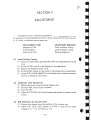
INDEX
SECTION 1.
SECTION 2.
SECTION 3.
•
SECTION 4.
SECTION 5.
SECTION 6.
SECTION 7.
SECTION 8.
GENERAL DESCRIPTION
1.1
INTRODUCT ION
1.2
PHYSICAL DESCRIPT ION
1.3
SPECIFICATION
INSTALLATION
2.1
PLANNING
2.2
INSTALLATION OF SCANNER UNIT
2.3
INSTALLATION OF DISPLAY UNIT
2.4
INITIAL OPERATION AND CHECKOUT
OPERATION
3.1
OPERATING CONTROLS
3.2
USING THE CONTROLS
3.3
NAVIGATION WITH THE RADAR
3.4
DETERMINING YOUR RADAR LINE ·OF· SIGHT RANGE
3.5
FALSE ECHOES
ADJUSTMENT
4.1
LOCAL OSCILLATOR TUNING
4.2
COMPARATOR LEVEL ADJUSTME NT
4.3
AVR ADJUSTMENT
THEORY OF OPERATION
MAINTENANCE
6.1
GENERAL
6.2
SCANNER
6.3
DISPLAY
PARTS LIST
DRAWINGS
- i-
SECTION 1
GENERAL DESCRIPTION
1.1 INTRODUCTION
Congra tulations on selecting the APELCO LDR 9910 Radar for your
radar navigation needs.
Whether you purchased this radar because of its compactness or
power economy, ease of installatio n, or long term reliability, one thing is
certain; the moment you turn on your LDR 9910 you'll know you are
seeing a revolutionary new concept in rad ar technology at work.
Radar signals are "st ored" on an LCD display with chart like clarity
and detail. A single glance at your LDR 9910 display will give you a
complete and accurate 360' radar picture of other vessels, bouys and land
fall surro unding your vessel.
The EBL and VRM allow you to measure target bearin g and range
with high accuracy, and the Seaguard Alarm can alert you of tar gets
entering into your safety zone.
A unique feature even allows you to "freeze" the picture for high
accuracy bearing and range mea surements.
With additi onal functions of "Offset", "T arget Expansion" and
"Interference Rejection" it should become apparent that human engineering and operational simplicity have been considered foremost in the LDR
9910's design.
However, please rememb er tha t the LDR 9910 is an aid to navigation
and will provide you with valuable information concerning objects ar ound
your vessel. The radar does not replace any requirements for maintaining
a concentrated visual observation and look out durin g the piloting of your
vessel.
We trust that you will enjoy man y years of excellent performance ,
reliability, and smooth sailing with your new LDR 9910 Rada r.
-1-
)
1.2
PHYSICAL DESCRIPTION
1.2.1 General
The APELCO LDR 9910 Rader (product code M88344) consists of the
following :
APELCO
ITE M
PRODUCT CODE
Display Unit
M88345
1 ea.
Scanner Unit wl inter unit cable
M88307
1 ea.
Power cab le assembly (2m)
CFQ·2176
1 ea.
Instructi
on
Manu
al
7ZPRD0153
1 ea.
1.2.2 Scanner Unit
The antenna, tra nsceiver, and power supply are combined within an
18 inch radome which is made of AES plastic. A small flexible cable
connects the scanner unit to the display unit. The radome cover is secured
to the scanner base pan by four clamping bolts and provided with a rubber
gas ket to seal the unit fr om the weather and spray.
1.2.3 Display Unit
The Display Unit is enclosed in a drip-proof case and can be easily
mounted on top of a chart table , or installed against a bulkhead . All
controls for operating the LDR 9910 Radar are located on the front panel
and positioned for easy adjustment during day or night use. A bearin g
scale is around the screen and is used to determine the relative bearing to
targets.
1.2.4 LOR 9910 Optional Items
M88322 - Universal Sailboat Mast Mount . attractively styled for
the LDR 9910 - fits all masts from 2" and up.
M8&'l23- 10M Extension Cable· Plugs into existing antenna cable
assembly and allows up to 30 additional feet of separation
between display and antenna unit.
1037339-1- Raw Extension Cable - For installations when 10Mextension cable is not required :
- 2-
1.3
SPECIFICATIONS
1.3.1 General
8 nau tical miles
Better tha n 65 m on 0.25 nm
ra nge
1) Maximum Range
2) Minimum Range
3) Range Scales
Range
Range Ring Interval
No. of Rings
0.25nm
0.5 nm
nm
1
nm
2
nm
4
nm
8
0.125nm
0.25 nm
0.5n m
Inm
2 nm
4nm
2
2
2
2
2
2
4) Range discri minat ion
5) Range ring accuracy
•
6) Bearing accuracy
7) Liquid Crystal Display
8) Environmental conditions
Scanner Unit
Display Unit
9) Input Power Requirement
10) Power Consumption
Better tha n 55 m
Better th an ± 2.5% of maxim um
range of the sca le in use. or 22 m,
whichever is the greate r.
Better than ± 1 degree
Effective area 92 x no mm
Temperature - 15'C to +50'C
Humidity Up to 95% at 35'C
Wind Velocit y Up to 50m/s as
relative
Temperature -15'C to 50'C
Humidity Up to 95% at 35'C
13.6VDC± 15%
35W (approximately)
1.3.2 Scanner Unit
Diameter of radome
.1) Dimensions
18"(450mm)
Height
9.8"(227mm)
Approximately 12.1 lb. (5.5kg)
Hori zont al
Hori zontal
6'
Vertical
25'
Better than -21 dB
2) Weight
3) P olari zation
4) Beam width
5) Sidelobes
-3 -
6)
7)
8)
9)
10)
11)
12)
13)
Rota tion
Drive motor input vo ltage
Transmitter frequen cy
Peak power outp ut
Transmitter tube
Pulse length
Pulse repeti ti on frequency
Modulato r
14) Duplexer
15) MIC fr ontend
16) IF amp lifier
17) Overall noise figur e
- 4-
Approxi mately 27 rpm
12VDC
9445 ± 30 MH z
T yp. lKW
Magnetro n (AMC·l)
0.3us
920Hz
Solidsta te modulator dr iving
magnet ron
Tvjunction with Diode Limiter
Bal anced mixer and FET osc.
Center frequency
60 MH z
Bandwidt h
4 MHz
Better than 10 dB
1.3.3 Display Unit
1) Dimensions
2) Mounting
3)
4)
5)
6)
7)
8)
Weight
Range scales
Range rings
Bearing synchron izing system
T uning
Bea ring sca le
9) Ship's headin g marker
10) Controls
i.
•
Widt h
7.44" (189 mm)
Depth
3.75" (I ll mm)
Height
8.86" (22S mm)
Table, overhead, or bulkhead
moun ting
App ro ximatel y 3.3 lb. (l.Skg)
0.25, 0.5, I , 2, 4, 8 nm
0.125, 0.25, 0.5, 1, 2, 4 nm
Motor encoder
Man ua l
360' sca le graduated at intervals
of IS'
Electrical
POWER (ST -BY/ OFF, X·MIT /
OFF)
RANGE (up/ down)
TUNE (up/down)
GAIN (up/down)
SEA CLUTTER (up/down)
VRM (up/down)
EBL (up/down)
ALARM (up/down)
CONTRAST (up/down)
IR (SW)
EXP (SW)
RAIN CLUTTER (SW)
OFFSET (SW)
SHM (SW)
RINGS (SW)
HOLD (SW)
DIMMER (SW)
L/L (SW)
1.3.4 Inter-Unit Cable
Scanner-Display
Type of Cable
1037339-1
Standard Length Maximum Length
6m
15 m
- 5-
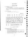
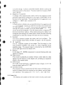
1.3.5 CABLE IN FORMATI ON
Composite ca ble t ype 1037339· 1
T his cable is a v inyl-cove re d, shielded, 11 conducto r ca ble cormect ing the sca nner unit w ith the display unit. T he specifica tion of the cable
is as follows :
VINYL- COV ER
SHIELD
Coductor Cross Section
(No .)
(mm' )
Conductor
Type
Color
Remarks
1
0.5
19/ 0 .18
2
0.3
12/ 0. 18
Black
Shielded
3
0.3
12/0 .18
White
"
4
0.3
12/0.18
Red
"
5
1. 25
50/ 0 .18
Black
250 V
6
1.25
50/0.18
White
250V
7
1.2 5
50/ 0.18
Red
250 V
8
0.3
1210.18
Green ·
600 V
9
0 .3
12/ 0 . 18
Yellow
250 V
10
0.3
12/ 0.18
Brown
250 V
11
0.3
12/0.18
Blue
250 V
FIG. 1·1
Coaxia l
SPECIFICATION OF COMPOSITE CABLE
- 6-
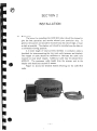
SECTION 2
INSTALLATION
2.1
PLANNING
T he layout for insta lling the LOR 9910 radar should be planned to
give the best opera tion and serv ice aboa rd your part icular ship. In
general, the scanner unit should be mounted atop the cabin bridge, or mast
as high as possible. The display unit should be installed near the helm at
a convenient viewing position .
A 6 meter length of viny l-covered, shielded, 11 conductor cable is
furnished for interconnecting the two main units (scanner and display).
T his length of cable should be sufficient to fabricate the cable runs
required on most small vesse ls. Addit ional cable may be orde red from
APELCO. The maximum cable length from the scanner unit to the
display unit should not exceed 15 meters.
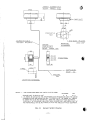
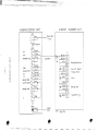
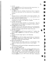
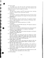
Figure 2·1 shows the General System Drawing for the LOR 9910
radar .
- 7-
~4S0
MB B 3 0 7
S CANNER U N I T
WEI GHT
APPR OX . 5 .5k q
I
I
!
-,
\
f
I
!
'~ ~
\\
II
¢:::l CABL E I NLET
blmJ
20 0
~
(5'1Ir:
FO R ECAS TL E
¢:::J
S/16-IB U NC
COMPO S I T E CAB L E
1037 33 9-1 ( ~ 12 . SMAX I
MOUN TING
MBB 3 4 S
4P L A CES
2 0mm D E EP
DIMENS IO NS
D I SPLAY UNIT
WEIGHT
APPRQX. 1.5 kg
~
~
f-fl
t)1
¢:::lJ 4 0 I
¢:::l J40 2
CONN EC T ORS
¢:::lJ404
6J.k
12014 ,7 °'
SHIP'S MAINS
DCI2V
2A
CFQ-2 176
N
o
1
I
(2m)
in
MOUNTI NG DIM E NSIO NS
NOTES:
I.
THE DIST ANCE BETWEEN THE UNITS I S AS FOLL OWS:
STANDARD
MAX
6 m
IS m
SCANNER UNI T TO DI SPL AY UNI T
2. TO ASSIST IN MINIMIZI NG THE INTER FERENCE ON FREQUENCI ES USED FOR MARINE
CO MMUNI CATI ONS AND NAVIGATION DUE TO OPERATIO N OF THE RADAR. ALL CABLE S
OF RADAR ARE TO BE RUN SEPARATE L Y FROM THE CABLES OF RADIO EQUIPMENT.
ESPECIAL LY I NT ER- WIRI NG CABLES BETWEEN SCANNER UNIT AND DISPLAY UNIT OF
THE RADAR SHO UL D NOT BE RUN PARALLE L WITH THE CABLES OF RADiO EQUIPMENT.
FIG. 2-1
I
i
I
General System Drawing
- 8-
2.2
INSTALLATION OF SCANNER UNIT
2.2.1 Selecting the location
Selecting an adequate location for the scanner unit requires careful
consideration. On many small ships, the unit can be installed directly on
the top deck of the wheelhouse near the ship's centerline. Th e unit should
be mounted as high as possible on the ship to ensure best performance at
the maximum range.
Th e radiator beam should not be obstru cted by nearby large objects.
Locat e the unit where lar ge structures such as superstructures , searchlights, horns, or masts are not in the same horizo nta l plane, otherwise,
blind areas and false tar gets can appe ar on the rada r screen.
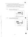
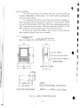
2.2.2 Mounting the Scanner Unit
'.
Using the outline drawing of figure 2-2 as a guide, install the scanner
unit and secure to the mount ing surface. The correct mounting hard war e
is stainless steel hexhead bolts 5/16", 1 W' long with 18 UNC thread. A
flat and locking washer should be used. The mounting surface for the
scanner unit should be parallel with the ship's waterline. If mounting
directly to a top deck does not give sufficient height or clearance. a radar
mast or pedestal may be used to raise the unit.
¢::::J
FOREC~STLE
~
I
200
I
j
'"0
·1
i
S / 16- 18 U HC
CO LOR
WH ITE
WEIGHT
....PPRQX. 5 .510.9 11 2.1 lb1 1
FIG. 2·2
Moun ting Dimensions
-9-
" PLA CES
ZOmm DE EP
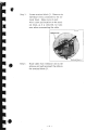
2.2. 3 Disc onnecting and Reco nnect ing the Sc anner Unit Cable
T he scanner unit will be supplied with the interconnect cable hard
wired at the antenna and a plug for connec tion to the indicato r. If your
install ati on does not allow you to run the cable with the plug attached, the
ha rd wired cable can be disconnected from the scanner.
Refer to the following ste ps to disconnect the cable from the scanner
unit.
Step 1 :
Remove the 4 clamping bolts securing
the radome and remove radome.
~
... - ".
Clamping bolts located undernearth radome
Step 2 :
Loosen watertight gland where the
interco nnect cable enters the antenna.
i
"
,Apelco
._---
' --.
_, 0/J
. --....~.
~~.
~
_._~ ~-
W ater tight gland
- 10-
'1
I
I
I
,
Step 3:
Locate terminal block J1. Remove the
individual wires connected to the terminal block. Mak e note of each
wire's color and loca tion on the terrninal block, as it is removed, for reference when reconnect ing the cable
Terminal Block J 1
Step 4 :
Route cable from indic ator unit to the
antenna unit and reconnect the cable to
the terminal block J1.
- 11 -
•
2.3 INSTALLATION OF DISPLAY UNIT
2.3.1 Selecting the Location
Ideally. the display unit shou ld be located at the helm so the radar
screen can be viewed while look ing foward from the wheel. T he display
unit ca n be mounted on top of the chart ta ble or insta lled aga inst the
bulkhead.
2.3.2 Mounting the Display Unit
Using the outl ine of figu re 2·3 as a guide. inst all the display unit and
secure to the mounting surface.
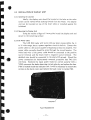
2.3.3 DC Power Cable
The LDR 9910 radar will work with any ship's mains within the 11
to 16 volts range, since a powe r regulator circuit is built- in. Connect the
power cab le to a DC source ca pable of supplying at lea st 2.5 amperes. The
power cable normall y should be wired through the circ uit breaker . Th e
white lead wire of the power cab le should be connected to the positive
source terminal and the black lead to negative source terminal. T he
shielded wire should be connec ted to the ship's RF grou nd. Should the
power connectio ns be inadvertentl y reversed, protective fuse F401 (3A)
will blow. Recheck the input power leads for correc t polarity with a
YOM, reconnect the leads observing correc t polarity and replace the fuse.
F401 is located inside the indicator unit. It will be necess ary to remove the
screws on the bac k cover and remove the back cover to locate F401.
FUSE(F4011
Fuse Replaeement
- 1 3~
~f.·
.
iL--
.
'~~~~~~
~:"~~-~~,?;Y;'i~1~"'it~~~,;"1: }; ';. "' ' ,_.
M 8830 7
M 88345 DISPLAY UNIT
J4 0'
,..---,
.WHT
I
2: ~ , J
L_;trJ
J8 L K
f I
I
SCA NNER UN IT
Ship's Mains
12Vdc
I
I
o RF Ground
J4 0 2
r~--; 50 BLK
t- 7 V
-m
::>
+ 12 V
Thlnsmitte\" Trig.
~
c:
~
~
Vi deo
0
0
Tu n i n ~
::>
::>
'"g
0
::>
'"
Con h OI
:
: BLK_
4
I
I
I
o
' A
Bea.ri nj Reset
Ga.in- STC Ca nhal j
,
6_
:COAJ.--
7
: VEL v-
9
~ 50 WHT
~ 50 RED
'0
I
,
n,
112.
0
B e a.r j n~ Pulse
T
~-
B
2 A
GRN
2_
3 .....
1
,3....
I
114
: 15
0
I
:
I
--;1
.
BLU
f--'-'-'-
WHT I GS
YEL ~
50 BLK I 3~
COAX ~
~
-¥
BRN
.L
T
I
1
RED
GRN
I
@
COAX fjE
Bea.Hn~ Reset Pulse
Ga. in- STC Control
Tunin3 Cont rol
Video
V DR
I
~
6P
:!fu:
BeaH o3 Pulse
TlR
BLK
L_rJ
I
~
G SR
t7
T
J4 04
~.
~
•A
-rv
lt6o :' BR N
E
50 REV
1
WHT
l RED
I
10 3 73 3 9 - 1
B LU
I
J '
50 WHT , - - -
- _':. _ -
~
--.:..=...
Tta.nsmitter TriS'
LORAN
DATA
~.
.1(.
50
La. r3e Wit-a.
.
I
.,
t,
t
..I
!
.,j
.-.,i
.':1
2.3.4 Loran Interface
T he LDR 9910 radar will interf ace with any Loran that has the
standard NMEA0182 or 0183 output. All curren t Apelco and Raytheon
loran s have this output. .
T o connect the LDR 9910 to your lora n unit, all that is needed is a
500 coax cable with the a ppr opri at e connectors. The connector needed
for the LDR 9910 (J404) is a BNC type. Most lor an manufacturers also use
BNC connecto rs for their output. 500 coax cable such as RG58 A/ U with
BNC connectors can be obtained from many electronic stores.
If you do not connect the radar to your Loran C. be sure that the
BNC connector plast ic cover is not removed.
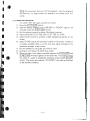
2.3.5 Connecting the cables
Connecting the cables to J401, ]402 and ]404.
Figure 2·3 deta ils the connecting of the display unit.
10 0
150
I
B
0
m€m!
~
¢::JH
~
<fJ
N
N
OI IPOWER)
J¢::J J 4 021 ANT ENNA SIGNALI
:J¢::JJ4041LORAN
I-
161
15
189
70
I
I NTERFAC E!
CONNE CTORS
26
II I
4 -«; 5
0
-
"r- 0
N
or-
0
II
m
120 14 .7 ' )
161 16 .3 ' )
I
r-,
~
COL OR
0
tn
MOU N TIN G D I ME NS IO NS
FIG. 2·3
BEZ EL,CASE ANO BASE
WEIG HT
APPROX. 1.5 kg 13 .3 1bsJ
DISPLA Y MOUNTING GUIDE
- 14 -
WINTER WHITE
I
I
I
I
I
I
I
fJl
I
Ii
I
•
•d
2.4
INITIAL OPERATION AND CHECKOUT
2.4.1 Inspectio n after Installation
After completing the installati on, it is necessary to assure that all
the ste ps of the installation were accomplished in accordance with the
instruction s.
In parti cular. inspect to insure that the cables are not crimped or
damaged and the input volta ge connected accurat ely ; the securing bolts
of all equipment is tightened ; and that the connect ion of the power cable
shield is made properly to RF ground.
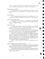
2.4.2 Operational Check
Apply power t o radar and swit ch to st a ndby by pressing
ST·BY/ OFF I switch. In approximatery 90 seconds the sign on the
screen should change from "LDR 9910" to "READY".
Pr ess the IX·MIT/ o FF I switch and observe presence of a sweep.
range rings , and heading line. While selecting different ranges, observe
that the sweep is the correct length and has two range rings on each scale.
Set the GAIN control and observe the presence of targets and noise.
Set SEA CLUTTER control on 1/2nm scale and note the reduction of
close in ta rgets.
After approximately 10 minutes of operation, set the TUNE control
and check that maximum target returns occur at the center of the control
range. If tuning control is off center, refer to section 4.1.
I
2.4.3 Relative Bearing Alinment
Th is alinment must be made when the radar unit is installed . Failure
to perform this procedure can result in incorrect target bearing readings.
Proceed as follows :
1) Locate and remove the soft plastic cover located on the bottom of the
display unit. Refer to figure 2-4.
2) Identify a suitable target (e.g., buoy, etc.) preferably between 1 and 2
nm in range on the screen.
3) Visually locate the target and line the bow of the vessel up with the
target.
4) Locate the bearing of the target on the display.
5) Put the EBL marker on the target.
6) · Set BRF (Bearing Adjust Fine) at its mid position .
7) Pr ess the RINGS key until th e buzz er sounds and the display indicates
"BEARING ADJUST".
8) Adjust BRC (Bearing Adjust Cours e) so that the target will be
within ± 10 degree of the heading line on the display and simulta-
- 15-
I
;:,.:
: ~l
::;{
·s:I
{J
)~
·1
' -~
;~
,"
;~
:;1
,
:!
neously the beeper should sound continuously. Th en ad just BRF until
the tar get is loca ted und ern ea th the heading line on the displa y.
9) Press the RINGS key un til the "BEARING ADJUST" read out extinguishes, this will resto re normal operation.
10) Proceed to the next ad justment (2.4.4) before reinstall ing the soft
plasti c cover.
" ~
:"~
· . i~
"I
' i'
·;1
;:;
.~
.';j
DISPLAY OF
-.~:~
'~
1 I
I
I
I
I
BEARING ADJUST MODE
•
D
. ~l,1
)
•
.-',.,
~~
ADJUS T
.'
~,~
,-,
.-. ..
,
I
1
.5
y
I
\
,
EBL 285 ' I R E X RC
VRM
N 4 2 °20 .00
ALM
W7 1°0 5.00
t)
.~
BEARING ADJUST
·,1
".
;r.
., ,
"
COARSE
FINE
I BAC I
[ill]
i
i'
"
f l;
.,""
: J.
, 1~1
)f.
~=b:!.,h=+1,-
PC -401
1
I
PC 40 Z
.~
I
I
I
I,
I
I
I!
(,
!'
I
1
o non ADJUS T
,
f
,
."j .
'I, . .
CO M PAAATOR
ADJUST
TUNE PR ESET
FIG. 2·4 BEARING AND 0 NM ALIGNMENT
- 16 -
I
I
I
I
I
I'i
\
2.4.4 0 NM (ZERO NM) ADJUSTMENT
Set the ra nge at O.25nm and observe a target at a known (nearest)
dista nce.
(l) Locate a straight dock , seawall or brid ge.
(2) Position the vessel parallel to the straight target.
(3) Adjust ZERO so that the object app ears to be strai ght on the display.
(4) T he init ial alignments are complete, reinstall the soft plastic cover.
~
I
I
I t
I
Pushing-D isplay timing early
Pulling-Display tim ing tate
Normal
NOTE : T he tune preset and the compa rator controls are pre adjusted at the
factory for proper opera tion. Normally furt her adjustment is not required and
should not be attempted by persons othe r than service technicians.
r
I
r-
I,..
I•
I
r
,
- 17-
SECTION 3
OPERATION
3.1
OPERATING CONTROLS
Genera lly the operation of the LDR 991 0 is easy straig ht foward .
However . the navigat or who knows the layout and understands the tunctions of the various controls will obtain the best performance from his
equipment.
3.1.1 Layout of the controls
Layout of the contro ls is shown in figure 3·1
DOWN KEY
UP KEY
DIM
ST-BY
---oFF
L/L
SHI.4
EXP
IR
CaNT
X-I.t IT
OFF
RIGS
OF SET
H LD
'--+-~I'--+-~I'--+--'
LM
18
8
FIG. 3·1 OPERA riNG CONTROLS
3.1.2 Function of the controls
1) POWER (IST.BY/ OFF l. lx .MIT / OFF!)
In the "OFF" state there is no power applied to the radar system
(without power supply control circuit).
Upon pressing the IST. BY/ OFFI switch. power is supplied to the
scanner and display un it, and "LDR 9910" is displayed on the screen
indicating the warming up condition.
- 18 -
•
•
•
•iii
•
t) •
•
•j
i
I
i
"!.
""
~ .
I
t> j
~
'r~
I
.~
I
I
1
I
I
,•
••
•I
>
2)
3)
4)
}
,.
i1
5)
.,N
III
II
6)
Approx imately 90 seconds after initial switching to "ST ·BY". the sign
will disappear from the screen and the sign "READY" will be displayed on the screen. T he radar is now in ready and available for
operation.
Press ing the Ix.MIT / OFFIswitch enab les the radar to transmit and
targets will be displayed on the screen.
By pressing the IST.BY/OFFI switch the radar will return to the
standby condition with the transmitte r "OFF" and "ST·BY" appears
on the screen.
By pressing the IST .BY/ OFF Iand Ix.MIT / OFF! switches simultaneously, the radar will turn off and all alpha -numeric informa tions will
extinguish.
T UNE
Press the IT UNEIkey until th e area aro und the "T " on the bar graph
located on the lower righthand corner of the display dark ens. Now
press the blue Iu pi or IDOWNI key to adjust the tuning of radar.
Observe the display while adjusting the tune control and adjust for the
most targets. The bar gr aph gives an indicati on of the tune setting.
GAIN
Press the IGAINI key ustil the area around the "G" on the bar graph
darkens. Now press the Iupi or IDOWNI keys to adjust the gain. The
gain control varies the sensitivity of the receiver.
SEA CLUTTER (S.CL)
Press the Is.cLI key until the area ar ound the "S" on the bar graph
darkens. Now the sea-clutter adjustment can be controlled by (less
than 3 miles) clutter from waves .
ELECTRONIC BEARING LINE (EBL)
Press the IEBLI key until the area around EBL darkens. A digital
bearing readout will appear and a dotted bearing line will appear on
the screen. By pressing the Iupi or lOOWNIkeys to EBL line can be
moved to any location on the screen to take a relative bearing
reading. When the Iu p iorloowNI keys are first pressed, the EBL line
moves in l' increments. If you hold the key in, the EBL will move in
large increments. To tum off the EBL, press the IEBLlkey.
VARIABLE RANGE MARKER (VRM)
Press the IVRMI key until the area around VRM darkens. A digital
range read ing will appear and a dotted range ring will appear if the
ran ge of the radar is more than the digital VRM readout. Th e Ju p ior
IDOWN I key will vary the VRM to enable you to tak e a range reading
of a target. To turn off the VRM, press the VRM key.
- 19-
£41,;;:;4
•
7) RANGE
Press the RANGE key until the area around the ran ge darkens. The
Iupi or DOWN key will select the desired range.
8) DIMMER (DIM)
The IDIMI key has four sett ings, off and three levels of brightness.
Press the key alterna tely until the desired level of back- lighting is
obtained.
9) LlL
This key turns on or off the display of Lat/Long coordinates. The
LDR 9910 must be interfac ed with a loran C for the function to work .
10) SHIPS HEADING MARKER (SHM)
This key turns the ships heading marker on or off. Th e mar ker will
extinguish only as long as the SHM key is pressed.
11) TARGET EXPANDER
Th is key turns the tar get expander on or off alternately. When the
targ et expander is on, a ll targets are enlarged for better visibility.
12) INTERFERENCE REJECT (IR)
The [!ffi key will turn the inter fer ence rejection on or off alt erna tely.
When on, an IR charactor will appear on the screen, T his feature will
eliminate interference ca used by other radars in the area.
13) CONTRAST (Ca NT )
Press the ~CIN T I key until the area around the "C" darkens, then
press the UP or IDOWN I key to adjust the contrast of the display.
14) RINGS
Th is key turns the ra nge rings on or off alternately.
15) OFFSET
7
Th e 10-=
F=
FS
="'E="'T=o11key shift s the display approximately 114 radius down
expanding the display area in front of the vessel. Press the key a
second time to rest ore the normal display.
16) RAIN CLUTTER (RCL)
T his key turns the rain clutter contr ol on or off alt ernately. Rain
clutter is to break up the returns from rain or snow ta rgets.
17) HOLD
Pressing this key will fr eeze the display, releasing the key returns the
unit to its normal displ ay .
18) SEA GUARD ALARM (ALM)
Press the IALMI key un til the ar ea aro und the ALM darkens and a
range read ing appears. Press the Iupi or jDOWNI key to adjust the
range of the seaguard. A bro ken double ring will appear on the screen
at the set range. When first turn ed on, the seaguard will cover 360' .
Press the IALMI key once for 180' in front of the vessel. Pressing the
- 20-
•
•I
•
•
•
•
•
•,
f) •
.'
,j~
I
i
-.~
·f.
I,
()I
I
J
I
•o
I
•
IALMI key once more will turn off the seaguard. Once the seaguard
has been set, if a target enters the seaguard, an audible alarm will
sound.
3.1.3 OPERATING PROCEDURE
l}
2)
3)
4)
5)
6)
7)
8)
9)
T o switch "ON" the radar , pr oceed as follows:
Press the 1ST- BY/OFF! switch.
After the display changes from "LDR 9910" to "READY" (approx . 90
seconds), press the IX-MIT/ OFF Iswitch.
Set the contrast contro l to obtain the desired contra st.
Assure the RAIN CLUT T ER. SEA CLUTTER are "OFF".
Adjust GAIN contro l to prod uce a light backgr ound speckle on the
screen.
Adjust T UNE contr ol for maximum echoes on the screen. If there is
no ta rget available (that is, in the open sea) adjust tunning for the
maximum strength of sea clutter.
Set the RANGE for the scale you wish to cover.
As desire. rain clutte r, IR, EXP, Sea clutt er.
When the radar is no longer required. depress the 1ST -BY/ OFFI and
IX-MIT/ o FFIswitches together at the same time. If you wish to keep
the rad ar in a state of immediate readiness, press the 1ST.BY/ OFFI
switch. The screen will indicate "ST ANDBY", the radar will be kept
in the standby conditio n.
-21-
3.2 USING THE CONTROLS
3.2.1 TUNE Control
The magnetron and the local oscillator may ta ke about 10 minutes
to completely stabilize on frequency. So after switching "ON" and tuning
initially, the tuning should be rechecked after the first 10 minutes.
Symptoms that the equipment may be out of tune are a lack of
distant echoes or the appearance of double echoes (one echo behind
another) . Th e coarse method of tun ing is described in Section 4. Normal Iy it is possible to fine tune th e radar by selecting a comparatively weak
echo and then press the TUN E key and the UP or DOW N key until the
strongest echos and best definitio n are observed.
3.2.2 GAIN Control
The correct sett ing of the GAIN is for light background speckle to be
just visible on the screen. T he equipment is then in its most sensitive
condition. Objects will be detected at the greatest possible ra nge. With
too little gain, wea k ta rgets may be missed and there can be a decrease in
detection range. With excessive gain (a few) extra targets may be brought
in, but the contrast betwee n echoes and back ground noise will be
substantially reduced, maki ng target observation more difficult.
In crowde d regions gain might be temporaril y reduced to clarify the
picture. T his must be done wit h ca re since important marks may be
missed. With gai n at its norma l setti ng, clutter from rain or snow may
obscure the echo from a ship inside a squall or storm. A temporary
reducti on in gain will usually permit the stronger and more distinct ship's
echo to be distinguished.
Detection of ta rgets beyo nd th e storm may, however , require slightly
higher ga in than norm al, since the clutte r may have attenuat ed, but not
completely.obscured, echoes from the targets. Th e GAIN should be alwa ys
reset to its normal level as soon as any temporary alterat ion is no longer
required.
3.2.3 SEA CLUTIER Control
Whereas the GAIN contr ol affects the strength of echoes at all
ranges, the effect of the SEA CLUTTER contro l is grea test on short -range
echoes, becoming progressively less as range increases. Th e SEA CLUT·
TER control is only effective up to a maximum of ab out three miles.
The SEA CLUTTER keys reduce the strength of false echoes received
from wav es at short range. The setting used should be sufficient to reduce
the strength of signals until clutter appea rs only as sma ll dots , or until
small ta rgets can be distingui shed, the setting should never be advanced so
- 22 -
- c:
far as to blan k out all clutt er ent ire ly.
The sensitivity level of the SEA CLUTT ER can be set in 32 steps , thus
ena bling an optimum picture to be obt ained under adve rse weather
conditi ons.
The SEA CLUTT ER keys may be used to reduce some rai n or snow
clutte r, as well as stro ng sea clutter, in the immediate vicinity of the
vessel. A temporary incr ease in the setti ng will usuall y permit stro ng
echoes from ships, and most navigational marks inside sto rms or squalls,
to be distinguished.
At close range, in crowded regions, the STC level may be temporarily increased to clear the pictur e. T his should be done with care, so as
to avo id missing importa nt echoes. The SEA CLUTTER level should be
always reset to the minimum req uired amount for a normal presenta tion
after any temporary alteration.
I
I
I
3.2.4 RAIN CLUTIER Switch
I
I.
I
,
During heavy rain or snow which ma y clutter the picture. use RAIN
CLUTTER to give better detection between echoes and the clutter. Under
some conditions of sea return. both RAIN CLUTTER and SEA CLUTTER
will help to clarify the pictu re . When viewing large masses of land,
coa stli nes, etc. RAIN CLUTTER red uces the backgr ound and will cause
pro minents shoreline to stand out mor e clearly.
3.2.5 IR Switch
~f
-~,
:t
~,
-
/
\
/
\
\
I
I
\
\
, -,
/
I /
/
I
/'
/
~
/
-----
":::;---- ....
.... -,
-,
'''', x.... >..... -, -,
\
\
/ /
,/
,
-,
--.
...
•.
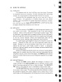
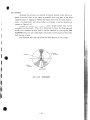
When another ship is using the same frequ ency radar as that of your
own rad ar, interference typically ap pears arranged in curved spokes as
shown in Figur e 3-2. T he radar interference is mai nly noticeable on
longer range scales.
Using the IR switch will eliminate this form of interference as well
as any other form of synchro no us noise.
,-
!:
/
,
\
1
\
I
I
I
\
•
I
FIG. 3·2
\.
RADAR INTERFERENCE
: .i
-23 -
,
I'"
! I
3.3
NAVIGATION WITH THE RADAR
3.3.1 Obtaining a Position Fix
T he LDR 9910 Radar is a n accurate and reliabl e navigat ional aid for
determining your ship's posit ion. Figure 3·3 shows exa mples of alterna'tive methods of using radar sight ings from prominent navigational points
which can be identified on a chart. A position fix based on two or more
navigati onal points will furni sh a more accurate fix. especially when the
points appr oach 90 degrees ap art from your ship's position.
3.3.2 Avoiding Collisio n
T he moment a ta rge t appears on the screen. its range and relative
bear ing should be noted. This is best done on a plott ing sheet or chart.
As in visual observation. "a constant bearing indicat es a collision
cour se".
As soon as a series of plots indica tes a closing ra nge and no significant change in successive bearings. positive action should be considered
mandat ory and "The Regulations for Pr eventing Collisions at Sea" should
be observed.
o•
A..
c
THREE R...NG E " Re s
PLOTT ED D ill CM4 RT
8.
ON E RAN GE A RC AN D ONE
BEARING PLOTTED ON CHA.RT
•
..
[I
!;~
II
. ~~::
.,
II
~, :
C.
TW O 8EA RIN OS PlOTT ED
ON CHAR T
FIG. 3·3
D.
RADA R SCR EEN POSlnON
POSITION FIX METHODS
- 24 -
..
I
I
I
n
I
I,
,
;
3.3.3 Range measurements using the VRM
1) Press the VRM key to display the variable range mark er,
2) Press UP or DOWN key to move the variable range mark er to the
closest edge to the tar get. Target distance will be displayed in lower
character area ,
3.3A Bearing measurements using the EBl
1) Press the EBL key to display the electronic bea ring line,
2) Press UP or DOWN key to move to electronic bearing line to the
center of the target. T he target relative bearing is displayed on the
lower charact er area .
U
r
,
V RM
....
////~
~(t
---..
I
- ... ---
-----.......
"" '"
\\
/
I
\
,I
\\
I --
I
I
\
EBl
I
I
\
\
/
\
/
\ "" " .
--...---------....... '
,.
2
I
8
FIG. 3·4
"
\
~///
\
EBL 2 8 5 " I R E X RC
VRM 6 .GO N 42"20.00
RLM 0 .G4 W 71"05.00~~
RANGE AND BEARING MEASUREMENT
3.3.5 Displaying your position on the rada r display
Press th e L/L key to displa y your present Lat / Long on the LCD of
the radar.
- 25 -
,;
~.
!
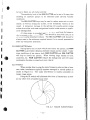
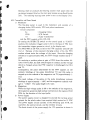
3.4
I,
DETERMINING YOUR RADAR L1NE·OF·SIGHT RANGE
When sea rching for distant targets. your radar line-of-sight ra nge to
the target ca n be a limiting fact or. Radar waves behave like light waves
but they are refracted slightly mo re. increasing the distance to the radar
horizon slightly more than tha t to the optical horizon (however. displayed
range is correct). As Figur e 3·5 shows. the rada r line-of-sight range is a
combinati on of the radar hori zon of your ship's rada r scanner and the
radar horizon of the target.
T he dista nce to the radar hori zon under conditions. may be calculat ed from the formula.
Dista nce (nm) = 2.23 {h
h = Height of the radar scanner off the wat er line (in meters)
For example, a sca nner at a height of 2 met ers has a radar horizon
of 3.2 nm.
A 3 meters cliff has a radar horizon of 3.9 nm. Ther efore. under
standa rd conditions. the cliff should begin to appear on the screen when
the ship closes near er than 3.2 + 3.9 = 7.1 nm.
f - -- -..-
-
• . - 2 .2 3
., .. 2 .23
lJ,
+
at ... 2 . 23 1
-
-
- --
Ih.
#1,
•. .,. , :
-
---I
\r
"
itt na.. tie.l ..... es
h, . h. : in
Ih, • Jh.
..-
m.1~
J
20
15
'0
5
'0
5
8 .
J
- - -- - - - - - - - - - - - 5
J
°
h. \m ,
lJ, +.,ln .m .1
FIG. 3·5
RADAR HORIZON
-26 -
h, Iml
•
•..
•
,
f)1
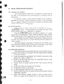
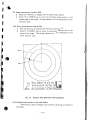
3.5 FALSE ECHOES
Occasionally, signals appear on the screen at positions where ther e
is no target. They are false echoes .
The following are known as the most common false echoes.
3.5.1 Side Echoes
I
I
With every rada r ante nna some radiat ion escapes on each side of the
main beam as side lobes. If they are stro ng reflected by a target, and be
displayed on the screen as an echo. (See Figured-fi)
These echoes often appea r as arcs echoes at each side of the true echo.
~
SID E ECHOE S
I
TRU E ECHO
~.
FIG. 3·6 SIDE ECHOES
f
I
,
f
I
II,
I
I
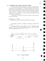
3.5.2 Indirect Echoes
As shown in Figure 3·7, indirect echoes may appear if there is a large
target, such as a passing ship at a short range or a reflecting surface, such
as a funnel on your own ship. The signal, on first striking the smooth side
of the large target, will be deflected. Then it encounters a second target,
the echo will return along the same paths to the scanner. Thus, the echo
from the second target will appear beyond that of the large target but on
the same bearing. The indirect echoes will also appear when the signal is
deflected by the reflecting surface.
TAUE ECHO
SCANNER
,
FUNNel
,,,
r
I
FIG. 3·7
INDIRECT ECHOES
-27-
IN DIRECT ECHO
~
r
I
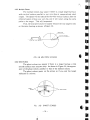
3.5.3 Multiple Echoes
T he multiple echoes may appear if there is a large target having a
wide vertic al surface parallel to your own ship at comparatively short
ra nges. Th e signal will be reflected by the wide vertical surface, then the
reflected signal strikes your own ship, and it will return along the same
pat hs to the ta rge t. T his will be repeated.
Thus, the multi ple echoes will appear beyond the true ta rget's echo
on the same bearing as shown in Figure 3·8.
TRUE ECHO
MU l TlPU ECHOES
FIG. 3-8
MULTlPLE ECHOES
3.5.4 Ghost Echoes
Th e ghost echoes may appear if there is a target having a wide
smooth surface near your own ship. As shown in Figure 3-9, the appearance of the ghost echoes is s imilar to that of the indirect echoes.
T he ghost echoes appear on the screen as if you saw the target
reflected in a mirror.
•I
..
II
•
fl.
•
.. ; '
GHOST
ECHOES
TRu e ECHOES
FIG.
3-9
GHOST ECHOES
-28 -
3.5.5 Shadows
Although the scanner unit should be ideally placed where there is a
good all-around view, as far away as possible from any par t of the ship's
superstruct ure or rigging to reflect the beam. there may be some obstructions. An obstruction will thro w eit her a complete or partial shadow as
shown in Figure 3-10.
If there are tar gets in a shadow sector. ta rget echoes may not be
displayed on the screen. Th us. it is important to know the bearings and
width of all shadow sectors, and it can be checke d by turning the SEA
CLUTTER contr ol to zero when light rain clutte r covers much of the screen
and the sea is calm.
Any Shadow will then be shown as dark secto rs in the clutter.
i
I
I.
1
j
,-
o
PAfl TI" L
SHADOW
SC,,"N NE R _____
". f--- - f'"
PARTIAL
SHA OOW
~
f
FIG. 3·10
SHADOWS
- 29 -
I.""'-.,
SECTION 4
ADJUSTMENT
Although the radar is delivered adjusted for optimum performance, it may
be necessary to make adjustments after a major component has been replaced
or if a fault is suspected during ope ra t ion.
ADJUSTMENT REQUIRED
Local oscillator tuning
Local oscillator tuning
Bearing alignment
REPLACEMENT ITEM
Magnetron V201
Front end E301
Reed switch S101
4.1
Loca l Oscillater Tuning
(l) About 10 minutes after operating the radar, set range between 0.5 and
2 nm.
(2) Set the TUNE control of the display to its midposition.
(3) Remove the display's lower cover
(4) Set the GAIN control so that noise on the sweep trace is discernible.
(5) Adjust T NP (T UNE PRESET) in the display unit to obtain max imum
amount of echoes on the screen.
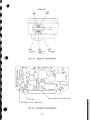
4,2
Comparator Level Adjustment
(I) Remove the lower cover from the display unit.
(2) Set the GAIN contro l fully clockwise.
(3) Turn IR "ON"
(4) Adjust CPL (PC401) unt il some background speckle is present on the
scree n.
4.3
AVR Adjustment (In Scanner Unit)
Remove the radome from the pedestal of the scanner unit.
(2) Adjust RVI (AVR AD]) located on PC201 so that the dc output
voltage at j l +7V on PC201 is +7V .
(l)
r-
- 30 -
•
i·
tit
BEARING AOJUST
FINE
COARSE
[ill]
I BAC I
l==ddd==l;I---
PC ~O I
\="=Fi=r=lr--Pc ~OZ
•
I ZERO I
I CPl
o nm ADJUS T
CO MP A RATOR
ADJUS T
FIG. 4·1
t
I TNP I
TUNE P RESET
I'
DISPLA Y ADJUSTMENT
,g
0
I
ra
r
(
,t,
(
=0
--'
r
?' ,16
Output voltage + 7V DC check point
AVR voltage + 16V DC check point
FIG. 4-2 SCANNER ADJUSTMENT
- 31-
",
SECT ION 5
TECHNICAL DESCRIPTION
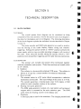
5.1 BLOCK DIAGRAM
5.1.1 Gener al
T he overall system block dia gram can be considered as being
comprised of two ma in sections. One for the scanner unit circuit diagr am ;
the other for the display unit circui t diagram . The following description
of the block diagram expla ins the individual circuits describ ed in Chapte r
5.2 and 5.3.
T he motor -encoder and SHM pulse generator are used to synchronize the bearing of the radar display, display timing and tr ansmittri ggering . Sett ing the operate switch to "STBY" position activates the
power supply which in turn pr ovides opera ting voltages to all circuits of
the radar. After about 90 secon ds, setting the operate switch to "ON"
position allows transmitt er triggering and the rad ar becomes oper ational.
5.1.2 Scanner Unit
T he scanner unit includes the scanner dri ve mechanism together
with the tr ansmitter and receiver. These three sections ar e housed within
an 18" rad ome.
1) Radiator
T he r adiator is a hori zontally polari zed, PCB array. Th e radia tor is
driven at 27 rpm by a motor-encoder via reducti on mechanism.
2) Motor-encoder
The scanner motor is a DC motor which incorporates a reduct ion
mechan ism and encode r. The input voltage of the motor is 12 V DC.
The encoder genera tes a bearing pulse every 0.176 degree of 2048
pulses for each compl ete rotation of the radiator.
3) Bearing reset pulse ge nerator
The SHM pulse gener ator consists of a reed switch and permanent
magnet which is mounted on the main reduction gear. T he SHM
pulse resets the bearing counter in the display unit.
4) Modulator
A line-type pulse is used in the modulator. The charging method used
- 32 -
•
•
•
•b
•
• ••
•..
•
•b
•
t.
II
I
I
I
B
I
I
I!
~
!
I -
,
i
;
f
ce
is via DC charge. A silicon co ntro lled rect ifier (SCR) is used as the
high power switch of the pulser. T he pulse repet ition frequency (PRF)
rate is 920 Hz.
5) Magnetron Transmitter
A voltage of the required pulse widt h is fed to the magnetron which
generates high energy oscillations in the region of 9445 MHz for the
dur ation of the input pulse. The opera ting point of magnetro n is at a
voltage of - l.85KV and a curre nt of 2A.
6) Duplexer
A Diode Limiter is fitted in the wavequ ide between the magnetro n and
the micro frontend. It serves a s a barrier to protect the frontend from
the high amplitude r.f. energy genera ted by the magnetr on. While
this high RF power is present , the diode limiter behaves like a short
circuit across the wavegu ide. T hus the output power of magnetron is
directed toward s the radiat or. Echo pulses entering the radi at or and
waveguide pass through the d iode limiter which deionizes following
tr ansmission so that echo ene rgy will reach the micro front end.
7) Frontend
Th e micr o frontend contains th e mixer and local oscillator. Th e
micro frontend output feeds a 60 MH z IF signal to the IF amplifier.
8) I.F. Amplifier
The I.F. amplifier consists of two stages. The first stage is a low
noise tr ansistor amplifier ; the second is a linear integrated circuit
amplifier stage. The second stage is controlled by the GAIN·SEA
CLUTTER signal from the display unit.
9) Detector
In this stage, I.F. (60MHz) component is removed leaving video rate
signals for display .
10) Video Circuit
This circuit is primarily an em itter follower which feeds the video
signal from the detector to th e display unit providing an impedance
match to the coaxial cable .
11) AVR Circuit
T he AVR circuit genera tes a regulated output voltage of 16 V DC
from the ship's mains of 12 V DC.
12) Converte r Circuit
The convert er circuit converts the 16 V DC output of AVR into three
levels of voltage which are required for the scanner and the display
unit operat ion. The outputs a re + 7 V, + 12 V, and + 220 V DC.
5.1.3 Display Unit
.l
The display unit consists of the ma in control circuits, LCD module
- 33 -
.,
. ,•
;"
.
i
'{'
....
...
w
tll
0n
;>;"
I'
M 8 S 3 07
. . 'l
SCA NN E R UNIT
_
I
I
I
I
::1
'!'l
I
I
,
\'S
I
I,.
<:;j
Oi'
~
.,
a
.I
RO M
/"
rc
2
' 0
,
l. ORA N
IA. 2A
I
DATA
S hi p'S
..... ;0'
12 Vd c
•
••••
!...
L:::
.......,
~: ~ - , !:.
2A
I
_ .
--J
~i;"'".'' ' ' ':' •
,.-~.
'-
,
•
•
•
J
~
J
.
_
J
J
,- J
~
. ..
i
•
='
i
II
and power supply.
T he display unit is fed with the video and bear ing synchronizing
signals from the scanner unit via a multicore cable. Semi-conductors and
integra ted circu its are used thr oughout the displa y.
1) Video circuit
T he video circuit consists of the FTC (rai n-clutter) circuit, invert ing
amplifier. dc restorer circuit and emitte r follower.
2) Comparator
Th e compar at or generates a digital pulse tr ain from the input analog
video signal. The comparator level adjust RV2 (PC2), set the video
threshold point.
3) Buffer memory
T he buffer memory stores the video data of 2 successive transmissions. A single tr ansmission video is stored into 128 memory cells.
4) Sampling clock oscillator
The sampling clock oscillato r gener ates at 15.5 M H z.
5) PPI memory
The PPI memory stores the PPI video data. PPI memory consists of
four 64 kbit memory ICs.
6) Delay Circuit (0 nm Adjust)
Th e delay circuit produces a va riable delay time for adjusting the PPI
center to 0 nm as compensation for tr ansmitter firing delays.
7) T ransmitter trigger generator
Th e transmitter trigger generator produces the pulse for driving the
modulator in the scanner unit.
8) Radar control LSI
The rad ar control LSI produces the data and address for buffer
memory, transmitter trigger, STC trigger pulse, alarm flag pulse,
data for PPI memory and write address for PPI memory from CPU
control dat a. the video signal and bearing pulse.
9) Display memory control LSI
The displa y memory control LSI produces the signal for PP I and
graphic memories from GDC (graphic displa y controller) outputs.
10) Gain, ST C (sea clutter) circuit
Th e gain STC circuit controls the sensitivity of the receiver in
response to the setting of the gain and sea clutter controls on the
control panel. At sea, the effect of random signa ls received from
waves at short ranges can be reduced wit h the sea clutte r control.
11) Addr ess select circuit
The address select circuit selects the wri te address from the radar
control LSI and the read address from GDC output.
12) Clock oscillator
-35-
!'1:
,.
'-f.
".
•
13)
14)
15)
. 16)
5.2
The clock oscillator generates 24 MHz for the system contro l.
Grap hic memory
The graphic memory sto res the graph ic and characters (256 Kbit).
T uning circuit
The tuning circuit produces the voltage for the tuning control of
micro frontend in the scanner unit.
D/ A converter
T he D/ A converter produ ces the voltages for gain level, STC level,
tuning, contrast of LCD, brilliance of EL module and lamps for
control panel from CPU data .
GDC (graphic display contro l)
The GDC produces most data display ed on the LCD except the PPI
echo data and the alarm flag data, for exsarnple, VRM. EBL, all
characters, range rings, bearing mark ers and SHM signa l.
SCANNER UNIT
Th e sca nner unit consists of the radiator, the motor-encoder, radiator rotating' mechanis m, bearing reset sw, transmitter unit, receiver unit
and power supply unit. T hese components ar e housed within the 18"
radorne.
5.2.1 Radiator, Motor-encoder, Radiator Rotating Mechanism , Bearing Reset sw.
1) Radiator
The rad iator is horizontally polarized PCB array. The radi at or.
approximately 15" in length is coupled to the transmitter and receiver
via a short waveguide, r otary joint.
At half power point horiz ontal beam width is 6' and vertical
beamwidth is 25'. Side lobes are better than -21 dB with respect to
the main beam. The direction of maximum radiated power is perpendicular to the radiator.
2) Motor-Encoder
A 12 V DC motor is used t o rotate the radiator. The encoder section
of the assembly produces the bearing pulses for the rotation synchronizati on. A bearing sync pulse is generated every 0.176 degrees of
rotation (2048 pulses per 360') at 12 V DC amplitude. These pulses ar e
sent through ]loOP to the Bearing Pulse Gener ator in the Display
Unit.
3) Radiator Rotating Mechanism
Mecha nical coupling between the radiat or and the motor-encoder is
affected by reduct ion drive mechanism. Th e motor rotat es at approx .
27 rpm. The reduction ratio is 1 : 30.
4) Bearing Reset Sw
-36 -
•
•
•
•b
•
•
•
•II
II
II
II
•
·1
II
Bearing reset sw produces the bearing counter reset pulse when the
permanent magnet fitte d on the main gear passes across Reed Switch
S101. The resulting bearing reset pulse is sent to the Display Unit.
5.2.2 Transm itter and Power Supply
Modulator
The line-type pulser is used in the modulato r and consists of a
charging choke, SCR switch , PFN and pulse transformer.
Circuit component
L4
: Char ging Choke
CDI0
: SCR Switch
T2
: Pulse T ra nsformer
and the PFN consists of L5, C25, C26.
By sett ing the OPERATE switch on the control panel to "X-MIT"
position , the modulator trigger pulse is fed to the base of TR4 from
the transmitter trigg er generator circuit in the display unit.
The MOD-MH of 220 VDC is fed to the PFN capacitor C25 and C26
via L4. Because of the resonant charging acti on of L4, the PF N
reaches almost twice the voltage of the input. Since the charging
efficiency is approximately 90%, the PF N voltage reaches nearly +
400V.
On receiving a positive pulse at ga te of CDI0 from the emitter follower TR4 via R27, the SCR switch begins to conduct and the voltage
which is charged across the PFN capacitor is discharged via CDIl
and T 2_
Consequently, the pulse determined by the PFN appears on the
primary windings of the pulse tra nsformer T 2 and this pulse is
stepped up to the cathode of the magnetron via T 2 (approximately 1 :
14.5).
The peak voltage of the pulse on the pulse transformer primary
windings is approximately - l4 0V, and the magnetron cathode voltage is - 1.85kV. The pulse lengt h is 0_3 usee.
2) Magnet ron
While the high voltage pulse is fed to the cathode of the magnetron,
the magnetr on genera tes high energy oscillations in the region of 9445
MHz for the duration of the input pulse.
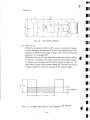
3) Power Supply
The power supply circuit is designed to provide the various power
outputs for the whole radar from nominal ship's mains for 12 VDC
T he power supply circu it consists of the switching type AVR, the
converter, the control circuit, and the rectifie r circuits.
T he basic circuit of the power supply for 12V operation is shown in
1)
I
!
I
,I
,
f
,
~.
i \.
- 37 -
Figur e 5-2.
.
L2
r '
I,
CO l
01
TR2
~
2V +
I
-
cs
1
E1
TRI
Co ntrol
~
Circuil
+
-
~
,-
T
1 I
FIG. 5·2
I--~
c.
'2
1
()
~
-:::'~
:
TR3
T1
THE BASIC CIRCUIT
(A) AVR circuit
While the transistor switch is ON, energy is sufficiently charged
into the inductor . Dur ing the OFF time, the charged energy in the
inductor is added on the supply voltage, and is fed to the load and
capa citor C5 via diode COL
While the switch is ON, the capacitor continuously feeds the power
to the load ; therefore, the output is held to the consta nt voltag e.
Volta ge across transistor swi tch Esw is shown in F igure 5-3. Its
peak value is equa l to th e outp ut voltage E2. Therefore, the supply
voltage is given by the time aver age of the outpu t voltage.
,,
Supply
I
l - --
!
I
!
Voltage~ E l
Ton-J
J
i
I
;
i
FIG. 5·3
ACROSS VOLTAGE OF THE TRANSISTOR SWITCH
I
I
i,
t
I
I...
-38-
..
•
•I
•
•o
•
•
•
•
•
•
•II
II
, II
III
J
I,
Consequently, the output voltage is described in the following
equation :
J
r
E2 = T on + T off - EI
T off
fI
(B) Converter
T R2 and TR3 ar e transistor switches, and the complementary
squarewaves are fed to TR2·B and TR3·B. T he 22KHz square
wave appears on the prima ry windings of TL The secondary
outputs of TI are fed to the rectifier circu its.
(C) Control Circuit
IC2 drives the converter T R2, T R3 and AVR control TRl.
The switching frequency is determined by C13 and RI3.
The 22KHz squarewave is superi mposed on the reference voltag e
of ICI·I4. Th is reference voltage is fed to ICI·2 and the output
voltage is ted to ICI-I via th e AVR AD] RVl. Th ese two voltages
are compared in ICI : the output pulse appears on ICI·9.
This output pulse controls the tra nsisto r switch. The regulated
output is adjusted to I6V by RVl.
(D) Rectifier Circuits
T he + 220V, + I2V and + 7V are produced in this circuit and fed
to display unit and scanner unit.
(E) HV Protection Circuit
T his circuit is provided to prevent a short circuit of the power
supply when the SCR (Mod ulator circu it) is continuously held in a
conductive conditi on.
IC3-2 triggers on a negative-going signal when HV voltage (+
220V) reaches + IOOV (voltage of IC3-2 reaches +4V). Once
triggered, the IC3-3 is held + I2V until the set time has elapsed.
T he dura tion of the set time is given by T= 1.1 x (R23) x (C20) and
is about 1 sec.. As a result , KI is OFF and the power supply circuit
and the modulator circuit are separated.
;
r
!
l
I
J,
I
I(.
t
I,
I
!
5.2.3 Receiver
1)
Micro Frontend
T he micro front end E30I contains a mixer and a local oscillat or. It
produces the IF signal (60MHz) outp ut by combining the input RF
signals and the local oscillator output frequency. Th e tuning of the
micro frontend is controlle d from the display front panel and the
display internal tune preset con trol.
-39 -
;,
II
.i,
l
..
.
!
J
2) I.F. Amplifier
The I.F. Amplifier cons ists of three amplifying stages. T he first stage
is transistor amplifier which is designed to provide a good noise
figure. The noise figure of this circuit is determined by the collector
current of the transistor, app ro ximately 3.5 rnA. The next two stages
are the integr ated circu it (lC) amp lifiers. T hese stages are contro lled
by the GAIN·STC circuit in the display unit. T he GAIN·STC control
voltage is fed to the bias terminal (5) of ICI and IC2.
GAIN·STC contro l vo ltage on J l·GS (at STC control min.) for
maximum gain is approximate ly 5V and for minimum ga in approx imately 9V.
3) Second Detector
The second detecto r is an IC detec tor which operates as a sensitive
detecto r amplifier. The negative going video signal appears across
RH , the I.F. component is removed. and the video signa l is fed to the
video circuit.
4) Video Circuit
T he emitte r follower ope ra tes as an impedance transformer to drive
the coa xial cable which feeds the video signal to the display unit.
•
- 40 -
•
•
•
•
•D
•
•
I
I
5.3 DISPLAY UNIT
I
5.3.1 Gene ral
t
All components of the display unit are mounted on the printed circuit
boards. T he display unit circuitry consists of the main control (I), main
control (2) and LCD assembly.
I
I
I
I
,I
5.3.2 Video circuit
I
,
I
I
i
~
I
f
I
f
I
r
,
f
b
•
The incoming negative going video signals is fed to the FT C (r ain
clutter) circuit. The FT C circ uit consists of a capacitor C24, a resistor
R37, and a diode CD5. The CD5 operates as a diode switch which is
contro lled by the R.CL switch on the control panel via the tra nsistor TR9.
In the "OFF" state of the rain-cl utter switch, CD5 is conductive, and the
video signals are fed to the TRIO without being differentiated. In the
"ON" state of the ra in-clutter sw itch, CD5 is not conductive and the video
signal is differentiated by C24 and R37.
The negative going outp ut of the FTC circuit is amplified by TR IO
and the inverted (positive going) output signal on the TR IO TRIO collector. Th e outpu t of the TRIO is fed to the DC restore circuit via the
emitte r follower TRll. Th e DC restore circuit consists of CD7 and
followed by TRI2.
;
'.
5.3.3 AID converter
The AID converter IC7 changes the analog video signal into a digital
pulse train and produces the negative going pulses on IC7·7. Th e digital
video output is fed to the radar control LSI IC21·15.
5.3.4 Radar control LSI
The radar control LSI IC21 consists of the buffer memory control
circuits , the STC trigger generator, transmitter trigger generator, alarm
circuit, IR circuit, EXP circuit, scan converter circuit and PPI memory
control circuit.
This IC21 is controled by CPU (IC6), the clock from the display
memory control LSI (ICI2) and the sampling clock oscillator.
5.3.5 Buffer memory (IC20)
The video pulses from IC21-18 appear at the input of the buffer
memor y (IC20-12). The displayed range (each sweep radius) is divided into
128 range cells. Therefore, the required buffer memory will be 128 bit s for
the video data of the each transmission. Two transmissions of video data
will be stored in the buffer memory for the interference rejecti on. Thi s
video data is written into the memory when the writing pulse is fed to
-41-
,
.'1
~
•
•
•
•
•
•D
•
• ••
•
•
•
•
•
•
,~
...
f.
IC20·9. The memory address da ta are inputted on AO-A8 from the radar
contr ol LSI (IC21) and the read data are fed to "PVDI" (IC21 -30).
5.3.6 Sampling clock osc illator
T he sampling clock osc illato r IC23 generates 15.5 MHz clock pulses
and is followed by the inverting buffer. Th e output of IC23·4 is fed to
IC21-16.
5.3.7 Delay circuit
IC6 is a monostable multivibr at or, given by C22, R34 and RVI. The
receiving video signa l is controlled by RV1 to display corre ct distance.
5.3.8 Transmitter trigger generato r
T he delayed T IY from lC6·13 genera tes ab out 4 microsecond pulse
at IC6. T his pulse is amplified by T R8 and drives the antenna modulator
through TR7 emitte r follower .
5.3.9 Ga in STC circuit
T he gain control voltage , OV for max , and 12V for min., is fed from
the D/ A converter (lC10·10). Its voltage is compress ed into 6V for max,
and 10V for min, with the operationa l amplifier (IC11).
Th e sea clutter control voltage. OV for min, and 12V for max ., is fed
from the D/ A converter (IC10·11). Its voltage variation is compressed into
OV for min. and 4V for max, with the operational amplifier (ICll).
When S.CL and UP ke ys are depressed. and negative going pulse
(STCT) from the radar control LSI (IC21·14) is fed to TR13-base and T R1 3
turns on. T here fore C31 will be charged up to a voltage of the lCl1-7.
After the STC T pulse is ove r, T R13 turns off and the voltage across C31
begins to discha rge via R71. T he sea clutter pulse is superimposed on the
gai n voltage throu gh the coupling cap acit or C32.
The GS output is filtered in the receicer unit and fed to the IF
amplifier.
5.3.10 Bearing pulse circuit and bearing reset circuit
T he beari ng pulse from the scanner unit is filtered by R74 and C38
and fed to the schmitt trigger IC14 and shaped into a suitable trigger pulse.
Th e lC14-12 output is then fed to IC21·33 and the CPU.
T he bea ring reset pulse from the scanner unit is filtered by R76 and
C39 and fed to lC14-11 and shaped int o a suitable reset pulse. The IC14-10
output is fed to the CPU.
.'
(I
-'-
-42 -
~
5.3.11 Address select cir cui t
The address select circuit consists of IC13 and IC14. The selection
of the read /write address for the PPI memory is carried out by this
address select circuit. The memory write address is sent from the radar
control LSI (1C21·51 to 59) and the memory read address is sent from lC8
and lC9.
t
I
5.3.12 PPI memory
The PPI memory ICI5 to lC18 store the PPI picture da ta for display
on the LCD screen. The display a rea on the LCD is divided by 200 x 240
dots. The PPI memory has 512 x 512 memory cells.
t
5.3.13 Display memory control LSI
~
,
~
T he display memory cont rol LSI (1C12) produces the PPI and
grap hic memory contro l signa l, the clock pulse for the rdar control LSI
and display timing pulses of LCD module from CPU data and 24 MHz
master clock oscillato r.
(.
f
5.3.14 Graphic memory
The graphic memory ICll is 4 x 64 K (256K) bit dynamic RAM. It
is controll ed by the GDC (IC7). All graphic dat a. graphic pattern and
characters. ar e sent from the GDC through ICI0 and stored in the graphic
memory. T he column address strobe pulse and row address strobe pulse
and write enable control pulse are fed from the display memory contro l
LSI. The graphic memory address is provided from the GDC via lC8 and
IC9.
5.3.15 0 / A converter
The D/ A converter (ICl O) produces the outputs of gain voltage, STC
voltage. LCD contrast control voltage. tune control voltage. EL brilliance
.control voltage and panel dimmer control voltage using the CPU data.
5.3.16 Tuning circuit
f
I!
II
ir,
I
The tuning circuit (IC8) pr oduces the signal for local oscillator
tuning from D/ A converter IClO-15. The RV3 is the preset tuning when
the magnetron or micr o frontend is replaced.
-43-
II
f'
I
HIGH VOLTAGE WARNING
Do not open the scanner unit when the radar is ON ; high voltages wi thin
the Scanner could be fatal to anyone coming in direct contact with it.
Disconnect ship 's power from the Scanner and Display Unit before
attempting any maintenance ; otherwise, ship's power will be present at terminals
inside the Scanner and Display Un it.
.
RADIATION HAZARD
Care should be taken to avoid possible harmful effects (particularly to the
eyes) of radiation from radar transmissions.
To avoid harmful radiation, the Display OPERA TE switch should be turned
to the STBY or OFF position when working on the Scanner. Under no circumstanced should you look directly into the antenna from a distance of less than 2
feet when the radar is in operation.
•
•
•
•II
•
• •II
•
•
•I
o
- -14 -
~
••
}
~
SECTION 6
iI
,
I
I
II I.
,
I
I
,
,
,
MAINTENANCE
6.1
GENERAL
Continuing sat isfactory operatio n of the radar can depend on how
well you ta ke care of your equipment. Th e simple maintenance tips tha t
follow can save you time, and money and help avoid premature equipment
failure.
CAUTION
When worki ng on the ra dar, make sure that the main circuit breaker
switch which supplies power to th e radar is open. As an additional
precaution, keep the POWER swi tch on the display unit in the OFF
position.
(l) Always keep the equipment as clean as possible. Use a soft cloth to
remove dirt, dust, water-spray as it appears.
(2) Periodic inspection of the radar system should include the following:
a. Check all hard ware for tightness.
b. Check for evidence of any corrosion of the scanner, display or cable
and connectors and clean as r equired.
c. Check cable connectors and terminal strip connect ors for cleanliness
and tightn ess. Make sure the wiring is free from chafing or abrasions.
-45 -
II
,
.'
6.2
SCANNER UNIT
6.2.1 Radom.
Wipe the surface of the radome with a clean, soft cloth. Check that
there is no paint. dirt or caked sa lt. A heav y deposit of dirt or caked salt
on the surface of the rad ome may cause a considerable drop in the radar
performance.
Don't use any chemical clean ers other tha n alcohol.
6.2 .2 Lubrication
Locate the ma in drive gear and clea n away old lubrication residue
and dirt.
Apply a light coating of grease (MOBILUX grease No.2 MOBIL OIL
company or equivalent) on the gear of the main shaft and drive motor.
Lubricati on shoud be done every six months.
6.2.3 Mounting
Check the mounting bolts of the scanner unit and tighten as necessary.
•J
D
•
•II
•
•
•
•D
I
-46-
•II
•
•
6.3
DISPLAY UNIT
,
!
6.3.1 Cleaning the screen
T he face of screen filter and LCD module will. in time. accumulat e
a film of conta minants which tends to dim the picture.
!
i
i
I
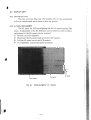
6.3.2 EL PANEL REPLACEMENT
!
The EL panel for LCD backlighting lias life of approximately 5000
hours. If adjustment of the EL brilliance control seems to have no effect ,
replacement of the EL panel may be required.
(I) Remove the LCD assembly.
(2) Disconnect the EL pane l leads from the LCD module.
(3) Pull the EL pane l out of the LCD module.
(4) T o reassemble. reverse the above procedure .
i
i
i·
i
,~."
~~
~.i
':~t
J
!j1.(
-'°t
, l'
r
EL panel
LCD module
'r.
FIG. 6·1
REPLACEMENT EL PANEL
-47 -