1
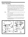
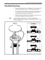
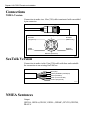
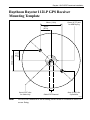
Distributed by
Any reference to Raytheon or
RTN in this manual should be
interpreted as Raymarine.
The names Raytheon and RTN
are owned by the
Raytheon Company.
Raystar 112LP
GPS Transducer
Installation Guide
Covers: E32001 SeaTalk Version
E32002 NMEA Version
Raystar 112LP GPS Transducer Installation
IMPORTANT NOTICE
This device is only an aid to navigation. Its accuracy can be affected
by many factors, including equipment failure or defects, environmental conditions and improper handling or use.
It is the user’s responsibility to exercise common prudence and
navigational judgement, and this device should not be relied upon as a
substitute for such prudence and judgement.
Package Contents
Checking your Raystar 112LP Package
The Raystar 112LP package contains the following standard items:
1. Low profile GPS receiver
2. Flush mount gasket
3. Mounting studs & Thumb nuts (x2)
4. Pole mount attachment
5. Screws (M4) for pole mount attachment (x2)
6. Installation Guide including Warranty document
Items Missing?
If any of the above items are missing or damaged, please contact your
Raytheon dealer or our Product Support Department to obtain
replacement parts. Please note that missing or damaged items
cannot be replaced without proof of purchase.
Registering this Product
Once you have checked that you have all of the listed components,
please take the time to complete the warranty document and return it
to your national distributor.
By returning this document you will receive prompt and expert
attention should you ever experience any difficulties with this product.
Also, your details are added to our customer database so that you
automatically receive new product brochures as and when they are
released.
Raystar 112LP GPS Transducer Installation
Summary of Features
Receiver type:
Frequency:
Sensitivity:
Signal acquisition:
Time to first fix:
Position accuracy:
Speed accuracy:
Geodetic Datum:
Cable length:
Operating Temp.:
Storage Temp.:
Data Input/Output:
NMEA Version
NMEA0183 V2.3 Output
Non-isolated NMEA Input
RTCM SC-104 Version 2.1 Input
SeaTalk Version
SeaTalk Bus
RTCM SC-104 Version 2.1 Input
Lithium battery (10 year life)
Memory Backup:
Disposal Note:
12 Parallel channels
1575.42 MHz +/- 1 MHz
(C/A code), L1
-130dBm
Automatic
15 minutes maximum,
typically 2 minutes
15m RMS. (L1, C/A code
HDOP <2.5 without SA)
0.5m/s RMS. (L1, C/A code
HDOP <2.5 without SA)
WGS-84
(190 alternatives programmable)
10m (33ft)
-10 to 700C (14 to 1580F)
-10 to 700C (14 to 1580F)
Care should be taken when disposing of this equipment as a Lithium
battery is fitted internally.
Local regulations may apply and must be adhered to.
Raystar 112LP GPS Transducer Installation
This page left intentionally blank
Raystar 112LP GPS Transducer Installation
Raytheon Raystar 112LP GPS Receiver
This booklet covers two models of the Raystar 112LP
SeaTalk Version
Part No. E32001
NMEA Version
Part No. E32002
Before commencing installation ensure you have the correct unit for
your application. Raytheon Marine cannot be responsible for incorrect
operation due to incorrect unit specification. Always state which
model you have when making any communication with Raytheon or a
registered service agent.
GPS Transducer Installation
The sensor is designed to receive the signals emitted from the satellites in a direct path. Ideally, the antenna unit should be mounted
horizontally in a location that is open and clear of any masts, search
lights, or other structures that could block the line-of-sight reception
of the antenna unit. The height of the GPS sensor is not as important as
the sensor having a clear view horizon to horizon for optimum signal
reception. In fact, the lower the antenna can be mounted and have a
clear view to satellites, the better. The more stable the antenna, the
easier it is to track satellites lower to the horizon.
When mounting the GPS receiver flush to a deck surface avoid areas
where the unit will be walked on or where it may become a tripping
hazard.
The GPS sensor should be separated by at least 3ft (1m) from other
communication antennas and should not be mounted in the direct path
of a Radar’s antenna beam.
While planning the location for the receiver, consider finding a
convenient pathway for running the interconnecting cable which will
connect the GPS receiver to the GPS display unit or to the rest of an
integrated system. Ideally the cable should be run in a manner so that
it can be hidden from view and, if possible, be in a direct path to the
point of connection. It is important to keep the cable separated from
other shipboard cables as much as possible to prevent interference
pick-up.
Note:
Mounting on the mast of a sailboat is not recommended
Raystar 112LP GPS Transducer Installation
Surface Mounting
1. Select a suitable area which allows access to the underside of the
mounting surface for fixing and, using the template supplied in this
document, carefully drill the two 6mm (0.25in) fixing holes marked.
2. If the cable is to pass through the mounting surface drill the 6mm
(0.25in) or 19mm (0.75”) centre hole depending on whether the plug
has to pass through the surface or not.
If the cable is to exit from the side of the GPS above the mounting
surface then remove the two plastic tabs (1) obstructing the cable
channel.
Note:
Failure to remove the plastic tabs from within the cable channel could
result in cable damage
3. Screw the supplied brass studs (2) into the underside of the receiver.
4. Stick the supplied gasket (3) to the mounting surface ensuring the
holes match and pass the cable through the centre hole or the cable
exit channel.
5. Carefully position the receiver passing the studs through the holes in
the mounting surface and secure to the mounting surface using the
thumb nuts provided (4).
1
2
3
2
3
4
4
D4190-1
Raystar 112LP GPS Transducer Installation
Pole/Rail Mounting
1. Screw the pole mount base to a suitable pole or rail mount bracket
which has an industry standard 1” 14TPI thread until secure.
2. Pass the cable through the centre hole of the pole mount base (A)
or through the cable exit hole alongside the centre hole (B) or
insert the cable into the side exit channel (C).
3. Check the cable is positioned correctly and secure the receiver to
the pole base using the two screws provided.
Note:
An optional Rail mount bracket is available from Raytheon
(Part No. D360) allowing attachment to hand/guard rails from 19mm
(3/4”) to 25mm (1in).
D4191-1
Raystar 112LP GPS Transducer Installation
Connections
NMEA Version
Connection is made via a 10m (33ft) cable terminated with a moulded
6 pin connector.
3 Screen (0V/ground)
2 Screen
(0V/ground)
4 Yellow
(NMEA out))
1 Red
(Power )
5 Green
(NMEA in)
6 Brown (RTCM in)
D4192-1
SeaTalk Version
Connection is made via the 10m (33ft) cable with bare ends suitable
for connection to an existing SeaTalk bus.
Red (12V)
Yellow (SeaTalk input/output)
Brown (RTCM in)
Green (not connected)
Screen (0V/ground)
D4193-1
NMEA Sentences
Output
GPGGA, GPGSA, GPGSV, GPGLL, GPRMC, GPVTG, GPDTM,
PRAYA.
Raystar 112LP GPS Transducer Installation
Raytheon Raystar 112LP GPS Receiver
Mounting Template
36mm (1.4in)
19mm (0.75") dia.
for NMEA plug
18mm
(0.7in)
36mm (1.4in)
18mm
(0.7in)
6mm (0.25") dia.
for cable only
Cable Exit Channel
6mm (0.25") dia.
2 positions
D4194-1
Note:
Access to the underside of the mounting surface must be available to allow for
secure fixing.
Raystar 112LP GPS Transducer Installation
This page left intentionally blank
Raystar 112LP GPS Transducer Installation
EMC Installation & Service Guidelines
All Raytheon equipment and accessories are designed to the best
industry standards for use in the leisure marine environment.
Their design and manufacture conforms to the appropriate Electromagnetic Compatibility (EMC) standards, but good installation is
required to ensure that performance is not compromised. Although
every effort has been taken to ensure that they will perform under all
conditions, it is important to understand what factors could affect the
operation of the product.
Installation
All Raytheon equipment and cables connected to it should be;
•
At least 1m (3 feet) from any equipment transmitting or cables
carrying radio signals e.g. VHF radios, cables and antennas. In the
case of SSB radios, the distance should be increased to 2m (7ft).
•
More than 2m (ft) from the path of a radar beam.
•
The equipment should be supplied from a different battery than the
one used for engine start. This will not damage the equipment, but
may cause the loss of some information and can change the operating
mode.
•
Genuine Raytheon cables should be used at all times. Cutting and
rejoining these cables can compromise EMC performance and so
should be avoided unless doing so is detailed in the installation
manual.
Check Before Going to Sea
•
Always check the installation before going to sea to make sure that it
is not affected by radio transmissions, engine starting etc...
•
In some installations, it may not be possible to prevent the equipment
from being affected by external influences. In general this will not
damage the equipment but can lead to it resetting, or momentarily
may result in faulty operation.
Servicing and Safety
•
This product contains no user servicable parts.
•
Raytheon equipment should be serviced only by authorised Raytheon
service engineers. They will ensure that service procedures and
replacement parts used will not affect performance. There are no user
serviceable parts in any Raytheon product.
•
Always report any EMC related problem to your nearest Raytheon
dealer. We will use any such information to improve our quality
standards.
Document Number: 81144-1
Raytheon Marine Company
676 Island Pond Road
Manchester, NH 03109-5420 USA
TEL (603) 647-7530
FAX (603) 634-4756
http://www.raymarine.com
Raytheon Marine Europe Ltd.
Anchorage Park, Portsmouth
Hampshire, PO3 5TD England
TEL +44 (0) 1705 693611
FAX +44 (0) 1705 694642
Printed in England