1
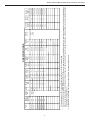
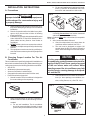
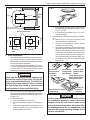
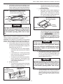
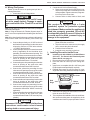
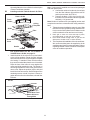
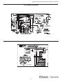
RECORD THIS UNIT INFORMATION FOR
FUTURE REFERENCE:
Model Number
Serial Number
Date Purchased
MODEL 6204XX
Roof-Top Air Conditioner
USA
SERVICE OFFICE
Dometic Corporation
2320 Industrial Parkway
Elkhart, IN 46515
574-294-2511
CANADA
Dometic Distribution
866 Langs Drive
Cambridge, Ontario
CANADA N3H 2N7
519-653-4390
For Service Center
Assistance Call:
800-544-4881
C
US
used with one of following:
3105007 Return Air Cover
3105935 Quick Cool Return Air Cover
3308120 Genesis Air Filtration System
and
3106995 Analog Wall Thermostat
THIS UNIT IS DESIGNED FOR OEM INSTALLATION
ALL INITIAL INSTALLATIONS MUST BE APPROVED BY THE SALES DEPT.
This manual must be read and understood before installation, adjustment, service, or maintenance
is performed. This unit must be installed by a qualified service technician. Modification of this product
can be extremely hazardous and
could result in personal injury or
property damage.
Models
INSTALLATION
INSTRUCTIONS
REVISION:
Form No. 3308970.015 2/05
(Replaces 3308970.007)
(French 3308971.013)
©2005 Dometic Corporation
LaGrange, IN 46761
Lire et comprendre ce manuel avant de
procéder à l'installation, à des réglages,
de l'entretien ou des réparations.
L'installation de cet appareil doit être
effectuée par un réparateur qualifié.
Toute modification de cet appareil peut
être extrêmement dangereuse et
entraîner des blessures ou dommages
matériels.
620412.331
620415.331
620415.336
620425.331
Important: These Instructions
must stay with unit.
Owner read carefully.
1
620425.336
620426.331
620426.336
620412, 620415, 620425 & 620426 Series Installation Instructions
SAFETY INSTRUCTIONS
This manual has safety information and instructions to help users eliminate or reduce the risk of
accidents and injuries.
GENERAL INFORMATION
A. Product features or specifications as described or illustrated
are subject to change without notice.
B. This Air Conditioner Is Designed For:
1. Installation on a recreational vehicle during the time
the vehicle is manufactured.
2. Mounting on the roof of a recreational vehicle.
3. Roof construction with rafters/joists on minimum of 16
inch centers.
4. Minimum of 2.00 inches and maximum of 5.50 inches
distance between roof to ceiling of recreational vehicle.
Alternate installation methods will allow for roofs more
than 5.50 inches thick.
RECOGNIZE SAFETY INFORMATION
!
C. The ability of the air conditioner to maintain the desired
inside temperature depends on the heat gain of the RV.
Some preventative measures taken by the occupants of the
RV can reduce the heat gain and improve the performance of
the air conditioner. During extremely high outdoor temperatures, the heat gain of the vehicle may be reduced by:
1. Parking the RV in a shaded area
2. Using window shades (blinds and/or curtains)
3. Keeping windows and doors shut or minimizing usage
4. Avoiding the use of heat producing appliances
This is the safety-alert symbol. When you see this
symbol in this manual, be alert to the potential for
personal injury.
Follow recommended precautions and safe operating instructions.
UNDERSTAND SIGNAL WORDS
A signal word , WARNING OR CAUTION is used
with the safety-alert symbol. They give the level of
risk for potential injury.
! WARNING indicates a potentially hazardous situation which, if not avoided, could result in
death or serious injury.
! CAUTION indicates a potentially hazardous situation which, if not avoided may result in
minor or moderate injury.
CAUTION
used without the safety alert
symbol indicates, a potentially hazardous situation which, if not avoided may result in property
damage.
Operation on High Fan/Cooling mode will give optimum or
maximum efficiency in high humidity or high outside temperatures.
Starting the air conditioner early in the morning and giving it a
"head start" on the expected high outdoor ambient will greatly
improve its ability to maintain the desired indoor temperature.
For a more permanent solution to high heat gain, accessories like
A&E outdoor patio and window awnings will reduce heat gain by
removing the direct sun. They also add a nice area to enjoy
company during the cool of the evening.
D. Condensation
Note: The manufacturer of this air conditioner will not be responsible for damage caused by condensed moisture on ceilings or
other surfaces. Air contains moisture and this moisture tends to
condense on cold surfaces. When air enters the RV, condensed
moisture may appear on the ceiling, windows, metal parts, etc.
The air conditioner removes this moisture from the air during
normal operation. Keeping doors and windows closed when this
air conditioner is in operation will minimize condensed moisture
on cold surfaces.
Read and follow all safety information and instructions.
2
13,500
15,000
620415.336
620426.331
3
1530
120VAC
60Hz.
1 Phase
1530
1530
Heater
Watts
Electrical
Rating
Amps
12.0
12.0
12.4
12.4
12.4
12.4
9.5
64.0
64.0
60.0
60.0
60.0
60.0
53.0
3.3
3.3
3.5
3.5
3.5
3.5
3.5
Compressor Compressor Fan Motor
Rated
Locked
Rated
Load
Rotor
Load
Amps
Amps
Amps
8.2
8.2
10.0
10.0
10.0
10.0
10.0
Fan Motor
Locked
Rotor
Amps
380 / 250
380 / 250
335 / 250
335 / 250
335 / 250
335 / 250
335 / 250
SCFM-High
Speed
Max./Min.
W.C.
.012 / 0.65
.012 / 0.65
.012 / 0.65
.012 / 0.65
.012 / 0.65
.012 / 0.65
.012 / 0.65
Total
Static
Max./Min.
20.0
20.0
15.2
15.2
15.2
15.2
17.0
Refrigerant
R-22
(Oz.)
SPECIFICATIONS
12 AWG
Copper
Up To 24'
Minimum
Wire Size*
20 Amp
20 Amp
20 Amp
20 Amp
20 Amp
20 Amp
20 Amp
AC Circuit
Protection
** User
Supplied
95
95
95
95
95
95
95
Installed
Weight
(Pounds)
3.5 KW/5.0 KW
3.5 KW/5.0 KW
3.5 KW/5.0 KW
3.5 KW/5.0 KW
3.5 KW/5.0 KW
3.5 KW/5.0 KW
2.5 KW/4.0 KW
Minimun
Generator
Size**
1Unit/2Units
For wire length over 24 ft., consult the National Electric Code for proper sizing.
Dometic Corporation gives GENERAL guidelines for generator requirements. These guidelines come from experiences people have had in actual applications.
When sizing the generator, the total power usage of your recreational vehicle must be considered. Keep in mind generators lose power at high altitudes
and from lack of maintenance.
*** CIRCUIT PROTECTION: Time Delay Fuse or HACR Circuit Breakers Required.
*
**
15,000
13,500
620425.331
620426.336
13,500
13,500
620415.331
620415.336
11,000
Nominal
Capacity
(BTU/HR)
Cooling
620412.331
Model
No.
620412, 620415, 620425 & 620426 Series Installation Instructions
620412, 620415, 620425 & 620426 Series Installation Instructions
b. For two unit installations: Install one Air Conditioner 1/3 and one Air Conditioner 2/3’s from
front of RV and centered from side to side.
INSTALLATION INSTRUCTIONS
A. Precautions
FIG. 2
1/2L
Improper installation may damage equipment,
could endanger life, cause serious injury and/
or property damage.
L
L
2/3L
1/3L
1. Read Installation and Operating Instructions carefully before attempting to start your air conditioner
installation.
2. Dometic Corporation will not be liable for any damages or injury incurred due to failure in following
these instructions.
3. Installation must comply with the National Electrical
Code ANSI/NFPA-70 and CSA Standard C22.1
(latest edition and any State or Local Codes or
regulations.
4. DO NOT add any devices or accessories to this air
conditioner except those specifically authorized by
Dometic.
5. This equipment must be serviced by qualified personnel and some states require these people to be
licensed.
It is preferred that the air conditioner be installed on
a relatively flat and level roof section measured
with the RV parked on a level surface.
Note: A 8° slant to either side, or front to back, is acceptable
for all units.
3. After Location Has Been Selected:
a. Check for obstructions in the area where air
conditioner will be installed. See FIG. 4.
b. The roof must be designed to support 130
pounds when the RV is in motion. Normally a
200 lb. static load design will meet this requirement.
CAUTION
B. Choosing Proper Location For The Air
Conditioner
It is the responsibility of the installer of this
air conditioner system to ensure structural integrity of the RV roof. Never create a low spot
on the roof where water will collect. Water
standing around the air conditioner may leak
into the interior causing damage to the product and the RV.
This air conditioner is specifically designed for installation on
the roof of a recreational vehicle (RV). When determining your
cooling requirements, the following should be considered:
• Size of RV;
• Window area (increases heat gain);
• Amount of insulation in walls and roof;
• Geographical location where the RV will be used;
• Personal comfort level required.
1. Normal Location-The air conditioner is designed to
fit over an existing roof vent opening.
c. Check inside the RV for return air kit obstructions (i.e. door openings, room dividers, curtains, ceiling fixtures, etc.) See FIG. 3 & 4.
FIG. 1
FIG. 3
9-1/2"
28-3/4"
39"
2. Other Locations-When no roof vent is available or
another location is desired, the following is recom-
2"
3/4"
mended:
a. For one unit installation: The air conditioner
should be mounted slightly forward of center
(front to back) and centered from side to side.
Genesis
Micro-Therm Filter System
FILTER
RESET
17"
CLEAN
FILTER
20-7/8"
17"
18-1/2"
Standard
Grill
4
620412, 620415, 620425 & 620426 Series Installation Instructions
FIG. 4
4"
FIG. 5
4"
7-1/8”
4-1/8”
REAR
OF
UNIT
21-3/8”
Center Line
of Unit
14-1/4" x 14-1/4”
(±1/8”) OPENING
7-1/8”
KEEP THESE AREAS
FREE OF OBSTRUCTIONS
d. If the opening exceeds 14-3/8" x 14-3/8", it will
be necessary to re-size the opening to 14-1/4"
x 14-1/4" (±1/8").
e. If the opening is less than 14-1/8" x 14-1/8", it
must be enlarged.
3. New Opening- (Installation Other Than Vent Opening)
a. Mark a 14-1/4" x 14-1/4" (±1/8") square on the
roof and carefully cut the opening.
b. Using the roof opening as a guide, cut the
matching hole in the ceiling.
c. The opening created must be framed to provide
adequate support and prevent air from being
drawn from the roof cavity. Lumber 3/4" or more
in thickness must be used. Remember to provide an entrance hole for power supplies, furnace wiring and a seven-conductor cable, 18 to
22 AWG is to be used for analog thermostat
connections.
12"
Air Grill Perimeter
2"
1-1/2"
F
r
o
n
t
18-1/2"
17"
1-1/4"
1-3/4"
14-1/4 x 14-1/4
(±1/8")
Opening
14-1/4 x 14-1/4
(±1/8")
Opening
3"
1-1/2"
17"
Standard
Grill
3"
R
e
a
r
2"
20-7/8"
Genesis
C. Roof Preparation
1. Opening Requirements - Before preparing the ceiling opening, the type of system options must be
decided upon. Read all of the following instructions
before beginning the installation.
If a roof vent opening will not be used a 14-1/4" x 141/4" (±1/8") opening must be cut through the roof and
ceiling of the RV. This opening must be located
between the roof reinforcing members.
FIG. 6
Do Not Cut
Roof Structure
Or Rafters
3/4" Min.
There may be electrical wiring between the
roof and the ceiling. Disconnect 120 volt AC
power cord and the positive (+) 12 volt DC terminal at the supply battery. Failure to follow
this instruction may create a shock hazard
causing death or severe personal injury.
Good-Rafters
Good LocationSupported By Between Roof
Cross Beams
Rafters
Frame Opening So It
Won't Collapse When
Bolting Down Unit
Leave Access For Power
Supply Wiring
The 14-1/4" x 14-1/4" (±1/8") opening is part of the
return air system of the Air Conditioner and must be
finished in accordance with NFPA Standard 501C
Section 2.7.2.
2. Roof Vent Removal
a. Unscrew and remove the roof vent.
b. Remove all caulking compound around opening.
c. Seal all screw holes and seams where the roof
gasket is located. Use a good grade of all
weather sealant. See FIG. 5.
15" Min. At
Front Of
Opening
CAUTION
It is the responsibility of the installer of this
air conditioner system to ensure structural
integrity of the RV roof. Never create a low
spot on the roof where water will collect. Water standing around the air conditioner may
leak into the interior causing damage to the
product and the RV.
5
620412, 620415, 620425 & 620426 Series Installation Instructions
c.
Ducts and their joints must be sealed to prevent
condensation from forming on adjacent surfaces during operation of the air conditioner.
d. Return air openings must have 40 square inches
minimum free area including the filter.
e. Return air to the air conditioner must be filtered
to prevent dirt accumulation on air conditioner
cooling surface.
5. Air Distribution System Installation
a. Dometic Corporation recommends the basic
configuration shown on page 7, for installing
this air conditioner system. We have found by
testing, that this configuration works best in
most applications of this air conditioner system. It is the responsibility of the Installer of this
system to review each RV floor plan and determine the following:
• Duct size
• Duct layout
• Register size
• Register location
• Thermostat location
4. Air Distribution System Sizing & Design
CAUTION
It is the responsibility of the installer to insure
the ductwork will not collapse or bend during
and after the installation. Dometic Corporation
will not be liable for roof structural or ceiling
damage due to improperly insulated, sealed
or collapsed ductwork.
The Installer of this air conditioner system must
design the air distribution system for their particular
application. Several requirements for this system
MUST be met for the air conditioner to operate
properly. These requirements are as follows:
a. The duct material must meet or exceed any
agency or RVIA Standard that may be in existence at the time the RV is produced.
b. All discharge air ducts must be properly insulated to prevent condensation from forming on
their surfaces or adjacent surfaces during operation of the air conditioner. This insulation
must be R-7 minimum.
AIR DISTRIBUTION
DUCT SIZING & DESIGN CHART
Return Air Cover Model
Roof Cavity Depth
Duct Cross Sectional Area
Duct Size
Depth
Width
Total Duct Length
Duct Length (short run)
3105007
3105935
2.0 In. Min. - 5-1/2 In. Max.
2.0 In. Min. - 5-1/2 In. Max.
21.0 Sq. In. Min.
32.0 Sq. In. Min.
1-1/2 In. Min. - 2-1/2 In. Max.
7.0 In. Min. - 10.0 In. Max.
15.0 Ft. Min. - 40.0 Ft. Max.
1/3 Total Duct Length
Center Duct System (Only)
Depth
Width
Total Duct Length
Duct Length (Short Run)
Register Requirements
Number Required Per Run
Register Free Air Area
Distance From Duct End
Distance From Elbow
Duct Static
Blower at High Speed,
Filter & Grill In Place
3308120
Genesis Air Filtration System
2.0 In. Min. - 2-1/2 In. Max.
8.0 In. Min. - 10.0 In. Max.
15.0 Ft. Min. - 40.0 Ft. Max.
1/3 Total Duct Length
2.0" In. Min. - 2.0" Max.
8.0 In. Min. - 8.0 In. Max.
15.0 Ft Min. - 40 Ft. Max.
1/3 Total Length
2 Min.
14.0 Sq. In.
5.0 In. Min. - 8.0 In. Max.
15.0 In.
2 Min.
14.0 Sq. In.
5.0 In. Min. - 8.0 In. Max.
15.0 In.
0.12 - 0.65 In. W.C.
0.12 - 0.65 In. W.C.
Note: Duct sizes listed are inside dimensions.
6
620412, 620415, 620425 & 620426 Series Installation Instructions
These items must be determined in conjunction with the
Air Distribution System and Sizing and Design Requirements listed in the chart on page 6. Terminate the start
of the duct at the back edge of the 14-1/4" x 14-1/4" (±1/
8"). See FIG. 7, 7A, and 7B.
Important: Alternate configurations and methods
may be used which still allow the air conditioner to
operate properly; however, these alternate configurations and methods must be approved by the Dometic
Corporation in writing. The following instructions are
based upon the use of 3105007 Dometic Return Air Kit,
3105935 Dometic Return Air Kit or 3308120 Genesis Air
Filtration System and a 3106995 Analog Thermostat.
TOP VIEW
(BACK OF RV)
FIG. 7
FRAME
DUCT
14-1/4" (±1/8”)
OPENING
AC POWER
SUPPLY WIRE
FRAME
CCC, CONTROL CABLE(S)
or 7-Wire Analog Cable
LOW VOLTAGE WIRES:
12VDC
Furnace
Load Shed
Sensors
ROOF
SIDE VIEW
(TOWARD BACK OF RV)
DUCT
14-1/4" (±1/8”)
OPENING
INSULATION
DUCT
FIG. 7A
DUCT
FRAME
CEILING
INSULATION
Duct Size And Requirements For 3105007 And 3105935 Return Air Cover
Register Required
Register Required
Short Duct Run Minimum
1/3 Total Duct Length
Total Outlet Air Area
Minimum 21.0 Sq. In.
Ducts
Depth
Width
Total Length
Min.
1-1/2”
7.0”
15.0’
Registers
4 Min.-- 8 Max.
(Per Unit)
14 Sq. In Free Area
Per Register
Max.
2-1/2”
10.0”
40.0’
Register Required
Note: Duct Size is Inside Dimensions
Roof
Rafters
Register Required
14-1/4"x14-1/4" (±1/8")
Roof Opening
FIG. 7B
Duct Size And Requirements For 33308120 Genesis Air Filtration System Kit
Register Required
Register Required
Short Duct Run Minimum
1/3 Total Duct Length
Total Outlet Air Area
Minimum 32.0 Sq. In.
Ducts
Depth
Width
Total Length
Min.
2.0”
8.0”
15.0’
Registers
4 Min.-- 8 Max.
(Per Unit)
14 Sq. In Free Area
Per Register
Max.
2-1/2”
10.0”
40.0’
Register Required
Note: Duct Size is Inside Dimensions
Roof
Rafters
7
14-1/4"x14-1/4" (±1/8")
Roof Opening
Register Required
620412, 620415, 620425 & 620426 Series Installation Instructions
d. Leave approximately 6" of cable extending
through the wall for connection to the thermostat.
e. Leave approximately 15" of cable extending into
the 14-1/4" x 14-1/4" (±1/8") opening for connection at unit.
D. Wiring Requirements
1.
Route a copper 12 AWG, with ground, 120 VAC
supply line from the time delay fuse or circuit breaker
box to the roof opening.
a. This supply line must be located in the front
portion of the 14-1/4" x 14-1/4" (±1/8") opening.
b. The power MUST be on a separate 20 Amp time
delay fuse or HACR circuit breaker.
c. Make sure that at least 15" of supply wire
extends into the roof opening. This ensures an
easy connection at the junction box.
d. Wiring must comply with all National, State and
Local Wiring Codes.
e. Use a steel sleeve and a grommet or equivalent
methods to protect the wire where it passes into
the opening.
2. Route a dedicated 12 VDC supply line (18 -22 AWG)
from the RV's converter (filtered terminals) or battery
to the roof opening.
a. This supply line must be located in the front
portion of the 14-1/4" x 14-1/4" (±1/8") opening.
b. Make sure that at least 15" of supply wire
extends into the roof opening.
3. If a furnace is to be controlled by the system, the two
furnace thermostat leads must be routed to the roof
opening. Make sure at least 15" of the furnace
thermostat wires extend into the roof opening.
4. Route a seven conductor (18 to 22 AWG) for analog
thermostat connections. Make sure 15" of the wires
extends into the roof opening and 6" extend from the
wall at the thermostat mounting location. See Section E-2.
3. Analog Thermostat Installation.
Note: Wire colors listed for the seven conductor cable are the
most common used in the RV industry. Wire Colors may
vary.
Remove the cover from the thermostat by starting at
one corner and gently lifting it from the base. Insert
the seven conductor cable through the hole in the
base assembly. Cut back the outer cable shield 3"
and strip 1/4" of insulation from the inner wires.
Mount the thermostat level on the wall using the
screws provided. See FIG. 8.
a. Connect red/white wire to the thermostat +7.5
terminal.
b. Connect the green wire to the thermostat “GND”
terminal.
c. Connect the yellow wire to the thermostat
“COOL” Terminal.
d. Connect the tan wire to the thermostat “FAN”
terminal.
e. Connect the blue wire to the thermostat “HI
FAN” terminal.
f. Connect the orange wire to the thermostat “HS/
HP” terminal (if applicable).
g. Connect the white wire to the thermostat “FUR”
terminal (if applicable).
h. Inspect connections to make sure they are tight
and not touching any other terminals or wires.
i. Push the wires back through the base into the
wall. Place cover on the thermostat and push
until an audible click is heard.
E. Analog Thermostat & Cable Installation
1. Analog Thermostat Location
The proper location of the thermostat is very important
to ensure that it will provide a comfortable RV temperature. Observe the following general rules when selecting a location:
a. Locate the Analog Thermostat 54" above the
floor.
b. Install the Analog Thermostat on a partition, not
on an outside wall.
c. Never expose it to direct heat from lamps, sun
or other heat producing items.
d. Avoid locations close to doors that lead outside, windows or adjoining outside walls.
e. Avoid locations close to supply registers and
the air from them.
f. A 3/8" diameter hole will be needed to route the
seven conductor cable through the wall. See
Section D-4.
2. Seven Conductor Cable Installation.
a. A seven-conductor cable, 18 to 22 AWG is to
be used for low voltage connections.
b. Choose the shortest, direct route from the 141/4" x 14-1/4" (±1/8") opening to the thermostat location selected.
c. Consider where screws, nails or staples might
contact the cable.
FIG. 8
HS/HP
HI FAN
+7.5
FUR
FAN
COOL
GND
Wiring
HS +7.5 COOL FUR HI FAN GND
HP
FAN
Make Sure
Connections
Are Tight And
Do Not Touch
Screw Locations
8
620412, 620415, 620425 & 620426 Series Installation Instructions
G. Installing The Air Conditioner
Installing Unit with 3105007 or 3105935 Return Air
F. Placing Air Conditioner On The Roof
1. Remove the air conditioner from the carton and discard carton. See FIG. 9.
Kit. For unit with Genesis Air Filtration System, see
page 11.
FIG. 9
FIG. 11
Divider Plate
Ceiling Template
Return Air
Cover
Return Air
Grill
This unit weighs approximately 100 pounds.
To prevent back injury, use a mechanical hoist
to place Air Conditioner on roof.
1. Installation Of Ceiling Template
a. Check gasket alignment of the air conditioner
over the roof opening and adjust if necessary.
Unit may be moved from below by slightly lifting and moving. See FIG. 11.
2. Place the air conditioner on the roof.
3. Lift and place the unit over the prepared opening using
the gasket on the unit as a guide. See FIG. 10.
FIG. 12
CAUTION
Do not slide the unit. This may damage the
roof gasket attached to the bottom and may
create a leaky installation.
Center Unit From Below
Roof
Gasket
FIG. 10
b. Remove return air cover and ceiling template
from the 3105007 or 3105935 carton.
c. Locate the four (8" x 1/4- 20) unit mounting bolts,
junction box cover and Romex connector in the
3107180 bolt kit.
d. Pull down the unit's electrical cord and fasten
the junction box with screws to the framing in
the front of the 14-1/4" x 14-1/4" (±1/8") opening. See FIG. 13.
FRONT
FIG. 13
7 Conductor
Thermostat
Cable
4. Place the Return Air Kit inside the RV. This box
contains mounting hardware for the air conditioner
and will be used inside the RV. See FIG. 9.
This completes the outside work. Minor adjustments
can be done from the inside of the RV if required.
Gasket
Pull Electrical
Cord Down
Fasten Jct. Box To
Front Of Opening
9
AC Power
Supply
620412, 620415, 620425 & 620426 Series Installation Instructions
e. Install the Romex connector in the junction box.
f. Hold the ceiling template up to the 14-1/4" x
14-1/4" (±1/8") opening. Be sure the large plate
faces the rear of the RV.
g. Start each mounting bolt through the ceiling template and up into the unit base pan by hand.
Install wood screw (not supplied) in each end
of the ceiling template. This insures a tight fit of
the return air cover to ceiling. See FIG. 14.
Evenly tighten mounting bolts to compress
gasket to 1/2" this will be a torque of 40 - 50
inch pounds. The bolts are self locking so
over tightening is not necessary. See FIG.
14.
c. Place divider plate up to bottom of air conditioner base pan firmly. The foam tape on the
divider plate must seal to bottom of base pan.
See FIG. 16.
CAUTION
Improper installation and sealing of divider
plate will cause the compressor to quick cycle
on the cold control. This may result in fuse or
circuit breaker opening and/or lack of cooling.
FIG. 16
Front of Vehicle
FIG. 14
Roof
Gasket
Screws
Tighten to
compress gasket
to 1/2"
Finger
Tight
d. With slight pressure then push the divider plate
against the double sided tape on the ceiling
template.
Note: The adhesive on the insulation is extremely sticky.
Be sure the part is located where desired before pressing
into place.
e. Locate the 1/8” x 7” x 18” self -adhesive insulation supplied with the return air kit. Remove the
backing paper from the insulation and carefully
stick onto the ceiling template divider panel.
See FIG. 17.
CAUTION
If bolts are left loose there may not be adequate roof seal or if over tightened, damage
may occur to the air conditioner base or ceiling template. Tighten to specifications listed
in this manual.
2. Installation of Divider Plate
a. Measure the ceiling to roof thickness:
• If distance is 2.0" - 3-3/4", remove perforated tab from divider plate.
• If distance is 3-3/4” - 5-1/2”, remove no tabs.
b. Remove the backing paper from double sided
tape located on ceiling template. See FIG. 15.
FIG. 17
FIG. 15
•
•
10
Excess width is intended to seal the divider plate to the sides of the 14-1/4" x 141/4" (±1/8") opening. This is to help prevent cold air discharge from circulating into
the air conditioner return air opening.
If the insulation is too high, stick excess
height of insulation to the air conditioner
base pan. Do not cover up unit rating plate.
620412, 620415, 620425 & 620426 Series Installation Instructions
Installing unit with 3308120 Genesis Air Filtration
System Return Air Kit. For unit with 3105007 or
3105935 Return Air Kit, see page 9.
FIG. 18
Base Pan
Upside
Down
Foam
Divider
Genesis Air Filtration System
Return Air Kit
Foam
Divider
Ceiling
Place Foam Divider in
(14-1/4" x 14-1/4" (±1/8")
Ceiling Opening against
Base Pan Bottom
Ceiling
Template
Slider
Filter
Foam Divider Ceiling
Level (±1/4") Tear Off
Excess
c. Install Foam Divider
• Peel the paper off of the foam divider and
stick it in place on the center of the rear
flange of the return air opening on the ceiling template. See FIG. 20.
Return Air
Cover
Grill
Handle
Do Not Peel Tape Off
Adhesive
FIG. 19
Foam Divider
FIG. 20
Micro-Therm Filter System
FILTER
RESET
CLEAN
FILTER
Adhesive
1. All Non-Center Duct Installations
Note: The Genesis Air Filtration System can be installed on
units that use a center discharge duct through the 14-1/4" x
14-1/4" (±1/8") opening. Installing units with the center discharge duct go to Section 1. "Center Discharge Duct Application Installation", on page 12.
a. Check gasket alignment of the air conditioner
over the roof opening and adjust if necessary.
Unit may be moved from below by slightly lifting and moving. See FIG. 12.
• Remove return air cover, ceiling template,
foam divider and air filter from the 3308120
carton.
• Locate the four (8" x 1/4-20) unit mounting
bolts, junction box cover and Romex connector in the 3107180 bolt kit.
• Pull down the units electrical cord and fasten the junction box with screws to the framing in the front of the 14-1/4" x 14-1/4"(±1/
8") opening. See FIG. 13.
b. Measuring Foam Divider
• Locate the foam divider and insert it corner to corner in the 14-1/4" x 14-1/4" (±1/
8") opening with the adhesive tape up (Do
not remove paper to expose adhesive). The
foam divider should be level with the ceiling
(±1/4"). Tear off the excess at the pre-cut
perforations in divider. See FIG. 19.
Peel Off Paper - Center Divider - Stick To
Rear Flange On Ceiling Template
d. Install Ceiling Template
• Start each mounting bolt through the ceiling template and up into the unit base pan
by hand. EVENLY tighten the four bolts
to a torque of 40 to 50 inch pounds. This
will compress the roof gasket to approximately 1/2". The bolts are self
locking so over tightening is not necessary.
CAUTION
If bolts are left loose there may not be adequate roof seal or if over tightened, damage
may occur to the air conditioner base or ceiling template. Tighten to specifications listed
in this manual.
11
620412, 620415, 620425 & 620426 Series Installation Instructions
e. Use Aluminum foil tape (not supplied) to seal
the ends of the foam divider to the sides of the
opening. Make sure the area behind the flange
on the ceiling template is sealed. See FIG. 20.
FIG. 20
•
Place the foam divider in the return air opening above the center duct before installing
ceiling template.
c. Install Ceiling Template
• Apply a piece of foam weather stripping (not
supplied) to the upper side of ceiling template to make a seal between it and the
duct. Use a soft piece of foam weather strip
1 x 3/4 x 10 inches. See FIG. 22.
Use Aluminum Foil Tape To Seal the
Foam Divider To The Sides of 14-1/4"
x 14-1/4" (±1/8") Ceiling Opening
Stick Weather Strip To Top
Of Ceiling Template
FIG. 22
Make Sure To Seal
Behind Flange
CAUTION
Ceiling
Template
Improper installation and sealing of foam divider will cause the compressor to quick cycle
on the cold control. This may result in fuse or
circuit breaker opening and/or lack of cooling.
Weather Strip
•
2. Center Discharge Duct Application Installation
Note: If using non-center duct installation, go to Section 1.
"All Non-Center Duct Installations", on page 11.
Important: A duct adapter (not supplied) must be installed
between the unit discharge and the customer installed center duct. This duct adapter must be approved by Dometic.
a. Check gasket alignment of the air conditioner
over the roof opening and adjust if necessary.
Unit may be moved from below by slightly lifting and moving. See FIG. 12.
• Remove return air cover, ceiling template,
foam divider and air filter from the 3308120
carton.
• Locate the four (8" x 1/4-20) unit mounting
bolts, junction box cover and Romex connector in the 3107180 bolt kit.
• Pull down the unit's electrical cord and fasten the junction box with screws to the
framing in the front of the 14-1/4" x 14-1/4"
(±1/8") opening. See FIG. 13.
b. Sizing Foam Divider
• Cut notch in the center section of the foam
divider to fit (approximately 2 x 8 inches)
snugly around duct. See FIG. 21.
FIG. 21
Foam Divider Ceiling
Level (±1/4") Tear Off
Excess
Start each mounting bolt through the ceiling template and up into the unit base pan
by hand. EVENLY tighten the four bolts
to a torque of 40 to 50 inch pounds. This
will compress the roof gasket to approximately 1/2". The bolts are self
locking so over tightening is not necessary.
CAUTION
If bolts are left loose there may not be adequate roof seal or if over tightened, damage
may occur to the air conditioner base or ceiling template. Tighten to specifications listed
in this manual.
e. Use Aluminum foil tape (not supplied) to seal
the ends of the foam divider to the sides of the
14-1/4" x 14-1/4" (±1/8") opening. Make sure
the area behind the flange on the ceiling template is sealed. See FIG. 20.
CAUTION
Improper installation and sealing of foam divider will cause the compressor to quick cycle
on the cold control. This may result in fuse or
circuit breaker opening and/or lack of cooling.
Tape Covered
Adhesive
f.
Mark And Cut 2” x 8”
Opening For Center Duct
12
Cut the opening in the center duct using the
discharge opening in the ceiling template for a
pattern. Seal the center duct to the ceiling template using foil tape, foam insulation or silicon
sealant.
620412, 620415, 620425 & 620426 Series Installation Instructions
H. Wiring The System
2. Connection Of 120 Volt Power Supply
a. Route power supply line through Romex connector into junction box on side away from the
ceiling template. Tighten connector, being careful not to pinch or short wires.
b. Connect white to white; black to black; and
Reach up into the return air opening and pull the remaining wires down.
1. Connection Of Low Voltage Wires
CAUTION
Disconnect the positive (+) 12 volt DC terminal at the supply battery. Damage to equipment could occur if the 12 volt DC is not shut
off.
This product is equipped with a 3-wire
(grounded) system for protection against
shock hazard. Make sure that the appliance is
wired into a properly grounded 120 volt AC
circuit and the polarity is correct. Failure to do
so could result in death, personal injury or
damage to the equipment.
Note: If solar panel is installed see instructions packaged
with solar panel option.
Note: If using the Genesis Air Filtration System steps "a"
and "b" are to be completed when installing the decorative
cover.
Note: Wire colors listed for the seven conductor cable are the
most common used in the RV industry. Wire Colors may
vary.
a. Connect the previously run 12 VDC to the red
and black wires protruding from the units return
air opening. Connect +12 VDC to the red wire;
–12 VDC to the black wire.
b. Connect the previously run furnace thermostat
wires (if applicable) to the blue/white wires
protruding from the units return air opening. The
polarity of these connections does not matter.
c. Connect red/white wire protruding from the units
return air opening to the seven wire cable
connected at thermostat +7.5 terminal.
d. Connect the green wire protruding from the units
return air opening to the seven wire cable
connected at thermostat “GND” terminal.
e. Connect the yellow wire protruding from the
units return air opening to the seven wire cable
connected at thermostat “COOL” Terminal.
f. Connect the tan wire protruding from the units
return air opening to the seven wire cable
connected at thermostat “FAN” terminal.
g. Connect the blue wire protruding from the units
return air opening to the seven wire cable
connected at thermostat “HI FAN” terminal.
h. Connect the orange wire protruding from the
units return air opening to the seven wire cable
connected at thermostat “HS/HP” terminal (if
applicable).
i. Connect the white wire protruding from the units
return air opening to the seven wire cable
connected at thermostat “FUR” terminal (if applicable).
green to green or bare copper wire using appropriate sized twist connectors.
c. Tape the twist wire connectors to the supply
wire to assure they don't vibrate off.
d. Push the wires into the box.
e. Install the cover onto the junction box.
I. Installing Decorative Inside Cover
Installing unit with 3105007 or 3105935 Return
1.
2.
3.
4.
Air Cover. For Genesis Air Filtration System
Return Air Kit, see page 14.
Remove the return air grill from the return air cover.
Place the return air cover up to the ceiling template.
Install cover to template with #8 x 3/8” blunt point
Phillips head screws provided (6 required).
Reinstall filter return air grill into return air cover.
Align tabs with mating notches and snap into place
FIG. 23
Hole
Plugs
5.
6.
Disconnect 120 volt AC. Failure to follow these
instructions could create a shock hazard
causing death or severe personal injury.
13
Return Air
Cover
Return
Air Grill
Install two hole plugs into screw holes in back of
return air cover. See FIG. 23.
This completes the installation of the air conditioner.
We recommend that power be supplied to the air
conditioner and check for proper operation. Refer to
620412, 620415, 620425 & 620426 Series Installation Instructions
Note: If solar panel is installed see instructions packaged
Operating Manual or Users Guide for a description
of the air conditioner operation.
Installing unit with 3308120 Genesis Air FiltraFIG. 24
with solar panel option.
a. Connect the red wire from the unit, the red wire
from the filter indicator light with the red DC
positive power lead. See FIG. 24.
b. Connect the black (-12V) wire from the unit,
the black wire from the filter indicator light with
the black (-12V) power lead.
Note: Number 10 cabinet screw (not supplied) can be used
to replace the two front screws when the ceiling material is
hard.
2. Tighten the screws holding the return air cover. Slide
the filter from the right side (looking toward the RV
front) over the filter indicator wires. Make sure the
wires are above the filter and are out of its way.
3. Place grill on return air cover and snap in place,
Genesis Air Filtration System
Return Air Kit
Foam
Divider
Ceiling
Template
Slider
Filter
and install decal on end over circuit board.
4. Place slide handle through slots in grill into the
Return Air
Cover
slide posts. Handle will fit in either direction.
5. This completes the installation of the air conditioner.
We recommend that power be supplied to the air
conditioner and check for proper operation. Refer to
Operating Manual or User’s Guide for a description
of the air conditioner operation.
Grill
Handle
Micro-Therm Filter System
FILTER
RESET
CLEAN
FILTER
tion System Return Air Kit. For 3105007 or
3105935 Return Air Kit, see page 13.
1. Install the slider in the return air cover and raise it
to the ceiling template. Route the filter indicator
wires from the return air cover through the template
slot leaving 3" extended. Place the wires where
they can be reached after plastic cover is installed.
Place the front of the return air cover against the
ceiling and slide towards the rear. The flange on
the ceiling template will catch in the groove on the
return cover. Adjust the position (right to left) and
install the front two screws. Start and tighten the
remaining screws to hold it in place. Connect together the wires from the thermostat, unit and filter
indicator.
FIG. 25
Route Wires From
Return Air Cover
Through Slot
14
620412, 620415, 620425 & 620426 Series Installation Instructions
FIELD WIRING DIAGRAM
RED
WHT
K5
BLK
BLU
BLK
BLK
COMPRESSOR
BLK
FAN
MOTOR
COM
C
G/Y
T4
RUN CAP
FAN
K4
1
YEL
CON 3
COM
BRN
WHT BLK
ELEMENT
LIMIT
SWITCH
RED
BLK
CON 2
WHT
HERM
WHT
RED
WHT
START CAP
T2
CON 1
BLK
T1
HEAT ACCESSORY
NOT AVAILABLE
ON SOME
SOLAR OR
MODELS
DIRTY FILTER
INDICATOR
IF USED
C
WHT
NO
GRN
FUSE
3
OL
S
R
T3
NO
FREEZE
CONTROL
BLU/WHT
BLU/WHT
+
TAN WHT
YEL BLU
MOTOR
STARTER
BLK
ORN RED/WHT
TO FURNACE
12V
TO LOW VOLT THERMOSTAT CABLE
15
SPLICE CAP
WHT
RED
G/Y
TO 115 VAC 60 Hz.1O
USE COPPER
CONDUCTORS
ONLY
PASSED
DIELECTRIC
3308032.071