1
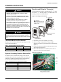
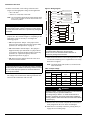
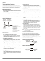
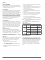
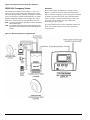
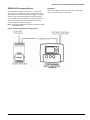
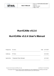
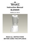
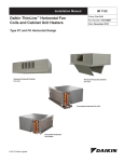
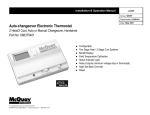
Installation and Maintenance Manual
IM-846
Group: Fan Coil
Part Number: IM 846
Date: July 2006
T170 Thermostat
24 VAC/120–277 VAC
3-Speed Fan Control (Continuous or Cycling) or Staged Fan Control
US
© 2006 McQuay International
Contents
Installation Instructions . . . . . . . . . . . . . . . . . . . . . 3
Thermostat Model and Part Number . . . . . . . . . . . . . . . . . . . . . . . . 3
Optional Occupancy Detection Sensors/Kits . . . . . . . . . . . . . . . . . . 3
Mounting and Wiring the Thermostat . . . . . . . . . . . . . . . . . . . . . . . . 3
Operation . . . . . . . . . . . . . . . . . . . . . . . . . . . . . . . . . 5
Thermostat Button Operation . . . . . . . . . . . . . . . . . . . . . . . . . . . . . .
System Button Operation . . . . . . . . . . . . . . . . . . . . . . . . . . . . .
UP/Down Arrow Button Operation . . . . . . . . . . . . . . . . . . . . . .
Fan Button Operation . . . . . . . . . . . . . . . . . . . . . . . . . . . . . . . .
Speed Button Operation (TA170-001) . . . . . . . . . . . . . . . . . . .
F/C Button Operation (TB170-001) . . . . . . . . . . . . . . . . . . . . .
Verifying Thermostat Operation . . . . . . . . . . . . . . . . . . . . . . . . . . . .
Thermostat Menu Functions. . . . . . . . . . . . . . . . . . . . . . . . . . . . . . .
Menu Function Access . . . . . . . . . . . . . . . . . . . . . . . . . . . . . . .
Menu Functions . . . . . . . . . . . . . . . . . . . . . . . . . . . . . . . . . . . .
Condensate Overflow Interrupt . . . . . . . . . . . . . . . . . . . . . . . .
5
5
5
5
5
5
5
6
6
6
6
Fan Operation . . . . . . . . . . . . . . . . . . . . . . . . . . . . . . . . . . . . . . . . .
Standard Fan Configuration (TA170-001). . . . . . . . . . . . . . . .
Staged Fan Configuration (TB170-001) . . . . . . . . . . . . . . . . .
Controlled Off Factory Configuration . . . . . . . . . . . . . . . . . . .
Fancoil Operation . . . . . . . . . . . . . . . . . . . . . . . . . . . . . . . . . . . . . .
2-Pipe Operation. . . . . . . . . . . . . . . . . . . . . . . . . . . . . . . . . . .
4-Pipe Operation. . . . . . . . . . . . . . . . . . . . . . . . . . . . . . . . . . .
Setback Operation . . . . . . . . . . . . . . . . . . . . . . . . . . . . . . . . . . . . .
7
7
7
7
8
8
8
8
Optional Occupancy Detection Equipment Operation . . . . . . . . . . . . . . . . . . . . . . . . . . . . . . . . . . 9
SB200-001 Occupancy Sensor. . . . . . . . . . . . . . . . . . . . . . . . . . . . 9
Operation . . . . . . . . . . . . . . . . . . . . . . . . . . . . . . . . . . . . . . . . 9
SD200-001 Occupancy Sensor. . . . . . . . . . . . . . . . . . . . . . . . . . . 10
Operation . . . . . . . . . . . . . . . . . . . . . . . . . . . . . . . . . . . . . . . 10
SD200-002 Occupancy Sensor. . . . . . . . . . . . . . . . . . . . . . . . . . . 11
Operation . . . . . . . . . . . . . . . . . . . . . . . . . . . . . . . . . . . . . . . 11
Installation Instructions
Installation Instructions
Mounting and Wiring the Thermostat
WARNING
• BEFORE ATTEMPTING TO INSTALL, OPERATE, OR
SERVICE THIS THERMOSTAT, CAREFULLY READ
THESE INSTRUCTIONS.
• Failure to observe safety information and comply with
instructions could result in PERSONAL INJURY, DEATH,
AND/OR PROPERTY DAMAGE.
• To avoid potential fire and/or explosion, do not use in
potentially flammable or explosive atmospheres.
• Retain these instructions for future reference. This product,
when installed, is part of an engineered system whose
specifications and performance characteristics are not
designed or controlled by McQuay. You must review your
application and national and local codes to assure that your
installation is functional and safe.
The thermostat base mounts to a field provided 4″ × 4″ outlet
box with a 2″ × 4″ mud ring (Figure 1). The thermostat cover
assembly mounts to the thermostat base.
Figure 1: Mounting the thermostat
4 × 4 outlet box
CAUTION
To avoid damaging the unit,
make all wiring connections
inside the box.
2 × 4 mud ring
DANGER
Hazardous voltage. To avoid electrical shock or damage to
equipment, disconnect power before installing or servicing.
Failure to follow these instructions will result in death or serious
injury.
Cover locking snaps
(both sides)
Base
Cover assembly
Thermostat Model and Part Number
1 Disconnect power before installing or servicing.
McQuay offers two different thermostats depending on the fan
speed control used (Table 2).
2 Run line voltage wiring (and low voltage wiring if
Table 1: Thermostat model and part numbers
Thermostat Model #
McQuay Part #
Fan Speed Control
TA170-001
107345335
3-Speed Fan Control
TB170-001
107345336
Staged Fan
Note – For a list of thermostat features, refer to ED 3611.
Optional Occupancy Detection Sensors/Kits
applicable) into the field provided outlet box and mud ring
(Figure 1).
3 Locate all connections within the mud ring/connection box
and wire nut all unused wires.
4 Remove the thermostat cover assembly from its base to
gain access to the circuit board (Figure 2).
Figure 2: Circuit board
In addition to the T170 thermostat, McQuay offers optional
occupancy detection sensors (see page 9) that can be ordered
and used in conjunction with the thermostat. When ordering,
use the associated kit number(s) provided in Table 2.
Table 2: Occupancy sensor model and kit numbers
Sensor Model #
McQuay Kit #
SA200-001
6677877211
SB200-001
6677877311
SD200-001
6677877411
SB200-002
6677877511
McQuay IM 846
3
Installation Instructions
5 On the circuit board, set the voltage selection switch
Figure 3: Wiring diagram
(Figure 2) to the appropriate voltage for the application
Setback input/door switch
White/Black
Note: The circuit board is shipped with the voltage selection switch
in the 110-227 V position. For 24 VAC use, the switch must
be in the 24 V position.
Before applying power, the voltage selection switch must be in
the appropriate position. Failure to select the correct voltage
can cause thermostat malfunction or permanently damage the
thermostat.
6 The circuit board is also equipped with configuration
jumpers (JP1, JP3, and JP4 in Figure 2). Depending on the
application, it may be necessary to reconfigure the
following jumpers:
LINE VOLTAGE
CAUTION
Accessories
available
from
McQuay
Circuit common
White/Violet
Pipe sensor
White/Blue
Occupacy detector
White/Gray
Yellow
L2/Neutral
Blue
Cool
(main output)
Red
Heat
(secondary output)
White/Brown
Fan low
White/Red
Outputs
(see ratings)
Fan medium
Fan high
White/Orange
Brown
• JP4: 2/4 Pipe Sensor Jumper - This jumper selects
between 2-pipe (jumper ON) and 4-pipe (jumper OFF)
operation (see “Fan Operation” on page 7).
• JP3: Door/Window Switch Jumper - This jumper is
shipped normally open. Placement of a jumper allows
for occupancy detection and door/window switch only
operation (see “Optional Occupancy Detection
Equipment Operation” on page 9).
Remote probe
White/Yellow
THERMOSTAT CONNECTIONS
• 110–277 V = 120, 240, or 277 VAC.
LOW VOLTAGE
• 24 V = 24 VAC
Outside air
Black
L1
CAUTION
Use copper wire only. Insulate or wire nut all unused leads.
Avoid electrostatic discharge to the thermostat.
Failure to do so can cause thermostat malfunction or
permanently damage the thermostat.
• JP1: Removal of this jumper allows the sensor to be
located in a remote location.
8 Install the thermostat base to the mud ring/outlet box using
CAUTION
Note: An output ratings chart (Table 3) is located on the
To use a remote sensor on units with local sensing capability,
remove jumper JP1 to disable local sensing. Failure to remove
JP1 can cause improper operation of the thermostat with a
remote probe installed.
7 Connect the color coded thermostat wires (Figure 3) to the
line voltage wires located in the mud ring/connection box
and secure the connections with wire nuts.
two furnished mounting screws. Tighten the screws evenly
but do not over tighten.
inside of the base.
Table 3: Output ratings
Output ratings
Voltage
Inductive
FLA
LRA
Resistive
amps
Pilot duty
HP
24 VAC
NA
NA
NA
24 VA
NA
120 VAC
5.8
34.8
6.0
125 VA
1/4
240 VAC
2.9
17.4
5.0
125 VA
1/4
277 VAC
2.4
14.4
4.2
125 VA
1/4
DANGER
Hazardous voltage. Combined load current is not to exceed 20
amps. Mount only to a grounded metallic box.
Low voltage wiring is Class 2. To avoid electrical shock or
damage to equipment, disconnect power before installing or
servicing. Failure to follow these instructions will result in death
or serious injury.
9 With the base now secured, verify that the circuit board is
firmly snapped into the cover and is not dislodged.
10 Install the cover assembly to the base, pressing firmly to
engage the cover locking snaps.
4
McQuay IM 846
Operation
Operation
Thermostat Button Operation
UP/Down Arrow Button Operation
The thermostat interface (Figure 4) contains buttons for use in
navigating to accompanying menus/screens and for performing
specific operations. These buttons and operations are described
below.
Use the Up and Down arrow buttons (Figure 4) to increase or
decrease the temperature.
Figure 4: Thermostat interface (model #TA170-001 shown)
MODES:
AUTO
UP/DOWN
ARROW
BUTTONS
COOL
HEAT
OFF
Fan Button Operation
Use the Fan button (Figure 4) to control operation of the fan.
In the ON position, the fan output operates continuously. In the
AUTO position, the output cycles with demand. In the OFF
position, all outputs are off.
Note – Model #TB170-001 (part #107345336) has staged fan
control.
Speed Button Operation (TA170-001)
The fan Speed button (Figure 4) for model #TA170-001 (part
#107345335) is determined by manually selecting HI, MED,
or LO. Press and hold the Speed button for five seconds to
toggle the displayed temperature from Fahrenheit to Celsius.
SYSTEM
BUTTON
FAN
BUTTON
SPEED
BUTTON
or
F/C
BUTTON
(part #107345336)
F/C Button Operation (TB170-001)
System Button Operation
Model #TB170-001 (part #107345336) is configured for
staged fan control and therefore utilizes a F/C button
(Figure 4) instead of a Speed button. When pressed, the F/C
button toggles between Fahrenheit and Celsius.
The System button (Figure 4) contains and displays the
following modes of operation:
Verifying Thermostat Operation
OFF—All thermostat outputs are off. The fan is still
operational if FAN ON is selected.
To verify thermostat operation after mounting and wiring it,
perform the following:
AUTO—The thermostat automatically selects heating or
cooling mode depending on the set point and room
temperature. If demand exists, the appropriate HEAT or COOL
icon illuminates. A 3°F dead band is provided to prevent short
cycling between heating and cooling modes. After changeover,
the control point automatically shifts so that the control OFF
point equals the set point temperature.
1 Energize the system.
COOL—The thermostat operates as a cooling only
thermostat.
6 Using the DOWN arrow, adjust the temperature to more
2 Set the fan to ON.
3 Select each fan speed, if available, to verify operation.
4 Set the system button to AUTO or other available selection.
5 Using the UP arrow, adjust the temperature to more than
5°F above ambient temperature to cycle on heating.
than 5°F below ambient temperature to cycle on cooling.
HEAT—The thermostat operates as a heating only thermostat.
McQuay IM 846
5
Operation
Thermostat Menu Functions
The thermostat menu contains nine functions which can be
accessed using controls on the thermostat. Accessing the menu
functions and details of each function are described below.
5 Range limit high
When this function is selected, the current maximum
temperature range adjustment, SET POINT icon, and LO
icon appear. To increase or decrease the value, press the up
or down arrow button.
6 Set back heat
Menu Function Access
1 Press and hold the UP and DOWN arrow buttons (Figure 5)
for five seconds.
2 The current display clears and the number “1” appears.
3 Press the SYSTEM button to scroll to the next item
number.
4 Use the UP and DOWN buttons to make changes within the
selected number.
Figure 5: Thermostat menu
When this function is selected, the current temperature
range adjustment, the SET BACK icon, and the HEAT icon
appear. To increase or decrease the value, press the up or
down arrow button.
7 Set back cool
When this function is selected, the current Cool setback
value, the SET BACK icon, and the COOL icon appear. To
increase or decrease the value, press the up or down arrow
button.
8 Zone temperature offset
When this function is selected, the numeric ones and tenths
(0.0) appear with a leading minus sign. To increase or
decrease the value +/– 9°F, press the up or down arrow
button. Increments are made in 1°F and 0.5°C.
Press and
Press to step
hold both for through selections
5 seconds.
(see list).
9 Keypad lockout
and
System
Temperature
adjustment
1
2
3
4
5
6
7
8
9
F/C display selecton
Continuous set point display
Fan off delay
Range limit low
Range limit high
Setback heat
Setback cool
Zone temperature offset
Keypad lockout
Menu Functions
1 F/C (Fahrenheit/Celsius) display selection
When this function is selected, the F and C icons appear
and the selected icon flashes. To toggle between F or C,
press the up or down arrow button.
2 Continuous set point display
When this function is selected, the F or C icon, current
digits, and the set point icon appear. If the Continuous set
point display is enabled, the set point icon flashes. To
toggle between continuous display of set point and display
of zone temperature, press the up or down arrow button.
3 FAN off delay
When this function is selected, the FAN, OFF, and digits
appear. The digits represent the number of seconds the fan
stays on after the heating and cooling outputs are turned
off. To increase or decrease the value from 0–255 seconds,
press the up or down arrow button.
4 Range limit low
When this function is selected, the current minimum range
setting, the SET POINT icon. and the LO icon appear. To
increase or decrease the value, press the up or down arrow
button.
6
When this function is selected, the ON and OFF icons
appear. The enabled icon flashes. OFF is the default. ON
disables the keypad except for entry into the service menu.
To increase or decrease the value, press the up or down
arrow button.
Note – In the event of a power failure, these values are stored
and can be recalled.
Condensate Overflow Interrupt
The remote probe input can be used with a condensate
overflow switch (CO), either in conjunction with a remote
probe (normally closed CO switch, Figure 6), or with local
sensing (normally open CO switch, Figure 7). When the
condensate switch activates, the thermostat displays a service
wrench icon and disables all outputs.
Figure 6: Remote probe installation
Remote probe
White/Yellow
Circuit common
White/Violet
Normally
closed
condensate
switch
Figure 7: Local sensor installation
Remote probe
White/Yellow
Circuit common
White/Violet
Normally
open
condensate
switch
McQuay IM 846
Operation
Fan Operation
The thermostat may be factory configured for standard or
staged fan operation.
Standard Fan Configuration (TA170-001)
Units with standard fan operation (Figure 8) have a selectable
fan Speed button.
Figure 8: Standard fan operation
Fan ON: fan is on continuously.
Fan AUTO: fan cycles on with demand.
S PE ED: Fan s peed is
selected by the user .
–3°F
–2°F
–1°F
1°F
Set point
–4°F
Temperature demand—cool
Temperature demand—heat
2°F
3°F
4°F
Fan AUTO: fan cycles on with demand.
Fan ON: fan is on continuously.
Staged Fan Configuration (TB170-001)
Factory configuration is available for staged fan operation
(Figure 9) to provide occupant comfort while using the most
effective fan speed.
Figure 9: Staged fan operation
Fan high
Fan medium
Fan low
Fan ON: fan stays at lowest speed.
Temperature demand—cool
Control
OFF
–5°F
–4°F
–3°F
–2°F
–1°F
System
ON
System
ON
Set 1°F
point
2°F
3°F
4°F
5°F
Temperature demand—heat
Fan ON: fan stays at lowest speed.
Fan low
Fan medium
Fan high
Controlled Off Factory Configuration
A factory configuration may be provided for minimum heating
and cooling requirements. Using this configuration, the HEAT
and COOL outputs are automatically cycled on at the heat
setback limit. Your thermostat may not have this feature.
McQuay IM 846
7
Operation
Fancoil Operation
3 If the water temperature is beyond 15°F of the set point,
Fancoil operation is either a 2-pipe or 4-pipe configuration
which is determined by jumper selection JP4 (see “Mounting
and Wiring the Thermostat” on page 3).
4 If the water temperature is not beyond 15°F of the set point,
normal HVAC control occurs.
the thermostat checks to see if the water temperature is
above 80°F or below 60°F.
2-Pipe Operation
If yes, normal HVAC control occurs.
In this configuration, the thermostat permanently disables the
secondary output and disables the fan from cycling in an
invalid mode. The main output configuration is dependent on
the pipe sensor input. With a pipe sensor connected, the
thermostat automatically selects heating or cooling depending
on the sensed water temperature. If the pipe sensor input is
open (unconnected), the main output only cools. If the pipe
sensor input is shorted, the main output only heats. Normal
thermostat default is for 4-pipe operation. For 2-pipe
operation, install a jumper on JP4.
If no, the thermostat opens the main output (COOL) for
three minutes.
4-Pipe Operation
In this configuration, both the main output (COOL) and the
secondary output (HEAT) are available. These both cycle ON
depending on the mode of the thermostat. With a pipe sensor
connected, the thermostat automatically changes the main
output to heat and disables the secondary output if the main
coil water is hot. For 4-pipe operation, the JP4 jumper is
removed.
Pipe Sensor Operation
A pipe sensor can be connected when the thermostat is
configured for either 2-pipe or 4-pipe configuration. The pipe
sensor is used to determine the water temperature in the main
coil, which should be connected to the primary output.
Pipe sensor input—use a 10K Remote Probe or a standard ONOff Aquastat for summer/winter changeover.
Purge Cycle
With a pipe sensor connected, the thermostat initiates a purge
cycle if the sensed water temperature is ambiguous (not
adequately hot or cold). The sequence for purge cycle
operation is as follows:
1 The thermostat has a call for heat or cooling.
Note: If at any time the call goes away, the thermostat
stops the purge cycle.
5 After the three minute purge cycle occurs, the thermostat
checks to see if the water temperature is more than 15°F
from the set point, or above 80°F, or below 60°F.
If yes, normal HVAC operation occurs.
If no, the valve is left open and the thermostat continues to
search for a valid reading.
Note – If at any time the demand goes away, the thermostat will
stop the purge cycle.
Table 4 shows output operation, depending on the sensed
water temperature.
Table 4: Output operation
2-Pipe/4-Pipe
Water
selection
temperature
Cold
2-pipe
JP4 ON
Hot
Cold
4-pipe
JP4 OFF
Hot
Output operation
Secondary
Main output
output
Cooling only
The fan does not cycle on
Disabled
with a heat demand.
Heating only
The fan does not cycle on
Disabled
with a cool demand.
Cooling
Heating
Heating only
The fan does not cycle on
Disabled
with a cool demand.
Setback Operation
In this configuration, the low level switch input normally is
open. To enable setback operation, the JP3 jumper is removed
(see “Mounting and Wiring the Thermostat” on page 3). The
input will close and the thermostat heating and cooling setback
limits can then be used as temperature control points. Fan
operation in setback is cycled with demand. Press any
thermostat key to override setback for one hour. Setback
overrides any user setting except if the control is turned to
OFF.
2 The thermostat checks the pipe sensor to verify water
temperature.
8
McQuay IM 846
Optional Occupancy Detection Equipment Operation
Optional Occupancy Detection Equipment Operation
The T170 thermostat can be used with optional S200 series
occupancy detection equipment. Purchasing and installing this
equipment to compliment the thermostat adds energy savings
by setting back HVAC operation during occupied and
unoccupied times. Optional detection equipment
configurations and operation are described below.
SB200-001 Occupancy Sensor
The SB200-001 occupancy sensor (Figure 10) serves as an
occupancy sensor for automatic control of a guest room HVAC
system. It incorporates an innovative dual delay processor
which allows the sensor to verify the nature of occupancies,
and is capable of eliminating unnecessary actuations of the
HVAC device due to unintentional passages or short time
occupancies. The sensor may also serve as a slave sensor
(Figure 11 on page 10).
The sensor switch is open in occupied mode and closed in
unoccupied mode. An optional door and/or window switch
(Figure 10) is open when the door/window is open and is
closed when the door/window is closed.
Note – To use this configuration, a jumper must be installed to
JP3 to allow occupancy input.
Note – An optional door and/or window switch (Figure 10) can be
added for use with the SB200-001 sensor.
Operation
In an occupied mode, the thermostat operates normally and
looks for a door open signal. When the door opens, the
thermostat waits for a door close signal. If the door is open for
more than two minutes, the thermostat turns the HVAC system
outputs to OFF. During this two minute period, if any button is
pressed on the keypad, the time delay is extended to ten
minutes. The time delay can only be extended once. Once the
HVAC outputs transition to OFF, a door closure is required to
re-enable the outputs. When the door closes, the thermostat
starts a two minute timer and tries to detect occupancy. If the
timer expires and no occupancy is detected, the thermostat
transitions to an unoccupied state. If occupancy is detected
while the timer is running, the thermostat will remain in the
occupied mode.
In an unoccupied mode, the thermostat sets heating and
cooling set points to setback values as determined by factory
or user settings. The fan is automatically set to cycle with
demand. The thermostat continually monitors the occupancy
sensor and will enter into occupied mode if occupancy is
detected.
If the installation is only using a door/window switch, the
thermostat will disable the HVAC outputs if this output is open
for longer than two minutes.
To enable door/window switch only operation, install a jumper
to JP3 (see “Mounting and Wiring the Thermostat” on page 3)
and the occupancy input must be shorted to circuit common.
Figure 10: Optional equipment configuration #1
McQuay IM 846
9
Optional Occupancy Detection Equipment Operation
SD200-001 Occupancy Sensor
Operation
The SD200-001 occupancy sensor (Figure 11) serves as a
master sensor for a guest room HVAC management system.
The sensor provides HVAC operation according to occupancy
status, as well as door/window switch monitoring, selectable
high/low temperature setback, form-C output, slave sensor
connectivity, and a five minute door open HVAC shut-off.
In an occupied mode, the SD200-001 occupancy sensor
(Figure 11) and door switch use advanced microprocessor
logic to determine occupancy. A door open signal will initiate
occupancy status detection. If the sensor determines that a
room is occupied, it will allow normal HVAC control. The
sensor will wait for another door open signal before
determining occupancy again.
Note – To use this configuration, the jumper to JP3 is removed to
allow setback input.
Note – An optional door and/or window switch (Figure 11) and
slave sensor can be added for use with the SD200-001
sensor.
In an unoccupied mode, the sensor continually monitors the
room. Any occupancy detection will set the operation to
occupied mode.
Figure 11: Optional equipment configuration #2
10
McQuay IM 846
Optional Occupancy Detection Equipment Operation
SD200-002 Occupancy Sensor
Operation
The SD200-002 occupancy sensor serves as a stand alone
master sensor for a guest room HVAC management system.
The sensor provides HVAC operation according to occupancy
status, as well as selectable high/low temperature setback,
form-C output, and a five minute door open HVAC shut-off.
This system provides basic room setback and is ideal for
control of HVAC in commercial spaces.
With each occupancy detection, an OFF delay is started and
can be set to delay for up to 30 minutes.
Note – To use this configuration, the jumper to JP3 is removed to
allow setback input.
Figure 12: Optional equipment configuration #3
McQuay IM 846
11
McQuay Training and Development
Now that you have made an investment in modern, efficient McQuay equipment, its care should be a high priority.
For training information on all McQuay HVAC products, please visit us at www.mcquay.com and click on training, or
call 540-248-9646 and ask for the Training Department.
Warranty
All McQuay equipment is sold pursuant to its standard terms and conditions of sale, including Limited Product
Warranty. Consult your local McQuay Representative for warranty details. Refer to Form 933-43285Y. To find your
local McQuay Representative, go to www.mcquay.com.
This document contains the most current product information as of this printing. For the most up-to-date product
information, please go to www.mcquay.com.
© 2006 McQuay International • www.mcquay.com • 800-432-1342