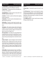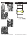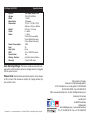
1
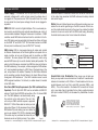
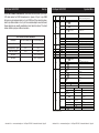
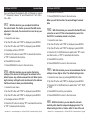
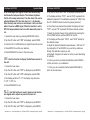
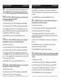
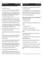
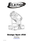
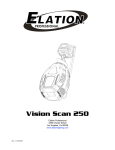
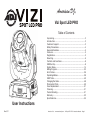
American DJ
®
Vizi Spot LED PRO
Table of Contents
User Instructions
Rev. 8/11
Unpacking......................................................................3
Introduction....................................................................3
Customer Support......................................................................3
Safety Precautions......................................................................4
General Information.....................................................................5
Features.........................................................................5
Registration......................................................................5
Mounting.........................................................................6
Controls and Functions..............................................................8
DMX Set-Up................................................................................8
System Menu............................................................................14
Editing Program.........................................................................33
Error Codes...............................................................................36
Operating Modes.......................................................................38
DMX Traits.................................................................................40
Changing the Gobo...................................................................48
Photometric Chart.....................................................................50
Fuse Replacement....................................................................51
Cleaning..................................................................51
Trouble Shooting.......................................................................51
Warranty.................................................................52
Specifications....................................................................55
American DJ® - www.americandj.com - Vizi Spot LED PRO - Instruction Manual - Page 2
Vizi Spot LED PRO Introduction
Unpacking: Thank you for purchasing the Vizi Spot LED PRO by
American DJ®. Every Vizi Spot LED PRO has been thoroughly tested
and has been shipped in perfect operating condition. Carefully check
the shipping carton for damage that may have occurred during shipping. If the carton appears to be damaged, carefully inspect your fixture for any damage and be sure all equipment necessary to operate
the unit has arrived intact. In the event damage has been found or parts
are missing, please contact our toll free customer support number for
further instructions. Please do not return this unit to your dealer without contacting customer support first.
Introduction: The Vizi Spot LED PRO is a compact, bright, moving
head, DMX intelligent fixture. The Vizi Spot LED PRO can be either a
10 or 12 Channel DMX unit. The fixture can operate in three different
operating modes; show mode, sound-active, or under DMX Control.
The Vizi Spot LED PRO can be used as a stand alone unit or in a
master/slave configuration. For best results use fog or special effects
smoke to enhance the beams projections.
Customer Support: American DJ® provides a toll free customer
support line, to provide help and to answer any question should you
encounter problems during your set up or initial operation. You may
also visit us on the web at www.americandj.com for any comments or
suggestions. Service Hours are Monday through Friday 8:00 a.m. to
4:30 p.m. Pacific Standard Time.
Voice:
(800) 322-6337
Fax: (323) 582-2941
E-mail: [email protected]
To purchase parts online visit http://parts.americandj.com
Warning! To prevent or reduce the risk of electrical shock or fire, do
not expose this unit to rain or moisture.
Warning! This may cause severe eye damage. Avoid looking directly
into the light source at all times!
American DJ® - www.americandj.com - Vizi Spot LED PRO - Instruction Manual - Page 3
Vizi Spot LED PRO Safety Precautions
For Your Own Personal Safety, Please Read and Understand This
Manual Completely Before You Attempt To Install Or Operate
This Unit!
•To reduce the risk of electrical shock or fire, do not expose this unit rain or moisture
•Do not spill water or other liquids into or on to your unit.
•Do not attempt to operate this unit if the power cord has been
frayed or broken.
•Do not attempt to remove or break off the ground prong from the electrical cord. This prong is used to reduce the risk of electrical shock and fire in case of an internal short.
•Disconnect from main power before making any type of connection.
• Do not remove the cover under any conditions. There are no user serviceable parts inside.
•Never operate this unit when it’s cover is removed.
•Always be sure to mount this unit in an area that will allow proper ventilation. Allow about 6” (15cm) between this device and a wall.
•Do not attempt to operate this unit, if it becomes damaged.
•This unit is intended for indoor use only, use of this product outdoors voids all warranties.
•Always mount this unit in safe and stable matter.
•Power-supply cords should be routed so that they are not likely to be walked on or pinched by items placed upon or against them, paying particular attention to cords at plugs, convenience recep-
tacles, and the point where they exit from the appliance.
• Cleaning -The fixture should be cleaned only as recommended by the manufacturer. See page 48 for cleaning details.
•Heat -This fixture should be situated away from heat sources such
as radiators, heat registers, stoves, or other appliances (including
amplifiers) that produce heat.
•The fixture should be serviced by qualified service personnel when:
A. Objects have fallen, or liquid has been spilled into the appliance.
B. The appliance has been exposed to rain or water.
C. The appliance does not appear to operate normally or exhibits a marked change in performance.
American DJ® - www.americandj.com - Vizi Spot LED PRO - Instruction Manual - Page 4
Vizi Spot LED PRO
General Information
Vizi Spot LED PRO Mounting
To optimize the performance of this product, please read these operating
instructions carefully to familiarize yourself with the basic operations of
this unit. These instructions contain important safety information regarding the use and maintenance of this unit. Please keep this manual with
the unit, for future reference.
When installing the unit, the trussing or area of installation must be
able to hold 10 times the weight without any deformation. When
installing the unit must be secured with a secondary safety attachment, e.g. and appropriate safety cable. Never stand directly below
the unit when mounting, removing, or servicing the unit.
American DJ® will not accept any liability for any resulting damages
caused by the non-observance of this manual or any unauthorized
modification to this unit.
Overhead mounting requires extensive experience, including calculating working load limits, installation material being used, and perodic
safety inspection of all installation material and unit. If you lack these
qualifications, do not attempt the installation yourself.
Caution! There are no user serviceable parts inside this unit. Do not
attempt any repairs yourself, doing so will void your manufactures warranty. In the unlikely event your unit may require service please contact
American DJ®.
Vizi Spot LED PRO These installaiton should be checked by a skilled person once a year.
Features
• DMX-512 Protocol Compatible (Uses either 12 or 14 DMX Channels)
• 3 Operating Modes - Sound Active, Show Mode, DMX Control
• Internal Microphone
• Edit and Save Scenes into the Memory
• Variable Strobe (1-12 fps)
• Switchable 540˚ to 630˚ Pan Movement
• 270˚ Tilt Movement
• Digital Display for Address and Function Setting
Vizi Spot LED PRO Product Registration
The Vizi Spot LED PRO carries a three year (1095 days) limited warranty. Please fill out the enclosed warranty card to validate your
purchase. All returned service items whether under warranty or not,
must be freight pre-paid and accompany a return authorization (R.A.)
number. The R.A. number must be clearly written on the outside of
the return package. A brief description of the problem as well as the
R.A. number must also be written down on a piece of paper and included in the shipping carton. If the unit is under warranty, you must
provide a copy of your proof of purchase invoice. You may obtain a
R.A. number by contacting our customer support team on our toll free
customer support number. All packages returned to the service department not displaying a R.A. number on the outside of the package
will be returned to the shipper at the shippers cost.
American DJ® - www.americandj.com - Vizi Spot LED PRO - Instruction Manual - Page 5
The Vizi Spot LED PRO is fully operational in two different mounting
positions, hanging upside-down from a ceiling or set on a flat level
surface. To avoid internal damage to the unit, never mount the unit on
its side as illustrated above. Be sure this fixture is kept at least 0.5m
away from any flammable materials (decoration etc.). Always use
and install the supplied safety cable as a safety measure to prevent
accidental damage and/or injury in the event the clamp fails (see next
page). Never use the carrying handles for secondary attachment.
American DJ® - www.americandj.com - Vizi Spot LED PRO - Instruction Manual - Page 6
Vizi Spot LED PRO Mounting
NOTICE: The suitable enviromental temperature for this lighting fixture is between -25˚ C to 45˚ C. Do not place this lighting
fixture in an enviroment where the temperatures are under or
above the temperatures stated above. This will allow the fixture
to run at its best and help prolong the fixture life.
Vizi Spot LED PRO
Controls and Functions
FRONT
REAR
Screw one clamp each via a M12 screw and nut onto the
Omega holders. Insert the quick-lock fasteners of the first
Omega holder into the respective holes on the bottom of the
Vizi Spot LED PRO. Tighten the quick-lock fasteners fully clockwise. Install the second Omega holder. Pull the safety-cable
through the holes on the bottom of the base and over the trussing system or a safe fixation spot. Insert the end in the carabine
and tighten the safety screw.
American DJ® - www.americandj.com - Vizi Spot LED PRO - Instruction Manual - Page 7
American DJ® - www.americandj.com - Vizi Spot LED PRO - Instruction Manual - Page 8
Vizi Spot LED PRO Controls and Functions
1.Lens Assembly - This high quality lens can be focused in DMX
mode. Please see pages 44-51 for DMX values and functions.
2. Digital Display - This display shows the menu and operating functions that you can choose from.
3. Mode/ESC Button - This button is used to exit menus and to scroll
backwards through certain menus only.
4. Up Button - This button is used to scroll forward when navigating
through the system menu.
5. Down Button - This button is used to scroll backwards when navigating through the system menu.
Vizi Spot LED PRO Controls and Functions
technician.
11. Power Switch - This switches the power to the fixutre “On” and
“Off”.
12. XLR Output Jack - This jack is used to transmit the incoming
DMX s ignal to another DMX fixture, or transmit a Master/Slave signal
to the next Vizi Spot LED PRO in the chain. For best results in DMX or
Master/Slave mode terminate this jack if it is the last unit in the chain.
See “Terminator” on page 11.
13.XLR DMX Input Jack - This jack is used to receive an incoming
DMX s ignal or Master/Slave signal.
6. Enter Button - This button is used to select and confirm a function when working in the system menu. It is also used to exit certain
menus.
7. Microphone - This microphone receives external low frequencies
to trigger the unit in Sound-Active mode. This microphone is designed
to receive low frequency sounds only, tapping on the microphone and
high pitch sounds may not trigger the unit.
8. Carrying Handles - The includes built-in carrying handles. Be sure
to always handle the unit by the built-in handles. Never lift or carrying the unit by head or yoke. Pulling on or transporting the unit by the
moving head may severely damage the unit and will void the unit warranty.
9. Power Cord Inlet - This cord is designed to match the electrical
requirements of the unit. Voltage may vary from venue to venue, when
connecting this unit to a power supply be sure to connect to a matching power outlet. Never use this fixture if the ground prong has been
removed or broken off. The ground prong is designed to reduce the
risk of fire or electrical shock in the event the unit suffers from an internal short.
10. Fuse Holder - The fuse housing stores a 2 amp (1 amp 220v) protective fuse. Never defeat the fuse, the fuse is designed to protect the
electronics in the event of severe power fluctuations. Always be sure
to replace the fuse with an exact match as the one being replaced,
unless otherwise told to do so by an authorized American DJ® service
American DJ® - www.americandj.com - Vizi Spot LED PRO - Instruction Manual - Page 9
American DJ® - www.americandj.com - Vizi Spot LED PRO - Instruction Manual - Page 10
REMOTE
CONTROL
INPUT
SOUND
Vizi Spot LED PRO
Set Up
OUTPUT
2
3
American DJ® - www.americandj.com - Vizi Spot LED PRO - Instruction Manual - Page 11
Set Up
POWER
COMMON
DMX512 OUT
3-PIN XLR
1
2
DMX +
3
DMX -
3
1
DMX512 IN
3-PIN XLR
2
3
1
2
Figure 2
XLR Female Socket
XLR Male Socket
1 Ground
2 Cold
2 Cold
REMOTE
CONTROL
INPUT
SOUND
INPUT
OUTPUT
1 Ground
XLR Pin Configuration
Pin 1 = Ground
REMOTE
CONTROL
SOUND
3 Hot
INPUT
OUTPUT
Pin 2INPUT
= Data Compliment (negative)
3 Hot
Pin 3 = Data True (positive)
Figure 3
Special Note: Line Termination. When longer runs of cable are
POWER
POWER
used, you may need to use a terminator on the last unit to avoid erratic
behavior. A terminator is a 90-120 ohm 1/4 watt resistor which is connected between pins 2 and 3 of a male XLR connector (DATA + and
DATA -). This unit is inserted in the female XLR connector of the last
unit in your daisy chain to terminate the line. Using a cable terminator
(ADJ part number Z-DMX/T) will decrease the possibilities of erratic
behavior.
DMX+,DMX-,COMMON
1
SOUN
DMX+,DMX-,COMMON
cables. Do not use
the ground lug on the XLR connector. Do not connect the cable’s shield conductor to the ground lug or allow the shield
conductor to come in contact with the XLR’s outer casing. Grounding
the shield could cause a short circuit and erratic behavior.
POWER
Data Cable (DMX Cable) Requirements (For DMX and Master/Slave
Operation): The Vizi Spot LED PRO can be controlled via DMX-512
protocol. The Vizi Spot LED PRO can be either a 12 or 14 channel DMX
unit. The DMX address is set electronically using
the controls on the side panel of the unit. Your
COMMON
DMX +
unit and your DMX controller require a approved
DMX512 OUT
3-PIN XLR
DMX DMX-512 110 Ohm Data cable for data input and
data output (Figure 1). We recommend Accu-Cable
DMX cables. If you are making your own cables, be
sure to use standard 110-120 Ohm shielded cable
(This cable may be purchased at almost all proFigure 1
fessional sound and lighting stores). Your cables
OUTPUT
Notice: Be sure to follow
figures two and three when making your own
DMX512
tocol used by most lighting and controller manufactures as a form of
communication between intelligent fixtures and controllers. A DMX
controller sends DMX data instructions from the controller to the fixture. DMX data is sent as serial data that travels from fixture to fixture
via the DATA “IN” and DATA “OUT” XLR terminals located on all DMX
fixtures (most controllers only have a DATA “OUT” terminal).
INPUT
INPUT
POWER
DMX-512: DMX is short for Digital Multiplex. This is a universal pro-
REMOTE
CONTROL
INPUT
REMOTE
CONTROL
INPUT
SOUND
should be made with a male and female XLR connector on either end
of the cable. Also remember that DMX cable must be daisy chained
and cannot be split.
automatic voltage switch, which will auto sense the voltage when it
is plugged into the power source. With this switch there is no need
to worry about the correct power voltage, this unit can be plugged in
anywhere.
SOUND
OUTPUT
Vizi Spot LED PRO
Power Supply: The American DJ® Vizi Spot LED PRO contains a
DMX Linking: DMX is a language allowing all makes and models
of different manufactures to be linked together and operate from a
single controller, as long as all fixtures and the controller are DMX
compliant. To ensure proper DMX data transmission, when using
several DMX fixtures try to use the shortest cable path possible. The
order in which fixtures are connected in a DMX line does not influence
the DMX addressing. For example; a fixture assigned a DMX address
of 1 may be placed anywhere in a DMX line, at the beginning, at the
end, or anywhere in the middle. Therefore, the first fixture controlled
by the controller could be the last fixture in the chain. When a fixture
is assigned a DMX address of 1, the DMX controller knows to send
DATA assigned to address 1 to that unit, no matter where it is located
DMX512
in the DMX chain.
INPUT
3
1
2
DMX512 IN
3-PIN XLR
3
1
2
Termination reduces signal errors and
avoids signal transmission problems
and interference. It is always advisable
to connect a DMX terminal, (Resistance
120 Ohm 1/4 W) between PIN 2 (DMX-)
and PIN 3 (DMX +) of the last fixture.
Figure 4
American DJ® - www.americandj.com - Vizi Spot LED PRO - Instruction Manual - Page 12
Termination
avoids sign
and interfere
to connect a
120 Ohm 1/4
and PIN 3 (
Vizi Spot LED PRO
Set Up
Vizi Spot LED PRO
5-Pin XLR DMX Connectors. Some manufactures use 5-pin DMX-
512 data cables for DATA transmission in place of 3-pin. 5-pin DMX
fixtures may be implemented in a 3-pin DMX line. When inserting standard 5-pin data cables in to a 3-pin line a cable adaptor must be used,
these adaptors are readily available at most electric stores. The chart
below details a proper cable conversion.
0
ADDR
1
TEST
2
PLAY
AXXX A001
T-01~T-XX
RUN
MSTR/ALON
AUDI
MSTR/ALON
AUTO
Clos/Hold/Auto/Audi
ALL
3-Pin XLR to 5-Pin XLR Conversion
Conductor
3-Pin XLR Female (Out)
5-Pin XLR Male (In)
Ground/Shield
Pin 1
Pin 1
Data Compliment (- signal)
Pin 2
Pin 2
Data True (+ signal)
Pin 3
Pin 3
Not Used
Pin 4 - Do Not Use
Not Used
Pin 5 - Do Not Use
3
RESE
4
TIME
5
6
7
8
9
RPAN
RTLT
FINE
DEGR
MIC
SCAN
COLR
GOBO
OTHR
LIFE
CLMP
ON/OFF
ON/OFF
ON/OFF
540/630
M-XX M-70
VALU
10
DISP
D ON
FLIP
LOCK
RDMX
SPOT
DFSE
11
SPEC
FEED
FANS
HIbE
VER
ADJU
SEPR
STEP
12
EDIT
SCXX
REC.
RUN
Default settings shaded
American DJ® - www.americandj.com - Vizi Spot LED PRO - Instruction Manual - Page 13
System Menu
Indicate the staring DMX address
A001 also is the setting for slave
Automatically test the function
Runs fixture as “master” or “alone” for
auto
Runs fixture as “master” or “alone” for
audio
No DMX Status
Reset all motors and returns fixture to
home
Reset only motors for pan/tilt
Reset only motors for colors
Reset only motors for gobo and rotation
Reset other motors
0000~9999
Displays the total fixture running time
Clear lamp running time
Reverses the pan movements
Reverses the tilt movements
Switch 16 bit/8 bit
Pan degree select
Mic sensitivity
Display the DMX512 value of each
D–XX D-00 (DXXX)
channel
ON/OFF
Display turn off after 2mins
This function will reverse the display
ON/OFF
180
ON/OFF
Key lock
Change DMX address via external
ON/OFF
controller
ON/OFF
Lamp optimization
Resets all the fixture functions to
ON/OFF
default
Pan/tilt feedback (error correction)
ON/OFF
on/off
AUTO/HIGH/LOW
Fan’s mode select
OFF/1-99M 15M
Stand by mode
V1.0~V9.9
Software version
CODE
CXXX
Fixture code *code is “C050”
CH01~CHXX
XXXX(-128~127)
Motor Fix
AUTO
Select program to be edit
IP01~IP07
Set the amount of your
S–01 ~S–48
program
Edit the channels of each
C–01~C–XX
XXX(0~255)
scene
TIME
T XXX(001~999)
Time for each scene
CEDT
ON/OFF
Edit program via controller
RE.XX
Auto Save
Program test
ON/OFF
American DJ® - www.americandj.com - Vizi Spot LED PRO - Instruction Manual - Page 14
Vizi Spot LED PRO
System Menu
ADDRESS MENU AOO1 - A511 (Value) - This is where you set the DMX address of
the unit.
TEST MENU T-01 - T-XX (Test) - Tests the functions of each channel.
Note: Some channels cannot be tested.
PLAY MENU RUN - Runs the unit as a “master” or in a stand alone mode. The
unit will run a internal program mode.
AUDI (Audio) - Runs the unit as a “master” or in a stand alone,
sound active mode.
AUTO - This is a precaution mode in case the DMX signal is lost.
There are four settings to choose from:
• “Hold” - This is the default setting, which in case the signal is
lost the fixute will “hold” at the last setting.
Vizi Spot LED PRO
System Menu
RPAN (REVERSE PAN) MENU ON/OFF - When “On” is chosen it will reverse the pan.
RTILT (REVERSE TILT) MENU ON/OFF - When “On” is chosen it will reverse the tilt.
FINE MENU ON/OFF - Switch between 8bit (coarse) and 16bit (fine) pan & tilt
movement. This also switches the DMX channel mode between
10 channel (8 bit) and 12 channel (16 bit) DMX mode.
DEGR MENU 540/630 - Switch the degree of the Pan between 630 and 540.
MIC MENU M-01-M-70 - With this function you can make the internal mic
more or less sensitive to sound.
• “Close” - The fixture will return to its “home” standing.
DISPLAY MENU VALU (DMX-512 Value) - Display the DMX-512 value of each
channel.
• “Auto” - The fixture will go into Auto mode and run a pre-programmed show.
D ON - Display will turn off in 2 minutes.
• “Audi” - The fixture will go into Sound Active mode.
FLIP - “Flips” the digital display 180º.
LOCK - When activated the buttons will lock automatically. See
page 25 for more information.
RESE (RESET) MENU ALL - Resets all the motors in the unit.
SCAN - Resets the motors that control pan/tilt.
COLR (Color) - Resets the color motors.
GOBO - Resets the gobo motors.
OTHR - Resets all other motors.
TIME MENU LIFE - Displays the fixtures total running time.
CLMP - Clears the fixture running time.
American DJ® - www.americandj.com - Vizi Spot LED PRO - Instruction Manual - Page 15
SPEC MENU RDMX - Lets you adjust the DMX address via external controller.
SPOT - This provides a spot beam for better lamp optimization.
DFSE (Default Settings) - Resets the unit to the default settings.
FEED - Pan/Tilt feedback (error correction) on/off.
FANS - Select the fan running mode.
HIBE - This feature will automatically shut down the lamp and
stepping motors. Please see pages 28-29.
American DJ® - www.americandj.com - Vizi Spot LED PRO - Instruction Manual - Page 16
Vizi Spot LED PRO
VER (Version) - Displays the software version
System Menu
ADJU - Calibration functions
EDIT MENU SEPR (AUTO IP01 - IP07) - Lets you edit any of the 7 internal
programs.
STEP (S-01 - S-48) - These are the steps slots that you write
your programs into. There are at total of 48 steps. See edit program.
SCXX (SC01 - SC30) - These are the scenes that are stored in your program. There are a total of 30 scenes.
REC - This will auto save your custom program.
RUN - This will run your custom program.
Vizi Spot LED PRO
System Menu
On-Board System Menu. The Vizi Spot LED PRO ccomes with an
easy to navigate system menu. This next section will detail the functions of each command in the system menu.
To access the main menu press the MODE/ESC button (3) on the front
of the unit. Tap the UP (4) or DOWN (5) butons until you reach function
you wish to change. When you reach the function you wish to change
tap the ENTER button. Again, tap the UP or DOWN buttons to change
the function. Once your changes are made, tap the ENTER button to
lock the change in the system, if the ENTER button is not selected
within eight seconds the system will automatically return to menu section. To exit without making any changes tap the MODE/ESC button.
ADDR MAIN MENU -
ADDR
DMX Address Setting via control board -
1. Access the main menu.
2. Tap the UP button until “ADDR” is displayed, press ENTER.
4. Now the display will show “A001”. Adjust the DMX address
by pressing the UP or DOWN buttons.
5. Press ENTER to confirm.
6. Press the MODE/ESC button to return to the main menu.
When the display is on “A001”, you can directly press the UP
or DN buttons to change the DMX start address.
TEST MAIN MENU -
TEST - This will test the functions of each channel.
1. Access the main menu.
2. Tap the UP button until “TEST” is displayed, press ENTER.
3. The display will show “T-01”. You can now press the up
button and test the different channels.
American DJ® - www.americandj.com - Vizi Spot LED PRO - Instruction Manual - Page 17
American DJ® - www.americandj.com - Vizi Spot LED PRO - Instruction Manual - Page 18
Vizi Spot LED PRO
4. Press MODE/ESC to exit.
System Menu
Vizi Spot LED PRO
System Menu
“AUDI”. “HOLD” is the default setting.
PLAY MAIN MENU -
5. Select the mode that you want the fixture to run in case of a
lost DMX signal and press ENTER.
Master/Slave configuration, or as a stand alone unit -
RESE MAIN MENU -
RUN Run the unit in an Auto mode as a “master” in a
1. Access the main menu.
2. Tap the UP button until “PLAY” is displayed, press ENTER.
ALL - When you activate the reset function, the fixture will
begin the reset motion, reseting all motors.
3. Tap the UP button until “RUN” is displayed, press ENTER.
1. Access the main menu.
4. Tap the UP or DOWN button to choose between “MSTR” or
“ALON“, select your choice by pressing ENTER, “PASS” will flash
in the display and fixture will begin its function.
3. Tap the UP button until “ALL” is displayed.
AUDI
Run the unit in Sound Active mode as a “master”, or
as a stand alone unit 1. Access the main menu.
2. Tap the UP button until “PLAY” is displayed, press ENTER.
2. Tap the UP button until “RESE” is displayed, press ENTER.
4. Press ENTER to reset all motors, or press MODE/ESC to
cancel and return to the main menu.
SCAN - When you activate this reset function, the fixture
will only reset the pan/tilt motor.
1. Access the main menu.
3. Tap the UP button until “AUDI” is displayed, press ENTER.
2. Tap the UP button until “RESE” is displayed, press ENTER.
4. Tap the UP or DOWN button to choose between “MSTR” or
“ALON“, select your choice by pressing ENTER, “PASS” will flash
in the display and fixture will begin its function.
3. Tap the UP button until “SCAN” is displayed.
AUTO
This is a precaution mode in case you lose the DMX
signal. The fixtue has 4 modes to choose from, please see
page 15 for a description of the 4 modes 1. Access the main menu by pressing MODE/ESC button.
2. Tap the UP button until “PLAY” is displayed, press ENTER.
3. Tap the UP button until “AUTO” is displayed, press ENTER.
4. Now you can choose between “CLOSE”, “HOLD” “AUTO”, or
American DJ® - www.americandj.com - Vizi Spot LED PRO - Instruction Manual - Page 19
4. Press ENTER to reset the pan/tilt motors, or press MODE/
ESC to cancel and return to the main menu.
COLR - When you activate this reset function, the fixture
will only reset the color wheel motor.
1. Access the main menu by pressing MODE/ESC button.
2. Tap the UP button until “RESE” is displayed, press ENTER.
3. Tap the UP button until “COLR” is displayed.
4. Press ENTER to reset the color wheel motor, or press MODE/
American DJ® - www.americandj.com - Vizi Spot LED PRO - Instruction Manual - Page 20
Vizi Spot LED PRO
System Menu
Vizi Spot LED PRO
System Menu
ESC to cancel and return to the main menu.
CLMT - With this function you can clear the running time of
GOBO - When you activate this reset function, the fixture
1. Access the main menu.
will only reset the gobo wheel motor.
1. Access the main menu by pressing MODE/ESC button.
2. Tap the UP button until “RESE” is displayed, press ENTER.
3. Tap the UP button until “GOBO” is displayed.
4. Press ENTER to reset the gobo wheel motor, or press MODE/
ESC to cancel and return to the main menu.
OTHR - When you activate this reset function, the fixture
will reset all other motors that are not listed in RESET
menu.
1. Access the main menu by pressing MODE/ESC button.
2. Tap the UP button until “RESE” is displayed, press ENTER.
3. Tap the UP button until “OTHR” is displayed.
4. Press ENTER to reset all other motors, or press MODE/ESC
to cancel and return to the main menu.
TIME MAIN MENU -
LIFE - With this function you can display the total running
time of the unit.
1. Access the main menu.
the unit.
2. Tap the UP button until “TIME” is displayed, press ENTER.
3. Tap the UP button until “CLMT” is displayed, press ENTER.
4. Press ENTER to confirm.
5. Press MODE/ESC to return to the main menu.
RPAN MENU -
RPAN - The movement of the Pan will be reversed.
1. Access the main menu.
2. Tap the UP button until “RPAN” is displayed, press ENTER.
3. Press the UP or DOWN buttons to select either “ON” to activate this function, or “OFF” to deactivate this function.
4. Press ENTER to confirm.
5. Press MODE/ESC to return to the main menu.
RTLT MENU -
RTLT - The movement of the Tilt will be reversed.
1. Access the main menu.
2. Tap the UP button until “RTLT” is displayed, press ENTER.
2. Tap the UP button until “TIME” is displayed, press ENTER.
3. Press the UP or DOWN buttons to select either “ON” to activate this function, or “OFF” to deactivate this function.
3. Tap the UP button until “LIFE” is displayed, press ENTER.
4. Press ENTER to confirm.
4. Press MODE/ESC to return to the main menu.
5. Press MODE/ESC to return to the main menu.
American DJ® - www.americandj.com - Vizi Spot LED PRO - Instruction Manual - Page 21
©American
DJ® - www.americandj.com - Vizi Spot LED PRO - Instruction Manual - Page 22
Vizi Spot LED PRO
System Menu
Vizi Spot LED PRO
System Menu
3. Tap the UP button until “MIC” is displayed, press ENTER.
FINE MENU -
4. The display will show “M-01”.
tilt movement. This also switches the DMX Channel mode
between 12 channel (8 bit) and 14 channel (16 bit) DMX
mode.
6. Press ENTER to confirm when you have reached your
desired microphone sesitivity level.
FINE - Switch between 8bit (coarse) and 16bit (fine) pan &
1. Access the main menu.
3. Tap the UP button until “FINE” is displayed, press ENTER.
4. Press the UP or DOWN buttons to select either “ON” (14
Channel Mode) to activate this function, or “OFF” (12 Channel
Mode) to deactivate this function.
5. Press ENTER to confirm.
6. Press MODE/ESC to return to the main menu.
DEGR MENU -
DEGR - With this function you can switch the Pan degree.
1. Access the main menu.
2. Tap the UP button until “DEGR” is displayed, press ENTER.
3. Press the UP or DOWN buttons to select either “630” or
“540”.
4. Press ENTER to confirm your selection.
5. Press the UP or DOWN button to adjust the microphone sensitivity between “M-01 - M-99”.
7. Press MODE/ESC to return to the main menu.
DISP MAIN MENU -
VALU
Display the DMX-512 value of each channel -
1. Access the main menu.
2. Tap the UP button until “DISP” is displayed, press ENTER.
3. Tap the UP button until “VALU” is displayed, press ENTER.
4. The display should show “D-00”. Press the UP button in
order to select the desired channel. If you select “D-05” the
display will only show the DMX value of the 5th channel
5. Press ENTER to confirm.
6. Press MODE/ESC to return to the main menu.
Now the display will change as per the 5th channel DMX
value.
5. Press MODE/ESC to return to the main menu.
D ON
MIC MENU -
1. Access the main menu.
MIC - The internal microphone can be made more or less
sensitive.
With this function “On” the display will shut off after
2 minutes 2. Tap the UP button until “DISP” is displayed, press ENTER.
1. Access the main menu.
American DJ® - www.americandj.com - Vizi Spot LED PRO - Instruction Manual - Page 23
American DJ® - www.americandj.com - Vizi Spot LED PRO - Instruction Manual - Page 24
Vizi Spot LED PRO
System Menu
3. Tap the UP button until “D ON” is displayed, press ENTER.
4. Press the UP or DOWN buttons to select either “ON” to activate this function, or “OFF” to deactivate this function.
5. Press ENTER to confirm.
6. Press MODE/ESC to return to the main menu.
FLIP - This function will reverse the display 180º.
1. Access the main menu.
2. Tap the UP button until “DISP” is displayed.
3. Tap the UP button until “FLIP” is displayed, press ENTER.
4. Press the UP or DOWN buttons to select either “ON” to activate this function, or “OFF” to deactivate this function.
5. Press ENTER to confirm.
6. Press MODE/ESC to return to the main menu.
LOCK - With this function you can activate the automatic
button lock. When this function is activated, the buttons
will automatically lock 15 seconds after the last press of
a button. In order to deactivate the button lock, press the
MODE/ESC button for 3 seconds.
1. Access the main menu.
2. Tap the UP button until “DISP” is displayed.
3. Tap the UP button until “LOCK” is displayed, press ENTER.
4. Press the UP or DOWN buttons to select either “ON” to activate this function, or “OFF” to deactivate this function.
5. Press ENTER to confirm.
6. Press MODE/ESC to return to the main menu.
American DJ® - www.americandj.com - Vizi Spot LED PRO - Instruction Manual - Page 25
Vizi Spot LED PRO
System Menu
SPEC MAIN MENU -
RDMX
With this function you are able to change the DMX
address via any DMX controller. This function is factory set
to “ON” already.
1. Access the main menu by pressing MODE/ESC.
2. Tap the UP button until “SPEC” is displayed, press ENTER.
3. Tap the UP button until “RDNX” is displayed, press ENTER.
4. Press the UP button to select “ON” to activate this function,
or “OFF” to deactivate.
5. Press ENTER to confirm, and “PASS” will flash quickly.
6. Press MODE/ESC to return to the main menu.
To use this function follow the instructions:
To adjust the address of your unit you must first go to the
address that it is currently set to. From there you can adjust the
address. First make sure all channels are set to the value of “0”.
1. On your DMX controller set the DMX value of Channel 1 to
the value “7”.
2. Now set the DMX value of Channel 2 to the value “7” to
adjust the starting address between 1 and 255. To adjust the
address between 256 and 511 set Channel 2 to the value “8” .
3. Set the DMX value of Channel 3 to your desired starting address. This will take about 20 seconds before the unit
accepts the new DMX address.
EXAMPLE: So, if you want the address to be 57, you must first
set the address that is currently assingned to the unit. The proceed to set Channel 1s’ value to “7”, Channel 2s’ value to “7”,
and Channel 3s’ value to “57”.
2ND EXAMPLE: Again, if you want the address to be 420, you
must first set the address that is currently assingned to the unit.
American DJ® - www.americandj.com - Vizi Spot LED PRO - Instruction Manual - Page 26
Vizi Spot LED PRO
System Menu
Vizi Spot LED PRO
If you want the set the address to 420, set Channel 1s’ value to
“7”, Channel 2s’ value to “8”, and Channel 3s to “164”. (256 +
164 = 420)
6. Press ENTER to confirm.
SPOT
- With this function you can adjust the LED via
the control board. The shutter opens and the LED can be
adjusted. In this mode, the device will not react to any control signal.
1. Access the main menu.
2. Tap the UP button until “SPEC” is displayed, press ENTER.
3. Tap the UP button until “SPOT” is displayed, press ENTER.
4. The display will show “ON/OFF”.
5. Press the UP button to select “ON” to activate this function,
or “OFF” to deactivate this function.
6. Press ENTER to confirm.
7. Press MODE/ESC to return to the main menu.
DFSE - With this function you can restore the factory
settings of the device. All settings will be set back to the
default values. Any edited scenes will be lost. When restoring the factory settings the unit must be set to the address
that the unit was in when you started editing.
1. Access the main menu.
2. Tap the UP button until “SPEC” is displayed, press ENTER.
3. Tap the UP button until “DFSE” is displayed, press ENTER.
4. The display will show “ON/OFF”.
5. Press the UP button to display “ON” to activate this function,
or “OFF” to deactivate this function.
American DJ® - www.americandj.com - Vizi Spot LED PRO - Instruction Manual - Page 27
System Menu
7. Press MODE/ESC to return to the main menu.
When you exit this function, the unit will begin to reload
data.
FEED
- With this function you can switch the Pan/Tilt error
correction on and off. This will automatically correct the
Pan/Tilt if it is somehow moved out of place.
1. Access the main menu.
2. Tap the UP button until “SPEC” is displayed, press ENTER.
3. Tap the UP button until “FEED” is displayed, press ENTER.
4. Press the UP or DOWN buttons to select either “ON” to activate this function, or “OFF” to deactivate this function.
5. Press ENTER to confirm.
6. Press MODE/ESC to return to the main menu.
FANS - With this function you can choose between the fan
settings of Low, High or Auto. The default setting is Auto.
1. Access the main menu by pressing MODE/ESC button.
2. Tap the UP button until “FANS” is displayed, press ENTER.
3. Press the UP or DOWN buttons to select either “LOW”, “HIGH”,
or “AUTO”.
4. Press ENTER to confirm your selection.
5. Press MODE/ESC to return to the main menu.
HIBE - With this function you can make the unit auto-
matically shut down the lamp and stepping motors. The
default setting for this is 15 mins. After 15 mins if the unit
American DJ® - www.americandj.com - Vizi Spot LED PRO - Instruction Manual - Page 28
Vizi Spot LED PRO
System Menu
is not receiving a DMX signal, the unit will automatically
shut down the lamp and motors. This feature lengthens
the life of the lamp and motors. The shut down time can be
adjusted between OFF (no shut down) or 1 - 99 minutes.
Once the lamp and motors are shut down, it will reset itself
when it receives a DMX signal. When the function is set to
OFF, the lamp and motors will not shut down until power is
cut.
1. Access the main menu by pressing MODE/ESC button.
2. Tap the UP button until “HIBE” is displayed, press ENTER.
3. Press the UP or DOWN buttons to adjust the shut down time.
4. Press ENTER to confirm your selection.
5. Press MODE/ESC to return to the main menu.
VER - Use this function to display the Software version of
the unit.
1. Access the main menu.
2. Tap the UP button until “SPEC” is displayed, press ENTER.
3. Tap the UP button until “VER” is displayed, press ENTER.
Vizi Spot LED PRO
System Menu
4. Tap the UP button until “CODE” is displayed, press ENTER.
5. The display will show “CXXX”, were as “XXX” represents the
calibration password. The calibration password is “C050.” Use
the UP or DOWN buttons to enter the proper password.
6. Once the proper password is entered the display will read
“CHXX”, were as “XX” represents the fixture channel number,.
7. Select the desired channel to be calibrated by pressing the
UP or DOWN buttons and then ENTER to confirm.
8. The display will then read “XXXX”, were “XXXX” stands for
the calibrate values.
9. Adjust the desired calibration value between –128 and 127
by pressing the UP and DOWN. As you scroll up and down
through the calibration values you will
notice slight changes in the wheel or motor you are attempting
to calibrate.
10. Once you reach your desired calibration press ENTER to
confirm and lock in your calibration.
11. Once you are completely finished press MODE/ESC to
return to the main menu.
4. The display will show “V-1.0”, the display may also show,
“V-2.0”, “V-9.9” etc.
5. Press MODE/ESC to exit.
ADJU - Use this function is used to make sure all motors
are aligned and to adjust any motors that are not.
1. Access the main menu.
2. Tap the UP button until “SPEC” is displayed, press ENTER.
3. Tap the UP button until “ADJU” is displayed, press ENTER.
American DJ® - www.americandj.com - Vizi Spot LED PRO - Instruction Manual - Page 29
American DJ® - www.americandj.com - Vizi Spot LED PRO - Instruction Manual - Page 30
Vizi Spot LED PRO
System Menu
EDIT - This menu item allows you to write a program into the
memory (EEPROM) via the control panel or via the external
controller. Please see pages 32-34 for detailed instructions.
SEPR (IP01-IP07) - With this function you can edit any of
the internal programs (IP01-IP07).
1. Access the main menu.
2. Tap the UP button until “EDIT” is displayed, press ENTER.
3. Tap the UP button until “SEPR” is displayed, press ENTER.
4. The display will show “IPXX”. “XX” represeting 01-07. Tap
the UP of DOWN buttons to find your desired program to edit.
Press ENTER to edit the chosen program.
5. Press ENTER to save and press MODE/ESC to exit.
STEP (S-01 - S-48) - With this function you can program
the number of steps in your individual Program.
1. Access the main menu.
2. Tap the UP button until “EDIT” is displayed, press ENTER.
Vizi Spot LED PRO
4. The display shows “SC01”, this stands for the first scene of
your program. You can call up to 48 scenes. For example, if
“SC05”, it means that “Run” will run the first 5 scenes you saved
in “Edit”.
5. Press ENTER to save and press MODE/ESC to exit.
REC - With this function you can record the scenes automatically for the external controller.
1. Access the main menu.
2. Tap the UP button until “EDIT” is displayed, press ENTER.
3. Tap the UP button until “REC” is displayed.
4. The display shows “RE.XX”, “XX” stands for the scene
number in the internal memory of where your scenes from the
controller will be stored.
5. Press the UP or DOWN button to select your desired scene
number.
6. Press ENTER to confirm, and the fixture will record the
scenes from the external controller.
3. Tap the UP button until “STEP” is displayed, press ENTER.
7. Press MODE/ESC to return to the main menu.
4. The display shows “S-01”, this stands for the first step of
your program. You can call up to 48 scenes in “Run”. For example, if “S-05” is displayed, it means that “Run” will run the first
5 scenes you saved in “Edit”.
RUN
5. Press ENTER to save and press MODE/ESC to exit.
SCXX (SC01 - SC48) - With this function you can choose
the number of scenes in your Program.
1. Access the main menu.
2. Tap the UP button until “EDIT” is displayed, press ENTER.
3. Tap the UP button until “SC01” is displayed.
American DJ® - www.americandj.com - Vizi Spot LED PRO - Instruction Manual - Page 31
System Menu
With the function “RUN”, you can run your pre-made
program. You can set the number of steps under Step (S-01
- S-48).
1. Access the main menu.
2. Tap the UP button until “EDIT” is displayed, press ENTER.
3. Tap the UP button until “RUN” is displayed, press ENTER.
4. Press either UP or DOWN, to select “ON” or “OFF”. To run
your program select “On” and press ENTER to confirm.
5. Press MODE/ESC to return to the main menu.
American DJ® - www.americandj.com - Vizi Spot LED PRO - Instruction Manual - Page 32
Vizi Spot LED PRO
Editing Program
Editing procedure 1: Using the control board only.
1. Access the main menu.
2. Tap the UP button until “EDIT” is displayed. Press ENTER.
3. The display will show “SCXX”, the “X” again stands for the
scene number. For example, “SC01” is displayed, it means you
will be editing scene 1, press ENTER. You can change the
scene number by pressing the UP button.
4. Press ENTER, the display will show “C-X”, the “X” again
stands for the channel number. If “C-01” is displayed, you will
be editing channel 1 of your selected scene, press ENTER. You
can change the channel number by pressing the UP button.
5. The display will show the DMX value for the channel that is
being edited. It will be displayed as “11XX”, it stands for Channel
11 of the editing scene, the DMX value is “XX”.
6. Adjust the DMX value by pressing the UP button, until you
get the expected effect for this channel.
7. Press ENTER to enter the editing of the other channels of the
scene.
8. Repeat steps 5-8, until you finish setting all the DMX values
for all the channels of this scene, each scene can have 15
channels maximum.
9. Once all the channels are completed, the display will flash
“TIME”, this stands for the time needed to run this scene.
10. Press ENTER to edit the time needed, the display shows
“TXXX”, “X” stands for the time needed to run this scene. For
example, “T002” means scene 1 needs 0.4 seconds to run,
“T015” means scene 1 needs 3 seconds to run.
11. Adjust the time needed by pressing the UP button.
12. Press ENTER to save the settings for the scene you are
editing, the display will change to the next scene automatically.
American DJ® - www.americandj.com - Vizi Spot LED PRO - Instruction Manual - Page 33
Vizi Spot LED PRO
Editing Program
13. Repeat steps 3-12 to edit other scenes, you can edit and
save 48 scenes maximum.
14. Press MODE/ESC to exit, now you have edited and saved
scenes using the control board. The number of steps can be
defined under “Step” and the scenes can be called up under
“Run”. To run the scenes see page 31.
Editing procedure 2: Using an external controller (Manually
record scenes one by one):
1. Access the main menu.
2. Select “EDIT” by pressing the UP or DOWN buttons, press
ENTER.
3. The display shows “SC01”.
4. Press ENTER, and the display shows “C-01”.
5. Select “CEDT” by pressing the DOWN button, and press
ENTER.
6. The display “OFF”, press the UP button so that “ON” is displayed, and press ENTER.
7. The display will show “SCO2”. You have now successfully
downloaded the first scene.
8. Adjust the Step-time needed by pressing the UP button.
9. Call up the second scene in your controller now.
10. Repeat steps 7-9 until all desired scenes are downloaded.
11. Press MODE/ESC to exit. The number of steps can be
defined under “Step” and the scenes can be called up under
“Run”.
American DJ® - www.americandj.com - Vizi Spot LED PRO - Instruction Manual - Page 34
Vizi Spot LED PRO
Editing Program
Editing procedure 3: Record the selected scenes automatically from external controller:
1. Access the main menu.
2. Select “EDIT” by pressing the UP or DOWN buttons, press
ENTER.
3. Press the UP button until the display shows “STEP”, press
ENTER.
4. Now adjust and set the number of steps by pressing the
UP or DOWN buttons. Press ENTER to confirm the number of
steps, and “PASS” will display briefly.
5. Now press the DOWN button until “REC” is displayed, and
press ENTER.
6. The display will now show “RE.XX”, “XX” stands for the scene
number in the internal memory which the scenes from the controller will be stored to. Press ENTER when you have chosen
the scene number.
7. Call up the scenes on the controller, and the fixture will
record the scenes from the controller automatically. After the
number of scenes as selected in the “STEP” menu are loaded
into the fixture, it will stop the procedure and return to the previous menu.
8. Press MODE/ESC to exit the “EDIT” menu and return to the
main menu.
Vizi Spot LED PRO
Error Codes
When power is applied, the unit will automatically enter a
“reset/test” mode. This mode brings all the internal motors to a
home position. If there is an internal problem with one or more
of the motors an error code will flash in the display in the form
of “XXer”, “XX” will represent a function number. For example,
when the display shows “03Er,” it means there is some type of
error with the channel 3 motor. If there are multiple errors during
the start-up process they will all flash in the display. For example: if the fixtures has errors on channel 1 and channel 3 all at
the same time, you will see the error message flash “01Er”, and
“03Er repeated 5 times.
If an error does occur during the initial start-up procedure the
fixture will self-generate a second reset signal and try to realign
all the motors and correct the errors, if the errors persist after a
second attempt a third attempt will be made.
If after a third attempt all the errors have not been corrected the
fixture will make the following determinations:
1) 3 or more errors - The fixture cannot function properly with
three or more errors therefore the fixture will place itself in a
stand-by mode until subsequent repairs can be made.
2) Less than 3 errors - If the fixture has less than 3 errors, therefore most other functions will work properly. The fixture will
attempt to operate normally until the errors can be corrected by
a technician. The errors in question will remain flashing in the
display as a reminder of internal errors.
01Er – PAN movement error:
This message will appear after a fixture reset, if the pan-yoke’s
magnetic-indexing circuit malfunctions (sensor failed or magnet
is missing) or there is a stepper motor failure (defective motor
or a defective motor IC drive on the main PCB).
03Er – TILT movement error:
This message will appear after a fixture reset, if the tilt magnetic-indexing circuit malfunctions (sensor failed or magnet is
American DJ® - www.americandj.com - Vizi Spot LED PRO - Instruction Manual - Page 35
American DJ® - www.americandj.com - Vizi Spot LED PRO - Instruction Manual - Page 36
Vizi Spot LED PRO
Error Codes
missing) or there is a stepper motor failure (defective motor or a
defective motor IC drive on the main PCB).
05Er – COLOR WHEEL error:
This message will appear after a fixture reset, if the head’s magnetic-indexing circuit malfunctions (sensor failed or magnet is
missing) or there is a stepper motor failure (defective motor or a
defective motor IC drive on the main PCB).
06Er – ROTATING GOBOS error:
This message will appear after a fixture reset, if the magneticindexing circuit malfunctions (sensor failed or magnet is missing) or there is a stepper motor failure (defective motor or a
defective motor IC drive on the main PCB).
07Er – GOBO ROTATING error:
This message will appear after a fixture reset, if the magneticindexing circuit malfunctions (sensor failed or magnet is missing) or there is a stepper motor failure (defective motor or a
defective motor IC drive on the main PCB).
08Er – PRISM error:
This message will appear after a fixture reset, if the magneticindexing circuit malfunctions (sensor failed or magnet is missing) or there is a stepper motor failure (defective motor or a
defective motor IC drive on the main PCB).
10Er – FOCUS error:
This message will appear after a fixture reset, if the magneticindexing circuit malfunctions (sensor failed or magnet is missing) or there is a stepper motor failure (defective motor or a
defective motor IC drive on the main PCB).
Vizi Spot LED PRO
Operation
Operating Modes: The Vizi Spot LED PRO can operate in three
different modes. This next section will detail the differences in
the operating modes.
• Stand alone mode The unit will react to sound, or chase through the built-in programs.
• Master/Slave mode You can daisy chain up to 16 units together to get a synchronized
light show without the need of an external controller. The units will
react to sound or chase through the built-in programs.
• DMX control mode This function will allow you to control each individual fixtures traits
with a standard DMX-512 controller such as the Elation ® Show
Designer.™
Universal DMX Control: This function allows you to use a uni-
versal DMX-512 controller such as the Elation® DMX Operator™ or
Elation® Show Designer™ to control head movement, the color wheel,
gobo wheel, prism, and the shutter (strobe). A DMX controller allows
you to create unique programs tailored to your individual needs.
1. The Vizi Spot LED PRO has a 12 channel DMX mode and 14 channel DMX mode. To select your desired DMX mode please
see page 23 “FINE” menu See pages 39-44 for detailed descrip-
tion of the DMX traits.
2. To control your fixture in DMX mode, follow the set-up procedures
on pages 10-12 as well as the set-up specifications that are
included with your DMX controller.
3. Use the controller’s faders to control the various DMX fixture traits.
4. This will allow you to create your own programs.
5. Follow the instruction on page 18 to set the DMX address.
6. For longer cable runs (more than a 100 feet) use a terminator on the last fixture.
7. For help operating in DMX mode consult the manual included with your DMX controller.
Stand-Alone (Sound Active or Auto Program): This mode allows
a single unit to run to the beat of the music or run through a built-in
program.
1. Access the main menu.
American DJ® - www.americandj.com - Vizi Spot LED PRO - Instruction Manual - Page 37
American DJ® - www.americandj.com - Vizi Spot LED PRO - Instruction Manual - Page 38
Vizi Spot LED PRO
Operation
2. Tap the UP button until “PLAY” is displayed, and Press ENTER.
3. Tap the UP button until “AUTO” is displayed, and Press ENTER.
4. Press UP, to select “OFF”, “RUN”, or “AUDI”. “RUN” will make the unit run through a built-in program. “AUDI” will make the unit sound active.
5. Select a mode, and press ENTER to confirm.
6. Press MODE/ESC if you want to return to the main menu.
7. You may change the show or invert the pan and tilt functions in the system menu by following the directions on page 22.
Vizi Spot LED PRO Channel
1
2
3
4
5
Master-Slave Operation (Sound Active or Auto Program):
This function will allow you to link up to 16 units together and operate without a controller. The units can run a built-in program or run in
sound actiive mode. In Master-Slave operation one unit will act as the
controlling unit and the others will react to the controlling units programs. Any unit can act as a Master or as a Slave.
1. Using standard XLR data cables, daisy chain your units together via the XLR connector on the rear of the units. Remember the Male XLR connector is the input and the Female XLR connector is the output. The first unit in the chain (master) will use the female XLR connector only - The last unit in the chain will use the male XLR connector only. For longer cable runs we suggest a termina-
tor at the last fixture.
2. Access the main menu.
2. Tap the UP button until “PLAY” is displayed, and Press ENTER.
3. Tap the UP button to choose between “RUN” or “AUDI”. “RUN” will make the units run through a built-in program. “AUDI” will make the units sound active.
4. Press UP, to select “ALON” or “NAST”. Which means stand alone, or master/slave mode.
5. Select a mode, and press ENTER to confirm.
6. Press MODE/ESC if you want to return to the main menu
7. You may change the show or invert the pan and tilt functions in the system menu by following the directions on page 22.
American DJ® - www.americandj.com - Vizi Spot LED PRO - Instruction Manual - Page 39
Value
0 - 255
0 - 255
0 - 255
0 - 255
0 - 14
15 - 29
30 - 44
45 - 59
60 - 74
75 - 89
90 - 104
105 - 119
120 - 127
128 - 189
190 - 193
194 - 255
6
0-9
10 - 19
20 - 29
30 - 39
40 - 49
50 - 59
60 - 69
70 - 79
80 - 95
96 - 111
112 - 127
128 - 143
144 - 159
14 Channel Mode
Function
PAN MOVEMENT 8bit
PAN FINE 16bit
TILT MOVEMENT 8bit
TILT FINE 16bit
COLOR WHEEL
OPEN
COLOR 1
COLOR 2
COLOR 3
COLOR 4
COLOR 5
COLOR 6
COLOR 7
COLOR 8
FORWARD RAINBOW EFFECT
FAST - SLOW
NO ROTATION
BACKWARDS RAINBOW EFFECT
SLOW - FAST
GOBOS
OPEN
ROTATING GOBO 1
ROTATING GOBO 2
ROTATING GOBO 3
ROTATING GOBO 4
ROTATING GOBO 5
ROTATING GOBO 6
ROTATING GOBO 7
ROTATING GOBO 1 SHAKE
ROTATING GOBO 2 SHAKE
ROTATING GOBO 3 SHAKE
ROTATING GOBO 4 SHAKE
ROTATING GOBO 5 SHAKE
American DJ® - www.americandj.com - Vizi Spot LED PRO - Instruction Manual - Page 40
Vizi Spot LED PRO Channel
6
Value
160 - 175
176 - 191
192 - 255
7
0 - 127
128 - 189
190 - 193
194 - 255
8
0 - 31
32 - 63
64 - 95
96 - 127
128 - 135
136 - 143
144 - 151
152 - 159
160 - 167
168 - 175
176 - 183
184 - 191
192 - 199
200 - 207
208 - 215
216 - 223
224 - 231
232 - 239
240 - 247
248 - 255
14 Channel Mode
Function
GOBOS CONT.
ROTATING GOBO 6 SHAKE
ROTATING GOBO 7 SHAKE
CONTINIOUS ROTATION OF GOBO WHEEL SLOW - FAST
GOBO INDEXING & ROTATION
GOBO INDEXING
FORWARDS GOBO ROTATION
FAST - SLOW
NO ROTATION
BACKWARDS GOBO ROTATION
SLOW - FAST
ROTATING PRISM/GOBO MACROS
OPEN
3 FACET PRISM
TRAPEZOID PRISM
FROST
MACRO 1
MACRO 2
MACRO 3
MACRO 4
MACRO 5
MACRO 6
MACRO 7
MACRO 8
MACRO 9
MACRO 10
MACRO 11
MACRO 12
MACRO 13
MACRO 14
MACRO 15
MACRO 16
American DJ® - www.americandj.com - Vizi Spot LED PRO - Instruction Manual - Page 41
Vizi Spot LED PRO Channel
9
Value
0 - 127
128 - 189
190 - 193
194 - 255
10
11
12
13
14
0 - 255
0 - 31
32 - 63
64 - 95
96 - 127
128 - 159
160 - 191
192 - 223
224 - 255
0 - 255
0 - 225
226 - 235
236 - 245
246 - 255
0 - 19
20 - 39
40 - 79
80 - 84
85 - 87
88 - 90
91 - 93
14 Channel Mode
Function
PRISM ROTATION & INDEXING
PRISM INDEXING
FORWARD PRISM ROTATION
FAST - SLOW NO ROTATION
BACKWARD PRISM ROTATION
SLOW - FAST
FOCUSING
CONTINUOUS ADJUSTMENT
FAR - NEAR
SHUTTER & STROBE
LED OFF
LED ON
STROBING SLOW - FAST LED ON
PULSE EFFECT IN SEQUENCES
LED ON
RANDOM STROBE SLOW - FAST
LED ON
DIMMER
INTENSITY 0% - 100%
PAN/TILT MOVEMENT SPEED
MAX TO MIN. SPEED
BLACKOUT BY MOVEMENT
BLACKOUT BY WHEEL CHANGING
NO FUNCTION
RESET & INTERNAL PROGRAMS
COLOR CHANGE NORMAL
COLOR CHANGE TO ANY POSITION
NO FUNCTION
ALL MOTOR RESET
SCAN MOTOR RESET
COLOR MOTOR RESET
GOBO MOTOR RESET
American DJ® - www.americandj.com - Vizi Spot LED PRO - Instruction Manual - Page 42
Vizi Spot LED PRO Channel
14
14 Channel Mode
Value
Function
RESET & INTERNAL PROGRAMS
94 - 96
NO FUNCTION
97 - 99
OTHER MOTOR RESET
100 - 119
INTERNAL PROGRAM 1
120 - 139
INTERNAL PROGRAM 2
140 - 159
INTERNAL PROGRAM 3
160 - 179
INTERNAL PROGRAM 4
180 - 199
INTERNAL PROGRAM 5
200 - 219
INTERNAL PROGRAM 6
220 - 239
INTERNAL PROGRAM 7
240 - 255
SOUND ACTIVE PROGRAM
Vizi Spot LED PRO Channel
1
2
3
Value
0 - 255
0 - 255
0 - 14
15 - 29
30 - 44
45 - 59
60 - 74
75 - 89
90 - 104
105 - 119
120 - 127
128 - 189
190 - 193
194 - 255
4
American DJ® - www.americandj.com - Vizi Spot LED PRO - Instruction Manual - Page 43
0-9
10 - 19
20 - 29
30 - 39
40 - 49
50 - 59
60 - 69
70 - 79
80 - 95
96 - 111
112 - 127
128 - 143
144 - 159
160 - 175
176 - 191
12 Channel Mode
Function
PAN MOVEMENT 8bit
TILT MOVEMENT 8bit
COLOR WHEEL
OPEN
COLOR 1
COLOR 2
COLOR 3
COLOR 4
COLOR 5
COLOR 6
COLOR 7
COLOR 8
FORWARD RAINBOW EFFECT
FAST - SLOW
NO ROTATION
BACKWARDS RAINBOW EFFECT
SLOW - FAST
GOBOS
OPEN
ROTATING GOBO 1
ROTATING GOBO 2
ROTATING GOBO 3
ROTATING GOBO 4
ROTATING GOBO 5
ROTATING GOBO 6
ROTATING GOBO 7
ROTATING GOBO 1 SHAKE
ROTATING GOBO 2 SHAKE
ROTATING GOBO 3 SHAKE
ROTATING GOBO 4 SHAKE
ROTATING GOBO 5 SHAKE
ROTATING GOBO 6 SHAKE
ROTATING GOBO 7 SHAKE
American DJ® - www.americandj.com - Vizi Spot LED PRO - Instruction Manual - Page 44
Vizi Spot LED PRO Channel
4
Value
192 - 255
5
0 - 127
128 - 189
190 - 193
194 - 255
6
0 - 31
32 - 63
64 - 95
96 - 127
128 - 135
136 - 143
144 - 151
152 - 159
160 - 167
168 - 175
176 - 183
184 - 191
192 - 199
200 - 207
208 - 215
216 - 223
224 - 231
232 - 239
240 - 247
248 - 255
12 Channel Mode
Vizi Spot LED PRO Function
GOBOS CONT.
CONTINIOUS ROTATION OF GOBO WHEEL SLOW - FAST
GOBO INDEXING & ROTATION
GOBO INDEXING
FORWARDS GOBO ROTATION
FAST - SLOW
NO ROTATION
BACKWARDS GOBO ROTATION
SLOW - FAST
ROTATING PRISM/GOBO MACROS
OPEN
3 FACET PRISM
TRAPEZOID PRISM
FROST
MACRO 1
MACRO 2
MACRO 3
MACRO 4
MACRO 5
MACRO 6
MACRO 7
MACRO 8
MACRO 9
MACRO 10
MACRO 11
MACRO 12
MACRO 13
MACRO 14
MACRO 15
MACRO 16
American DJ® - www.americandj.com - Vizi Spot LED PRO - Instruction Manual - Page 45
Channel
7
Value
0 - 127
128 - 189
190 - 193
194 - 255
8
9
10
11
12
0 - 255
0 - 31
32 - 63
64 - 95
96 - 127
128 - 159
160 - 191
192 - 223
224 - 255
0 - 255
0 - 225
226 - 235
236 - 245
246 - 255
0 - 19
20 - 39
40 - 79
80 - 84
85 - 87
88 - 90
91 - 93
12 Channel Mode
Function
PRISM ROTATION & INDEXING
PRISM INDEXING
FORWARD PRISM ROTATION
FAST - SLOW NO ROTATION
BACKWARD PRISM ROTATION
SLOW - FAST
FOCUSING
CONTINUOUS ADJUSTMENT
FAR - NEAR
SHUTTER & STROBE
LED OFF
LED ON
STROBING SLOW - FAST LED ON
PULSE EFFECT IN SEQUENCES
LED ON
RANDOM STROBE SLOW - FAST
LED ON
DIMMER
INTENSITY 0% - 100%
PAN/TILT MOVEMENT SPEED
MAX TO MIN. SPEED
BLACKOUT BY MOVEMENT
BLACKOUT BY WHEEL CHANGING
NO FUNCTION
RESET & INTERNAL PROGRAMS
COLOR CHANGE NORMAL
COLOR CHANGE TO ANY POSITION
NO FUNCTION
ALL MOTOR RESET
SCAN MOTOR RESET
COLOR MOTOR RESET
GOBO MOTOR RESET
American DJ® - www.americandj.com - Vizi Spot LED PRO - Instruction Manual - Page 46
Vizi Spot LED PRO Channel
12
12 Channel Mode
Value
Function
RESET & INTERNAL PROGRAMS
94 - 96
NO FUNCTION
97 - 99
OTHER MOTOR RESET
100 - 119
INTERNAL PROGRAM 1
120 - 139
INTERNAL PROGRAM 2
140 - 159
INTERNAL PROGRAM 3
160 - 179
INTERNAL PROGRAM 4
180 - 199
INTERNAL PROGRAM 5
200 - 219
INTERNAL PROGRAM 6
220 - 239
INTERNAL PROGRAM 7
240 - 255
SOUND ACTIVE PROGRAM
Vizi Spot LED PRO
Changing the Gobo
This unit comes with interchangable gobos. When changing
the gobos please be very careful. Follow the instructions below,
and see the figure pictures on the next page.
Caution! Never open the unit when in use. Always disconnect
the main power before attempting to change the gobos.
1. To change the gobo, you must remove the bottom half of the moving head. The bottom half of the moving head does not have the lens in front. The lens is on the top half of the head (Figure 1).
2. Unscrew the 4 phillips screws that secure the bottom half shell. Remove the bottom half of the shell.
3. When you remove the shell you will be able to access the gobo wheel. Turn the wheel with your hand until you come across the gobo you would like to change (Figure 2).
4. You have to remove the individual gobo set-up. Gently push the gobo frame (Not the wheel) away from the gobo wheel, you do not have to push gobo frame to far (Figure 3). While you are pushing the gobo frame away from the wheel, pull the gobo frame up and out (Figure 4). This is done easier using a small flathead screwdriver.
5. Once the gobo frame has been removed, remove the fixture-
ring and gobo. The fixture ring can be removed by using a small flathead screwdriver. The fixture ring should easily come out of the frame. After the fixture ring is removed, re
move the gobo.
6. Change the gobo, replace the fixture ring. When inserting the gobo frame back into the unit, the bottom of the gobo frame must slide underneath the metal place holder located at the bottom of the gobo wheel (Figure 5).
7. Reassemble the unit.
American DJ® - www.americandj.com - Vizi Spot LED PRO - Instruction Manual - Page 47
American DJ® - www.americandj.com - Vizi Spot LED PRO - Instruction Manual - Page 48
Vizi Spot LED PRO
Changing the Gobo
Vizi Spot LED PRO
Photometric Chart
Figure 1
Figure 2
Figure 3
Figure 4
Figure 5
American DJ® - www.americandj.com - Vizi Spot LED PRO - Instruction Manual - Page 49
American DJ® - www.americandj.com - Vizi Spot LED PRO - Instruction Manual - Page 50
Vizi Spot LED PRO
Fuse Replacement
First unplug the power. The fuse holder is located next to the power
cord. Using a flat-head screw driver unscrew the fuse holder. Remove
the bad fuse and replace with a new one.
Vizi Spot LED PRO Cleaning
Due to fog residue, smoke, and dust cleaning the internal and external optical lenses and mirror should be carried out periodically to optimize light output. Cleaning frequency depends on the environment
in which the fixture operates (I.e. smoke, fog residue, dust, dew). In
heavy club use we recommend cleaning on a monthly basis. Periodic
cleaning will ensure longevity, and crisp output.
1. Use normal glass cleaner and a soft cloth to wipe down the out-
side casing.
2. Use a brush to wipe down the cooling vents and fan grill.
3. Clean the external optics and mirror with glass cleaner and a soft cloth every 20 days.
4. Clean the internal optics with glass cleaner and a soft cloth every 30-60 days.
5. Always be sure to dry all parts completely before plugging the unit back in.
Vizi Spot LED PRO Trouble Shooting
Listed below are a few common problems that you may encounter,
with solutions.
No light output from the unit;
1.Be sure you have connected your unit into a standard 120v wall outlet.
2. Be sure the external fuse has not blown. The fuse is located at the rear of the unit.
3.Be sure the fuse holder is completely and properly seated.
Unit does not respond to sound;
1. Low frequencies (bass) should cause the unit to react to sound.
Tapping on the microphone, quiet or high pitched sounds may
not activate the unit.
2.Check the Mic setting. It may be set to a lower sensitivity setting. See pages 23-24.
American DJ® - www.americandj.com - Vizi Spot LED PRO - Instruction Manual - Page 51
Vizi Spot LED PRO Warranty
MANUFACTURER’S LIMITED WARRANTY
A. American DJ, Inc. hereby warrants, to the original purchaser, American DJ and American
Audio products to be free of manufacturing defects in material and workmanship for a prescribed
period from the date of purchase (see specific warranty period on reverse). This warranty shall be
valid only if the product is purchased within the United States of America, including possessions
and territories. It is the owner’s responsibility to establish the date and place of purchase by acceptable evidence, at the time service is sought.
B.
For warranty service you must obtain a Return Authorization number (RA#) before
sending back the product. Contact American DJ, Inc. Service Department at 800-322-6337. Send
the product only to the American DJ, Inc. factory. All shipping charges must be pre-paid. If the
requested repairs or service (including parts replacement) are within the terms of this warranty,
American DJ, Inc. will pay return shipping charges only to a designated point within the United
States. If the entire instrument is sent, it must be shipped in it’s original package. No accessories
should be shipped with the product. If any accessories are shipped with the product, American DJ,
Inc. shall have no liability whatsoever for loss of or damage to any such accessories, nor for the
safe return thereof.
C. This warranty is void if the serial number has been altered or removed; if the product is
modified in any manner which American DJ, Inc. concludes, after inspection, affects the reliability
of the product; if the product has been repaired or serviced by anyone other than the American DJ,
Inc. factory unless prior written authorization was issued to purchaser by American DJ, Inc.; if the
product is damaged because not properly maintained as set forth in the instruction manual.
D.
This is not a service contract, and this warranty does not include maintenance, cleaning
or periodic check-up. During the period specified above, American DJ, Inc. will replace defective parts at its expense with new or refurbished parts, and will absorb all expenses for warranty
service and repair labor by reason of defects in material or workmanship. The sole responsibility
of American DJ, Inc. under this warranty shall be limited to the repair of the product, or replacement thereof, including parts, at the sole discretion of American DJ. All products covered by this
warranty were manufactured after January 1, 1990, and bear identifying marks to that effect.
E.
American DJ, Inc. reserves the right to make changes in design and/or improvements
upon its products without any obligation to include these changes in any products theretofore
manufactured. No warranty, whether expressed or implied, is given or made with respect to any
accessory supplied with products described above. Except to the extent prohibited by applicable
law, all implied warranties made by American DJ, Inc. in connection with this product, including
warranties of merchantability or fitness, are limited in duration to the warranty period set forth
above. And no warranties, whether expressed or implied, including warranties of merchantability
or fitness, shall apply to this product after said period has expired. The consumer’s and/or Dealer’s
sole remedy shall be such repair or replacement as is expressly provided above; and under no
circumstances shall American DJ, Inc. be liable for any loss or damage, direct or consequential,
arising out of the use of, or inability to use, this product. This warranty is the only written warranty applicable to American DJ and American Audio Products and supersedes all prior warranties and written descriptions of warranty terms and
conditions heretofore published.
MANUFACTURER’S LIMITED WARRANTY PERIODS:
• All American Audio Products = 1-year (365 day) Limited Warranty (except V-Plus Series Amplifiers)
• All American Audio V-Plus Series Amplifiers = 3-year (1095 day) Limited Warranty
• American DJ Lighting and American DJ Branded Products = 1-year (365 day) Limited Warranty
(Such as: Special Effect Lighting, Intelligent Lighting, UV lighting, Strobes, Fog Machines, Bubble
Machines, Mirror Balls, Par Cans, Trussing, Lighting Stands etc. excluding Laser Products, lamps,
and Star Tec Series)
• American DJ Laser Products and Star Tec Products = 90-Day Limited Warranty
• American DJ L.E.D. Products = 3-year (1095 day) Limited Warranty (excluding motors which
have a 1-year (365 day Limited Warranty)
American DJ® - www.americandj.com - Vizi Spot LED PRO - Instruction Manual - Page 52
Vizi Spot LED PRO Warranty
American DJ® - www.americandj.com - Vizi Spot LED PRO - Instruction Manual - Page 53
Vizi Spot LED PRO Warranty
American DJ® - www.americandj.com - Vizi Spot LED PRO - Instruction Manual - Page 54
Vizi Spot LED PRO Model: Specifications
Vizi Spot LED PRO
Voltage: 100~240V, 50/60Hz
LEDs:
1 x 50W
Beam Angle:
13 Degrees
Dimensions:
12”(L) x 17.5”(W) x 10”(H)
303mm x 442mm x 253mm
Weight:
22.5 Lbs. / 10.5 kgs.
Colors:
8 + White
Gobos:7 + Spot
27mm (25mm viewable)
0.3mm (Metal thickness)
2.0mm (Glass thickness)
Power Consumption:
130W
Fuse:3A
Duty Cycle:
None
DMX:
12 or 14 DMX Channels
Sound Active:Yes
Working Position:
Any Safe, Secure Position
Warranty:
3 Years (1095 days)
Auto Sensing Voltage: This fixture contains a automatic voltage switch, which will auto sense the voltage when it is plugged
into the power source.
Please Note: Specifications and improvements in the design
of this unit and this manual are subject to change without any
prior written notice.
American DJ® - www.americandj.com - Vizi Spot LED PRO - Instruction Manual - Page 55
©American DJ Supply
American DJ World Headquarters:
6122 S. Eastern Ave. Los Angeles, CA 90040 USA
Tel: 323-582-2650 / Fax: 323-582-2610
Web: www.americandj.com / E-mail: [email protected]
American DJ Europe
Junostraat 2
6468 EW Kerkrade
Netherlands
[email protected] / www.americandj.eu
Tel: +31 45 546 85 00 / Fax: +31 45 546 85 99