1
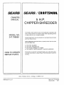
OWNERS
MANUAL
MODEL NO.
247.796890
_
WARNING
Carefully
read and
follow
Safety
Rules, Precautions
and Operating
Instructions,
Failure
to do so can result
in serious personal
injury.
5 H.P.
CHIPPER-SHREDDER
It
tl
Assembly
• Maintenance
Operation
, Repair Parts
Always wear eye protection during
operation
i i ,,,,,,,,,
Sold by Sears,
Roebuck
and Co, Chicago
ilt
60684
USA
Part No. 770-5875B
8/87
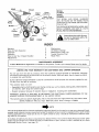
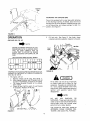
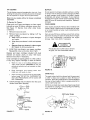
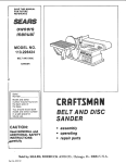
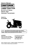
REAR
lopper
MODEL
NUMBER
SERIAL
NUMBER
Chute
Deflector
Chip-It
Spark Plug.
and Elbow
THE
MODEL
AND
SERIAL
NUMBERS
WILL BE FOUND ON THE MODEL PLATE
ATTACHED TO THE FRAME SEE ILLUSTRATION AT LEFT
Eel
Ramp
Muffler
YOU SHOULD RECORD BOTH MODEL AND
SERIAL NUMBERS AND KEEP IN A SAFE
PLACE FOR FUTURE REFERENCE,
Cleaner
Catcher
Bag
Starter
Control
Tank
Model
Plate
i&
FRONT
l
Instructions given with this symbol are for personal safety° Be
sure to follow them.
INDEX
2
3
Warranty
......
Rules for Safe Operation
Assembly
Operation
How to Use Your Chipper-Shredder
Adjustments
_
Maintenance
Off-Season
Maintenance
4
6
7
9
For one year from the date of purchase,
and tuned up according to the instructions
in material and workmanship.
warranty
does
necessary
or rental
purpose,
this warranty
applies
for only
blade guides,
blade adapters,
not cover:
because
of operator
abuse
normal
use, such
or negligence,
WARRANTY
SERVICE IS AVAILABLE
BY RETURNING
THE
NEAREST SERVICE CENTER/DEPARTMENT
IN THE UNITED
This warranty
GAS CHIPPER-SHREDDER
when this Craftsman
Chipper-Shredder
is maintained,
lubricated
in the owner's manual, Sears will repair, free of charge, any defect
-- Expendable
items which become worn during
air cleaners, spark plugs and catcher bags;
-- Repairs
Contact your nearest Sears store for details°
ON CRAFTSMAN
tf this Craftsman
Chipper-Shredder
is used for commercia_
30 days from the date of purchase
This
12
13-19
AGREEMENT
A Sears Maintenance Agreement is available on this product
ONE YEAR WARRANTY
9
11
12
........
List ....
Trouble Shooting
Chart
Repair Parts
......
MAINTENANCE
LIMITED
.......
Storage
Check
as blades,
including
CRAFTSMAN
STATES
bent
crankshafts
CHIPPER-SHREDDER
gives you specific legal rights, and you may also have other rights which
SEARS, ROEBUCK AND CO, Dept 698t731A,
Sears Tower, Chicago,
TO THE
vary from state to state
IL 60684
NOTE
This unit is equipped with an internat combustion
engine and should no[ be used on or near any unimproved
forestcovered, brush-covered
or grass-covered
land unless the engine's exhaust system is equipped with a spark attester
meeting applicable tocaf or state laws (if any) If a spark attester is used, it should be maintained
in effective working order by the operator
In the State of California the above is required by law (Section 4442 of lhe California Public Resources Code) Other
states may have similar laws Federal law apply on federaf lands A spa_k arrester muffler is available at your Sears
Authorized
Service Center
(see page 19)
WARNING
-
-
_
Toreducethe
tions
Failure
RULES
potential for any injury, comply
to comply with the instructions
FOR SAFE OPERATION
TRAINING
1
2.
3.,
4,
5.
6,,
7,
rocks, bottles, cans or other foreign objects are not
included
2
If the cutting mechanism
strikes any foreign object
or if your machine should start making an unusual
noise or vibration, immediately
stop the engine and
disconnect the spark piug wire from the spark plug
Allow the machine to stop and take the following
steps:
A
Inspect for damage
B Replace or repair any damaged parts
C
Check for any loose parts and tighten to assure
continued
safe operation
3
The engine must be kept clean of debris and other
accumulations_
4
Do not allow an accumufation
of processed material
to build up in the discharge
area as this will prevent proper discharge and can result in kick-back
from feed opening
5
Never allow your hands or any other part of your
body or clothing
inside the feeding
chamber,
discharge chute or near any moving part while the
engine is running
6
Keep ell guards and deflectors
in place and in
good working condition
to assure continued
safe
operation
7
Always stand clear of the discharge
area when
operating
this machine
8
Keep your face and body back from the feed
opening to avoid accidental
bounce back of any
materiel
9
Do not over.reach
Keep proper balance
and
footing at all times
10 The engine governor
settings
on your machine
must not be altered, changed,
or tampered
with,
The governor controls the maximum safe operating
speeds and protects
the engine and all moving
parts from damage caused by overspeed,
11 Do not transport machine while engine is running
12 Do not operate
engine if air cleaner or cover
directly
over carburetor
air intake is removed,
except for adjustment
Removal
of such parts
could create a fire hazard.
Read this owner's manual carefully in its entirety
before attempting
to assemble
or operate
this
machine
Be completely
familiar with the controls
and the proper use of this machine before operating
it, Keep this manual in a safe place for future and
regular reference
and for ordering
replacement
parts,
Children
must never be allowed to operate this
equipment_
No one should operate this unit while intoxicated or
while taking medication
that impairs the senses or
reactions
This equipment
should never be operated
in the
vicinity
of children, pets or other persons
Never run your machine in an enclosed area as the
exhaust from the engine contains carbon monoxide, which
is an odorless,
tasteless
and deadly
poisonous
gas
Never allow your hands or any part of your body or
clothing
inside the feeding chamber,
discharge
chute, or near any moving part while the machine
or engine is running
If it is necessary for any reason to inspect or repair
the feeding chamber or any part of the machine
where a moving part can come in contact with your
body or clothing, stop the machine, allow it to cool,
and disconnect
the spark plug wire from the spark
plug before attempting
such inspection
or repair
PREPARAT'ION
t,
2.
3
4_
5,
Wear safety
glasses
provided
with
your unit
while operating the chipper-shredder
to prevent injury from any chips which may be ejected out of
the openings
Wear proper apparel
Avoid wearing loose fitting
clothing,
Wear gloves when handling material
HANDLE
FUEL WITH CARE as gasoline
is an
extremely
flammable
fuel
A
Check the fuel before starting the engine, Do
not fill the fuel tank indoors, while the engine
is running, or while the engine is still hot,, Turn
the unit off and let the engine coot before
refueling,
B, Fuel your chipper-shredder
in a clean area Do
not smoke while refueling,
C
Fuel tank cap must be secure at all times
except during refueling
D
Avoid spilling gasoline or oil. Wipe the unit
clean of any spilled fuel or oil,
E Store fuel and ell in approved containers, away
from heat or open flame, and out of reach of
children,
This machine should be operated only upon an
level earthen surface
Assure that aft screws, nuts and bolts and other
fasteners
are properly secured
MAINTENANCE
1
2
3
OPERATION
1,
When
ment,
with the following
safety instrucmay result in personal injury
feeding shreddable materiat into this equip*
be extemely
careful that pieces of metal,
3
AND
STORAGE
When this equipment
is stopped
for servicing,
inspection,
storage or to change an accessory,
make sure the spark plug wire is disconnected
from
the spark plug The machine should be allowed to
cool down before making
such inspection,
ad_
justments, service, etc Maintain your machine with
care and keep it clean for the best and continued
safe operation,
Do not use flammable
solutions
to clean the air
fitte_
When not in use, your machine should be stored out
of the reach of children Keep where gasoline fumes
will not reach an open flame or spark, For long
periods of storage, the gasoline should be drained
and disposed in a safe manner, Always allow the
machine to cool before storing in any enclosure
ASSEMBLY
NOTE
Tools
This unit is shipped WITHOUT GASOLINE
or OIL, After
assembly,
see operation
section of this manual for proper fuel and
engine oll recommendations
Required
121
(1)
INSTRUCTIONS
for Assembly:
7/16" Open
1/2" Socket
End or Box Wrenches"
Wrench
* An Adiustable Wrench
of the wrenches
may be used in place of one
UNPACKING
NOTE
The right and left side of your chippershredder is determined
from behind the
unit,
Remove the chipper-shredder
and loose parts from the
carton,, Make certain all parts and literature have been
removed before the carton is discarded,
Parts
in Carton:
Chipper-Shredder
Chute Deflector
Hopper
Upper Leaf Ramp Section
Catcher Bag
Hardware
Pack
Safety Glasses
Contents
A
B
C
(8)
(8)
t6)
D
(2)
of Hardware
Hex Bolts 1/4-20 x 1/2" Long
Hex Lock Nuts 1/4-20 Thread
Hex Washer Head Self-Tapping
5/16-18 x 3/4" Long
Keepers
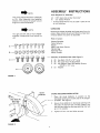
o--@@
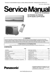
FIGURE
1):
Screws
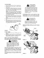
1,
Chute
Deflector
CHUTE
1,
..,_.Nuts
Place
the
chute
INSTALLATION
deflector
in position
on
the
opening (on the left side of the chipperSee figure 2
2
Secure chute deflector to discharge opening with
hex bolts (A) and hex lock nuts IB) Heads of the
hex bolts are inside the discharge opening Hex nuts
go on the outside
3
Tighten
j-
2.
DEFLECTOR
discharge
shredder)
Hex Bolts (A)
Hex Lock
FIGURE
Pack (See Figure
all four
nuts and bolts
securely
No
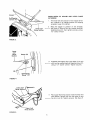
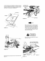
INSTALLATION
EXTENSION
Self-Tapping
Screws (C)
1.
Lower Leaf
Ramp Section
FIGURE
--
OF HOPPER AND UPPER GUItDE
The lower leaf ramp section on the chipper-shredder is placed in an upright position
for shipping
purposes
Lower this section,
2,
m
Place the hopper
in position
on the shredder
See figure 3. Start all four hex washer head selftapping screws/C),'then
tighten securely using a
1/2" socket wrench
3
Assembte the keepers (D) to the sides of the unit
with two hex washer head self-tapping screws (C),
using a t/2" socket wrench, T_ghten securely
4
Place upper leaf ramp section inside the lower fear
ramp section
Secure with four hex bolts (A) and
hex lock nuts (B). Tighten securely
See figure 5
3.
Lowe r
Leaf
Ramp
Section
Keeper(D)
•--------
\ _
Self-Tapping
Screw (C)
FIGURE 4.
Lower Leaf __
Ramp Section _
\
Ramp Section
FIGURE
5.
ATTACHING
THE CATCHER
BAG
Your unit is equipped with a nylon bag which attaches
to the discharge opening. If desired, place the end of
the bag over the chute deflector. Depress plunger, pull
on the drawstring,
and reIease plunger to lock it in
position.
See figure 6
FIGURE 6.
.......................
oPERATION
:. .............................
2
Fill fuel
unleaded
ii lUHl=
tank. See
automotive
figure 8. Use fresh, clean,
gasoline. Capacity is 3 quarts_
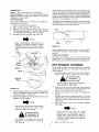
GAS AND OIL FILL tJP
NOTE
Throttle
Control
ENGINE lS SHIPPED WITHOUT OIL. FILL
CRANKCASE WITH OIL BEFORE STARTtNG BE VERY CAREFUL NOT TO
ALLOW DIRT TO ENTER THE ENGINE
WHEN CHECKING OR ADDING OIL OR
FUEL
Recommended
SAE Viscosity
Lever
luffler
Fuel
Tank
• park
Plug,
and
Grades
LIII TI !o! o T9
ErrI, ,,,!
! r !t!r
-20 °
0o
32 °
60 °
80 °
100 °
FIGURE 8,
TEMPERATURE RANGE EXPECTED BEFORE NEXT OIL
CHANGE, ALL OILS MUST A,PI SERVICE CLASSIFICATION SD, SE OR SE
1,
t w...,.ot
Fill engine with oil,
a
Remove
engine oil fillplug. See figure 7.
b. With chipper-shredder
level, fill engine with oil
to point of overflowing.
Capacity is 1-1/4 pints
c
Tilt chipper-shredder
forward
on its wheels,
then re-level.
d
Check oil level, Refill to point of over-flowing
if necessary.
Replace oil fill plug.
j o_
Fill to within
1/2 inch of top of fuel tank
to prevent spills and to allow for fuel
expansion
If gasoline is accidently
spilled, move chipper-shredder
away from
area of spill Avoid creating any source of
ignition
until
gasoline
vapors
have
disappeared,
\'tll)
)i
Plug
NOTE
DO
NOT
USE
GASOHOL
OR
METHANOL.
These type fuels react with
water content in the fuel and tend to form
strong acids which can corrode metal
parts and harm rubber plastics_
t
USE CLEAN OIL AND FUEL. STORE IN
APPROVED,
CLEANI
COVERED
CON+
TAINERS, USE CLEAN FILL FUNNELS.
Oil Drain Plug
FIGURE
7.
6
TO START ENGINE
1,
Attach
2.
Place the throttle
See figure 8
spark
ptug wire
3.
Grasp starter handfe (see figure 9) and pull rope
out slowly until engine reaches start of compression cycle (rope will pull slightly
harder at this
point). Let the rope rewind slowly
control
and boot
to spark
NOTE: A noise will be heard when finding
the
start of the compression
cycle This notice is
caused by the flails and fingers which are part
of the shredding
mechanism
falling into ptace,
and should be expected,
4
5,
6,
i wARN,I G
plug
lever in START position
Pull rope with a rapid, continuous,
full arm
Keep a firm grip on start handle Let rope
slowly. Do not let starter handle snap back
starter,
Repeat preceding instructions
3 and 4 until
fires,
stroke
rewind
against
_
Air
i .Screen
-
if if becomes
necessary
to push materials
into the
chipper-shredder,
use a small diameter
stick, NOT
YOUR HANDS The stick sl_ould be small enough that
it will be ground up if it gets into the impeller assembly.
engine
After engine starts, move throttle control lever on
engine to slow position for a few minutes warm up,
Then move throttle control lever to RUN position
for shredding-chipping
operations
""-" .........
The chipper-shredder
discharges material
with considerable
velocity
Keep away
from the area around the discharge chute
Always stop the engine and d_sconnect
the spark plug wire when removing
or
attaching
the bag
when
changing
containers
or when
removing
the
shredded material
Do not deposit material larger then 12"
diameter in the hoppe_ or upper guide
extension Any material heavier then 1/2"
should be fed _nto the chip-it guide
Leaves and smaller branches
can be fed into the
hopper with the leaf ramp raised as shown in figures
10 and 11
Hopper
Chip-it
Guide
FIGURE 9.
TO STOP ENGINE
1
2,
Move throttle control lever to STOP position
See
figure 8
Disconnect
spark plug wire from spark p_ug and
ground against the engine to prevent accidental
starting while equipment
is unattended
HOW TO USE YOUR CHIPPER-SHREDDER
Your shredder is designed for safe, efficient operation.
KEEP HANDS AND FEET AWAY FROM ALL OPENINGS
FIGURE
10.
WARNING
No larger than
112 inch diameter
Wear the safety glasses provided
with
your unit while operating
the chippershredder to prevent injury from any chips
which
may be ejected
out of the
openings,
Make certain chip-it guide is
closed when not in use,
Wear gloves when handling
material
Feed material
into the chipper-shredder
at a steady
rate
It is
possible to feed too fast° Experiment with feeding rates
to determine
what
rate provides
the best results
without
stalling the engine or plugging the discharge
chute.
The discharge chute will direct the shredded material
into a pile, a container
or the bag provided with your
shredder
)or
Chip-it
Leaf
Ramp
FIGURE
11
Lower the
up on the
twigs can
leaf ramp
leaf ramp by holding the handle and pulling
release bar See figure 12 Leaves and small
be raked into the chipper-shredder
with the
in this position
See figure 13
No larger than
1t2 inch diameter
Elastic
> Lock
Nuts
Leaf
Ramp
Handle
FIGURE
14.
\
FIGURE
Bulky material, such as stalks or heavy
branches (anything
over tt2" diameter),
should be fed into the chip-it guide.. See
figure 15. Do not force or jam material into the chip-it
guide Make certain leaf
ramp is raised as shown in figure 15 when
using the chip-it guide
12.
Make certain chip-it
when not in use
guide door is closed
Keep Leaf Ramp Raised
When Using Chip-It Guide
Leaf Ramp
FIGURE
,_(
13o
Small branches
figure 14
can also be fed into the leaf ramp
See
FIGURE
15,
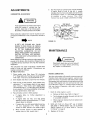
ADJUSTMENTS
CARBURETOR
Test the engine by operating the chipper-shredder.
If engine tends to stall or die out, it dsually
indicates that the mixture is slightly lean and it may
be necessary to open ,f',)
the needle valve slightly
to
provide
a richer
mixture
This
richer
mixture may cause a slight unevenness
in idling.
ADJUSTMENT
Idle Speed
Adjusting
Screw
If any adjustments
are made to the engine
while the engine if running
{eg. carburetor), keep clear of all moving parts
Be careful of heated surfaces and muffler
Minor carburetor
adjustment
may be required to compensate for differences
in fuel, temperature, altitude or
toad
i
Throttle
L
Needle
NOTE
FIGURE
A DIRTY AIR CLEANER WILL CAUSE
ENGINE TO RUN ROUGH
BE CERTAIN
AIR CLEANER IS CLEAN AND ATTACHED TO THE CARBURETOR
BEFORE
ADJUSTING
CARBURETOR
DO NOT
MAKE UNNECESSARY
ADJUSTMENTS
FACTORY SETTINGS
ARE SATISFACTORY FOR MOST APPLICATIONS
AND
CONDITIONS.
Never attempt to change maximum engine speed It is
pre-set at the factory and should be changed only by
a qualified service technician
who has the necessary
equipment,
Close needle valve
(See figure
16) clockwise
(("_ } finger tight only Forcing may cause damage_
Then open 1-!/2 turns counterclockwise
(r'x)
2.
Start
engine
3
With throttle in RUN position, close needle valve
clockwise
(;-_,) until engine starts to lose speed
(lean mixture).
Then slowly
open needle valve
counterclockwise
(f'_) until engine JUST BEGINS
to run unevenly This mixture should be rich enough
for best performance
under load.
Place throttle
a_
b
If engine
necessary.
and allow
control
idtes,
to warm
for five minutes.
no
further
adjustment
tf engine idles too fast, turn
adiusting screw counterclockwise
slower speed is obtained
ENGINE LUBRICATION
Your four cycie engine will normally consume some oil;
therefore check engine oil level regularly - approximately,
every five hours of operation
and before each usage
Stop engine and wait several minutes before checking
oil level. With engine level, the oil must be even with
the oil fill (refer to figure 7) Change engine oil after the
first two hours of operation, and every twenty, five
hours thereafter
is
idle speed
_(-",) until
c
If engine dies, turn idle speed adjusting screw
1f4 turn
clockwise
((-'_)
Place throttle
control in FAST position
and restart engine
d
Move throttle
control
to IDLE position
engine does not idle, repeat step c
16.
Disconnect
spark plug wire and ground
it against the engine before performing
any repairs or maintenance.
I_
in IDLE position:
Valve
MAINTENANCE
The carburetor
may need re-adjusting
if engine lacks
power or does not idle properly
if adjustments
are
needed, proceed as follows.
To Adjust Carburetor:
1.
Throttle
Stop
Drain oil while
engine
oil drain
is warm
a.
Remove
plug
Refer to figure
7
b.
Tip the chipper-shredder
in a suitable container
forward,
c.
When engine is drained
plug securely.
of all oil, replace drain
and catch oil
2
Refif] with fresh oi! Above 32 ° , use oil labeled
SAE 3OW or !0W30
Below 32 °, use oil labeled
5W20
Capacity is 1-1i4 pints Refer to "Gas and
Oil FilFUp" on page 6
3.
Replace
If
oil fill plug
AIR CLEANER
MUFFLER
The air cleaner prevents damaging dirt, dust, etc, from
entering the carburetor and being forced into the engine
and is important
to engine life and performance
Do not operate the chipper-shredder
without a muffler
or tamper with the exhaust system Damaged mufflers
or spark attesters
could create a fire hazard inspect
periodicalty, and replace if necessary, If your engine is
equipped with a spark arrester screen assembly, remove
every 50 hours for cleaning and inspection
Replace if
damaged
Never run your engine without
assembled-
air cleaner completely
To Service Air Cleaner:
CLEAN
Clean and re-oil foam pro-cleaner at three month
intervals or every 25 hours, whichever occurs first:
See figure I7 Service more often under dusty
conditions
ENGINE
1,
Remove knob and coven
Clean engine perlodicailyl
Remove dirt and debris with
a cloth or brush Cleaning with a forceful spray of water
is not recommended
as water could contaminate
the
fuel system,
2,
Remove foam pre-cleaner by sliding it off the
paper cartridge.
ao Wash foam pre-cleaner in liquid detergent
and water_
Yearly or every 50 hours, whichever occurs first, remove
the blower housing and clean the areas shown in figure
18 to avoid overspeeding,
overheating
and engine
damage
Clean more often if necessary,
3.
b
Wrap foam pre-cleaner in cloth and squeeze
dry.
c
Saturate foam pre-cleaner in clean engine
oil, Sqeeze to remove excess oil
Periodically
clean muffler area to remove
all grass, dirt and combustible
debris,
Install faom pre-cleaner over paper cartridge°
Reassemble cover and screw down tight,
Replace and clean cartridge included with dual
element air cleaner yearly or every 100 hours,
Service more often if necessary.
Clean Out
Chaff and
Dirt
Clean cartridge by tapping gently on a flat surface
If very dirty, replace cartridge or clean as fotlows:
4_
a
Wash in a tow or non-sudsing detergent and
warm water solution CAUTION: Do not use
petroleum solvents such as kerosene, to clean
cartridge
b.
Rinse thoroughly with flowing
inside out until water is clear.
c
AHow cartridge to stand and air dry thoroughly
before using
DO NOT OIL CARTRIDGE, DO
NOT USE PRESSURIZED
AIR TO CLEAN OR
DRY CARTRIDGE
Install
Screw
cartridge
and pre-cleaner
knob down securely,
water from
then
18
SPARK
PLUG
The spark plug should be cleaned and the gap reset
to 030" at least once a season or every 50 hours of
operation
Spark plug replacement
is recommended
at
the start of each season, Refer to engine parts list for
correct spark plug type
the cover,
NOTE: Do not blast clean spark plug Spark plug should
be cleaned by scraping or wire brushing and washing
with a commercial
solvent
(_Tj-._----_ Knob
"
FIGURE
._' Cover
,030 Feeler Guage
j
.i,(_
"¢<1&_£._¢___,._-Cart ridge
Spark
FIGURE
!7_
FIGURE
10
!9,
Plug
LUBRICATION
Wheels - The wheels require no lubrication,
Flails and Fingers - If the unit is disassembled
for any
reason, lubricate the flails and fingers with a light oil
(engine oil may be usedt
CUTTING
BLADE
When sharpening
the blade, follow the original angle
of grind as a guide. It is extremely
important that each
cutting edge receives an equal amount of grinding to
prevent an unbalanced blade An unbalanced blade wil!
cause excessive vibration when rotating at high speeds
and may cause damage to the unit
The cutting
blade may be removed
replacement
as follows
1
Lower the upper guide extension
The blade can be tested by balancing it on a round shaft
screwdriver
or nail Remove metal from the heavy side
until it balanced evenly See figure 21
for grinding
or
2,
3.
Block up the housing
See figure 20.
Remove the four elastic lock nuts from the back
of the housing using a 1/2" wrench
Refer to figure
14. Separate the shredder into two halves
4,
Remove
the
back-up
ptater See figure
Nai,
/
\
20
NOTE
°,o0e C7
When reassembling,
make certain the
opening on the back up plate is toward
the bottom of the unit The back up plate
may be reversed to provide a new cutting
edge
,
,
WeEd B
FIGURE 21
When reassembling
the blade, tighten to between 375
and 450 inch pounds, or lacking torque wrench, tighten
securet¥
FLAILS AND FINGERS
,
The flails and fingers may be _eversed when they
become dull It is suggested
that this procedure
be
performed
by your nearest Sears Service Department
x.,
Blade
OFF-SEASON
tf the chipper-shredder
longer than 30 days,
recommended.
Blade
I
STORAGE
is to be inoperative for a period
the following
precautions
are
Working outdoors, drain all [uel from the fue! tank.
Run the engine until it stops from lack of fuel
/
Back-Up
Plate_.
/
,__
.....
DO NOT DRAIN FUEL WHILE SMOKING,
OR IF NEAR AN OPEN FIRE
FIGURE
5.
6,
2,
Drain alI the oil from the crankcase (this should be
done after the engine has been operated and is still
warm) and refill crankcase
with fresh oi!
3
Protect
follows
20,
Hold the blade retainer on the impeller assembly
with an adjustable wrench to keep the blade from
turning as shown in figure 20
Remove the blade by removing the center bolt, lock
washer and fiat washer
NOTE
4
the
inside
of the
engine
for
storage
Remove spark plug, pour approximately
!/2 ounce
(approximately
one tablespoonl
of engine oil into
cylinder and crank slowly to distribute
oil Replace
spark plug
Clean the engine and the entire chipper-shredder
thoroughly
Use caution when removing the blade to
avoid
contacting
the
weld
bolts
protruding
from the housing.
NOTE
When
storing
any
type
of power
equipment
in an unventilated
or metal
storage shed. care should be taken to
rustproof the equipment.
Using a tight oil
or silicone, coat the equipment,
especially
all moving parts
WARNING
The blade is reversible
and can be
assembled to the crankshaft
with either
side showing
Store in a clean,
1!
as
d_y area
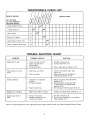
MAINTENANCE
SERVICE
CHECK
LIST
RECORD
SERVICE
DATES
FILL tN DATES
AS YOU COMPLETE
REGULAR SERVICE
Check
Change
Clean
Service
,
Engine
Oil Level
Engine
9 V"
Oil
Engine
Air Cleaner
, .....
,,,
Clean
Engine
Cylinder
Clean
or Repface
Spark
Fins
Plug
TROUBLE
SYMPTON
POSSIBLE
Engine fails to start
Spark
plug wire
2,
Dirty
air cleaner
1. Connect
and tighten spark plug
wire (p 6)
2 Clean air cleaner as described
in
maintenance
section (p !0),
1
2
Carburetor
not adjusted
properly
Air flow restricted.
3
Engine
Material
Engine
stalls
or loss of
overheats
not shredding
bogs
down
NOTE: For repairs
or
beyond
1
SOLUTION
CAUSE(S)
] Fill tank
2 Connect
3
Engine
CHART
Check fuel tank for gas,
Spark plug lead wire
disconnected
Faulty spark ptug
2
Hard starting
power
SHOOTING
the minor
loose,
flails
not sharp
No fuel in fuel tank
Feeding material into
machine too quickly,
adjustments
listed
adjust
gap or replace
(p, 10)
Adjust carburetor,
See adjustment
section (p, 91
2. Remove blower housing and clean
as described
in the maintenance
section
(p_ 10)
with the proper oil (p. 6),
3, Fill crankcase
oil level tow
Blade andlor
t
2.
3 Ciean,
if empty ip. 6)
lead wire (p, 6)
12
or reverse
blade and flails
(13.11)
1, Fill tank if empty (13.6),
2. Do not force material into the opening
Feed gradually
(p. 7)
the
above,
Sharpen
please
contact
your Sears
Authorized
Service
Center
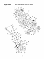
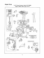
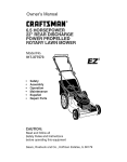
Repair Parts
5 H.P. Chipper-Shredder--Model
1
2
3
4
247.796890
5
9
42
13
14
/7 5?
18
/
38
34
24
\
25
43
\
53
52
13
20
Repair Parts
5,H°P.
Chipper-Shredder--Model
.'evI
Key
Non
Part Noo
Description
1
2
3
4
5
6
7
8
9
11476
710-0465
711-0580
711-0579
11455
736-0921
726-0111
712-0922
714-0507
10
11
12
13
14
15
t6
t7
18
19
20
2t
22
23
24
25
26
27
28
29
30
16568
712-0107
710-0289
714-Ol14
13430
710-0157
736-0119
14573
5 HR
11464
712-0123
736-0119
738-0521
736-0170
726-0221
711-0494
734-1173
736-0100
710-0624
712-0429
710-0237
Door Chip It
Hex Bolt I12o20 x 4 50" Lg,*
Clevis Pin
Flail Spacer W32" Lg
Cutting Finger
L-Wash
1/2" I,D.*
Patnut 3/16" Dia,
Hex Jam Nut 1!2-20 Thd*
Cotter Pin 3/32"
Dia x 3/4"
Lg*
Chute Deflector
L.-Nut t/4-20 Thd
Hex Bolt 114-20 x 50"
Lg.*
Sq Key ti4" x 2(
Lg,
Impeller Assembly
Hex Bolt 5116-24
3/4" Lg,"
L-Wash_ 5t16"' ID,'
Hopper to Engine Mtg, Plate
Engine - B & S 13
:12-1731-01
Engine Mounting
ate
Hex Nut 5/16-24
"hd*
L,-Wash
5t16" I.D
Shaft
Special L-Wash
5'16" ID
Push Cap
Spacer
Wheel Ass'y-Com!
Fl,-Wash
50" t,D,
Hex Bolt 5/16-24
1 50" Lg,*
Elastic Lock Nut 5t16-18 Thd
Hex Bolt 5116-24
62" Lg,*
*Common
NOTE:
247_796890
Hardware
Specifications
- May be purchased
subject
to change
Part No.
No_ I
31
I 7t4-0144
32 1 736-0192
33 I
34
35
36
11459
I 711-0564
1 711-0578
I 736-0247
37
38
39
4O
I
1
I
I
736-O2t7
710-O'151
14575--629
732-0546
41
42
43
44
45
46
47
48
49
50
I
t
I
I
I
t
1
l
I
I
11477
11478
747-O53t
712-0109
]3431
11460--629
16524--629
736-0264
11481--629
710-0601
52
53
55
56
57
{
1
f
[
I
11454
16522
11480
710-0542
735-0639
764-0199
723-0400
notice
Cotter Pin 1/8" Dia x 100"
Lg" (Specia0
Ft-Wash
,531" ID x 937
OD x .09
Ftai]
Flail Spacer 23132" Lg
Clevis Pin 50"
Dia, x 30"
Lg
F1,-Wash, 406" ID, x 125"
O-D, Hdn,
L,-Wash 3/8" ID HD,
Hex Bolt 318-24 x 20"
Lg HT
Flail Housing Ass'y.-Comp
Torsion Spring
062 Dia x 106
Lg.
locally.
without
Description
or obligation,
!4
Chip-It Guide Ass°v.
Hinge Pin
Release Bar
Wing Nut Elastic 1/4-20 Thd
Blade
Upper Leaf Ramp Section
Lower Leaf Ramp Section
FL-Washo 5t16" LD
Hopper Assembly
Hex Wash,. Hd, Self-Tap Scr
5/16-18 x 75" Lg
Back-Up Plate
Inlet Guide Assembly
Stop Washer
Hex Bolt 5/16-t8 x 8,38" Lg
Spark Plug Elbow
Bag (Not Shown)
Safety Glasses (Not Shown)
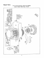
Repair Parts
5 H.P, ChipperShredder--Model
Engine--Model
130212
247.796890
Type 1731-01
26
541
(
208
)
201
383
P
30
35
36
741
529
16
615
@6'
_IIC
SPE¢IALIOOLS REQUIRED
TO INSTALL
230
46
SEE REPAIRINSTRUCTION
MANUAL
15
219
@
[358 GASKET
220
SET I
298
_'25
0
299
!5
Repair Parts
5' H.R Chipper-Shredder--Mode!
Engine--Model
130212
247.796890
Type
1731-01
*BEouInEs
SPECIAL
TOOLS
Zo_ LNS_T
.ALL
363
SEE REPAIR
INSTRUCTION
MANUAL.
24
3O4
74
73
f
200
305
57
655
346
37
16
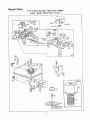
Repair Parts
5 H,P. Chipper-ShredderiModel
Engine--Model
634_e_e,,_
152
130212
609
247,796890
Type 1731-01
u_
_
_(_ 542
03 205
\
612
]4u
__
J '
lfi_b1394
433
190
2O6
191
124
409
473
621
223
526
642
209
_166
445
446
163
17
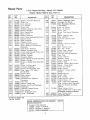
Repair Parts
5' H.P_ Chipper-Shredder-Engine-Model
KEY
NO
PAR3"
NO.
1
2
395990
297565
Note:
3
5
7
8
9
10
tl
12
299819
211542
* 270383
294178
"27549
Model
130212
DESCRIPTION
'KNE'_
Cylinder Assembly
Bushing-- Cylinder
Requires special tools for
installation
Seal-- Oil
Head-Cylinder
Gasket-Cylinder
Head
Breather-Valve
Chamber
Gasket-Valve
Cover
Screw--Breather
Mtg Sam
Grommet-Breather
Tube
Gasket--Crankcase-015
thick
Standard)
"270125
Gasket-Crankcase005" thick
"270126
Gasket-Crankcase009"' thick
13
93368
Screw-Cylinder
Head
(2-3/32"
long)
14
93369
Screw--Cylinder
Head
(2-15/32"
long)
T5
91249
Plug-Pipe,
1/4" Std
Square Head
To Replace Crankshaft
Gear Pin,
Order Part No,, 230978
16
398098
Crankshaft
18
298517
Cover Assy.,-- €.;rankcasc
19
297603
Bushing--Crankcase
Cover
Note:Requires
special tools for
}nsta!lation
20
298504
Oil Seal and Spacer
21
66768
Plug--Oil
Filler
22
93032
ScrewCrankcase Cover
Mounting
Sere
23
297229
Flywheel-Magneto
24
222698
Key--Flywheel
25
298904
Piston Assy-Standard
298905
Piston Assy,-,010"
O,S
298906
Piston Ass_z,- O20" OS
298907
Piston Ass,/,- 030" O D
PISTON RING SETS:
Note:For Chrome Piston
Ring Set - Standard Size -=
Order Part No. 299742,
26
298982
Ring Set-Standard
Piston
298983
Ring Set-010"
OS Piston
298984
Ring Set-,020"
O.S Piston
298985
Ring Set-030"
OS. Piston
27
26026
Lock-- Piston Pin
28
298909
Pin Assy-PistonStandard
298908
Pin Assy.-Piston-005"
0S,
29
299430
Rod AssyConnecting
Note: For Connecting
Rod with
,020" undersize Crankpin Bore-Order No. 390459,
30
221980
Dipper--Connecting
Rod
Type
32
247,796890
1731-01
PART
NO
92296
211119
261044
26478
40
45
46
52
93394
66578
"27OO80
93312
260642
212733
"27355
299431
295871
66884
230228
1
93105
.394897
63770
298436
394506
221923
93490
68
70
71
73
74
75
9O
95
220865
397940
93499
211203
299212
108
397134
1114| 66594
/!16 1 65978
[ 17 ! 230590
!118/ 23433
93357
1124 |
I 1 22831
f147/ 230591
22235
1148I
h49 1
26336
260575
93527
96
97
t
154 1
163
t66
|
|
t8o /
Ig;l
18
271139
231332
397137
394818
93440
DESCRIPTION
Lock- Screw Head
Screw-- Connecting
Rod
Valve-Exhaust
Valve- Intake
SpringIntake VaNe
SpringExhaust Valve
Guard - Flywheel
Retainer-Valve
Spring
Tappet --Valve
Gear-Cam
Gasket-Carburetor
Mounting
(2)
HousingRewind Starter
Pulley- Rewind Starter
(Includes 63" long rope)
SpringRewind Starter
Rope--Rewind
Starter-63" Ionc
Pin-Starter
Grip
Grip-Starter
Rope
Screw-Standard
Steel Housing
Mtg. Sem
Clutch Assy-Rewind
Starter
HousingStarter Clutch
Bali - Clutch
RatchetRewind Starter
Washer-Clutch
Retainer
ScreenStarter Pulley
ScrewSem
WasherSpring
Carb Assy
Screw--Throttle
Valve to Shaft
Sere
ThrottleCarburetor
Shaft and LeverThrottle
Valve GroupChoke
Gasket-Needle
Valve Nut
Packing-- Needle Valve
Nut- Needle Valve
Valve -- Needle
Screw-Hex
Head
Plug --Welch
Seat- Needle Valve
Washer--Needle
Valve (2)
Spring-Needle
Valve
Spring--Throttle
Adjustment
Screw-Machine,
Rd., Hd_-5-40 x 5f8"
Gasket-Air
Cleaner Mounting
Stud-Air
Cleaner
Tank AssembJy-FueJ
Cap-Fuel
Tank
Screw-- Fuel Tank Mounting
Sem (2)
Note: 94094 Screw-Fuel
Tank
Mounting
fl)
Repair Parts
5 H°P. Chipper-Shredder--Model
Engine--Model
KEY
NO.
PART
NO.
"271592
221480
261558
260678
393919
222962
93838
280012
230946
260695
209
216 l 397709
217
261951
2191 391737
220
221551
223
221517
224
93491
191
200
201
202
203
204
205
206
208
227_
230i
256
298
299
304
305
306
307
393920
22245O
397709
261409
393368
299410
93158
221511
93042
308
333
335
337
221512
397358
93414
346
356
358
363
93705
398808
397145
19069
373
383
392
394
409
432
433
434
93987
89838
260455
270026
299837
221377
93265
210959
298809
247.796890
130212
DESCRIPTION
GasketFuel Tank Mounting
Guide-Air
Link- Governor
Link -Throttle
......
CrankBelt
Bushing--Governor
Lever [Flat)
ScrewShoulder
Nut-Control
Rod
Rod- Control
SpringGovernor
Link-Choke
(Includes Bell Crank)
Spring-Choke
Gear- Governor
Washer-Thrust
Lever-Governor
Control
Rivet-Governor
Control Lever
Mounting
Lever Assy - Governor
WasherGovernor Lever
Crank--Bell
(Includes Choke Link)
Locknut-- Muffler
MufflerExhaust
HousingBlower
Screw-Blower
Housing Mounting
Shield - Cylinder
Screw-Cylinder
Shield Mounting
Sem
Type
1731-01
KEY
NO,
PART
NO
435
445
93141
396424
271466
446
467
473
526
222844
212706
93612
933a3
527
528
529
541
542
552
221514
231386
67838
22398
94025
231079
562
592
608
609
6tt
612
614
615
616
621
634
634A
642
655
676
92613
231082
390463
260294
391813
296811
93306
93307
231077
297472
271853
270382
223306
222598
395700
681
725
741
851
852
869
870
299060
223334
261696
221798
396397
211787
211172
871
231348
987
988
398970
735-0639
CoverCylinder Head
Armature
Assembly
Screw--Armature
Mtg Sere
Plug-Spark
1-112" High37-42 MM
ScrewSere
Wire- Ground
Gasket Set
Flywheel
Puller (Optional
Accessory
Nut-Hex
WrenchSpark Plug
Spring-Fuel
Pump Diaphragm
Diaphragm
Lever-Trol- Speed Control
Cap- Spring
Pin-Diaphragm
Cover
Cover-Diaphragm
DESCRIPTION
Screw-Diaphragm
Cover
Cartridge--Air
Cleaner
Foam Pre-Cleaner Element
(not shown)
e,Jse -Air Cleaner
Knob
Air Cleaner
Screw
Sere
S_.,ew Tank Brackel Mounting
Sere
Clamp
Breathe_ Tube
Tube
Breather
Grommet
Bt'eathu, r Tube
Washer
Screw
Bushing
G(_vmnor Crank
(l,'4-I D)
Bolt
Governor Lever
Nut
Hex
10 24
Starter Assy
Rewind
Spring
[hrotlle Link
Fuel Pipe and Clip Assembly
Pipe- Fuel
Cotler,
Hair Pm
Retainer
E.Ring
Crank
Governor (1/4" Dia)
Switch
- Stop
Washer-Throttte
Shaft (Foaml
Washer
Choke Shaft
Cover
Air Cleaner
Anchor Spring
Deflector
Exhaust [Direct
Outtet)
Needle Valve Kit
ShieldHeat
Gear Timing
Cable Terminal -- Ignition
Cleaner GroupAir
Seat - Intake Valve (Standard)
Seat -Exhaust
Valve (Standan)
Note: For Options see Repair
Manual
Guide
Exhaust Vatve
Note: 63709 Guide - Intake Valve
See Repair Instruction
Manua
Seal Tilrottle
Shaft
Spark Plug Elbow
"Included in Gasket Set
Part No. 39714&
SPARK ARRESTING MUFFLER
(Optional
Equipment}
Consists
392154
223372
93705
ASSEMBLY
of the following:
Screen (1 required)
Deflector
(1 required)
Screw (4 required)
t9
392390
,£'_._/_/,e,@
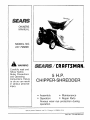
@_/_/,_,@/ CRRFT.SM AN®
OWNERS
MANUAL
5 H.P.
CHIPPER-SHREDDER
MODEL NO.
247.796890
The model number will be found on the model plate, attached to the
frame Always mention the model number when requesting service
or repair parts for your chipper-shredder
All parts listed herein may be ordered from any Sears Service Center
and most Sears stores
WHEN ORDERING REPAIR
ING INFORMATION:
•
•
•
•
HOW TO ORDER
REPAIR PARTS
i u
THE
THE
THE
THE
PARTS,
ALWAYS
GIVE THE FOLLOW-
PART NUMBER
PART DESCRIPTION
MODEL NUMBER
247 796890
NAME OF MERCHANDISE--CHIPPER-SHREDDER
If the parts you need are not stocked locally, your order will be electronically transmitted to a Sears Repair Parts Distribution Center for
handling
illu,
Sears, Roebuck and Co, Chicago,
PRINTED IN U S A
tlt 60684 U S A
PART NO 770-5875B
(248.650-099)
8187