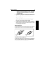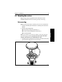
1
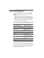
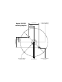
Raystar 120 &
Raystar 112LP
GPS Receivers
Owner’s
Handbook
Document Number: 81203-1
Date: January 2002
Handbook information
To the best of our knowledge, the information in this handbook was
correct when it went to press. However, Raymarine cannot accept
liability for any inaccuracies or omissions it may contain. In addition, our
policy of continuous product improvement may change specifications
without notice. As a result, Raymarine cannot accept liability for any
differences between the product and the handbook.
Copyright Information
Autohelm®, Raymarine® and SeaTalk® are registered trademarks of
Raymarine Ltd.
Raychart, Raynav and Raystar are trademarks of Raymarine Ltd.
Handbook contents © Raymarine Ltd 2002.
Preface
iii
Contents
About this Handbook .............................................................................................v
Important Information ................................................................. vi
Warranty ...................................................................................... vi
Safety notices ............................................................................... vi
EMC conformance ...................................................................... vi
Chapter 1:
About SD-GPS (RS120 only) ............................................................1
1.1 Satellite Differential GPS on the Raystar 120 ............................... 1
1.2 SD-GPS in North America (WAAS) ............................................ 1
How SD-GPS works ..................................................................... 1
1.3 SD-GPS coverage outside North America ................................... 3
Europe (EGNOS) .......................................................................... 3
Asia (MSAS) ................................................................................ 3
1.4 Accuracy & continuation of broadcast coverage .......................... 3
Chapter 2:
Installation .......................................................................................5
2.1 Planning the installation ............................................................... 5
Parts supplied ................................................................................ 5
Cabling guidelines ........................................................................ 6
Electromagnetic compatibility (EMC) installation guidelines ..... 6
2.2 Selecting a suitable location .......................................................... 8
Receiver location .......................................................................... 8
Cabling route ................................................................................ 8
2.3 Mounting the receiver ................................................................... 9
Pole mounting ............................................................................... 9
Surface mounting ........................................................................ 10
Chapter 3:
NMEA/SeaTalk Connections .........................................................11
3.1 Raystar 120/112LP - NMEA versions ........................................ 11
Using the moulded 6-pin NMEA connector ............................... 11
Using an alternative NMEA connector ....................................... 12
3.2 Raystar 120/112LP - SeaTalk versions ....................................... 12
3.3 Using a connector block .............................................................. 13
Chapter 4:
Product Support & Servicing .......................................................15
4.1 EMC, servicing and safety guidelines ........................................ 15
4.2 Product support ........................................................................... 15
Specifications & Compatibility ..........................................................................17
Raystar 120/112LP specifications .............................................. 17
Raystar 120/112LP compatibility ............................................... 18
iv
Raystar 120 & Raystar 112LP GPS Receivers - Owner’s Handbook
Preface
v
About this Handbook
Welcome
Welcome to the handbook for the Raystar 112LP GPS receiver and
Raystar 120 SD-GPS receiver. This handbook provides installation
details for the following products:
•
•
•
•
Raystar 120 SD-GPS receiver with SeaTalk output (Part no: E32025)
Raystar 120 SD-GPS receiver with NMEA output (Part no: E32026)
Raystar 112LP GPS receiver with SeaTalk output (Part no: E32001)
Raystar 112LP GPS receiver with NMEA output (Part no: E32002)
These products are designed to receive GPS (Global Positioning System)
signals and convert this information to either SeaTalk or NMEA:
•
•
the Raystar 112LP receives standard GPS signals, providing a typical
position accuracy of 15 m (without Selective Availability)
the Raystar 120 uses Satellite Differential GPS (SD-GPS) signals to
provide enhanced typical accuracy of less than 3 m
Note: See Chapter 1: About SD-GPS (RS120 only) for more information
about satellite differential GPS.
This handbook contains four chapters:
Chapter
Contents
Page
Chapter 1: About SD-GPS
(RS120 only)
Explains how Satellite Differential GPS enables
the Raystar 120 to provide enhanced accuracy.
1
Chapter 2: Installation
Explains how to mount the Raystar 112LP and
Raystar 120 receivers.
5
Chapter 3: NMEA/SeaTalk Explains how to connect the Raystar output cable 11
Connections
to your GPS display unit or chartplotter.
Chapter 4: Product
Support & Servicing
Provides product support information for the
Raystar 112LP and Raystar 120.
15
At the end of this handbook we have included product specifications and
compatibility information, a mounting template & warranty information.
Note: This handbook contains important information about installing,
using and maintaining your new Raymarine product. To get the best from
the product, please read this handbook thoroughly.
vi
Raystar 120 & Raystar 112LP GPS Receivers - Owner’s Handbook
Important Information
Before using this product, please read the following information about:
•
•
•
Warranty
Safety notices
EMC conformance
Warranty
To register your new Raymarine product, please take a few minutes to fill
out the warranty card. It is important that you complete the owner
information and return the card to us to receive full warranty benefits.
Safety notices
WARNING: Navigation aid
Although we have designed this product to be accurate and reliable,
many factors can affect its performance. As a result, it should only be
used as an aid to navigation and should never replace common sense
and navigational judgement. Always maintain a permanent watch
so you can respond to situations as they develop.
WARNING: Product installation
This equipment must be installed and operated in accordance with
the instructions contained in this handbook. Failure to do so could
result in poor product performance, personal injury and/or damage
to your boat.
WARNING: Electrical safety
Make sure the power supply is switched off before you make any
electrical connections.
WARNING: Servicing
There are no user-serviceable parts in this unit. Do NOT attempt to
open the unit or service the equipment. If the unit develops a fault,
return it to your nearest distributor for service.
EMC conformance
All Raymarine equipment and accessories are designed to the best
industry standards for use in the recreational marine environment. The
design and manufacture of Raymarine equipment and accessories
conform to the appropriate Electromagnetic Compatibility (EMC)
standards, but correct installation is required to ensure that performance
is not compromised.
Chapter 1: About SD-GPS (RS120 only)
1
1.1 Satellite Differential GPS on the Raystar 120
The Raystar 120 Satellite Differential GPS (SD-GPS) Receiver uses the
new satellite differential system to improve the accuracy, integrity and
availability of the basic GPS signals. This provides greater positional
accuracy compared with standard GPS receivers (e.g. Raystar 112LP).
Three separate and compatible SD-GPS systems currently exist or are
being developed:
1. Wide Area Augmentation System (WAAS), developed by the
Federal Aviation Administration (FAA).
2. European Geostationary Navigation Overlay System (EGNOS),
being developed by a European consortium.
3. MTSAT Satellite-Based Augmentation System (MSAS), being
developed by the Japan Civil Aviation Bureau (JCAB).
1.2 SD-GPS in North America (WAAS)
How SD-GPS works
The following description is based on WAAS, but the same principles
apply to the EGNOS and MSAS networks.
As shown in Figure 1-1, the WAAS network consists of:
•
•
•
ground reference stations across the USA
master stations located at East Coast and West Coast
two geostationary satellites located above the equator
This network operates in conjunction with the existing GPS satellites.
The ground reference stations are located at known positions and receive
data continuously from the GPS satellites. The ground reference stations
transmit their data to the master stations, which calculate the error of the
GPS-received positions and generate correctional data.
The master stations send their corrected ‘differential’ signals to the two
geostationary satellites which broadcast the corrected data on the
standard GPS frequency.
1 About SD-GPS (RS120 only)
Chapter 1: About SD-GPS (RS120 only)
Raystar 120 & Raystar 112LP GPS Receivers - Owner’s Handbook
1 About SD-GPS (RS120 only)
2
D4903-1
Figure 1-1: The WAAS System
Your Raystar 120 SD-GPS Receiver can then use this correctional data to
refine the GPS positional data it receives. This results in improved
accuracy (typically less than 3 metres) compared with standard GPS
(typically 15 m) or land-based DGPS (typically 10 m).
Availability of WAAS in North America
The area coverage of WAAS includes the entire United States of America
(see Figure 1-2).
135˚E
150˚E
165˚E
180˚
165˚W
150˚W
135˚W
120˚W
105˚W
90˚W
75˚W
60˚W
45˚W
30˚W
15˚W
0˚
15˚E
75˚N
60˚N
45˚N
30˚N
15˚N
0˚
15˚S
D4910-1
Figure 1-2: WAAS Coverage Map
Chapter 1: About SD-GPS (RS120 only)
3
Information about the status of WAAS and any planned outages are
available via the Raymarine website at:
http://www.raymarine.com
1.3 SD-GPS coverage outside North America
As well as being WAAS compatible, the Raystar 120 is also compatible
with the SD-GPS networks being developed for Europe (EGNOS) and
Asia (MSAS). The combination of the WAAS, EGNOS and MSAS
systems will provide global satellite based differential GPS
augmentation into the future.
Europe (EGNOS)
At the time of going to print, EGNOS was in early testing and
qualification phases. As a result, signal outages may occur at any time.
The status of EGNOS and any planned outages are available on-line at
the Raymarine website:
http://www.raymarine.com
Satellite differential is currently disabled outside the WAAS reception
area. When EGNOS is qualified for navigational use, we will publish a
procedure on the Raymarine website to enable EGNOS operation.
Asia (MSAS)
An Asian satellite differential system (MSAS) is also being developed.
When MSAS is qualified for navigational use, we will publish a
procedure on the Raymarine website to enable MSAS operation.
1.4 Accuracy & continuation of broadcast coverage
CAUTION:
The navigational accuracy of equipment using these satellite
broadcast SD signals during the testing and qualification phases is
not guaranteed by Raymarine Limited, nor is the continuation of the
broadcast SD signals the responsibility of Raymarine Limited.
1 About SD-GPS (RS120 only)
At the time of going to print, WAAS was being tested for aviation use.
During this testing and certification period, continuous service is
expected although brief signal outages may occur as refinements and
upgrades are made to the system.
1 About SD-GPS (RS120 only)
4
Raystar 120 & Raystar 112LP GPS Receivers - Owner’s Handbook
Chapter 2: Installation
5
Chapter 2: Installation
The sections in this chapter explain how to install the Raystar 120/112LP
receivers:
Section
Page
Section 2.1, Planning the installation
5
Section 2.2, Selecting a suitable location
8
Section 2.3, Mounting the receiver
9
2.1 Planning the installation
Before starting to install the Raystar 120/112LP, read through the
following information about:
•
•
•
Parts supplied
Cabling guidelines
Electromagnetic compatibility (EMC) installation guidelines
Parts supplied
The Raystar 120/112LP package contains the following items:
1.
2.
3.
4.
5.
Low profile GPS Receiver, with10 m (33 ft) cable
Flush mount gasket
Mounting studs (x2) and thumb nuts (x2)
Pole mount kit *
Owner’s Handbook (includes warranty documents)
Note: * If you intend to mount the receiver on a pole, you will need to
obtain a suitable pole with 1 inch 14 TPI thread.
2 Installation
CAUTION:
Before starting installation ensure you have the correct unit for your
application.The Raystar 120/112LP compatibility table on page 18
identifies the correct version of the Raystar 120/112LP Receiver for
compatible Raymarine, Autohelm and Apelco units. Raymarine
cannot be held responsible for incorrect operation due to incorrect
unit specification. Always state which model you have when
contacting Raymarine or a registered service agent.
6
Raystar 120 & Raystar 112LP GPS Receivers - Owner’s Handbook
Items missing?
If any of the pack items is missing or damaged, please contact your
Raymarine dealer or our Technical Services Department to obtain
replacement parts. Please note that missing or damaged items cannot
be replaced without proof of purchase.
Cabling guidelines
When running cable, always observe the following guidelines:
2 Installation
•
•
•
•
if a cable has to be fed through the deck, use a good quality deck gland
where cables are fed through holes, use grommets to prevent chafing
secure long cable runs so they do not present a hazard
wherever possible, route cables away from fluorescent lights, engines
and radio transmitting equipment, as these may cause interference
Electromagnetic compatibility (EMC) installation
guidelines
All Raymarine equipment and accessories are designed to the best
industry standards for use in the recreational marine environment.Their
design and manufacture conforms to the appropriate Electromagnetic
Compatibility (EMC) standards, but correct installation is required to
ensure that performance is not compromised. Although every effort has
been taken to ensure that they will perform under all conditions, it is
important to understand what factors could affect the operation of the
product.
The guidelines given here describe the conditions for optimum EMC
performance, but it is recognized that it may not be possible to meet all of
these conditions in all situations. To ensure the best possible conditions
for EMC performance within the constraints imposed by any location,
always ensure the maximum separation possible between different items
of electrical equipment.
For optimum EMC performance, we recommended that wherever
possible:
•
Raymarine equipment and cables connected to it are:
• At least 3 ft (1 m) from any equipment transmitting or cables
carrying radio signals e.g. VHF radios, cables and antennas. In the
case of SSB radios, the distance should be increased to 7 ft (2 m).
Chapter 2: Installation
7
•
•
•
•
Suppression ferrites
The following illustration shows typical cable suppression ferrites used with
Raymarine equipment. Always use the ferrites supplied by Raymarine.
D3548-2
Connections to other equipment
If your Raymarine equipment is to be connected to other equipment using
a cable not supplied by Raymarine, a suppression ferrite MUST always
be attached to the cable near to the Raymarine unit.
2 Installation
More than 7 ft (2 m) from the path of a radar beam. A radar beam
can normally be assumed to spread 20 degrees above and below
the radiating element.
The equipment is supplied from a separate battery from that used for
engine start. Voltage drops below 10 V, and starter motor transients,
can cause the equipment to reset. This will not damage the
equipment, but may cause the loss of some information and may
change the operating mode.
Raymarine specified cables are used. Cutting and rejoining these
cables can compromise EMC performance and must be avoided
unless doing so is detailed in the installation manual.
If a suppression ferrite is attached to a cable, this ferrite should not be
removed. If the ferrite needs to be removed during installation it must
be reassembled in the same position.
8
Raystar 120 & Raystar 112LP GPS Receivers - Owner’s Handbook
2.2 Selecting a suitable location
Receiver location
The Raystar 120/112LP receiver is designed to receive the signals
emitted from satellites in a direct path. It should be mounted:
•
•
2 Installation
•
On a horizontal surface.
In a location that is open and clear of any obstructions (such as
masts, search lights, or other structures) that could block line-of-sight
reception of signals.
As low as possible: the height of the receiver is not as important as it
having a clear view horizon to horizon for optimum signal reception.
In fact, the lower the unit can be mounted and have a clear view to
satellites, the better. The more stable the unit, the more effectively it
will track satellites low to the horizon.
Note: Do NOT mount the receiver up a mast, as the receiver will swing
with the boat, leading to significant COG/SOG errors.
•
As far as possible from any sources of interference: the receiver
should be separated by at least 1 m (3 ft) from other antennas and
electronic equipment. It should not be mounted in the direct path of a
radar’s beam.
Mounting options
You can mount the Raystar 120/112LP on a pole or flush on a suitable
horizontal surface. When mounting the receiver flush to a surface:
•
•
select a suitable area which allows access to the underside of the
mounting surface for fixing
avoid areas where the receiver might be trodden upon or where it
might present a tripping hazard
Cabling route
When planning the location for the unit, consider the best route for
running the cable between the receiver and GPS display unit or to the rest
of an integrated system. Ideally, you should try to route the cable so it is:
•
•
hidden from view
separated as far as possible from other cables (to prevent interference)
Chapter 2: Installation
9
2.3 Mounting the receiver
When you have selected a suitable location, follow the relevant
installation instructions for Pole mounting or Surface mounting.
Pole mounting
Note: You will need to obtain a suitable pole with 1 inch 14 TPI thread.
Note: If you intend to use the side exit channel, remove the two plastic
tabs obstructing the channel. If you do not remove these tabs before
using the cable channel, you could damage the cable.
3. Check the cable is positioned correctly, then secure the receiver to the
pole mount base using the two screws provided.
.
C
B
A
D5898-1
Figure 2-1: Pole mounting
2 Installation
1. Securely attach the pole mount base to a suitable pole or rail mount
bracket.
2. Pass the cable through either:
A: the center hole of the pole mount base, or
B: the cable exit hole alongside the center hole, or
C: the side exit channel
10
Raystar 120 & Raystar 112LP GPS Receivers - Owner’s Handbook
Surface mounting
2 Installation
1. Use the template supplied in this handbook to mark the two 6 mm
(0.25 in) fixing holes. and then drill
2. OPTION A:
If the cable is going to pass through the mounting surface drill either:
• 6 mm (0.25 in) center hole (for bare-ended SeaTalk cables), or
• 19 mm (0.75 in) center hole (for NMEA plugged cables)
OPTION B:
If the cable is going to exit from the side of the receiver above the
mounting surface, remove the two plastic tabs (1) obstructing the
cable channel. If you do not remove these tabs before using the
cable channel, you could damage the cable.
3. Screw the two mounting studs (2) into the underside of the receiver.
4. Stick the supplied gasket (3) to the mounting surface, ensuring that
the holes on the gasket correspond with the drilled holes
5. Pass the cable down through the center hole (Option A) or route it
through the cable exit channel (Option B).
6. Carefully position the receiver so the mounting studs pass through the
holes in the mounting surface.
7. Secure the receiver to the surface using the two thumb nuts (4).
A
B
1
2
3
2
3
4
4
Top view
Underside view
Figure 2-2: Surface mounting
D5897-1
Chapter 3: NMEA/SeaTalk Connections
11
Chapter 3: NMEA/SeaTalk Connections
The sections in this chapter explain how to connect the NMEA and
SeaTalk versions of the Raystar 120/112LP to other equipment:
Section
Page
Section 3.1, Raystar 120/112LP - NMEA versions
11
Section 3.2, Raystar 120/112LP - SeaTalk versions
12
Section 3.3, Using a connector block
13
3.1 Raystar 120/112LP - NMEA versions
Note: As with all on-board marine equipment, you must ensure that the
power supply connection to the Raystar 120/112LP is adequately
protected by a suitably rated fuse or circuit breaker. Usually this will be
achieved by providing power via a fused display unit.
Using the moulded 6-pin NMEA connector
NMEA connector
3 Screen (0 V/ground)
2 Screen
(0 V/ground)
4 Yellow
(NMEA out)
1 Red
(Power )
5 Green
(NMEA in)
6 Brown (RTCM in)
D5899-1
Figure 3-1: NMEA connector pin-outs
3 NMEA/SeaTalk Connections
The unit is normally connected to an NMEA system via the 10 m (33 ft)
cable terminated with a moulded 6-pin connector (see Figure 3-1). Use
this connector if your equipment has a compatible GPS port.
12
Raystar 120 & Raystar 112LP GPS Receivers - Owner’s Handbook
Using an alternative NMEA connector
If your equipment is not compatible with the supplied connector, remove
it and then either:
•
•
use a connector block to re-connect the cable
connect the cable to another type of NMEA connector.
Refer to Table 3-1 for information about cable colors. The cable can be
cut as necessary to the required length, or coiled and stored out of the way.
Note: Insulate and tape back any unused wires.
3 NMEA/SeaTalk Connections
Table 3-1: Raystar 120/112LP NMEA cable colors
Pin No
Color
Function
1
Red
Power
2&3
Screen
0 V / ground
4
Yellow
NMEA out
5
Green
NMEA in
6
Brown
RTCM in
3.2 Raystar 120/112LP - SeaTalk versions
The SeaTalk versions of the Raystar 120/112LP have a 10 m (33 ft) cable
with bare ends. Use this cable to connect to your existing SeaTalk bus,
using the cable color information detailed in Figure 3-2.
SeaTalk cable
Red (12 V)
Yellow (SeaTalk input/output)
Brown (RTCM in)
Green (Not used)
Screen (0 V/ground)
D5900-1
Figure 3-2: SeaTalk cable connections
Chapter 3: NMEA/SeaTalk Connections
13
3.3 Using a connector block
When connecting a Raystar 120/112LP into an existing instrument
system or to certain Raymarine chartplotters (e.g. Raychart 630), you can
use a connector block to:
•
•
connect into the SeaTalk bus
supply power to the SeaTalk bus for this and other applications (if DC
power is not already available via an existing SeaTalk instrument)
Figure 3-3 shows how you can use a connector block to make the
interconnections between the Raystar 120/112LP, the SeaTalk bus and,
if required, an external DC power supply.
CAUTION:
Use a multimeter (set to an appropriate range) to check correct
polarity and connections to the 12 V DC supply before you apply
power to the Raystar receiver.
0V
RTCM
RTCM in (if used)
Black
Red
To SeaTalk
(typical plug shown)
Screen
Screen
Terminal
Brown
1 (0 V)
0V
12 V
Power
Supply
To RS120
or RS112LP:
0 V: 1
12 V: 2
Data: 3
3 (SeaTalk)
Black
Red
12 V
Fused
Red
Yellow
Yellow
Cable
SeaTalk
Power
RS120 or
RS112LP
Wire colour
Screen
Red
Yellow
Black
Red
Screen
Red
Yellow
Brown
Green
Terminal
1
2
3
1
2
1
2
3
-
Green
(not used)
Function
0V
12 V
SeaTalk
0V
12 V
0V
12 V
SeaTalk
RTCM in
Not used
D5901-1
Figure 3-3: NMEA/SeaTalk wiring interconnections
Note: You can obtain a suitable SeaTalk Auxiliary Junction Box from
your Raymarine agent. It is supplied with certain chartplotter products.
3 NMEA/SeaTalk Connections
2 (12 V)
14
Raystar 120 & Raystar 112LP GPS Receivers - Owner’s Handbook
NMEA inputs/outputs
Information transfer between units is determined by various data
sentences transferred via NMEA as detailed in Table 3-2.
Table 3-2: NMEA sentences
NMEA sentences
Output sentences
GPGGA, GPGSA, GPGSV, GPGLL, GPRMC, GPDTM, GPVTG,
PRAYA
Input sentences
PRAYI, PRAYE, PRAYA
For further technical information, please visit the Raymarine web site at:
3 NMEA/SeaTalk Connections
http://www.raymarine.com
Chapter 4: Product Support & Servicing
15
Chapter 4: Product Support & Servicing
All Raymarine products are designed to provide many years of
trouble-free operation. We also put them through comprehensive testing
and quality assurance procedures before shipping.
CAUTION:
The Raystar 112LP and Raystar 120 receivers DO NOT contain
user-serviceable parts. They should be serviced only by authorized
Raymarine service technicians.
4.1 EMC, servicing and safety guidelines
•
•
•
•
•
4.2 Product support
Raymarine products are supported by a worldwide network of
distributors and Authorized Service Representatives. If you encounter
any difficulties with this product, please contact either your national
distributor, or your service representative, or the Raymarine Technical
Services Call Center. Refer to the back cover or the Worldwide
Distributor List for contact details.
4 Product Support & Servicing
Raymarine equipment should be serviced only by authorized Raymarine service technicians. They will ensure that service procedures and
replacement parts used will not affect performance. There are no user
serviceable parts in any Raymarine product.
Some products generate high voltages: never handle the cables/connectors when power is being supplied to the equipment.
When powered up, all electrical equipment produces electromagnetic fields. These can cause adjacent pieces of electrical equipment
to interact with one another, with a consequent adverse effect on operation. In order to minimize these effects and enable you to get the best
possible performance from your Raymarine equipment, guidelines
are given in the installation instructions, to enable you to ensure minimum interaction between different items of equipment, i.e. ensure
optimum Electromagnetic Compatibility (EMC).
Always report EMC-related problems to your nearest Raymarine
dealer. We use such information to improve our quality standards.
In some installations, it may not be possible to prevent the equipment
from being affected by external influences. In general this will not
damage the equipment but it can lead to spurious resetting action, or
momentarily may result in faulty operation.
4 Product Support & Servicing
16
Raystar 120 & Raystar 112LP GPS Receivers - Owner’s Handbook
Specifications & Compatibility
Specifications & Compatibility
Raystar 120/112LP specifications
Raystar 120 and 112LP
Receiver type:
Raystar 112LP: GPS, 12 parallel channels
Raystar 120: SD-GPS, WAAS/EGNOS/MSAS ready, 12 parallel channels
Frequency:
1575.42 MHz ±1 MHz (C/A code), L1
Sensitivity:
-130 dBm
Signal acquisition:
Automatic
Time to first fix (TTTF):
< 8 seconds (typical); < 45 seconds from cold start (average)
Position accuracy:
Raystar 112LP: <15 m 95% (L1, C/A code HDOP < 2 without SA)
Raystar 120 (with WAAS/EGNOS/MSAS): <3 m 95% (L1, C/A code
HDOP < 2 without Selective Availability)
Speed accuracy:
0.1 kts RMS (L1, C/A code HDOP < 2.5 without Selective Availability)
Geodetic datum:
WGS-84 (227 selectable alternatives)
Power requirement:
NMEA versions: 9 V to 30 V NMEA @ 1.5 Watts
SeaTalk versions: 9 V to 18 V SeaTalk @ 1.5 Watts
Data input/output:
NMEA versions: NMEA 0183 Ver2.3 output; non-isolated NMEA input;
RTCM SC-104 Ver 2.1 input.
SeaTalk versions: SeaTalk bus; RTCM SC-104 Ver 2.1 input
Operating conditions:
temperature range: -10°C to 70°C (14°F to 158°F)
water protection: waterproof to CFR46
Storage conditions:
temperature range: -10°C to 70°C (14°F to 158°F)
Cable length:
10 m (33 ft)
Dimensions:
diameter: 95 mm (3.7 in)
height: 30 mm (1.2 in); 62 mm (2.4 in) with pole mount kit
Weight:
0.435 kg (15.3 oz)
Memory backup:
Lithium battery (10 year life)
CE approvals - conforms to:
89/336/EC (EMC), EN60945:1997
CAUTION:
Take care when disposing of this unit, as it contains a lithium battery. You must
follow any local regulations relating to the disposal of hazardous materials.
17
18
Raystar 120 & Raystar 112LP GPS Receivers - Owner’s Handbook
Raystar 120/112LP compatibility
The Raystar 120 and 112LP receivers are available in two versions:
SeaTalk or NMEA. Each version is easily identified with NMEA or
SEATALK printed on the top of the receiver case.
•
NMEA versions of the Raystar 120 (Part no: E32026) and 112LP
(Part no: E32002) receivers can be used to replace the Raystar 100,
900, 105, 108, 112, Apelco 1100, 180,182 and 182XT GPS antennas
Seatalk versions of the Raystar 120 (Part no: E32025) and 112LP
(Part no: E32001) can be used to replace the Autohelm Black Box
Z146, Autohelm Z197 and Z260 GPS antennas
•
The following table identifies the recommended Raystar 120 or 112LP
receiver version for compatible Raymarine, Autohelm and Apelco units.
.
Raystar 120 NMEA (E32026)
Raystar 112LP NMEA (E32002)
Raystar 120 SeaTalk (E32025)
Raystar 112LP SeaTalk (E32001)
NAV298, 398
Autohelm ST50 GPS*
Raynav 575
Autohelm ST50 Navdata*
Raystar 390, 790
Autohelm ST80 GPS (Masterview/
Navigator)
Fishfinder V850, 8010
Autohelm Navcenter 300*, 500*, 700*
Raychart 600*, 610*, 611*, 620*, 630*
Fishfinder L755*, L760*
Raychart 420
Raychart 520*, 530*, 631*
Autohelm Navcenter 600*
Pathfinder (LCD) RL70*, RL70RC*,
RL70C*, RL70CRC*, RL80*, RL80RC*
Apelco 530, 560
Pathfinder (CRT) R70*, R70RC*, R80*,
R80RC*
Apelco 6400, 6700, 6760, 6800, 7000
Apelco GXL 1100
*Model is both Seatalk and NMEA compatible, however the recommended RS120 or
RS112LP version should be used for complete functionality and to simplify installation.
Note: On some earlier units (e.g. Raychart 630) designed before WAAS
and similar systems were available, a satellite differential fix (SD-FIX)
will be reported as D-FIX. In such cases a satellite differential fix will still
be acquired and the enhanced navigational accuracy of the satellite
differential system will still be utilized.
19 mm (0.75 in) diameter
if cable has NMEA plug
36 mm (1.4 in)
18 mm
(0.7 in)
18 mm
(0.7 in)
36 mm (1.4 in)
Raystar 120/112LP
mounting template
D59
6 mm (0.25 in) diameter
if cable has no plug
Cable exit channel
02-1
6 mm (0.25 in) diameter
2 positions
This equipment uses certain elements of software supplied to Raymarine by SiRF Technology Inc., to which the following licence agreement applies. Please read it carefully.
SiRF LICENSE AGREEMENT
IMPORTANT - READ CAREFULLY:
This is a legal agreement (the “Agreement”) between SiRF Technology Incorporated, which has offices
at 3970 Freedom Circle, Santa Clara, California 95054 (“SiRF”) and you. It is important that you read
this document before using the software embedded in the product (the “Software”). By using the
Software, you agree to be bound by these terms and conditions.
1. GRANT OF LICENSE. SiRF grants to you, subject to the terms and
conditions of this Agreement, a non-exclusive, non-transferable
right and license to use the Software only as part of the product in
which it is embedded. You have no other rights to the Software. You
may not copy, modify, disassemble, reverse engineer or decompile
the Software. You agree not to remove, obliterate, or hide any copyright, trademark, confidentiality, patent or other proprietary notice,
mark or legend appearing on the Software or on output generated by
the Software.
5. ASSIGNMENT. This Agreement shall inure to the benefit of and
be binding upon each party's permitted successors and assigns.
6. GOVERNING LAW. The validity, interpretation, construction and
performance of this Agreement shall be governed by the laws of
the State of California, excluding its conflict of laws principles.
2. OWNERSHIP. The Software is licensed, not sold. All right, title and
interest in and to the Software in any form be the sole property of
SiRF and/or its suppliers.
3. LIMITED WARRANTY REMEDIES; DISCLAIMER; LIMITATION OF
LIABILITY
Limited Warranty. SiRF warrants that for a period of ninety (90) days
the Software will be in substantial compliance with SiRF's applicable
written technical documentation for the Software. SiRF shall, at its
option, modify or replace all non-conforming Software. The foregoing remedy for breaches of the Software warranty is your exclusive
remedy, and you hereby waive all other remedies.
7. LEGAL REQUIREMENTS. You may not export, re-export, divert,
transfer or disclose, directly or indirectly the Software and any
related technical information or materials without complying
strictly with all legal requirements. You agree to comply with all
applicable federal, state and local orders, laws, regulations and
ordinances, including specifically United States federal government regulations relating to use of products containing global
positioning systems technology.
Disclaimer of Warranties. THE SOFTWARE IS LICENSED “AS IS.”
EXCEPT AS SET FORTH IN THIS SECTION 3, SiRF DOES NOT REPRESENT OR WARRANT THAT ERRORS IN THE SOFTWARE WILL BE CORRECTED OR THAT THE SOFTWARE WILL RUN UNINTERRUPTED OR
ERROR-FREE. EXCEPT AS SET FORTH IN THIS SECTION 4, THERE ARE
NO WARRANTIES COVERING THE SOFTWARE, EITHER EXPRESS OR
IMPLIED, INCLUDING WITHOUT LIMITATION ANY WARRANTY OF
DESIGN, MERCHANTABLITY, FITNESS FOR A PARTICULAR PURPOSE,
OR AGAINST INFRINGEMENT. NO AGENT OF SiRF IS AUTHORIZED
TO ALTER OR EXCEED THE WARRANTY OBLIGATIONS OF SiRF SET
FORTH IN THIS AGREEMENT.
8. U.S. GOVERNMENT RESTRICTED RIGHTS. The Software and
Documentation are provided with Restricted Rights. Use, duplication, or disclosure by the Government is subject to restrictions as
set forth in this Agreement, pursuant to DFARS 227-7202-3 or subparagraphs (c)(i) and (2) of the Commercial Computer SoftwareRestricted Rights at 48 CFR 52.227-19, as applicable, or as set forth
in the particular department or agency regulations or rules that
provide SiRF with protection equivalent to or greater than the
above-cited clause. The Manufacturer is SiRF Technology Incorporated, 3970 Freedom Circle, Santa Clara, California 95054.
Limitation of Remedies and Liability. TO THE EXTENT PERMITTED
UNDER APPLICABLE LAW, SiRF DISCLAIMS LIABILITY, AND SHALL
NOT BE LIABLE TO YOU, FOR ANY LOSS OF PROFIT, INDIRECT, INCIDENTAL, SPECIAL, PUNITIVE, OR CONSEQUENTIAL DAMAGES
ARISING OUT OF OR RELATING TO USE OF THE PRODUCT OR THE
SOFTWARE. The maximum aggregate liability of SiRF arising out of
this Agreement and any Product or Software, whether such liability
arises from any claim based on breach or repudiation of contract,
warranty, tort or otherwise, shall in no case exceed the actual price of
the product whose license, use or other employment gives rise to the
liability, to the extent such liability may be limited under applicable
law.
9. MISCELLANEOUS. This Agreement contains the entire understanding and agreement between the parties respecting the subject matter hereof and all prior understandings, representations
and agreements of the parties, whether oral or written, with
respect to the subject of this Agreement are superseded in their
entirety. If any provision of this Agreement shall be held by a court
of competent jurisdiction to be illegal, invalid or unenforceable,
the remaining provisions shall remain in full force and effect. This
Agreement may not be supplemented, modified, amended,
released or discharged except by an instrument in writing signed
by each party's duly authorized representative. This Agreement is
in the English language only, which language shall be controlling
in all respects. The rights and obligations of each party to this
Agreement shall not be governed by the provisions of the United
Nations Convention on Contracts for the International Sale of
Goods. If any action at law or in equity, including an action for
declaratory relief or injunctive relief is brought to enforce or interpret the provisions of this Agreement, the prevailing party shall be
entitled to reasonable attorneys' fees in addition to any other relief
to which the party may be entitled. Any waiver by either party of
any default or breach hereunder shall not constitute a waiver of
any provision of this Agreement or of any subsequent default or
breach of the same or a different kind.
4. TERM AND TERMINATION. This Agreement shall be effective on
the date that you use the Software, and shall continue in effect until
terminated in accordance with this Section 4. SiRF may terminate
this Agreement for material breach by providing thirty (30) days written notice to you. Upon termination of this Agreement, all rights
granted by this Agreement shall revert to SiRF, and you shall cease
and desist all use of the Software. The following provisions of this
Agreement shall survive its termination: Sections 2 through 11.
Limited Warranty Certificate
Raymarine warrants each new Light Marine/Dealer Distributor Product to be of good materials and
workmanship, and will repair or exchange any parts proven to be defective in material and
workmanship under normal use for a period of 2 years/24 months from date of sale to end user, except
as provided below.
Defects will be corrected by Raymarine or an authorized Raymarine dealer. Raymarine will, except
as provided below, accept labor cost for a period of 2 years/24 months from the date of sale to end user.
During this period, except for certain products, travel costs (auto mileage and tolls) up to 100 round
trip highway miles (160 kilometres) and travel time of 2 hours, will be assumed by Raymarine only
on products where proof of installation or commission by authorized service agents, can be shown.
Warranty Limitations
Raymarine Warranty policy does not apply to equipment which has been subjected to accident, abuse
or misuse, shipping damage, alterations, corrosion, incorrect and/or non-authorized service, or
equipment on which the serial number has been altered, mutilated or removed.
Except where Raymarine or its authorized dealer has performed the installation, it assumes no
responsibility for damage incurred during installation.
This Warranty does not cover routine system checkouts or alignment/calibration, unless required by
replacement of part(s) in the area being aligned.
A suitable proof of purchase, showing date, place, and serial number must be made available to
Raymarine or authorized service agent at the time of request for Warranty service.
Consumable items, (such as: Chart paper, lamps, fuses, batteries, styli, stylus/drive belts, radar mixer
crystals/diodes, snap-in impeller carriers, impellers, impeller bearings, and impeller shaft) are
specifically excluded from this Warranty.
Magnetrons, Cathode Ray Tubes (CRT), TFT Liquid Crystal Displays (LCD) and cold cathode
fluorescent lamps (CCFL), hailer horns and transducers are warranted for 1 year/12 months from date
of sale. These items must be returned to a Raymarine facility.
All costs associated with transducer replacement, other than the cost of the transducer itself, are
specifically excluded from this Warranty.
Overtime premium labor portion of services outside of normal working hours is not covered by this
Warranty.
Travel cost allowance on certain products with a suggested retail price below $2500.00 is not
authorized. When/or if repairs are necessary, these products must be forwarded to a Raymarine
facility or an authorized dealer at owner’s expense will be returned via surface carrier at no cost to the
owner.
Travel costs other than auto mileage, tolls and two (2) hours travel time, are specifically excluded on
all products. Travel costs which are excluded from the coverage of this Warranty include but are not
limited to: taxi, launch fees, aircraft rental, subsistence, customs, shipping and communication
charges etc. Travel costs, mileage and time, in excess to that allowed must have prior approval in
writing.
TO THE EXTENT CONSISTENT WITH STATE AND FEDERAL LAW:
(1) THIS WARRANTY IS STRICTLY LIMITED TO THE TERMS INDICATED HEREIN, AND
NO OTHER WARRANTIES OR REMEDIES SHALL BE BINDING ON RAYMARINE
INCLUDING WITHOUT LIMITATION ANY WARRANTIES OF MERCHANTABLE OR
FITNESS FOR A PARTICULAR PURPOSE.
(2) Raymarine shall not be liable for any incidental, consequential or special (including punitive or
multiple) damages.
All Raymarine products sold or provided hereunder are merely aids to navigation. It is the
responsibility of the user to exercise discretion and proper navigational skill independent of any
Raymarine equipment.
Document number: 84064-8
April 2001
Factory Service Centers
United States of America
UK, Europe, Middle East, Far East
Raymarine Inc
22 Cotton Road, Unit D
Nashua, NH 03063-4219, USA
Raymarine Ltd
Anchorage Park, Portsmouth
PO3 5TD, England
Telephone: +1 603 881 5200
Fax: +1 603 864 4756
www.raymarine.com
Telephone: +44 (0)23 9269 3611
Fax: +44 (0)23 9269 4642
www.raymarine.com
Sales & Order Services
Telephone: +1 800 539 5539 Ext. 2333 or
+1 603 881 5200 Ext. 2333
Customer Support
Telephone: +44 (0)23 9271 4713
Fax: +44 (0)23 9266 1228
Technical Support
Telephone: +1 800 539 5539 Ext. 2444 or
+1 603 881 5200 Ext. 2444
Email: [email protected]
Email: [email protected]
Product Repair Center
Telephone: +1 800 539 5539 Ext. 2118
Stick barcode label here
Purchased from
Purchase date
Dealer address
Installed by
Installation date
Commissioned by
Commissioning date
Owner’s name
Mailing address
This portion should be completed and retained by the owner.