1
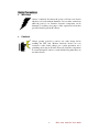
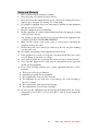
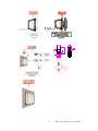
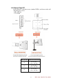
IC70-series Panel PC
Intel® i5/i7 800/1066 MHz Mini-ITX SBC,
High Performance Design with Intel
HM55 Platform, CRT/LCD/TV and
versatile expansions.
User Guide Version 1.0
FCC Statement
This device complies with part 15 FCC rules. Operation is subject to
the following two conditions:
This device may not cause harmful interference.
This device must accept any interference received including
interference that may cause undesired operation.
This equipment has been tested and found to comply with the limits for a class "a"
digital device, pursuant to part 15 of the FCC rules. These limits are designed to
provide reasonable protection against harmful interference when the equipment is
operated in a commercial environment. This equipment generates, uses, and can
radiate radio frequency energy and, if not installed and used in accordance with the
instruction manual, may cause harmful interference to radio communications.
Operation of this equipment in a residential area is likely to cause harmful
interference in which case the user will be required to correct the interference at him
own expense.
II
IC70 series Panel PC User Guide
Copyright Notice
ALL RIGHTS RESERVED. No part of this document may be reproduced, copied,
translated, or transmitted in any form or by any means, electronic or mechanical, for
any purpose, without the prior written permission of the original manufacturer.
Trademark Acknowledgement
Brand and product names are trademarks or registered trademarks of their respective
owners.
Disclaimer
We reserve the right to make changes, without notice, to any product, including
circuits and/or software described or contained in this manual in order to improve
design and/or performance. We Communication assumes no responsibility or liability
for the use of the described product(s), conveys no license or title under any patent,
copyright, or masks work rights to these products, and makes no representations or
warranties that these products are free from patent, copyright, or mask work right
infringement, unless otherwise specified. Applications that are described in this
manual are for illustration purposes only. We Communication Inc. makes no
representation or warranty that such application will be suitable for the specified use
without further testing or modification.
Warranty
We warrant that each of its products will be free from material and workmanship
defects for a period of one year from the invoice date. If the customer discovers a
defect, We will, at its option, repair or replace the defective product at no charge to
the customer, provided it is returned during the warranty period of one year, with
transportation charges prepaid. The returned product must be properly packaged in it’s
original packaging to obtain warranty service.
If the serial number and the product shipping data differ by over 30 days, the
in-warranty service will be made according to the shipping date. In the serial numbers
the third and fourth two digits give the year of manufacture, and the fifth digit means
the month (e. g., with A for October, B for November and C for December).
For example, the serial number 1W07Axxxxxxxx means October of year 2007.
III
IC70 series Panel PC User Guide
Check List
Before using this Panel PC, please make sure that all the items listed below
are present in your package
1 x IC70 series Panel PC
1 x IC70 series Panel PC User Guide
1 x IC70 SBC User Manual
1 x Power adapter
1 x CD-ROM disc with Driver Utility and User's Manual
Make sure that all of the items listed above are present. Do not attempt to
apply power to the system if there is damage to any of its components.
Customer Service
We provide service guide for any problem as follow steps:First, visit the website at
http://www.we.com to find the update information about the product. Second, contact
with your distributor, sales representative, or our customer service center for technical
support if you need additional assistance. You may have the following information
ready before you call:
Product serial number
Peripheral attachments
Software (OS, version, application software, etc.)
Description of complete problem
The exact wording of any error messages
In addition, free technical support is available from our engineers every business day.
We are always ready to give advice on application requirements or specific
information on the installation and operation of any of our products. Please do not
hesitate to call or e-mail us.
Notice
1. Do not touch the LCD panel surface with sharp or hard objects.
2. Do not use abrasive cleaners, waxes or solvents for cleaning, use only a dry
or damp, soft cloth.
3. Use only with a high quality, safety-approved, AC/DC power adapter.
IV
IC70 series Panel PC User Guide
Safety Precautions
Warning!
Always completely disconnect the power cord from your chassis
whenever you work with the hardware. Do not make connections
while the power is on. Sensitive electronic components can be
damaged by sudden power surges. Only experienced electronics
personnel should open the PC chassis.
Caution!
Always ground yourself to remove any static charge before
touching the CPU card. Modern electronic devices are very
sensitive to static electric charges. As a safety precaution, use a
grounding wrist strap at all times. Place all electronic components
in a static-dissipative surface or static-shielded bag when they are
not in the chassis.
V
IC70 series Panel PC User Guide
Safety and Warranty
1.
2.
3.
Please read these safety instructions carefully.
Please keep this user's manual for later reference.
Please disconnect this equipment from any AC outlet before cleaning. Do not use
liquid or spray detergents for cleaning. Use a damp cloth.
4. For pluggable equipment, the power outlet must be installed near the equipment
and must be easily accessible.
5. Keep this equipment away from humidity.
6. Put this equipment on a reliable surface during installation. Dropping it or letting
it fall could cause damage.
7. The openings on the enclosure are for air convection. Protect the equipment from
overheating. DO NOT COVER THE OPENINGS.
8. Make sure the voltage of the power source is correct before connecting the
equipment to the power outlet.
9. Position the power cord so that people cannot step on it. Do not place anything
over the power cord.
10. All cautions and warnings on the equipment should be noted.
11. If the equipment is not used for a long time, disconnect it from the power source
to avoid damage by transient over-voltage.
12. Never pour any liquid into an opening. This could cause fire or electrical shock.
13. Never open the equipment. For safety reasons, only qualified service personnel
should open the equipment.
14. If any of the following situations arises, get the equipment checked by service
personnel:
A. The power cord or plug is damaged.
B. Liquid has penetrated into the equipment.
C. The equipment has been exposed to moisture.
D. The equipment does not work well, or you cannot get it to work according to
the user’s manual.
E. The equipment has been dropped and damaged.
F. The equipment has obvious signs of breakage.
15. Do not leave this equipment in an uncontrolled environment where the storage
temperature is below -20° C (-4°F) or above 60° C (140° F). It may damage the
equipment.
VI
IC70 series Panel PC User Guide
Revision History
Version
Date
1.0
2011.08.16
Note
First Version
VII
Author
Henry Hsu
IC70 series Panel PC User Guide
Contents
CHAPTER 1 GENERAL INFORMATION.........................................................................................1
1-1 Introduction................................................................................................. 1
1-2 IC70 series Panel PC System Specifications ................................................ 2
1-3 LCD Selection Guide................................................................................... 3
CHAPTER 2 GETTING STARTED.....................................................................................................4
2-1 Input / Output Devices................................................................................. 4
2-2 Starting the Panel PC& O/S Installation....................................................... 5
2-3 Driver Installation........................................................................................ 5
CHAPTER 3 TOUCH DRIVER INSTALLATION.............................................................................6
3-1 Introduction................................................................................................. 6
3-2 The ELO AccuTouch Driver Installation...................................................... 7
3-2-1 Configuration Utility ........................................................................ 8
3-3 The Premier Touch Driver Installation ....................................................... 10
3-3-1 Configuration Utility .......................................................................11
CHAPTER 4 IC70 SERIES PANEL PC MOUNTING GUIDE ....................................................... 13
4-1 Open Frame Panel PC:............................................................................... 13
4-2 5mm Panel Mount Panel PC: ..................................................................... 15
4-3 10mm IP65 Panel PC................................................................................. 17
4-4 Chassis Panel PC ....................................................................................... 19
Chapter 1 GENERAL INFORMATION
1-1 Introduction
The IC70 series Panel PC is high performance PC with Intel® HM55 chipset
which combines with a TFT LCD Panel. The Intel® i5/i7 high performance
Processor delivers the most performance per watt available in the market. The
Panel PC is designed to satisfy most of the applications in the industrial market,
such as POS, KIOSK, Industrial Automation, HMI and Programmable
Control System. It’s a PC-based system with DDR3 SDRAM, VGA/LCD
controller, one RS232 brings power among four COM ports, also a SATA with
+5V power, on-board 10/100/1000 Mpbs Base-T Ethernet. The Panel PC
supports PCI-Ex16/ Mini-PCIe expansion slots for Wireless, Ethernet, COM
port, Graphic card and TV functions. It is a flexible and versatile design over
the demanding performance requirements of today’s business and industrial
applications.
1
IC70 series Panel PC User Guide
1-2 IC70 series Panel PC System Specifications
Form Factor
Mini-ITX
CPU
Intel® i5/i7 800/1066 MHz Processor
Chipset
HM55
Memory
DDR3 1066/800MHz SO-DIMM x 2 Slot (MAX 8GB)
BIOS
AMI UEFI BIOS
Graphic Controller
Integrated Gfx Gen5.75
VGA
Up to 2048 x 1536 @ 75Hz
LVDS
Dual-channel 18/24-bit LVDS Up to 1600 x 1200 @ 60Hz
Ethernet
Dual Broadcom BCM57780 GbE controller
Audio
Realtek ALC886 HD Audio Codec
Serial
2 x RS-232
Serial
1x RS-232/422/485 (Default RS232)
USB
4 x USB
PS/2
2 x PS/2 for Keyboard and Mouse
Power Input
Din 4P 12V DC in
O/S(Optional)
Windows7 Embedded / Windows XP Embedded / Windows XP
Professional / Linux
2
IC70 series Panel PC User Guide
1-3 LCD Selection Guide
The IC70 series Panel PCs support form 10.4-inch to 15-inch TFT Panel w/
touchscreen function, please refer the below:
Item
Size
Resolution
(Recommended)
Display Color
15”
R15IC7T-XXC3
1024 x 768
16.2M colors (RGB 8-bits).
15”
R15IC7T-XXA1
1024 x 768
16.2M colors (RGB 8-bits).
17”
R17IC7T-XXM1
1280 x 1024
16.7M (6bits+FRC)
19”
R19IC7T-XXM1
1280 x 1024
16.7M colors (8bits)
20.1”
R20IC7T-XXA2
1600 x 1200
16.7M colors (8bits)
21.5”
W22IC7T-XXA1
1920 x 1080
16.7M colors (8bits)
3
IC70 series Panel PC User Guide
Chapter 2 Getting Started
2-1 Input / Output Devices
The following figure shows the I/O arrangement of the Panel PC. The backside
of the chassis contains most of the connectors.
5
1
8
4
6
7
3
2
1
Power
On / Off / Reset
Power on/off and Reset the power on your computer.
2
Audio
Audio Jack for Audio (Line-Out, Line-In, Mic-in)
3
USB port
USB-compatible devices can be plugged directly into
the USB 2.0 port.
4
RJ-45 port
Connect a network cable to the standard RJ-45 port and
get connection to the Local Area Network (LAN).
5
COM port
One optional COM port supports RS232/422/485 choice
through jumper setting. COM 1 Provides +5V & +12V
output options by JP1 Jumper setting.
6
VGA port
Use VGA port to connect an external Display.
7
COM port
Two RS-232 connectors build in the rear I/O.
8
PS/2
The Motherboard provides two PS/2 interface. The PS/2
connector supports Keyboard (Green) and Mouse.
4
IC70 series Panel PC User Guide
2-2 Starting the Panel PC& O/S Installation
1.
Connect the power to AC/DC adapter, and connect the power cord to the
AC outlet.
2.
3.
Press the power on switch to start the Panel PC.
Press “DEL” to enter the CMOS setting and check the BIOS setup.
4.
You may install your own O/S if it is not installed.
When installing O/S for this Panel PC, please follow the steps and use external
equipment as Keyboard and Mouse.
(a) Please use external USB DVD-ROM to run the O/S and Driver setting (as
picture showed below).
USB Cable
2-3 Driver Installation
The PPC comes with a User’s Manual and Driver CD that contains most of the
drivers and utilities of your needs.
1. Following the step by step to install Driver (Please refer I771 SBC User’s
Manual Chapter 3, 4, 5, 6) include: Chipset, VGA, Audio, and Ethernet.
2. Following the step by step to install the Touch screen if necessary (Please
refer T series PPC User Guide Chapter 3).
5
IC70 series Panel PC User Guide
Chapter 3 Touch Driver Installation
3-1 Introduction
The PPC supports three kinds of Touch Panel Solutions: ELO AccuTouch touchscreen,
Premier Touch system. Both of the touchscreen system consists of a touchscreen and
an electronic touchscreen controller.
The IC70 series Panel PC’s touch device is used RS232 interface touch controller card
via the COM2 port inside Panel PC. When the touch driver installed either for ELO or
Premier Touch systems, it will detect COM2 port automatically.
The ELO AccuTouch and Premier touchscreen is based on patented resistive
technology. The touchscreen may be a flat, spherical, or cylindrical. It is installed over
the face of the display. Since its shape matches of the display face, the touchscreen
has excellent clarity and minimal parallax.
6
IC70 series Panel PC User Guide
3-2 The ELO AccuTouch Driver Installation
ELO AccuTouch driver software provides a consistent software interface among all
ELO AccuTouch touch screens and controllers.
Go to http://www.elotouch.com/Support/dnld.asp for a complete list of available
drivers.
For Driver Installation, please install the “ELO Touch System Touch Tools CD” for
Windows XP, Windows 2000, Windows Me, Windows 98, Windows 95, Windows NT,
Windows CE 2.x, 3.0, 4.x, Windows XP Embedded, Windows 3.1, DOS, OS/2 Warp,
and Apple Macintosh. Just follow the step by step to install the driver.
Choose “Auto-detect Elo devices ” in the first step. If not, the following step will need
users choose COM2 port for detecting the devices.
7
IC70 series Panel PC User Guide
3-2-1 Configuration Utility
After finishing the installation, please follow the steps to test the configuration utility.
Step.1 Enter “My Computer”, click the “Elo touchscreen” shortcut function.
Step.2 Click “Align” function key to go to next step.
8
IC70 series Panel PC User Guide
Step.3 Correct 4 point locations on screen with the Panel PC. Screen display as
follows.
Step.4 Touch the “yes” function if the cursor follows your finger and finish the utility
test.
9
IC70 series Panel PC User Guide
3-3 The Premier Touch Driver Installation
TouchKit is the Premier Touch software, which contains drivers of the touch panel
controllers for the specified communication connectors, RS232, PS/2 and USB, and
the other two utilities.
The two utilities are as follows:
Touch Tray support
This is utility for emulating the right and left button of mouse through
controlling touch panel. Users can toggle between right or left mouse
buttons by this utility.
Configuration support
The calibration and draw test of touch panel are done by this utility. Besides,
users can add or remove for new RS-232 or PS/2 touch panel devices.
Follow these steps to install TouchKit.
Step.1 Put the TouchKit CD to CD-ROM.
Step.2 Open the Win2000_XP directory.
Step.3 Double click the Setup.exe, then windows starts to run the installation program.
Notice that does not plug the USB controller on the system before the installation has
been finished.
Step.4 Click Next to continue installation. And it will auto-detect touch devices in
COM1 port at your Panel PC.
Step.5 Following the step by step to finish the driver installation.
10
IC70 series Panel PC User Guide
3-3-1 Configuration Utility
After finishing the installation, please follow the steps to test the configuration utility.
Step.1 Click the “TouchKit” shortcut function in the desktop.
Step.2 Enter “General” function and choose the language you need.
Then go to next step.
11
IC70 series Panel PC User Guide
Step.3 Correct 4 point locations on screen with the Panel. Screen display as follows
Step.4 Play “Yes” to continue if 4 points calibration test is fine and finish the test.
12
IC70 series Panel PC User Guide
Chapter 4 IC70 series Panel PC Mounting Guide
The Panel PC is suitable for most of the industrial/commercial application, by
any kind of mounting approach. Three main mounting approaches, such as
Panel Mount / Chassis / Open Frame, are very easy for user to install the Panel
PC. As the pictures guided:
4-1 Open Frame Panel PC:
-Panel is aligned with the same height of the front of open frame metal
housing
-Customers can fix our Panel PC with their own front bezel.
-VESA mount holes are also available for mounting from back side.
13
IC70 series Panel PC User Guide
Panel PC size
15”
17”
19”
VESA Mount Dimension
75 x 75 mm /
100 x 100 mm
75 x 75 mm /
100 x 100 mm
75 x 75 mm /
100 x 100 mm
14
IC70 series Panel PC User Guide
4-2 5mm Panel Mount Panel PC:
-Panel is aligned with the same height of the front of open frame metal
housing.
-Touch/Glass is higher than Open frame metal housing.
-Customers can fix our Panel PC with their fixture (max.12mm)
-VESA mount holes are also available for mounting from back side.
15
IC70 series Panel PC User Guide
16
IC70 series Panel PC User Guide
4-3 10mm IP65 Panel PC
-Touch/Glass is aligned with the same height of the front of open frame
metal housing
-Customers can fix our Panel PC with their fixture by M3 screws.
-VESA mount holes are also available for mounting from back side.
17
IC70 series Panel PC User Guide
18
IC70 series Panel PC User Guide
4-4 Chassis Panel PC
Fix the Panel PC with four screws (standard VESA), and fasten to the wall
with other four screws.
- 100 x 100 mm
- 75 x 75 mm
Panel PC size
15”
17”
19”
VESA Mount Dimension
75 x 75 mm /
100 x 100 mm
75 x 75 mm /
100 x 100 mm
75 x 75 mm /
100 x 100 mm
19
IC70 series Panel PC User Guide