1
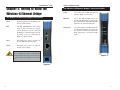
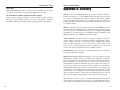
Instant Wireless® Series
Wireless-G Ethernet
Bridge
Use this guide to install:
WET54G
User Guide
COPYRIGHT & TRADEMARKS
Specifications are subject to change without notice. Copyright © 2003 Linksys, All Rights
Reserved. Instant Wireless, Linksys, and the Linksys logo are registered trademarks of
Linksys Group, Inc. Microsoft, Windows, and the Windows logo are registered trademarks of Microsoft Corporation. All other trademarks and brand names are the property
of their respective proprietors.
LIMITED WARRANTY
Linksys guarantees that every Wireless-G Ethernet Bridge will be free from physical
defects in material and workmanship for three years from the date of purchase, when
used within the limits set forth in the Specifications section of this User Guide.
This Warranty is valid and may be processed only in the country of purchase.
If the product proves defective during this warranty period, go to the Linksys website at
www.linksys.com for complete RMA (Return Merchandise Authorization) assistance. You
can also call Linksys Technical Support in order to obtain a RMA Number. BE SURE TO
HAVE YOUR PROOF OF PURCHASE AND A BARCODE FROM THE PRODUCT’S PACKAGING ON HAND WHEN CALLING. RETURN REQUESTS CANNOT BE PROCESSED
WITHOUT PROOF OF PURCHASE. When returning a product, mark the RMA Number
clearly on the outside of the package and include a copy of your original proof of purchase. All customers located outside of the United States of America and Canada shall
be held responsible for shipping and handling charges.
IN NO EVENT SHALL LINKSYS’S LIABILITY EXCEED THE PRICE PAID FOR THE PRODUCT FROM DIRECT, INDIRECT, SPECIAL, INCIDENTAL, OR CONSEQUENTIAL DAMAGES RESULTING FROM THE USE OF THE PRODUCT, ITS ACCOMPANYING SOFTWARE, OR ITS DOCUMENTATION. LINKSYS DOES NOT OFFER REFUNDS FOR ANY
PRODUCT. Linksys makes no warranty or representation, expressed, implied, or statutory, with respect to its products or the contents or use of this documentation and all
accompanying software, and specifically disclaims its quality, performance, merchantability, or fitness for any particular purpose. Linksys reserves the right to revise or
update its products, software, or documentation without obligation to notify any individual or entity. Please direct all inquiries to:
Linksys P.O. Box 18558, Irvine, CA 92623.
SAFETY AND REGULATORY NOTICES
FCC STATEMENT
This Wireless-G Ethernet Bridge has been tested and complies with the specifications for
a Class B digital device, pursuant to Part 15 of the FCC Rules. These limits are designed
to provide reasonable protection against harmful interference in a residential installation.
This equipment generates, uses, and can radiate radio frequency energy and, if not
installed and used according to the instructions, may cause harmful interference to radio
communications. However, there is no guarantee that interference will not occur in a particular installation. If this equipment does cause harmful interference to radio or television
reception, which is found by turning the equipment off and on, the user is encouraged to
try to correct the interference by one or more of the following measures:
•
•
•
•
Reorient or relocate the receiving antenna
Increase the separation between the equipment or devices
Connect the equipment to an outlet other than the receiver’s
Consult a dealer or an experienced radio/TV technician for assistance
FCC Caution: Any change or modification to the product not expressly approved by
Linksys could void the user’s authority to operate the device.
FCC Radiation Exposure Statement
This equipment complies with FCC radiation exposure limits set forth for an uncontrolled
environment. This equipment should be installed and operated with minimum distance
20cm between the radiator and your body.
• Access points with 2.4 GHz or 5 GHz integrated antenna must operate with a separation distance of at least 20 cm from all persons using the cable provided and must
not be co-located or operating in conjunction with any other antenna or transmitter.
End-users must be provided with specific operations for satisfying RF exposure compliance.
Note: Dual antennas used for diversity operation are not considered co-located.
INDUSTRY CANADA (CANADA)
This Class B digital apparatus complies with Canadian ICES-003.
Cet appareil numérique de la classe B est conforme à la norme NMB-003 du Canada.
The use of this device in a system operating either partially or completely outdoors may
require the user to obtain a license for the system according to the Canadian regulations.
EC DECLARATION OF CONFORMITY (EUROPE)
Linksys Group declares that the Instant Wireless Series products included in the Instant
Wireless Series conform to the specifications listed below, following the provisions of the
EMC Directive 89/336/EEC and Low Voltage Directive 73/23/EEC:
•
•
•
ETS 300-826, 301 489-1 General EMC requirements for Radio equipment.
EN 609 50 Safety
ETS 300-328-2 Technical requirements for Radio equipment.
Note: This equipment is intended to be used in all EU and EFTA countries. Outdoor use
may be restricted to certain frequencies and/or may require a license for operation. For
more details, contact Linksys Corporate Compliance.
Note: Combinations of power levels and antennas resulting in a radiated power level of
above 100 mW are considered as not compliant with the above mentioned directive and
are not allowed for use within the European community and countries that have adopted
the European R&TTE directive 1999/5/EC and/or the CEPT recommendation Rec 70.03.
For more details on legal combinations of power levels and antennas, contact Linksys
Corporate Compliance.
•
•
•
Linksys Group vakuuttaa täten että Instant Wireless Wireless-G Ethernet Bridge tyyppinen laite on direktiivin 1999/5/EY, direktiivin 89/336/EEC ja direktiivin 73/23/EEC
oleellisten vaatimusten ja sitä koskevien näiden direktiivien muiden ehtojen
mukainen.
Linksys Group déclare que le pont Ethernet sans fil G est conforme aux conditions
essentielles et aux dispositions relatives à la directive 1999/5/EC, la directive
89/336/EEC, et à la directive 73/23/EEC.
Belgique B L’utilisation en extérieur est autorisé sur le canal 11 (2462 MHz), 12 (2467
MHz), et 13 (2472 MHz).
Dans le cas d’une utilisation privée, à l’extérieur d’un bâtiment, au-dessus d’un
espace public, aucun enregistrement n’est nécessaire pour une distance de moins
de 300m. Pour une distance supérieure à 300m un enregistrement auprès de l’IBPT
est requise. Pour une utilisation publique à l’extérieur de bâtiments, une licence de
l’IBPT est requise. Pour les enregistrements et licences, veuillez contacter l’IBPT.
Wireless-G Ethernet Bridge
•
•
•
•
•
•
•
•
France F: Bande de fréquence restreinte: seuls les canaux 10, 11, 12, 13 (2457,
2462, 2467, et 2472 MHz respectivement) doivent être utilisés en France. Toute utilisation, qu'elle soit intérieure ou extérieure, est soumise à autorisation. Vous pouvez
contacter l'Autorité de Régulation des Télécommuniations (http://www.art-telecom.fr)
pour la procédure à suivre.
France F: Restricted frequency band: only channels 10, 11, 12, 13 (2457, 2462,
2467, and 2472 MHz respectively) may be used in France. License required for
every indoor and outdoor installations. Please contact ART for procedure to follow.
Deutschland D: Anmeldung im Outdoor-Bereich notwending, aber nicht genehmigungspflichtig. Bitte mit Händler die Vorgehensweise abstimmen.
Germany D: License required for outdoor installations. Check with reseller for procedure to follow.
Italia I: E' necessaria la concessione ministeriale anche per l'uso interno. Verificare
con i rivenditori la procedura da seguire. L'uso per installazione in esterni non e' permessa.
Italy I: License required for indoor use. Use with outdoor installations not allowed.
the Netherlands NL License required for outdoor installations. Check with reseller for
procedure to follow.
Nederlands NL Licentie verplicht voor gebruik met buitenantennes. Neem contact op
met verkoper voor juiste procedure.
Table of Contents
Chapter 1: Introduction
The Wireless-G Ethernet Bridge
Features
1
1
1
Chapter 2: Getting to Know the Wireless-G
Ethernet Bridge
The Wireless-G Ethernet Bridge’s Back Panel
The Wireless-G Ethernet Bridge’s Front Panel LEDs
2
2
3
Chapter 3: Planning Your Wireless Network
Network Topology
Ad-Hoc versus Infrastructure Mode
4
4
4
Chapter 4: Connecting the Wireless-G Ethernet
Bridge for Setup
7
Chapter 5: Setting Up the Wireless-G Ethernet
Bridge
8
Chapter 6: Connecting the Wireless-G Ethernet
Bridge for Network Use
Connection to a Network Device
Placement Options
16
16
17
Chapter 7: Using the Wireless-G Ethernet Bridge
Web-based Utility
18
Overview
18
Starting the Web-based Utility
18
Setup
20
Password
25
Advanced
26
Status
29
Help
31
Appendix A: Troubleshooting
Common Problems and Solutions
Frequently Asked Questions
WET54G-UG-30423A JL
32
32
33
Instant Wireless® Series
Wireless-G Ethernet Bridge
Chapter 1: Introduction
Appendix B: Glossary
37
Appendix C: Specifications
Environmental
43
44
Appendix D: Warranty Information
45
Appendix E: Contact Information
46
rThe Wireless-G Ethernet Bridge
The versatile Wireless-G Ethernet Bridge can make any wired Ethernetequipped device a part of your wireless network. At home, use the Bridge to
connect game consoles, set-top boxes, or computers to your Wireless-G network and its shared high-speed Internet connection. In the office, convert your
Ethernet-wired printer, scanner, camera, notebook or desktop into a wireless
networked device.
It’s completely driver-free, so it works on any platform and under any operating system! Since there are no drivers to load, setup is a snap—configure the
network settings through your PC’s web browser, then plug it into your device
and go. And physical installation is simplified by support for Power over
Ethernet. With an optional PoE Adapter, you can mount the Bridge wherever
you want—power and data are both supplied through the Category 5 Ethernet
cable.
You can also use the Wireless-G Ethernet Bridge as a kind of “cable-less cable”
to connect remote areas together. Maybe Shipping is all the way across the
warehouse from Receiving. Or maybe you want to set up a home office in your
detached garage. With a Wireless-G Ethernet Bridge in the garage, and another one (or a Wireless-G Access Point) in the house, you’re connected—no digging trenches, and no overhead wires.
Let the Wireless-G Ethernet Bridge from Linksys open up exciting new possibilities for your wireless network.
Features
•
•
•
•
•
•
•
•
Converts wired-Ethernet devices to Wireless-G (draft 802.11g) network
connectivity
Operates in the 2.4GHz frequency spectrum with throughput of up to
54Mbps
Complies with IEEE draft 802.11g standard, and backwards compatible
with IEEE 802.11b products
Installs in minutes with easy-to-use Setup Wizard
Built-in web user interface for easy configuration from any web browser
Security of up to 128-bit WEP encryption
Supports Power over Ethernet for easy deployment
Equipped with one standard 10/100Base-TX interface
1
Instant Wireless® Series
Chapter 2: Getting to Know the
Wireless-G Ethernet Bridge
The Wireless-G Ethernet Bridge’s Back Panel
Reset
The Reset button resets the Bridge to its
factory default settings.
X-II
The X-II (MDI/MDI-X) slide switch
offers a choice between two settings.
Use the X setting if you are connecting
the Bridge to a network adapter. Use the
II setting if you are connecting the
Bridge to a hub or switch.
LAN
The LAN port is where you will connect the Ethernet network cable.
Power
The Power port is where you will connect the power adapter.
Note: If you use a Power over Ethernet (PoE)
device to supply data and power through the
Ethernet network cable, then you do not need
to connect the power adapter to the Power
port.
Wireless-G Ethernet Bridge
The Wireless-G Ethernet Bridge’s Front Panel LEDs
Power
Green. The Power LED will light up
when the Bridge is powered on.
Ethernet
Green. The Ethernet LED will be lit
steadily when the Bridge is connected to
the wired network. The LED will blink
when there is wired network traffic.
Wireless-G
Green. The Wireless-G LED will be lit
steadily when the Bridge is connected to
the wireless network. The LED will
blink when there is wireless network
traffic.
Figure 2-2
Figure 2-1
2
3
Instant Wireless® Series
Wireless-G Ethernet Bridge
Chapter 3: Planning Your Wireless
Network
Network Topology
A wireless local area network (WLAN) is exactly like a regular local area network (LAN), except that each computer in the WLAN uses a wireless device to
connect to the network. Computers in a WLAN share the same frequency channel and SSID, which is an identification name for wireless devices.
Ad-Hoc versus Infrastructure Mode
Unlike wired networks, wireless networks have two different modes in which
they may be set up: infrastructure and ad-hoc. An infrastructure configuration
is a WLAN and wired LAN communicating to each other through an access
point. An ad-hoc configuration is wireless-equipped computers communicating
directly with each other. Choosing between these two modes depends on
whether or not the wireless network needs to share data or peripherals with a
wired network or not.
If the computers on the wireless network need to be accessible by a wired network or need to share a peripheral, such as a printer, with the wired network
computers, the wireless network should be set up in Infrastructure mode. The
basis of Infrastructure mode centers around an access point, which serves as the
main point of communications in a wireless network (see Figure 3-1). Access
points transmit data to PCs equipped with wireless network cards, which can
roam within a certain radial range of the access point. Multiple access points
can be arranged to work in succession to extend the roaming range, and can be
set up to communicate with your Ethernet hardware as well.
4
Figure 3-1
If the wireless network is relatively small and needs to share resources only
with the other computers on the wireless network, then the Ad-Hoc mode can
be used. Ad-Hoc mode allows computers equipped with wireless transmitters
and receivers to communicate directly with each other, eliminating the need for
an access point. The drawback of this mode is that in Ad-Hoc mode, wirelessequipped computers are not able to communicate with computers on a wired
network. And, of course, communication between the wireless-equipped computers is limited by the distance and interference directly between them.
5
Instant Wireless® Series
Figure 3-2 shows a typical scenario
of four Wireless-G Ethernet Bridges
in ad-hoc mode. Figure 3-3 shows a
typical wireless bridging scenario
using two Wireless-G Ethernet
Bridges. Each wireless network is
connected to a Wireless-G Ethernet
Bridge through a switch. A separate
notebook computer is equipped with
a wireless PC card and can communicate with both wireless networks as
long as it has the same SSID and
channel as both wireless networks.
Wireless-G Ethernet Bridge
Chapter 4: Connecting the
Wireless-G Ethernet Bridge for
Setup
1. Attach the external antenna.
Figure 3-2
2. Plug the included Ethernet
network cable into the
LAN port on the back
panel of the Bridge.
3. The X-II (MDI/MDI-X)
slide switch offers a choice
Figure 4-1
between two settings. Slide
the X-II switch to the X position if you are connecting the Bridge to a PC’s
network adapter. Slide the X-II selection switch to the II position if you are
connecting the Bridge to a hub or switch.
4. Plug the other end of the Ethernet network cable into the RJ-45 port of the
hub, switch, or PC you wish to use to configure the Bridge.
Figure 3-3
5. Plug the supplied power
cable into the Power port
on the back panel of the
Bridge. Then plug the
other end into an electrical
outlet.
Figure 4-2
Proceed to the next section, “Chapter 5: Setting Up the Wireless-G
Ethernet Bridge.”
6
7
Instant Wireless® Series
Chapter 5: Setting Up the
Wireless-G Ethernet Bridge
Wireless-G Ethernet Bridge
3. Make sure the Bridge is correctly connected to your wired network (see
Figure 5-2). Then click the Next button.
Now that you’ve connected the Wireless-G Ethernet Bridge to your wired network, you are ready to set it up. The Setup Wizard will guide you through all
the steps necessary.
1. Insert the Setup CD-ROM into your PC’s CD-ROM drive. The Setup
Utility should run automatically, and the screen in Figure 5-1 should appear.
If it does not, click the Start button and choose Run. In the field that
appears, enter D:\setup.exe (if “D” is the letter of your CD-ROM drive).
Figure 5-2
4. The screen shown in Figure 5-3 displays a list of Wireless-G Ethernet
Bridges on your network, along with the status information for each Bridge.
(If you have only one Bridge on your network, it will be the only one displayed.) Select the Bridge you are currently installing by clicking its name
in the Selection box. Write down the IP address of the Wireless-G Ethernet
Bridge, so you can use it to access the Web-based Utility later. Then click
the Yes button.
Figure 5-1
• Setup - Click the Setup button to proceed with the Setup Wizard.
• User Guide - Click the User Guide button to open the PDF file of this User
Guide.
• LINKSYS Web - Click the LINKSYS Web button to access the Linksys
website using an active Internet connection.
• Exit - Click the Exit button to exit the Setup Wizard.
2. Click the Setup button to begin the setup process.
Figure 5-3
8
9
Instant Wireless® Series
5. For security purposes, you will be asked
for your password in order to access the
Bridge. In lowercase letters, enter
admin in the Password field (later you
can change the password through the
Web-based Utility). Then click the
Enter button.
Wireless-G Ethernet Bridge
7. The Wireless Settings screen will now appear. Enter your wireless network’s
SSID. If you chose Ad-Hoc mode, select the channel at which the network
broadcasts its wireless signal.
If you have Wireless-G (draft 802.11g) and Wireless-B (802.11b) devices in
your network, then keep the default Network Mode setting, Mixed. If you
have only Wireless-G devices, select G-Only. Then click the Next button to
continue or the Back button to return to the previous screen.
Figure 5-4
6. The screen shown in Figure 5-5 shows a choice of two wireless modes.
Click the Infrastructure radio button if you want your wireless computers
to network with computers on your wired network using a wireless access
point. Click the Ad-Hoc radio button if you want multiple wireless computers to network directly with each other. Do not use the Ad-Hoc mode if
you want to network your wireless computers with computers on your wired
network.
In the WB Name field, enter a unique name for the Bridge. Memorable
names are helpful, especially if you are using multiple bridges on the same
network. Click the Next button to continue or the Back button to return to
the previous screen.
Figure 5-6
Figure 5-5
10
•
SSID - The SSID is the unique name shared among all devices in a wireless network. The SSID must be identical for all devices in the wireless network. It is case-sensitive and must not exceed 32 alphanumeric characters,
which can be any keyboard character.
•
Channel - From the drop-down menu, select the appropriate channel to
match your network settings (available for Ad-Hoc mode only). All devices
in your wireless network must use the same channel in order to function
correctly.
•
Network Mode - Keep the default setting, Mixed, if you have Wireless-G
and Wireless-B devices in your network. Select G-Only if you have only
Wireless-G devices in your network.
11
Instant Wireless® Series
8. The IP Settings screen will appear next, shown in Figure 5-7. If your network has a DHCP server, click the radio button next to Automatically
obtain an IP address (DHCP). Click the Next button to continue or the
Back button to return to the previous screen. Then proceed to step 9.
If your network does not have a DHCP server, click the radio button next to
Set IP configuration manually to select this option. Enter an IP Address,
IP Mask, and Gateway appropriate to your network. You must specify an IP
address on this screen. If you are unsure about the IP Mask and Gateway, it
is better to leave these two fields blank. Click the Next button to continue or
the Back button to return to the previous screen. Then proceed to step 9.
Wireless-G Ethernet Bridge
9. The Security Settings screen, shown in Figure 5-8, appears next. Enable or
disable Wired Equivalent Privacy (WEP) encryption for your wireless network. If you enable WEP, select the level of WEP encryption, and then enter
a Passphrase. (If you want to enter a WEP key manually, then click the Next
button.) If you want to disable WEP encryption, keep the default, Disabled.
Click the Next button to continue.
Figure 5-8
•
WEP (Disabled/64-bit WEP/128-bit WEP) - In order to utilize WEP
encryption, select 64-bit or 128-bit WEP from the drop-down menu. Then
enter a Passphrase. (If you want to enter a WEP key manually, then click the
Next button.) If you do not want to use WEP encryption, keep the default
setting, Disabled.
•
Passphrase - Instead of manually entering a WEP key, you can enter a
Passphrase, so a WEP key will be automatically generated after you click
the Next button. The Passphrase is case-sensitive and should have 16 or
fewer alphanumeric characters. It must match the passphrase of your wireless network and is compatible with Linksys wireless products only. (You
will have to enter the WEP key(s) manually on any non-Linksys wireless
products.)
Figure 5-7
12
•
IP Address - This IP address must be unique to your network.
•
IP Mask - The Bridge’s IP Mask (also known as Subnet Mask) must be the
same as your wired network’s Subnet Mask.
•
Gateway - Enter the IP address of your network’s Gateway.
13
Instant Wireless® Series
10. If you entered a Passphrase, then you will see the automatically generated
WEP key in the Key 1 field. Click the Next button, and proceed to step 11.
If you did not enter a Passphrase, then enter a WEP key in the Key 1 field.
If you are using 64-bit WEP encryption, then the key must consist of exactly 10 hexadecimal characters. If you are using 128-bit WEP encryption,
then the key must consist of exactly 26 hexadecimal characters. Valid hexadecimal characters are “0”-“9” and “A”-“F”. Then click the Next button,
and proceed to step 11.
Wireless-G Ethernet Bridge
12. The configuration using the Setup Wizard is complete. To configure any
other Wireless-G Ethernet Bridges on your network, run this Setup Wizard
again. To register the Bridge, click the Online Registration button. To exit
the Setup Wizard, click the Exit button.
Figure 5-11
Figure 5-9
11. Review your settings on the Confirmation screen. Write down the Bridge’s
IP Address if you want to configure advanced settings through the Bridge’s
Web-based Utility. Click the Yes button to save these settings. Click the No
button to exit the Setup Wizard.
14
Figure 5-10
The Wireless-G Ethernet Bridge is now successfully configured for
your network.
For more advanced configuration, proceed to “Chapter 7: Using the
Wireless-G Ethernet Bridge Web-based Utility.” Otherwise, go to
“Chapter 6: Connecting the Wireless-G Ethernet Bridge for
Network Use.”
15
Instant Wireless® Series
Chapter 6: Connecting the
Wireless-G Ethernet Bridge for
Network Use
Connection to a Network Device
1. After configuration, unplug the power cable from the electrical outlet, and
unplug the Ethernet network cable from the PC.
Wireless-G Ethernet Bridge
Placement Options
There are three ways to place the Bridge. The
first way is to place the Bridge horizontally on
a surface (see Figure 6-1). The second way is
to hang the Bridge on a wall, with the Bridge
in a vertical position. The third way is to stand
the Bridge vertically on a surface (see Figure
6-2). The second and third options are
explained in further detail below.
Wall Mount Option
2. Plug the Ethernet network cable into the RJ-45 port on the Ethernet-ready
network device you wish to add to the wireless network.
3. Plug the power cable into a local electrical outlet.
Note: If you do not have an active connection to the Ethernet-ready
network device, then change the position of the X-II switch.
1. The Bridge has eight rubber inserts, four
Figure 6-1
on each side. Depending on how you want
to mount the Bridge, remove two of the rubber inserts.
2. Attach two screws to the wall in the location where you want to mount the
Bridge.
3. Hang the Bridge off of the two screws.
Note: The Bridge features Power Over Ethernet (PoE) support. PoE
technology allows a PoE adapter (also known as a power injector,
power hub, or inline power device) to supply data and power to an
Ethernet device using a single Ethernet network cable. To use the
Bridge’s PoE feature, follow the instructions for your specific PoE
device.
The installation of the Wireless-G Ethernet Bridge is complete. Proceed
to the next section, “Placement Options,” if you want to mount the
Bridge on a wall or have the Bridge stand on a surface.
Stand Option
1. The Bridge has eight rubber inserts, four
on each side. Remove the two rubber
inserts that are adjacent to the power port.
2. The Bridge includes two triangular stands.
Insert a stand into an opening. Push the
stand up to snap it into place.
3. Do the same with the second stand.
4. Place the Bridge.
The installation of the Wireless-G
Ethernet Bridge is complete.
Figure 6-2
16
17
Instant Wireless® Series
Chapter 7: Using the Wireless-G
Ethernet Bridge Web-based Utility
Wireless-G Ethernet Bridge
2. The Setup screen of the Bridge’s Utility will appear.
Overview
The Bridge is designed to function properly after configuration using the Setup
Wizard. However, if you would like to change these settings or make more
advanced configuration changes, use your web browser and the Wireless-G
Ethernet Bridge Web-based Utility. This chapter explains how to use the Utility.
Starting the Web-based Utility
1. Open your web browser, and enter the IP address of the Wireless-G
Ethernet Bridge (the default is 192.168.1.226). Press the Enter key, and the
screen shown in Figure 7-1 will appear. In lowercase letters, enter the
default password, admin, in the Password field. Click the OK button. You
can set a new password on the Password screen later.
Figure 7-2
The Utility provides a convenient, web-browser-based way to alter the
Bridge’s settings. It offers five main tabs:
Figure 7-1
•
•
•
•
•
18
Setup - Enables you to configure the IP address and wireless settings.
Password - Allows you to change the password or reset all settings to factory defaults.
Advanced - Lets you change the advanced wireless settings and clone a
MAC address onto the Bridge.
Status - Displays the Bridge’s current settings.
Help - Provides explanations of various configuration settings and links to
online technical support resources.
19
Instant Wireless® Series
Wireless-G Ethernet Bridge
Setup
LAN
The Setup screen lets you configure the wired and wireless network settings
for the Bridge.
•
Device Name - You may assign any name to the Bridge. Unique, memorable names are helpful, especially if you are using multiple bridges on the
same wireless network.
•
Configuration Type - If the Bridge will obtain an IP address automatically from a DHCP server, such as a router, then select Automatic
Configuration-DHCP. If you are assigning the Bridge a static IP address,
then select Static IP Address, and enter an IP Address, Subnet Mask, and
Gateway address in the IP Address, Subnet Mask, and Gateway fields.
Wireless
•
SSID - The SSID is the network name shared among all devices in a wireless network. The SSID must be identical for all devices in the wireless network. It is case-sensitive and must not exceed 32 alphanumeric characters,
which may be any keyboard character (do not use any spaces). Make sure
this setting is the same for all devices in your wireless network. For added
security, Linksys recommends that you change the default SSID (linksys)
to a name of your choice.
To search for available wireless networks, click the Site Survey button.
•
If you chose Ad-Hoc mode, then select the correct operating channel for
your network in the Channel drop-down menu. The channel you choose
should match the channel set on the other devices in your wireless network.
Then select the appropriate network mode. Keep the default, Mixed, if you
have Wireless-G (draft 802.11g) and Wireless-B (802.11b) devices in your
network. Select G-Only if you have only Wireless-G devices in your network.
Figure 7-3
Note: You may have to refresh this page to see any new settings.
•
•
20
Firmware - The version number of the Bridge’s firmware is displayed here.
Firmware should be upgraded ONLY if you experience problems with the
Bridge. Firmware updates are posted at www.linksys.com.
MAC Address - The MAC Address of the Bridge is displayed here.
Network Type - Choose a wireless operating mode for the Bridge. Keep the
default setting, Infrastructure, if you want your wireless-equipped device
to communicate with computers and other devices on your wired network
using a wireless access point. Select Ad-Hoc button if you want multiple
wireless-equipped devices to communicate directly with each other.
•
WEP - To enable WEP encryption, click the Enable radio button. To
increase wireless network security, using WEP encryption is strongly recommended. Then click the Edit WEP Settings button to configure the
WEP settings. To disable WEP encryption, keep the default, Disable.
21
Instant Wireless® Series
An acronym for Wired Equivalent Privacy, WEP is an encryption method
used to protect your wireless data communications. WEP uses 64-bit or
128-bit keys to provide access control to your network and encryption security for every data transmission. To decode a data transmission, each device
in a network must use an identical WEP key. Higher encryption levels offer
higher levels of security, but due to the complexity of the encryption, they
may decrease network performance.
Wireless-G Ethernet Bridge
•
MAC Address - The MAC address of the network’s access point.
•
Channel - The channel setting.
•
Signal Strength (%) - The percentage of wireless signal strength.
•
Mode - The type of wireless standard, network mode, and status of WEP
encryption.
Click the Apply button to save your changes. If your page doesn’t automatically refresh itself, then click the Refresh button of your web browser. Click
the Cancel button to cancel your changes. Click the Help button for additional on-screen information.
Click the Refresh button to obtain the most up-to-date data. Click the Cancel
button to close this screen. Click the Help button for additional on-screen
information.
Wireless Site Survey
WEP Encryption
The Wireless Site Survey screen shows all the wireless networks detected by the
Bridge and their general information. You can use this screen to connect to one
of these networks.
Use the WEP Encryption screen to configure the WEP encryption level and
WEP keys for the Bridge.
Figure 7-4
For each wireless network detected, the following information is displayed:
•
SSID - The network name. To join a wireless network, click its SSID.
Figure 7-5
Note: You may have to refresh this page to see any new settings.
Note: Make sure your WEP key matches the WEP key of the wireless network you want to join. Otherwise, the connection will fail.
22
23
Instant Wireless® Series
•
Default Key - Select which WEP key (1-4) will be used when the Bridge
sends data. Make sure the other wireless-equipped devices are using the
same key.
•
WEP Encryption - In order to use WEP encryption, select 64-Bit (10 hex
digits) or 128-Bit (26 hex digits) from the drop-down menu.
•
Passphrase - Instead of manually entering WEP keys, you can enter a
Passphrase. This Passphrase is used to generate one or more WEP keys. It
is case-sensitive and should not be longer than 16 alphanumeric characters.
(The Passphrase function is compatible with Linksys wireless products
only. If you want to communicate with non-Linksys wireless products, you
will need to enter your WEP key(s) manually on the non-Linksys wireless
products.) After you enter the Passphrase, click the Generate button to create WEP key(s).
•
Keys 1-4 - If you are not using a Passphrase, then you can enter one or more
WEP keys manually.
In each key field, manually enter a set of values. (Do not leave a key field
blank, and do not enter all zeroes. These are not valid key values.) If you are
using 64-bit WEP encryption, then each key must consist of exactly 10
hexadecimal characters in length. If you are using 128-bit WEP encryption,
then each key must consist of exactly 26 hexadecimal characters in length.
Valid hexadecimal characters are “0”-“9” and “A”-“F”.
Wireless-G Ethernet Bridge
Password
The Password screen lets you change the Bridge’s Password and restore the factory default settings.
Figure 7-6
•
Administrative Password - It is strongly recommended that you change
the factory default password of the Bridge, which is admin. All users who
try to access the Bridge’s Web-based Utility will be prompted for the
Bridge’s Password. The new Password must not exceed 12 characters in
length and must not include any spaces. Enter the new Password a second
time to confirm it.
•
Restore Factory Defaults - Click the Yes radio button to reset all configuration settings to their default values. If you do not want to restore the factory defaults, then keep the default setting, No.
Click the Apply button to save your changes. If your page doesn’t automatically refresh itself, then click the Refresh button of your web browser. Click
the Cancel button to cancel your changes. Click the Help button for additional on-screen information.
Note: Any settings you have saved will be lost when the default settings are restored.
To save your changes, click the Apply button. Click the Cancel button to cancel your changes. Click the Help button for additional on-screen information.
24
25
Instant Wireless® Series
Wireless-G Ethernet Bridge
Advanced
Wireless
Use the Advanced Settings screen to customize advanced wireless settings and
clone a MAC address onto the Bridge.
•
Transmission Rate - The default setting is Auto. The range is from 1 to
54Mbps.
The rate of data transmission should be set depending on the speed of your
wireless network. You can select from a range of transmission speeds, or
you can keep the default setting, Auto, to have the Bridge automatically use
the fastest possible data rate and enable the Auto-Fallback feature. AutoFallback will negotiate the best possible connection speed between the
Bridge and another wireless-equipped device.
•
Authentication Type - The default setting is Auto. The choices are Auto,
Open, and Shared.
This setting allows the Bridge to authenticate communication with the wireless devices in your network. With the Shared Key setting, all wireless
devices must have the same WEP keys so that the Bridge and the client can
authenticate each other and start transmitting data. With the Open System
setting, any device can join a network without performing any security
check. Using the Auto setting, the Bridge will automatically detect whether
a wireless device is set to Shared Key or Open System, and then transmit
data using the appropriate authentication type.
•
RTS Threshold - This value should remain at its default setting of 2347.
The range is 0-2347 bytes. Should you encounter inconsistent data flow,
only minor modifications are recommended. If a network packet is smaller
than the preset RTS threshold size, the RTS/CTS mechanism will not be
enabled. The Router sends Request to Send (RTS) frames to a particular
receiving station and negotiates the sending of a data frame. After receiving
an RTS, the wireless station responds with a Clear to Send (CTS) frame to
acknowledge the right to begin transmission.
•
Fragmentation Threshold - This value should remain at its default setting
of 2346. The range is 256-2346 bytes. It specifies the maximum size for a
packet before data is fragmented into multiple packets. If you experience a
high packet error rate, you may slightly increase the Fragmentation
Threshold. Setting the Fragmentation Threshold too low may result in poor
network performance. Only minor modifications of this value are recommended.
Figure 7-7
Note: You may have to refresh this page to see any new settings.
26
27
Instant Wireless® Series
MAC Address
•
Cloning Mode - You can clone the MAC address of any network device
onto the Bridge. To disable MAC address cloning, keep the default setting,
Disable. To use the MAC cloning feature, select Enable.
Wireless-G Ethernet Bridge
Status
The Status screen displayed the Bridge’s current status and settings. All information is read-only.
If you have enabled MAC cloning, then select Auto if you want to clone the
MAC address of the device currently connected to the Bridge’s LAN port.
The Bridge will actively scan for a new MAC address to be cloned whenever you disconnect and re-connect the Bridge through its LAN port. Select
Manual if you want to specify a MAC address in the Enter MAC Address
field. This is useful when the Bridge is connected to multiple devices
through a switch or a hub.
Click the Apply button to save your changes. If your page doesn’t automatically refresh itself, then click the Refresh button of your web browser. Click
the Cancel button to cancel your changes. Click the Help button for additional on-screen information.
Figure 7-8
28
•
Device Name - The name you have assigned to the Bridge is displayed here.
•
Firmware Version - The version number of the Bridge’s firmware is displayed here. Firmware should be upgraded ONLY if you experience problems with the Bridge. Firmware updates are posted at www.linksys.com.
•
MAC Address - The MAC Address of the Bridge is displayed here.
29
Instant Wireless® Series
LAN Settings
•
IP Address - The Bridge’s IP Address is displayed here.
•
Subnet Mask - The Bridge’s Subnet Mask is displayed here.
•
Gateway - The Gateway address for the Bridge is displayed here.
Wireless-G Ethernet Bridge
Help
The Help screen offers links to all of the help information for the Web-based
Utility’s screens and the Bridge’s online technical support resources. All information is read-only.
LAN Statistics
•
Ethernet TX - The number of packets transmitted to the Ethernet network
is displayed here.
•
Ethernet RX - The number of packets received from the Ethernet network
is displayed here.
•
Wireless TX - The number of packets transmitted to the wireless network
is displayed here.
•
Wireless RX - The number of packets received from the wireless network
is displayed here.
Wireless Settings
•
SSID - The Bridge’s SSID is displayed here.
•
Network Type - The Bridge’s mode is displayed here.
•
Channel - The Bridge’s channel setting is displayed here.
•
WEP - The status of the Bridge’s WEP encryption is displayed here.
•
TX Rate - The Bridge’s transmission rate is displayed here.
•
Link Quality - The quality of the Bridge’s connection is displayed here.
Click the Refresh button to obtain the most up-to-date settings and statistics.
Click the Help button for additional on-screen information.
30
Figure 7-9
•
Linksys Website - Click the Linksys Website link to visit Linksys’s website, www.linksys.com.
•
Online manual in PDF format - Click the Online manual in PDF format
to view this User Guide on-screen. It is in Adobe Acrobat Portable
Document File (.pdf) format, so you will need the free Adobe Acrobat
Reader to view the pdf. If you do not have the Reader, click the Adobe
Website link to download it.
•
Adobe Website (software for viewing PDF documents) - If you need to
download the Adobe Acrobat Reader to view the User Guide pdf, then click
the Adobe Website link.
31
Instant Wireless® Series
Appendix A: Troubleshooting
Wireless-G Ethernet Bridge
5. The Web-based Utility won’t open.
Make sure that you have a network adapter installed on the PC so you can
use the Web-based Utility.
Common Problems and Solutions
This section provides solutions to potential problems regarding the installation and
operation of the Wireless-G Ethernet Bridge. If you can’t find an answer here,
check the Linksys website at www.linksys.com.
1. I can’t connect to the access point.
Open the Web-based Utility. On the Setup tab, perform the following steps:
• Verify that the operating mode is set to Infrastructure mode.
• Make sure that the SSID is the same as the SSID of the access point.
• On the WEP Encryption screen, make sure that all of the WEP settings are
the same as the WEP settings of the access point.
2. I don’t know how to change the Bridge’s IP address.
You have two ways to change the Bridge’s IP address.
• Open the Web-based Utility. On the Setup screen, click the Static IP
Address radio button, and change the IP address there.
• If you encounter problems, power the Bridge off and on again, or push the
Reset button. Then try to change the IP address again.
3. The Bridge-enabled PC won’t communicate with a wireless-enabled PC or
printer.
Perform the following steps:
• Check that the wireless-enabled PC or printer is on the same wireless network as the PC using the Bridge.
• Make sure that the SSID and network mode are the same for all devices
connected to the same wireless network.
• If the wireless LAN settings are okay, make sure that all the devices are
on the same IP network.
4. The Web-based Utility doesn’t detect the Bridge.
Make sure that the Ethernet cable is properly connected and that the
Ethernet LED is lit. If the LED is not lit, change the position of the X-II slide
switch on the Bridge’s rear panel. Use the X setting if you are connecting the
Bridge to a network adapter. Use the II setting if you are connecting the
Bridge to a hub or switch. If you still do not have an active connection, then
change the position of the X-II switch again.
32
6. The Web-based Utility does not recognize my password.
The password is case-sensitive. Make sure you are using the correct case(s)
when entering the password.
If you forget your password, you can push the Bridge’s Reset button. This
will reset the password to the default setting; however, all other Bridge settings will be reset to the factory defaults as well. To use the default setting,
enter admin in the Password field.
7. After I make changes through the Web-based Utility, the new settings aren’t displayed on-screen.
Click the Refresh button of your web browser. If the new settings aren’t displayed, then unplug the power adapter from the Bridge. Plug the power
adapter back in, and then click the Refresh button again.
Frequently Asked Questions
What is the IEEE 802.11b standard?
It is one of the IEEE standards for wireless networks. The 802.11b standard
allows wireless networking hardware from different manufacturers to communicate, provided that the hardware complies with the 802.11b standard. The
802.11b standard states a maximum data transfer rate of 11Mbps and an operating frequency of 2.4GHz.
What IEEE 802.11b features are supported?
The product supports the following IEEE 802.11 functions:
•
CSMA/CA plus Acknowledge protocol
•
Multi-Channel Roaming
•
Automatic Rate Selection
•
RTS/CTS feature
•
Fragmentation
•
Power Management
Can I run an application from a remote computer over the wireless network?
This will depend on whether or not the application is designed to be used over
a network. Consult the application’s user guide to determine if it supports operation over a network.
33
Instant Wireless® Series
Can I play multiplayer games with other users of the wireless network?
Yes, as long as the game supports multiple players over a LAN. Refer to the
game’s user guide for more information.
What is ad-hoc mode?
When a wireless network is set to ad-hoc mode, the wireless-equipped computers are configured to communicate directly with each other. The ad-hoc
wireless network will not communicate with any wired network.
What is infrastructure mode?
When a wireless network is set to infrastructure mode, the wireless network is
configured to communicate with a wired network through a wireless access
point.
What is roaming?
Roaming is the ability of a portable computer user to communicate continuously while moving freely throughout an area greater than that covered by a single wireless network access point. Before using the roaming function, the
workstation must make sure that it is the same channel number as the wireless
network access point of the dedicated coverage area.
To achieve true seamless connectivity, the wireless LAN must incorporate a
number of different functions. Each node and wireless network access point,
for example, must always acknowledge receipt of each message. Each node
must maintain contact with the wireless network even when not actually transmitting data. Achieving these functions simultaneously requires a dynamic RF
networking technology that links wireless network access points and nodes. In
such a system, the user’s end node undertakes a search for the best possible
access to the system. First, it evaluates such factors as signal strength and quality, as well as the message load currently being carried by each wireless network access point and the distance of each wireless network access point to the
wired backbone. Based on that information, the node next selects the right
wireless network access point and registers its address. Communications
between end node and host computer can then be transmitted up and down the
backbone.
As the user moves on, the end node’s RF transmitter regularly checks the system to determine whether it is in touch with the original wireless network
access point or whether it should seek a new one. When a node no longer
receives acknowledgment from its original wireless network access point, it
undertakes a new search. Upon finding a new wireless network access point, it
then re-registers, and the communication process continues.
34
Wireless-G Ethernet Bridge
What is ISM band?
The FCC and their counterparts outside of the U.S. have set aside bandwidth
for unlicensed use in the ISM (Industrial, Scientific and Medical) band.
Spectrum in the vicinity of 2.4 GHz, in particular, is being made available
worldwide. This presents a truly revolutionary opportunity to place convenient
high speed wireless capabilities in the hands of users around the globe.
What is Spread Spectrum?
Spread Spectrum technology is a wideband radio frequency technique developed by the military for use in reliable, secure, mission-critical communications systems. It is designed to trade off bandwidth efficiency for reliability,
integrity, and security. In other words, more bandwidth is consumed than in the
case of narrowband transmission, but the trade-off produces a signal that is, in
effect, louder and thus easier to detect, provided that the receiver knows the
parameters of the spread-spectrum signal being broadcast. If a receiver is not
tuned to the right frequency, a spread-spectrum signal looks like background
noise. There are two main alternatives, Direct Sequence Spread Spectrum
(DSSS) and Frequency Hopping Spread Spectrum (FHSS).
What is DSSS? What is FHSS? And what are their differences?
Frequency Hopping Spread Spectrum (FHSS) uses a narrowband carrier that
changes frequency in a pattern that is known to both transmitter and receiver.
Properly synchronized, the net effect is to maintain a single logical channel. To
an unintended receiver, FHSS appears to be short-duration impulse noise.
Direct Sequence Spread Spectrum (DSSS) generates a redundant bit pattern for
each bit to be transmitted. This bit pattern is called a chip (or chipping code).
The longer the chip, the greater the probability that the original data can be
recovered. Even if one or more bits in the chip are damaged during transmission, statistical techniques embedded in the radio can recover the original data
without the need for retransmission. To an unintended receiver, DSSS appears
as low power wideband noise and is rejected (ignored) by most narrowband
receivers.
Would the information be intercepted while transmitting on air?
Instant Wireless products feature two-fold protection in security. On the hardware side, as with Direct Sequence Spread Spectrum technology, it has the
inherent security feature of scrambling. On the software side, Instant Wireless
products offer the encryption function (WEP) to enhance security and access
control. Users can set it up depending upon their needs.
35
Instant Wireless® Series
What is WEP?
WEP is Wired Equivalent Privacy, a data privacy mechanism based on a 40/64
bit shared key algorithm, as described in the IEEE 802.11 standard.
Can Instant Wireless products support file and printer sharing?
Instant Wireless products perform the same function as LAN products.
Therefore, Instant Wireless products can work with NetWare, Windows
NT/2000, or other LAN operating systems to support printer or file sharing.
Wireless-G Ethernet Bridge
Appendix B: Glossary
802.11b - One of the IEEE standards for wireless networking hardware.
Products that adhere to a specific IEEE standard will work with each other,
even if they are manufactured by different companies. The 802.11b standard
specifies a maximum data transfer rate of 11Mbps, an operating frequency of
2.4GHz, and WEP encryption for security. 802.11b networks are also referred
to as Wi-Fi networks.
802.11g - A proposed, but as yet unratified extension of the IEEE 802.11 standard for wireless networking hardware. The draft 802.11g specifications used
by Linksys specify a maximum data transfer rate of 54Mbps using OFDM
modulation, an operating frequency of 2.4GHz, backward compatibility with
IEEE 802.11b devices, and WEP encryption for security.
Ad-hoc Network - An ad-hoc network is a group of computers, each with a
wireless adapter, connected as an independent 802.11 wireless LAN. Ad-hoc
wireless computers operate on a peer-to-peer basis, communicating directly
with each other without the use of an access point. Ad-hoc mode is also
referred to as an Independent Basic Service Set (IBSS) or as peer-to-peer
mode, and is useful at a departmental scale or SOHO operation.
Default Gateway - The router used to forward all traffic that is not addressed
to a station within the local subnet.
DHCP (Dynamic Host Configuration Protocol) - A protocol that lets network
administrators centrally manage and automate the assignment of Internet
Protocol (IP) addresses in an organization's network. Using the Internet's set of
protocol (TCP/IP), each machine that can connect to the Internet needs a
unique IP address. When an organization sets up its computer users with a connection to the Internet, an IP address must be assigned to each machine.
Without DHCP, the IP address must be entered manually at each computer and,
if computers move to another location in another part of the network, a new IP
address must be entered. DHCP lets a network administrator supervise and distribute IP addresses from a central point and automatically sends a new IP
address when a computer is plugged into a different place in the network.
DHCP uses the concept of a “lease” or amount of time that a given IP address
will be valid for a computer. The lease time can vary depending on how long a
user is likely to require the Internet connection at a particular location. It’s espe-
36
37
Instant Wireless® Series
cially useful in education and other environments where users change frequently. Using very short leases, DHCP can dynamically reconfigure networks
in which there are more computers than there are available IP addresses.
DHCP supports static addresses for computers containing Web servers that
need a permanent IP address.
DNS - The Domain Name System (DNS) is the way that Internet domain
names are located and translated into Internet Protocol (IP) addresses. A
domain name is a meaningful and easy-to-remember “handle” for an Internet
address.
DSSS (Direct-Sequence Spread Spectrum) - DSSS generates a redundant bit
pattern for all transmitted data. This bit pattern is called a chip (or chipping
code). Even if one or more bits in the chip are damaged during transmission,
statistical techniques embedded in the receiver can recover the original data
without the need for retransmission. To an unintended receiver, DSSS appears
as low power wideband noise and is rejected (ignored) by most narrowband
receivers. However, to an intended receiver (i.e. another wireless LAN endpoint), the DSSS signal is recognized as the only valid signal, and interference
is inherently rejected (ignored).
Dynamic IP Address - An IP address that is automatically assigned to a client
station in a TCP/IP network, typically by a DHCP server. Network devices that
serve multiple users, such as servers and printers, are usually assigned static IP
addresses.
FHSS (Frequency Hopping Spread Spectrum) - FHSS continuously changes
(hops) the carrier frequency of a conventional carrier several times per second
according to a pseudo-random set of channels. Because a fixed frequency is not
used, and only the transmitter and receiver know the hop patterns, interception
of FHSS is extremely difficult.
Firmware - Code that is written onto read-only memory (ROM) or programmable read-only memory (PROM). Once firmware has been written onto the
ROM or PROM, it is retained even when the device is turned off.
IEEE - The Institute of Electrical and Electronics Engineers. The IEEE
describes itself as “the world's largest technical professional society—promoting the development and application of electrotechnology and allied sciences
for the benefit of humanity, the advancement of the profession, and the wellbeing of our members.”
38
Wireless-G Ethernet Bridge
The IEEE fosters the development of standards that often become national and
international standards. The organization publishes a number of journals, has
many local chapters, and has several large societies in special areas, such as the
IEEE Computer Society.
Infrastructure Network - An infrastructure network is a group of computers
or other devices, each with a wireless adapter, connected as an 802.11 wireless
LAN. In infrastructure mode, the wireless devices communicate with each
other and to a wired network by first going through an access point. An infrastructure wireless network connected to a wired network is referred to as a
Basic Service Set (BSS). A set of two or more BSS in a single network is
referred to as an Extended Service Set (ESS). Infrastructure mode is useful at
a corporation scale, or when it is necessary to connect the wired and wireless
networks.
IP Address - In the most widely installed level of the Internet Protocol (IP)
today, an IP address is a 32-binary digit number that identifies each sender or
receiver of information that is sent in packets across the Internet. When you
request an HTML page or send e-mail, the Internet Protocol part of TCP/IP
includes your IP address in the message (actually, in each of the packets if more
than one is required) and sends it to the IP address that is obtained by looking
up the domain name in the Uniform Resource Locator you requested or in the
e-mail address you're sending a note to. At the other end, the recipient can see
the IP address of the Web page requester or the e-mail sender and can respond
by sending another message using the IP address it received.
IPCONFIG - A utility that provides for querying, defining and managing IP
addresses within a network. A commonly used utility, under Windows NT and
2000, for configuring networks with static IP addresses.
ISP - An ISP (Internet service provider) is a company that provides individuals
and companies access to the Internet and other related services such as website
building and virtual hosting.
LAN - A local area network (LAN) is a group of computers and associated
devices that share a common communications line and typically share the
resources of a single processor or server within a small geographic area (for
example, within an office building).
MAC Address - The MAC (Media Access Control) address is a unique number assigned by the manufacturer to any Ethernet networking device, such as a
network adapter, that allows the network to identify it at the hardware level.
39
Instant Wireless® Series
mIRC - mIRC runs under Windows and provides a graphical interface for logging onto IRC servers and listing, joining, and leaving channels.
Wireless-G Ethernet Bridge
interruption to network connectivity. A typical scenario would be a location
with multiple access points, where users can physically relocate from one area
to another and easily maintain connectivity.
Network Mask - Also known as the “Subnet Mask.”
OFDM - Developed for wireless applications, Orthogonal Frequency Division
Multiplexing (OFDM) technology offers superior performance—increased
data rates and more reliable transmissions—than previous technologies, such as
DSSS. OFDM is a scheme in which numerous signals of different frequencies
are combined to form a single signal for transmission on the medium.
SSID (Service Set IDentifier) - A unique name shared among all points in a
wireless network. The SSID must be identical for each point in the wireless network and is case-sensitive.
OFDM works by breaking one high-speed data stream into a number of lowerspeed data streams, which are then transmitted in parallel. Each lower-speed
stream is used to modulate a subcarrier. Essentially, this creates a multi-carrier
transmission by dividing a wide frequency band or channel into a number of
narrower frequency bands or sub-channels. OFDM is also used for other applications, including powerline networking.
Static IP Address - A permanent IP address that is assigned to a node in a
TCP/IP network.
Passphrase - Used much like a password, a passphrase simplifies the WEP
encryption process by automatically generating the WEP encryption keys for
Linksys products.
TCP (Transmission Control Protocol) - A method (protocol) used along with
the IP (Internet Protocol) to send data in the form of message units (datagram)
between network devices over a LAN or WAN. While IP takes care of handling
the actual delivery of the data (routing), TCP takes care of keeping track of the
individual units of data (called packets) that a message is divided into for efficient delivery over the network. TCP is known as a “connection oriented” protocol due to requiring the receiver of a packet to return an acknowledgment of
receipt to the sender of the packet resulting in transmission control.
PCMCIA - The PCMCIA (Personal Computer Memory Card International
Association) is an industry group organized in 1989 to promote standards for a
credit card-size memory or I/O device that would fit into a personal computer,
usually a notebook or laptop computer.
Ping (Packet INternet Groper) - An Internet utility used to determine whether
a particular IP address is online. It is used to test and debug a network by sending out a packet and waiting for a response.
Power over Ethernet (PoE) - A technology that allows a device, such as a
power injector, power hub, or inline power device, to supply data and power to
an Ethernet device using a single Ethernet network cable.
RJ-45 - A connector similar to a telephone connector that holds up to eight
wires, used for connecting Ethernet devices.
Roaming - In an infrastructure mode wireless network, this refers to the ability to move out of one access point's range and into another and transparently
reassociate and reauthenticate to the new access point. This reassociation and
reauthentication should occur without user intervention and ideally without
40
SOHO (Small Office/Home Office) - Refers to any small office or home
office environment.
Subnet Mask - The method used for splitting IP networks into a series of subgroups, or subnets. The mask is a binary pattern that is matched up with the IP
address to turn part of the host ID address field into a field for subnets.
TCP/IP (Transmission Control Protocol/Internet Protocol) - The basic communication language or set of protocols for communications over a network
(developed specifically for the Internet). TCP/IP defines a suite or group of
protocols and not only TCP and IP.
UDP (User Datagram Protocol) - A method (protocol) used along with the IP
(Internet Protocol) to send data in the form of message units (datagram)
between network devices over a LAN or WAN. While IP takes care of handling
the actual delivery of the data (routing), UDP takes care of keeping track of the
individual units of data (called packets) that a message is divided into for efficient delivery over the network. UDP is known as a “connection-less” protocol
due to NOT requiring the receiver of a packet to return an acknowledgment of
receipt to the sender of the packet (as opposed to TCP).
41
Instant Wireless® Series
WEP (Wired Equivalent Privacy) - A data privacy mechanism based on a 64bit shared key algorithm, as described in the IEEE 802.11 standard.
Appendix C: Specifications
WINIPCFG - Configuration utility based on the Win32 API for querying,
defining, and managing IP addresses within a network. A commonly used utility, under Windows 95, 98, and Millennium, for configuring networks with
static IP addresses.
Standards
Draft 802.11g, IEEE 802.11b,
IEEE 802.3, IEEE 802.3u
Ports
One 10/100Base-TX RJ-45 Port
Buttons
MDI/MDI-X slide switch, Reset button
Cabling Type
Category 5 or better
LEDs
Power, Ethernet, Wireless
Transmit Power
18 dBm (typical) @ 11Mbps CCK
15 dBm (typical) @ 54Mbps OFDM
Security Feature
WEP Encryption
WEP Key Bits
64/128-bit
Modulation
802.11b: CCK (11Mbps, 5.5Mbps),
DQPSK (2Mbps), DBPSK (1Mbps)
802.11g: OFDM (54Mbps)
WLAN (Wireless Local Area Network) - A group of computers and associated devices that communicate with each other wirelessly.
42
Wireless-G Ethernet Bridge
43
Instant Wireless® Series
Appendix D: Warranty Information
Environmental
Dimensions
4.96" x 1.06" x 4.21"
(126 mm x 27 mm x 107 mm)
Unit Weight
8.50 oz. (0.2409 kg)
Power
5V DC
Certifications
FCC Class B
Operating Temp.
32°F to 104°F (0°C to 40°C)
Storage Temp.
-13°F to 158°F (-25°C to 70°C)
Operating Humidity 10% to 90%, Non-Condensing
Storage Humidity
44
Wireless-G Ethernet Bridge
5% to 90%, Non-Condensing
BE SURE TO HAVE YOUR PROOF OF PURCHASE AND A BARCODE
FROM THE PRODUCT’S PACKAGING ON HAND WHEN CALLING.
RETURN REQUESTS CANNOT BE PROCESSED WITHOUT PROOF OF
PURCHASE.
IN NO EVENT SHALL LINKSYS’S LIABILITY EXCEED THE PRICE
PAID FOR THE PRODUCT FROM DIRECT, INDIRECT, SPECIAL, INCIDENTAL, OR CONSEQUENTIAL DAMAGES RESULTING FROM THE
USE OF THE PRODUCT, ITS ACCOMPANYING SOFTWARE, OR ITS
DOCUMENTATION. LINKSYS DOES NOT OFFER REFUNDS FOR ANY
PRODUCT.
LINKSYS OFFERS CROSS SHIPMENTS, A FASTER PROCESS FOR PROCESSING AND RECEIVING YOUR REPLACEMENT. LINKSYS PAYS
FOR UPS GROUND ONLY. ALL CUSTOMERS LOCATED OUTSIDE OF
THE UNITED STATES OF AMERICA AND CANADA SHALL BE HELD
RESPONSIBLE FOR SHIPPING AND HANDLING CHARGES. PLEASE
CALL LINKSYS FOR MORE DETAILS.
45
Instant Wireless® Series
Appendix E: Contact Information
For help with the installation or operation of the Wireless-G Ethernet Bridge,
contact Linksys Technical Support at one of the phone numbers or Internet
addresses below.
Sales Information
Technical Support
RMA (Return Merchandise
Authorization) Issues
Fax
E-mail
Web
FTP Site
800-546-5797 (LINKSYS)
800-326-7114
www.linksys.com (or call 949-271-5461)
949-265-6655
[email protected]
http://www.linksys.com
ftp.linksys.com
http://www.linksys.com
© Copyright 2003 Linksys, All Rights Reserved.
46