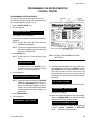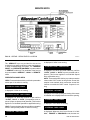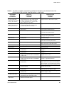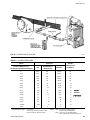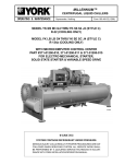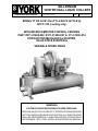
1
MILLENNIUM
CENTRIFUGAL LIQUID CHILLERS
OPERATING & MAINTENANCE
Supersedes: Nothing
1096
FORM 160.48-O1
MODEL YT G0 A1 B1 thru YT L6 D8 F2 (STYLE H)
HCFC-123 (cooling only)
WITH MICROCOMPUTER CONTROL CENTERS
PART #371-01200-002, #371-01200-007 & 371-01200-014
FOR ELECTRO-MECHANICAL STARTER,
SOLID STATE STARTER &
VARIABLE SPEED DRIVE
26874A
WARNING
SYSTEM CONTAINS REFRIGERANT UNDER PRESSURE.
SERIOUS INJURY COULD RESULT IF PROPER PROCEDURES ARE
NOT FOLLOWED WHEN SERVICING SYSTEM. ALL SERVICE WORK
SHALL BE PERFORMED BY A QUALIFIED SERVICE TECHNICIAN IN
ACCORDANCE WITH YORK INSTALLATION/OPERATION MANUAL.
TABLE OF CONTENTS
Section 1: Description of System and Operational Fundamentals .......................... 4
Section 2: MicroComputer Control Center ................................................................. 6
Introduction ................................................................................................... 6
Control Center .............................................................................................. 7
Operation ...................................................................................................... 8
Programming the MicroComputer Control Center ...................................... 13
Service Keys .............................................................................................. 18
Operating Modes ........................................................................................ 20
Compressor Switch .................................................................................... 21
Display Messages ...................................................................................... 21
Section 3: System Operating Procedures ................................................................ 28
Section 4: System Components Description - Compressor/Motor Assembly ...... 35
Section 5: Operational Maintenance ......................................................................... 39
Use of Pump Assisted Turboguard Purge Unit ........................................... 39
Oil Return System ...................................................................................... 42
Charging the Unit With Oil .......................................................................... 44
Section 6: Trouble Shooting ...................................................................................... 46
Section 7: Maintenance .............................................................................................. 52
Renewal Parts ............................................................................................ 52
Checking System for Leaks ....................................................................... 52
Evacuation and Dehydration of Unit ........................................................... 52
Refrigerant Charging .................................................................................. 55
Checking the Refrigerant Charge During Unit Shut Down .......................... 55
Handling Refrigerant for Dismantling and Repairs ..................................... 55
Megging the Motor ...................................................................................... 56
Condensers and Coolers ............................................................................ 56
Compressor ................................................................................................ 59
Electrical Controls ...................................................................................... 59
Section 8: Preventive Maintenance ........................................................................... 59
NOTE: This instruction covers operation of chillers equipped with Electro-Mechanical or Solid State
Starters. If chiller is equipped with Variable Speed Drive, Form 160.00-O1 is to be used in
conjunction with this manual.
REFERENCE LITERATURE
DESCRIPTION
INSTALLATION
OPERATION – VARIABLE SPEED DRIVE
RENEWAL PARTS – UNIT
RENEWAL PARTS – CONTROL PANEL
RENEWAL PARTS – B & C COMPRESSOR
RENEWAL PARTS – E COMPRESSORS
RENEWAL PARTS – F COMPRESSORS
RENEWAL PARTS – C3 COMPRESSORS
WIRING (WITH EM STARTER)
WIRING (WITH SOLID STATE STARTER)
WIRING (WITH VARIABLE SPEED DRIVE)
2
FORM NO
160.48-N1
160.00-O1
160.48-RP5
160.48-RP3
160.45-RP2.2
160.48-RP1
160.48-RP2
160.48-RP4
160.48-PA19
160.48-PA20
160.48-PA21
YORK INTERNATIONAL
FORM 160.48-O1
26874A
FIG. 1 - YT CHILLER WITH ELECTRO-MECHANICAL STARTER
28009A
FIG. 2 - YT CHILLER WITH VARIABLE SPEED DRIVE
YORK INTERNATIONAL
3
SECTION 1
DESCRIPTION OF SYSTEM AND OPERATIONAL
FUNDAMENTALS
SYSTEM OPERATION DESCRIPTION
YORK Millenium chillers are commonly applied to large
air conditioning systems, but may be used on other applications. The unit consists of an open motor mounted
to a compressor (with integral speed increasing gears)
condenser with purge unit, sub-cooler, cooler and flow
control chamber.
The chiller is controlled by a modern state of the art
MicroComputer Control Center which monitors its
operation. The control center is programmed by the
operator to suit job specifications. Automatic timed startups and shutdowns are also programmed to suit
nighttime, weekends, and holidays. The operating status, temperatures, pressures, and other information
pertinent to operation of the chiller are automatically
displayed and read on a 40 character alphanumeric
message display. Other displays can be observed by
pressing the keys as labeled on the control center.
The chiller with the MicroComputer Control Center is
applied with an Electro-Mechanical Starter, a factory
packaged YORK Solid State Starter or a factory packaged Variable Speed Drive that produces even greater
efficiency and energy savings.
ing through the condenser tubes absorbs heat from
the refrigerant vapor, causing it to condense. The condenser water is supplied to the chiller from an external
source, usually a cooling tower. The condensed refrigerant drains from the condenser into the flow control
chamber, where the flow restrictor meters the flow
of liquid refrigerant to the cooler to complete the
refrigerant circuit.
The major components of a chiller are selected to
handle the refrigerant which would be evaporated at
full load design conditions. However, most systems
will be called upon to deliver full load capacity for only
a relatively small part of the time the unit is in operation.
CAPACITY CONTROL
The major components of a chiller are selected for full
load capacities; therefore, capacity must be controlled
to maintain a constant chilled liquid temperature leaving the cooler. Prerotation vanes (PRV), located at the
entrance to the compressor impeller, compensate for
variation in load. (See Fig. 3 Detail A)
In operation, a liquid (water or brine) to be chilled flows
through the cooler, where refrigerant, boiling at low pressure and temperature, absorbs heat from the water. The
chilled liquid is then piped to fan coil units or other air
conditioning terminal units, where it flows through finned
coils, absorbing heat from the air. The warmed liquid is
then returned to the chiller to complete the chilled liquid
circuit.
The position of these vanes is automatically controlled
through a lever arm attached to an electric motor located outside the compressor housing. The automatic
adjustment of the vane position in effect provides the
performance of many different compressors to match
various load conditions from full load with vanes wide
open to minimum load with vanes completely closed.
The refrigerant vapor, which is produced by the boiling
action in the cooler, flows to the compressor where the
rotating impeller increases its pressure and temperature and discharges it into the condenser. Water flow-
For Variable Speed Drive units, the capacity is controlled
by speed modulation as well as prerotation vane control. The Variable Speed Drive selects the combination
of compressor motor speed and prerotation vane opening for the most efficient operation. (See Form 160.00-O1)
4
YORK INTERNATIONAL
FORM 160.48-O1
7619A(D)
FIG. 3 (DETAIL A) - COMPRESSOR PREROTATION VANES
COMPRESSOR
DISCHARGE
SUCTION
DISCHARGE
BAFFLE
COOLER
CONDENSER
ELIMINATOR
SUB-COOLER
FLOW
CONTROL
CHAMBER
FLOW CONTROL
OIL COOLER
LD00478A
FIG. 3 - REFRIGERANT FLOW THROUGH CHILLER
YORK INTERNATIONAL
5
28050A
FIG. 4 - MICROCOMPUTER CONTROL CENTER AND KEYPAD
LD00457
Section 2
MICROCOMPUTER CONTROL CENTER
NOTE: This instruction covers operation of chillers equipped with Electro-Mechanical or Solid State Starters. If
chiller is equipped with Variable Speed Drive, Form 160.00-O1 is to be used in conjunction with this
manual.
INTRODUCTION
The YORK MicroComputer Control Center is a microprocessor based control system for centrifugal chillers. It controls the leaving chilled water temperature
via prerotation vane control and has the ability to
limit motor current via control of the prerotation
vanes. Fur ther, it is compatible with YORK Solid
State Starter, Electro-Mechanical Starter and Variable Speed Drive applications.
A keypad mounted on the front of the Control Center
(see Fig. 4) allows the operator to display system operating parameters on a 40 character alphanumeric display
that is part of the keypad. These readings are displayed
via “Display” keypad as follows: In the English mode;
temperatures in °F, pressures in (PSIA); in the metric
mode, temperatures in °C, pressures in (KPa).
6
• CHILLED LIQUID TEMPERATURES - LEAVING AND
RETURN
• REFRIGERANT PRESSURES - EVAPORATOR AND
CONDENSER
• DIFFERENTIAL OIL PRESSURE
• CONDENSER LIQUID TEMPERATURES - OPTIONAL
FIELD INSTALLED - LEAVING AND RETURN
• OPTIONS
• PRINT
• HISTORY PRINT
• MOTOR CURRENT IN % OF FULL LOAD AMPS
• SATURATION TEMPERATURES - EVAPORATOR
AND CONDENSER
• DISCHARGE TEMPERATURE
• OIL TEMPERATURE
• PURGE PRESSURE
• SOLID STATE STARTER MOTOR CURRENT/ VOLTS
YORK INTERNATIONAL
FORM 160.48-O1
The system setpoints (see Fig. 4) are operator entered
on the front control center “Setpoints” keypad. These
set points can also be displayed on the 40 character
alphanumeric display. The system setpoints are:
•
•
•
•
•
CHILLED LIQUID TEMPERATURE (LCWT)
% CURRENT LIMIT
PULLDOWN DEMAND LIMIT
CLOCK (TIME-OF-DAY)
DAILY SCHEDULE (7 DAY TIME-CLOCK
PROGRAMMING)
• HOLIDAY
• REMOTE RESET TEMPERATURE RANGE
• DATA LOGGER
The cause of all system shutdowns (safety or cycling)
is preserved (until the system is reset or restarts) in the
microcomputer’s memory for subsequent viewing on the
keypad display. The operator is continually advised of
system operating conditions by various background and
warning messages. The keypad contains special service
keys for use by the service technician when performing
system troubleshooting.
The MicroComputer Control Center is designed to be
compatible with most energy management systems
(EMS) in use today. The standard design allows for the
following EMS interface:
1. Remote Start
2. Remote Stop
3. Remote LCWT Setpoint (Pulse Width Modulated
signal)
4. Remote Current Limit Setpoint (Pulse Width Modulated signal)
5. A “Remote Mode Ready to Start” Status Contacts
6. Safety Shutdown Status Contacts
7. Cycling Shutdown Status Contacts
As an enhancement to the standard EMS features, an
optional card file with plug-in printed circuit boards is
available. These optional cards will accept a remote
LCWT 0° to 10°F or 0° to 20°F setpoint offset and/or
remote current limit setpoint interface from three user
input choices:
1. 4-20 mA
2. 0-10 VDC
3. contact closures
CONTROL CENTER
The Control Center front panel layout consists of five
key groups, one switch, and a 1 line by 40 character
alphanumeric vacuum fluorescent display: (See Fig. 4)
functions that are only relevant to servicing the chiller.
Typically, these keys would not be used for daily chiller
operation.
CHARACTER DISPLAY - The alphanumeric vacuum
fluorescent display is located to the right of the “STATUS” key. All messages, parameters, set points, and data
can be viewed at this location. The main communications between the operator or service technician and the
MicroComputer Control Center occurs on this display.
ACCESS CODE - Permits operator to access the program.
DISPLAY - Provide a direct read-out of each monitored
parameter on the alphanumeric display.
ENTRY - These keys are used to enter the values for
the operator programmed setpoints. These keys are
used in conjunction with the “SETPOINT” keys while in
program mode.
SETPOINTS - These keys are used as follows:
1. To view each setpoint, in any Mode, or
2. To select the individual setpoints that are programmed
by the operator in “Program” Mode only.
Pressing the appropriate key enables the operator to
program that setpoint pressing the “ENTRY” keys.
SERVICE - Included in this group of keys are those
YORK INTERNATIONAL
PROGRAM - Permits operator to program the Control
Center.
MODE - Permits operator to check what mode the Control Center is presently in (“LOCAL”, “REMOTE” or “SERVICE”).
1. Service - allows manual PRV control with visual display readout of PRV operation.
2. Local - allows manual compressor start from the
“COMPRESSOR” switch on control center front.
3. Program - allows operator programming of system
setpoints.
4. Remote - allows remote start, remote stop of compressor and remote reset of LCWT and % current
limit.
COMPRESSOR - “START”, “RUN”, “STOP/RESET”
SWITCH - This 3 position rocker switch is used to start
(except in “REMOTE” mode), stop/run/reset the system.
7
OPERATION
DISPLAYING SYSTEM PARAMETERS
The “Display” keys are used to display selected monitored parameters as follows: (Refer to Fig. 4)
• Press and release the appropriate “DISPLAY” key the message will be displayed for 2 seconds.
- or• Press and hold the appropriate “DISPLAY” key - the
message will be displayed and updated every 0.5
seconds until the “DISPLAY” key is released.
- or • Press and release appropriate “DISPLAY” key, then
press and release the “DISPLAY HOLD” key - the
message will be displayed and updated every 2
seconds until the “DISPLAY HOLD” key is again
pressed and released, or 10 minutes have elapsed,
whichever comes first.
NOTE: If the display actually displays X’s, then the monitored parameter is out of normal operating range
(Ref. Fig. 5). If the “English/Metric” jumper is installed on the Micro Board, all temperatures are
displayed in degrees Fahrenheit (°F) and all
pressures are displayed in pounds per square
inch absolute (PSIA), except oil pressure which
is displayed in pounds per square inch differential (PSID). If the “English/Metric’’ jumper is not
installed, all temperatures are displayed in degrees Centigrade (°C) and all pressures are displayed in Kilo-Pascals (KPa).
VARIABLE
DISPLAY -> X’S WHEN
EPROM VERSion
CONDENSER PRESSURE
= < 9.3 PSIA; > 41.6 PSIA
= < 10.0 PSIA; > 40.0 PSIA
(3.B) (3.C)
(Later Versions)
EVAPORATOR PRESSURE
= < 5.0 PSIA; > 12.9 PSIA
= < 4.0 PSIA; > 12.5 PSIA
(3.B) (3.C)
(Later Versions)
= < 9.0 PSIA; > 78.2 PSIA
= < 14.7 PSIA OR > 75.0 PSIA
(Low Pressure Purge Unit)
(3.B) (3.C) (3.E)
(Later Versions)
PURGE PRESSURE
= < 00.0 PSIA or > 100.0 PSIA 031-01097-001
(High Pressure Pump
Through -012 Rev.
Assisted Purge Unit)
.10 and higher
DISCHARGE TEMPERATURE
= < 20.3°F; > 226.4°F
OIL TEMPERATURE
= < 20.3°F; > 226.4°F
LEAVING COND. WATER TEMP.
= < 8.4°F; > 114.4°F
ENTERING COND. WATER TEMP.
= < 8.4°F; = > 114.4°F
LEAVING EVAP. WATER TEMP.
= < 0°F; = > 81.1°F
ENTERING EVAP. WATER TEMP.
= < 0.1°F; > 93.0°F
To Display CHILLED LIQUID TEMPERATURES:
Press “CHILLED LIQUID TEMPS” display key as
described above to produce the following alphanumeric
display message:
CHILLED LEAVING = XXX.X °F, RETURN = XXX.X °F
To Display REFRIGERANT PRESSURE:
Use “REFRIGERANT PRESSURE” display key as described above to produce the following alphanumeric
display message:
EVAP = XXXX.X PSIG, COND = XXXX.X PSIG
To Display OIL PRESSURE:
Use “OIL PRESSURE” display key as described above
to produce the following alphanumeric display message:
OIL PRESSURE = XXXX.X PSID
To Display OPTIONS:
Use the “OPTIONS” key to display and program the optional parameters for “Guardian Service” and “Remote
Chiller Communications”. Refer to instruction Form
160.46-NOM 4.1 for operation and programming. If this
option is not installed,
NO OPTIONS INSTALLED
is displayed when this key is pressed.
To Display SSS MOTOR CURRENT/VOLTS: (Solid
State Starter Applications Only)
If chiller is equipped with a YORK Solid State Starter,
use “SSS MOTOR CURRENT/VOLTS” key to display 3phase compressor motor current and 3-phase solid state
starter input line voltage. Continuously pressing this key
will display the motor current and line voltage alternately.
When used with the “DISPLAY HOLD” key, motor current and line voltage will alternately be displayed
each time this key is pressed. The messages are as follows:
FIG. 5 - SYSTEM PARAMETERS - OUT OF RANGE
READINGS
8
YORK INTERNATIONAL
FORM 160.48-O1
A AMPS = XXXX; B AMPS = XXXX; C AMPS = XXXX
V A – B = XXXX; V B – C = XXXX; V C – A = XXXX
If chiller is not equipped with Solid State Starter, this
key produces the following message:
SOLID STATE STARTER NOT INSTALLED
In program mode, this key is used to display the applicable line voltage range (200-208 VAC, 220-240 VAC,
380 VAC, 400 VAC, 415 VAC, 440-480 VAC, 500-600
VAC, Supply Voltage Range Disabled). The correct line
voltage range is programmed at the YORK factory and
is checked by the service technician at start-up. For
security reasons, a special access code is required to
program the line voltage range. The line voltage range
is used to determine a low line voltage threshold for
cycling shutdown. Refer to “System Setpoints” below
for Trip/Reset values.
To Display CONDENSER LIQUID TEMPERATURES:
(Field Installed Option Package)
Use “CONDENSER LIQUID TEMPS” display key as
described above to produce the following alphanumeric
display message:
COND LEAVING = XXX.X °F. RETURN = XXX.X °F
NOTE: If the condenser liquid thermistors are not
connected, the display will blank when this key
is pressed.
To initiate a PRINT to Printer:
Press the “PRINT” key to initiate a printout to an optional printer. When the key is pressed,
PRINT ENABLE
is displayed. Refer to “MicroComputer Control Center System Status Printers” instruction (Form 160.48NO1.2) for details of the optional printers.
To Display MOTOR CURRENT:
Press the “% MOTOR CURRENT” display key as
described above to display motor current as a percent
of Full Load Amps (FLA). The message is as follows:
MOTOR CURRENT = XXX % FLA
NOTE: For Solid State Starter Applications - the
% Motor Current displayed is the highest of three
line currents divided by the programmed chiller
YORK INTERNATIONAL
FLA value x 100%.
For Electro-Mechanical Starter Applications
- the % of Motor Current displayed is the highest of the three line currents converted to analog voltage calibrated to be 9.7 VDC @ 100%
FLA.
To Display OPERATING HOURS:
Use the “OPERATING HOURS” key as described on
page 8 to produce the following message:
ACCUMULATED RUN TIME = XXXXX HRS.
Version 3.E and later EPROM versions provide OPERATING HOURS and STARTS COUNTER:
OPER. HOURS = XXXXX; START COUNTER = XXXXX
SYSTEM SETPOINTS
The system setpoints may be programmed by the system operator. The “Setpoints” keys are located on the
Control Center keypad. To program, see “Programming
System Setpoints” on page 13. The following is a description of these setpoints (with the English/Metric
jumper installed on the Micro Board):
CHILLED LIQUID TEMP - This key displays the leaving chilled water temperature (LCWT) setpoint in degrees Fahrenheit. If not programmed, the default value
is 45°F. See “Programming System Setpoints”, page 13.
NOTE: If an Energy Management System is interfaced
to the Control Center for the purpose of remote
LCWT setpoint reset, then the operatorprogrammed chilled liquid temp will be the base
or lowest setpoint available to the Energy Management System (EMS). This chilled liquid
temp value must also be entered into the EMS.
Further, any subsequent change to this value
must also be entered into the EMS.
% CURRENT LIMIT - This key displays the maximum
value of motor current permitted by its programmed
setting. The value is in terms of percent of Full Load
Amps (FLA). If not programmed, the default value is
100%. See “Programming System Setpoints”, page 13.
If chiller is equipped with a YORK Solid State Starter,
the system FLA is also displayed. This value is programmed by the factory and should never be changed.
The Micro Board uses this value to calculate and display the % Motor Current parameter that is displayed
when the “% MOTOR CURRENT” display key is pressed.
Also, proper current limit control depends on the correctly programmed FLA value. For security reasons, a
special access code is required to program the FLA value.
It should only be changed by a service technician.
9
PULL DOWN DEMAND - This function is used to provide energy savings following the chiller start-up. This
key displays a programmable motor current limit and
programmable period of time. Operation is as follows:
Whenever the system starts, the Pull Down Demand
Limit is maintained for the programmed time, then the
current limit control returns to % Current Limit setpoint.
The maximum permitted motor current is in terms of %
FLA. The duration of time that the current is limited is in
terms of minutes (to a maximum of 255). If not programmed, the default value is 100% FLA for 00 minutes
(See “Programming System Setpoints”, page 13). Thus,
no pull down demand limit is imposed following system
start, and the % Current Limit setpoint is used.
CLOCK - This key displays the day of the week, time of
day and calendar date. If not programmed, the default
value is
SUNDAY 12:00 AM 1/1/89
(See “Programming System Setpoints”, page 13.)
DAILY SCHEDULE - This key displays the programmed
daily start and stop times, from Sunday through Saturday plus Holiday. If desired, the Control Center can be
programmed to automatically start and stop the chiller
as desired. This schedule will repeat on a 7-day calendar basis. If the Daily Schedule is not programmed, the
default value is 00:00 AM start and stop times tor all
days of the week and the holiday. (Note that the system
will not automatically start and stop on a daily basis with
these default values because 00:00 is an “Impossible”
time for the Micro Board; see “Programming System
Setpoints”, page 13). Finally, one or more days in the
week can be designated as a holiday (See description
under “HOLIDAY” setpoint) and the Control Center can
be programmed (using “DAILY SCHEDULE” setpoint)
to automatically start and stop the chiller on those days
so designated. The operator can override the time clock
at any time using the “COMPRESSOR” switch.
Note that if only a start time is entered for a particular
day, the compressor will not automatically stop until a
scheduled stop time is encountered on a subsequent
day.
HOLIDAY - This key indicates which days in the upcoming week are holidays. On those designated days, the
chiller will automatically start and stop via the holiday
start and stop times programmed in the “DAILY SCHEDULE” setpoint. It will do this one time only and the following week will revert to the normal daily schedule for that
day.
REMOTE/RESETTEMP RANGE - This key displays the
maximum offset of remote LCWT setpoint reset. This
offset is either 10° or 20°F as programmed. When in
the remote mode, this value is added to the operator
programmed chilled liquid temp setpoint and the sum
equals the temperature range in which the LCWT can
10
be reset. For example, if the operator programmed chilled
liquid temp setpoint is programmed with a value of 10°F,
then the chilled liquid temp setpoint can be remotely reset over a range of 46°F to 56°F (46 + 10 = 56). If not
programmed, the default value for this parameter is 20°F.
For additional information on remote LCWT reset, refer
to Form 160.46-PA4.1.
NOTE: If an Energy Management System is interfaced
to the Control Center for the purpose of remote
LCWT setpoint reset, then the operator programmed REMOTE RESET TEMP RANGE
value determines the maximum value of temperature reset controlled by the Energy Management System.
DATA LOGGER - This key is used when an optional
printer is connected to the MicroComputer Control Center. Refer to Form 160.48-NO1.2 for operation instructions.
SSS MOTOR CURRENT/VOLTS - This key is used on
Solid State Starter applications only. Although this is a
display key, it is also used to program the applicable AC
power line voltage range (200-208 VAC, 220-240 VAC,
380 VAC, 400 VAC, 415 VAC, 440-480 VAC, 550-600
VAC). The MicroComputer Control Center uses this entry
to determine the undervoltage-shutdown threshold. For
each line voltage category, there are two shutdown
thresholds - a minimum line voltage level required to
start the compressor and a minimum level required after the Control Center is in “RUN” mode. In “ RUN” mode,
the voltage must be less than the run threshold for 20
continuous seconds in order to initiate a shutdown. When
the chiller shuts down,
MON 10:00 AM LOW LINE VOLTAGE
is displayed. This undervoltage protection can be disabled. The selectable supply voltage ranges and their
shutdown thresholds are as follows:
supply voltage range
TO START
RUN
200-208 VAC
200-240
380
400
415
440-480
550-600
Supply voltage range disabled
174 VAC
200
331
349
362
400
502
0
160 VAC
185
305
320
335
370
460
None
If Control Center is equipped with version 3.E and later
EPROM, an overvoltage shutdown threshold is also
checked. If the line voltage exceeds the overvoltage
threshold for 20 continuous seconds, the chiller shuts
down,
YORK INTERNATIONAL
FORM 160.48-O1
MON XX:XX AM HIGH LINE VOLTAGE
is displayed. The high line voltage check is disabled along
with the low line voltage check if desired. Refer to the
following chart for thresholds.
For security reasons, a special access code is required
to program the supply voltage range. The supply voltage range is programmed at the factory and should only
be changed by a service technician.
press and release the “DISPLAY HOLD” key. The message will be displayed until the “DISPLAY HOLD” key
is again pressed and released, or 10 minutes have
elapsed, whichever comes first.
To Display CHILLED LIQUID TEMP Setpoint:
Use the “CHILLED LIQUID TEMP” setpoint key as described on page 8 to produce the following message:
LEAVING SETPOINT = XX.X °F
LOW/HIGH VOLTAGE TRIP/RESET VALUES
compressor motor
supply voltage
range - (V)
200-208
220-240
380
400
415
440-480
550-600
Supply voltage
range disabled
low line voltage
operating point
cutout-(V)
cutin-(V)
(on fall)
(on rise)
high line voltage
operating point
cutout-(V)
cutin-(V)
(on risei)
(on fall)
160
185
305
320
335
370
460
174
200
331
349
362
400
502
227
262
415
436
454
524
655
220
254
402
423
440
508
635
None
0
None
0
PURGE - There is one programmable purge setpoint:
“EXCESS PURGE THRESHOLD”.
The EXCESS PURGE THRESHOLD is the number of
purge exhausts that are allowed to occur in 1 hour of chiller
operating time before an excess purge warning message
is displayed. If the number of purge exhausts exceed this
value, “WARNING - EXCESS PURGE” is displayed on
the keypad display (Refer to description of this message
in “DISPLAY MESSAGES” section of this book). The DISPLAY DATA key is used to program this setpoint. It is programmable from 10 to 30 purge exhausts per hour by operating personnel. The default value is 20 purge exhausts per hour. Field service personnel can program this
setpoint over a wider range (Refer to service manual Form
160.48-M2, Section 13). The typical value would be the
default value 20/hour. However, the number can be lowered to detect small leaks.
NOTE: The value displayed is the actual LCWT setpoint.
For example, the value displayed in “LOCAL” or
“PROGRAM” modes is that which is operator
programmed. The value displayed in the “REMOTE” mode is that base setpoint with added
temperature reset by an Energy Management
System, via remote LCWT setpoint (PWM signal) if a remote reset signal was received within
30 minutes.
To Display % CURRENT LIMIT Setpoint:
Use “% CURRENT LIMIT” setpoint key as described on
page 8 to produce the following message:
CURRENT LIMIT = XXX ° FLA
NOTE: The value displayed is the actual % current limit
setpoint. For example; the value displayed in
“LOCAL” or “PROGRAM” mode is that which is
operator programmed. The value displayed in
the “REMOTE” mode is that which has been programmed by the Energy Management System
via the remote current limit setpoint input.
If chiller is equipped with a YORK Solid State Starter,
the message is:
CURRENT LIMIT = XXX % FLA; *MTR CUR = 000 FLA
NOTE: On Solid State Starter applications, this value is
programmed at the YORK factory. A special access code is required.
DISPLAYING SYSTEM SETPOINTS
The currently programmed setpoint values can be
viewed at any time (see page 20) in “SERVICE”,
“LOCAL” or “REMOTE” operating mode as follows:
• Press and release the appropriate “Setpoint” key - the
message will be displayed for 2 seconds.
- or • Press and hold the appropriate “Setpoint” key - the
message will be displayed as long as the key is
pressed.
- or -
To Display PULL DOWN DEMAND Setpoint:
Use “PULL DOWN DEMAND” setpoint key as described
on page 8 to produce the following message:
SETPOINT = XX MIN @ XX% LOAD, XX MIN LEFT
To Display CLOCK Setpoint (Time of Day):
Use “CLOCK” setpoint key as described on page 10 to
• Press and release appropriate “Setpoint” key, then
YORK INTERNATIONAL
11
produce the following message:
To Display REMOTE RESET TEMP RANGE Setpoint:
TODAY IS DAY XX:XX AM/PM 1/1/89
To Display DAILY SCHEDULE Setpoints:
Use “REMOTE RESET TEMP RANGE” setpoint key as
described above to produce the following message:
REMOTE RESETTEMP RANGE = 10 °F
- or -
• Press and hold the “DAILY SCHEDULE” setpoint key.
The chiller start and stop times for each day of the
week are sequentially displayed, beginning with
Sunday and ending with Holiday. The display will
continuously scroll until the “DAILY SCHEDULE” key
is released.
-or• Press and release the “DAILY SCHEDULE” setpoint
key. Then press and release the “DISPLAY HOLD” key.
The chiller start and stop times for each day of the
week are sequentially displayed beginning with Sunday and ending with Holiday. The display will continuously scroll until the “DISPLAY HOLD” key is again
pressed and released, or 10 minutes have elapsed,
which ever comes first.
The display message for DAILY SCHEDULE will scroll
in the following sequence:
REMOTE RESETTEMP RANGE = 20 °F
To Display DATA LOGGER Setpoints:
Refer to YORK Form 160.48-NO1.2 for operation of this
key.
To Display UNDERVOLTAGE Setpoints:
(Solid State Starter Applications Only)
Press “SSS MOTOR CURRENT/VOLTS” key in “PROGRAM” mode to display the selected voltage range. One
of the following messages will be displayed:
SUPPLYVOLTAGE RANGE 200 – 208
- or -
SUN START = 08:30 AM STOP = 06:00 PM
SUPPLYVOLTAGE RANGE 220 – 240
MON START = 05:00 AM STOP = 07:00 PM
SUPPLY VOLTAGE RANGE 380
- or -
TUE START = 05:00 AM STOP = 07:00 PM
SUPPLY VOLTAGE RANGE 400
- or -
WED START = 05:00 AM STOP = 07:00 PM
SUPPLY VOLTAGE RANGE 415
- or -
THU START = 05:00 AM STOP = 07:00 PM
SUPPLYVOLTAGE RANGE 440 – 480
- or -
FRI START = 05:00 AM STOP = 07:00 PM
SUPPLYVOLTAGE RANGE 550 – 600
- or -
SAT START = 05:00 AM STOP = 01:00 PM
SUPPLY VOLTAGE RANGE DISABLED
HOL START = 00:00 AM STOP = 00:00 PM
To Display HOLIDAY Setpoints:
Use “HOLIDAY” setpoint key as described in the beginning of this section to produce the following message:
S__ M__ T__ W__ T__ F__ S__ HOLIDAY NOTED BY *
NOTE: On the days that are designated by an *, the
chiller will automatically start and stop per the
holiday schedule established in “DAILY SCHEDULE” setpoints.
12
- or -
A special access code is required to program the Supmonply
startVoltage
= 05:00Range.
am stopThe
= 07:00
pm Voltage Range is proSupply
grammed at the factory and checked at system startup. (Note to service technician: Refer to programming
instructions in Service Instruction 160.48-M2).
To Display PURGE Setpoint:
Press “DISPLAY DATA” key in “PROGRAM” mode to
display the excess purge threshold. The following is
displayed:
MAXIMUM PURGES PER HOUR = XX
YORK INTERNATIONAL
FORM 160.48-O1
PROGRAMMING THE MICROCOMPUTER
CONTROL CENTER
PROGRAMMING SYSTEM SETPOINTS
The system setpoints can be entered at any time . . .
even when the system is running. Proceed as follows to
enter system setpoints. (Refer to Fig. 6)
1. Press “ACCESS CODE” key.
2. This is displayed:
ENTER VALID ACCESS CODE ___ ___ ___ ___
3. Using “Entry” keys, enter 9 6 7 5.
4. As each digit is entered, the characters Y O R K are
displayed.
NOTE: If digits other than 9 6 7 5 are entered,
Y O R K is still displayed.
NOTE: For ease in remembering the code, note that
the letters Y O R K correspond to the digits
9 6 7 5 on a telephone dial.
LD00457
5. Press “ENTER” key.
NOTE: If digits other 9 6 7 5 were entered in step
No. 4,
FIG. 6 - KEYPAD - PROGRAMMING SYSTEM
SETPOINTS
INVALID ACCESS CODE
is displayed when the “ENTER” key is
pressed. If this occurs, enter the correct
access code (9675) and proceed.
6. This is displayed:
ACCESS TO PROGRAM KEY AUTHORIZED
NOTE: Unless terminated by pressing the “ACCESS
CODE” key again, the operator will have access to the “PROGRAM” key for 10 minutes.
When 10 minutes have elapsed, access to
program key will be automatically disabled
and the operator must return to step No. 1 to
gain access.
7. Press “PROGRAM” key.
8. This is displayed:
9. Enter setpoints as detailed below. If you make a mistake when entering a value, press “CANCEL” key and
then “ENTER” key. The display will revert to the default values and the cursor will return to the first
changeable digit. You can then proceed to enter the
correct values. If the entered value exceeds acceptable limits,
OUT OF RANGE – TRY AGAIN!
message will be displayed for 2 seconds, then the
PROGRAM MODE. SELECT SETPOINT
message will reappear.
10. When all the desired setpoints have been entered,
press the “ACCESS CODE” key to exit program mode
and terminate access to program mode.
PROGRAM MODE, SELECT SETPOINT
ACCESS TO PROGRAM MODE DISABLED
is displayed. The Control Center will automatically
return to “LOCAL”, “REMOTE” or “SERVICE”
mode . . . whichever was last selected.
YORK INTERNATIONAL
13
To enter CHILLED LIQUID TEMP Setpoint:
(Refer to Fig. 7)
1. Press and release “CHILLED LIQUIDTEMP” setpoint
key. The following program prompt message will be
displayed:
LEAVING SETPOINT = XX.X °F (BASE)
(BASE) refers to the base or lowest setpoint available to an Energy Management System. If any Energy Management System is applied, this value must
be entered into the Energy Management System.
Refer to previous explanation or REMOTE/RESET
TEMP RANGE, page 10.
2. Use “ENTRY” keys to enter desired value.
3. Press and release “ENTER” key. This message is
displayed:
PROGRAM MODE, SELECT SETPOINT
LD0457
FIG. 7 - KEYPAD - PROGRAMMING “LEAVING
CHILLED WATER TEMP” SETPOINT
To Enter % CURRENT LIMIT Setpoint:
(Electro-Mechanical Starter or VSD)
(Refer to Fig. 8)
1. Press and release “% CURRENT LIMIT” setpoint key.
The following program prompt message is displayed:
CURRENT LIMIT = XXX % FLA
2. Use “ENTRY” keys to enter desired value.
3. Press and release “ENTER” key. This message is
displayed:
PROGRAM MODE, SELECT SETPOINT
(Solid State Starter)
(Refer to Fig. 8)
LD0457
1. Press and release “% CURRENT LIMIT” setpoint key.
The following message is displayed:
CURRENT LIMIT = XXX % FLA
MTR CUR = _ _ _ FLA
FIG. 8 - KEYPAD - PROGRAMMING “% CURRENT
LIMIT” SETPOINT
2. Use “ENTRY” keys to enter desired current limit value.
NOTE: Motor Current FLA value is entered by YORK
factory and checked at system start-up. It cannot be changed without special access code.
(Note to service technician: refer to Programming Instructions in Service Instruction Form
160.48-M2.)
14
3. Press and release “ENTER” key. The following message is displayed:
PROGRAM MODE, SELECT SETPOINT
YORK INTERNATIONAL
FORM 160.48-O1
To Enter PULL DOWN DEMAND Setpoint:
(Refer to Fig. 9)
1. Press and release “PULL DOWN DEMAND”
setpoint key. The following program prompt
message is displayed:
SETPOINT = XXX MIN @ XXX % FLA, XX MIN LEFT
2. Use “Entry” keys to enter desired values. For explanation, see PULL DOWN DEMAND, page 10. Note
that ‘XX min left’ is not an operator entered value.
3. Press and release “ENTER” key. This message is
displayed:
LD0457
PROGRAM MODE, SELECT SETPOINT
FIG. 9 - KEYPAD - PROGRAMMING “PULL DOWN
DEMAND” SETPOINT
To Enter CLOCK Setpoint:
(Refer to Fig. 10)
1. Assure Micro Board Program jumper J-57 is in
“CLKON” position.
2. Press and release “CLOCK” setpoint key. The following program prompt message is displayed:
CURRENT LIMIT = XXX % FLA
3. Press “ADVANCE DAY|SCROLL” key until the proper day of week appears on the display.
4. Use “Entry” keys to enter proper time of day.
5. Press “AM/PM” key to change the AM to PM or vice
versa.
6. Use “Entry” keys to enter proper calendar date.
(MONTH/DAY/YR). If month and day are single digit
entries, precede the entry with “0”. For example 02/
04/88.
LD0457
7. Press and release “ENTER” key. This message is
displayed:
PROGRAM MODE, SELECT SETPOINT
YORK INTERNATIONAL
FIG. 10 - KEYPAD - PROGRAMMING “CLOCK”
SETPOINT
15
To Enter DAILY SCHEDULE Setpoint:
(Refer to Fig. 11)
1. Press and release “DAILY SCHEDULE” setpoint key.
The following program prompt message is displayed:
Press “ADVANCE DAY/SCROLL” key. The display
will advance to the next consecutive day and the
previous day will be automatically entered.
DAY START XX:XX AM/PM STOP XX:XX AM/PM
2. Press “ADVANCE DAY/SCROLL” key until the day
you wish to program appears on the display.
3. Use “Entry” keys to enter desired start time. If you
wish to cancel the scheduled start and stop times
for a particular day, press “CANCEL” key and then
“ENTER” key.
4. Press “AM/PM” key to change the AM to PM or vice
versa. If the desired entry is already displayed, proceed to enter the stop time. The cursor will automatically move to the stop time.
5. Use “Entry” keys to enter desired stop time.
6. Press “AM/PM” key to change the AM to PM or vice
versa.
7. Press and release “ENTER” key. This message is
displayed:
PROGRAM MODE, SELECT SETPOINT
- or -
LD00457
FIG. 11 - KEYPAD - PROGRAMMING “DAILY
SCHEDULE” SETPOINT
To Enter HOLIDAY Setpoint: (Refer to Fig. 12)
1. Press and release “HOLIDAY” setpoint key. The following program prompt message is displayed:
S__ M__ T__ W__ T__ F__ S__ HOLIDAY NOTED BY *
2. Press and release “ADVANCE DAY/SCROLL” key to
move cursor to the day that you wish to designate as
a holiday.
3. Press and release “*” entry key. An * will appear next
to the selected day.
4. After you have placed an * next to each of the days
that you wish to designate a holiday, press “ENTER”
key. The following message is displayed:
PROGRAM MODE, SELECT SETPOINT
To cancel all of the designated holidays: perform Step
1, press “CANCEL” key, and then press “ENTER” key.
This message is displayed:
LD00457
PROGRAM MODE, SELECT SETPOINT
To cancel one of the designated holidays: perform
Step 1, press “ADVANCE DAY/SCROLL” key until
the cursor appears to the right of the desired day,
press the “*” key, then press the “ENTER” key.
16
FIG. 12 - KEYPAD - PROGRAMMING “HOLIDAY”
SETPOINT
YORK INTERNATIONAL
FORM 160.48-O1
To Enter REMOTE/RESET TEMP RANGE Setpoint:
(Refer to Fig. 13)
1. Press and release “REMOTE/RESET TEMP
RANGE” setpoint key. The following program prompt
message is displayed:
REMOTE/RESET TEMP RANGE = XX °F
2. Use “Entry” keys to enter desired value (10 or 20).
3. Press and release “ENTER” key. The following message is displayed.
PROGRAM MODE, SELECT SETPOINT
LD00457
FIG. 13 - KEYPAD - PROGRAMMING “REMOTE
RESET TEMP RANGE” SETPOINT
To Enter DATA LOGGER Setpoint:
Refer to Form 160.48-NO1.2 for operation of this key.
To Enter EXCESS PURGE THRESHOLD Setpoint:
(Refer to Fig. 14)
1. Press and release “DISPLAY DATA” key. The following program prompt message is displayed:
MAXIMUM PURGES PER HOUR = XX
2. Use “ENTRY” keys to enter desired values.
3. Press and release “ENTER” key. The following message is displayed:
PROGRAM MODE, SELECT SETPOINT
LD00457
FIG. 14 - KEYPAD - PROGRAMMING “EXCESS
PURGE THRESHOLD” SETPOINT
YORK INTERNATIONAL
17
SERVICE KEYS
FIG. 15 - KEYPAD - SERVICE KEYS LOCATION
The “SERVICE” keys are provided for the service
technician’s use when performing routine maintenance
or when troubleshooting the system. The “WARNING
RESET” and “PREROTATIONVANES” keys are enabled
in “SERVICE” mode only. The remainder of the Service
keys are enabled in “SERVICE”, “LOCAL” or “REMOTE”
mode.
PREROTATION VANES KEYS
OPEN - Press and release this key to drive the prerotation
vanes open. If the chiller is running,
SYSTEM RUN - VANES OPENING
is displayed. If chiller is not running,
SYS READY TO START – VANES OPENING
is displayed. The vanes will continue to open until the
“CLOSE”, “HOLD”, or “AUTO” (if temperature error requires it) keys are pressed and released. (This function
applies to non-Variable Speed Drive applications only.)
HOLD - Press and release this key to hold the prerotation
vanes in their present position. If chiller is running,
SYSTEM RUN – VANES HOLDING
18
LD00457
is displayed. If chiller is not running,
SYS READY TO START – VANES HOLDING
is displayed. The vanes will remain stationary until the
“OPEN”, “HOLD” or “AUTO” keys are pressed and released. (This function applies to non-Variable Speed
Drive applications only.)
AUTO - Press and release this key to put the prerotation
vanes under LCWT control as long as the current limit
setpoint is not reached, which causes the current limit
function to override the LCWT control. If system is running,
SYSTEM RUN – AUTO VANES
is displayed.The actual opening and closing of the vanes
is indicated on the display. When the vanes are opening,
SYSTEM RUN – VANES OPENING
is displayed. If the vanes are closing,
SYSTEM RUN – VANES CLOSING
is displayed. Whenever the Control Center is in “LOCAL”, “REMOTE” or “PROGRAM” mode, the vane conYORK INTERNATIONAL
FORM 160.48-O1
trol circuitry is automatically placed in “AUTO” mode and
the vanes operate to control the leaving chilled water
temperature to the programmed setpoint. (This function
applies to non-Variable Speed Drive applications only.)
CLOSE - Press and release this key to drive the
prerotation vanes closed. If the chiller is running,
SYSTEM RUN –VANES CLOSING
is displayed. If chiller is not running,
No. 3
PURGE PRESSURE = XX.X PSIA
No. 4 (See Note below)
60 MINUTE PURGE COUNT BYPASS; XX MIN LEFT
Purge exhausts are not counted during the first 60 minutes of chiller operation. Therefore, this message replaces the purge count messages below during the first
hour of operation.
SYS READYTO START – VANES CLOSING
is displayed. When the vanes are fully closed,
SYS READYTO START – VANES CLOSED
is displayed. The vanes will continue to close until the
“OPEN”, “HOLD” or “AUTO” keys are pressed. (This function applies to non-Variable Speed Drive applications
only.)
OTHER SERVICE KEYS
WARNING RESET - Press and release this key to reset
the excess purge counting circuitry and the excess purge
display message. Also, any “WARNING” or “STATUS”
message can be reset with this key, unless the condition still exists. To reset any cycling or warning message, place the Control Center in “SERVICE” mode and
press “WARNING RESET” key. To reset any safety shutdown message, press “WARNING RESET” key in “SERVICE” mode with the “COMPRESSOR” switch in the
“STOP/RESET” position.
MANUAL OIL PUMP - This key is operational in any
mode. Press and release this key to run the oil pump.
Press and release the key again to stop the oil pump. A
10-minute maximum is imposed on the running of the
oil pump (i.e., the oil pump will automatically shut off
after 10 minutes). If a longer running time is desired,
the key must be pressed again.
DISPLAY DATA - This key is operational in any three of
the Control Center modes of operation (“SERVICE”, “LOCAL” or “REMOTE”). It is used to display certain system operating parameters that are relevant to troubleshooting the chiller system.
Press and hold the “DISPLAY DATA” key. The following
messages will sequentially scroll on the display. Each
message will be displayed for 2 seconds.
No. 1
SAT TEMPS EVAP = XX.X °F, COND = XX.X °F
No. 2
DISCHARGE TEMP = XXX.X °F, OILTEMP = XXX.X °F
YORK INTERNATIONAL
PURGES LAST XX MIN = XX, MAX PURGES/HR = XX
After the first hour of chiller operation has elapsed, purge
exhausts are counted. This message is displayed during the first hour following the initial 1 hour bypass (see
above), and after the excess purge message is cleared.
The minutes elapsed during this first hour of purge exhaust counting are displayed. The purge count is
incremented each time a purge exhaust occurs. Also,
the excess purge threshold that has been programmed
by the operator or service person is displayed as MAX
PURGES/HR. When the minute count reaches 60, this
message is replaced with the following message:
PURGES LAST HOUR = XX; MAX PURGES/HR = XX
After the initial 1 hour bypass and the first hour of purge
exhaust counting has elapsed as explained above (2
hours of chiller run time), this message is displayed
thereafter. A running total of the number of purge exhausts
that have occurred within the last hour is displayed. The
excess purge threshold that has been programmed by
the operator or service person is displayed as MAX
PURGES/HR.
To hold each of the above messages, press and release
the “DISPLAY DATA” key, then press and release the
“DISPLAY HOLD” key. Message No. 1 above will be displayed and updated every 2 seconds until the “DISPLAY
DATA” key is again pressed and released. Message No.
2 is then displayed and updated every 2 seconds until
the “DISPLAY DATA” key is again pressed and released.
Message No. 3 is then displayed and updated every 2
seconds until either the “DISPLAY DATA” key is again
pressed and released (whereupon message No. 1 is
displayed), or the “DISPLAY HOLD” key is pressed and
released (whereupon the “DISPLAY DATA” messages
are removed from the display.)
NOTE: Purge Count - following a 1 hour bypass at start,
purge exhausts are counted and displayed in
the above messages while the chiller is running.
With the exception of the first hour after the bypass, the value displayed is the number of exhausts that have occurred in the “Last Hour”.
For example, if you walk up to the Micro Panel
at 9:11 AM and press the “DISPLAY DATA” key
19
and it says that there have been 7 purges in the
“Last Hour”, that means that there have been 7
exhausts since 8:11 AM. If you do this at 2:57
PM, it means that there have been 7 exhausts
since 1:57 PM, etc.
The purge count is reset to zero by:
A. Clearing the excess purge message.
B. Moving the Micro Board program jumper
J-57 (CLK ON/OFF) from “CLK OFF” to
CLOCK ON” position.
C. Starting the chiller.
The purge count is frozen by the following:
A. When the chiller is not running.
B. An excess purge message is being displayed and at least 1 full hour of purge
exhausts have accumulated.
HISTORY PRINT - This key is used to initiate a history
print to the optional printer. Refer to Form 160.48-NO1.2
for operation of this key.
OPERATING MODES
The MicroComputer Control Center can be operated in
four different operating modes as follows:
SERVICE - Enables all the Service keys except “DISPLAY DATA”, “MANUAL OIL PUMP”, and “HISTORY
PRINT”, which are enabled in all modes. See “Service
Keys”, page 18.
LOCAL - This is the normal operating mode. The compressor can be started and stopped from the Control
Center. Also, the Display and Setpoints parameters can
be displayed.
PROGRAM - Allows the operator to program the
Setpoints parameters, and change operating modes.
REMOTE - In this mode, the Control Center will accept
control signals form a remote device (i.e., Energy Management System) or cycling inputs. The control signal
inputs are:
1. Remote Start
2. Remote Stop
3. Remote LCWT Setpoint
4. Remote Current Limit Setpoint
NOTE: The compressor can be stopped by the “COMPRESSOR” switch, regardless of the operating
mode. The switch must be in “RUN” position to
enable “REMOTE” mode. The operator cannot
locally start the compressor using the “COMPRESSOR” switch when in the “REMOTE”
mode.
To determine which operating mode the Control Center
is presently in, simply press the “MODE” key.
• If the Control Center is in “LOCAL” mode, this is
displayed:
LOCAL OPERATING MODE IN EFFECT
20
• If the Control Center is in “REMOTE” mode, this is
displayed:
REMOTE OPERATING MODE IN EFFECT
• If the Control Center is in “SERVICE” mode, this is
displayed:
SERVICE OPERATING MODE IN EFFECT
To change operating mode, proceed as follows:
1. Press “ACCESS CODE” key.
2. This message appears:
ENTER VALID ACCESS CODE __ __ __ __
3. Using “Entry” keys, enter 9 6 7 5.
4. As each digit is entered, the characters Y O R K are
displayed.
NOTE: If digits other than 9 6 7 5 are entered,
Y O R K is still displayed.
5. Press “ENTER” key.
NOTE: If digits other than 9 6 7 5 were entered in step
No. 4,
INVALID ACCESS CODE
is displayed when the “ENTER” key is pressed.
If this occurs, enter the correct access code
(9 6 7 5) and proceed.
6. This message is displayed:
ACCESS TO PROGRAM KEY AUTHORIZED
NOTE: Unless terminated by pressing the “ACCESS
CODE” key again, the operator will have access to the “PROGRAM” key for 10 minutes.
YORK INTERNATIONAL
FORM 160.48-O1
When 10 minutes have elapsed, access to
“PROGRAM” key will be automatically disabled and the operator must return to step
No. 1 to gain access.
11. Press “ADVANCE DAY” key to scroll to desired
mode. Each time this key is pressed, a different
mode is displayed as above:
7. Press “PROGRAM” key.
12. When the desired mode is displayed, press “ENTER” key.
8. This message is displayed:
13. This message is displayed:
PROGRAM MODE, SELECT SETPOINT
PROGRAM MODE, SELECT SETPOINT
9. Press “MODE” key.
10. The mode that has been previously selected will be
displayed as follows:
LOCAL MODE SELECTED
SERVICE MODE SELECTED
- or -
14. Press “ACCESS CODE key to exit “PROGRAM”
mode and terminate access to “PROGRAM” mode.
15. This message is displayed:
ACCESS TO PROGRAM MODE DISABLED
- or -
REMOTE MODE SELECTED
COMPRESSOR SWITCH
(Refer to Fig. 15, page 18)
This rocker switch is used to locally operate the compressor. It is used to start, run and stop the compressor.
Also, it resets the Control Center after a safety shutdown.
To START* chiller compressor in “LOCAL” mode:
Move “COMPRESSOR” switch from “STOP/RESET”
to “START” position. Switch will spring-return to “RUN”
position.
To STOP compressor:
Move switch from “RUN” to “STOP/RESET” position.
To RESET Control Center:
Following a safety shutdown, the operator is required
to reset the Control Center prior to restarting the
system. Move switch from “RUN” to “STOP/RESET”
position.
*NOTE: The operator cannot start the compressor
(using this switch) when the Control Center
is in “REMOTE” mode.
DISPLAY MESSAGES
The following display messages will be automatically
displayed unless the operator is requesting additional
information via the keypad.
SYSTEM RUN – CURRENT LIMIT IN EFFECT
Displayed when the chiller is running, and the motor
current is equal to or greater than the operatorprogrammed “XXX % FLA” current limit value. When
the motor current reaches 100% of this value, the
prerotation vanes are not permitted to open further. If
the current continues to rise to 104% of this value, the
vanes will be driven closed - not fully closed; only far
YORK INTERNATIONAL
enough to allow the current to decrease to a value less
than 104% of the operator-programmed “XXX % FLA”
current limit.
For example:
With the operator-programmed “% CURRENT LIMIT”
set at 50% and the FLA of the chiller equal to 200A,
the current limit circuit would perform as follows:
(100%) (50% x FLA) = Vanes inhibited from opening further
(104%) (50% x FLA) = Vanes driven toward close
position
21
Therefore:
(100%) (50% x 200) = 100A = Vanes stop opening
(104%) (50% x 200) = 104A = Vanes driven toward
close position
SYSTEM RUN – AUTO VANES
Displayed when the chiller is running, the MicroComputer
Control Center is in “SERVICE” mode, and the vanes
are operating in “AUTO” mode.
SYSTEM RUN – VANES OPENING
Displayed when the chiller is running and the MicroComputer Control Center is in “SERVICE” mode with:
• The vanes operating in “AUTO” mode and opening to
maintain the leaving chilled water temperature
setpoint.
-or• The operator has pressed the vanes “OPEN” key on
the keypad.
SYSTEM RUN – VANES CLOSING
Displayed when the chiller is running and the MicroComputer Control Center is in “SERVICE” mode with:
• The vanes operating in “AUTO” mode and closing to
maintain the leaving chilled water temperature
setpoint.
-or• The operator has pressed the vanes “CLOSE” key on
the keypad.
SYSTEM RUN – VANES HOLDING
Displayed when the chiller is running, the MicroComputer Control Center is in “SERVICE” mode, and
the operator has pressed the vanes “HOLD” key.
SYS READY TO START – VANES OPENING
Displayed when the chiller is not running and the operator has pressed the vanes “OPEN” key on the keypad.
SYS READY TO START – VANES CLOSING
Displayed when the chiller is not running and the operator has pressed the vanes “CLOSE” key on the keypad.
SYS READY TO START – VANES HOLDING
Displayed when the chiller is not running and the operator has pressed the vanes “HOLD” key on the keypad.
22
SYSTEM RUN – LOW PRESSURE LIMIT IN EFFECT
Displayed when the chiller is running and the evaporator pressure falls to 5.55 PSIA (R11); 4.50 PSIA (R123).
Simultaneously, the prerotation vanes will be prevented
from further opening. This action maintains chiller operation to prevent low-evaporator-pressure shutdown at 5.42
PSIA (R11); 4.40 PSIA (R123). When the evaporator
pressure rises to 5.65 PSIA (R11); 4.70 PSIA (R123),
the vanes will be permitted to open. Low pressure limit
feature is not used when program jumper (JP-3) is cut
(Brine application).
SYSTEM RUN – HIGH PRESSURE LIMIT IN EFFECT
Displayed when the chiller is running and the condenser
pressure rises to 28.8 PSIA. Simultaneously, the prerotation vanes will be inhibited from further opening. This
action occurs to prevent system shutdown on high condenser pressure at 29.7 PSIA. When the condenser
pressure falls to 28.6 PSIA, the vanes will be permitted
to open.
SYSTEM RUN – PRESS STATUS
Displayed when the chiller is running. It instructs the
operator to press the “STATUS” key, whereupon the following message will be displayed. The following “Warning Messages” are displayed alternately with the foreground message. The foreground message is displayed
for 2 seconds, then the warning message is displayed
for 2 seconds, etc. It is not necessary to press the “STATUS” key.
WARNING: COND OR EVAP TRANSDUCER ERROR
Indicates a probable condenser or evaporator transducer
problem, because the output is unreasonable. The microprocessor arrives at this conclulsion by subtracting
the evaporator transducer output from the condenser
transducer output. The result must be zero or some positive number. If the result is a negative number, it concludes that there is a probable condenser or evaporator
transducer problem. This function is inhibited for the first
10 minutes of chiller run-time, and is checked every 10
minutes thereafter. Message is reset by pressing the
“WARNING RESET” key in the “SERVICE” mode.
WARNING: PURGE FLOAT SWITCH ERROR
Indicates the microprocessor is receiving conflicting digital signals from purge top float switch and purge bottom
float switch (i.e., liquid is simultaneously above TFS and
below BFS . . . an impossible condition). Message is
reset by pressing “WARNING RESET” key in the “Service” mode.
YORK INTERNATIONAL
FORM 160.48-O1
WARNING: HIGH PURGE PRESSURE
If the purge transducer output is indicating a pressure
greater than 95 PSIA (for 255 continuous sec.) the above
warning message is displayed alternately with the normal foreground message. When the pressure decreases
to less than 95 PSIA, the message is automatically
cleared.
MON XX:XX WARNING – EXCESS PURGE
Anytime after the first hour of chiller operation, if the
purge exhaust count equals the programmed “MAX
PURGE/HR” threshold, this message is alternately displayed with the normal foreground message. The day
and time displayed is the time the excess purge event
occurred. This message will be displayed until manually
cleared using the “WARNING RESET” key in the “Service” mode. Clearing the message also resets the purge
exhaust count to zero and invokes the message
PURGES.LAST XX MIN = XX; MAX PURGES/HR = XX
While the excess purge message is displayed, the purge
exhaust count will continue to increment until the 1 hour
period has elapsed. The count is then frozen until the
excess purge message is cleared. This provides a record
of the total number of purge exhausts that occurred
within the 1 hour period that the excess purge event
occurred.
Refer to “DISPLAY DATA” key in SERVICE KEYS section for complete explanation of purge counting.
NOTE: If the “STATUS” key is arbitrarily pressed, without the operator being prompted by the
PRESS STATUS
message, this message shall be displayed:
NO MALFUNCTION DETECTED
SYSTEM RUN – LEAVING TEMP CONTROL
Displayed while the chiller is running. Indicates that the
prerotation vanes are being controlled by the leaving
chilled water temperature (LCWT). This is the normal
mode of chiller operation. Thus, if the LCWT is above
the setpoint, but pulling down rapidly, the vanes will pulse
closed as the LCWT nears the setpoint.
SYSTEM READY TO START
Indicates that the system is not running, but will start
upon application of a start signal.
YORK INTERNATIONAL
SYSTEM SHUTDOWN – PRESS STATUS
Displayed when chiller is shut down on a cycling shutdown, safety shutdown (operator must move the “COMPRESSOR” switch to “STOP/RESET” in order to restart)
or operator-initiated shutdown (within 30 minutes of initial start-up). The status message consists of the day
and time of shutdown, cause of shutdown, and type of
restart required. Upon pressing “STATUS” key, “System
Shutdown Message” will be displayed for 2 seconds and
then return to
SYSTEM SHUTDOWN – PRESS STATUS
Display can be held indefinitely by depressing “DISPLAY
HOLD” key. For examples of “System Shutdown Messages”, see below.
SYSTEM SHUTDOWN MESSAGES
Day of Week Time of Day
Cause of Shutdown
Type of Restart
MON 10:00 AM – LOW WATER TEMP – AUTOSTART
Chiller was shut down Monday at l0:00AM because the
LCWT has decreased to a value that is 4°F below the
operator-programmed chilled liquid temperature
setpoint. However, if the setpoint is less than 40°F, the
chiller will 20 always shut down at 36°F. Further, if the
chiller is running and the setpoint is changed, the (Low
Water Temperature) cutout will be 36°F for l0 minutes in
order to eliminate nuisance trips. Finally, for brine chilling applications, the LWT cutout is always 4°F below
the setpoint (The water jumper on the Micro Board must
be removed for a brine unit).
MON XX:XX AM – LOW WATER TEMP – VSD – AUTOSTART
Variable Speed Drive has shut down the chiller because
the LCWT has decreased to a value that is 4°F below
the operator-programmed chilled liquid temperature
setpoint. If the chiller is running and the setpoint is increased greater than 4°F, the Variable Speed Drive will
initiate a shutdown. The shutdown is caused by LWT
contact supplied from the Variable Speed Drive.To cause
the Micro Board to monitor the Variable Speed Drive
LWT input, the non-Variable Speed Drive jumper on the
Micro Board must be removed.
MON XX:XX AM – FLOW SWITCH – AUTOSTART
Chiller is shut down because a chilled-liquid flow switch
has opened. The flow switch must open for a minimum
of 2 seconds in order to cause a shutdown. The flow
switch is checked 25 seconds into “Start Sequence Initiated” and continuously thereafter.
23
MON XX:XX AM – SYSTEM CYCLING – AUTOSTART
A remote command (computer relay contact or manual
switch) connected to the Remote/Local cycling input of
the digital input board has shut down the chiller.
MON XX:XX AM – MULTI UNIT CYCLING – AUTOSTART
Lead/Lag sequence control accessory has shut down
the chiller.
MON XX:XX AM – POWER FAILURE – AUTOSTART
The chiller is shut down because there has been a power
interruption or failure. The chiller will automatically
restart when power is restored. This message will be
displayed if the Micro Board is configured for “AUTO RESTART AFTER POWER FAILURE”. The Micro Board is
factory set for manual restart after power failure. To convert it to auto restart after power failure, remove one of
the two-pin program jumpers from the cloth bag located inside the Control Center and place it on the
terminals labeled “Auto R” (J-60) on the Micro Board.
SYSTEM RUN – LEAVING TEMP CONTROL
If equipped with 3.E or later EPROM. This check is not
performed when Micro Board program jumper JP-4 is
removed (Steam Turbine applications).
MON XX:XX AM – INTERNAL CLOCK – AUTOSTART
The operator-programmed daily stop schedule has shut
down the chiller. The chiller will automatically restart
when the operator-programmed daily star t schedule
initates a start. It can be overridden by pressing the
“COMPRESSOR” switch to the “START” position.
REMOTE STOP
This message will be displayed when a remote device
(typically an Energy Management System) has commanded the chiller to shut down. The chiller will restart
upon application of a separate start signal from the remote device. This message will only be displayed when
Control Center is in “REMOTE” mode.
ANTI-RECYCLE, XX MIN LEFT
MON XX:XX AM – POWER FAILURE
The chiller is shut down because there has been a power
interruption or failure. When power is restored, the chiller
can be restarted by pressing the “COMPRESSOR”
switch to “STOP/RESET” position and then to “START”
position. This message will be displayed if the Micro
Board is configured for “MANUAL RESTART AFTER
POWER FAILURE”. The Micro Board is factory set for
manual restart after power failure. This has been accomplished by removing the two-pin jumper from the
terminals fabled “Auto R” (J-60) on the Micro Board.
AC UNDERVOLTAGE – AUTOSTART
The chiller is shut down because the MicroComputer
Control Center was in “RUN” mode, displaying
SYSTEM RUN – LEAVING TEMP CONTROL
but the motor current was less than 10% FLA for 25 continuous seconds. This is indicative of an AC undervoltage
condition that has caused the start relay (1R) in the
MicroComputer Control Center to de-energize. This condition is checked when the MicroComputer Control Center goes into “RUN” mode (after 30 second pre-lube). This
condition can also be caused by failure of any component
that would cause a loss of the start signal from the Control Center. In essence, this check assures that the compressor is running when the Control Center is displaying
24
The chiller may not restart more frequently than every
30 minutes. Displayed when chiller is shut down and
there is time remaining on the anti-recycle timer. In normal operation, chiller cannot be restarted until
ANTI-RECYCLE, 00 MIN LEFT
is displayed. However, when servicing the chiller, it may
be desirable to inhibit this 30-minute timer. If so, simply
install a jumper plug in the unmarked terminals of the
Micro Board directly under Auto Restart jack.
WARNING
Remove this jumper after servicing. Failure to do
this voids the Warranty.
MON XX:XX AM – LOW EVAP PRESSURE
The chiller is shut down because the evaporator pressure
has decreased to 5.42 PSIA (R11); 4.40 PSIA (R123).
The chiller will be allowed to start when the pressure increased to 5.43 PSIA (R11); 4.41 PSIA (R123). To restart
chiller, press the “COMPRESSOR” switch to the “STOP/
START” position and then to the “START” position.
MON XX:XX AM – LOW EVAP PRESSURE – BRINE
The chiller is shut down because the brine Low Evapo-
YORK INTERNATIONAL
FORM 160.48-O1
rator Pressure (LEP, not included with standard Control
Center) safety contacts have opened. The brine LEP
safety is located external to the Control Center. Safety
cutout settings will vary with the brine application. To
restart the chiller, wait until the safety contacts close,
press the “COMPRESSOR” switch to the “STOP/RESET”
position and then to the “START” position.
MON XX:XX AM – LOW OIL PRESSURE
The chiller is shut down because the oil pressure has
decreased to 15 PSID while running, or never achieved
20 PSID prior to compressor start during the oil pump
pre-lube run. The chiller will be allowed to restart when
the pressure increases to 20 PSID. Differential pressure
is sensed by two pressure transducers. To restart chiller,
press “COMPRESSOR” switch to “STOP/RESET” position and then to the “START” position.
MON XX:XX AM – HIGH PRESSURE
The chiller is shut down because condenser pressure
has increased to 15 PSIG (29.7 PSIA). System will be
allowed to restart when pressure decreases to 9 PSIG
(23.7 PSIA). Pressure is sensed by a High Pressure
(HP) safety control that is located on a mounting bracket
above the oil-pump starter located on the condenser
near the purge unit. This message is prompted by the
opening of the HP safety control contacts. To restart
chiller, press “COMPRESSOR” switch to the “STOP/
RESET” position and then to the “START” position.
MON XX:XX AM – EVAP TRANS OR PROBE ERROR
The chiller is shut down because the leaving chilled water
temperature minus the evaporator saturation temperature is outside the range of -2.5°F to +25°F continuously for 10 minutes. To restart the chiller, press
“COMPRESSOR” switch to “STOP/START” position and
then to “START” position. On Brine applications (program jumper JP-3 removed), this check is no longer performed when the evaporator transducer is reading a
pressure below its “out-of-range” threshold.
MON XX:XX AM – MOTOR CONTROLLER – EXT. RESET
The chiller is shut down because a current module
(CM-2 Electro-Mechanical starter application), or the
YORK Solid State Starter, or Variable Speed Drive initiated a shutdown. To restart system, reset the external
device that caused the shutdown. The chiller will automatically restart.
NOTE: The following motor controller shutdowns do not
require an external reset to restart the chiller.
1. Variable Speed Drive - over-current, repeat trip, overtemperature.
YORK INTERNATIONAL
2. Solid State Starter - power fault, 110°F start inhibit,
phase rotation/loss, out of lock.
3. Current Module - power fault.
MON XX:XX AM – POWER FAULT – AUTOSTART
The chiller is shut down because of a Solid StateStarter
or current module (CM-2 Electro-Mechanical starter
application) “Power Fault” shutdown. The chiller will automatically restart. This function is sensed by the motor
controller input to the digital input board. A power-fault
shutdown is initiated by the motor controller contacts
(CM-1) opening and reclosing in one second.
MON XX:XX AM HIGH DISCHARGE TEMP
The chiller is shut down because the discharge temperature has increased to 220°F. The system will be allowed to restart when the temperature has decreased
to 219°F. Temperature is sensed by a thermistor RT2.
To restart the chiller, press “COMPRESSOR” switch to
“STOP/RESET” position and then to the “START” position.
MON XX:XX AM HIGH OIL TEMP
The chiller is shut down because the oil temperature
has increased to 180°F. The system will be allowed to
restart when the temperature decreases to 179°F. The
temperature is sensed by a thermistor RT3. To restart
the chiller, press “COMPRESSOR” switch to “STOP/
RESET” position and then to the “START” position.
MON XX:XX AM – OIL PRESSURE TRANSDUCER
Chiller is shut down because to oil pressure has increased to 60 PSID. The chiller will be allowed to restart
when the oil pressure decreases to 59 PSID. Pressure
is sensed by two oil-pressure transducers that are sensing low and high sump pressure. This safety shutdown
is provided primarily as a check on the oil pressure transducers. Display of this message is generally indicative
of a defective transducer or interface. To restart the
chiller, press “COMPRESSOR” switch to “STOP/RESET”
position and then to the “START” position.
VANE MOTOR SWITCH OPEN
Chiller is shut down because a system-start sequence
has been initiated, but the prerotation vanes are not fully
closed.
MON XX:XX AM – STARTER MALFUNCTION DETECTED
The chiller is shut down because the Control Center
has detected a motor-current value greater than 15%
25
FLA for 10 seconds minimum anytime when the compressor-start signal is not energized. To restart the chiller,
press “COMPRESSOR” switch to “STOP/RESET” a position and then to the “START” position.
MON XX:XX AM – PROGRAM INITIATED RESET
The chiller is shut down because the Micro Board did
not receive a hardware-generated interrupt on schedule. Typical is an Analog/Digital Converter interrupt. This
message is indicative of a Micro Board hardware failure
or electrical noise on Micro Board. The chiller will automatically restart. This message indicates that the watchdog timer-circuit has reset the microprocessor. This occurs when the time needed to step through program is
longer than allowable, thus the software program is initialized at the beginning.
SYSTEM READYTO START – PRESS STATUS
The chiller was shut down on a safety shutdown and
will start upon application of a local or remote start signal. Since the message states that the chiller is “Ready
to Start”, it means that the condition that caused the
shutdown no longer exists and the Control Center has
been manually reset. When the “STATUS” key is pressed,
a message is displayed that describes the reason for
shutdown. The message will be displayed for 2 seconds
and then return to
Those messages that could be displayed are any of
the previously described safety-shutdown messages
or warning messages. They can be cleared from the
display by entering “Service” mode and pressing
“WARNING RESET” key. Or, the message will be
cleared by initiating a compressor start.
START SEQUENCE INITIATED
Indicates that the Micro Board has received a local or
remote start signal and has initiated the chiller start-up
routine. This is the compressor pre-lube period. The
duration of this period is controlled by the “Prerun” (JP-6)
wire jumper on the Micro Board as follows:
FUNCTION
Jumper Position
30 SEC. OIL PUMP RERUN
INSTALLED
*180 SEC. OIL PUMP RETURN
CUT
26
Displayed while motor is decelerating atter a chiller
shut down. The oil pump is running during this period.
The duration of this period is controlled by the “CSTDN”
(JP-4) wire jumper on the Micro Board as follows:
FUNCTION
Jumper Position
150 SEC. COASTDOWN
INSTALLED
* 6 MIN. COASTDOWN
CUT
* Use on steam turbine applications only.
MON XX:XX AM – MTR PHASE CURRENT UNBALANCE
(Solid State Starter Applications Only)
The chiller is shut down because the compressormotor current was unbalanced while the chiller was
running. The current balance is only checked atter the
motor has been running for a minimum of 45 seconds
and the motor current is 80% FLA or greater. If the
current in any phase deviates from the average (a+b+c
3 )
current by greater than 30% for a minimum of 45 consecutive seconds, a shutdown is initiated. To restart the
system, press the “COMPRESSOR” switch to “STOP/
RESET” position and then to the “START” position. An
example of the conditions for shutdown is as follows:
If
IøA = 200A
IøB = 200A
IøC = 118A
SYSTEM READY TO START – PRESS STATUS
* Only used on YDTK 131-144 “F” compressors.
SYSTEM COASTDOWN
Then
IAV = 200 + 200 + 118
3
IAV = 173A
IACCEPTABLE = 173 ± 30% = 121A or 225A
Therefore
Since IøC = 118A which is less than the acceptable 121A, the chiller would shut down if this unbalance exists tor 45 consecutive seconds.
MON XX:XX AM – LOW LINEVOLTAGE
(Solid State Starter Applications Only)
Chiller is shut down because the voltage in any phase
of line voltage has decreased below the under-voltageshutdown threshold for 20 consecutive seconds, or failed
to achieve the minimum required starting line-voltage.
Refer to explanation under “System Setpoints - SSS
Motor Current/Volts”, page 8. The system will automatically restart when all phases of line voltage increase to the minimum required starting voltage.
YORK INTERNATIONAL
FORM 160.48-O1
MON XX:XX AM – HIGH LINEVOLTAGE
(Solid State Starter Applications Only)
Chiller is shut down because the voltage in any phase
of line voltage has increased above the over-voltage
threshold for 20 consecutive seconds. Refer to explanation under “System Setpoints - SSS Motor Current/
Volts”, page 8. The system will automatically restart
when all phases of line voltage decrease to the maximum allowable line voltage to start the chiller.
MON 09:30 AM LOW OIL TEMPERATURE – AUTOSTART
Whenever the oil temperature falls below 55°F, or the oil
temperature sensor is disconnected from the Micro
Board, the preceding message will appear. The system
will automatically restart when the display indicates 71°F.
MON XX:XX AM FAULTY DISCHARGETEMP SENSOR
Whenever the discharge temperature falls below 32°F,
or the discharge temperature sensor is disconnected
from the Micro Board, the preceding message will appear. To restart the system when the discharge temperature rises or the sensor has been connected, press
the “COMPRESSOR” switch to the “STOP/RESET” position and then to the “START” position.
MON XX:XX AM – AUX SAFETY SHUTDOWN
The system is shut down because an external device,
connected to digital input board TB1-31 (Aux Safety
Shutdown Input), has initiated a system shutdown. This
input is a general purpose input that can be used to
annunciate a user-defined safety shutdown. To restart
chiller, press “COMPRESSOR” switch to “STOP/RESET”
position and then to the “START” position.
REPLACE RTC, U16 – REPROGRAM SETPOINTS
Indicates that the battery located inside the REAL-TIME
CLOCK IC Chip (U16 on the Micro Board) is defective.
This battery provides back-up power to the RTC memory
(RAM) in the event of a utility AC power failure. This
assures the system setpoints will be maintained. If this
message appears, the RTC IC Chip (U16) on the Micro
Board must be replaced. If there had been a power failure
while this message is displayed, the setpoints will have
been lost and must be reprogrammed. Order a replacement RTC IC Chip (YORK part number 031-00955-000)
from the YORK Parts Distribution Center. With AC power
removed from system, locate RTC Chip U16 on the Micro
Board and remove existing RTC Chip from socket and
discard. Observe anti-static precautions and install new
RTC Chip in socket. Assure proper IC orientation - orientation notch must be UP. (Refer to Fig. 16)
MICRO BOARD
U16 RTC 1C CHIP
REAL-TIME CLOCK
24673A
FIG. 16 - MICROCOMPUTER CONTROL CENTER - INTERIOR - WITH PANEL OPEN - LOCATION OF REAL TIME
CLOCK U16 RTC IC CHIP
YORK INTERNATIONAL
27
SECTION 3
SYSTEM OPERATING PROCEDURES
28050A
FIG. 17 - MICROCOMPUTER CONTROL CENTER AND KEYPAD
LD00457
WARNING
OIL HEATERS
If the oil heater is de-energized during a shutdown period, it must be energized for 12 hours
prior to starting compressor, or remove all oil and
recharge compressor with new oil. (See “Oil
Charging Procedure”, page 44.)
NOTE: The oil heater is thermostatically controlled and remains energized as long as
the fused disconnect switch to the starter
or Variable Speed Drive is energized.
28
CHECKING THE OIL LEVEL
IN THE OIL RESERVOIR
Proper operating oil level - the middle of the upper sight glass.
If the oil is excessively high after start-up, the
excess oil may be drained from the oil filter drain
valve while the compressor is running.
If oil level is low, oil should be added to the compressor. (See “Oil Charging Procedure”, page 44.)
YORK INTERNATIONAL
FORM 160.48-O1
START-UP PROCEDURE
Pre-Starting
Prior to starting the chiller observe the MicroComputer
Control Center. Make sure the display reads
must be programmed for the proper day and time.
Any setpoints which are desired to be changed may
be programmed. If not programmed the “default”
value setpoints are as follows:
LCWT = 45°F
% Current Limit = 100% FLA
Pulldown Demand = None
Clock = Sun 12:00A.M.
Daily Schedule = None
Holiday = None
Remote Reset Temp. Range = 20°F
Data Logger = No Operation
SYSTEM READY TO START
To pre-start the chiller use the following procedure:
1. OIL HEATER - The oil heater must be energized for
12 hours prior to starting the chiller. The unit will not
start if the oil is less than 71°F. If not possible the
compressor oil should be drained and new oil must
be charged into the oil sump. (See “Oil Charging
Procedure”, page 44.)
2. OIL PUMP - To check, press and release the
“MANUAL OIL PUMP” key under “Service” on the
Control Center. The oil pump will run for 10 minutes
and shut down. Press and release the “MANUAL OIL
PUMP” key to stop the operation of the oil pump for
less than 10 minutes of operation.
3. PREROTATION VANES - To perform this test the
starter interlock terminals 3 and 4 must be jumpered
to allow vanes to open (remove the jumper after test).
Make sure the Control Center is in the “SERVICE”
mode, then press the prerotation vanes “OPEN” and
“CLOSE” keys to observe the operation of the
prerotation vanes. The Control Center supplies a signal to operate the prerotation vanes. The movement
of the vanes will be displayed on the control center.
The display readout is active whenever power is supplied to the control center. Return from the “Service”
mode to “Local”, “Program”, or “Remote” mode to
suit the method of operation selected for the chiller
application. On Variable Speed Drive units, the vanes
may be manually controlled by a switch on the capacity board in the logic box. Thus, the keypad vane
control keys are non-functional on Variable Speed
Drive units.
4. % CURRENT LIMIT - Press the “% CURRENT
LIMIT” setpoint key on the Control Center. The display should read
CURRENT LIMIT = 100% FLA
On Solid State Starter units only, the display is
CURRENT LIMIT = 100% FLA, MTR CUR = XXXX FLA
if the Control Center was not programmed. If the setpoint is not 100% and was predetermined for the job
application the Control Center should be programmed to that specification.
5. All Control Center setpoints should be programmed
before the chiller is started. Prior to start, the clock
YORK INTERNATIONAL
Start-Up
1. If the chilled water pump is manually operated, start
the pump. The Control Center will not allow the chiller
to start unless chilled liquid flow is established
through the unit. (A field supplied chilled water flow
switch is required.) If the chilled liquid pump is wired
to the MicroComputer Control Center the pump will
automatically start, therefore, this step is not necessary.
2. To start the chiller, press the “COMPRESSOR
START” switch. This switch will automatically spring
return to the “RUN” position. (If the unit was previously started press the “STOP/RESET” side of the
“COMPRESSOR” switch and then press the “START”
side of the switch to start the chiller.) When the start
switch is energized the Control Center is placed in
an operating mode and any malfunction will be noted
by messages on the 40 character alphanumeric display. (See Fig. 17)
Note:
Any malfunctions which occur during “STOP/
RESET” are also displayed.
When the chiller is shut down, the prerotation vanes
will close automatically to prevent loading the compressor on start-up. When the prerotation vanes are
fully closed the display will read
SYSTEM READY TO START – VANES CLOSED
when in “SERVICE” mode. When the chiller starts to
operate, the following automatic sequences are initiated: (Refer to Fig. 18, “Chiller Starting & Shutdown
Sequence”.)
1. The MicroComputer Control Center alphanumeric
display message will read
START SEQUENCE INITIATED
for the first 30 seconds of the starting sequence. (3
min. if Micro Board JP-6 removed)
2. The compressor vent line solenoid valve will open
after the first 5 minutes of unit operation. The solenoid will close automatically after the compressor
shuts down.
29
FIG. 18 - CHILLER STARTING SEQUENCE & SHUTDOWN SEQUENCE
3. The 1R-1 contacts of the 1R start relay will remain
open for the first 30 seconds of oil pump operation.
These contacts will close, starting the compressor
motor and the condenser water pump at the end of
the 30 second period.
4. The oil pump will start to circulate oil for a 30 second pre-run to establish oil flow and adequate lubrication to all bearings, gears, and rotating surfaces
within the compressor.
The high and low oil pressure transducers (OP) and
the oil temperature sensor (RT3) will sense any malfunction in the lubrication system and activate one
of the following display messages:
DAY 10:30 AM – LOW OIL PRESSURE
LD00465
ter the compressor starts. If the chiller shuts down
during this period of time it cannot be started until
the timer completes the 30 minute cycle.
6. The chilled liquid pump contacts will close, starting
the chilled liquid pump to allow liquid flow through
the cooler when the “COMPRESSOR” start switch is
energized.
7. After the first 30 seconds of operation, the compressor will start and the Control Center display message will read
SYSTEM RUN – CURRENT LIMIT IN EFFECT
while the motor is accelerating to full speed. When
the motor reaches full speed and the current falls
below 100% FLA the message will read
DAY 10:30 AM – HIGH OIL PRESSURE
SYSTEM RUN – LEAVING TEMP. CONTROL
DAY 10:30 AM – LOW OIL TEMP – AUTOSTART
Chiller OPERATION
DAY 11:30 AM – OIL PRESSURE TRANSDUCER
5. The anti-recycle timer software function will operate
after the 30 seconds of pre-run time. At this time the
timer will be initiated and will run for 30 minutes af30
After the compressor reaches its operating speed the
prerotation vanes will begin to open under the control of
the micro processor board or the logic section of the
Variable Speed Drive which senses the leaving chilled
liquid temperature. The unit capacity will vary to mainYORK INTERNATIONAL
FORM 160.48-O1
tain the leaving chilled liquid temperature setpoint. The
prerotation vanes are modulated by an actuator under
the control of the microprocessor board or logic section
of the Variable Speed Drive. The vane control routine
employs proportional plus derivative (rate) control action. A drop in chilled liquid temperature will cause the
actuator to close the prerotation vanes (and also decreases the speed of the motor if equipped with a Variable Speed Drive) to decrease chiller capacity. When
the chilled liquid temperature rises, the actuator will open
the prerotation vanes and increase the compressor
motor speed of the chiller (if controlled by the Variable
Speed Drive), to increase the capacity of the unit.
However, the current draw (amperes) by the compressor motor cannot exceed the setting of the “% CURRENT LIMIT” at any time during the unit operation, since
the MicroComputer Control Center 40 to 100% three
phase peak current limit software function, plus the 3
phase 100% solid state overload current limiter (CM-2)
on Electro-Mechanical Starter applications or the solid
state starter current limit function will override the temperature control function (or the logic section of the
Variable Speed Drive) and prevent the prerotation
vanes from opening beyond the “% CURRENT LIMIT”
setting.
If the load continues to decrease, after the prerotation
vanes are entirely closed, the chiller will be shut down
by the Low Water Temperature control (LWT) function
which is displayed on the Control Center as:
MON 10:30 AM – LOW WATER TEMPERATURE – AUTOSTART
- or -
LD00466
FIG. 19 - MINIMUM ENTERING CONDENSING
WATER TEMPERATURE
chilled water temperature. Cooling tower fan cycling
will normally provide adequate control of the entering
condenser water temperature on most installations.
CHECKING OPERATION
MON 03:50 PM – LOW WATER TEMPERATURE –VSD AUTOSTART
During operation, the following conditions should be
periodically checked:
This occurs when the leaving water temperature falls
to 4°F below setpoint or 36°F, whichever is higher. The
LWT is part of the Micro Board or the capacity control
board (part of the logic section of the Variable Speed
Drive).
1. On starting, the prerotation vanes should remain
closed.
NOTE: If the temperature setpoint has been reprogrammed within the last 10 minutes, the LWT
cutout is 36°F for 10 minutes.
Condenser Water Temperature Control
The YORK Millenium chiller is designed to use less
power by taking advantage of lower than design temperatures that are naturally produced by cooling towers
throughout the operating year. Exact control of condenser water, such as a cooling tower bypass, is not
necessary for most installations. The chiller requires only
that the minimum condenser water temperature be no
lower than the value determined by referring to Fig. 19.
At start-up the entering condenser water temperature
may be as much as 25°F colder than the standby return
YORK INTERNATIONAL
2. Be sure the oil pump is operating while unit is running.
3. Check Oil Pressure display. A gradual decrease in
bearing oil pressure of 5 to 10 PSI (with constant
suction and discharge pressures) may be an indication of a dirty filter. The filter should be replaced when
pressure loss is 30% or more of the original pressure. The actual bearing oil pressure will vary with
compressor suction and discharge pressures. When
a new system is first operated under normal full load
conditions, the bearing oil pressure should be recorded as a reference point with which to compare
subsequent readings.
OPERATING LOG SHEET
A permanent daily record of system operating conditions (temperatures and pressures) recorded at regular
intervals throughout each 24 hour operating period
should be kept.
31
LD00467
23889A
*NOTE: These items can be printed by an electronic printer connected to J-11 of the Micro Board and pressing the
PRINT key on the Micro Board or automatically using the Data Logger feature.
FIG. 20 - LIQUID CHILLER LOG SHEETS - FORM 160.44-F6
An optional status printer is available for this purpose
or Fig. 20 shows a log sheet used by YORK personnel
for recording test data on chillers. It is available from
the factory in pads of 50 sheets each under Form No.
160.44-F6 and may be obtained through the nearest
YORK office. Automatic data logging is possible by connecting the optional printer and programming the DATA
LOGGER function; Ref. Form 146.48-NO1.2.
An accurate record of readings serves as a valuable
reference for operating the system. Readings taken when
a system is newly installed will establish normal conditions with which to compare later readings.
For example, dirty condenser tubes may be indicated
by higher than normal temperature differences between
leaving condenser water and refrigerant leaving the
condenser.
OPERATING INSPECTIONS (See Section 2)
By following a regular inspection using the display
readings of the MicroComputer Control Center, and
maintenance procedure, the operator will avoid serious operating difficulty. The following list of inspections and procedures should be used as a guide.
Daily
1. Check MicroComputer Control Center displays.
32
2. If the compressor is in operation, check the bearing oil pressure by pressing “OIL PRESSURE” key
to read the display on the Control Center. Also check
the oil level in the oil reservoir. Drain or add oil if
necessary.
3. Check entering and leaving condenser water pressure and temperatures for comparison with job design conditions. Condenser water temperatures can
be checked by pressing “CONDENSER LIQUIDTEMPERATURES” display key.
4. Check the entering and leaving chilled liquid temperatures and evaporator pressure for comparison
with job design conditions. This can be accomplished
by pressing the “CHILLED LIQUID TEMPS” key and
the “Refrigerant Pressures” key.
5. Check the condenser saturation temperature (based
upon condenser pressure sensed by the condenser
transducer). Press the “DISPLAY DATA” key. This key
may be depressed repeatedly after depressing the
“Display Hold” key to display three different parameters.
6. Check the compressor discharge temperature.
Press “Display Data” key. During normal operation
discharge temperature should not exceed 220°F.
7. Check the compressor motor voltage and current
YORK INTERNATIONAL
FORM 160.48-O1
(amps) at E-M starter (or Variable Speed Drive), or
on the Control Center display for Solid State Starter
units.
8. Check for any signs of dirty or fouled condenser
tubes. (The temperature difference between water
leaving condenser and liquid refrigerant leaving the
condenser should not exceed the difference recorded
for a new unit by more than 4°F.)
9. Verify proper water treatment.
10. If the chiller is controlled by a YORK Variable Speed
Drive, check the operating lights on the logic section. (Refer to 160.00-O1)
11. Press the “STATUS” key whenever the display indicates so. This allows any warning messages to be
displayed, such as “EXCESS PURGE”, “HIGH
PURGE PRESSURE”, “REPROGRAM SETPOINTS”,
etc.
Weekly
1. Check the refrigerant charge. (See “Checking the
Refrigerant Charge”, page 55)
Quarterly
1. Change the purge unit dehydrator at least quarterly,
or more often if required.
2. Clean purge foul gas strainer.
3. Perform chemical analysis of oil.
4. Clean water strainer on VSD (if equipped).
Semi-Annually (or more often as required.)
1. Change and inspect compressor oil filter element.
facturer’s instructions.
b. Meg motor windings - See Fig. 30 for details.
c. Relubricate ball bearings.
CAUTION: Don’t overlook motor drive end bearing
located in motor support of F1, F2 compressors.
4. Purge unit.
a. Clean and inspect all valves.
b. Drain and flush purge shell.
c. Clean orifices.
5. Inspect and service electrical components as necessary.
6. Perform chemical analysis of system.
Every Two Years
1. If unit is equipped with SSS or VSD, flush cooling
circuit and replace with new coolant solution, York
Part # 013-02987-000.
NEED FOR PURGING THE SYSTEM
To assure satisfactory operation, it is important that these
systems be kept free of moisture laden air and noncondensable gases. Air in the system usually collects in the
condenser, blanketing some of the condensing surface,
causing the discharge pressure and temperature to rise,
resulting in high operating cost, and possibly surging,
or shutdown of system by high pressure cutout. Moisture in the system causes acid formation which is destructive to internal system parts.
A Turboguard purge unit is furnished and mounted at
the rear of the system (See Fig. 21). The purpose of
2. Oil return system
a. Change dehydrator.
b. Check nozzle of eductor for foreign particles.
3. Check controls and safety cutouts.
4. Check level of coolant if equipped with SSS or VSD.
CHECK VALVE
FLOAT SWITCH ASS’Y.
Annually (more often if necessary.)
1. Drain and replace the oil in the compressor oil sump
(See “Oil Charging Procedure”, page 44).
PUMP
2. Cooler and Condenser
a.
b.
c.
d.
Inspect and clean water strainers.
Inspect and clean tubes as required.
Inspect end sheets.
Backflush heat exchanger on VSD (if equipped).
3. Compressor Drive Motor (See motor manufacturer’s
maintenance and service instruction supplied with
unit)
27406A(D)
a. Clean air passages and windings per manuYORK INTERNATIONAL
FIG. 21 - TURBOGUARD PURGE UNIT
33
this unit is to automatically remove the mixture of
noncondensable gases and refrigerant from the top of
the condenser, expel the noncondensables to the atmosphere and return the refrigerant to the system.
IMPORTANT
The purge unit operates continuously when the
system is in operation.
The Turboguard purge unit includes a display message
on the control center display. The message reads
WARNING: EXCESS PURGE
if an excessive air leak is present within the chiller. The
“WARNING RESET” should be pushed with the Control Center in “Service” mode to reset the display. Leak
check and correct the leak if the display continues to
show this message.
NEED FOR MAINTENANCE OR SERVICE
If the system is malfunctioning in any manner or the
unit is stopped by one of the safety controls, consult
Table 2, “Operating Analysis Chart” (pages 50 and 51)
of this instruction manual. After consulting this chart, if
you are unable to make the proper repairs or adjustments to start the compressor or the particular trouble
continues to hinder the performance of the unit, please
call the nearest YORK District Office. Failure to report
constant troubles could damage the unit and increase
the cost of repairs considerably.
NORMAL AND SAFETY SYSTEM SHUTDOWNS
Normal and safety system shutdowns have been built
into the chiller to protect it from damage during certain
operating conditions. Therefore, it should be understood
that at certain pressures and temperatures the system
will be stopped automatically by controls that respond
to high temperatures, low temperatures, and low and
high pressures, etc. Table 1 is an explanation of each
specific shutdown. If the chiller shuts down on a “Safety”
shutdown the display will read
not installed on the Micro Board)
Low Evaporator Pressure
Low Oil Pressure
High Condenser Pressure
Evaporator Transducer or Probe Error
High Discharge Temperature
High Oil Temperature
Oil Pressure Transducer
Starter Malfunction Detected
Faulty Discharge Temperature
Sensor Aux. Safety Shutdown
Motor Phase Current Unbalance (Solid State Starter
Unit only)
• VSD Shutdowns (See Form 160.00-O1)
•
•
•
•
•
•
•
•
•
•
•
If the chiller shuts down on a “Cycling” shutdown the
display will read:
SYSTEM SHUTDOWN – PRESS STATUS
Upon pressing the “status” key the day-of-week, timeof-day and cause of shutdown are displayed. These shutdowns do not require the operator to manually reset the
Control Center prior to restarting the chiller. The chiller
will automatically restart when the cycling condition is
removed.
CYCLING SHUTDOWNS
• Power Failure (If auto restart programming jumper is
installed on the Micro Board)
• Low Water Temperature
• Flow Switch
• System Cycling
• Multi-Unit Cycling
• Internal Clock
• Anti-Recycle
• Motor Controller (manual reset of the CM-2 module
on E-M starter units, the logic board of the SSS or
VSD may be required)
• Power Fault
• Low Oil Temperature
• Program Initiated Reset
• AC Undervoltage
• Low Line Voltage (Solid State Starter Units only)
• VSD Shutdowns (See Form 160.00-O1 )
SYSTEM SHUTDOWN – PRESS STATUS
Upon pressing the “status” key, the day-of-week, timeof-day and cause of shutdown are displayed. Safety shutdowns require the operator to manually reset the Control Center prior to restarting the chiller. When the display reads “Start Sequence Initiated” the cause of the
safety shutdown is automatically cleared from the
memory.
SAFETY SHUTDOWNS
STOPPING THE SYSTEM (See Fig. 4)
The MicroComputer Control Center can be programmed
to start and stop automatically (maximum, once each
day) whenever desired. Refer to Section 2. To stop the
chiller proceed as follows:
1. Push the compressor switch to “STOP/RESET”. The
Control Center display will show
SYSTEM COASTDOWN
• Power Failure (If auto restart programming jumper is
34
YORK INTERNATIONAL
FORM 160.48-O1
for 150 seconds (6 min. if Micro Board jumper JP-4
removed). The compressor, condenser water, and
cooling tower fans will stop automatically. The oil
pump will continue to run for a period of 150 seconds. The oil pump will then stop automatically.
Once stopped, the
SYSTEM COASTDOWN
display will be replaced by
2. If freezing temperatures are encountered while the
system is idle, carefully drain the cooling water from
the cooling tower, condenser, condenser pump, and
the chilled water system-chilled water pump and
coils. Open the drains on the cooler and condenser
liquid heads to assure complete drainage. (If a Variable Speed Drive, drain its water cooling system. If
Solid State Starter, drain water from starter cooling
loop. Isolate theTurboguard purge unit from the main
system.)
3. Isolate the Turboguard purge unit from the main system.
SYSTEM READY TO START
2. Stop the chilled water pump (if not wired into the
Microcomputer Control Center, in which case it will
shut off automatically simultaneously with the oil
pump.) (The actual water pump contact operation is
dependent upon the position of Micro Board jumper
J-54.)
4. Move jumper J-57 on the Micro Board from CLOCK
ON position (CLKON) to CLOCK OFF position
(CLKOFF) while 115VAC control power is applied.
This conserves the battery.
3. Open the switch to the cooling tower fan motors, if
used.
5. Open the main disconnect switches to the compressor motor, condenser water pump and the chilled
water pump. Open the 115 volt circuit to the Control
Center.
4. The compressor sump oil heater (thermostatically
controlled) is energized when the unit is stopped.
START UP AFTER PROLONGED SHUTDOWN
PROLONGED SHUTDOWN
If the chiller is to be shut down for an extended period of
time (for example, over the winter season), the following paragraphs outline the procedure to be followed.
1. After the system pressure has risen above atmospheric, test all system joints for refrigerant leaks
with a leak detector. If equipment room is below 70°F,
circulate hot water (not to exceed 100°F) through
the cooler tubes to raise the system pressure. If any
leaks are found, they should be repaired before allowing the system to stand for a long period of time.
During long idle periods, the tightness of the system
should be checked periodically.
1. When putting the system into operation after prolonged shutdown (during the winter), remove all oil
from the compressor. Install a new filter element and
charge compressor with fresh oil. Replace purge unit
and oil return filters. Move jumper J-57 on the micro
board from CLOCK OFF position (CLKOFF) to
CLOCK ON position (CLKON) and reset the clock.
Energize the 115 volt circuit to the Control Center to
energize the compressor sump oil heater for at least
12 hours.
2. Operate the “Oil Pump” (press and release the
manual oil pump key) until steady oil pressure is established. Then press and release the “Oil Pump”
key to stop operation of the oil pump. If the water
systems were drained fill the condenser water circuit and chilled liquid circuit.
SECTION 4
SYSTEM COMPONENTS DESCRIPTION COMPRESSOR/MOTOR ASSEMBLY
CASING - The casing is accessible with vertical circular joints and fabricated of close-grain cast iron. The
motor assembly is completely removable from the compressor rotor and scroll assembly. Compressor castings are designed for 15 PSIG working pressure and
hydrostatically pressure tested at 50 PSIG.
COMPRESSOR - The rotor assembly consists of a heat
treated alloy steel drive shaft (integral with pinion gear)
and a lightweight, high strength, fully shrouded cast
YORK INTERNATIONAL
aluminum impeller. The impeller is designed for balanced
thrust. The impeller is dynamically balanced to insure
vibration free operation and is overspeed tested for safety.
BEARINGS - Insert type journal and thrust bearings
are fabricated of aluminum alloy and are precision bored
and axially grooved.
INTERNAL GEARS - Single helical gears with crowned
teeth are employed so that more than one tooth is in
contact at all times to provide even distribution of the
35
compressor load with quiet operation. Gears are integrally assembled in the compressor rotor support and are
oil film lubricated. Each gear is individually mounted in
journal bearings with individual thrust bearings to insure
proper balance of forces from the impeller and motor.
LUBRICATION SYSTEM - YORK lubricating oil is force
fed to all bearings and filtered by an externally mounted
15 micron replaceable cartridge oil filter equipped with
service valves. An automatic oil recovery system returns
oil to the compressor that has migrated into the refrigerant system. Heat is removed from the oil by a refrigerant-cooled oil cooler, located in the evaporator. All oil
piping is completely factory-installed and tested. A thermostatically controlled heater is supplied in the oil reservoir to limit the amount of refrigerant absorbed by
the oil when the compressor is not operating.
Oil (under pressure) is supplied from the oil reservoir by
an internally-mounted submersible oil pump. Oil Pump
motors are available in 208 through 600V-3Ph-60/50Hz
to match the application and are supplied complete with
starter and current sensing overloads for extra protection. The oil reservoir heater is 1000 watts, 115V-1Ph60/50Hz immersion type. A separate three phase power
supply is required except when ordered with a YORK
Solid State Starter or Variable Speed Drive. A gravity
flow oil reservoir is provided to feed the bearings and
gears during coast down in the event of a power failure.
CAPACITY REDUCTION - Prerotation vanes (PRV)
modulate the unit capacity from 100% to 10% of design,
on normal air conditioning jobs. The prerotation vanes
are airfoil-shaped and made of manganese bronze. An
external, electric PRV operator automatically controls
the vane position through a simple, reliable linkage.
SHAFT SEAL - The compressor drive shaft seal consists of a spring-loaded, precision lapped carbon ring,
high temperature elastomer “O” ring static seal, and
stress-relieved, precision lapped cast iron collar.The seal
features a small face area and low rubbing speed. It
provides an efficient seal under both vacuum and pressure conditions. The seal is oil-flooded at all times and
is pressure-lubricated during compressor operation.
OPEN MOTOR - The 3600 RPM open motor is a dripproof, squirrel cage, induction type constructed to YORK
design specifications by nationally-known manufacturers. Standard low voltage (208 through 600V-3Ph-60/
50Hz) motors are available for full-voltage (across-theline) or reduced-voltage (solid state, star delta or auto
transformer) starting. Standard high voltage (2300
through 4160V-3Ph60/50Hz) motors are available for fullvoltage (across-the-line) or reduced-voltage (primary reactor or auto transformer) starting. Open close coupled
motors are built with a cast iron adapter flanged between the motor and compressor. This unique design
allows the motor to be coupled to the compressor.
MOTOR TERMINAL BOX - The casing is fabricated of
heavy gauge steel. There are six terminals (three for
36
high voltage) in the terminal box. Provisions are furnished for 208 through 600 volts for three-lead types of
starting (solid state, across-the-line, and auto transformer). Motor terminal lugs are furnished with theYORK
Current Guard Starter and the Variable Speed Drive
mounted in the power section. Overload/overcurrent
transformers (CT’s) are furnished as listed below; in
motor terminal box, as follows:
Application
#CT’s Furnished in Motor Terminal Box
E-M STARTER
3
SS STARTER
0
VS DRIVE
0
COMPRESSOR LUBRICATION SYSTEM
The chiller lubrication system consists of the oil pump,
oil filter, oil cooler and all interconnecting oil piping and
passages. (See Fig. 22) There are seven main points
within the motor-compressor which must be supplied
with forced lubrication as follows:
1. Compressor Drive Shaft (Low Speed)
a. Shaft seal.
b. Front and rear journal bearings - one on each
side of driving gear.
c. Low speed thrust bearing (forward and reverse).
2. Compressor Driven Shaft (High Speed)
a. Forward and reverse high speed thrust bearing.
b. Three journal bearings (YDTJ67 through 95 and
YDTL108 through 126). Two journal bearings
(YDTL131 and 144).
3. Speed Increasing Gears
a. Meshing surfaces of drive and pinion gear teeth.
To provide the required amount of oil under the necessary pressure to properly lubricate these parts, a motor
driven submersible oil pump is located in a remote oil sump.
Upon pressing of the “Compressor Start” switch on the
control center, the oil pump is immediately energized.
After a 30 second delay to allow the system oil pressure
to stabilize, the compressor motor will start. The oil pump
will continue to run during the entire operation of the
compressor, and for 150 seconds during compressor
coastdown.
The submerged oil pump takes suction from the surrounding oil and discharges it to the oil cooler where
heat is rejected. The oil flows from the oil cooler to the
oil filter. The oil leaves the filter and flows to the emergency oil reservoir where it is distributed to the
compressor bearings. The oil lubricates the compressor rotating components and is returned to the oil sump.
Since the emergency oil reservoir is at the highest point
in the lubrication system, it provides an oil supply to
YORK INTERNATIONAL
FORM 160.48-O1
the various bearings and gears in the event of a system shutdown due to power failure. The reservoir, located on the top of the compressor, allows the oil to be
distributed through the passages by gravity flow, thus
providing necessary lubrication during the compressor coastdown.
OIL PUMP
For normal operation the oil pump should operate at all
times during the chiller operation. Manual pump operation may be used to establish stable oil pressure before
starting. When depressed and released, the “Manual
Oil Pump” key will operate the oil pump for 10 minutes
and then automatically shut off. To stop the oil pump
sooner, depress the “Manual Oil Pump” key again.
On shutdown of the system for any reason, the oil pump
operates and continues to run for 150 seconds. The
system cannot restart during that time interval.
OIL HEATER
During long idle periods, the oil in the compressor oil
reservoir tends to absorb as much refrigerant as it can
hold, depending upon the temperature of the oil and the
pressure in the reservoir. As the oil temperature is lowered, the amount of refrigerant absorbed will be
increased. If the quantity of refrigerant in the oil becomes excessive, violent oil foaming will result as the
pressure within the system is lowered on starting. This
foaming is caused by refrigerant boiling out of the oil as
the pressure is lowered. If this foam reaches the oil pump
suction, the bearing oil pressure will fluctuate with possible temporary loss of lubrication, causing the oil pressure safety cutout to actuate and stop the system. See
Section 2.
To maintain the lowest possible concentration of refrigerant in the oil, the compressor oil reservoir is equipped with a 115 volt electric reservoir oil heater. The oil
heater is thermostatically controlled at all times during
compressor shutdown to maintain the sump oil at 135°F
to 145°F. If the oil temperature falls below 55°F, the display will read
SYSTEM SHUTDOWN – PRESS STATUS
Pressing the “STATUS” key causes the message to read
DAY 10:00 AM – LOW OIL TEMP – AUTOSTART
The system will be allowed to automatically restart when
oil temp rises to 71°F.
SHELLS - The cooler and condenser shells are rolled
carbon steel plate with fusion welded seams. A thick
tube sheet is welded to each end of the shell and is
drilled and reamed to accommodate the tubes. All shells
have a design working pressure of 15 PSIG and are
pressure-tested at 30 PSIG.
YORK INTERNATIONAL
TUBES - Individually-replaceable, 3/4" O.D., integralfinned copper heat exchanger tubes are used in the
cooler and condenser. The tubes are roller-expanded
into the tube sheets, providing a leak-proof seal.
COMPACT WATER BOXES - Removable water boxes
are fabricated of steel. The standard design working
pressure is 150 PSIG and the boxes are tested at 225
PSIG. Integral steel water baffles are located and welded
within the water box to provide required 1, 2, or 3-pass
arrangements. Water nozzle connections with Victaulic
grooves are welded to the water boxes. These nozzle
connections are suitable for Victaulic couplings, welding or flanges (300 PSI has flanges). 1/2" coupling and
separable well are located in the entering and leaving
chilled liquid nozzles for temperature sensing elements.
Plugged 1/2" or 3/4" drain and vent connections are provided in each water box.
COOLER - The cooler is a horizontal, flooded, shelland-tube type, with a distribution system consisting of a
distributor trough to give uniform distribution throughout the shell length and a perforated distributor plate,
located under the entire tube bundle, to equally distributor refrigerant. Intermediate steel tube supports are
spaced at intervals of less than four feet. Highly efficient, aluminum mesh eliminators are located above the
tube bundle to prevent liquid refrigerant carryover into
the compressor.
A liquid level sight glass is conveniently located on the
side of the cooler to aid in determining proper refrigerant charge.
CONDENSER - The condenser is a horizontal, shelland-tube type, with a discharge gas baffle to prevent
direct high velocity impingement on the tubes. This baffle
is also used to distribute the refrigerant gas flow properly for most efficient heat transfer. A purge connection
is located in the condenser for efficient elimination of
noncondensibles. Intermediate steel tube supports are
spaced at intervals of less than four feet.
REFRIGERANT FLOW CONTROL - The flow control
chamber is welded to the bottom of the condenser to
allow complete drainage of liquid refrigerant from the
condenser. The chamber contains a single fixed-orifice
flow control with no moving parts.
BURSTING DISC - A 2" or 3" frangible carbon bursting
disc relief device is located in the compressor suction
line.
CONTROL CENTER (See Section 2)
A microprocessor based Control Center is factory
mounted, wired and tested on each chiller. The Control
Center enclosure is a NEMA Type 1 and is provided with
a hinged door with lock and key. The MicroComputer
Control Center automatically controls the operation of
the unit in meeting system cooling requirements while
minimizing energy use.
37
FIG. 22 - SCHEMATIC DRAWING - YT COMPRESSOR LUBRICATION SYSTEM
38
LD00468
YORK INTERNATIONAL
FORM 160.48-O1
SOLID STATE STARTER (OPTIONAL)
The Solid State Starter is a reduced-voltage liquid cooled
starter that controls and maintains a constant current
flow to the motor during start-up. The starter is mounted
on the chiller. The power wiring from the starter to the
motor and from the starter control transformer to the
Control Center is factory wired and tested. Available for
200-600V-3Ph-60/50Hz power; 2 or 3 barrel lug connections per phase are provided on the starter. The starter
enclosure is NEMA Type1 and is provided with a hinged
door with lock and key.
vane position for maximum part load efficiency by analyzing information fed to it by sensors located throughout the chiller.
VARIABLE SPEED DRIVE (OPTIONAL)
A 460V-3ph-60/50Hz Variable Speed Drive can be factory packaged with the chiller. It is designed to vary the
compressor motor speed and prerotation vane position
by controlling the frequency and voltage of the electrical power to the motor. Operational information is contained in Form 160.00-O1. The control logic automatically adjusts motor speed and compressor prerotation
SECTION 5
OPERATIONAL MAINTENANCE
USE OF PUMP ASSISTED TURBOGUARD PURGE UNIT
PURGING THE SYSTEM
To assure satisfactory operation, it is impor tant that
these systems be kept free of moisture-laden air and
noncondensible gases. Air in the system usually collects in the condenser, blanketing some of the condensing surface, causing the discharge pressure and
temperature to rise, resulting in high operating costs
and possibly shutdown of the system by the high pressure cutout. Moisture in the system causes acid formation which is destructive to internal system parts.
A purge unit is furnished to automatically remove the
mixture of noncondensible gases and refrigerant from the
top of the condenser, expel the noncondensibles to the
atmosphere and return the refrigerant to the system.
drop from 90 to 80 PSIA. The pump is also used in the
drain portion of the purge cycle to pump out the purge
tank. This provides for uniform purge cycle duration. The
oil supply to the purge tank is taken downstream from
the chiller oil cooler in order to provide cool oil to the
tank and increase refrigerant separation efficiency. If the
purge air exhaust solenoid valve tails to open at 90 PSIA,
the power to the pump will be cut off at 105 PSIA with
the high pressure cutout switch. Manual reset is required
in order to re-energize the boost pump.
START-UP
1. Place the control panel in “PROGRAM” operating
mode as follows:
a. Press "Access Code" key.
b. This is displayed:
IMPORTANT
The purge unit operates continuously only when
the system is in operation.
OPERATION
Purge operation is as follows: There is a fill and drain
cycle which is controlled via the action of the tank float
switches. The oil boost pump raises the oil supply pressure to the purge tank to enable exhaust release at 90
PSIA. When an exhaust is made, the tank pressure will
YORK INTERNATIONAL
day
ENTER VALID ACCESS CODE
c. Using "Entry" keys enter the special service access code. (See Section 2)
d. As each digit is entered, the characters Y O R K
are displayed.
NOTE: If digits other than the correct digits are
entered, Y O R K is still displayed.
e. Press the “ENTER” key.
39
CHECK VALVE
PURGE TANK
FLOAT SWITCH ASS’Y
FILTER DRIER
PUMP
2627046A(D)
2626874A(D)
FIG. 23 - PUMP ASSISTED TURBOGUARD PURGE UNIT COMPONENTS
NOTE: If digits other than the correct digits were
entered in step No. 4,
day
INVALID ACCESS CODE
is displayed when the “ENTER” key is
pressed. If this occurs, enter the correct
access code and proceed.
f. This is displayed:
DAY
ACCESS TO PROGRAM KEY AUTHORIZED
NOTE: Unless terminated by pressing the “ACCESS CODE” key again, the operator
will have access to the “PROGRAM”
mode key for 10 minutes. When 10 minutes have elapsed, access to the “PROGRAM” mode key will be automatically
disabled and the operator must return to
step No. 1 to gain access.
g. Press the “PROGRAM” mode key.
h. This is displayed:
day
PROGRAM MODE, SELECT SETPOINT
2. Select the Turboguard boost pump, as follows:
a. Press the “AUTO” prerotation vanes service key.
b. Press the “ADVANCE DAY/SCROLL” entry key
repeatedly (if needed) until the following message
is displayed:
day
TURBOGUARD BOOST PUMP SELECTED
c. Press the “ENTER” key and the display will read:
day
40
PROGRAM MODE; SELECT SETPOINT
d. Press the “AUTO” prerotation vanes service key
to verify that the following message is displayed:
da
TURBOGUARD BOOST PUMP SELECTED
e. Press the “ACCESS CODE” mode key to exit
“PROGRAM” mode.
3. All field piping connections should be leak checked.
4. The purge pump motor will be energized when the
chiller compressor is started; the purge pump motor
fan should be in motion. If the pump motor fails to start,
try resetting the high pressure cutout switch by depressing and releasing the manual reset button. The
purge will go through a fill/drain cycle every 8 to 12
minutes depending on the amount of air present in
the system. An air exhaust is made if enough
noncondensible is present to bring purge condenser
pressure to 90 PSIA. Purge cycling can be monitored
on the control panel by using the “DISPLAY DATA”
sevice key to purge tank pressure.
Excess Purge Threshold
The excess purge threshold can be programmed by the
service person or customer operator personnel. When this
threshold is met, an excess purge message is displayed
alternately with the normal foreground message. The service person, using the special service access code, can
program the threshold for 1-30 purges per hour. The customer operator personnel, using access code 9 6 7 5, can
program the threshold for 10-30 purges per hour. The
default value is 20. To enter the excess purge threshold:
1. Press the “ACCESS CODE” mode key.
2. The following message is displayed:
ENTER VALID ACCESS CODE
YORK INTERNATIONAL
FORM 160.48-O1
3. Using “entry” keys enter the appropriate access
code per above description.
4. As each digit is entered, the characters Y O R K
are displayed.
NOTE: If digits other than the correct digits are
entered, Y O R K is still displayed.
5. Press the “ENTER” key.
NOTE: If digits other than the correct digits were entered in step No. 4,
INVALID ACCESS CODE
is displayed when the “ENTER” key is
pressed. If this occurs, enter the correct access code and proceed.
6. The following message is displayed:
ACCESS TO PROGRAM KEY AUTHORIZED
NOTE: Unless terminated by pressing the “ACCESS
CODE” mode key again, the operator will
have access to the “PROGRAM” mode key
for 10 minutes. When 10 minutes have
elapsed, access to the “PROGRAM” mode
key will be automatically disabled and the
operator must return to step No. 1 to gain
access.
7. Press the “PROGRAM” mode key. The following
message is displayed:
PROGRAM MODE, SELECT SETPOINT
8. Press the “DISPLAY DATA” service key. This message is displayed:
MAXIMUM PURGES PER HOUR = XX
9. Using the “ENTRY” keys, enter the desired value. Use
leading zeroes where necessary (i.e.: 06).
10. Press the “ENTER” key.
11. Press the “PROGRAM” mode key to exit “PROGRAM” mode.
Purge Messages
The purge messages are displayed as part of the
scrolled messages using the “DISPLAY DATA” service
key as follows:
No. 1
PURGE PRESSURE = XXX PSIA
This message displays the pressure as sensed hy the
purge transducer.
YORK INTERNATIONAL
No. 2
60 MINUTE PURGE COUNT BYPASS; XX MIN LEFT
Purge exhausts are not counted during the first 60 minutes of chiller operation. Therefore, this message replaces the purge count messages below during the first
hour of operation.
No. 3
PURGES LAST XX MIN = XX; MAX PURGES/HR = XX
After the first hour of chiller operation has elapsed, purge
exhausts are counted. This message is displayed during the first hour following the initial 1 hour bypass (see
above), and after the excess purge message is cleared.
The minutes elapsed during this first hour of purge exhaust counting are displayed. The purge count is
incremented each time a purge exhaust occurs. Also,
the excess purge threshold that has been programmed
by the operator or service person is displayed as “ MAX
PURGES/HR”. When the minute count reaches 60, this
message is replaced with the following message:
No. 4
PURGES LAST HOUR = XX; MAX PURGES/HR = XX
After the initial 1 hour bypass and the first hour of purge
exhaust counting has elapsed as explained above (2
hours of chiller run time), this message is displayed
thereafter. A running total of the number of purge exhausts that have occurred within the last hour is displayed. The excess purge threshold that has been programmed by the operator or service person displayed
as “MAX PURGES/HR”.
Excess Purge
Anytime after the first hour of chiller operation, if the
purge exhaust count equals the programmed “MAX
PURGES/HR” threshold,
DAY < TIME > WARNING – EXCESS PURGE
is alternately displayed with the normal foreground message. The day and time displayed is the time the excess
purge event occurred. This message will be displayed
until manually cleared using the “WARNING RESET” service key in “SERVICE” mode. Clearing the message also
resets the purge exhaust count to zero and invokes the
message:
PURGES LAST XX MIN = XX; MAX PURGES/HR = XX
While the excess purge message is displayed, the purge
exhaust count will continue to increment until the 1 hour
period has elapsed. The count is then frozen until the
excess purge message is cleared. This provides a record
of the total number of purge exhausts that occurred within
the 1 hour period that the excess purge event occurred.
41
Purge Count
Following a 1 hour bypass at start, purge exhausts are
counted and displayed in the above messages while
the chiller is running. With the exception of the first hour
after the bypass, the value displayed is the number of
exhausts that have occurred in the “Last Hour”. For example, if you walk up to the control panel at 9:11 AM
and press the “DISPLAY DATA” service key and it says
that there have been 7 purges in the “Last Hour”, that
means that there have been 7 exhausts since 8:11 AM.
If you do this at 2:57 PM, it means that there have been
7 exhausts since 1:57 PM, etc. The purge count is reset
to zero by the following:
1. Clearing the excess purge message.
2. Moving the Micro Board program jumper J-57 (CLK
ON/OFF) from “CLK OFF” to “CLK ON” position.
3. Starting the chiller.
The purge count is frozen by the following:
1. When the chiller is not running.
2. An excess purge message is being displayed and at
least 1 full hour of purge exhausts have accumulated.
High Purge Pressure Warning Message
of greater than 95.0 PSIA for 255 continuous seconds,
the following message is alternately displayed with the
normal foreground message:
WARNING – HIGH PURGE PRESSURE
When the pressure decreases to less than 95.0 PSIA,
the message is automatically cleared.
Excess Purge Alarm Contacts
A set of alarm contacts are provided on relay board P/N
031-00932-002 at terminals TB4-55/56. These are dry
N.O. contacts rated at 2A inductive @ 250 VAC and 5A
resistive @ 250 VAC.
These contacts can be used to annunciate an excess
purge condition to a remote location. Anytime an excess
purge condition occurs, these contacts close and remain
closed until the excess purge warning message is cleared
by pressing the “WARNING RESET” service key in
“SERVICE” mode. This causes the contacts to open.
MAINTENANCE
In addition to standard Turboguard purge maintenance
requirements, the exhaust orifice should be cleaned and
checked on a yearly basis.
If the purge transducer output is indicating a pressure
OIL RETURN SYSTEM
OIL RETURN
The oil return system continuously maintains the proper
oil level in the compresor oil sump. (See Fig. 25.)
High pressure condenser gas flows continuously through
the eductor inducing the low pressure, oil rich liquid to
flow from the evaporator, through the dehydrator to the
compressor sump.
CHANGING THE DEHYDRATOR
To change the dehydrator use the following procedure:
1. Shut the stop valves on the condenser gas line, oil
return line to rotor support and inlet end of dehydrator.
2. Remove the dehydrator as follows: Refer to Fig. 26.
42
a. Remove connection on the inlet end of dehydrator.
b. Place wrenches on the dehydrator outlet and inlet ends and the flare nut. Loosen the flare nut
and unscrew the dehydrator.
3. Assemble the new filter-drier as follows:
a. Place the outlet and inlet ends of the dehydrator
between the flare nuts.
b. Tighten the flare nuts.
4. Open condenser stop valve and check dehydrator
connections for refrigerant leaks.
5. Open all the dehydrator stop valves to allow the liquid refrigerant to flow through the dehydrator and
condenser-gas through the eductor.
YORK INTERNATIONAL
FORM 160.48-O1
FIG. 24 - SCHEMATIC OPERATIONAL DIAGRAM
LD00471
➧
➧
LD00469
22621A(D)
FIG. 25 - OIL RETURN SYSTEM
FIG. 26 - ASSEMBLY OF DEHYDRATOR
YORK INTERNATIONAL
LD00470
43
CHARGING THE UNIT WITH OIL
THE OIL CHARGE
The nominal oil charge for the compressor is: 10 gal.
“B” and “C” compressor; 15 gal. “E” and “F’ compressor.
New oil YORK Refrigeration Type “C” must be used in
the centrifugal compressor. Since oil absorbs moisture
when exposed to the atmosphere it should be kept tightly
capped until used.
OIL CHARGING PROCEDURE
The oil should be charged into the oil reservoir using
the YORK Oil Charging Pump - YORK Part No. 07010654. To charge oil into the oil reservoir proceed as
follows:
1. The unit should be shut down.
NOTE: If charging oil to restore the correct level,
the unit may be kept in operation.
2. Immerse the suction connection of the oil charging
pump in a clean container of new oil and connect
the pump discharge connection to the oil charging
valve (A) located on the remote oil reservoir cover
plate. (See Fig. 27) Do not tighten the connection at
the charging valve until after the air is forced out by
pumping a few strokes of the oil pump. This fills the
lines with oil and prevents air from being pumped
into the system.
3. Open the oil charging valve and pump oil into the
system until oil level in the compressor oil reservoir
is about midway in the upper sight glass. Then, close
the charging valve and disconnect the hand oil pump.
4. As soon as oil charging is complete, close the power
supply to the starter or Variable Speed Drive to energize the oil heater. (See “System Operating Procedures”, page 28). This will keep the concentration
of refrigerant in the oil to a minimum.
When the oil reservoir is initially charged with oil, the oil
pump should manually be started to fill the lines, passages, oil cooler and oil filter. This will lower the oil level
in the reservoir. It will then be necessary to add oil to
bring the level back to the center of the upper sight glass.
OIL RESERVOIR
20101A
CONNECT TO OIL CHARGING VALVE A
LD00472
FIG. 27 - CHARGING OIL RESERVOIR WITH OIL
44
YORK INTERNATIONAL
FORM 160.48-O1
YORK INTERNATIONAL
45
SECTION 6
TROUBLE SHOOTING
TABLE 1 - CAUSES OF NORMAL AND SAFETY SYSTEM SHUTDOWNS IN ACCORDANCE WITH THE
MICROCOMPUTER CONTROL CENTER DISPLAY
SHUTDOWN CAUSE
CONTROL CENTER DISPLAY
CONTROL CENTER DISPLAY
METHOD OF
RESTART
OPERATING POINT
ON RISE
ON FALL
DAY OF
WEEK
TIME
OF DAY
MON.
10:00 AM
Low Water
Temperature
Autostart
Low Water (LWT)
Chilled water
setpoint
4°F below chilled
water setpoint
MON.
10:00 AM
Low Water
Temperature VSD
Autostart
Low Water (LWT)
Chilled water
setpoint
4°F below chilled
water setpoint
MON.
10:00 AM
Flow Switch
Autostart
Flow Switch
MON.
10:00 AM
System Cycling
Autostart
A remote command
(computer relay contact or
manual switch)
MON.
10:00 AM
Multi-Unit Cycling
Autostart
(Optional)
Lead-Lag Sequence Control
MON.
10:00 AM
Internal Clock
Autostart
Internal Clock
MON.
10:00 AM
AC Undervoltage
Autostart
<15% FLA for 25
continuous seconds
MON.
10:00 AM
Power Fault
Autostart
CM-2 Current Module or
Solid State Starter
MON.
CAUSE OF
SHUTDOWN
GOVERNING CONTROL FUNCTION
DESCRIPTION
Remote Stop
Energy Management System
Anti-Recycle,
20 Min. Left
Anti-Recycle
Timer
MON.
10:00 AM
Low Evap. Pressure
Low Evap. Pressure
Transducer (LEP)
5.43 PSIA
5.42 PSIA
MON.
10:00 AM
Low Evap. Pressure
Brine
LEP external control
(Brine units only)
Set to Job Spec.
Set to Job Spec.
MON.
10:00 AM
Low Oil
Pressure
Low Oil Press. Transducer (OP)
High Oil Press. Transducer (OP)
20 PSID
15 PSID
MON.
10:00 AM
High Pressure
High Pressure
Safety Control (HP)
15 PSIG
9 PSIG
MON.
10:00 AM
Evap. Transducer
or Probe Error
Evap. Pressure Transducer
or Leaving Chilled Water
Thermistor (RS1)
MON.
10:00 AM
Motor Controller Ext. Reset
CM-2 or Solid State Starter or
Variable Speed Drive
MON.
10:00 AM
High Discharge
Temperature
Discharge Temperature
Thermistor (RT2)
220°F
219°F
MON.
10:00 AM
High Oil
Temperature
Oil Temperature
Thermistor (RT3)
180°F
179°F
MON.
10:00 AM
Power
Failure
Micro Board undervoltage
circuit on 5V unregulated
supply
8.29 VDC
7.84 VDC
MON.
10:00 AM
Power
Failure
Micro Board undervoltage
circuit on 5V unregulated
supply
8.29 VDC
7.84 VDC
46
Autostart
YORK INTERNATIONAL
FORM 160.48-O1
TABLE 1 - CAUSES OF NORMAL AND SAFETY SYSTEM SHUTDOWNS IN ACCORDANCE WITH THE
MICROCOMPUTER CONTROL CENTER DISPLAY - CONTINUED
PROGRAMMED
SETPOINTS
BY OPERATOR
START-UP OF
SYSTEM AFTER
SHUTDOWN
PROBABLE CAUSE
AND SERVICE
REQUIRED
4°F below chilled water
setpoint (If set to 40°F would
be 36°F.) (36°F minimum)
Automatic Restart when water reaches setpoint.
If system is running and setpoint is increased
4°F, system will continue to run, as LWT cutout
shifts to a fixed 36°F for 10 minutes.
System load is less than minimum capacity.
4°F below chilled water
setpoint (If set to 40°F would
be 36°F.) (36°F minimum)
If system is running and setpoint is increased
4°, VSD will Initiate Shutdown. Automatic Restart
when water temperature reaches setpoint.
System load is less than minimum capacity.
Automatic Restart when water flow is restored to
close flow switch.
Lack of water flow.
Check operation of chilled water pump.
Automatic Restart upon remote command.
Contact - connected to the Remote/Local
cycling input of the Digital Input Board.
Automatic Restart upon remote command.
Contact - connected to the Multi-Unit
cycling input of the Digital Input Board.
Will automatically restart when programmed
schedule permits.
Pressing Compressor Start Switch
overrides the program.
Daily Schedule programmed
to shut down unit.
Cycling shutdown occurs when motor current is >15%
FLA for 25 seconds during chiller operation.
Will start automatically following coastdown.
Motor Controller contacts opening and closing in less
than 3 seconds due to a power fault condition.
Start up by start signal from remote start switch.
Remote Stop Contact Closure.
Will restart when time left = 00 minutes.
Minimum time between successive compressor
starts is 30 minutes.
To restart, press compressor switch from STOP/RESET
to START position.
See OPERATING ANALYSIS, Table 2
Sympton 2.
To restart, press compressor switch from STOP/RESET
to START position.
See OPERATING ANALYSIS, Table 2
Sympton 2.
Will restart when pressure increases to 20 PSID.
To restart, press compressor switch from STOP/RESET
to START position.
See OPERATING ANALYSIS, Table 2
Symptom 4, 5, 6, 7, 9, 10, 11.
Will restart when pressure falls to 9 PSIG.
To restart, press compressor switch from STOP/RESET
to START position.
See OPERATING ANALYSIS, Table 2
Symptom 1 - High Discharge Pressure.
To restart, press compressor switch from STOP/RESET
to START position.
Defective Evap. Pressure Transducer or Leaving
Chiller Water thermistor (RS1). LCWT minus saturation
temp. is less than -2.5°F or greater than 25°F. Checked
every 10 minutes following a 10-min. bypass at start-up.
Reset the device that caused the shutdown. Chiller
will start automatically.
CM-2 or Solid State Starter or Variable Speed
Drive has shut down chiller.
To restart, press compressor switch from STOP/RESET
to START position.
Condenser tubes dirty or scaled or high condenser
water temperature. See Symptom 1, Table 2.
To restart, press compressor switch from STOP/RESET
to START position.
Dirty oil filter or restricted oil cooler line. Change oil
filter. See Sympton 9, Table 2.
Optional AUTO Restart Plug
is installed on Micro Board.
Will restart automatically when voltage reaches 8.29VDC.
An undervoltage circuit on Micro Board monitors the 5VDC
unregulated supply for an undervoltage condition.
Power Failure.
Auto restart plug is removed
on Micro Board.
To restart, press compressor switch to STOP/RESET
position and then to START position.
Power Failure.
Will not start until 30 minute
timer is timed out.
YORK INTERNATIONAL
47
TABLE 1 - CAUSES OF NORMAL AND SAFETY SYSTEM SHUTDOWNS IN ACCORDANCE WITH THE
MICROCOMPUTER CONTROL CENTER DISPLAY - CONTINUED
SHUTDOWN CAUsE CONTROL CENTER DISPLAY
DAY OF
WEEK
TIME
OF DAY
MON.
10:00 AM
CAUSE OF
SHUTDOWN
METHOD OF
RESTART
Oil Pressure
Transducer Error
Vane Motor
Switch Open
MON.
10:00 AM
Starter
Malfunction
Detected
MON.
10:00 AM
Program Initiated
Reset
GOVERNING CONTROL FUNCTION
DESCRIPTION
High Oil Pressure
Transducer or Low
Oil Pressure Transducer
Autostart
OPERATING POINT
ON RISE
ON FALL
60 PSID
59 PSID
Oil Temperature
Thermistor (RT3)
71.0°F
55°F
29.9°F
Vane Motor Switch
Motor Current >15% for 10
seconds with Control Center
not calling for motor to run.
Autostart
Replace RTC-IC Chip
Reprogram Setpoints
Micro Board
RTC-IC Chip
MON.
10:00 AM
Low Oil
Temperature
MON.
10:00 AM
Faulty Discharge
Temperature Sensor
Discharge Temp. Thermistor
(RT2) disconnected or faulty (min.
system operating temp. = 32°F)
30.0°F
MON.
10:00 AM
Low Line Voltage
(SSS units only)
SSS Logic Board
See legend on wiring diagram.
MON.
10:00 AM
Motor Phase
Current Unbalance
(SSS units only)
SSS Logic Board
See Section 2.
48
Autostart
YORK INTERNATIONAL
FORM 160.48-O1
TABLE 1 - CAUSES OF NORMAL AND SAFETY SYSTEM SHUTDOWNS IN ACCORDANCE WITH THE
MICROCOMPUTER CONTROL CENTER DISPLAY - CONTINUED
PROGRAMMED
SETPOINTS
BY OPERATOR
START-UP OF
SYSTEM AFTER
SHUTDOWN
PROBABLE CAUSE
AND SERVICE
REQUIRED
Will start at 59 PSID when compressor switch is
placed to STOP/RESET and then START.
This Shutdown is provided to check on Oil pressure
Transducers for failure in the high state. Replace Oil
Pressure Transducer in oil sump or compressor.
Restart automatically after Vane Motor arm linkage
is set properly. Press STOP/RESET and then
START switch.
Vanes are set improperly. Reset vane linkage, check
vane positions using the Service key switch and proper
keys on the MicroComputer Control Center or switch
of capacity board of Variable Speed Drive.
Press compressor STOP/RESET switch and then
START switch.
Check motor starter operation. Motor current value
greater than 15%.
Watchdog timer circuit has reset software program.
Chiller will automatically restart.
YORK INTERNATIONAL
Reprogram the Control Center Setpoints and
proceed with Normal Start-up.
Weak Battery.
Replace RTC-IC chip U16.
Press STOP/RESET switch and then START
switch.
Oil Temperature Thermistor disconnected from Analog
Input Board. Reconnect or replace open sensor.
Press STOP/START switch and then START
switch.
Faulty Discharge Temperature Thermistor (RT2) or
disconnected from Analog Input Board. Connect or
replace open sensor.
Chiller will automatically restart when all phases of line
voltage increase to the minimum required starting level.
Low AC Line Voltage
Press STOP/RESET switch and then START
switch.
Motor Phase Current Unbalance
49
TABLE 2 - OPERATING ANALYSIS CHART
RESULTS
POSSIBLE CAUSE
REMEDY
1. SYMPTOM: ABNORMALLY HIGH DISCHARGE PRESSURE
Temperature difference between liquid
refrigerant out and water off condenser
higher than normal.
Air in condenser.
Purge unit operates automatically to take
care of this condition. Test for air leaks if
display
WARNING – EXCESS PURGE
reads:
High discharge pressure.
Condenser tubes dirty or scaled.
Clean condenser tubes.
Check water conditioning.
High condenser water temperature.
Reduce condenser water inlet temperature.
(Check cooling tower and water circulation.)
Insufficient condensing water flow.
Increase the quantity of water through the
condenser to proper value.
Temperature difference between condenser
water on and water off higher than normal,
with normal cooler pressure.
2. SYMPTOM: ABNOrMALLY LOW SUCTION PRESSURE
Temperature difference between leaving
chilled water and refrigerant in cooler
greater than normal with high discharge
temperature.
Insufficient charge of refrigerant.
Check for leaks and charge refrigerant into
system.
Flow orifice blocked.
Remove obstruction.
Temperature difference between leaving
chilled water and refrigerant in the cooler
greater than normal with normal discharge
temperature.
Cooler tubes dirty or restricted.
Clean cooler tubes.
Temperature of chilled water too low with
low motor amperes.
Insufficient load for system capacity.
Check prerotation vane motor operation
and setting of low water temperature cutout.
Prerotation vanes fail to open.
Check the prerotation vane motor
positioning circuit.
System overloaded.
Be sure the vanes are wide open
(without overloading the motor) until the
load decreases.
3. SYMPTOM: HIGH COOLER PRESSURE
High chilled water temperature.
4. SYMPTOM: NO OIL PRESSURE WHEN SYSTEM START BUTTON PUSHED
Low oil pressure displayed on control
center; compressor will not start.
Oil pump running in wrong direction.
Check rotation of oil pump.
(Electrical Connections)
Oil pump not running.
Check electrical connecrtions to oil pump
and press manual reset on oil pump starter
(on condenser shell in front of purge unit).
5. SYMPTOM: COMPRESSOR STARTS, NORMAL OIL PRESSURE DEVELOPS, FLUCTUATES FOR SHORT WHILE, THEN
COMPRESSOR STOPS ON OIL PRESSURE CUTOUT
Oil pressure normal, fluctuates, then compressor stops on Oil Pressure Cutout.
Display reading:
Unusual starting conditions exist, i.e., oil
foaming in reservoir and piping due to
lowered system pressure.
Drain the oil from the compressor and
charge new oil into the compressor. (See
“Oil Charging Procedure”, page 44.)
Burned out oil heater.
Replace oil heater.
LOW OIL PRESSURE
50
YORK INTERNATIONAL
FORM 160.48-O1
TABLE 2 - OPERATING ANALYSIS CHART - CONTINUED
RESULTS
POSSIBLE CAUSE
REMEDY
6. SYMPTOM: UNUSUALLY HIGH OIL PRESSURE DEVELOPS WHEN OIL PUMP RUNS
Unusually high oil pressure is displayed
when the oil pressure display key is
pressed when the oil pump is running.
High oil pressure. Transducer defective.
Relief valve is misadjsuted.
Replace low or high oil pressure transducer.
Adjust external relief valve.
7. SYMPTOM: OIL PUMP VIBRATES OR IS NOISY
Oil pump vibrates or is extremely noisy
with some oil pressure when pressing
“Oil Pressure” display key.
Misalignment of pump or piping.
Mounting bolts loose.
Bent shaft.
Worn pump parts.
Correct condition or replace faulty part.
NOTE: When oil pump is run without an
oil supply it will vibrate and
become extremely noisy.
Oil not reaching pump suction inlet in
sufficient quantity.
Check oil supply and oil piping.
8. SYMPTOM: OIL PRESSURE GRADUALLY DECREASES (NOTED BY OBSERVATION OF DAILY LOG SHEETS)
Oil pressure (noted when pressing “Oil
Pressure” display key) drops to 70% of
oil pressure when compressor was
originally started.
Oil filter is dirty.
Change oil filter.
Extreme bearing wear.
Inspect compressor.
9. SYMPTOM: OIL RETURN SYSTEM CEASES TO RETURN AN OIL/REFRIGERANT SAMPLE
Oil refrigerant return not functioning.
Filter-drier in oil return system dirty.
Replace oil filter-drier with new.
Jet or office of oil return jet clogged.
Remove jet, inspect for dirt.
Remove dirt using solvent and replace.
10. SYMPTOM: OIL PUMP FAILS TO DELIVER OIL PRESSURE
No oil pressure registers when pressing “Oil
Pressure” display key when oil pump runs.
Faulty oil pressure transducer.
Faulty writing/connectors.
Replace oil pressure transducer.
11. SYMPTOM: REDUCED OIL PUMP CAPACITY
Oil pump pumping capacity low.
Excessive end clearance in pump.
Other worn pump parts.
Inspect and replace worn parts.
Partially blocked oil supply inlet.
Check oil inlet for blockage.
12. SYMPTOM: IMPROPER PURGE UNIT OPERATION
Purge unit not purging and air is
present in the unit.
1.
2.
3.
4.
Purge unit purging air and refrigerant
1. Faulty exhaust solenoid valve.
2. Faulty pressure transducer.
3. Lack of cooling.
YORK INTERNATIONAL
Faulty float switch assembly.
Faulty three-way oil solenoid valve.
Faulty exhaust solenoid valve.
Faulty pressure transducer.
Check these components and replace
where necessary.
Restore refrigerant liquid cooling supply.
51
SECTION 7
MAINTENANCE
RENEWAL PARTS
For any required Renewal Parts refer to Forms listed on page 2.
CHECKING SYSTEM FOR LEAKS
LEAK TESTING DURING OPERATION
To test with R-22, proceed as follows:
The refrigerant side of the system is carefully pressure
tested and evacuated at the factory.
1. With no pressure in the system, charge R-22 gas
into the system through the charging valve to a pressure of 2 PSIG.
After the system is in operation under load, the high
pressure components should be carefully leak tested
with a leak detector to be sure all joints are tight. If a
leak exists frequent purging will be required or refrigerant will be lost.
If any leaks are indicated, they must be repaired immediately. Usually, leaks can be stopped by tightening flare
nuts or flange bolts. However, if it is necessary to repair
a welded joint, the refrigerant charge must be removed
(See “Handling Refrigerant for Dismantling and Repairs”,
page 55).
CONDUCTING PRESSURE TEST
With the refrigerant charge removed and all known leaks
repaired, the system should be charged with a small
amount of R-22 mixed with dry nitrogen so that a halide
torch or electronic leak detector can be used to detect
any leaks too small to be tound by the soap test. Do not
use excessive amounts of R-22; use only enough for
proper leak detection.
2. Build up the system pressure with dry nitrogen to
approximately 10 PSIG. To be sure that the concentration of refrigerant has reached all parts of the system, slightly open the oil charging valve and test tor
the presence of refrigerant with a leak detector.
3. Test around each joint and factory weld. It is important that this test by thoroughly and carefully done,
spending as much time as necessary and using a
good leak detector.
4. To check for refrigerant leaks in the cooler and condenser, open the vents in the cooler and condenser
heads and test for the presence of refrigerant. If no
refrigerant is present, the tubes and tube sheets may
be considered tight. If refrigerant is detected at the
vents, the heads must be removed, the leak located
(by means of soap test or leak detector) and repaired.
5. When absolute tightness of the system has been
established, blow the mixture of nitrogen and refrigerant through the charging valve.
EVACUATION AND DEHYDRATION OF UNIT
VACUUM TESTING
After the pressure test has been completed the vacuum
test should be conducted as follows:
1. Connect a high capacity vacuum pump, with indicator, to the system charging valve as shown in Fig. 28
and start the pump (see “Vacuum Dehydration”).
2. Open wide all system valves, including the purge
and gauge valves. Be sure all valves to the atmosphere are closed.
52
3. Operate the vacuum pump in accordance with
“Vacuum Dehydration” until a wet bulb temperature
of +32°F or a pressure of 5mm Hg. is reached. See
Table 3 for corresponding values of pressure.
4. To improve evacuation circulate hot water (not to
exceed 125°F) through the cooler and condenser
tubes to thoroughly dehydrate the shells. If a source
of hot water is not readily available, a portable water
heater should be employed. DO NOT USE STEAM.
A suggested method is to connect a hose between
YORK INTERNATIONAL
FORM 160.48-O1
FIG. 28 - EVACUATION OF CHILLER
LD00473
TABLE 3 - SYSTEM PRESSURES
*GAUGE
BOILING
ABSOLUTE
TEMPERATURES
INCHES OF MERCURY (HG)
BELOW ONE STANDARD ATMOSPHERE
0
PSIA
MILLIMETERS OF
MERCURY (HG)
MICRONS
OF WATER °F
14.696
760
760,000
212
10.24*
9.629
500
500,000
192
22.05*
3.865
200
200,000
151
25.98*
1.935
100
100,000
124
27.95*
.968
50
50,000
101
28.94*
.481
25
25,000
78
29.53*
.192
10
10,000
52
29.67*
.122
6.3
6,300
40
29.72*
.099
5
5,000
35
29.842*
.039
2
2,000
15
29.882*
.019
1.0
1,000
+1
29.901*
.010
.5
500
-11
29.917*
.002
.1
100
-38
29.919*
.001
.05
50
-50
29.9206*
.0002
.01
10
-70
29.921*
0
0
* One standard atmosphere = 14.696 PSIA
= 760 mm Hg. absolute pressure at 32°F
= 29.921 inches Hg. absolute at 32°F
YORK INTERNATIONAL
WATER
FREEZES
0
NOTES: PSIG = Lbs. per sq. in. gauge pressure
= Pressure above atmospheric
PSIA = Lbs. per sq. in. absolute pressure
= Sum of gauge plus atmospheric pressure
53
the source of hot water under pressure and the cooler
head drain connection, out the cooler vent connection, into the condenser head drain and out the condenser vent. To avoid the possibility of causing leaks,
the temperature should be brought up slowly so that
the tubes and shell are heated evenly. Close the system charging valve and the stop valve between the
vacuum indicator and the vacuum pump. (See Fig.
28) Then disconnect the vacuum pump leaving the
vacuum indicator in place.
6. Hold the vacuum obtained in Step 3 in the system
for 8 hours; the slightest rise in pressure indicates a
leak or the presence of moisture, or both. If, after 8
hours the wet bulb temperature in the vacuum indicator has not risen above 40°F or a pressure of
6.3mm Hg, the system may be considered tight.
NOTE: Be sure the vacuum indicator is valved off
while holding the system vacuum and be
sure to open the valve between the vacuum
indicator and the system when checking the
vacuum after the 8 hour period.
7. If the vacuum does not hold for 8 hours within the
limits specified in Step 6 above, the leak must be
found and repaired.
VACUUM DEHYDRATION
To obtain a sufficiently dry system, the following instructions have been assembled to provide an effective
method for evacuating and dehydrating a system in the
field. Although there are several methods of dehydrating a system, we are recommending the following, as it
produces one of the best results, and affords a means
of obtaining accurate readings as to the extent of dehydration.
The equipment required to follow this method of dehydration consists of a wet bulb indicator or vacuum gauge,
a chart showing the relation between dew point temperature and pressure in inches of mercury (vacuum),
(see Table 3) and a vacuum pump capable of pumping
a suitable vacuum on the system.
OPERATION
Dehydration of a refrigeration system can be obtained
by this method because the water present in the system reacts much as a refrigerant would. By pulling down
the pressure in the system to a point where its saturation temperature is considerably below that of room temperature, heat will flow from the room through the walls
of the system and vaporize the water, allowing a large
percentage of it to be removed by the vacuum pump.
The length of time necessary for the dehydration of a
system is dependent on the size or volume of the system, the capacity and efficiency of the vacuum pump,
the room temperature and the quantity of water present
in the system. By the use of the vacuum indicator as
suggested, the test tube will be evacuated to the same
54
LD00474
FIG. 29 - SATURATION CURVE
pressure as the system, and the distilled water will be
maintained at the same saturation temperature as any
free water in the system, and this temperature can be
observed on the thermometer.
If the system has been pressure tested and found to be
tight prior to evacuation, then the saturation temperature recordings should follow a curve similar to the typical saturation curve shown as Fig. 29.
The temperature of the water in the test tube will drop
as the pressure decreases, until the boiling point is
reached, at which point the temperature will level off
and remain at this level until all of the water in the shell
is vaporized. When this final vaporization has taken place
the pressure and temperature will continue to drop until
eventually a temperature of 35°F or a pressure of 5mm
Hg. is reached.
When this point is reached, practically all of the air has
been evacuated from the system, but there is still a small
amount of moisture left. In order to provide a medium
for carrying this residual moisture to the vacuum pump,
nitrogen should be introduced into the system to bring it
to atmospheric pressure and the indicator temperature
will return to approximately ambient temperature. Close
off the system again, and start the second evacuation.
The relatively small amount of moisture left will be carried
out through the vacuum pump and the temperature or
pressure shown by the indicator should drop uniformly
until it reaches a temperature of 35°F or a pressure of
5mm Hg.
When the vacuum indicator registers this temperature
or pressure it is a positive sign that the system is evacuated and dehydrated to the recommended limit. If this
level can not be reached, it is evident that there is a leak
somewhere in the system. Any leaks must be corrected
before the indicator can be pulled down to 35°F or 5mm
Hg. in the primary evacuation. During the primary pullYORK INTERNATIONAL
FORM 160.48-O1
down keep a careful watch on the wet bulb indicator temperature, and do not let it fall below 35°F. If the temperature is allowed to fall to 32°F the water in the test tube
will freeze, and the result will be a faulty temperature
reading.
REFRIGERANT CHARGING
To avoid the possibility of freezing the liquid within the
cooler tubes when charging an evacuated system, only
refrigerant vapor from the top of the drum or cylinder
must be admitted to the system until the system pressure is raised above the point corresponding to the freezing point of the cooler liquid. For water, the pressure
corresponding to the freezing point is 20.4 in Hg. vacuum
for R-123 (at sea level).
While charging, every precaution must be taken to prevent moisture laden air from entering the system. Make
up a suitable charging connection from new copper tubing to fit between the system charging valve and the
fitting on the charging drum. This connection should be
as short as possible but long enough to permit sufficient flexibility for changing drums. The charging connection should be purged each time a full container of
refrigerant is connected and changing containers should
be done as quickly as possible to minimize the loss of
refrigerant.
Refrigerant may be furnished in drums containing either 100, 200 or 650 Ibs. of refrigerant. These drums
are not returnable and they should be stored for future
TABLE 4 - REFRIGERANT CHARGE
SHELL CODES
COOLER
COMPRESSOR
LBS.
G0, G1, G3
B
890
G0, G1, G3
C
890
H1, H3
↓
970
J1, J3
↓
1130
K1, K3
↓
1270
G0, G1, G3
E
890
H1, H3
↓
970
J1, J3
↓
1130
K1, K3
↓
1270
L1, L3
↓
1390
K4, K6
F
1390
K7, K9
↓
1530
L4, L6
↓
1590
use if it should ever become necessary to remove refrigerant from the system.
CHECKING THE REFRIGERANT CHARGE DURING UNIT SHUT DOWN
The refrigerant charge is specified for each chiller model
(See Table 4). Charge the correct amount of refrigerant
and record the level in the cooler sight glass.
hours or more after the compressor and water pumps
are stopped. The level should be at the center of the
sight glass ±1/4 inch.
The refrigerant charge should always be checked and
trimmed when the system is shut down.
Charge the refrigerant in accordance with the method
shown under “Refrigerant Charging” above. The refrigerant level should be observed and the level recorded
after initial charging.
The refrigerant charge level must be checked after the
pressure and temperature has equalized between the
condenser and cooler. This would be expected to be 4
HANDLING REFRIGERANT FOR DISMANTLING AND REPAIRS
If it becomes necessary to open any part of the refrigerant system for repairs, the following paragraphs outline
the procedure for handling the refrigerant while the system is open.
Since Refrigerant-123 boils at 82°F under atmospheric
pressure, it will not be necessary to remove the refrigerant if the system it to be open for only a few hours.
Any part of the system which is above the liquid level
will be accessible without disturbing the refrigerant
charge.
YORK INTERNATIONAL
If the system must remain open for more than a few
hours the refrigerant should be drained and stored in
clean drums for the duration of the repair period.
If conditions permit, the system pressure should be as
near as possible to atmospheric before opening the system and the refrigerant charge should be kept as near as
possible to 82°F to keep either the refrigerant loss or the
air intake to a minimum. After the system has been reassembled, the air should be removed by means of the
purge unit. (See “Purging the System”, page 39.)
55
MEGGING THE MOTOR
While the main disconnect switch and compressor motor starter and Variable Speed Drive both open, meg the
motor as follows:
1. Using a megohm meter (megger), meg between
phases and each phase to ground (See Fig. 30); these
readings are to be interpreted using the graph shown
in Fig. 31.
2. If readings fall to the left of the applicable curve, remove external leads from the motor and repeat test.
NOTE: Motor is to be megged with the stator at ambient temperature after 24 hours of idle standby.
FIG. 30 - DIAGRAM, MEGGING MOTOR WINDINGS
LD00475
CONDENSERS AND COOLERS
GENERAL
Maintenance of condenser and cooler shells is important to provide trouble free operation of the chiller. The
water side of the tubes in the shell must be kept clean
and free from scale. Proper maintenance such as tube
cleaning, and testing for leaks, is covered on the following pages.
CHEMICAL WATER TREATMENT
Since the mineral content of the water circulated through
coolers and condensers varies with almost every source
of supply, it is possible that the water being used may
corrode the tubes or deposit heat resistant scale in them.
Reliable water treatment companies are available in most
larger cities to supply a water treating process which
will greatly reduce the corrosive and scale forming properties of almost any type of water.
As a preventive measure against scale and corrosion
and to prolong the life of cooler and condenser tubes, a
chemical analysis of the water should be made prefer56
ably before the system is installed. A reliable water treatment company can be consulted to determine whether
water treatment is necessary, and if so, to furnish the
proper treatment for the particular water condition.
CLEANING COOLER AND CONDENSER TUBES
Cooler
It is difficult to determine by any particular test whether
possible lack of performance of the water cooler is due
to fouled tubes alone or due to a combination of troubles.
Trouble which may be due to fouled tubes is indicated
when, over a period of time, the cooling capacity decreases and the split (temperature difference between
water leaving the cooler and the refrigerant temperature in the cooler) increases. A gradual drop-off in cooling capacity can also be caused by a gradual leak of
refrigerant from the system or by a combination of foul
ed tubes and shortage of refrigerant charge. An excessive quantity of oil in the cooler can also contribute to
erratic performance.
YORK INTERNATIONAL
FORM 160.48-O1
FIG. 31 - MOTOR STATOR TEMPERATURE AND INSULATION RESISTANCES
YORK INTERNATIONAL
LD00476
57
Condenser
In a condenser, trouble due to fouled tubes is usually
indicated by a steady rise in head pressure, over a period of time, accompanied by a steady rise in condensing temperature, and noisy operation. These symptoms
may also be due to foul gas buildup. Purging will remove the foul gas revealing the effect of fouling.
TUBE FOULING
Fouling of the tubes can be due to deposits of two types
as follows:
1. Rust or sludge, which finds its way into the tubes
and accumulates there. This material usually does
not build up on the inner tube surfaces as scale, but
does interfere with heat transfer. Rust or sludge can
generally be removed from the tubes by a thorough
brushing process.
2. Scale, due to mineral deposits. These deposits, even
though very thin and scarcely detectable upon physical inspection, are highly resistant to heat transfer.
They can be removed most effectively by circulating
an acid solution through the tubes.
TUBE CLEANING PROCEDURES
Brush Cleaning of Tube
If the tube fouling consists of dirt and sludge, it can usually be removed by means of the brushing process. Drain
the water sides of the circuit to be cleaned (cooling water or chilled water) remove the heads and thoroughly
clean each tube with a soft bristle bronze brush. DO
NOT USE A STEEL BRISTLE BRUSH. A steel brush
may damage the tubes.
Improved results can be obtained by admitting water
into the tube during the cleaning process. This can be
done by mounting the brush on a suitable length of 1/8"
pipe with a few small holes at the brush end and connecting the other end by means of a hose to the water
supply.
The tubes should always be brush cleaned before acid
cleaning.
Acid Cleaning of Tubes
If the tubes are fouled with a hard scale deposit, they
must be acid cleaned. It is important that before acid
cleaning, the tubes be cleaned by the brushing process
described above. If the relatively loose foreign material
is removed before the acid cleaning, the acid solution
will have less material to dissolve and flush from the
tubes with the result that a more satisfactory cleaning
job will be accomplished with a probable saving of time.
COMMERCIAL ACID CLEANING
In many major cities, commercial organizations now offer a specialized service of acid cleaning coolers and
58
condensers. If acid cleaning is required, YORK recommends the use of this type of organization. The Dow
Industries Service Division of the Dow Chemical Company, Tulsa, Oklahoma, with branches in principal cities
is one of the most reliable of these companies.
TESTING FOR COOLER AND CONDENSER TUBE
LEAKS
Cooler and condenser tube leaks may result in refrigerant leaking into the water circuit, or water leaking into
the shell depending on the pressure levels. If refrigerant
is leaking into the water it can be detected at the liquid
head vents after a period of shutdown. If water is leaking into the refrigerant, frequent purging will be necessary and system capacity and efficiency will drop off
sharply. If a tube is leaking and water has entered the
system, the cooler and condenser should be valved off
trom the rest of the water circuit and drained immediately to prevent severe rusting and corrosion. If a tube
leak is indicated, the exact location of the leak may be
determined as follows:
1. Allow the system to warm up until a substantial pressure is reached for testing. Dry nitrogen (pressure
not to exceed 12 PSIG) may be admitted to the unit
to increase pressure in the shell. Remove the heads
and listen at each section of tubes for a hissing sound
that would indicate gas leakage. This will assist in
locating the section of tubes to be further investigated. If the probable location of the leaky tubes has
been determined, treat that section in the following
manner (if the location is not definite, all the tubes
will require investigation).
2. Wash off both tube heads and the ends of all tubes
with water.
NOTE: Do not use carbon tetrachloride for this purpose since its fumes give the same flame
discoloration that the refrigerant does.
3. With nitrogen or dry air blow out the tubes to clear
them of traces of refrigerant laden moisture from the
circulation water. As soon as the tubes are clear, a
cork should be driven into each end of the tube. Repeat this with all of the other tubes in the suspected
section or if necessary, with all the tubes in the cooler
or condenser. Allow the cooler or condenser to remain
corked up to 12 to 24 hours before proceeding.
Depending upon the amount of leakage, the corks
may blow from the end of a tube, indicating the location of the leakage. If not, it will be necessary to make
a very thorough test with the halide torch.
4. After the tubes have been corked for 12 to 24 hours,
it is recommended that two men working at both ends
of the cooler carefully test each tube - one man removing corks at one end and the other at the opposite end to remove corks and handle the test torch.
Start with the top row of tubes in the section being
investigated, remove the corks at the ends of one
YORK INTERNATIONAL
FORM 160.48-O1
tube simultaneously and insert the exploring tube
for 5 seconds - this should be long enough to draw
into the detector any refrigerant gas that might have
leaked through the tube walls. A fan placed at the
end of the cooler opposite the torch will assure that
any leakage will travel through the tube to the torch.
6. If any of the tube sheet joints are leaking, the leak
should be detected by the test torch. If a tube sheet
leak is suspected, its exact location may be found
by using a soap solution. A continuous buildup of
bubbles around a tube indicates a tube sheet leak.
5. Mark any leaking tubes for later identification.
COMPRESSOR
Maintenance for the compressor assembly consists of
checking the operation of the oil return system and
changing the dehydrator, checking and changing the oil,
checking and changing the oil filters, checking the
operation of the oil heater, checking the operation of
the oil pump, and observing the operation of the compressor.
Internal wearing of compressor parts could be a serious problem caused by improper lubrication, brought
about by restricted oil lines, passages, or dirty oil filters.
If the unit is shutting down on (HOT) High Oil Temperature or Low Oil Pressure (OP), change the oil filter element. Examine the oil filter element for the presence of
aluminum particles. If aluminum particles are noticeable
and the same conditions continue to stop the unit operation after a new filter element is installed, notify the
nearestYORK office to request the presence of a YORK
service man.
ELECTRICAL CONTROLS
For information covering the MicroComputer Control
Center operation, refer to Section 2. The operating points
of the pressure and temperature cut outs are shown in
the Wiring Diagrams. These diagrams also contain a
starting and stopping sequence and timing sequence
diagram.
SECTION 8
PREVENTIVE MAINTENANCE
It is the responsibility of the owner to provide the necessary daily, monthly and yearly maintenance requirements of the system. IMPORTANT: If a unit failure
occurs due to improper maintenance during the warranty period; YORK will not be liable for costs incurred
to return the system to satisfactory operation.
In any operating system it is most important to provide
a planned maintenance and inspection of its functioning parts to keep it operating at its peak efficiency. Therefore, the following maintenance should be performed
when prescribed.
COMPRESSOR
1. Oil Filter - The oil filter must be changed when the oil
pressure drops 30% or semi-annually if not required
earlier.
When the oil filter is changed it should be inspected
thoroughly for any aluminum particles which would
indicate possible bearing wear. If aluminum particles
are found this should be brought to the attention of
the nearest YORK office for their further investigation and recommendations.
YORK INTERNATIONAL
2. Oil Changing - The oil in the compressor must be
changed annually or earlier if it becomes dark or
cloudy.
COMPRESSOR MOTOR
1. Check motor mounting screws frequently to insure
tightness.
2. Meg motor windings annually to check for deterioration of windings.
PRESSURE TESTING
The chiller should be pressure tested annually. Any leaks
found must be repaired immediately. If frequent purging has occurred, the unit must be pressure tested as
soon as possible to prevent air and moisture from entering the until. Air and moisture are the worst enemies
of the R-123 system and experience has shown that
units which are maintained tight, are systems that will
provide trouble free efficient operation.
59
COOLER AND CONDENSER
Annually
The major portion of maintenance on the condenser and
cooler will deal with the maintaining of the water side of
the condenser and cooler in a clean condition.
1. Clean and inspect all valves which are part of the
purge unit system.
The use of untreated water in cooling towers, closed
water systems, etc. frequently results in one or more of
the following:
1. Scale Formation
2. Corrosion or Rusting
3. Slime and Algae Formation
It is therefore to the benefit of the user to provide for
proper water treatment to provide for a longer and more
economical life of the equipment. The following recommendation should be followed in determining the condition of the water side of the condenser and cooler tubes.
1. The condenser tubes should be cleaned annually or
earlier if conditions warrant. If the temperature difference between the water off the condenser and
the condenser liquid temperature is more than 4°
greater than the difference recorded on a new unit it
is a good indication that the condenser tubes require
cleaning. They should be cleaned as instructed on
pages 58 and 59 of this manual.
2. The cooler tubes under normal circumstances will
not require cleaning. If however the temperature difference between the refrigerant and the chilled water increases slowly over the operating season, it is
an indication that the cooler tubes may be fouling or
that there may be a water by-pass in the water box
requiring gasket replacement.
2. Drain and flush the oil and refrigerant from the purge
unit shell.
a. Before flushing remove the float assembly from
the purge unit shell.
b. Disconnect the oil line from he bottom of the
purge unit shell.
c. To clean - flush refrigerant from the top of the
purge unit shell and let the refrigerant drain from
the bottom through the oil line cormection.
d. After a complete flushing, replace the float
assembly and the oil drain line.
3. Clean the following orifice.
a. One (1) orifice in the liquid line feed to the cooling coil.
b. Purge unit exhaust orifice.
4. Inspect the foul gas inlet check valve.
OIL RETURN SYSTEM
1. Change the dehydrator in the oil return system semiannually or earlier if the oil return system fails to
operate.
2. When the dehydrator is changed the nozzle of the
eductor should be checked for any foreign particles
that may be obstructing the jet.
ELECTRICAL CONTROLS
PURGE UNIT
1. All electrical controls should be inspected for obvious malfunctions.
Every Three Months
2. It is important that the factory settings of controls
(operation and safety) not be changed. If the settings are changed without YORK’s approval the warranty will be jeopardized.
1. Change the purge unit dehydrator.
a. If the unit is operating;
1) When the purge unit is in the drain cycle, close
the valve in the high pressure oil supply line
and allow the unit to complete the drain cycle.
3. A 5-11 year life battery is part of the RTC-Real Time
Clock. To replace refer to Section 2.
2) Close condenser gas and oil return valves and
replace the dehydrator.
3) Open all valves to return the purge unit to
normal operation.
P.O. Box 1592, York, Pennsylvania USA 17405-1592
Copyright © by York International Corporation 1996
Form 160.48-01 (1096)
Supersedes: Nothing
Subject to change without notice. Printed in USA
ALL RIGHTS RESERVED