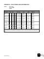
1
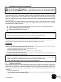
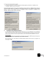
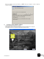
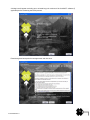
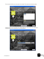
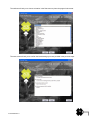
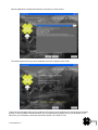
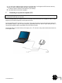
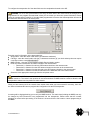
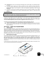
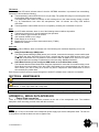
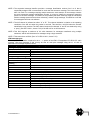
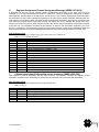
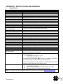
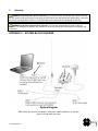
In the United States WARNING: It is a violation of the rules of the Federal Communications Commission to input an MMSI that has not been properly assigned to the end user, or to otherwise input any inaccurate data in this device. WARNING: This product is a supplemental navigation tool only! The user assumes all responsibility associated with the use of this device and safe navigation. It is important to understand that all vessels may not be equipped with AIS transponders and therefore may not be visible to this transponder. Likewise, certain conditions, such as equipment failures, the environment, improper use and crowded port scenarios, may exist whereby the vessel equipped with this AIS transponder is not visible to other AIS transponders. CAUTION: Before proceeding to install, test or use your new ACR Electronics‟ product, please read this Product Support Manual in its entirety. If you have questions regarding the contents of the manual, please contact our Technical Service Department at ACR Electronics, Inc., Telephone +1 (954) 981- 3333. Please be ready to provide the technician with the page number you wish to discuss. If you have a question that is not covered in the manual, please visit our website and access the Frequently Asked Questions (FAQs) section for further information or call our Technical Services Department. The website address is www.acrelectronics.com. If in the future you lose this manual, you may access and print a replacement on the ACR website. . 2 Y1-03-0222 Rev. C Table of Contents SECTION 1 - WHAT IS AIS? ____________________________________________________________ 4 SECTION 2 - INSTALLATION ___________________________________________________________ 6 SECTION 3 - USING THE TRANSPONDER ________________________________________________ 20 SECTION 4 - MAINTENANCE _________________________________________________________ 22 APPENDIX A - SERIAL DATA INTERFACE _________________________________________________ 22 APPENDIX B - SPECIFICATIONS AND WARNINGS __________________________________________ 28 APPENDIX C - SYSTEM BLOCK DIAGRAM ________________________________________________ 29 APPENDIX D - DATA POWER CABLE INFORMATION _______________________________________ 30 APPENDIX E - SUPPORT, WARRANTY, USEFUL LIFE and NOTICES _____________________________ 31 PLEASE READ ALL WARNINGS, CAUTIONS AND NOTES CAREFULLY 3 Y1-03-0222 Rev. C SECTION 1 - WHAT IS AIS? 1. Overview AIS is an acronym for Automatic Identification System. AIS increases navigational safety and collision avoidance by transmitting vessel identification, helping to reduce the difficulty of identifying ships when not in sight (e.g. at night, in radar blind arcs or shadows or at distance) by broadcasting navigational intentions to other vessels by providing ID, position, course, speed and other ship data with all other nearby ships and land based stations. According to International Association of Marine Aids to Navigation and Lighthouse Authorities (IALA) regulations, AIS is defined as follows: AIS is a broadcast transponder system, operating in the VHF maritime mobile band. It is capable of sending ship information such as identification, position course, speed and more, to other ships and to shore. It can handle multiple reports at rapid update rates and uses Carrier Sense Time Division Multiple Access (CSTDMA) technology to meet these high broadcast rates and ensure reliable and robust ship to ship operation. The International Maritime Organization (IMO) defines the performance standards as follows: Ship to ship working, ship to shore working, including long range application, automatic and continuous operation, provision of information messaging via PC and utilization of maritime VHF channels The Modules: GPS system, AIS Transponder, VHF Antenna, and the Data Power Cable (appropriate application software connects the individual modules). AIS are required to function flawlessly in a variety of modes. The regulations require that the system be capable of: An "autonomous and continuous" mode for operation in all areas. This mode shall be capable of being switched to/from one of the following alternate modes by a competent authority; An "assigned" mode for operation in an area subject to a competent authority responsible for traffic monitoring such that the data transmission interval and/or time slots may be set remotely by that authority; A "polling or controlled" mode, where the data transfer occurs in response to interrogation from a ship or competent authority. This illustration depicts a typical AIS System, where two or more AIS equipped vessels (and shore based systems) are automatically communicating with each other. 4 Y1-03-0222 Rev. C On the bottom, a typical Nauticast™-B AIS installation in a common environment is shown. The Nauticast™-B AIS is connected to the vessel‟s power supply, and, in connection with the VHF and GPS antennas, the minimal requirements for transponder operation are fulfilled. Both vessels in the above illustration are equipped with an AIS transceiver. Due to “Time – Synchronization”, they use the same organization of free and allocated windows (slots) in the shared VHF Data Link (this method is called “Carrier Sense Time Division Multiple Access”) to send and receive messages. Without the necessity of any operator interaction, both vessels know exactly who or what is cruising nearby and where the individual object is heading. The scenario below shows a full AIS coverage area (including all applications and complete shore infrastructure). 2. AIS classes There are two classes of AIS units fitted to vessels, Class A and Class B. In addition, AIS base stations may be employed by the Coast Guard, port authorities and other authorized bodies. AIS units acting as Aids to Navigation (A to N) can also be fitted to fixed and floating navigation markers such as channel markers and buoys. Class A units are a mandatory fit under the Safety of Life at Sea (SOLAS) convention to vessels above 300 gross tons, or which carry more than 11 passengers in international waters. Many other commercial vessels and some leisure craft also may be fitted with Class A units. Class B units are designed for fitting in vessels which do not fall into the mandatory Class A fit category. The ACR Nauticast™-B Automatic Identification System is a Class B AIS unit. 5 Y1-03-0222 Rev. C In order to meet carriage requirements for Class A and Class B AIS systems, dedicated GPS and VHF antennas must be fit to the transponders. ACR has included GPS and VHF antennas that have been specifically designed, tested and approved for use with the Nauticast™-B. ACR Electronics Inc. does not recommend or support using other antennas or sharing data information from existing shipboard installations. Class B AIS transponders will transmit data to other AIS equipped vessels and shore base stations. Static data typically identifies the vessel and does not change (i.e. MMSI, Vessel Name). Dynamic data is voyage specific and will change during the normal operation of the vessel.(i.e. Speed Over Ground, Position, Heading). In order to complete the programming of your AIS transponder, documentation of your vessel‟s identity needs to be made available. This would be a good time to update any information that is inaccurate in the MMSI data base or with your ship‟s radio station license. These databases should be reviewed periodically to make sure the information is accurate including your emergency contact information. Per FCC rules (United States users only) the static data can only be programmed into an AIS Transponder by the vendor or qualified personnel. Once the static data is programmed into an AIS Transponder it can only be corrected by ACR Electronics. Please check that the static data are entered carefully. If the static data are incorrectly programmed the transponder will need to be returned to ACR for factory reset. Information transmitted from vessels that have a Class A AIS transponders on-board include: • Name of Vessel • Destination • Size of Vessel • Vessel Dimensions • Speed (SOG) • Call Sign • ETA • Draft • Position • Course (COG) • Type of Vessel • Status • MMSI Number • Navigational Status • Heading • Cargo • Rate of Turn • IMO Number Information transmitted from vessels that have a Class B AIS transponders on-board include: • Name of Vessel • Vessel Dimensions • Speed (SOG) • Type of Vessel NOTE: For information reporting • Position • Heading intervals, see Specifications appendix • MMSI Number • Course (COG) • Call Sign NOTE: The marine AIS system uses position information derived from networks such as the Global Positioning Satellite (GPS) or the Global Navigation Satellite System (GLONASS) to determine the location of the AIS unit and thus the vessel to which it is fitted. The Nauticast™-B AIS utilizes the GPS satellite network. It is desirable wherever possible therefore to verify both your vessel‟s AIS derived position data and other vessels‟ AIS derived position data with visual or radar based observations. SECTION 2 - INSTALLATION 1. Product contents Before proceeding with the installation of the Nauticast™-B AIS, please verify that the content of the box includes the following: Nauticast™-B AIS transponder Data/Power cable Mounting hardware (4 self tapping screws) Strain relief cable straps (3) VHF antenna (dedicated for AIS use only) with connection cable GPS antenna (dedicated for AIS use only) with connection cable Nauticast™-B AIS Product Support Manual Nauticast™-B Mounting Template Link2AIS™ Software CD Link2AIS™ Software User Guide Warranty card 6 Y1-03-0222 Rev. C 2. Installation overview and prerequisites In the United States WARNING: It is a violation of the rules of the Federal Communications Commission to input an MMSI that has not been properly assigned to the end user, or to otherwise input any inaccurate data in this device. The US FCC regulation states that “The entry of static data into a Class B AIS device shall be performed by the vendor of the device or by an appropriately qualified person in the business of installing marine communications equipment on board vessels. In no event shall the entry of static data into a Class B AIS device be performed by the user of the device or the licensee of a ship station using the device. Knowingly programming a Class B AIS device with inaccurate static data, or causing a Class B AIS device to be programmed with inaccurate static data, is prohibited.” In the USA, some of the following steps must be performed by your vendor or a professional installer. Outside of the USA, the owner may perform all of these steps. The installation process has four separate steps. Complete each step before proceeding to the next. Compile ship‟s static data for installation (MMSI, vessel name, call sign, AIS GPS antenna position) Have static data programmed into transponder Install the Link2AIS™ Software onto your PC. Install your AIS hardware to your vessel. NOTE: In most countries the operation of an AIS unit is included under the vessel‟s marine VHF license provisions. The vessel onto which the AIS unit is to be installed must therefore possess a current VHF Ship station license which lists the AIS system and the vessel Call Sign and MMSI number. Please contact the relevant authority in your country for more information. The application will install and launch automatically. A Start Menu folder and shortcut will be created with the name 'Link2AIS'. This short cut should be used to re-launch the application as required. Prerequisites The Link2AIS™ Software is designed to operate with Microsoft Windows® 2000 (SP 3), Windows® XP (SP 2) and above. Recommended minimum system requirements are: Microsoft Windows® 2000 SP3 or Microsoft Windows® XP SP2 Display resolution of at least 1024 x 768 At least one RS232 serial port (or serial to USB converter already installed) A pointing device (mouse or equivalent) This software uses the Microsoft .NET® connection software V2.0. The framework will be automatically installed during setup if not already present on the system. NOTE: In most countries the operation of an AIS unit is included under the vessel‟s marine VHF license provisions. The vessel onto which the AIS unit is to be installed must therefore possess a current VHF Ship station license which lists the AIS system and the vessel Call Sign and MMSI number. Please contact the relevant authority in your country for more information. 3. Software installation Before installing a new version it may be necessary to remove any prior version of the Link2AIS™ software from your PC. When the old version cannot be overwritten, the installation program tells you to uninstall the previous version first. The program can be removed (uninstalled) at any time using the uninstall feature located in the program directory within the start menu (if applicable) or with the “Add or Remove Programs” function within Windows®. Insert the installation CD. If the installation does not start automatically, locate the file “setup.exe” on the CD-ROM drive and doubleclick on this file to start the installation process. 7 Y1-03-0222 Rev. C Or, when you have downloaded an upgrade: Unzip the package when necessary and start the installer program as described in “Installation of the Link2AIS™ Software” (later in this section). If one of the following dialogs is shown when the installation process is started, the .NET® framework and/or the Windows® Installer needs to be installed. See the following sections for the installation of these required products. If neither of these dialogs is shown, the installation continues as described in “Installation of the Link2AIS™ Software Program” (later in this section). 4. Installation of the .NET® Framework You may install the .NET® framework from the original CD or you can download it from the Microsoft website. When downloading the .NET® framework or the Windows® Installer manually, you need to look for version 2 of the “dotnetfx.exe” and the required installer, named “WindowsInstaller-KB893803-v2-x86.exe”. From the internet The Link2AIS™ software will automatically find, download, and install the .NET® framework directly from the Microsoft website if your computer has an active internet connection. When downloading over a 56k-modem, the .NET® framework will take about one hour to complete: The size is approx. 23MB. 8 Y1-03-0222 Rev. C When you are not connected to the internet, an error message like the one below will be shown. From the CD If you do not want to download the .NET® framework from the Microsoft website, terminate the download process by clicking the “Cancel” button in the download dialog box and install the package directly from the CD. Locate the file “dotnetfx.exe” and double-click it to start the installation. Follow the instructions. 5. Installation of the Windows Installer Locate the file “WindowsInstaller-KB893803-v2-x86.exe” and double-click it to start the installation. 9 Y1-03-0222 Rev. C When the installation process has finished, you MUST reboot your computer in order to install the Link2AIS™ Software: 6. Installation of the Link2AIS™ Software Unzip the downloaded package when necessary. Locate the files “setup.exe” and the accompanying “msi” file, then double-click on “setup.exe” The installation process of the application starts with the Welcome screen: 10 Y1-03-0222 Rev. C A dialog box will appear reminding you to uninstall any prior versions of the Link2AIS™ software (if applicable) before continuing the install process. Read through and accept the license agreement and click Next. 11 Y1-03-0222 Rev. C The next screen will allow you to pick options to be installed. These options are checked by default. Choose a directory where the software will be installed. Make note of this directory, as you will need to manually copy files to this location later on in the install process. 12 Y1-03-0222 Rev. C The software will ask you to choose a location in the Start menu to place the program‟s shortcuts: The next screen will ask you to confirm the install settings you have provided in the previous steps: 13 Y1-03-0222 Rev. C Now the application will install automatically in the folder you have chosen: The install program will tell you when installation has been completed. Click Finish. Finally, find the Coastlines folder on the installation CD and copy to the install directory chosen during the install process. If you are unable to find this directory, you can right-click the program icon on your desktop or in the Start menu, go to Properties, and look at the location shown in the “Start In” field. 14 Y1-03-0222 Rev. C You will find the installed program shortcuts in the Start Menu / All Programs/ ACR Electronics directory (unless you chose a different location during the install process). A shortcut named “Link2AIS” will be placed on your desktop. Use either shortcut to launch the program. 7. Connecting to a personal computer (PC) NOTE: To program your Nauticast™-B AIS you will need to connect the AIS to a personal computer and supply the Nauticast™-B AIS with 12V of power. ACR recommends that you connect the AIS to your boat‟s power and connect it to a laptop in order to easily program your AIS before physically mounting the transceiver. Connect the RS232 (9-Pin Connector) to your laptop. This connects between the supplied data lead and the PC. See illustration below. If the PC being used for programming does not have a 9-pin serial port then a commercially available USB to serial adaptor (RS 232) may be required. Connect the AIS to your boat‟s interior power supply (12 V). The red wire is the positive lead and the black wire is the negative lead. 15 Y1-03-0222 Rev. C Start up Link2AIS™ Software program on PC. The initial application screen will appear as shown: The application requires a serial connection to a Nauticast™-B AIS transponder. Connect the transponder to an available serial port. If your serial port is not located in the drop down box, select „New…‟ and create a new connection. Select the serial port from the drop down menu, then click 'Connect': Once a connection is established, the application is ready to use. Connection status is indicated at the bottom left of the application window: 8. Help file There is a context based Help file which explains what each data entry field means and what sort of data is expected. 9. Software structure The functions of Link2AIS™ Software are arranged in a series of tabs. Each tab contains information relating to a particular aspect of the connected AIS transponder. Depending on the version of Link2AIS™ Software installed, not all tabs shown below may be visible. 10. INSTALLERS ONLY: Entering static data Select the Monitoring tab and open the static data tab. This will display the static data for the connected AIS transponder. This includes the vessel's name, call sign, MMSI number and other fixed information. 16 Y1-03-0222 Rev. C To configure the transponder all of the data fields must be completed and saved to the AIS. WARNING: Per FCC rules (United States users only) the static data of the vessel cannot be changed once programmed. Do not program the static data unless you are certain you have the correct information. Please check the number entered carefully. If the static data programmed is incorrect the AIS transponder will need to be returned to ACR Electronics for factory reset. Enter the vessel‟s information in the appropriate box: Ship's name - enter the name of the vessel (20 characters maximum) Call Sign - enter the vessel's radio call sign (7 characters maximum) (If your local authority does not require a call sign number, enter @@@@@@@) MMSI number - enter the vessel's Maritime Mobile Service Identity number Enter the vessel‟s dimensions as follows rounded to the nearest meter o Dimension A - distance from bow to GPS antenna location to the nearest meter o Dimension B - distance from the GPS antenna location to the stern to the nearest meter o Dimension C - distance from the port side to the GPS antenna location to the nearest meter o Dimension D - distance from the GPS antenna to the starboard side to the nearest meter Select the most appropriate vessel type from the drop down menu CAUTION: If no MMSI is entered then the AIS transponder will operate in receive only mode and the red LED will remain on. The vessel‟s own position will not be transmitted. An MMSI must be entered to allow the AIS transponder to transmit its own position to other vessels. When you have entered all of the vessel's data, double-check what you have entered for accuracy, then click the 'Save to Nauticast-B' button to program this configuration into the AIS transponder: A warning will be displayed asking you to verify the MMSI number. The static data (including the MMSI) can only be changed by ACR Electronics once programmed into the transponder. Please check that the number displayed is correct before proceeding. If the number is incorrect click the 'No' button to cancel programming of the MMSI. 17 Y1-03-0222 Rev. C Click the 'Yes' button if the MMSI is correct. The static data tab will be updated to show the newly programmed vessel information. The MMSI number will be displayed with a grey background to indicate that it has been programmed and cannot be changed. For additional software applications unrelated to the installation, please refer to the Link2AIS™ Software user guide for technical support. 11. Hardware installation WARNING: The compass safe distance of this unit is 0.5m or greater for 0.3° deviation. WARNING: Do not connect the Nauticast™-B AIS unit to a main (line) AC electrical supply, as an electric shock or fire hazard could result. Length of data/power cable connection must not exceed 3 meters. CAUTION: Do not connect the Nauticast™-B AIS unit to a DC supply exceeding 15.6 V or reverse the supply polarity. Damage to the unit may result. Ensure the power supply is limited in accordance with EN 609501:2006 and protected with fuse or breakers not to exceed the specifications listed in this manual. CAUTION: The Nauticast™-B AIS unit is designed for operation in the temperature range -25 °C to +55 °C. Do not install (or use) the Nauticast™-B AIS unit in environments which exceed this range. CAUTION: Do not install the Nauticast™-B AIS unit in an environment where it can be subject to excessive exposure to water. Electrical connections WARNING: Only the data and power cables provided with the Nauticast™-B AIS unit should be used to connect antennas, power and display devices so as to maintain the integrity of the enclosure. Please see the Appendix section of this manual for details of the power, data and RF cables supplied. Using the two co-axial leads supplied, connect the down-lead from a VHF antenna to the VHF antenna port and connect the down-lead of a GPS antenna to the GPS antenna port. Please see Appendix A for a block diagram of the antenna installation. If an external display unit (AIS capable chart plotter, MKD, etc.) is to be used, connect the data interface cable to the NMEA port. Depending on your model chart plotter, a NMEA multiplexer capable of handling AIS data (38,400 baud) may be required. Consult the chart plotter manufacturer‟s support materials for interface instructions. 18 Y1-03-0222 Rev. C If using PC serial terminal with third party AIS capable Electronic Charting Software, connect the user end of the data interface cable to the display device. The software in the display device must be configured for AIS operation AND to accept standard Class B AIS operation NMEA sentences. This external display unit software is not part of the Nauticast™-B AIS transponder package. By rule, Class B AIS devices must output serial data. If your computer only has a USB port, you must use a serial-to-USB adapter, available at most consumer electronic retailers. The Nauticast™-B requires a 12V DC power supply (9.6 – 15.6V) capable of supplying 2A peak surge. The power supply is a two wire system where the red wire is the positive lead and the black wire is the negative lead. The Nauticast™-B should be connected to the vessel‟s fuse panel that is supplied by the ship‟s 12V batteries. CAUTION: If the vessel uses an AC generator that converts to DC power, the Nauticast™-B should be fully isolated from this system with the use of a fully isolated DC/DC converter. Physical mounting The unit shall be mounted on a vertical bulkhead with the cables in the down position. The mounting location should be protected from the weather and direct water spray. Typically this would be under the helm station or in the cabin. It is recommended that the unit is attached to a solid surface with #10-32 x 1.2 self tapping head Phillips screws (provided in kit). A template for drilling pilot holes is included in this kit. WARNING: The compass safe distance of this unit is 0.5m or greater for 0.3° deviation. 12. Antenna installation Antenna connections on the transponder GPS antenna This is a TNC female bulkhead connector that mounts to the side of the transponder case. This port provides the 5V DC feed for the active GPS antenna required by the Nauticast™-B AIS unit. VHF antenna This is a UHF female PL-259 bulkhead connector that mounts to the side of the transponder case. CAUTION: The GPS, VHF and power/data cables need to be secured to the bulkhead within 6” to 12” from the connectors. Avoid excess stress on connectors during installation. Strain relief should be used. Antenna mounting GPS antenna for AIS use NOTE: If you are installing a Class B AIS transponder on a vessel because you are required to do so, you must use a separate VHF antenna and a separate GPS antenna dedicated to the Class B device in order to be compliant with the regulations. Use the antennas supplied with this kit. The GPS antenna supplied for use with the Nauticast™-B is an active type (i.e. it includes LNA) and is suitable for marine shipboard applications (index of protection, ruggedness, means of mounting, ect). The supplied antenna supplies a minimum gain of 20dB to the Nauticast™-B after subtraction of the normal loss from antenna cable and connectors. The GPS antenna used for any AIS must be a dedicated antenna , i.e. not shared with any other GPS receiver. Installation of the GPS antenna is critical for the performance of the built in GPS receiver which is used for timing of the transmitted time slots and for the supply of navigational information should the ships main navigational GPS fail. It is strongly recommended that: The GPS antenna is mounted in an elevated position and free of shadow effect from the ship‟s superstructure. 19 Y1-03-0222 Rev. C The GPS antenna has a free view through 360 degrees with a vertical angle of 5 to 90 degrees above the horizon. The GNSS antenna is placed as far away as possible from radar, Inmarsat and Iridium transmitters. Also ensure that the GPS antenna is free from direct view of the radar and the Inmarsat beam. The received GPS signal is very sensitive to noise and interference generated by other onboard transmitters. The MF/HF and other VHF transmitter antennas are kept as far away as possible from the GNSS antenna. It is good practice never to install a GNSS antenna within a radius of 2 meters from these antennas. VHF antenna for AIS use NOTE: If you are installing a Class B AIS transponder on a vessel because you are required to do so, you must use a separate VHF antenna and a separate GPS antenna dedicated to the Class B device in order to be compliant with the regulations. Use the antennas supplied with this kit. The VHF antenna supplied for use with the Nauticast™-B is omni-directional, vertically polarized with unity gain (0 dB) and a band width sufficient to maintain VSWR <1.5 over the frequency range 156–163 MHz. As a minimum the 3dB bandwidth will cover the two AIS channels and the DCS channel. The antenna is also suitable for marine shipboard applications (index of protection, ruggedness, means of mounting, etc.). If you elect to not use the antenna supplied, the alternate VHF antenna employed for AIS use: Must be a dedicated antenna, i.e. not shared with any other VHF transmitter/receiver. Should be mounted with at least a two meter vertical separation distance from any other VHF antenna used for speech or DCS communication. Also see Appendix for warnings such as “Radio Frequency Exposure Warning”. SECTION 3 - USING THE TRANSPONDER 1. Switching ON When the 12V supply is switched on, all four LEDs visible on the front panel of the unit will illuminate twice for a period of one second on each illumination. The blue LED will then go out. When the internal GPS starts outputting valid position information, the red LED will go out. When the Nauticast™-B AIS unit transmits its first position report (message 18), the yellow LED will go out. Note that this process may take up to 30 minutes depending on the switch-on state of the GPS receiver. When the yellow LED goes out the green LED will illuminate indicating that the unit is now operating correctly. 2. Warning and fault states If the unit has not been able to transmit a position report during the last expected two reporting intervals (i.e. the nominal reporting interval cannot be maintained for operational reasons such as a Message 23 quiet period, high channel load conditions, etc.) the yellow LED will illuminate. This is a warning condition only and indicates that your vessel‟s position is not currently being reported to other vessels. Reception of other vessel AIS information by the Nauticast™-B AIS is not affected. When the unit is able to commence reporting, the yellow LED goes out. If a fault occurs the red LED will illuminate. This may illuminate briefly if the power supply is interrupted or if the VHF or GPS antenna characteristics are briefly affected. 20 Y1-03-0222 Rev. C If the red LED illuminates continuously, the unit should be assumed to be faulty. It should either be switched off (power removed) or, if this is not practical, any other vessel position information derived from the unit should not be used. It should also be assumed that the unit is not transmitting valid position information for your vessel. The unit should be examined by a competent equipment maintainer at the earliest opportunity. More details on LED indications can be found in “LED Indicators” (below). 3. Data port messages The data port will output the following: (At power-up) boot-loader and main application splash text screens including version numbers, and memory status Details of relevant AIS transmissions received Details of AIS transmissions sent Details of channel management messages received Alarm messages generated by the BIIT function The data port will accept the following inputs: Programming information Alarm acknowledgements Please see the ‘Data Interface’ section of this manual for more details of the data port messages. When in operation, an AIS unit: Uses one of two VHF channels within the international marine band allocation (channel 87B; 161.975MHz, or channel 88B; 162.025MHz) to regularly transmit information such as the vessel position, Maritime Mobile Service Identity (MMSI), name, speed, course, etc. Receives similar information from other AIS equipped vessels within VHF range and outputs that information for use by an external display medium (AIS enabled chart plotter, PC using AIS enabled chart plotter software etc.) 4. Built-in test The Nauticast™-B AIS unit is equipped with Built in Integrity Testing (BIIT). BIIT tests run continuously or at appropriate intervals simultaneously with the standard functions of the equipment. The BIIT detects any failure or malfunction that will significantly reduce integrity or stop operation of the Nauticast™-B AIS unit. The tests include: AIS TX malfunction (synthesizer not locked and TX time-out not exceeded) Antenna VSWR exceeds limit Rx channel 1 malfunction (synthesizer not locked) Rx channel 2 malfunction (synthesizer not locked) Internal GNSS not in use No valid SOG information No valid COG information Background noise > -77dBm GPS failure VSWR exceeding the maximum allowed level The input voltage is out of the specified range 5. LED indicators Power This is a green LED which indicates, when lit, that power has been connected correctly to the transponder, that the transponder hardware has been configured, that the operating software is present, that the CPU has booted up and the application software is running. 21 Y1-03-0222 Rev. C TX timeout This is a yellow LED which indicates when lit that the CSTDMA transmitter is prevented from transmitting. Reasons for this include the following: The transponder‟s internal GPS receiver is not yet ready. The yellow LED will go out and the green LED will light when GPS receiver is ready. The transponder was unable to transmit an AIS message due to the channel being already occupied, e.g. by transmissions from other AIS transponders. Wait 10 minutes and verify GPS antenna connection. The transponder‟s internal GPS receiver is not operating. Contact your local dealer for service. Error This is a red LED which indicates, when lit, one of the following status conditions is possible: Transmitter lockout timer (1 second maximum) has operated GPS is unable to gain lock after 30 minutes VHF antenna VSWR is out of range Power Supply is out of range Background noise level is above the threshold level (-77dBm) MMSI is not entered Blue LED The unit has a blue LED that, when lit, indicates one of the following two conditions depending on how it is programmed: Safety Related Message (SRM) status The Safety Related Message (SRM) button (not included, recommend momentary contact switch rated for > 25mA) has been depressed for more than 2 seconds and the pre-set SRM has been sent. If the SRM LED is illuminated it is not possible to send another SRM. An SRM can be sent once a minute. The payload within the message 14 transmission is the text string “MAYDAY MAYDAY”. Silent Mode Function (if user configures SRM switch to act as Silent Mode switch) This indicates that the Silent Mode button has been depressed for more than 2 seconds and the pre-set Silent Mode has been activated. If the blue LED is illuminated you are not transmitting your AIS data to other vessels, your AIS is acting as a receive-only device. Depress the Silent Mode button a second time transmit your position data. Both of these functions can be accessed through the Link2AIS™ software when a switch is not installed. SECTION 4 - MAINTENANCE WARNING: Unauthorized opening of the Nauticast™-B AIS system will invalidate the warranty. CAUTION: Avoid using chemical solvents to clean the Nauticast™-B AIS as some solvents can damage the case material. To clean, wipe down with a damp cloth. NOTE: The Nauticast™-B AIS contains no user serviceable parts. Contact your Service Agent for repair. APPENDIX A - SERIAL DATA INTERFACE 1. Power/ Data connection There is a 15-pin D-Sub female connector mounted on the side of the transponder case. The standard data/power cable assembly provided mates with this connector. NOTE: Both thumb screws on the power/data cable will be tightened securely. Power 12V DC (9.6-15.6V) is connected to the transponder power supply input via the data/power cable. The red wire is the positive lead and the black wire is the negative lead. 22 Y1-03-0222 Rev. C Data A minimum keypad and display (MKD) unit, chart plotter or other display device may be connected to the Nauticast™-B AIS unit via the appropriate cable assembly. The default baud rate of the data link is 38.4k baud with 8 data bits, one stop bit and no parity. The data interface conforms to IEC 61162-1. VDM, VDO, ACA, ACS, ALR, TXT and ACK messages conform to NMEA 0183. Please refer to NMEA 0183 for full details of these AIS messages. 2. Serial Port Input/Output There is one 9-pin serial port for data in RS232 format. There is one set of flying leads for data in RS422 format. Duplex capability is available from either or both ports. The serial port interface(s) output: At power-up, boot-loader and main application splash text screens including version numbers and memory status. As a VHF Data Link Message (VDM) all incoming VHF Data Link (VDL) data received by the Nauticast™-B AIS. The VHF data link own vessel (VDO) messages sent by the Nauticast™-B AIS over the VHF Data Link. AIS regional channel assignment messages (ACA) received. These are derived from an incoming VHF Data Link message (message 22) or a DSC message. AIS channel management information source (ACS) messages. Alarm messages (ALR, TXT). The data interface will accept: Personality programming messages Alarm acknowledgement messages (ACK) 3. Power up messages On power up, the unit will report details of the firmware versions residing in the unit. 4. VHF data link messages (NMEA 0183 VDM) This sentence is used to transfer the receipt of a VHF Data Link (VDL) message on either AIS radio channel, as defined in ITU-R M.1371, using the “Six-bit” field type. The structure provides for the transfer of long binary messages by using multiple sentences. Data messages should be transmitted in as few sentences as possible. When a data message can be accommodated in a single sentence, it is not split. VDM message format !--VDM,x1,x2,x3,a,s--s,x*hh<CR><LF> field 1 2 3 4 5 6 Field 1 2 3 4 5 6 Format x x x a s---s x Description 1 Total number of sentences needed to transfer the message , 1 to 9 1 Sentence number , 1 to 9 2 Sequential message identifier , 0 to 9 3 AIS Channel, "A" or "B" 4 Encapsulated ITU-R M.1371 radio message 5 Number of fill-bits , 0 to 5 NOTE 1 The length of an ITU-R M.1371 message may require the transmission of multiple sentences. The first field specifies the total number of sentences used for a message, minimum value 1. The second field identifies the order of this sentence in the message, minimum value 1. These cannot be null fields. 23 Y1-03-0222 Rev. C NOTE 2 The sequential message identifier provides a message identification number from 0 to 9 that is sequentially assigned and is incremented for each new multi-sentence message. The count resets to 0 after 9 is used. For a message requiring multiple sentences, each sentence of the message contains the same sequential message identification number. It is used to identify the sentences containing portions of the same message. This allows for the possibility that other sentences might be interleaved with the message sentences that, taken collectively, contain a single message. This shall be a null field for messages that fit into one sentence. NOTE 3 The AIS channel is indicated as either “A” or “B”. This channel indication is relative to the operating conditions of the AIS unit when the packet is received. This shall be a null field when the channel identification is not provided. The VHF channel numbers for channels “A” and “B” are obtained by using a “query” (See IEC 61162-1, clause 5.3.2) of the AIS unit for an ACA sentence. NOTE 4 This field supports a maximum of 62 valid characters for messages transferred using multiple sentences, and 63 valid characters for messages using a single sentence. NOTE 5 This cannot be a null field. (See “x4” in IEC 61162-1, clause 5.3.3). VDM message types For example, the information contained in the s - - s portion of the VDM = Encapsulated ITU-R M.1371 radio message. Note that messages 5 and 19 may be sent as multi part messages using the x1, x2 and x3 parameters for message sequence control. VDL Message number VDM Message description AIS Target Display Information 1, 2, 3, 9,18, 21 position report 4 base station report 5* voyage related data 19* Class B – extended data Safety message handling 12 addressed safety related 14 broadcast safety related External Application handling 6 binary addressed 8 binary broadcast System control 7 binary acknowledge (INFO) 10 UTC and data inquiry (INFO) 11 UTC and data response (INFO) 13 safety related ack (INFO) 15 interrogation (INFO) 16 assignment mode command (INFO) 17 DGNSS corrections (INFO) 20 data link management (INFO) 22 channel management (INFO) *Note that messages 5 and 19 may be sent as multi part messages. 24 Y1-03-0222 Rev. C 5. VHF data link own vessel messages (NMEA 0183 VDO) This message describes your own vessel message being sent. VDO message format !--VDO,x1,x2,x3,a,s--s,x*hh<CR><LF> field 1 2 3 4 5 6 Field 1 2 3 4 5 6 Format x x x a s---s x Description 1 Total number of sentences needed to transfer the message , 1 to 9 1 Sentence number , 1 to 9 2 Sequential message identifier , 0 to 9 3 AIS Channel, "A" or "B" 4 Encapsulated ITU-R M.1371 radio message 5 Number of fill-bits , 0 to 5 NOTE 1 The length of an ITU-R M.1371 message may require the transmission of multiple sentences. The first field specifies the total number of sentences used for a message, minimum value 1. The second field identifies the order of this sentence in the message, minimum value 1. These cannot be null fields. NOTE 2 The Sequential message identifier provides a message identification number from 0 to 9 that is sequentially assigned and is incremented for each new multi-sentence message. The count resets to 0 after 9 is used. For a message requiring multiple sentences, each sentence of the message contains the same sequential message identification number. It is used to identify the sentences containing portions of the same message. This allows for the possibility that other sentences might be interleaved with the message sentences that, taken collectively, contain a single message. This shall be a null field for messages that fit into one sentence. NOTE 3 The AIS channel is indicated as either “A” or “B”. This channel indication is relative to the operating conditions of the AIS unit when the packet is received. This shall be a null field when the channel identification is not provided. The VHF channel numbers for channels “A” and “B” are obtained by using a “query” (See IEC 61162-1, clause 5.3.2) of the AIS unit for an ACA sentence. NOTE 4 This field supports a maximum of 62 valid characters for messages transferred using multiple sentences, and 63 valid characters for messages using a single sentence. NOTE 5 This cannot be a null field. (See “x4” in IEC 61162-1, clause 5.3.3). VDO Message number VDO Message description AIS Target Display Information 13 Safety Related Acknowledgement Standard Class B position report (Includes MMSI, SOG, position accuracy, lat, 18 long, COG, true heading,) 24a Class B “CS” Static data Part A (Includes MMSI and vessel name) 24b Class B “CS” Static data Part B (MMSI, ship type, cargo type, call sign, ship dimensions) 25 Y1-03-0222 Rev. C 6. Regional Assignment Channel Assignment Message (NMEA 0183 ACA) A Nauticast™-B unit can receive regional channel management information in two ways: ITU-R M.1371 message 22 or a DSC telecommand received on channel 70. Channel management information is applied based upon the actual location of the AIS device. An AIS unit is “using” channel management information when the information is being used to manage the operation of the VHF receiver and/or transmitter inside the AIS unit. This sentence is used both to enter and obtain channel management information. When sent to an AIS unit, the ACA sentence provides regional information that the unit stores and uses to manage the internal VHF radio. When sent from an AIS unit, the ACA sentence provides the current channel management information retained by the AIS unit. The information contained in this sentence is similar to the information contained in an ITU-R M.1371-1 message 22. The information contained in this sentence directly relates to the Initialization Phase and Dual Channel Operation and Channel Management functions of the AIS unit as described in ITU-R M. 1371. ACA message format $--ACA,x,llll.ll,a,yyyyy.yy,a,llll.ll,a,yyyyy.yy,a,x,xxxx,x,xxxx,x,x,x,a,x,hhmmss.ss field 1 2 3 4 5 6 7 8 91011121314 15 Field 1 2 3 4 5 6 7 8 9 10 11 12 13 14 15 7. Format x IIII, II, a yyyyy.yy,a IIII, II, a yyyyy.yy,a x xxxx x xxxx x x x a x hhmmss.ss Description Sequence Number , 0 to 9 Region Northeast corner latitude – N/S Region Northeast corner longitude – E/W Region Southwest corner latitude – N/S Region Southwest corner longitude – E/W Transition Zone Size Channel A Channel A bandwidth Channel B Channel B bandwidth Tx/Rx mode contro Power level control Information source In-Use Flag Time of "in-use" change Channel management information source messages (NMEA 0183 ACS) This sentence is used in conjunction with the ACA sentence. This sentence identifies the originator of the information contained in the ACA sentence and the date and time the AIS unit received that information. ACS message format !-- ACS,x,xxxxxxxxx, hhmmss.ss,xx,xx,xxxx*hh<CR><LF> field 1 2 3 4 5 6 Field 1 2 3 4 5 6 Format x xxxxxxxxx hhmmss.ss xx xx xxxx Description Sequence Number , 0 to 9 MMSI of originator UTC of receipt of channel management information UTC Day, 01 -31 UTC Month, 01 -12 UTC Year 26 Y1-03-0222 Rev. C 8. AIS alarm messages (NMEA 0183 ALR, Text) Local alarm condition and status. This sentence is used to report an alarm condition on a device and its current state of acknowledgement. ALR message format !-- ALR,hhmmss.ss,xxx,A,A,c--c*hh<CR><LF> field 1 2 3 4 5 Field 1 2 3 4 5 9. Format x Description hhmmss.ss = Time of alarm (UTC) Unique alarm number Alarm condition Alarm acknowledge state Alarm description, text Alarm descriptions presented are: AIS: TX malfunction AIS: Antenna VSWR exceeds limit AIS: Rx channel 1 malfunction AIS: Rx channel 2 malfunction AIS: general failure AIS: no sensor position in use AIS: no valid SOG information AIS: no valid COG information AIS: 12V alarm AIS: 5V alarm AIS: Loss of serial interface integrity AIS: Background noise above -77dBm ACK messages An Acknowledge Message (ACK) can be generated by a minimum keypad and display (MKD) unit, chart plotter or other display device connected to the Nauticast™-B to acknowledge an alarm condition reported by the Nauticast™-B. ACK message format !-- ACK,xxx*hh <CR><LF> field 1 Field 1 Format x Description unique alarm number 27 Y1-03-0222 Rev. C APPENDIX B - SPECIFICATIONS AND WARNINGS 1. Specifications Parameter Dimensions Weight Power GPS Receiver (AIS Internal) Electrical Interfaces Connectors Cable – Power/Data VHF Transceiver AIS1: 161.975 MHz AIS2: 162.025 MHz Output Power Channel Bandwidth Channel Step Modulation Modes Bit rate RX Sensitivity Environmental Indicators Operator Controls Information reporting intervals Approvals Value 7.8 x 6.22 x 1.84 in. (198 x 158 x 46.7 mm) 13.2 oz (375g) DC (9.6-15.6V), two-wire with negative ground Average power consumption 4W Peak current rating 2A IEC 61108-1 compliant RS232 38400bps bi-directional RS422 NMEA 38400bps bi-directional VHF Antenna connector (UHF female bulkhead connector) GPS Antenna connector (TNC female bulkhead connector) Power, RS232, RS422, SRM (15-pin Connector), 1.5 meter DSUB Transmitter x 1 Receiver x 2 (One receiver time shared between AIS and DSC) Frequency: 156.025 to 162.025 MHz in 25 kHz steps 33dBm ± 1.5 dB (2W) 25kHz 25kHz 25kHz GMSK (AIS, TX and RX) 25kHz AFSK (DSC, RX only) 9600 b/s ± 50 ppm (GMSK) 1200 b/s ± 30 ppm (FSK) Sensitivity – 107dBm 25kHz (Message Error Rate 20%) Co-Channel 10dB Adjacent Channel 70dB IMD 65dB Blocking 84dB IEC 60945 Operating Temperature: -25ºC to +55ºC IEC 62287, IP67 (with cables installed) Power, TX timeout, status, pre-set SRM sent or Silent Mode Optional pre-set safety related message (SRM) transmit button or Silent Mode -No Transmit (user Configured). The Nauticast™-B AIS will transmit position reports (Message 18) in reporting intervals of: Every 30 seconds if SOG is > 2 kn; Every 3 Minutes if SOG is < 2 kn Provided that the transmission time periods are available. A command received by Message 23 shall override the reporting interval. static data sub messages 24A and 24B will be transmitted every 6 minutes in addition to and independent of the position report. USCG Approval Number: 165.156/3/0 FCC ID B66ACR-AIS-300 R&TTE Phoenix (NB#0700) Certificate Number: 07-110244 BSH Approval Number: BSH/46162/4320519/2007 NOTE: For complete information regarding approvals, please visit ACR‟s website at www.acrelectronics.com 28 Y1-03-0222 Rev. C 2. Warnings WARNING regarding VHF antenna connection: Connecting a badly mismatched VHF antenna, leaving the VHF antenna port disconnected, or shorting the VHF antenna port will activate the VSWR alarm, causing the unit to stop sending position reports or causing damage to the transponder and activating the red LED. WARNING regarding radio frequency exposure: To meet the requirements for Radio Frequency Exposure it is necessary to install the VHF antenna correctly and operate the AIS equipment according to the instructions. APPENDIX C - SYSTEM BLOCK DIAGRAM System Diagram SRM Switch, PC, serial-to-USB adaptor, chart plotter, NMEA multiplexer not included (Mount unit with cable side down) 29 Y1-03-0222 Rev. C APPENDIX D - DATA POWER CABLE INFORMATION Class B Description A2-07-0196-1 DATA POWER CABLE J1 J2 DB15 DB9 Wire Type Color AWG CABLE # 12V + 1 Tinned Copper RED 18 CABLE1 12V - 9 Tinned Copper BLACK 18 CABLE1 RS422 TX A 2 Tinned Copper ORANGE 22-24 CABLE 2 RS422 RX A 3 Tinned Copper YELLOW 22-24 CABLE 2 RS422 TX B 10 Tinned Copper BLACK 22-24 CABLE 2 RS422 RX B 11 Tinned Copper WHITE 22-24 CABLE 2 SW1GND 15 Tinned Copper BLACK 22-24 CABLE 3 SW1 Switch 8 Tinned Copper PURPLE 22-24 CABLE 3 RS232 TX 12 2 Tinned Copper RED 22-24 CABLE 4 RS232 RX 13 3 Tinned Copper BLUE 22-24 CABLE 4 GND 14 5 Tinned Copper BLACK 22-24 CABLE 4 Note: Connectors J1 and J2 have shielded jackets with ground connection to metal shell of connector. Cable 2 and Cable 3 have staggered length clipped conductors to prevent shorting and are capped with heat shrink. 30 Y1-03-0222 Rev. C APPENDIX E - SUPPORT, WARRANTY, USEFUL LIFE and NOTICES 1. Support Contact your local dealer for Nauticast™-B AIS support. Please visit the ACR Website for Service centers near you. ACR Electronics Europe GmbH Handelskai 388 / Top 632 A-1020 Vienna, Austria Tel: +43 (1) 5 237 237 - 0 Fax: +43 (1) 5 237 237 - 150 Email: [email protected] Web: www.acr-europe.com 2. ACR Electronics Inc. Technical Service 5757 Ravenswood Road Fort Lauderdale, FL 33312, U.S.A. Tel.: +1 (954) 981-3333 Fax: +1 (954) 983-5087 Email: [email protected] Web: www.acrelectronics.com Limited WarrantyLimied Warranty This product is warranted against factory defects in material and workmanship for a period of 1 (one) year* from date of purchase or receipt as a gift. During the warranty period ACR Electronics, Inc. will repair or, at its option, replace the unit at no cost to you for labor, materials and return transportation from ACR. For further assistance, please contact our Technical Service Department at ACR Electronics, Inc., 5757 Ravenswood Road, Fort Lauderdale, FL 33312-6645. Email: [email protected], Fax: +1 (954) 983-5087, Telephone: +1 (954) 981- 3333. This warranty does not apply if the product has been damaged by accident or misuse, or as a result of service or modification performed by an unauthorized factory. Except as otherwise expressly stated in the previous paragraph, THE COMPANY MAKES NO REPRESENTATION OR WARRANTY OF ANY KIND, EXPRESS OR IMPLIED, AS TO MERCHANTABILITY, FITNESS FOR A PARTICULAR PURPOSE, OR ANY OTHER MATTER WITH RESPECT TO THIS PRODUCT. The Company shall not be liable for consequential or special damages. To place the warranty in effect, register online at www.acrelectronics.com or return the attached card within 10 days. *Five years for the following products: EPIRB, PLB, S-VDR, SSAS 3. Useful Life Policy The typical service life of a properly maintained Product is limited to 12 years from date of manufacture. Products that are 12 years and 1 month or older from date of manufacture will not be serviced by ACR or our Battery Replacement Centers. A Product that is 12 or less years old from date of manufacture will be serviced as long as the unit appears fit to be placed back into its final operational cycle. Service includes the replacement of those items that must be replaced at service intervals and the verification that the device appears to be in good mechanical and electrical working condition by an ACR authorized service technician. 4. Other notices ACR Electronics diligently works to provide a high quality Product Support Manual, however, despite best efforts, information is subject to change without notice, and omissions and inaccuracies are possible. ACR cannot accept liability for manual contents. To ensure that you have the most recent version of the Product Support Manual, please visit the ACR website at www.acrelectronics.com. In accordance with a policy of continual development and product improvement the Nauticast™-B hardware and software may be upgraded from time to time and future versions of the Nauticast™-B may therefore not correspond exactly with this manual. When necessary, upgrades to the product will be accompanied by updates or addendums to this manual. ©2008 by ACR Electronics, Inc., part of Cobham plc. All rights reserved. Reproduction in whole or in part is permitted only with permission of ACR Electronics, Inc. Ongoing product improvements may change product specifications without notice. Trademarks or registered trademarks are the property of their respective owners. 31 Y1-03-0222 Rev. C EC DECLARATION OF CONFORMITY ACR Electronics, Inc. hereby declares that the following product is in conformity with Directive 1999/5/EC of the European Parliament and of the Council of 9 March 1999 on Radio equipment and Telecommunications Terminal Equipment (R&TTE), and has been type examined as follows. In accordance with the Directive, the product will be marked with the CE conformity marking as follows: Product: Class B CSTDMA Automatic Identification System (AIS) Transponder Trade Name: Nauticast-B Model: AIS-300 Notified Body: Phoenix Testlab GmbH, Notified Body No. 0700 Königswinkel 10, D-32825 Blomberg, Germany Certificate No. 07-110244 Regulations and Standards: IMO MSC.74(69) Annex 3 ITU-R M.1371-1 (Class B) IALA Technical Clarification of ITU-R M.1371-1 (Ed. 1.4) ITU-R M.825-3 ITU-R M.1084-3 IEC 62287-1: 2006 IEC 60945: 2002 IEC 60950-1: 2006 IEC 61162-1: 2000 IEC 61162-2: 1998 IEC 61108-1: 2003 Manufacturer: ACR Electronics Inc. 5757 Ravenswood Road Fort Lauderdale, FL 33312 USA European Representative: ACR Electronics Inc. (European Office) 1 Rose Cottages, Pitmore Lane, Sway, Lymington, Hampshire SO41 6BX UK Signed on behalf of ACR Electronics, Inc. Signed: ___________________________________________ Name: Kerry Greer Date: July 1, 2008 Title: VP Engineering Document AIS-300-001 This Declaration complies with ISO/IEC 17050-1:2004 ACR Electronics, Inc. is registered by UL to ISO 9001:2000 32 Y1-03-0222 Rev. C