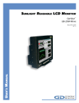
1
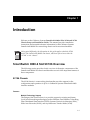
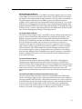
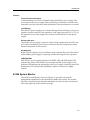
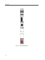
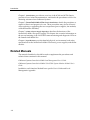
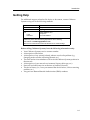
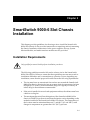
SmartSwitch 9000-6 Slot
9C106 and 9C706 Chassis
Setup and Installation Guide
9031993-02
Notice
Cabletron Systems reserves the right to make changes in speciÞcations and other information
contained in this document without prior notice. The reader should in all cases consult Cabletron
Systems to determine whether any such changes have been made.
The hardware, Þrmware, or software described in this manual is subject to change without notice.
IN NO EVENT SHALL CABLETRON SYSTEMS BE LIABLE FOR ANY INCIDENTAL, INDIRECT,
SPECIAL, OR CONSEQUENTIAL DAMAGES WHATSOEVER (INCLUDING BUT NOT LIMITED
TO LOST PROFITS) ARISING OUT OF OR RELATED TO THIS MANUAL OR THE INFORMATION
CONTAINED IN IT, EVEN IF CABLETRON SYSTEMS HAS BEEN ADVISED OF, KNOWN, OR
SHOULD HAVE KNOWN, THE POSSIBILITY OF SUCH DAMAGES.
© January 1999 by:
Cabletron Systems, Inc.
35 Industrial Way
Rochester, NH 03867
All Rights Reserved
Printed in the United States of America
Order Number: 9031993-02
Cabletron Systems and LANVIEW are registered trademarks and SmartSwitch 9000-6 is a trademark
of Cabletron Systems, Inc.
Ethernet is a trademark of Xerox Corporation.
i
Notice
FCC Notice
This device complies with Part 15 of the FCC rules. Operation is subject to the following two
conditions: (1) this device may not cause harmful interference, and (2) this device must accept any
interference received, including interference that may cause undesired operation.
NOTE: This equipment has been tested and found to comply with the limits for a Class A digital
device, pursuant to Part 15 of the FCC rules. These limits are designed to provide reasonable
protection against harmful interference when the equipment is operated in a commercial environment.
This equipment uses, generates, and can radiate radio frequency energy and if not installed in
accordance with the operatorÕs manual, may cause harmful interference to radio communications.
Operation of this equipment in a residential area is likely to cause interference in which case the user
will be required to correct the interference at his own expense.
WARNING: Changes or modiÞcations made to this device which are not expressly approved by the
party responsible for compliance could void the userÕs authority to operate the equipment.
VCCI Notice
This is a Class A product based on the standard of the Voluntary Control Council for Interference by
Information Technology Equipment (VCCI). If this equipment is used in a domestic environment,
radio disturbance may arise. When such trouble occurs, the user may be required to take corrective
actions.
Industry Canada Notice
This digital apparatus does not exceed the Class A limits for radio noise emissions from digital
apparatus set out in the Radio Interference Regulations of the Canadian Department of
Communications.
Le prŽsent appareil numŽrique nÕŽmet pas de bruits radioŽlectriques dŽpassant les limites applicables
aux appareils numŽriques de la class A prescrites dans le R•glement sur le brouillage radioŽlectrique
ŽdictŽ par le minist•re des Communications du Canada.
ii
Notice
DECLARATION OF CONFORMITY
Application of Council Directive(s):
ManufacturerÕs Name:
ManufacturerÕs Address:
European Representative Name:
European Representative Address:
Conformance to Directive(s)/Product Standards:
Equipment Type/Environment:
89/336/EEC
73/23/EEC
Cabletron Systems, Inc.
35 Industrial Way
PO Box 5005
Rochester, NH 03867
Mr. J. Solari
Cabletron Systems Limited
Nexus House, Newbury Business Park
London Road, Newbury
Berkshire RG13 2PZ, England
EC Directive 89/336/EEC
EC Directive 73/23/EEC
EN 55022
EN 50082-1
EN 60950
Networking Equipment, for use in a
Commercial or Light Industrial
Environment.
We the undersigned, hereby declare, under our sole responsibility, that the equipment packaged with
this notice conforms to the above directives.
Manufacturer
Legal Representative in Europe
Mr.
Ronald Fotino
___________________________________
Full Name
Mr. J. Solari
___________________________________
Principal
Compliance Engineer
___________________________________
Title
Managing Director - E.M.E.A.
___________________________________
Rochester,
NH, USA
___________________________________
Location
Newbury, Berkshire, England
___________________________________
Full Name
Title
Location
iii
Notice
iv
Contents
Chapter 1
Introduction
SmartSwitch 9000-6 Slot 9C106 Overview ................................................................ 1-1
9C106 Chassis ......................................................................................................... 1-1
Features ............................................................................................................ 1-1
The Backplane ................................................................................................. 1-2
9C206-1 Power Supply .......................................................................................... 1-4
Features ............................................................................................................ 1-5
9C306 System Monitor .......................................................................................... 1-5
Features ............................................................................................................ 1-7
How to Use This Manual ............................................................................................. 1-7
Related Manuals............................................................................................................ 1-8
Getting Help .................................................................................................................. 1-9
Chapter 2
SmartSwitch 9000-6 Slot Chassis Installation
Installation Requirements ............................................................................................ 2-1
Unpacking the SmartSwitch 9000-6 Slot Chassis ..................................................... 2-2
Rack Mounting the SmartSwitch 9000-6 Slot Chassis.............................................. 2-3
Installing a Power Supply............................................................................................ 2-5
Installing the 9C306 System Monitor ......................................................................... 2-7
Installing a Fan Module ............................................................................................... 2-8
Installing SmartSwitch 9000-6 Slot Interface Modules .......................................... 2-10
Powering Up the SmartSwitch 9000-6 Slot Chassis ............................................... 2-11
Chapter 3
9C206-1 Power Supply Operation
9C206-1 Power Supply LANVIEW LEDs .................................................................. 3-1
PWR Status LED .................................................................................................... 3-2
Power Supply Level Indicator LED .................................................................... 3-3
Power Redundancy LED ...................................................................................... 3-3
Chapter 4
Specifications
Environment .................................................................................................................. 4-1
Regulatory Compliance................................................................................................ 4-1
9C106 SmartSwitch 9000-6 Slot Chassis..................................................................... 4-1
9C706 SmartSwitch 9000-6 Slot Chassis..................................................................... 4-2
9C206-1 Power Supply ................................................................................................. 4-2
9C306-1 System Monitor Module ............................................................................... 4-2
9C406 Fan Module ........................................................................................................ 4-2
v
Contents
Appendix A SmartSwitch 9000-6 Slot Chassis
Security Bars
Installing the Security Bars .........................................................................................A-1
Removing Security Bars ..............................................................................................A-3
vi
Chapter 1
Introduction
Welcome to the Cabletron Systems SmartSwitch 9000-6 Slot 9C106 and 9C706
Chassis Setup and Installation Guide. This manual provides installation
instructions and essential reference information for the Cabletron Systems
SmartSwitch 9000-6 Slot networking chassis and its associated modules.
NOTE
Unless noted differently, the information in this guide applies to both the 9C106
and 9C706 SmartSwitch 9000-6 Slot chassis, which are referred to as either the
Ò9C106Ó or the ÒchassisÓ.
SmartSwitch 9000-6 Slot 9C106 Overview
The following section provides a brief overview of the major components of the
SmartSwitch 9000-6 Slot chassis and describes several of the important features of
these components.
9C106 Chassis
The 9C106 chassis is a networking platform that provides support for the
conÞguration and operation of up to six Cabletron Systems SmartSwitch 9000
interface modules.
Features
Multiple Technology Support
The design of the chassis allows it to provide support for existing and future
Local Area Networking technologies such as Ethernet, Fast Ethernet, Token Ring,
Fiber Distributed Data Interface (FDDI), Systems Network Architecture (SNA),
Wide Area Networks (WAN), and Asynchronous Transfer Mode (ATM).
1-1
Introduction
The Backplane
The 9C106 SmartSwitch 9000-6 Slot chassis provides six distinct backplane buses,
and the 9C706 provides an additional seventh bus, the Cell Transfer Matrix. Each
bus serves a particular set of needs. The seven backplane buses are shown in
Figure 1-1.
System Management Bus 1
System Management Bus 10
Flexible Network Bus 1
Flexible Network Bus 2
Inter-Networking Bus A
Inter-Networking Bus B
Cell Transfer Matrix
Figure 1-1. The SmartSwitch 9000-6 Slot Backplane Buses
The descriptions of the seven backplane buses are as follows:
System Management Bus 1
The System Management Bus 1, abbreviated SMB-1, is a management bus
devoted solely to transferring management information between the modules in
the chassis. It is through the SMB-1 that modules inform each other, and the
System Monitor, of their current operating status, diagnostic test results,
initialization queries and other information. The SMB-1 operates at 1 Mbps, and
every module in the chassis has a connection to it.
1-2
Introduction
System Management Bus 10
The System Management Bus 10, or SMB-10, performs similar functions to those
of the SMB-1 previously discussed in this section. The SMB-10 bus is devoted to
the transfer of management data within the chassis, but is used for out-of-band or
Local Management operations. The SMB-10 operates at Ethernet speeds of
10 Mbps, and is connected to any manageable module in the chassis. Access to the
SMB-10 for Local Management operations is provided through an Ethernet Port
Interface Module (EPIM) slot on the 9C306 System Monitor, or through the serial
COM ports, also located on the System Monitor. The SMB-10 can also be accessed
from in-band management through a Telnet application.
The Flexible Network Buses
The Flexible Network Buses, FNB-1 and FNB-2, are the primary backplane buses
used to connect SmartSwitch 9000 modules for shared network designs. Each
FNB bus operates as a dual, counterrotating Fiber Distributed Data Interface
(FDDI) ring. Each FNB bus operates at 100 Mbps, and consists of one primary ring
and its associated secondary ring. In the event of a failure of a station or a
connection, the signals from the primary ring are wrapped onto the secondary
ring, creating a single ring and allowing network trafÞc to continue circulating.
The construction of the FNB backplanes includes shunting connectors which
allow network signals to pass by unpopulated slots in the chassis. This design
frees Network Managers from a dependence on speciÞc ordering or placement of
modules, and allows modules to be removed from the FNB without causing a
wrap of the FDDI ring.
The Internal Network Buses
The Internal Network Buses, abbreviated INB-1 and INB-2, are designed to
simultaneously support both packet and ATM cell transport. Each INB data
channel is 64 bits wide (56-byte data bus and 8-byte management and control bus)
and runs at a clock rate of 40 MHz, yielding a sustained data rate of 2 Gbps, and a
burst rate of 2.5 Gbps. The 8-byte management and control bus allows all
signaling and bus arbitration functions to occur out-of-band with regard to user
data.
The Cell Transfer Matrix (installed in the 9C706 chassis only)
The Cell Transfer Matrix provides a Time Division Multiplexed (TDM) based
mesh of full duplex, high speed (1.6 Gbps) dedicated interconnections capable of
carrying standard ATM cell trafÞc. These interconnections are a series of point-topoint links between an individual module, and every other module that directly
connects to the Cell Transfer Matrix. If the 9C706 chassis has 6 modules that
connect to the CTM installed, there are 30 point-to-point links between all the
modules, providing a total aggregate switching capacity of 32 Gbps.
1-3
Introduction
Support for All SmartSwitch 9000 Interface Modules
The chassis is designed to offer the same networking capabilities as Cabletron
Systems original SmartSwitch 9000 chassis, thus supporting the same
SmartSwitch 9000 networking interface modules.
9C206-1 Power Supply
The 9C206-1 power supply, shown in Figure 1-2, is a 1000 watt, triple output
supply that provides power to the SmartSwitch 9000-6 Slot chassis. At least one
power supply must be installed; however, an additional power supply can be
installed to achieve redundancy. When two power supplies are installed, the
system uses a current sharing scheme where each supply provides power equally.
Power
Redundancy
LED
Power LED
POWER
Power Supply
Level Indicator
REDUNDANCY
OL
100%
50%
LOAD
0%
Power Switch
9C406
SN
AC Power
Socket
100-125 ~ 4.0A
200-250V ~ 2.0A
50/60 Hz
Figure 1-2. The 9C206-1 Power Supply
1-4
Introduction
Features
Thermal Overload Protection
A thermal shutdown circuit is included within the 9C206-1 power supply. This
circuit protects the power supply from overheating if a thermal overload occurs.
Automatic recovery takes place after the thermal overload condition is corrected.
Load Sharing
Each 9C206-1 power supply uses a current sharing scheme whereby if two power
supplies are used, under all load conditions, each supply provides 50% (± 5%) of
the required load on each output. This feature increases the life of each power
supply.
Universal AC Input
The 9C206-1 power supply accepts AC input voltage ranging from 100Ð250 volts
at 50/60 Hz. In addition, power factor correction circuitry is employed to limit
harmonic distortion of the ac mains.
Hot Swapping
9C206-1 power supplies can be installed or removed from the front of the chassis
while another power supply is operating without affecting network operation.
LANVIEW LEDs
Each 9C206-1 power supply has three LANVIEW LEDs: the PWR Status LED
indicates the status of the 9C206-1 power output and the Power Supply Level
Indicator LED indicates the percentage of the power supply load being used. The
Redundancy LED indicates the redundancy status for dual power supply
systems.
9C306 System Monitor
The 9C306 System Monitor, shown in Figure 1-3, provides out-of-band
management capabilities for the SmartSwitch 9000-6 Slot system. The System
Monitor is inserted into the SmartSwitch 9000-6 Slot chassis, in the slot marked
SM, in the right side of the module card cage.
1-5
Introduction
SM
9C306
STATUS
C
O
M
1
EPIM-T
LNK
C
O
M
2
EPIM
Figure 1-3. The 9C306 System Monitor
1-6
Introduction
Features
Out-of-Band Management
Out-of-band management refers to managing the SmartSwitch 9000-6 Slot via a
Local Management (LM) connection or an SNMP-based management application
that does not use the same network connection to the chassis as Òuser data.Ó
Three out-of-band management interfaces are built into the 9C306 System
Monitor. Two interfaces are serial RS232 ports:
¥
COM1 supports local management via a VT100 session.
¥
COM2 supports local management via a VT100 session, SLIP, or PPP, or is used
to monitor an American Power Conversion UPS.
The remaining out-of-band management interface supports any standard
Cabletron Systems Ethernet Port Interface Module (EPIM). This interface
provides a direct connection to the internal System Management Bus-10
(SMB-10).
Environmental/Power Monitoring
The 9C306 System Monitor Module monitors and reports chassis power
parameters, as well as the operating status of the chassis cooling module.
Flash EEPROM
The capability of downloading future Þrmware upgrades has been built into the
9C306 System Monitor.
Hot Swapping
The 9C306 System Monitor can be removed from the chassis while the
SmartSwitch 9000-6 Slot is running without interrupting network performance.
LANVIEW LED
The STATUS LED is built into the front of the 9C306 System Monitor. This LED
indicates the status of the System Monitor.
How to Use This Manual
To gain a full understanding of the 9C106 chassis and its capabilities, and to help
eliminate any potential problems during or after installation, read and
understand all of the instructions in this document before attempting to install the
SmartSwitch 9000-6 Slot chassis.
The following summarizes the organization of this manual.
1-7
Introduction
Chapter 1, Introduction, provides an overview of the 9C106 and 9C706 chassis,
provides a list of related documentation., and details the procedures to follow for
obtaining assistance from Cabletron Systems.
Chapter 2, SmartSwitch 9000-6 Slot Chassis Installation, details the procedures to
unpack a chassis and prepare it for use. These procedures may also be followed
when replacing or upgrading the core components (power supplies, fan modules,
or Media Interface Modules).
Chapter 3, 9C206-1 Power Supply Operation, describes the functions of the
SmartSwitch 9000-6 Slot power supply. This chapter also contains information on
the use and meaning of the LANVIEW status monitoring and diagnostic LEDs on
the SmartSwitch 9000-6 Slot.
Chapter 4, SpeciÞcations, provides detailed physical, environmental, and safety
speciÞcations for the SmartSwitch 9000-6 Slot chassis, power supplies, and the fan
module.
Related Manuals
The manuals listed below should be used to supplement the procedures and
technical data contained in this manual.
Cabletron Systems SmartSwitch 9000 Local Management UserÕs Guide
Cabletron Systems SmartSwitch 9000-6 Slot 9C306 System Monitor Module UserÕs
Guide
In addition, each Interface Module has a speciÞc UserÕs Guide and Local
Management Appendix.
1-8
Introduction
Getting Help
For additional support related to this device or document, contact Cabletron
Systems using one of the following methods:
World Wide Web
http://www.cabletron.com/
Phone
(603) 332-9400
Internet mail
[email protected]
FTP
ftp://ftp.cabletron.com/
anonymous
your email address
Login
Password
To send comments or suggestions concerning this document, contact the
Cabletron Systems Technical Writing Department via the following
email address: [email protected]
Make sure to include the document Part Number in the email message.
Before calling Cabletron Systems, have the following information ready:
¥
¥
¥
¥
¥
¥
¥
¥
Your Cabletron Systems service contract number
A description of the failure
A description of any action(s) already taken to resolve the problem (e.g.,
changing mode switches, rebooting the unit, etc.)
The serial and revision numbers of all involved Cabletron Systems products in
the network
A description of your network environment (layout, cable type, etc.)
Network load and frame size at the time of trouble (if known)
The device history (i.e., have you returned the device before, is this a recurring
problem, etc.)
Any previous Return Material Authorization (RMA) numbers
1-9
Introduction
1-10
Chapter 2
SmartSwitch 9000-6 Slot Chassis
Installation
This chapter provides guidelines for choosing a site to install the SmartSwitch
9000-6 Slot Chassis. It also provides instructions on unpacking and rack mounting
the chassis. Installation instructions for the power supplies, fan tray, System
Monitor Module, and media interface modules are also provided.
Installation Requirements
Only qualiÞed personnel should perform installation procedures.
The following guidelines must be followed to select a site for the SmartSwitch
9000-6 Slot Chassis. Failure to ensure that these guidelines are met may result in
installation difÞculties and/or unsatisfactory operation. Prior to beginning any
installation, ensure that the proposed location meets the following requirements:
¥
The site must have an unrestricted free surface area around the SmartSwitch
9000-6 Slot chassis, allowing for free movement of air. An open space of at least
84 high by 63.5 wide by 81.24 centimeters deep (29.5 high by 25 wide by 24
inches deep) is the minimum recommended.
¥
If the unit is installed in an enclosed equipment cabinet, the cabinet must have
a built-in cooling fan.
¥
The maximum theoretical heat dissipation of the SmartSwitch 9000-6 Slot
chassis is 8700 BTUs per hour. Actual heat dissipation varies depending on the
modules installed in the SmartSwitch 9000-6 Slot chassis. The temperature of
the location must be maintained between 5¡ and 40¡C (41¡ and 104¡F) with
changes in temperature no greater than 10¡C (18¡F) per hour.
2-1
SmartSwitch 9000-6 Slot Chassis Installation
¥
A standard 3-prong power receptacle must be located within 6 feet of the
system. One circuit is recommended for each power supply. The AC wiring for
the receptacle must be able to supply 12 amps at 120 volts or 6 amps at
220 volts. Proper grounding for the system must be maintained.
Once a suitable site has been chosen, the SmartSwitch 9000-6 Slot chassis may be
installed. The unit may be freestanding or rack mounted.
Unpacking the SmartSwitch 9000-6 Slot Chassis
NOTE
!
Unpack SmartSwitch 9000-6 Slot chassis components only as needed. Leave the
components in their protective shipping cartons until you are ready to install that
component.
Observe all antistatic precautions when handling sensitive electronic equipment.
CAUTION
Unpack the chassis by following the steps below:
1. Unpack the SmartSwitch 9000-6 Slot chassis by carefully removing it from the
shipping box. (Save the shipping box and packing materials in the event the
chassis must be reshipped.)
2. Remove the chassis from the protective plastic bag. (Save the bag in the event
the unit must be reshipped.)
3. Examine the SmartSwitch 9000-6 Slot carefully, checking for damage. If any
damage is noted, DO NOT install the chassis. Contact Cabletron Systems
immediately.
4. Remove the accessory package.
5. Remove the Electrostatic Discharge (ESD) Wrist Strap package.
2-2
SmartSwitch 9000-6 Slot Chassis Installation
Rack Mounting the SmartSwitch 9000-6 Slot Chassis
The chassis can be mounted in a standard 19-inch equipment rack.
!
CAUTION
If the rack is not secured to the ßoor, it is recommended that the SmartSwitch
9000-6 Slot be installed in the bottom half of the rack. This prevents the rack from
being top heavy.
Read the section, Installation Requirements, in this chapter before completing the
following procedure.
Two people may be required to lift the chassis into place.
The chassis is secured with ten bolts, Þve on each side. Using the bolts provided
with the rack, bolt the chassis to the rack, starting with the bottom holes and
working up, as shown in Figure 2-1.
2-3
SmartSwitch 9000-6 Slot Chassis Installation
9C406
FAN
Figure 2-1. Rack Mounting the Chassis
2-4
SmartSwitch 9000-6 Slot Chassis Installation
Installing a Power Supply
Only qualiÞed personnel should perform installation procedures.
!
Read the section, Installation Requirements, in this chapter before completing the
following procedure.
CAUTION
At least one power supply must be installed on the front of the SmartSwitch 90006 Slot chassis. An additional power supply can be added to achieve redundancy.
A power supply is installed by plugging it into either the left or right power
supply slot on the front of the SmartSwitch 9000-6 Slot chassis, as shown in
Figure 2-2.
Install a power supply by following the steps below:
1. Unpack the power supply by removing it from the shipping box and sliding
the two foam end caps off the unit. (Save the shipping box and packing
materials in the event the power supply must be reshipped.)
2. Remove the power supply from the protective plastic bag. (Save the bag in the
event the power supply must be reshipped.)
3. Examine the power supply carefully, checking for damage. If any damage is
noted, DO NOT install the power supply. Contact Cabletron Systems
immediately.
4. Hold the power supply by the handles and do the following:
!
Forcing a misaligned module into place can damage the module and/or the chassis
backplane.
CAUTION
a. Align the power supply so that the guide rails on the top and bottom of
the power supply align with the rail tracks on the inside of the chassis.
b. Slide the power supply into the chassis.
2-5
SmartSwitch 9000-6 Slot Chassis Installation
c. Firmly plug the power supply into the corresponding connector on the
back of the chassis by pushing the power supply until its frame touches
the surface of the SmartSwitch 9000-6 Slot chassis.
d. Do not force the power supply in place. If significant resistance is
encountered before the frame is flush with the chassis, remove the power
supply, realign it, and push it in again.
e. Secure the power supply to the chassis by tightening the two slotted
screws on the top and bottom of the power supply. For proper chassis
grounding, the screws must be properly tightened.
5. If you are installing a second power supply, remove the blank plate from the
second power supply slot (keep the blank plate in the event you need to
remove the power supply), and repeat steps 1Ð4.
Power
Redundancy
LED
Power LED
POWER
Power Supply
Level Indicator
REDUNDANCY
OL
100%
50%
LOAD
0%
Power Switch
9C406
SN
AC Power
Socket
100-125 ~ 4.0A
200-250V ~ 2.0A
50/60 Hz
Figure 2-2. Installing a Power Supply
2-6
SmartSwitch 9000-6 Slot Chassis Installation
Installing the 9C306 System Monitor
The 9C306 System Monitor is installed in the slot marked SM on the right front
side of the SmartSwitch 9000-6 Slot chassis, as shown in Figure 2-3.
Install a System Monitor by following the steps below:
The ESD (Electrostatic Discharge) wrist strap should be attached before handling
the System Monitor Module or SmartSwitch 9000 Interface Modules. In addition,
observe all static safety precautions when handling these modules to prevent
damage from ESD.
1. Unpack the System Monitor by removing it from the shipping box and sliding
the two foam end caps off the unit. (Save the shipping box and packing
materials in the event the System Monitor must be reshipped.)
2. Remove it from the protective plastic bag. Observe all precautions to prevent
damage from Electrostatic Discharge (ESD). (Save the bag in the event the
System Monitor must be reshipped.)
3. Remove the plastic protective cap that covers the connector on the rear of the
System Monitor.
4. Examine it carefully, checking for damage. If any damage exists, DO NOT
install it. Immediately contact Cabletron System.
5. Install the System Monitor Module in the chassis slot marked SM, as shown in
Figure 2-3. Slide the module between the module guide. Take care that the
module slides in straight and properly engages the backplane connectors.
Lock down the plastic tabs at the top and bottom of the module.
If the SmartSwitch 9000-6 Slot chassis has been powered up, the 9C306 System
Monitor illuminates the STATUS LED.
If the STATUS LED is any color other than green, refer to Cabletron Systems
SmartSwitch 9000-6 Slot 9C306 System Monitor UserÕs Guide.
2-7
SmartSwitch 9000-6 Slot Chassis Installation
Plastic Tab
9C406
9C406
FAN
SN
PS-2
PS-1
SM
9C306
STATUS
C
O
M
1
C
O
M
2
REDUNDANCY
OL
POWER
LNK
POWER
100%
100%
50%
LOAD
0%
EPIM-T
50%
REDUNDANCY
OL
LOAD
0%
EPIM
9C406
9C406
SN
SN
100-125 ~ 4.0A
100-125 ~ 4.0A
200-250V ~ 2.0A
200-250V ~ 2.0A
50/60 Hz
50/60 Hz
ESD Wrist Strap
Connection
ESD WRIST STRAP
GROUNDING
RECEPTACLE
Metal Rail
Guides
Module Card
Figure 2-3. Installing SmartSwitch 9000-6 Slot Modules
Installing a Fan Module
Only qualiÞed personnel should perform installation procedures.
The Fan module can only be installed in the slot at the top of the chassis, as shown
in Figure 2-4. Install the Fan Module by following the steps below:
1. Unpack the Fan Module by carefully removing it from the shipping box. (Save
the shipping box and packing materials in the event the unit must be
reshipped.)
2-8
SmartSwitch 9000-6 Slot Chassis Installation
2. Remove the Fan Module from the protective plastic bag. (Save the bag in the
event the unit must be reshipped.) Observe all precautions to prevent damage
from Electrostatic Discharge (ESD).
3. Examine the Fan Module, carefully checking for damage. If any damage is
noted, DO NOT install the Fan module. Contact Cabletron Systems
immediately.
4. Hold the sides of the Fan Module.
5. Line up the rails on the Fan Module with the tracks on the chassis.
6. Slide the Fan Module into the chassis until it is completely seated.
7. Secure the Fan Module into the chassis by tightening the slotted screws.
8. To remove a Fan Module, perform these steps in reverse.
Fan Tray
9C406
FAN
Knurled Knobs
Figure 2-4. Installing the Fan module
2-9
SmartSwitch 9000-6 Slot Chassis Installation
Installing SmartSwitch 9000-6 Slot Interface Modules
SmartSwitch 9000 Interface Modules can be installed in any of the six slots that
are available. To install Interface Modules, see Figure 2-3 and follow the steps
below:
!
Observe all antistatic precautions when handling sensitive electronic equipment.
CAUTION
1. Remove the blank plate, covering the slot in which the Interface Module will
be installed. All other slots must remain covered to ensure proper airßow and
cooling. (Save the blank plate in the event you need to remove the module.)
2. Unpack the Interface Module by carefully removing it from the shipping box.
(Save the box and packing materials in the event the module must be
reshipped.)
3. Remove the Interface Module from the plastic bag. (Save the bag in the event
the Interface Module must be reshipped.)
4. Examine the Interface Module, carefully checking for damage. If any damage
is evident, DO NOT install the Interface Module. Contact Cabletron Systems
Global Call Center immediately.
5. Install the Interface Module in the chassis by aligning the module card
between the upper and lower metal rail guides of any available slot, sliding it
into the chassis, and locking down the top and bottom plastic tabs, as shown
in Figure 2-3. Take care that the Interface Module slides in straight and
properly engages the backplane connectors.
2-10
SmartSwitch 9000-6 Slot Chassis Installation
Powering Up the SmartSwitch 9000-6 Slot Chassis
Power up the SmartSwitch 9000-6 Slot chassis by following the steps below:
NOTE
If two power supplies are installed, repeat the procedure below for each supply.
1. Plug one end of the power cord (supplied with the power supply) into the ac
power socket on the lower right front corner of the power supply.
2. Plug the other end of the power cord into an ac receptacle. Turn on the power
supply using the switch located near the power socket.
3. The power supply uses a soft-start feature and does a pre-power diagnostic
check. Outputs become enabled within 5 seconds of turning the power on.
4. Check that the PWR LED on the power supply is green.
If the LED is any color other than green, refer to Chapter 3, 9C206-1 Power
Supply Operation.
5. Check that the Status LED on the System Monitor is green.
If the LED is not green, refer to the Cabletron Systems SmartSwitch 9000-6 Slot
9C306 System Monitor UserÕs Guide.
6. Check that the System Management Bus (SMB) and the Board OK (BOK)
LEDs on the front panel of each installed Interface Module are green. (Be sure
the boards have completed booting; this may take up to 20 seconds.)
If an Interface ModuleÕs SMB and BOK LEDs are not green, refer to the speciÞc
UserÕs Guide for that Interface Module.
2-11
SmartSwitch 9000-6 Slot Chassis Installation
2-12
Chapter 3
9C206-1 Power Supply Operation
This chapter describes the operation of the SmartSwitch 9000-6 Slot chassis power
supply. The chapter also details the use of LANVIEW LEDs for troubleshooting
and status information.
The 9C206-1 power supply can operate with input voltages ranging from
100Ð250 Vac at 50/60 Hz. Each 9C206-1 provides a maximum of 1000 watts of
power to the SmartSwitch 9000-6 Slot.
When two power supplies are installed, the system uses a current sharing scheme
where each supply provides 50% (± 5%) of the required load.
Each 9C206-1 power supply converts the 100Ð250 Vac to three different dc outputs
for internal use by the system. Each of these outputs is described below.
¥
56 volts supplied to the 48 volt dc System Power Bus for use throughout the
chassis for each installed module and the cooling fans.
¥
5 volts supplied to the Diagnostic Power Bus used by the diagnostic controllers
and the System Monitor.
¥
3.3 volts supplied to the INB Termination Power Bus.
9C206-1 Power Supply LANVIEW LEDs
The LANVIEW LEDs on the front of the 9C206-1 power supply may be used as an
aid for troubleshooting.
There are three LANVIEW LEDs visible to the user, as shown in Figure 3-1:
¥ PWR Status LED
¥ Power Supply Level Indicator LED
¥ PWR Redundancy LED
3-1
9C206-1 Power Supply Operation
PWR
Redundancy
LED
PWR Status LED
POWER
REDUNDANCY
OL
Power Supply
Level Indicator
100%
50%
LOAD
0%
Figure 3-1. 9C206-1 Power Supply LANVIEW LEDs
PWR Status LED
The PWR Status LED indicates the input and output status of a power supply. The
possible states and descriptions of the PWR Status LED are listed in Table 3-1.
Table 3-1. PWR Status LED
3-2
LED Color
State
Description
Green
Functional
The 56-volt, 5-volt, and 3.3-volt outputs are within
established tolerances.
Red
Fault
One of the system power supply outputs is out of
regulation.
Off
Power off
No system power.
9C206-1 Power Supply Operation
Power Supply Level Indicator LED
The Power Supply Level Indicator LED indicates the percentage of the power
supply load. The possible states and descriptions of the Power Supply Level
Indicator LED are listed in Table 3-2.
Table 3-2. Power Supply Level Indicator LED
Segment
Number(s)
LED
Color
1Ð9
Green
10Ð90% of power
load being used.
No action necessary.
10
Amber
Greater than 90% of
power supply being
used.
Warns user of a potential
overload condition.
11
Red
Overload condition
exists.
Add an additional power
supply or reduce number of
modules in the chassis.
State
Description
Power Redundancy LED
The Power Redundancy indicates the presence of redundant power supplies. The
possible states and descriptions of the PWR Status LED are listed in Table 3-3.
Table 3-3. Power Redundancy LED
LED
Color
State
Description
Green
Redundant
System has two power supplies installed and both
are providing less than 50% of their maximum load.
Amber
Non-redundant
Two power supplies are installed and at least one is
providing over 50% of its maximum load, or a fault
condition exists.
Off
Redundancy
not available
Only one power supply is installed.
3-3
9C206-1 Power Supply Operation
3-4
Chapter 4
Specifications
Environment
Operating Temperature:
5¡C to 40¡C (41¡F to 104¡F)
Storage Temperature:
-30¡C to 73¡C (-22¡F to 164¡F)
Operating Relative Humidity:
5% to 90% (non-condensing)
Regulatory Compliance
Safety:
UL 1950, CSA C22.2 No. 950, EN 60950, 73/23/EEC, and IEC 950
Electromagnetic Compatibility (EMC):
FCC Part 15, VCCI V-3, CSA C108.8, EN 50082-1, 89/336/EEC,
and EN 55022
9C106 SmartSwitch 9000-6 Slot Chassis
Dimensions
66 H x 43.2 W x 40.6 D centimeters
(26 H x 17 W x 16 D inches)
Weight
Unit:
11.36 kilograms (25 pounds)
Shipping: 16.82 kilograms (37 pounds)
4-1
Specifications
9C706 SmartSwitch 9000-6 Slot Chassis
Dimensions
66 H x 43.2 W x 40.6 D centimeters
(26 H x 17 W x 16 D inches)
Weight
Unit:
11.36 kilograms (25 pounds)
Shipping: 16.82 kilograms (37 pounds)
9C206-1 Power Supply
Dimensions
48.3 H x 10.7 W x 36.8 D centimeters
(19 H x 4.2 W x 14.5 D inches)
Weight
Unit:
6.8 kilograms (15 pounds)
Shipping: 6.8 kilograms (15 pounds)
9C306-1 System Monitor Module
Dimensions
48.3 H x 10.7 W x 36.8 D centimeters
(19 H x 4.2 W x 14.5 D inches)
Weight
Unit:
2.27 kilograms (5 pounds)
Shipping: 2.27 kilograms (5 pounds)
9C406 Fan Module
Dimensions
7.6 H x 40.6 W x 36.8 D centimeters
(3 H x 16 W x 14.5 D inches)
Weight
Unit:
3.2 kilograms (7 pounds)
Shipping: 3.2 kilograms (7 pounds)
4-2
Appendix A
SmartSwitch 9000-6 Slot Chassis
Security Bars
The SmartSwitch 9000-6 Slot chassis is equipped with two security bars that
prevent the unauthorized removal of the interface modules. This appendix
provides instructions to install the SmartSwitch 9000-6 Slot security bars.
Only qualiÞed personnel should perform installation procedures.
To install the SmartSwitch 9000-6 Slot chassis security bars, a ßat blade
screwdriver is needed.
Installing the Security Bars
The two security bars supplied with the SmartSwitch 9000-6 Slot chassis must be
installed after all modules are in place. The two security bars are identical. One
security bar is installed across the top of the modules and the other is installed
across the bottom of the modules. The following steps should be performed to
install the security bars.
1. To install the bottom security bar, orient the security bar with the securing
tabs facing down and toward the chassis as shown in Figure A-1. Make sure
that the heads of the screws are facing outward.
2. Lower the security bar behind the plastic tabs on the modules so that the holes
in the securing tabs on the security bar are aligned with the join in the beveled
corners of the interface modules as shown in Figure A-2.
3. Secure the bottom security bar to the chassis with the screws that are built into
the security bar assembly.
A-1
SmartSwitch 9000-6 Slot Chassis Security Bars
4. To install the top security bar, orient the bar with the securing tabs facing up
and toward the chassis.
5. Slide the security bar up, so that the holes of the securing tabs are aligned with
the join in the beveled corners of the interface modules.
6. Secure the top security bar to the chassis with the screws that are built into the
security bar assembly.
Fastening Screws
Upper
Security Bar Handles
Toward Chassis
Securing Tabs
Figure A-1. Security Bar Orientation
A-2
Lower
Removing Security Bars
Security Bar
Interface Module
Plastic Tabs
MMAC-Plus 6
Chassi s
Tighten with
screwdriver
Figure A-2. Security Bar Installation
Removing Security Bars
The security bars should remain in place while the SmartSwitch 9000-6 Slot
chassis is operating.
Remove the security bars by loosening the two screws that hold each bar in place.
Slide the security bars out from behind the interface module plastic tabs. Be sure
to remove both security bars before attempting to remove any interface modules
from the chassis. Set the security bars aside for re-installation.
A-3
SmartSwitch 9000-6 Slot Chassis Security Bars
A-4