1
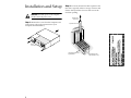
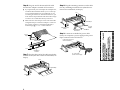
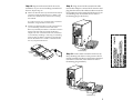
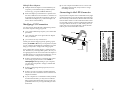
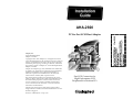
AHA-2920
PCI-to-Fast SCSI Host Adapter
Adaptec, Inc.
691 South Milpitas Blvd.
Milpitas, CA 95035
Copyright © 1995, 1996, Adaptec, Inc. All rights reserved. No
part of this publication may be reproduced, stored in a retrieval
system, or transmitted in any form or by any means, electronic,
mechanical, photocopying, recording or otherwise, without the
prior written consent of Adaptec, Inc., 691 South Milpitas Blvd.,
Milpitas, CA 95035.
Adaptec, the Adaptec logo, AHA, and EZ-SCSI are trademarks
of Adaptec, Inc. which may be registered in some jurisdictions.
Windows and Windows 95 are registered trademarks of
Microsoft Corporation used under license. All other trademarks used are owned by their respective owners.
The material in this document is for information only and is
subject to change without notice. While reasonable efforts have
been made in the preparation of this document to assure its
accuracy, Adaptec, Inc. assumes no liability resulting from
errors or omissions in this document, or from the use of the
information contained herein.
Fast SCSI Connection for
High-Performance SCSI
Peripherals for Pentium PCs
Adaptec reserves the right to make changes in the product
design without reservation and without notification to its users.
R
Printed in Singapore.
Stock No.: 510926-00, Rev. C RQ 2/96
AAAA
AAAA
AA
AA
AA
AAAA
AAAAAAAA
AAAAAAAA
AAAAAAAA
AAAAAAAA
AAAA
AA
AA
AA
AA
AA
AA
AA
AA
AA
AA
AA
AA
AA
AA
AA
AA
AA
AA
AA
AA
AA
AA
AA
AA
AA
AA
AA
AA
AA
AA
AA
AA
AA
AA
AA
AA
AA
AA
AA
AA
AA
AA
AA
AA
AA
AA
AA
AA
AA
AA
AA
AA
AA
AA
AA
AA
AA
AA
AA
AA
AA
AA
AA
AA
AA
AA
AA
AA
AA
AA
AA
AA
AA
AA
AA
AA
AA
AA
AA
AA
AA
AA
AA
AA
AA
AA
AA
AA
AA
AA
AA
AA
AA
AA
AA
AA
AA
AA
AAAA
AAAA
AAAA
AAAA
AAAA
AAAA
AA
AA AAAAAAAAAAAAAAAAAAAA
AAAA
AA
Introduction
Contents
This installation guide provides the instructions needed to install and
use your new SCSI host adapter. Once you have performed the simple
installation steps listed on pages 2 through 6, your host adapter and
SCSI devices are ready for operation.
We recommend that you keep this installation guide with your important computer documents. One of the benefits of SCSI is that you can
connect as many as seven peripherals to your host adapter. If you are
not connecting the full complement of seven peripherals during your
initial installation, when the time comes to add another peripheral,
this guide will help with that installation.
Installation and Setup
Installation Steps . . . . . . . 2 - 6
Helpful Hints
Using Your Host Adapter . 6
Modifying PCI Parameters
7
Connecting to the LED
Connector . . . . . . . . . . . . . 7
AAAA
AAAA
AA
AA
AA
AAAA
AAAAAAAA
AAAAAAAA
AAAAAAAA
AAAAAAAA
AAAA
AA
AA
AA
AA
AA
AA
AA
AA
AA
AA
AA
AA
AA
AA
AA
AA
AA
AA
AA
AA
AA
AA
AA
AA
AA
AA
AA
AA
AA
AA
AA
AA
AA
AA
AA
AA
AA
AA
AA
AA
AA
AA
AA
AA
AA
AA
AA
AA
AA
AA
AA
AA
AA
AA
AA
AA
AA
AA
AA
AA
AA
AA
AA
AA
AA
AA
AA
AA
AA
AA
AA
AA
AA
AA
AA
AA
AA
AA
AA
AA
AA
AA
AA
AA
AA
AA
AA
AA
AA
AA
AA
AA
AA
AA
AA
AA
AA
AA
AAAA
AAAA
AAAA
AAAA
AAAA
AAAA
AA
AA AAAAAAAAAAAAAAAAAAAA
AAAA
AA
Internal SCSI-2 Connector
Uses a 50-pin internal SCSI ribbon
cable to connect up to seven internal
SCSI devices.
Host Adapter BIOS
Provides booting capabilities from up
to seven SCSI hard disk drives
(under DOS 5.0 and above).
Need Assistance?
LED Connector
Connects to the computer's
LED cable to display activity
on the SCSI bus.
Troubleshooting Checklist . 8
Common Problems and
Solutions . . . . . . . . . . . . . . 8
External SCSI-2 Connector
Uses 50-pin high-density external SCSI cables
to daisy-chain up to seven external devices.
AHA-2920 Host Adapter
1
Installation and Setup
Step 2: Locate an unused PCI bus expansion slot
(this slot is typically white or ivory); unscrew and
remove the expansion slot cover that covers the
card-slot opening.
WARNING: Turn OFF power to the computer
and disconnect the power cord.
Expansion Slot
Cover Screw
Step 1: Remove the cover from the computer case.
(If necessary, refer to the instructions in your
computer documentation.)
Expansion Slot Cover
Back of
Your Computer
16-bit ISA Expansion Slot
(typically black)
2
PCI Expansion Slots
(typically white or ivory)
AAAA
AAAA
AA
AA
AA
AAAA
AAAAAAAA
AAAAAAAA
AAAAAAAA
AAAAAAAA
AAAA
AA
AA
AA
AA
AA
AA
AA
AA
AA
AA
AA
AA
AA
AA
AA
AA
AA
AA
AA
AA
AA
AA
AA
AA
AA
AA
AA
AA
AA
AA
AA
AA
AA
AA
AA
AA
AA
AA
AA
AA
AA
AA
AA
AA
AA
AA
AA
AA
AA
AA
AA
AA
AA
AA
AA
AA
AA
AA
AA
AA
AA
AA
AA
AA
AA
AA
AA
AA
AA
AA
AA
AA
AA
AA
AA
AA
AA
AA
AA
AA
AA
AA
AA
AA
AA
AA
AA
AA
AA
AA
AA
AA
AA
AA
AA
AA
AA
AA
AAAA
AAAA
AAAA
AAAA
AAAA
AAAA
AA
AA AAAAAAAAAAAAAAAAAAAA
AAAA
AA
Step 3: Insert the host adapter in the slot; press
Step 4: Prepare each internal SCSI device for
down firmly so that the bus contacts are securely
seated in the slot. Secure it with the screw you
removed in Step 2.
installation. If you are installing External SCSI
devices only, skip to Step 10.
■
Expansion Slot
Cover Screw
Make sure all SCSI devices (internal and external) are
assigned a unique SCSI ID from 0 to 6. Refer to the
device’s documentation for instructions on setting
the SCSI ID.
If you plan to boot your computer from a SCSI hard
disk drive, assign SCSI ID 6 to this drive.
Host Adapter Bracket
■
Bus Contacts
Install (or enable) terminators on the internal device
you are attaching to the end of the cable. Remove (or
disable) terminators on all devices that you are installing between the end of the cable and host adapter.
On most internal SCSI devices the termination setting
is controlled by setting a jumper or a switch, or by
physically removing or installing a resistor module(s).
Refer to the device’s documentation to determine
how to enable or disable termination on your particular device.
PCI Expansion Slot
(typically white or ivory)
Termination
Enabled
Termination
Disabled
Step 5: Install and mount each internal SCSI
device in an available drive bay inside your
computer. (Refer to your computer and device
documentation for instructions.)
3
AAAA
AAAA
AA
AA
AA
AAAA
AAAAAAAA
AAAAAAAA
AAAAAAAA
AAAAAAAA
AAAA
AA
AA
AA
AA
AA
AA
AA
AA
AA
AA
AA
AA
AA
AA
AA
AA
AA
AA
AA
AA
AA
AA
AA
AA
AA
AA
AA
AA
AA
AA
AA
AA
AA
AA
AA
AA
AA
AA
AA
AA
AA
AA
AA
AA
AA
AA
AA
AA
AA
AA
AA
AA
AA
AA
AA
AA
AA
AA
AA
AA
AA
AA
AA
AA
AA
AA
AA
AA
AA
AA
AA
AA
AA
AA
AA
AA
AA
AA
AA
AA
AA
AA
AA
AA
AA
AA
AA
AA
AA
AA
AA
AA
AA
AA
AA
AA
AA
AA
AAAA
AAAA
AAAA
AAAA
AAAA
AAAA
AA
AA AAAAAAAAAAAAAAAAAAAA
AAAA
AA
Step 6: Plug one end of the internal SCSI cable
Step 8: Plug the remaining connectors on the cable
into the host adapter’s internal SCSI connector.
into any remaining internal devices (these devices
must not be terminated; see Step 4).
■
■
If you purchased your host adapter in an Adaptec kit,
an internal SCSI cable that allows you to connect up
to two internal SCSI devices is included. If you are
connecting more than two internal SCSI devices, you
must obtain a 50-pin internal SCSI cable with enough
connectors to accommodate all of your devices.
Pin 1
Make sure the colored stripe on one side of the cable
is aligned with pin-1 of the host adapter’s connector.
Pin-1 of the connector is usually designated by a
small triangle (▲), or a “1” on the connector.
Colored Stripe
To Host
Adapter
2nd Internal SCSI
Device
To 1st Internal
SCSI Device
Step 9: Connect an available DC power cable
Colored
Stripe
(from your computer’s power supply) to the power
input connector on the SCSI device.
50-pin SCSI
Ribbon Cable
Power Input Connector on
the Back of the Drive
Pin 1
Internal SCSI
Connector
Step 7: Plug the other end of the cable into the last
internal device (this device must be terminated; see
Step 4).
Pin 1
Colored Stripe
Internal SCSI
Device
4
DC Power Cable
(from the Power Supply)
AAAA
AAAA
AA
AA
AA
AAAA
AAAAAAAA
AAAAAAAA
AAAAAAAA
AAAAAAAA
AAAA
AA
AA
AA
AA
AA
AA
AA
AA
AA
AA
AA
AA
AA
AA
AA
AA
AA
AA
AA
AA
AA
AA
AA
AA
AA
AA
AA
AA
AA
AA
AA
AA
AA
AA
AA
AA
AA
AA
AA
AA
AA
AA
AA
AA
AA
AA
AA
AA
AA
AA
AA
AA
AA
AA
AA
AA
AA
AA
AA
AA
AA
AA
AA
AA
AA
AA
AA
AA
AA
AA
AA
AA
AA
AA
AA
AA
AA
AA
AA
AA
AA
AA
AA
AA
AA
AA
AA
AA
AA
AA
AA
AA
AA
AA
AA
AA
AA
AA
AAAA
AAAA
AAAA
AAAA
AAAA
AAAA
AA
AA AAAAAAAAAAAAAAAAAAAA
AAAA
AA
Step 10: Prepare each external SCSI device for
Step 11: Plug one end of the external SCSI cable
installation. If you are not installing external SCSI
devices, skip to Step 13.
into the host adapter’s external SCSI connector and
plug the other end of the cable into either one of the
SCSI connectors on the external SCSI device. (If you
are installing only one external device, attach a
terminating plug to the device)
■
Make sure all SCSI devices (external and internal) are
assigned a unique SCSI ID from 0 to 6. Refer to the
device’s documentation for instructions on setting
the SCSI ID.
If you plan to boot your computer from a SCSI hard
disk drive, assign SCSI ID 6 to this drive.
Install (or enable) terminators on the external device
you are attaching at the end of the SCSI chain.
Remove (or disable) terminators on all devices that lie
between the end of the SCSI chain and the host
adapter. On most external SCSI devices, termination
is controlled by installing or removing a terminating
plug (see Step 11). Refer to the device’s documentation to determine how to enable or disable termination on your particular device.
3
Terminating Plug
Termination
Enabled
Step 12: Connect other external SCSI devices by
Termination
Disabled
Termination
Disabled
daisy-chaining each device to the previous device
until all external SCSI devices have been connected.
(The device at the end of the chain must have a
terminating plug installed.)
3
2
■
4
Terminating Plug
5
AAAA
AAAA
AA
AA
AA
AAAA
AAAAAAAA
AAAAAAAA
AAAAAAAA
AAAAAAAA
AAAA
AA
AA
AA
AA
AA
AA
AA
AA
AA
AA
AA
AA
AA
AA
AA
AA
AA
AA
AA
AA
AA
AA
AA
AA
AA
AA
AA
AA
AA
AA
AA
AA
AA
AA
AA
AA
AA
AA
AA
AA
AA
AA
AA
AA
AA
AA
AA
AA
AA
AA
AA
AA
AA
AA
AA
AA
AA
AA
AA
AA
AA
AA
AA
AA
AA
AA
AA
AA
AA
AA
AA
AA
AA
AA
AA
AA
AA
AA
AA
AA
AA
AA
AA
AA
AA
AA
AA
AA
AA
AA
AA
AA
AA
AA
AA
AA
AA
AA
AAAA
AAAA
AAAA
AAAA
AAAA
AAAA
AA
AA AAAAAAAAAAAAAAAAAAAA
AAAA
AA
Step 13: Reinstall your computer cover and
connect all power cables; turn on your computer.
Step 14: Install the appropriate device driver for
your operating system.
■
DOS and Windows® 3.x: Drivers for DOS and Windows 3.x must be loaded from the Adaptec EZ-SCSI®
software (use EZ-SCSI 4.x and above only). If you purchased your host adapter in an Adaptec kit, EZ-SCSI is
included in the kit. Run EZ-SCSI to install the drivers
automatically (see the EZ-SCSI User’s Guide). If you
need to purchase EZ-SCSI, contact Adaptec.
EZ-SCSI also contains applications, such as a Photo CD
Viewer and SCSI tape backup program. See Adaptec
EZ-SCSI for requirements and installation procedures.
■
■
Windows® 95: Windows 95 has embedded driver
support for your host adapter and lists it as a Future
Domain TMC-3260. When you start Windows 95, the
host adapter is detected in your system and the
embedded driver is automatically installed.
Other Operating Systems: The host adapter supports
OS/2, Windows NT, SCO UNIX, and Novell NetWare
and UnixWare operating systems. Note the following
table to obtain the drivers for your host adapter.
OS
OS/2 Warp 3.0
NetWare
v3.12—4.1
Windows NT
v3.1
Windows NT
v3.5—3.51
SCO UNIX
R3.2 v4.2, v5.0
UnixWare v2.02
and above
Driver Location
On the 3600 Manager
Set diskette1
On the 3600 Manager
Set diskette1
On the 3600 Manager
Set diskette1
Adapter Name/Selection
Adaptec AHA-2905/2920
Helpful Hints
Using Your Host Adapter
Once your host adapter is installed, you can refer to this
section for useful information on using your host adapter.
■
Except for SCSI hard disk and CD-ROM drives, many
SCSI devices require you to install the manufacturer’s
proprietary driver for operation. (See your device’s
documentation.)
■
For all SCSI devices connected to the host adapter,
make sure to use high-quality SCSI cables to ensure
reliable data transfer.
■
When one or more Fast SCSI devices are connected to
the host adapter, the combined length of all cables
(internal and external) must not exceed 3 meters (9.8
ft.) to ensure reliable operation. If no Fast SCSI
devices are connected, the combined length of all
cables must not exceed 6 meters (19.7 ft). See your
device’s documentation to determine if it is a Fast
SCSI device.
Hard Disk Drives
■
Adaptec AHA-2905/2920
Adaptec AHA-2905/2920
If you connected a new hard disk drive to your host
adapter, you must partition and logically format the
drive. For DOS, Windows (3.x and 95), use the DOS
Fdisk and Format commands (see your computer and
DOS documentation). For other operating systems,
see your operating system documentation.
Future Domain TMC-3260
Embedded in OS
Access driver on
Adaptec BBS
Adaptec AHA-2905/2920
Future Domain TMC-3260
Embedded in OS
1 Read the readme.txt file in the particular subdirectory on the 3600 Manager Set
■
If you are booting from a SCSI hard disk drive, make
sure the Hard Disk (or Drives) setting in your computer’s CMOS setup program is set to None or No
Drives Installed, as is required for SCSI hard disk
drives. (See your computer documentation.)
■
If both SCSI and non-SCSI (e.g., IDE) disk drives are
installed, then the non-SCSI disk drive is always the
boot device.
diskette for installation instructions.
If you need to purchase the 3600 Manager Set, contact
Adaptec.
Congratulations! Installation of your host
adapter is complete. For useful information on
using your host adapter, refer to Helpful Hints on
this page. If you need further help, refer to Need
Assistance? on page 8.
6
Every hard disk must be physically low-level formatted, partitioned, and logically formatted before it can
be used to store data. SCSI hard disks are physically
formatted at the factory and do not need to be physically formatted again.
AAAA
AAAA
AA
AA
AA
AAAA
AAAAAAAA
AAAAAAAA
AAAAAAAA
AAAAAAAA
AAAA
AA
AA
AA
AA
AA
AA
AA
AA
AA
AA
AA
AA
AA
AA
AA
AA
AA
AA
AA
AA
AA
AA
AA
AA
AA
AA
AA
AA
AA
AA
AA
AA
AA
AA
AA
AA
AA
AA
AA
AA
AA
AA
AA
AA
AA
AA
AA
AA
AA
AA
AA
AA
AA
AA
AA
AA
AA
AA
AA
AA
AA
AA
AA
AA
AA
AA
AA
AA
AA
AA
AA
AA
AA
AA
AA
AA
AA
AA
AA
AA
AA
AA
AA
AA
AA
AA
AA
AA
AA
AA
AA
AA
AA
AA
AA
AA
AA
AA
AAAA
AAAA
AAAA
AAAA
AAAA
AAAA
AA
AA AAAAAAAAAAAAAAAAAAAA
AAAA
AA
Multiple Host Adapters
■
Multiple SCSI host adapters can be installed in your
computer; you are limited only by available system
resources (e.g., I/O port and BIOS addresses).
■
Each host adapter you install forms a separate SCSI
bus with a different set of SCSI devices. SCSI IDs can
be reused as long as the ID is assigned to a device on
a different host adapter (e.g., each host adapter can
have a device with SCSI ID 0).
Modifying PCI Parameters
You may need to change the PCI configuration parameters in the computer’s setup program if
■
your system CMOS setup requires you to enable PCI
parameters.
■
your computer does not recognize the host adapter
after you install it.
■
you cannot access any of the devices.
■
In some computers the BIOS reserves a set of available IRQs for PCI boards, and you have to assign
these IRQs manually.
Connecting to the LED Connector
(Optional) Most computers have an LED disk activity light
on the front panel. If you want the LED to light whenever
there is activity on the SCSI bus, then disconnect the cable
from the LED connector on the motherboard and connect
it to the LED connector on the host adapter (the LED will
no longer indicate non-SCSI, i.e., IDE, activity). On computers with a two-position LED cable, connect the LED
cable to pins 1 and 2 of the LED connector.
Pin 1
Usually you start the setup program by pressing a specified key like Delete or F1 when your computer boots (refer
to your computer documentation). Listed below are some
things you may need to change in the setup program.
Some configuration options apply to a specific PCI bus
slot. Therefore, if you change these options, be sure you
are applying them to the slot in which the host adapter is
installed. Read your computer documentation if you are
not sure which slot corresponds to each number.
■
If there is an Interrupt Type or Interrupt Line option
in the setup program, be sure to select Int-A or
Interrupt Type = A. Depending on your computer,
you may also be required to change a motherboard
jumper setting.
■
If there is a Triggering Interrupt option, be sure to
select Level.
■
If there is an option to enable or disable individual
PCI slots, be sure to enable the slot in which the host
adapter is installed.
■
If your computer has a combination of ISA (or EISA)
boards and PCI boards, you may need to mark the
IRQs used by ISA/EISA boards as Used so the computer BIOS will not try to assign these IRQs to other
PCI boards.
AAAA
AAAA
AA
AA
AA
AAAA
AAAAAAAA
AAAAAAAA
AAAAAAAA
AAAAAAAA
AAAA
AA
AA
AA
AA
AA
AA
AA
AA
AA
AA
AA
AA
AA
AA
AA
AA
AA
AA
AA
AA
AA
AA
AA
AA
AA
AA
AA
AA
AA
AA
AA
AA
AA
AA
AA
AA
AA
AA
AA
AA
AA
AA
AA
AA
AA
AA
AA
AA
AA
AA
AA
AA
AA
AA
AA
AA
AA
AA
AA
AA
AA
AA
AA
AA
AA
AA
AA
AA
AA
AA
AA
AA
AA
AA
AA
AA
AA
AA
AA
AA
AA
AA
AA
AA
AA
AA
AA
AA
AA
AA
AA
AA
AA
AA
AA
AA
AA
AA
AAAA
AAAA
AAAA
AAAA
AAAA
AAAA
AA
AA AAAAAAAAAAAAAAAAAAAA
AAAA
AA
LED Cable
1
LED Connector
7
Need Assistance?
■
Troubleshooting Checklist
Most problems that occur with your host adapter result
from errors in preparing and connecting devices on the
SCSI bus. If you have problems when using your host
adapter, check these items first.
■
Are all SCSI devices powered?
■
Are all SCSI bus cables and power cables properly
connected?
■
Is the host adapter firmly seated and secured in a PCI
expansion slot?
■
Is pin-1 orientation maintained throughout the SCSI
bus? (See Step 6 on page 4.)
■
Do the host adapter and all devices on the SCSI bus
have unique SCSI IDs? (See Step 4 on page 3, and
Step 10 on page 5.)
■
Are all devices on the SCSI bus terminated properly?
(See Step 4 on page 3, and Step 10 on page 5.)
■
Does your system CMOS setup require you to enable
PCI bus parameters? If so, see your computer’s documentation. Check that IRQ channel assignment,
board, and BIOS settings have been made.
If you still have problems after checking the above items,
continue with the following section.
Common Problems and Solutions
I installed the host adapter and my SCSI disk drive, but my computer
will not boot from the SCSI disk drive.
If both SCSI and non-SCSI (e.g., IDE) disk drives are
installed, then the non-SCSI disk drive is always the boot
device. If your system has only SCSI disk drives:
■
Make sure the Hard Disk (or Drives) setting in your
computer’s setup program is set to None or No
Drives Installed, as is required for SCSI hard disk
drives.
■
Make sure the SCSI boot drive is set to SCSI ID 6.
8
If you have an ISA-based SCSI host adapter installed
with a connected SCSI hard drive, this SCSI hard
drive will be your boot device, since ISA host adapters have higher priority in the system than PCI host
adapters.
I receive the No SCSI devices found. Check cables and power error
message.
An unexpected time-out occurred.
■
Check that the terminator is securely attached to the
SCSI connector on the hard drive. Check that the SCSI
cable is securely connected to the SCSI connectors on
both host adapter and the SCSI device. Then reboot
the computer.
■
If the above step does not work, turn OFF the computer, disconnect the SCSI cable from the host
adapter and then restart the computer. If the computer successfully restarts, the SCSI cable, terminator,
or hard drive may be defective.
When the Adaptec BIOS header message appears, it hangs my system.
Make sure the SCSI hard drives are properly terminated.
One of the SCSI devices on my computer does not allow me to
disable termination. How can I install it on the SCSI bus?
If it is an external SCSI device, install the device as the
last device of the external daisy chain. If it is an internal
SCSI device, install the device at the end of the internal
SCSI cable.
The system works erratically. It hangs or the host adapter sometimes
cannot find the drives.
Check cable length and integrity. If one or more Fast SCSI
devices are installed, the total length of all cables (internal and external) connected to the host adapter should
not exceed 3 meters (9.8 ft.). If no Fast SCSI devices are
connected, the total length of all cables should not exceed
6 meters (19.7 ft.).
AAAA
AAAA
AA
AA
AA
AAAA
AAAAAAAA
AAAAAAAA
AAAAAAAA
AAAAAAAA
AAAA
AA
AA
AA
AA
AA
AA
AA
AA
AA
AA
AA
AA
AA
AA
AA
AA
AA
AA
AA
AA
AA
AA
AA
AA
AA
AA
AA
AA
AA
AA
AA
AA
AA
AA
AA
AA
AA
AA
AA
AA
AA
AA
AA
AA
AA
AA
AA
AA
AA
AA
AA
AA
AA
AA
AA
AA
AA
AA
AA
AA
AA
AA
AA
AA
AA
AA
AA
AA
AA
AA
AA
AA
AA
AA
AA
AA
AA
AA
AA
AA
AA
AA
AA
AA
AA
AA
AA
AA
AA
AA
AA
AA
AA
AA
AA
AA
AA
AA
AAAA
AAAA
AAAA
AAAA
AAAA
AAAA
AA
AA AAAAAAAAAAAAAAAAAAAA
AAAA
AA
FCC Compliance Statement
This equipment has been tested and found to comply with the limits for a
Class B digital device, pursuant to Part 15 of the FCC rules. These limits
are designed to provide reasonable protection against harmful interference in residential installations. This equipment generates, uses, and can
radiate radio frequency energy, and if not installed and used in accordance with the instructions, may cause harmful interference to radio communications. However, there is no guarantee that interference will not
occur in a particular installation.
If this equipment does cause interference to radio or television equipment
reception, which can be determined by turning the equipment off and on,
the user is encouraged to try to correct the interference by one or more of
the following measures:
•
•
•
Reorient or relocate the receiving antenna
Move the equipment away from the receiver
Plug the equipment into an outlet on a circuit different from that to
which the receiver is powered
• If necessary, the user should consult the dealer or an experienced
radio/television technician for additional suggestions
CAUTION: Only equipment certified to comply with Class B (computer
input/output devices, terminals, printers, etc.) should be attached to this
equipment, and must have shielded interface cables.
AAAA
AAAA
AA
AA
AA
AAAA
AAAAAAAA
AAAAAAAA
AAAAAAAA
AAAAAAAA
AAAA
AA
AA
AA
AA
AA
AA
AA
AA
AA
AA
AA
AA
AA
AA
AA
AA
AA
AA
AA
AA
AA
AA
AA
AA
AA
AA
AA
AA
AA
AA
AA
AA
AA
AA
AA
AA
AA
AA
AA
AA
AA
AA
AA
AA
AA
AA
AA
AA
AA
AA
AA
AA
AA
AA
AA
AA
AA
AA
AA
AA
AA
AA
AA
AA
AA
AA
AA
AA
AA
AA
AA
AA
AA
AA
AA
AA
AA
AA
AA
AA
AA
AA
AA
AA
AA
AA
AA
AA
AA
AA
AA
AA
AA
AA
AA
AA
AA
AA
AAAA
AAAA
AAAA
AAAA
AAAA
AAAA
AA
AA AAAAAAAAAAAAAAAAAAAA
AAAA
AA
Finally, any changes or modifications to the equipment by the user not
expressly approved by the grantee or manufacturer could void the user's
authority to operate such equipment.
Each host adapter is equipped with an FCC compliance label which
shows only the FCC Identification number. The full text of the associated
label follows:
This device complies with part 15 of the FCC rules. Operation is subject to
the following two conditions: (1) this device may not cause harmful interference and (2) this device must accept any interference received, including interference that may cause undesired operation.
European Community Mark
CE mark is rated for the adapter as follows:
•
•
CISPR 22 Radiated Emissions (EN 550022)
EN50082-1 Generic immunity standard for the following:
– 801-2 ESD Immunity
– 801-3 Radiated Immunity
– 801-4 Fast Burst Immunity
9
AHA-2920
PCI-to-Fast SCSI Host Adapter
Adaptec, Inc.
691 South Milpitas Blvd.
Milpitas, CA 95035
Copyright © 1995, 1996, Adaptec, Inc. All rights reserved. No
part of this publication may be reproduced, stored in a retrieval
system, or transmitted in any form or by any means, electronic,
mechanical, photocopying, recording or otherwise, without the
prior written consent of Adaptec, Inc., 691 South Milpitas Blvd.,
Milpitas, CA 95035.
Adaptec, the Adaptec logo, AHA, and EZ-SCSI are trademarks
of Adaptec, Inc. which may be registered in some jurisdictions.
Windows and Windows 95 are registered trademarks of
Microsoft Corporation used under license. All other trademarks used are owned by their respective owners.
The material in this document is for information only and is
subject to change without notice. While reasonable efforts have
been made in the preparation of this document to assure its
accuracy, Adaptec, Inc. assumes no liability resulting from
errors or omissions in this document, or from the use of the
information contained herein.
Fast SCSI Connection for
High-Performance SCSI
Peripherals for Pentium PCs
Adaptec reserves the right to make changes in the product
design without reservation and without notification to its users.
R
Printed in Singapore.
Stock No.: 510926-00, Rev. C RQ 2/96
AAAA
AAAA
AA
AA
AA
AAAA
AAAAAAAA
AAAAAAAA
AAAAAAAA
AAAAAAAA
AAAA
AA
AA
AA
AA
AA
AA
AA
AA
AA
AA
AA
AA
AA
AA
AA
AA
AA
AA
AA
AA
AA
AA
AA
AA
AA
AA
AA
AA
AA
AA
AA
AA
AA
AA
AA
AA
AA
AA
AA
AA
AA
AA
AA
AA
AA
AA
AA
AA
AA
AA
AA
AA
AA
AA
AA
AA
AA
AA
AA
AA
AA
AA
AA
AA
AA
AA
AA
AA
AA
AA
AA
AA
AA
AA
AA
AA
AA
AA
AA
AA
AA
AA
AA
AA
AA
AA
AA
AA
AA
AA
AA
AA
AA
AA
AA
AA
AA
AA
AAAA
AAAA
AAAA
AAAA
AAAA
AAAA
AA
AA AAAAAAAAAAAAAAAAAAAA
AAAA
AA