1
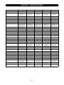
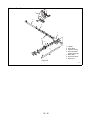
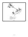
TABLE OF CONTENTS
Section 1 - Introduction . . . . . . . . . . . . . . . . .
1.1 The Manual . . . . . . . . . . . . . . . . . . . . . . .
1.2 Service and Replacement Parts . . . . . . .
1.3 Product Registration . . . . . . . . . . . . . . . .
1.4 Unauthorized Replacement Parts . . . . . .
1.5 Disclaimer . . . . . . . . . . . . . . . . . . . . . . . .
1.6 Technical Service Communications . . . . .
1.3
1.3
1.3
1.3
1.3
1.3
1.3
Section 5 - HandleBars & Controls . . . . . . . .5.23
5.1 Upper Handlebar Panel & Key Switch . . .5.23
5.2 Lower Handlebar . . . . . . . . . . . . . . . . . . .5.23
5.3 Attachment Clutch Handle . . . . . . . . . . . .5.23
5.4 Attachment Clutch Adjustment. . . . . . . . .5.23
5.5 Wheel Drive Clutch Lever & Traction Rod 5.23
5.6 Clutch Yoke and Fork . . . . . . . . . . . . . . . .5.24
Section 2 - Safety . . . . . . . . . . . . . . . . . . . . . .
2.1 Safety Alerts . . . . . . . . . . . . . . . . . . . . . .
2.2 Signal Words . . . . . . . . . . . . . . . . . . . . . .
2.3 Notations . . . . . . . . . . . . . . . . . . . . . . . . .
2.4 Practices and Laws . . . . . . . . . . . . . . . . .
2.5 Required Operator Training . . . . . . . . . . .
2.6 Preparation . . . . . . . . . . . . . . . . . . . . . . .
2.7 Service Position . . . . . . . . . . . . . . . . . . . .
2.8 Cleaning and Storage . . . . . . . . . . . . . . .
2.9 Safety Rules. . . . . . . . . . . . . . . . . . . . . . .
2.4
2.4
2.4
2.4
2.4
2.4
2.4
2.4
2.4
2.5
Section 6 - Engine . . . . . . . . . . . . . . . . . . . . . .6.25
6.1 Engine Troubleshooting . . . . . . . . . . . . . .6.25
6.2 Removing the Engine. . . . . . . . . . . . . . . .6.26
6.3 Installing The Engine . . . . . . . . . . . . . . . .6.26
Section 7 - Reduction Drive . . . . . . . . . . . . . .7.27
7.1 Differential, Lockout, And Axle . . . . . . . . .7.27
7.2 Axle Bearings. . . . . . . . . . . . . . . . . . . . . .7.27
7.3 Pinion, Shaft, And Sprocket . . . . . . . . . . .7.27
7.4 Reduction Shaft . . . . . . . . . . . . . . . . . . . .7.27
7.5 Hex Shaft . . . . . . . . . . . . . . . . . . . . . . . . .7.28
7.6 Drive Chains . . . . . . . . . . . . . . . . . . . . . .7.28
7.7 Drive Chain Adjustment . . . . . . . . . . . . . .7.28
Section 3 - Specifications . . . . . . . . . . . . . . . 3.7
Section 4 - General Maintenance &
Section 8 - Friction Wheel Drive . . . . . . . . . .8.29
8.1 Friction Wheel . . . . . . . . . . . . . . . . . . . . .8.29
8.2 Friction Wheel Carrier . . . . . . . . . . . . . . .8.29
8.3 Drive Plate Spindle . . . . . . . . . . . . . . . . .8.29
Adjustments. . . . . . . . . . . . . . . . . . . . . . . .4.15
4.1 Controls and Features . . . . . . . . . . . . . . . 4.15
4.2 Service Positions . . . . . . . . . . . . . . . . . . . 4.16
4.3 Filling The Fuel Tank . . . . . . . . . . . . . . . . 4.16
4.4 Fuel Shut-Off Valve . . . . . . . . . . . . . . . . . 4.17
4.5 General Lubrication . . . . . . . . . . . . . . . . . 4.17
4.6 Auger Gearcase. . . . . . . . . . . . . . . . . . . .4.18
4.7 Engine . . . . . . . . . . . . . . . . . . . . . . . . . . . 4.18
4.8 Traction Drive Belt . . . . . . . . . . . . . . . . . . 4.18
4.9 Attachment Drive Belt . . . . . . . . . . . . . . . 4.19
4.10 Shear Bolts . . . . . . . . . . . . . . . . . . . . . . 4.19
4.11 Tire Pressure . . . . . . . . . . . . . . . . . . . . . 4.20
4.12 Adjustments . . . . . . . . . . . . . . . . . . . . . . 4.20
Section 9 - Auger/Impeller . . . . . . . . . . . . . . .9.31
9.1 Auger/Impeller Removal. . . . . . . . . . . . . .9.31
9.2 Scraper Blade . . . . . . . . . . . . . . . . . . . . .9.31
9.3 Shear Bolts . . . . . . . . . . . . . . . . . . . . . . .9.31
9.4 Discharge Chute . . . . . . . . . . . . . . . . . . .9.32
9.5 Deflector. . . . . . . . . . . . . . . . . . . . . . . . . .9.32
9.6 Runners . . . . . . . . . . . . . . . . . . . . . . . . . .9.32
Section 10 - Gear Case . . . . . . . . . . . . . . . . . 10.34
10.1 Cast Iron Gear Case (Worm Gear) . . . 10.34
10.2 Aluminum Gear Case. . . . . . . . . . . . . . 10.34
2
SECTION 1 - INTRODUCTION
1.1 THE MANUAL
1.3 PRODUCT REGISTRATION
It is the purpose of this manual to provide complete
instructions for service, maintenance, disassembly,
repair, and installation of the mechanical components
for the 924 Snow-Thro.
A warranty registration card must be filled out, signed,
and returned at the time of purchase. This card
activates the warranty. Claims meeting requirements
during limited warranty period will be honored.
Dealer trained service personnel should use this
manual as a supplement to and reminder of the training
sessions conducted by the company.
1.4 UNAUTHORIZED REPLACEMENT
PARTS
Use only Ariens replacement parts. The replacement
of any part on this vehicle with anything other than a
Ariens authorized replacement part may adversely
affect the performance, durability, or safety of this unit
and may void the warranty. Ariens disclaims liability for
any claims or damages, whether warranty, property
damage, personal injury, or death arising out of the use
of unauthorized replacement parts.
Read all information for servicing a part of system
before repair work is started to avoid needless
disassembly.
Operation
Before operation of the unit, carefully and completely
read manuals supplied with the unit. The contents will
provide you with an understanding of safety
instructions and controls during normal operation and
maintenance.
1.5 DISCLAIMER
Directional Reference
Ariens reserves the right to discontinue, make changes
to, and add improvements upon its products at any time
without public notice or obligation. The descriptions
and specifications contained in this manual were in
effect at printing. Equipment described within this
manual may be optional. Some illustrations may not be
applicable to your unit.
All reference to left, right, front, or rear are given from
the operator in the operator position and facing the
direction of forward travel.
1.6 TECHNICAL SERVICE
COMMUNICATIONS
Safety Messages
For your safety and the safety of others always read,
understand, and follow all DANGER, WARNING, and
CAUTION messages found in manuals and on safety
decals.
1.2 SERVICE AND REPLACEMENT PARTS
When ordering publications, replacement parts, or
making service inquiries, know the Model and Serial
numbers of your unit and engine.
Numbers are located on the product registration form in
the unit literature package. They are printed on a serial
number label, located on the frame of your unit.
Ariens Technical Service communicates information to
the field using Service Letters, Service Bulletins,
Product Notices, and Campaigns. Each communication
signifies a type of information and priority. The dealer is
responsible to carry out the directive provided in the
communication. The types of communication are:
Service Letter - General technical information for the
dealer. Technical information on how to service the
product and product improvements.
Service Bulletin - Notification to update products to
resolve certain issues or a notification of a policy
change.
Product Notices - Notification of limited product
located in a certain region. This is a limited distribution
to only those who received the product involved.
Campaigns - Notification of a safety related issue. All
product must be updated and are tracked by the factory
until all units are corrected.
Figure 1
1-3
SECTION 2 - SAFETY
2.6 PREPARATION
2.1 SAFETY ALERTS
Look for these symbols to point out
important safety precautions. They
mean:
Before starting any removal of parts, proper
preparation is very important for efficient work. A clean
work area at the start of each job will allow you to
perform service repairs easily and quickly.
Attention!
Personal Safety Is Involved!
Become Alert!
Obey The Message!
To reduce the incidence of misplaced tools or parts,
place removed components with all attaching hardware
in the disassembly order on a clean work surface.
Organization is a key part of proper reassembly.
Tools, instruments, and parts needed for the job should
be gathered before work is started. Interrupting a job to
locate tools or parts is a needless delay. A list of
required special tools has been included in this
manual.
2.2 SIGNAL WORDS
The safety alert symbol is used in decals on the unit
and with proper operation procedures in this manual.
They alert you to the existence and relative degree of
hazards.
2.7 SERVICE POSITION
Understand the safety message. It contains important
information about personal safety on or near the unit.
WARNING: ALWAYS block wheels and know
that jack stands or blocks used are stable,
strong, or secure and will hold the weight of
the unit during maintenance.
DANGER: IMMINENTLY HAZARDOUS
SITUATION! If not avoided, WILL RESULT in
death or serious injury.
To ensure the unit is positioned in the proper service
position place unit on a flat level surface. ALWAYS stop
engine. Assure unit is secure and will not tip over. Strap
and clamp onto lift if used.
WARNING: POTENTIALLY HAZARDOUS
SITUATION! If not avoided, COULD RESULT
in death or serious injury.
For additional requirements see section on service
position.
CAUTION: POTENTIALLY HAZARDOUS
SITUATION! If not avoided, MAY RESULT in
minor or moderate injury. It may also be used
to alert against unsafe practices.
2.8 CLEANING AND STORAGE
WARNING: AVOID SHARP EDGES which
can cut. Movement of parts can cut off fingers
or a hand. Wear gloves, and use extreme
caution when servicing.
2.3 NOTATIONS
NOTE: General reference information for proper operation and maintenance practices.
IMPORTANT: Specific procedures or information
required to prevent damage to unit or attachment.
2.4 PRACTICES AND LAWS
Practice usual and customary safe working
precautions, for the benefit of yourself and others.
Understand and follow all safety messages. Be alert to
unsafe conditions and the possibility of minor,
moderate, or serious injury or death. Learn applicable
rules and laws in your area.
IMPORTANT: Never spray unit with water or store unit
outdoors to help prevent sealed bearing rust or
corrosion. Water can seep into sealed bearings and
reduce component life. Bearings are sealed against dirt
and debris only.
A unit that is excessively dirty should be cleaned before
work starts. Cleaning will occasionally uncover trouble
sources. Dirt and abrasive dust reduce the efficient
work life of parts and can lead to costly replacement.
When taking unit out of extended storage:
2.5 REQUIRED OPERATOR TRAINING
Original purchaser of this unit was instructed by the
seller on safe and proper operation. If unit is to be used
by someone other than original purchaser; loaned,
rented or sold, ALWAYS provide this manual and any
needed safety training before operation.
2-4
1. Check for any damage or loose parts. Repair,
replace, or tighten hardware before operation.
2. If a preservative fluid was used in fuel tank, drain
and discard. Fill fuel tank with fresh new fuel.
Hazardous Slopes
2.9 SAFETY RULES
DO NOT operate on steep slopes. Avoid operating on
slopes. When you must operate on a slope, travel up
and down the slope. Never operate cross a slope.
Never operate on a slope greater than 10 degrees.
Walk Around Inspection
Complete a walk around inspection of unit and work
area to understand:
• Work area.
Child Safety
• Your unit.
NEVER allow children to operate or play on or near
unit. Be alert and shut off unit if children enter area.
• All safety decals.
Work Area
Personal Safety
ALWAYS check overhead and side clearances carefully
before operation. ALWAYS be aware of traffic when
operating along streets or curbs.
Read and obey all warning, caution, and instructions
on the unit and in provided manuals.
• Only trained adults may operate unit.
ALWAYS keep hands and feet within the limits of the
unit.
• Training includes actual operation.
Keep children, people, and animals away. Keep
children out of work area and under watchful care of a
responsible adult.
• Be alert! Conditions can change.
• Clearly understand instructions.
Keep area of operation clear of all toys, pets, and
debris. Stay alert for hidden hazards.
NEVER operate unit after or during the use of
medication, drugs or alcohol. Safe operation requires
your complete and unimpaired attention at all times.
DO NOT run engine in an enclosed area. Always
provide good ventilation.
NEVER allow anyone to operate the unit when their
alertness or coordination is impaired.
DO NOT operate unit without wearing adequate outer
garments. Wear adequate safety gear and protective
gloves. Wear proper footwear to improve footing on
slippery surfaces.
Unit
ALWAYS keep protective structures, guards, and
panels in good repair, in place and securely fastened.
NEVER modify or remove safety devices.
Protect eyes, face, and head from objects that may be
thrown from unit. Wear appropriate hearing protection.
Operation
Avoid Sharp Edges. Sharp edges can cut. Moving
parts can cut or amputate fingers or a hand. Wear
gloves to service unit when handling sharp edges.
Understand:
• How to operate all controls
• The functions of all controls
ALWAYS keep hands away from any pinch points.
• How to STOP in an Emergency
ALWAYS keep hands and feet away from all moving
parts during operation. Moving parts can cut off body
parts.
• Speed ranges
Before starting engine, disengage auxiliary power.
Always back up slowly. Always look down and behind
before and while backing.
DO NOT touch unit parts which might be hot from
operation. Allow parts to cool before attempting to
maintain, adjust, or service.
Never leave a running unit unattended. ALWAYS shut
off auxiliary power, lower throttle setting, and stop
engine before leaving unit. ALWAYS remove key to
prevent unauthorized use.
Controls
Come to a complete stop before reversing.
Never jerk the control levers. Always use a steady even
action to achieve smooth control.
ALWAYS operate unit in good visibility and light.
Fuel is highly flammable and its vapors can explode.
Use ONLY approved RED fuel containers.
NO Smoking!
NO Sparks!
NO Flames!
Allow engine to cool before servicing.
NEVER fill fuel tank when engine is running, hot, or
unit is indoors.
Always be aware of obstructions that may cause injury
to operator or damage to the unit.
Keep alert with eyes fixed in direction of travel.
Maintenance
Abnormal Vibrations are a warning of trouble. Striking a
foreign object can damage unit. Stop unit and engine.
Wait for all moving parts to stop. Remove wire from
spark plug. Inspect unit and make any necessary
repairs before restart.
ALWAYS maintain unit in safe operating condition.
Damaged or worn out muffler can cause fire or
explosion.
Check the conditions of the unit at the end of each day
and repair any damage or defects.
Keep nuts and bolts tight and keep equipment in safe
operating conditions.
2-5
Before maintenance, adjustments, or service (except
where specifically recommended), shut off engine.
Allow hot parts to cool.
Keep unit free of dirt, stones, and other debris. Clean
up oil or fuel spills.
Storage
DO NOT store unit inside a building with fuel in the fuel
tank where any ignition sources are present. Allow unit
to cool completely.
ALWAYS clean unit before extended storage. See
Engine Manual for proper storage.
Battery
Avoid Electric Shock. DO NOT reverse battery
connections.
Explosive Gases! Poisonous battery fluid contains
sulfuric acid and its contact with skin, eyes, or clothing
can cause severe burns.
No flames. No sparks. No smoking near battery.
Always wear safety glasses and protective gear near
battery.
DO NOT TIP battery beyond a 45o angle in any
direction.
ALWAYS KEEP BATTERIES OUT OF REACH of
children.
Transport
Use extra care when loading or unloading unit onto
trailer or truck. Secure unit chassis to transport vehicle.
NEVER secure from rods or linkages that could be
damaged.
2-6
SECTION 3 - SPECIFICATIONS
Model Number
Model
Engine - Manufacturer
Fuel
Fuel Tank Capacity
Idle RPM
924080
924081
924082
924083
924084
ST T8
ST 824S
ST 824
ST 828
ST 1032
Tecumseh
Tecumseh
Tecumseh
Tecumseh
Tecumseh
HMSK 80
HMSK 80
HMSK 80
HMSK 80
HMSK 80
Unleaded
Unleaded
Unleaded
Unleaded
Unleaded
1 gallon
1 gallon
1 gallon
1 gallon
1 gallon
1800
1800
1800
1800
1800
Governed RPM
3600
3600
3600
3600
3600
Crank Case Capacity
20 oz.
20 oz.
20 oz.
20 oz.
20 oz.
Engine Oil
5W30 below 40o
30W above 40o
5W30 below 40o
30W above 40o
5W30 below 40o
30W above 40o
5W30 below 40o
30W above 40o
5W30 below 40o
30W above 40o
Spark Plug Gap/Type
.030/Champion
.030/Champion
.030/Champion
.030/Champion
.030/Champion
Drive/Differential
Disc-O-Matic
Disc-O-Matic
Disc-O-Matic
Disc-O-Matic
Disc-O-Matic
Speeds-Forward
6
6
6
6
6
-Reverse
Tire Size
Tire Pressure
2
2
2
2
2
16/4.80-8
13 x 5.00-6
16/4.80-8
16/4.80-8
16/6.50-8
20 PSI
20 PSI
20 PSI
20 PSI
20 PSI
Discharge Distance (ft.)
N/A
3 - 30
3 - 30
3 - 30
5-35
Chute Rotation Angle
N/A
o
230
230o
230o
230o
Adjustable Skid Shoes
N/A
Yes
Yes
Yes
Yes
Auger Size (inches) dia.
N/A
15
15
16
16
Auger RPM
N/A
110
110
110
110
Auger Clutched
N/A
Belt Idler
Clutched
Belt Idler
Clutched
Belt Idler
Clutched
Belt Idler
Clutched
Impeller Size (in.) dia.
N/A
12
12
14
14
Impeller RPM
N/A
1100
1100
1100
1100
Gear Case Lube
N/A
L-2
L-2
L-2
L-2
Blower Housing Height
N/A
20
20
21
21
Blower Housing Width (in.)
N/A
Blower Housing Weight
Slicer Bars
Headlight Kit
24
24
28
32
52407400
52407400
52407400
52407400
N/A
71099700
71099700
71099700
71099700
72407400/75
72407400
72407400/75
72407400
72407500
Electric Starter Kit
72401700
72401700
72403600
72403600
72403600
Rotary Broom
82400400/
82401000
82400400
82400400/
82401000
82400400
82400400/
82401000
N/A
N/A
N/A
N/A
N/A
724021
(after SN 11145)
Standard
Standard
Tiller/Lawn Edger
Remote Deflector
3-7
Model Number
Model
Engine - Manufacturer
Fuel
Fuel Tank Capacity
Idle RPM
924085
924086
924087
924088
924089
ST 1236
ST 1028
ST 1232E
ST 1028 E
ST 824E
Tecumseh
Tecumseh
Tecumseh
Tecumseh
Tecumseh
OHSK 120
HMSK 100
OHSK 120
HMSK 100
HMSK 80
Unleaded
Unleaded
Unleaded
Unleaded
Unleaded
1 gallon
1 gallon
1 gallon
1 gallon
1 gallon
1800
1800
1800
1800
1800
Governed RPM
3600
3600
3600
3600
3600
Crank Case Capacity
26 oz.
20 oz.
26 oz.
20 oz.
20 oz.
Engine Oil
5W30 below 40o
30W above 40o
5W30 below 40o
30W above 40o
5W30 below 40o
30W above 40o
5W30 below 40o
30W above 40o
5W30 below 40o
30W above 40o
Spark Plug Gap/Type
.030/Champion
.030/Champion
.030/Champion
.030/Champion
.030/Champion
Drive/Differential
Disc-O-Matic
Disc-O-Matic
Disc-O-Matic
Disc-O-Matic
Disc-O-Matic
Speeds-Forward
6
6
6
6
6
-Reverse
2
2
2
2
2
16/4.80-8
16/4.80-8
16/4.80-8
16/4.80-8
16/4.80-8
Tire Pressure
20 PSI
20 PSI
20 PSI
20 PSI
20 PSI
Discharge Distance (ft.)
5 - 35
5 - 35
5 - 35
5 - 35
3 - 30
Chute Turning Radius
230o
230o
230o
230o
230o
Adjustable Skid Shoes
Yes
Yes
Yes
Yes
Yes
Auger Size (inches) dia.
16
16
16
16
15
Tire Size
Auger RPM
110
110
110
110
110
Belt Idler
Clutched
Belt Idler
Clutched
Belt Idler
Clutched
Belt Idler
Clutched
Belt Idler
Clutched
14
14
14
14
12
Impeller RPM
1100
1100
1100
1100
1100
Gear Case Lube
L-2
L-2
L-2
L-2
L-2
Auger Clutched
Impeller Size (in.) dia.
Blower Housing Height
21
21
21
21
20
Blower Housing Width (in.)
36
28
32
28
24
Blower Housing Weight
52407400
52407400
52407400
52407400
52407400
Slicer Bars
71099700
71099700
71099700
71099700
71099700
Headlight Kit
72407500
72407500
72407500
N/A
N/A
Electric Starter Kit
72403600
N/A
N/A
N/A
Rotary Broom
82400400/
82401000
82401000
82401000
82401000
82401000
Tiller/Lawn Edger
N/A
N/A
N/A
N/A
N/A
Remote Deflector
Standard
Standard
Standard
Standard
72402100
3-8
Model Number
924090
Model
ST 0036
Engine - Manufacturer
Fuel
Fuel Tank Capacity
Idle RPM
924091
924092
924093
924100
ST 1228E
ST 1236E
ST 924
ST 824DL
Tecumseh
Tecumseh
Tecumseh
Tecumseh
OHSK120
OHSK120
HMSK90
HMSK80
Unleaded
Unleaded
Unleaded
Unleaded
1 gallon
1 gallon
1 gallon
1 gallon
1800
1800
1800
1800
Governed RPM
3600
3600
3600
3600
Crank Case Capacity
26 oz.
26 oz.
20 oz.
20 oz.
Engine Oil
5W30 below 40o
30W above 40o
5W30 below 40o
30W above 40o
5W30 below 40o
30W above 40o
5W30 below 40o
30W above 40o
5W30 below 40o
30W above 40o
Spark Plug Gap/Type
.030/Champion
.030/Champion
.030/Champion
.030/Champion
.030/Champion
Drive/Differential
Disc-O-Matic
Disc-O-Matic
Disc-O-Matic
Disc-O-Matic
Disc-O-Matic
Speeds-Forward
6
6
6
6
6
-Reverse
Tire Size
Tire Pressure
2
2
2
2
2
16/4.80-8
16/4.80-8
16/4.80-8
16/4.80-8
16/4.80-8
20 PSI
20 PSI
20 PSI
20 PSI
20 PSI
Discharge Distance (ft.)
5-35
3 - 30
3 - 30
3 - 30
3 - 30
Chute Turning Radius
230o
230o
230o
230o
230o
Adjustable Skid Shoes
Yes
Yes
Yes
Yes
Yes
Auger Size (inches) dia.
16
16
16
15
15
Auger RPM
110
110
110
110
110
Belt Idler
Clutched
Belt Idler
Clutched
Belt Idler
Clutched
Belt Idler
Clutched
Belt Idler
Clutched
Auger Clutched
Impeller Size (in.) dia.
14
14
14
12
12
Impeller RPM
1100
1100
1100
1100
1100
Gear Case Lube
L-2
L-2
L-2
L-2
L-2
21
21
21
20
20
Blower Housing Height
Blower Housing Width (in.)
36
28
36
24
24
Blower Housing Weight
52407400
52407400
52407400
52407400
52407400
Slicer Bars
71099700
71099700
71099700
71099700
71099700
N/A
72407500
72407500
72407500
72407500
Headlight Kit
Electric Starter Kit
Rotary Broom
N/A
N/A
STD
72403600
72403600
82401000
82401000
82401000
82401000
82401100
Tiller/Lawn Edger
N/A
N/A
N/A
N/A
N/A
Remote Deflector
Standard
Standard
Standard
72402100
72402100
3-9
Model Number
Model
924101
924102
924103
924104
924105
ST 928
ST 1032
ST 1236
ST 1028
STT8
Engine - Manufacturer
Tecumseh
Tecumseh
Tecumseh
Tecumseh
Tecumseh
HMSK90
HMSK100
OHSK120
HMSK100
HMSK80
Fuel
Unleaded
Unleaded
Unleaded
Unleaded
Unleaded
1 gallon
1 gallon
1 gallon
1 gallon
1 gallon
1800
1800
1800
1800
1800
Fuel Tank Capacity
Idle RPM
Governed RPM
3600
3600
3600
3600
3600
Crank Case Capacity
20 oz.
20 oz.
26 oz.
20 oz.
20 oz.
Engine Oil
5W30 below 40o
30W above 40o
5W30 below 40o
30W above 40o
5W30 below 40o
30W above 40o
5W30 below 40o
30W above 40o
5W30 below 40o
30W above 40o
Spark Plug Gap/Type
.030/Champion
.030/Champion
.030/Champion
.030/Champion
.030/Champion
Drive/Differential
Disc-O-Matic
Disc-O-Matic
Disc-O-Matic
Disc-O-Matic
Disc-O-Matic
Speeds-Forward
6
6
6
6
6
-Reverse
2
2
2
2
2
16/4.80-8
16/4.80-8
16/4.80-8
16/4.80-8
16/4.80-8
Tire Pressure
20 PSI
20 PSI
20 PSI
20 PSI
20 PSI
Discharge Distance (ft.)
3 - 30
5 - 35
3 - 30
5 - 35
N/A
Chute Turning Radius
230o
230o
230o
230o
N/A
Adjustable Skid Shoes
Yes
Yes
Yes
Yes
N/A
Tire Size
Auger Size (inches) dia.
16
16
16
16
N/A
Auger RPM
110
110
110
110
N/A
Belt Idler
Clutched
Belt Idler
Clutched
Belt Idler
Clutched
Belt Idler
Clutched
N/A
Auger Clutched
Impeller Size (in.) dia.
14
14
14
14
N/A
Impeller RPM
1100
1100
1100
1100
N/A
Gear Case Lube
L-2
L-2
L-2
L-2
N/A
21
21
21
21
N/A
N/A
Blower Housing Height
Blower Housing Width (in.)
Blower Housing Weight
28
32
36
28
52407400
52407400
52407400
52407400
Slicer Bars
71099700
71099700
71099700
71099700
N/A
Headlight Kit
72407500
72407500
72407500
72407500
72407500
N/A
72403600
N/A
N/A
N/A
82401100
82401100
82401100
82401100
82401100
Electric Starter Kit
Rotary Broom
Tiller/Lawn Edger
N/A
N/A
N/A
N/A
N/A
Remote Deflector
STD
STD
STD
STD
N/A
3 - 10
Model Number
Model
Engine - Manufacturer
Fuel
Fuel Tank Capacity
924106
924311
924312
924313
924314
ST 1228 LE
ST 1024
ST 824
ST 924 LE
ST 1028 L
Tecumseh
Tecumseh
Tecumseh
Tecumseh
Tecumseh
HSMK100
HSMK80
HSMK90
HSMK100
OSMK120
Unleaded
Unleaded
Unleaded
Unleaded
Unleaded
1 gallon
1 gallon
1 gallon
1 gallon
1 gallon
Idle RPM
1800
1800
1800
1800
1800
Governed RPM
3600
3600
3600
3600
3600
Crank Case Capacity
20 oz.
Engine Oil
Spark Plug Gap/Type
20 oz.
o
20 oz.
20 oz.
26 oz.
5W30 below 40
30W above 40o
40o
5W30 below
30W above 40o
40o
5W30 below
30W above 40o
40o
5W30 below
30W above 40o
5W30 below 40o
30W above 40o
.030/Champion
.030/Champion
.030/Champion
.030/Champion
.030/Champion
Drive/Differential
Disc-O-Matic
Disc-O-Matic
Disc-O-Matic
Disc-O-Matic
Disc-O-Matic
Speeds-Forward
6
6
6
6
6
-Reverse
2
2
2
2
2
Tire Size
16/4.80-8
16/4.80-8
16/4.80-8
16/4.80-8
16/4.80-8
Tire Pressure
20 PSI
20 PSI
20 PSI
20 PSI
20 PSI
Discharge Distance (ft.)
5 - 35
3 - 30
3 - 30
5 - 35
5 - 35
o
230o
230o
230o
230o
Chute Turning Radius
230
Adjustable Skid Shoes
Yes
Yes
Yes
Yes
Yes
Auger Size (inches) dia.
16
15
15
16
16
Auger RPM
110
110
110
110
110
Belt Idler
Clutched
Belt Idler
Clutched
Belt Idler
Clutched
Belt Idler
Clutched
Belt Idler
Clutched
14
12
12
14
14
Impeller RPM
1100
1100
1100
1100
1100
Gear Case Lube
L-2
L-2
L-2
L-2
L-2
Blower Housing Height
21
20
20
21
21
Blower Housing Width (in.)
24
24
24
28
28
Blower Housing Weight
52407400
52407400
52407400
52407400
52407400
Slicer Bars
71099700
71099700
71099700
71099700
71099700
Headlight Kit
72407500
72407500
72407500
72407500
72407500
Electric Starter Kit
72403600
72402200
72402200
72402200
12V STD
Rotary Broom
Auger Clutched
Impeller Size (in.) dia.
82401100
N/A
N/A
N/A
N/A
Tiller/Lawn Edger
N/A
N/A
N/A
N/A
N/A
Remote Deflector
72402100
72402100
72402100
N/A
N/A
3 - 11
Model Number
924315
924316
924317
Model
ST 1232 LE
ST 1236 LE
Tecumseh
Tecumseh
OHSK120
Engine - Manufacturer
Fuel
Fuel Tank Capacity
924318
924319
ST 928 LE
ST 824
ST 924 LE
Tecumseh
Tecumseh
Tecumseh
OHSK120
HMSK90
HMSK80
HMSK90
Unleaded
Unleaded
Unleaded
Unleaded
Unleaded
1 gallon
1 gallon
1 gallon
1 gallon
1 gallon
Idle RPM
1800
1800
1800
1800
1800
Governed RPM
3600
3600
3600
3600
3600
Crank Case Capacity
26 oz.
Engine Oil
Spark Plug Gap/Type
26 oz.
o
20 oz.
20 oz.
20 oz.
5W30 below 40
30W above 40o
40o
5W30 below
30W above 40o
40o
5W30 below
30W above 40o
40o
5W30 below
30W above 40o
5W30 below 40o
30W above 40o
.030/Champion
.030/Champion
.030/Champion
.030/Champion
.030/Champion
Drive/Differential
Disc-O-Matic
Disc-O-Matic
Disc-O-Matic
Disc-O-Matic
Disc-O-Matic
Speeds-Forward
6
6
6
6
6
-Reverse
2
2
2
2
2
Tire Size
16/4.80-8
16/4.80-8
16/4.80-8
16/4.80-8
16/4.80-8
Tire Pressure
20 PSI
20 PSI
20 PSI
20 PSI
20 PSI
Discharge Distance (ft.)
5 - 35
5 - 35
3 - 30
3 - 30
3 - 30
o
230o
230o
230o
230o
Chute Turning Radius
230
Adjustable Skid Shoes
Yes
Yes
Yes
Yes
Yes
Auger Size (inches) dia.
16
16
16
15
15
Auger RPM
110
110
110
110
110
Belt Idler
Clutched
Belt Idler
Clutched
Belt Idler
Clutched
Belt Idler
Clutched
Belt Idler
Clutched
14
14
14
12
12
Impeller RPM
1100
1100
1100
1100
1100
Gear Case Lube
L-2
L-2
L-2
L-2
L-2
Blower Housing Height
21
21
21
20
20
Blower Housing Width (in.)
32
36
28
24
24
Blower Housing Weight
52407400
52407400
52407400
52407400
52407400
Slicer Bars
71099700
71099700
71099700
71099700
71099700
Headlight Kit
72407500
72407500
72407500
72407500
72407500
Electric Starter Kit
72402200
12V STD
12V STD
72402200
12V STD
Auger Clutched
Impeller Size (in.) dia.
Rotary Broom
N/A
N/A
N/A
N/A
N/A
Tiller/Lawn Edger
N/A
N/A
N/A
N/A
N/A
Remote Deflector
N/A
N/A
Standard
72402100
Standard
3 - 12
Model Number
924320
924321
924323
924324
924325
Model
ST 1232 LE
ST 1236 LE
ST 1024 SHO
ST 1128 LE
ST 1132 LE
Tecumseh
Tecumseh
Tecumseh
Tecumseh
Tecumseh
OHSK120
OHSK120
HMSK100
OHSK110
OHSK110
Unleaded
Unleaded
Unleaded
Unleaded
Unleaded
1 gallon
1 gallon
1 gallon
1 gallon
1 gallon
Engine - Manufacturer
Fuel
Fuel Tank Capacity
Idle RPM
1800
1800
1800
1800
1800
Governed RPM
3600
3600
3600
3600
3600
Crank Case Capacity
26 oz.
Engine Oil
Spark Plug Gap/Type
26 oz.
o
20 oz.
20 oz.
20 oz.
5W30 below 40
30W above 40o
40o
5W30 below
30W above 40o
40o
5W30 below
30W above 40o
40o
5W30 below
30W above 40o
5W30 below 40o
30W above 40o
.030/Champion
.030/Champion
.030/Champion
.030/Champion
.030/Champion
Drive/Differential
Disc-O-Matic
Disc-O-Matic
Disc-O-Matic
Disc-O-Matic
Disc-O-Matic
Speeds-Forward
6
6
6
6
6
-Reverse
2
2
2
2
2
Tire Size
16/4.80-8
16/4.80-8
16/4.80-8
16/4.80-8
16/4.80-8
Tire Pressure
20 PSI
20 PSI
20 PSI
20 PSI
20 PSI
Discharge Distance (ft.)
5 - 35
5 - 35
5 - 35
5 - 35
5 - 35
o
230o
230o
230o
230o
Chute Turning Radius
230
Adjustable Skid Shoes
Yes
Yes
Yes
Yes
Yes
Auger Size (inches) dia.
16
16
16
16
16
Auger RPM
110
110
110
110
110
Belt Idler
Clutched
Belt Idler
Clutched
Belt Idler
Clutched
Belt Idler
Clutched
Belt Idler
Clutched
14
14
14
14
14
Impeller RPM
1100
1100
1100
1100
1100
Gear Case Lube
L-2
L-2
L-2
L-2
L-2
Blower Housing Height
21
21
21
21
21
Blower Housing Width (in.)
32
36
24
28
32
Blower Housing Weight
52407400
52407400
52407400
52407400
52407400
Slicer Bars
71099700
71099700
71099700
71099700
71099700
Headlight Kit
72407500
72407500
72407500
72407500
72407500
Electric Starter Kit
12V STD
12V STD
72402200
12V STD
12V STD
Auger Clutched
Impeller Size (in.) dia.
Rotary Broom
N/A
N/A
N/A
N/A
N/A
Tiller/Lawn Edger
N/A
N/A
N/A
N/A
N/A
Remote Deflector
Standard
Standard
72402100
Standard
Standard
3 - 13
Model Number
924326
92410700
Model
ST 1336 LE
ST 1336 LE
Tecumseh
Tecumseh
OHSK130
OHSK130
Unleaded
Unleaded
1 gallon
1 gallon
Engine - Manufacturer
Fuel
Fuel Tank Capacity
Idle RPM
1800
1800
Governed RPM
3600
3600
Crank Case Capacity
26 oz.
26 oz.
Engine Oil
5W30 below 40
30W above 40o
5W30 below 40o
30W above 40o
Spark Plug Gap/Type
.030/Champion
.030/Champion
Disc-O-Matic
Disc-O-Matic
Drive/Differential
o
Speeds-Forward
6
6
-Reverse
2
2
Tire Size
16/4.80-8
16/4.80-8
Tire Pressure
20 PSI
20 PSI
Discharge Distance (ft.)
5 - 35
5 - 35
o
230o
Chute Turning Radius
230
Adjustable Skid Shoes
Yes
Yes
Auger Size (inches) dia.
16
16
Auger RPM
110
110
Belt Idler
Clutched
Belt Idler
Clutched
14
14
Impeller RPM
1100
1100
Gear Case Lube
L-2
L-2
Blower Housing Height
21
21
Blower Housing Width (in.)
36
36
Blower Housing Weight
52407400
52407400
Slicer Bars
71099700
71099700
Headlight Kit
72407500
72407500
Electric Starter Kit
12V STD
12V STD
Rotary Broom
N/A
82401100
Tiller/Lawn Edger
N/A
N/A
Remote Deflector
Standard
Standard
Auger Clutched
Impeller Size (in.) dia.
3 - 14
SECTION 4 - GENERAL MAINTENANCE & ADJUSTMENTS
4.1 CONTROLS AND FEATURES
Figure 1
1. Attachment Clutch Lever
2. Speed Selector
3. Chute Crank
4. Wheel Drive Clutch Lever
5. Primer Bulb
6. Throttle
7. Choke
8. Spark Plug and Wire
9. Oil Fill and Dip Stick
10.Chute Deflector
11.Discharge Chute
12.Differential Lock Hub
13.Housing (Auger/Impeller)
14.Fuel Tank and Cap
15.Fuel Shut-Off Valve
16.Belt Guard
17.Runner(s)
18.Auger
19.Impeller
20.Scraper Blade
21.Engine Ignition (Key Switch)
22.Deflector Remote Control (Not Shown) (ST1028,
1032, 1236 Standard)
23.Light (Not Shown) (ST 1028, 1032, 1236
Standard) (ST824 Optional)
WARNING: The engine exhaust from this
product contains chemicals known to the
State of California to cause cancer, birth
defects or other reproductive harm.
4 - 15
4.2 SERVICE POSITIONS
Ariens Dealers will provide any service or adjustments
which may be required to keep your unit operating at
peak efficiency. Should engine service be required,
contact an Ariens dealer or an authorized engine
manufacturer’s service center.
3
WARNING: ACCIDENTAL ENGINE START
UP can cause death or serious injury.
ALWAYS stop engine, remove key, wait for
moving parts to stop and remove wire from
spark plug before adjusting or servicing.
HOT SURFACES can result in death or
serious injury. DO NOT touch parts which are
hot from operation.
ALWAYS allow parts to cool.
4
2
CAUTION: FUEL SPILLS may result in minor
or moderate injury and/or damage to the unit.
Before unit is tipped up onto housing, remove
enough fuel so that no spillage will occur.
1
1.
2.
3.
4.
Belt Service Position
To ensure the unit is positioned in the proper service
position:
Pivot Pin
Housing Cap Screws
Belt Guard Cover
Tapping Screw
Figure 2
1. Draw gas from gas tank to prevent spilling.
OS0792
2. Remove the two screws from the belt guard and
remove the guard, Figure 3.
3. Extract the pin for the chute crank at the universal
connection nearest the chute.
4.3 FILLING THE FUEL TANK
4. Loosen the belt finger guards at the pulley and
pivot away from the belts.
EXPLOSIVE VAPORS and FLAMMABLE
FUEL can result in serious injury or death.
Handle fuel with care. ALWAYS use an
approved (RED) fuel container.
5. Remove the attachment drive belt from the engine
pulley.
6. To avoid bending the bottom cover plate, tip the
unit up on the blower housing. Remove the plate by
unscrewing the four bolts.
No Smoking!
7. Tip the unit back down and remove the two
capscrews securing the housing to the frame.
Allow engine to cool.
No Lighted Materials!
No Open Flame!
Use caution with fuel. Fuel is very flammable.
Keep fuel in a clean and tight container. Keep
fuel away from fire or heat. Never put fuel in
the fuel tank while the engine is running or
hot. Clean up any spilled fuel before starting
the engine.
8. Tip the two halves apart exposing the belts and
pulleys.
On-End Service Position
To ensure the unit is positioned in the proper service
position:
1. Drain gas from gas tank to prevent spilling.
2. Tip the unit up on the front of the blower housing.
Add fuel to the tank as needed. See your Engine
Manual for correct type and grade of fuel.
3. Remove the bottom cover plate by unscrewing the
four bolts.
4 - 16
To add fuel to the fuel tank:
1. Refuel the unit only in a well ventilated, open area.
IMPORTANT: DO NOT allow grease or oil to get on
friction wheel, drive disc or belts.
Apply Sten Mix Hi-Temp Grease or equivalent to the
lube fittings. Order P/N: 00036800 - three pack of 3 oz.
cartridges or P/N 00036800 - ten pack of 14 oz.
cartridges.
2. Stop the engine and allow to cool.
3. Clean the fuel cap and the area around the fuel
cap to prevent dirt from entering the fuel tank.
Remove the cap from the fuel tank.
When using Sten Mix Hi-Temp Grease for the first time,
all components should be thoroughly cleaned prior to
lubricating.
4. Fill the fuel tank to within 1/2’ (3.1 cm) below
bottom of filler neck with unleaded gasoline. Tank
capacity is 1 gallon (3.8 liters).
Apply oil at all pivot points and pin connections, see
Figure 3.
5. Install the cap on the fuel tank and tighten.
6. Clean up any spilled fuel before starting the
engine.
Unit should be lubricated at beginning of season or
every 25 operating hours. See Maintenance Schedule.
NOTE: To grease auger shaft, remove shear bolt nuts,
and shear bolts. Turn auger on shaft while applying
grease at zerk fittings. Replace shear bolt per instructions in Shear Bolt Replacement.
WARNING: POTENTIAL HAZARDOUS! Fuel
is extremely flammable and highly explosive.
Personal injury and property damage may
result if not handled properly.
• Fill the fuel tank outdoors in an open area.
Do not fill when the engine is hot. Wipe up
any fuel spills.
• Never fill the fuel tank completely full.
Empty space in tank allows fuel to
expand.
• Never smoke when handling fuel. Stay
away from open flames. Fuel fumes can
be ignited by sparks.
4.4 FUEL SHUT-OFF VALVE
IMPORTANT: The unit is equipped with a gravity feed
type of fuel system. If the Fuel Shut-Off Valve is not in
the closed "Off" position, gasoline can leak out of the
carburetor while the unit is being transported.
IMPORTANT: The unit engine Fuel Shut-Off Valve has
two positions:
1. Closed "Off"
2. Open "On"
ALWAYS close or turn the Fuel Shut-Off Valve to the
"Off" position for servicing, transporting or storing the
unit.
The unit must have the Fuel Shut-Off Valve in the open
"On" position for proper fuel delivery to the engine
during normal operation (Figure 1).
Check the Fuel Shut-Off Valve frequently to assure it is
in the proper position for operation or service.
4.5 GENERAL LUBRICATION
1.
2.
3.
4.
5.
Idler Chain
Pinion Chain
Shift Link
Hex Shaft
Shift Lever Arm &
Bracket
6. Axle Shaft
HOT SURFACES can cause death or serious
injury. DO NOT touch parts which are hot from
operation. ALWAYS allow parts to cool.
7. Sprocket Assembly
8. Sprocket Assembly
9. Deflector Chute
10.Auger and Shaft
Figure 3
IMPORTANT: Wipe each fitting clean before and after
lubrication.
4 - 17
4.6 AUGER GEARCASE
Engine Oil Check
IMPORTANT: Too much lubricant may cause excessive
leakage. Too little lubricant will cause gear and/or
bearing damage. Proper oil level must be maintained
for operation.
The engine crankcase oil should be checked daily or
every 5 hours of operation. Oil level MUST be
maintained in safe operating range on dipstick at all
times or engine damage will result (See Engine
Manual).
Gear cases are filled to the correct level at the factory.
Unless there is evidence of leakage, no additional
lubricant should be required. Check for evidence of
leakage every 25 hours or operation.
To check, park unit on a flat, level surface and:
1. Clean all debris away from oil cap.
To ensure adequate lubricant level:
1. Remove filler plug. Lubricant must be at least up to
bottom of lubricant filler hole with unit resting on a
level-surface.
2. Add lubricant, if required, allow oil to drain to level
of plug and replace plug (Figure 4).
3. If low, add oil and bring up to the Full (F) mark.
IMPORTANT: DO NOT over fill. Oil level must not
exceed Full (F) mark.
3. Use only Ariens special gear lubricant L-2
(P/N 00008000).
1
2. Remove oil cap and dipstick. Wipe oil of dipstick
with a clean cloth. Replace dipstick until cap
bottoms on tube. Remove dipstick again and
observe oil level. Oil should be at the Full (F) mark.
Engine Oil Type
3
Special
Gear
Lube-L2
Ambient Temperature
SAE 5W30
Below 40o F (4o C)
SAE 30
Above 40o F (4o C)
4. Replace dipstick and cap. Clean up any spilled oil.
2
Engine Oil Change
Change oil after first 5 hours of operation, thereafter
change oil every 25 hours (more often if required).
4
NOTE: Run engine just prior to changing oil. Warm oil
will flow more freely and carry away more contamination.
2
1. Drain crankcase by removing oil drain plug (see
Engine Manual).
1.
2.
3.
4.
2. When oil has drained replace plug and refill engine
crankcase with new oil of proper grade.
Auger Gearcase-Cast Iron
Oil Fill and Drain Level Plug
Ariens Special L-2 Gear Lube
Auger Gearcase-Aluminum
3. Recheck oil level with dipstick.
4.8 TRACTION DRIVE BELT
Figure 4
WARNING: ROTATING PARTS can cut or
amputate body parts. Keep hands and feet
away.
Loose clothing, long hair or scarves can get
caught in rotating parts and cause death or
serious injury.
OS0620
4.7 ENGINE
Cooling
The engine is air cooled. Air must circulate freely
around engine from Air Intake to cooling fins on
cylinder head and block, to prevent overheating.
NOTE: Unit should be in the Belt Service Position with
the attachment drive belt removed.
Each year (more often if conditions require) remove
cooling shrouds and clean cooling fins. Clean external
surfaces of engine of dust, dirt, and oil deposits which
can contribute to improper cooling. See Engine
Manual.
To Replace the Traction Drive Belt
IMPORTANT: DO NOT operate engine with cooling
shrouds removed. Engine overheating and damage will
result.
1. Pull idler away from belt and remove belt from idler
pulley, engine and drive pulley (it may be
necessary to turn engine pulley using rewind
starter).
2. Rotate belt fingers out and away from belt and
pulley by removing one cap screw and loosening
the other.
4 - 18
IMPORTANT: Use care when rotating the belt fingers
to prevent deformation of parts.
4
NOTE: To gain clearance engage traction clutch and if
necessary pull back attachment idler arm clevis pin.
6
3
3. Replace traction drive belt and belt fingers in
reverse order making sure pulleys align. If
alignment is necessary, loosen engine pulley set
screws, reposition pulley and retighten set screws.
Check alignment of attachment driven pulley and
align if necessary.
2
1
7
4. Check and adjust clutch.
4.9 ATTACHMENT DRIVE BELT
8
5
WARNING: IMPROPER ADJUSTMENT
could result in death or serious injury.
IMPELLER BRAKE MUST DISENGAGE
when clutch is engaged. Brake must be at
least 1/16" (1.6 mm) to 1/8" (3.2 mm)
minimum from belt when disengaged.
1.
2.
3.
4.
5.
Traction Belt Idler
Cap Screw
Belt Finger
Traction Drive Belt
Attachment Belt Idler
6. Attachment Drive Belt
7. Engine Pulleys
8. Attachment Idler
Adjustment Hardware
Figure 5
OS0601
WARNING: ROTATING PARTS can cut or
amputate body parts. Keep hands and feet
away.
Loose clothing, long hair or scarves can get
caught in rotating parts and cause death or
serious injury.
4.10 SHEAR BOLTS
WARNING: ROTATING PARTS can cut or
amputate body parts. Keep hands and feet
away.
Loose clothing, long hair or scarves can get
caught in rotating parts and cause death or
serious injury.
To Replace the Attachment Drive Belt:
1. Place unit in the Belt Service Position.
2. Remove the belt. It may be necessary to hold the
brake open.
3. If pulley alignment is necessary, loosen pulley set
screws. Reposition pulley and retighten set screws.
4. Replace chute crank and secure with hair pin.
Replace belt guard cover and secure with screws.
5. Check and adjust clutch.
IMPORTANT: Use only Ariens Shear Bolts for
replacement. Use of any other type of shear bolt may
result in severe damage to the unit.
Occasionally a foreign object may enter the auger/
impeller housing and jam the auger, breaking Shear
Bolts which secure the auger to the shaft (Figure 6).
This allows auger to turn freely on the shaft preventing
damage to the gear drive.
4 - 19
(Figure 7). Allow 1/8" (3 mm) between scraper
blade and hard smooth surface. Allow 1-1/4"
(30 mm) minimum between scraper blade and
uneven surface(s).
1
3. Retighten hardware.
3
NOTE: Keep housing level by adjusting runners
equally. Uneven runners make unit difficult to steer and
results in uneven clearing.
2
4
1.
2.
3.
4.
Auger
Roll Pin
Shear Bolt(s)
Nut(s)
Figure 6
2
OS0401
1
For Replacement:
1. Slide auger outward against roll pin and align hole
in shaft with hole in auger. The holes in the shaft
for the roll pins and Shear Bolts line up.
1. Runner
2. Runner Hardware
Figure 7
2. Drive Shear Bolt through hole (if Shear Bolt was
broken this will drive the remaining part from shaft).
OS0480
3. Secure Shear Bolt with nut.
Scraper Blade
4. The Shear Bolts should not be overtightened to
collapse the auger center tube to the auger drive
shaft.
IMPORTANT: Damage to auger/impeller housing will
result if blade wears down too far.
Scraper blade is adjustable to compensate for wear.
To adjust scraper blade:
4.11 TIRE PRESSURE
1. Tip unit back onto handlebar. Support the housing
and loosen scraper blade nuts. With runners
adjusted to their full up position, reposition scraper
blade down, flush with runners. Tighten lock nuts.
Readjust runners if necessary.
Maintain the unit tire pressure at a maximum of
20 PSI (138 kPa).
4.12 ADJUSTMENTS
Chute Crank
WARNING: ACCIDENTAL ENGINE START
UP can cause death or serious injury.
ALWAYS stop engine, remove key, wait for
moving parts to stop and remove wire from
spark plug before adjusting or servicing.
Smooth and easy rotation of properly lubricated chute
with crank (without binding) is obtained by adjusting
clearance between worm and discharge chute gear
teeth (Figure 8).
Discharge Chute Deflector
To adjust the drag force, loosen or tighten the two bolts
to accomplish the desired drag.
Runners
Runners should be adjusted as conditions require.
Raising or lowering runners controls distance scraper
blade (auger/impeller housing) is held above surface
being cleared.
To adjust, loosen nut on bracket supporting worm,
position worm to fully engage (without binding), gear
teeth on discharge chute and tighten nut.
To prevent discharge chute from rotating by itself when
unit is being operated, tighten jam nuts on end of crank
rod to put increased tension on worm gear.
1. Position unit on a hard, flat smooth level surface.
2. Adjust runners by inserting a spacer of desired
thickness under center of scraper blade, loosen
runner hardware, slide runners to flat surface
4 - 20
1
2
1. Bracket
2. Worm Gear
3. Adjustment Nuts
3
Figure 8
1. Drive Belt
2. Brake Shoe and Pad
3. 1/16" (1.6 mm) minimum
Attachment Clutch/Impeller Brake
WARNING: AUGER/IMPELLER MUST
STOP within 5 seconds when Attachment
Clutch/Impeller Brake lever is released or unit
damage or serious injury may result.
Figure 9
OS0660
Traction Drive Clutch
Adjust traction clutch to compensate for wear of friction
wheel when slippage occurs.
To adjust Attachment Clutch/Impeller Brake:
1. Remove belt cover. When clutch is disengaged
there should be a slight amount of slack in the
attachment cable to allow for brake wear.
To adjust traction clutch, place speed selector in First
(1) Forward and tip unit forward onto housing.
2. Clutch cable spring should extend approximately
3/8" (9,5mm) when clutch is engaged but allow
clutch arm (at lower end) to return to its maximum
down position when clutch is disengaged. To
increase spring extension. loosen adjustment
hardware (Figure 5) and move the attachment idler
toward the belt. Approximately 1/8" (3,2 mm)
movement of the idler will increase spring
extension by 1/8" (3,2 mm).
With traction clutch disengaged turn wheels while
tightening Adjustment Nut at clutch yoke until wheels
begin to drag (Figure 10). Engage and release traction
clutch to align clutch linkage. Repeat as necessary.
When wheel drag is obtained with linkage aligned, turn
nut back three turns. Wheels will then turn freely.
3. To check impeller brake, tip unit forward onto
auger/impeller housing. Remove bottom cover by
removing four cap screws.
4. Measure distance between impeller brake shoe
pad and belt with attachment clutch engaged
(Figure 9). Impeller brake shoe should be 1/16"
(1.6 mm) minimum from belt. When attachment
clutch is disengaged, brake must contact belt. If
brake travel does not meet these requirements,
contact your dealer.
5. Replace bottom cover.
1. Traction Clutch Rod
2. Adjustment Nut
Figure 10
4 - 21
Speed Selector
To adjust the speed selection linkage:
1. TIp unit forward onto auger housing.
2. Put speed selector into reverse.
3. At the speed selector linkage, pull the pin and
disconnect the shift rod.
4. Pull shift rod toward control panel until it stops.
5. Adjust length at shift rod jam nut to allow the shift
rod to align with the speed selector linkage.
6. Insert shift rod into linkage and replace pin.
Drive Chain
Chain should be taut with little or no play in it. To
compensate for looseness or excessive tightness in
drive chain:
1. Put unit into the Upright Service Position.
2. Loosen two nuts on Reduction Shaft (Figure 11).
3. Adjust reduction sprocket up or down in slot to
obtain proper tension (chain should be snug).
4. Retighten both nuts. Torque to 170-180 inch lbs.
Chain interference with the Bearing Flange on Hex
Shaft can occur if there is no washer between sprocket
and bearing. Make sure washer is installed.
NOTE: Check interlock mechanism to ensure proper
operation by checking both clutches to be sure they
operate freely without binding.
1. Reduction Shaft Nut
2. Reduction Sprocket
Figure 11
4 - 22
SECTION 5 - HANDLEBARS & CONTROLS
Figure 12
1. Chute Crank
2. Key Switch
3. Speed Selector Lever
4. Cotter Pin
5. Attachment Clutch rod
6. Chain
7. Spring
8. Attachment Clutch Arm
9. Traction Clutch Arm
10.Lower Shift Rod
11.Jam Nut
12.Universal Joint
13.Wiring Harness
14.Upper Shift Rod
15.Traction Clutch Rod
16.Rod Adapter
5.1 UPPER HANDLEBAR PANEL & KEY
SWITCH
Remove pin connecting rod to chain and remove rod.
Disconnect wires to key switch.
Check parts for wear or replacement.
Remove key switch nut and remove key switch from
upper handlebar panel.
Assemble using reverse procedure.
Disconnect chain and clutch spring from lever.
Remove (4) nuts and bolts on each side of handlebar
panel plus the bolt, nut, and washer in center of cross
piece of upper handlebar. Remove panel stiffeners and
upper handlebar.
Check parts for wear or replacement.
Assemble using reverse procedure.
5.2 LOWER HANDLEBAR
Remove nut and washer attaching lower handlebar to
each side of frame and remove lower handlebar.
Check parts for wear or replacement.
Assemble, using reverse procedure.
5.3 ATTACHMENT CLUTCH HANDLE
Remove (2) push nuts, pin and (2) screws holding
Clutch Handle and pivot to upper handlebar. Remove
pivot and disconnect Clutch Handle from clutch rod.
Remove set screw, jam nut and clevis from clutch rod.
5.4 ATTACHMENT CLUTCH ADJUSTMENT
The attachment clutch is adjusted by connecting chain
to spring just below attachment clutch rod. Connect
spring to a chain link so chain is snug but so
attachment idler drops away from belt with lever all the
way up.
5.5 WHEEL DRIVE CLUTCH LEVER &
TRACTION ROD
Remove (2) push nuts, pin, and (2) screws holding
pivot and wheel drive clutch lever to upper handle bar.
Remove pivot and wheel drive clutch lever.
Remove set screw, nut, hair pin and clevis pin holding
the clevis to traction clutch rod.
Remove set screw in rod adapter and remove traction
clutch rod.
Check parts for wear or replacement.
Assemble using reverse procedure.
5 - 23
5.6 CLUTCH YOKE AND FORK
Remove locknut and adapter spacer holding spring
assembly in clutch yoke (Figure 13).
Remove capscrew, nut, and rod adapter from yoke.
Remove cotter pin from end of spring assembly in
clutch fork. Remove spring assembly and extension
spring.
Punch out roll pins holding fork pivot rod in frame and
remove rod and clutch fork.
Check parts for wear or replacement.
Assemble using reverse procedure.
1.
2.
3.
4.
5.
6.
7.
8.
Traction Clutch Rod
Spacer
Setscrew
Rod Adapter
Extension Spring
Cotter Pin
Fork Pivot Rod
Cotter Pin
9. Clutch Fork
10.Spring Assembly
11.Nut
12.Clutch Yoke
13.Capscrew
14.Adapter
15.Adapter Spacer
16.Lock Nut
Figure 13
5 - 24
SECTION 6 - ENGINE
6.1 ENGINE TROUBLESHOOTING
The following troubleshooting chart is to be used to
isolate engine problems and give possible causes and
corrective action responses.
TROUBLE
The troubleshooting key is generic and can be used for
several types of engines. Use only those possible
causes and corrective actions that apply to the
unit.
POSSIBLE CAUSES
Black Exhaust
Blue/White Exhaust
Difficult Starting
Erratic Running
Excessive Fuel Consumption
High Oil Pressure
Knocking
Loss of Power or System
Low Cranking Power
Low Oil Pressure
Misfiring
Overheating
Poor Compression
Starts and Stops
(Refer to Key Below)
1, 20, 22, 25, 29, 31, 32, 33
4, 20, 25, 31, 33, 34
1, 5, 7, 8, 9, 10, 20, 21, 22, 29, 31, 32, 33
1, 7, 8, 9, 10, 20, 21, 23, 26, 29, 33, 59, 62
1, 20, 22, 23, 25, 39, 31, 32, 33
4, 41
22, 26, 29, 31, 33, 36, 46, 59
1, 8, 10, 20, 21, 22, 23, 25, 26, 31, 32, 33
2, 3, 4, 11
4, 36, 37, 39
10, 20, 25, 26, 28, 29, 32
1, 19, 25,
25, 28, 29, 31, 32, 33, 34,59,
1, 6, 10, 62
Vibration
Will Not Crank
Will Not Start
20, 23, 25, 26, 29, 33, 45, 49
2, 11, 45
1, 10, 62
CORRECTIVE ACTION
repair or replace
repair or replace
repair or replace
repair or replace
repair or replace
repair or replace
repair or replace
repair or replace
repair or replace
repair or replace
repair or replace
repair or replace
repair or replace
repair or replace
see electrical systems
see engine service manual
repair or replace
charge battery or replace
repair or replace
see electrical systems
see engine service manual
TROUBLESHOOTING KEY
1
2
3
4
5
6
7
22
23
24
25
26
27
28
Incorrect grade of fuel
Sticking throttle/restricted movement
Exhaust pipe restriction
Leaking cylinder head gasket
Overheating
Cold running
Incorrect tappet adjustment
43
44
45
46
47
48
49
29
30
31
32
33
34
35
Sticking valves
Incorrect high pressure pipes
Worn cylinder bores
Pitted valves and seats
Broken, worn or sticking piston ring(s)
Worn valve stems and guides
Restriction in air cleaner
50
51
52
53
54
55
56
36
Worn or damaged bearings
57
Faulty suction pipe
Choked oil filter
Bad solenoid switch
Incorrect piston height
Damaged fan
Faulty engine mounting
Incorrectly aligned flywheel and/or
flywheel housing
Faulty thermostat
Restriction in water jacket
Loose fan belt
Choked radiator
Faulty water pump
Choked breather pipe
Damaged valve stem oil deflector (if
fitted)
Coolant level too low
37
38
Insufficient oil in sump
Bad/defective oil temperature switch
58
59
Blocked sump strainer
Broken valve spring
18
19
Restriction in air cleaner
Bad electrical connection
Faulty starter motor
Incorrect grade of lubricating oil
Low cranking speed
Fuel tank empty
Controls not in correct
operation position
Blocked fuel feed line
Faulty fuel lift pump
Choked fuel filter
Battery capacity low
Air in fuel system
Faulty fuel injection pump
Faulty fuel injectors or incorrect
type
Incorrect use of cold start
equipment
Faulty cold start equipment
Broken fuel injection pump
drive
Incorrect fuel pump timing
Incorrect valve timing
39
40
Oil pump worn
Pressure relief valve sticking open
60
61
20
21
Poor compression
Blocked fuel tank vent
41
42
Pressure relief valve sticking closed
Broken relief valve spring
62
Exhaust or vacuum pipe leak
Bad or defective water temperature
switch
Bad spark plug(s)
8
9
10
11
12
13
14
15
16
17
6 - 25
See your engine manual for information on the operation and maintenance of your engine. Follow those
instructions for oil and filter changes.
6.2 REMOVING THE ENGINE
1. Drain gasoline.
2. Place unit in the Belt Service Position.
3. Remove both belts from the engine pulleys.
Remove pulleys.
4. If the unit has a bracket at the top of the engine for
chute/deflector controls, unbolt it.
5. If the unit is equipped with electric starting,
disconnect the battery. Remove the starter.
6. Remove the four mounting bolts from the engine
base.
6.3 INSTALLING THE ENGINE
1. Position the engine in the frame.
2. Insert mounting bolts and tighten.
3. If equipped with electric starting, install the starter.
Connect battery.
4. Reattach any brackets for chute/deflector controls.
5. Install pulleys on engine shaft. Do not tighten set
screws.
6. Install belts. Adjust the engine pulleys to align with
attachment and drive pulleys. Tighten set screws.
7. Take unit out of Belt Service Position.
6 - 26
SECTION 7 - REDUCTION DRIVE
7.1 DIFFERENTIAL, LOCKOUT, AND AXLE
Place unit in Upright Service Position.
1. Remove groove pin that secures lockout assembly
to left hand axle and lockout assembly from shaft.
(Pin is tapered and must be driven from small end.)
5. Check left hand axle bushings and other parts for
wear or damage and replace as necessary.
6. Reassemble in reverse order.
7.2 AXLE BEARINGS
To remove axle bearings, remove axles per instructions
above.
2. Remove roll pin that secures knob, spring and pin
to lockout hub.
Remove cap screws and lock nut that hold bearing
retainer and bearing on the frame.
3. Remove left hand axle from unit.
4. Remove roll pin from right hand axle, then remove
differential from axle while sliding axle from unit.
(Differential is serviced as a complete assembly.)
Assemble in reverse order.
7
10
5
13
14
6
11
15
9
1
2
8
3
12
4
1.
2.
3.
4.
5.
6.
Bearing Flange
Ball Bearing
Bearing Flange
Right Hand Axle
Left Hand Axle
Sleeve Bushing
7. Sleeve Bushing
8. Pin
9. Compression Spring
10.Lockout Hub
11.Knob
12.Differential Assembly
13.Cap Screw
14.Lock Nut
15.Roll Pin
Figure 14
7.3 PINION, SHAFT, AND SPROCKET
7.4 REDUCTION SHAFT
Place unit in Upright Service Position.
Place unit in Upright Service Position.
1. Remove left hand rear wheel.
2. Remove the roll pins from pinion shaft. Note
position of washers and remove shaft from frame.
3. Check pinion and sprocket bushings as well as
other parts for wear or damage. Replace as
necessary.
4. Reassemble in reverse order.
PS0611
1. Remove nuts and lock washers from ends of
reduction shaft.
2. Remove shaft and reduction sprocket from unit.
3. Check reduction sprocket bushings and other parts
for wear and damage. Replace as needed.
4. Reassemble in reverse order. Adjust chain
referring to Drive Chain Adjustment.
7 - 27
7.5 HEX SHAFT
When replacing chain, be sure retainer clip faces
center of unit and is well seated in grooves of master
link, P/N 000041.
Place unit in Upright Service Position.
1. Hold hex shaft on sprocket end with a wrench and
remove lock nut at outside of frame.
7.7 DRIVE CHAIN ADJUSTMENT
2. Slide hex shaft to center of frame until it clears
sprocket and remove nine-tooth sprocket.
Place unit in Upright Service Position.
3. To service hex shaft ball bearing, remove four lock
nuts from bearing flanges then flanges and bearing
from unit.
4. Check parts for wear or damage and replace as
necessary.
5. Assemble in reverse order being sure that washers
are in position at outside of bearing flanges.
7.6 DRIVE CHAINS
If unit is difficult to push because of tight or interfering
drive chains, proceed as follows:
Adjust chain tension by loosening two nuts on
Reduction Shaft. Adjust reduction sprocket up or down
in slot to obtain proper tension (chain should be snug).
Retighten both nuts. Torque to 170-180 inch lbs.
Chain interference with the bearing flange on hex shaft
can occur if there is no washer between sprocket and
bearing. Make sure washer is installed.
NOTE: Check interlock mechanism to ensure proper
operation as follows:
Place unit in Upright Service Position.
To remove link from chain and chain from sprocket:
Check both clutches to be sure they operate freely
without binding.
On the continuous chain grind off end of rivet.
7
6
5
3
4
8
2
9
10
1
9
14
13
11
12
1.
2.
3.
4.
5.
Shaft Support
Hex Shaft
Nine-Tooth Sprocket
Idler Chain
Bearing Flange
14
6. Ball Bearing
7. Bearing Flange
8. Reduction Shaft
9. Bushing
10.Reduction Sprocket
Figure 15
7 - 28
11.Pinion
12.Pinion Shaft
13.Pinion Chain
14.Bushing
SECTION 8 - FRICTION WHEEL DRIVE
8.3 DRIVE PLATE SPINDLE
8.1 FRICTION WHEEL
1. To replace friction wheel, tip unit up into the upright
service position.
Place unit in the Belt Service Position.
2. Remove bottom cover by removing four cap
screws.
Remove lock nut from pulley end of spindle and pulley
from spindle (Figure 17). To remove nut, engage
friction wheel drive to keep spindle from turning.
3. Place Speed Selector in first (1) position, depress
Traction Clutch Lever to hold friction wheel and hub
in position and remove cap screws. Release
traction clutch lever, shift to third (3) position, and
remove friction wheel (Figure 16).
Remove friction wheel carrier following instructions
above. Remove drive spindle housing from frame by
removing three cap screws and lock washers from
housing. Check spindle bearings and other parts for
wear or damage and replace as necessary.
4. Secure new friction wheel on hub with five cap
screws and torque cap screws to 8-10 ft. lbs. (10,613,3 Nm).
Assemble in reverse order applying Loctite Antiseize to
outside of bearing housing.
5. Replace bottom cover.
NOTE: Mix 1 part Mobil 1 with 16 parts Loctite No. 767
Antiseize.
6. Adjust Traction Drive Clutch (see Adjustments).
5
3
4
4
2
1
1. Cap Screw
2. Friction Wheel
3. Friction Wheel Shift
Arm
4. Idler Hex Shaft
5. Cotter Pin
Figure 16
8.2 FRICTION WHEEL CARRIER
Remove roll pins from carrier shaft and pull shaft out of
frame far enough to free carrier (Figure 17).
Hold hex shaft on sprocket end with a wrench and
remove lock nut at outside of frame. Slide hex shaft to
center of frame until it clears sprocket and remove
carrier from frame.
Remove nylon lock nut from spindle hub and hub from
carrier.
Remove snap ring, washer, bearing and bushing from
carrier.
Check carrier bushings and other parts for wear or
damage and replace as necessary.
Assemble in reverse order.
8 - 29
4
2
3
5
6
12
1
11 13
7
8
9
10
1.
2.
3.
4.
5.
Spindle Hub
Friction Disk
Disc Hub
Flange Bushing
Sleeve Bushing
6. Ball Bearing
7. Drive Plate
8. Spindle
9. Housing Mount
10.Bearing
Figure 17
8 - 30
11.Bearing Spacer
12.Spindle Housing
13.Carrier
PS0451
SECTION 9 - AUGER/IMPELLER
9.3 SHEAR BOLTS
9.1 AUGER/IMPELLER REMOVAL
Place unit in the Belt Service Position.
1. Remove three nuts holding pulley to hub and
remove pulley and key.
WARNING: Stop engine, remove key, wait for
moving parts to stop and remove wire from
spark plug before leaving operator’s position
and attempting to maintain or inspect auger.
2. Loosen set screw in hub and remove hub.
3. Remove three nuts holding bearing flange to
housing and remove bearing flange (Figure 18).
4. Remove two cap screws and lock washers on each
side of blower housing holding rake shaft in
position and remove bushing.
5. Remove three lock nuts attaching bearing support
to housing and remove bearing support.
6. Grasp auger assembly and pull gear case and
auger/impeller assembly free of housing.
9. Assemble using reverse procedure.
9.2 SCRAPER BLADE
IMPORTANT: If blade wears too far auger/impeller
housing may be damaged.
Occasionally an object may enter auger/impeller
housing and jam auger, breaking shear bolts which
secures auger to shaft. This allows auger to turn freely
on shaft preventing damage to gear drive.
To replace shear bolt:
7. Drive roll pin out of shaft ends, remove shear bolts
and remove auger from shaft.
8. Check all parts for wear or replacement.
IMPORTANT: Use only Ariens shear bolts for
replacement. Use of any other type of shear bolt may
result in severe damage to unit.
1. Slide auger outward against roll pin and align hole
in shaft with hole in auger (Figure 18) (holes in
shaft for roll pins and shear bolts line up).
2. Drive the new shear bolt through hole (if shear bolt
was broken this will drive remaining part from
shaft).
3. Secure with nut.
Scraper blade is adjustable to compensate for wear.
To adjust scraper blade:
1. Tip unit back onto handlebar and support the
housing.
2. Loosen retaining blade nuts (Figure 18).
3. With runners adjusted to their full up position,
reposition scraper blade down, flush with runners.
4. Tighten lock nuts.
9 - 31
1
2
6
5
3
1.
2.
3.
4.
5.
6.
4
Blower Housing
Scraper Blade
Rake
Shear Bolt
Bearing Flange
Bearing
Figure 18
9.4 DISCHARGE CHUTE
Slide handle end of deflector control cable through hole
in upper handlebar panel and secure with washer and
jam nut. Secure T-handle on end of deflector control
cable.
WARNING: DO NOT put hands or feet near or
under rotating parts. Keep clear of discharge
opening at all times.
9.6 RUNNERS
WARNING: NEVER direct discharge of
material toward bystanders nor allow anyone
in front of equipment while unit is in operation.
Be familiar with area of operation.
CAUTION: Adjust auger/impeller housing
height to clear gravel or crushed rock
surfaces.
Runners should be adjusted as conditions require.
Raising or lowering runners controls distance scraper
blade is held above surface being cleared.
Remove mounting clips from discharge chute, oil and
position chute on auger/impeller housing. Secure
discharge chute with mounting clips and hardware.
NOTE: Chute must rotate freely.
9.5 DEFLECTOR
To install a new deflector cable:
Remove one jam nut from deflector cable. Route cable
through retainer mounted on engine and chute bracket.
Replace jam nut and secure cable threaded connector
(from left side) to deflector bracket with cotter pin.
Position deflector in its lowest position with cable
control pushed full in and tighten jam nuts on chute
bracket.
NOTE: Check deflector movement to highest position.
Adjust jam nuts and/or threaded connector if necessary
to obtain full travel.
When operating machine on gravel surface, lower
runners so that housing will not pick up gravel. On
concrete, blacktopped or packed down snow surfaces,
raise runners so that scraper blade scrapes clean. To
reduce tendency of housing to ride up over heavy wet
or hard-packed snow, remove runners and re-install
with the narrow edge down.
Position unit on a flat level surface. Adjust runners by
inserting a spacer of desired thickness under center of
scraper blade, loosen hardware, slide runners to flat
surface and retighten hardware.
NOTE: Above method keeps housing level by adjusting
runners equally. Uneven runners make machine difficult to steer and results in uneven clearing.
9 - 32
1
2
4
6
3
5
Figure 19
9 - 33
1.
2.
3.
4.
5.
6.
Chute Deflector
Wave Washer
Control Cable
Discharge Chute
Chute Clamp
Runner
SECTION 10 - GEAR CASE
10.1 CAST IRON GEAR CASE (WORM
GEAR)
the flat on bronze gear face will fill the hole in the side
of the gearcase.
Remove auger/impeller and gear case from housing
referring to Auger/Impeller Section.
Remove bronze bushing from front of worm shaft by
sliding it off. Replace if necessary. Notice that a flat on
the bushing flange positions the bearing inside the
gearcase.
Remove four bolts from bearing flange (Figure 20).
Remove flange and gasket.
Behind the rear bronze bushing is a seal which fits into
a groove in the gearcase. It should be replaced at time
of repair.
NOTE: At this point bronze gear cannot be removed.
Using bearing adjustment wrench remove adjustment
plug.
Rear bushing is a larger diameter than one in front, but
are identical in design. Replace if necessary.
While holding input shaft in one hand and using a
mallet, strike case until bearing cone pops out of the
case.
If replacement of thrust collar is necessary, again drive
out groove pin towards direction of least resistance.
Bronze gear can then be removed from case.
Inspect worm for burrs or black coloration. If either
show up, replace shaft.
After bronze gear is removed, input shaft can then be
removed.
To assemble, make sure the case is sealed using
Loctite and make sure the flats on the bushings are in
their proper place.
NOTE: It is not necessary to remove the end cap from
case.
This case requires L-2 lube (P/N 00008000) and
should be half full.
To remove worm gear and bearings, remove bolt and
washer from end of shaft. Then remove the bearing,
spacer, worm spacer, and bearing.
After assembly is complete you should be able to turn
input shaft freely.
Assembly is done by inserting bronze and worm gear
at same time.
Using adjustment wrench, tighten down on adjustment
plug until input shaft is snug.
Replace side cover using a sealant on threads of two
bottom bolts.
Auger/impeller gearcase is lubricated with Ariens L-2
lube (P/N 00008000). Lubrication should be even with
inspection hole with unit sitting level. Unit will not be
damaged by over-lubricating.
Fill gear case with L-2 oil until level reaches bottom of
threads in filler hole.
Check oil level periodically. Oil level must be up to oil fill
hole. Change oil every 25 hours or once each season,
whichever comes first. Fill with Ariens Special L-2 Gear
Lubricant (P/N 000080). Use approximately 5 oz.
10.2 ALUMINUM GEAR CASE
Remove auger/impeller and gear case from housing
referring to Auger/Impeller Section.
Remove six bolts that hold right and left gear case
halves together (Figure 21).
If flange bushings need replacement, first remove seals
from outside of gearcase halves with a screwdriver.
Flange bushings can then be pressed out from outside
in with a bearing driver. Bushings are very lightly
pressed in.
When replacing bushings make sure the flat on the
flange of bushing fits in the inside notch of the case.
There are two special washers, one on either side of
bronze gear. If burred or worn they should be replaced.
Holding bronze gear on rake shaft is a groove pin.
When driving out, drive in direction of least resistance.
10 - 34
Cast Iron Gear Case
1
2
3
7
4
6
5
1.
2.
3.
4.
Impeller
Worm Shaft
Adjustment Plug
Worm and Gear
Service Assembly
5. Rake Shaft
6. Gear Case Shaft
7. Gear Case
Figure 20
PS0472
10 - 35
Aluminum Gear Case
1
3
4
2
5
6
1.
2.
3.
4.
5.
6.
Impeller
Worm Shaft and Gear Assembly
Thrush Collar
Case, Left Side, Large Bore
Case, Right Side, Small Bore
Rake Shaft
Figure 21
10 - 36
PS0281
Ariens Company
655 West Ryan Street
P.O. Box 157
Brillion, WI 54110-0157
920-756-2141
Fax 920-756-2407
www.ariens.com