1
Version2.2
2008.12.11
Service Guide
Tumble dryer
Asko TL751 / G / CA / XXL
Contents
❏ What is a Dryer? .................................................................................................................................................................2
❏ Dryer Specification..............................................................................................................................................................4
❏ Operating Mechanism Diagram (Gas Type) .....................................................................................................................5
❏ Operating Mechanism Diagram (Electric Type) ................................................................................................................6
❏ Mechanism by Ass’y (Electric Type)..................................................................................................................................7
❏ Mechanism by Ass’y (Gas Type) .......................................................................................................................................8
❏ Parts List by Ass’y...............................................................................................................................................................9
❏ PCB Function Specification .............................................................................................................................................23
❏ Drum Dryer Troubleshooter .............................................................................................................................................37
❏ Dryer Installation ...............................................................................................................................................................41
❏ Electrical Requirements For Electric Dryers....................................................................................................................42
❏ Dryer Service Notices ......................................................................................................................................................49
❏ Electric Parts List - Electric Clothes Dryer .......................................................................................................................50
❏ Electric Parts List - Gas Clothes Dryer
Thermostat Fan...................................................................................................................................................................................51
Thermostat Cut-Out ............................................................................................................................................................................52
Thermostat Hi-Limit.............................................................................................................................................................................53
Lamp Assembly ..................................................................................................................................................................................54
Switch Door.........................................................................................................................................................................................55
Heater Assembly.................................................................................................................................................................................56
Belt Switch (Switch Micro) ..................................................................................................................................................................57
Thermistor Fan....................................................................................................................................................................................58
Motor Dryer..........................................................................................................................................................................................59
Igniter As..............................................................................................................................................................................................61
Flame Sensor......................................................................................................................................................................................62
Thermostat Hi-Limit.............................................................................................................................................................................63
Thermostat Cut-Out ............................................................................................................................................................................64
Valve Gas As ......................................................................................................................................................................................65
❏ Dismantling Method Per Dryer Ass'y
PANEL FRONT ASS’Y / PLATE TOP ASS'Y...................................................................................................................................66
CABINET FRONT ASS'Y...................................................................................................................................................................67
FRAME UPPER / SEPARATION OF LAMP,PCB MAIN CONNECTOR .......................................................................................68
PCB MAIN / DUCT OUTLET ASS'Y .................................................................................................................................................69
SUPPORT DRUM FRONT ASS'Y / DRUM ASS'Y / PIPE EXHAUST...........................................................................................70
COVER BACK / SUPPORT DRUM REAR ASS'Y...........................................................................................................................71
MOTOR CONNECTOR .....................................................................................................................................................................72
TERMINAL BLOCK............................................................................................................................................................................73
MOTOR ASS'Y ...................................................................................................................................................................................74
HEATER ASS'Y / LAMP ASS'Y.........................................................................................................................................................76
FILTER DUST ASS'Y / HUMIDTY SENSOR ...................................................................................................................................77
DOOR ASS'Y......................................................................................................................................................................................78
GAS BURNER ASS'Y ........................................................................................................................................................................80
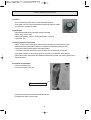
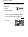
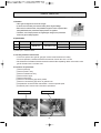
❑ What is a Dryer?
1. What is a Dryer?
A lifter, operated by a rotating drum, rolls laundry in the drum, and hot air heated by electricity (or gas) dries the
laundry through time or sensor dry system (a temperature control system) under various conditions.
2. Key Features
◆ Large Capacity/Time-Saving
• A large quantity of laundry can be dried at a time, saving energy as well as time.
◆ Automatic Digital Dry
• The digital sensor measures the humidity of laundry for optimum drying.
◆ Large Door and Automatic Dry
• The dryer has a large transparent door for convenient laundry dropping and checking.
◆ Dust Filter
• Fluff and dust are filtered during the drying process.
◆ Sterilizing Dry
• The high-temperature air dries laundry with sterilizing effects.
◆ Drying Shoes
• The dryer rack provided with the unit helps drying shoes as well as sensitive fabric.
◆ Child Lock
• This is the function that protects children from harm during the drying process.
2
3. Key Functions
◆ Dry Time
• Adjust the length of time for drying.
◆ Sensor Dry
• Automatically dry according to the types of laundry.
◆ Rack Dry
• Dry sensitive shoes and fabric(e.g. sweaters, silk, lingerie) on the rack.
◆ Anti-crease
• Prevent wrinkles in case laundry stays in the drum after the drying process.
◆ Damp Signal
• Signals when laundry is damp enough to be ironed.
◆ Delay Start
• Preset time indicates staring time of the cycle.
3
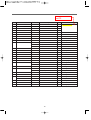
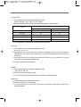
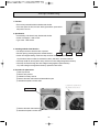
❑ Dryer Specification
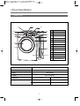
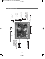
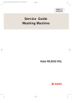
1. Product Look
5
9
14
No.
Parts
10
8
1
FRAME DOOR O
13
3
12
2
PROTECTOR GLASS
11
3
PANEL FRONT
4
CABINET FRONT
5
PLATE TOP
2
6
CABINET
7
BUTTON FUNCTION
1
8
BUTTON OPTION
9
WINDOW COURSE
10
DIA KNOB
11
BUTTON DELAY
12
BUTTON START
13
BUTTON POWER
14
WINDOW DISPLAY
7
6
4
Dimensions
27" (68.6cm)x 32" (81.2cm)x 40 3/8" (102.5cm)x52” (132cm)
W x D x H x Depth with door open
Weight
129 lb. (58.5 kg)
Capacity
Rated Power
Rating
IEC 7.3 cu.ft (22.9lb)
Electric
Gas(LNG/LPG)
120/240V 60Hz
120V 60Hz
23.5A 5300W
5A 22.9lb
4
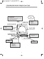
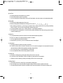
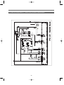
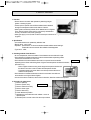
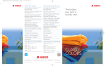
❑ Operating Mechanism Diagram (Gas Type)
Electric Input
✯ Operating Mechanism
• Controller operation
• Operator/gas burner/air supplier/ventilator operation
• Automatic operation of the controller
• Drying by the automatic sensor
Program
lifter
plate top
control pannel
4. Heat Exchanger & Dryer
• DRUM
• LIFTER
• Drying temperature sensor
1. Controller
• MAIN PCB
• FRONT PCB
• HARNESS
• POWER CORD ASS'Y :15A
duct inlet
door
Laundry
cabinet front
filter as
3. Gas Burner
• Gas Valve AS(LNG, LPG)
• THERMOSTAT
duct outlet
impeller fan
5. FILTERING
• FILTER ASS'Y
6. Air-Ventilator
• Air-vent duct
2. Drive
• IMPELLER FAN
• MOTOR ASS'Y
• THERMOSTAT
• BELT/IDLER ASS'Y
5
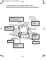
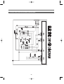
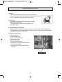
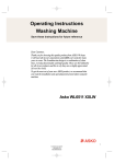
❑ Operating Mechanism Diagram (Electric Type)
Electric Input
✯ Operating Mechanism
• Controller operation
• Operator/heater/air supplier/ventilator operation
• Automatic operation of the controller
• Drying by the automatic sensor
Program
lifter
1. Controller
• MAIN PCB
• FRONT PCB
• HARNESS
• TERMINAL BLACK
(240V 60Hz)
plate top
control pannel
4. Heat Exchanger & Dryer
• DRUM
• LIFTER
• Drying temperature sensor
duct inlet
door
Laundry
heater as
cabinet front
filter as
3. Heater
• HEATER
ASS'Y(5KW)
• THERMOSTAT
• DUCT INLET
impeller fan
duct outlet
5. FILTERING
• FILTER ASS'Y
6. Air-Ventilator
• Air-vent duct
2. Drive
• IMPELLER FAN
• MOTOR ASS'Y
• THERMOSTAT
• BELT/IDLER ASS'Y
6
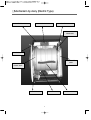
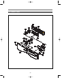
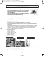
❑ Mechanism by Ass’y (Electric Type)
PLATE TOP ASS'Y
MAIN PCB ASS'Y
CABINET ASS'Y
DRUM SUPPORT
REAR ASS'Y
PANEL F ASS'Y
DUCT IN LET
ASS'Y
DRUM SUPPORT
FRONT ASS'Y
CABINET F ASS'Y
MOTOR ASS'Y
7
DRUM ASS'Y
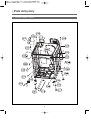
❑ Mechanism by Ass’y (Gas Type)
PLATE TOP ASS'Y
MAIN PCB ASS'Y
CABINET ASS'Y
DRUM SUPPORT
REAR ASS'Y
PANEL F ASS'Y
DUCT IN LET
ASS'Y
DRUM SUPPORT
FRONT ASS'Y
CABINET F ASS'Y
GAS BURNER
ASS'Y
8
DRUM ASS'Y
❑ Parts List by Ass’y
1. DRYER CBINET ASS'Y
9
We also need RR
and PP
No.
Part Name
Part Code
Description
Qtt'y
Remark
C01
CABINET
3610812350
SGCC 0.8T
1
C02
FRAME TOP L
3612206500
SGCC 1.6T
1
C03
FRAME TOP R
3612206600
SGCC 1.6T
1
C04
BASE UNDER
3610392900
SGCD 0.8T
1
C05
LOCK HARNESS M
3613802400
NYLON
12
C06
FRAME UPPER AS
3612207910
SGCC 1.2T + FORM
1
-
SCREW TAPPING
7122401411
T2S TRS 4x14
6
COVER BACK
3611427900
SGCC 0.6T
1
SCREW TAPPING
7112401411
T1 TRS 4x14
12
For fixing Cover Back
COVER DUCT
3611428010
ABS, WHITE
2
TL751/G/CA XXLW
3611428060
ABS, PLATINUM
2
TL751/G/CA XXLPP
3611428070
ABS, RED ROSE
2
TL751/G/CA XXLRR
C07
C08
C09
FIXTURE PLATE
3612008000
POM
6
-
SCREW TAPPING
7121401211
T2S PAN 4x12
6
C10
SUPPORTER LEG F
3615304200
SECC 3.0T
2
C11
SUPPORTER LEG R
3615304300
SECC 3.0T
2
C12
FIXTURE LEG
3612006400
ABS
4
C13
FOOT AS
3612100700
HYBRA+NYLON66
4
7122401411
T2S TRS 4x14
C14
C15
SCREW TAPPING
PCB DRYER MAIN AS
SCREW TAPPING
HARNESS AS
1 PIECE SVC PART
For fixing Frame Upper to Cabinet
For fixing Plate T & Cabinet F
2
For fixing Supporter Leg F/R
PRPSSWAD40 UL, Electric main
1
Electric type
PRPSSWAD60 UL, Gas main
1
Gas type
2
For fixing Main PCB to Cabinet
7122401411
T2S TRS 4x14
3612797000
UL, E-Dryer Main Harness
1
Electric type
3612797300
CSA, G-Dryer Main Harness
1
Gas type
-
SCREW TAPPING
7121401411
T2S TRS 4x14
6
For fixing Terminal Block
-
SPECIAL SCREW
7S422X4081
TT3 TRS 4x8 SE MFZN
2
For fixing Earth Wire
C16
COVER TERMINAL
3611428100
SGCC 1.0T
1
Electric type
CORD POWER AS
3611340400
UL.SJT 16AWG 3C 125V 13A LP31
1
Gas type
For fixing Cover Terminal
-
SCREW TAPPING
7112401411
T1 TRS 4x14
1
C17
PIPE EXHAUST AS
3614413500
SGCC 0.5T + SECC 0.8T
1
-
SCREW TAPPING
7112401008
T1 TRS 4x10 SUS
1
10
For fixing Pipe Exhaust AS
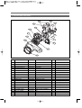
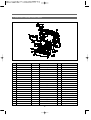
2. DRYER MOTOR ASS'Y
M03
M07
M04
M02
M06
M01
M09
M14
M05
M15
M12
M11
M08
M10
M13
M16
No.
M01
M02
M03
M04
M05
M06
M07
M08
M09
M10
M11
M12
M13
M14
M15
M16
Part Name
BRACKET MOTOR
MOTOR DRYER
CLAMP MOTOR
BRACKET IDLER AS
SPRING IDLER
SPECIAL BOLT
SWITCH MICRO
SCREW TAPPING
CASE FAN F
CASE FAN R
GASKET PIPE
SCREW TAPPING
THERMOSTAT FAN
SCREW TAPPING
THERMISTOR FAN
SCREW TAPPING
FAN IMPELLER AS
SPECIAL WASHER
SPECIAL NUT
COVER FAN
Part Code
Description
Qtt'y
3610608500
36189L5D00
3611206000
3610609100
3615115500
3616039000
3619047500
7121301611
3611144900
3611145000
3612323200
7112401411
3619047900
7121300811
361AAAAC20
7122401411
3611886200
3616039100
3616039200
3611428200
SGCC 2.0T
AC 120V 60Hz
SK5 0.7T
DWR-WE31
HSW3
S18A M6x10(FLANGE)
UL. 16A 250AC HINGE LEVER. N-C 200G
T2S PAN 3x16
PP(Heat resisting)
PP(Heat resisting)
EPDM(320*15*2.0t)
T1 TRS 4x14
UL.70ON.85OFF.125V/15A,250V/7.5A
T2S PAN 3x8
UL-DRYER.R40=26.065K.R90=4.4278K
T2 TRS 4x14
PP(Heat resisting)+BUSHING
SPC
NUT HEX 3/8-24 UNF LH
PP(Heat resisting)
1
1
2
1
1
1
1
2
1
1
1
3
1
2
1
1
1
1
1
1
11
Remark
For fixing micro s/w
For fixing case fan to bracket motor
For fixing thermostat fan
For fixing thermistor fan
3. GAS BURNER ASS'Y
not DC12V, please
check.
No.
Part Name
G01
VALVE GAS AS
G02
G03
G04
G05
G06
G07
G08
G09
G10
G11
G12
G13
G14
G15
G16
G17
G18
G19
G20
G21
G22
SCREW TAPPING
GUIDE BUNNER
MIXING VENTURI AS
SCREW TAPPING
BRACKET IGNITER
SCREW TAPPING
SCREW TAPPING
IGNITER AS
O-RING
PIPE AS
SCREW TAPPING
CAP PIPE
FIXTURE FUNNEL
FUNNEL
SCREW TAPPING
SENSOR FLAME
SCREW TAPPING
THERMOSTAT CUT-OUT
SCREW TAPPING
THERMOSTAT HI-LIMIT
SCREW TAPPING
Part Code
Description
Qtt'y
3615417200
3615417300
3612511100
3612209200
3610609400
36189L5800
3614604100
3614413800
3610918200
3612009200
3612511300
3614825700
3619047810
3619047610
-
DC12V,130mA
DC12V,130mA
T1 M4*8
SGCC 1.0T
VENTURI AS+ FLAME DAMPER
T1 M4*8
SGCC 1.6T
T1 M4*8
T1 M4*8
Ceramic type 120V 60Hz 4A
HNBR 1
Pipe+Fixture+connector
PS/W 4°ø12
PP
SGCC 2.0T
ALCOSTA 0.7T
T1 M4*8
CSA, 5.75A 120V 60Hz 10RS
T1 M4*8
110°C OFF / - 35°C ON
T1 M4*8
95°C OFF / 70°C ON 125V 25A
T1 M4*8
1
1
4
1
1
2
1
1
1
1
LPG type
LNG type
For fixing G01 & G03
1
2
1
1
1
2
1
1
1
2
1
2
WELDING
For fixing G01 & G11
12
Remark
WELDING(SPOT)
For fixing G03 & G06
For fixing G09 & G06
For fixing G14 & G15
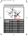
4. INLETDUCT ASS'Y
4-1. Electric Type
4-2. Gas Type
A02
A01
A04
A05
A06
A03
No.
Part Name
A01
DUCT INLET REAR
A02
DUCT INLET FRONT
A03
A04
A05
A06
HEATER AS
THERMOSTAT HI-LIMIT
THERMOSTAT CUT-OUT
HARNESS HEATER(DRYER)
-
SCREW TAPPING
SCREW TAPPING
Part Code
Description
Qtt'y
Remark
3617510200
3617510210
3617510300
3617510310
3612802500
3619047600
3619047800
3612797000
3612797300
7122400811
7122400811
WE31'S, ALCOSTA 0.6T
WG31'S, ALCOSTA 0.6T
WE31'S, ALCOSTA 0.6T
WG31'S, ALCOSTA 0.6T
240V 5000W
125°C OFF / 94°C ON 250V 25A
140°C OFF / -35°C ON 250V 25A
UL.E-DRYER.MAIN-HARNESS
UL/CSA, GAS-DRYER, ON/OFF-VALVE
T2S TRS 4x8 MFZN
T2S TRS 4x8 MFZN
1
1
1
1
1
1
1
1
1
12
4
ELECTRIC TYPE
GAS TYPE
ELECTRIC TYPE
GAS TYPE
ELECTRIC TYPE
ELECTRIC TYPE
ELECTRIC TYPE
ELECTRIC TYPE
GAS TYPE
FOR FIXING DUCT INLET F & R
FOR FIXING SENSOR
13
5. SUPPORT DRUM REAR ASS'Y
B07
B02
B03
B01
B02
B04
B05
No.
B01
B02
B03
B04
B05
B06
B07
Part Name
SUPPORT DRUM REAR
BRACKET SUP.R-SIDE
BRACKET SUP.R-UPPER
SCREW TAPPING
ROLLER AS
WASHER SHAFT
NUT HEX
DUCT INLET AS
Part Code
3615304500
3610608810
3610608910
7122401411
3614714400
3616039400
3616039300
3617510100
3617510110
Description
STS430 2B 0.8T
SGCC 1.0t
SGCC 1.0t
T2 TRS 4x14 MFZN
ASSY
T=1.6 ID=10.0 OD=25
M10 P1.5
ELECTRIC, DUCT INLET AS
GAS, NON-HEATER
14
B06
Qtt'y
1
2
1
7
2
2
2
1
1
Remark
For fixing bracket supp.up & side
For fixing roller as
For fixing roller as
Refer to 13 page
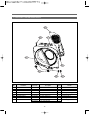
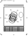
6. SUPPORT DRUM FRONT ASS'Y
No.
Part Name
Part Code
Description
Qtt'y
S01
SUPPORT DRUM F
3615304600
SECD 0.8T
1
S02
HOUSING LAMP
3613053400
PP(Heat Resisting)
1
S03
SOCKET LAMP
3613053300
14 BASE LEAD WIRE TYPE
1
S04
LAMP
3613625400
AC 125V 15W
1
S05
WINDOW LAMP
3615505100
ABS(Transparent)
1
-
SCREW TAPPING
7112401208
T1 TRS 4x12 SUS
1
S06
ROLLER AS
3614714400
WE31'S Roller As
2
S07
WASHER SHAFT
3616039400
T=1.6 ID=10.0 OD=25
2
S08
NUT HEX
3616039300
M10 P1.5
2
S09
BODY FILTER R
3611909700
PP(Heat resisting)
1
S10
BODY FILTER F
3611909600
PP(Heat resisting)
1
S11
FILTER AS
3611909810
PP+NYLON MESH
1
Remark
For fixing Window Lamp to Sup.Drum F
Insert injection
S12
DUCT OUTLET AS
3617510400
ALCOSTA 0.6T
1
-
SCREW TAPPING
7122401408
T2S TRS 4x14 SUS
3
For fixing Body Filter to Sup.Drum F
-
For fixing Duct Outlet As to Sup.Drum F
SCREW TAPPING
7122401408
T2S TRS 4x14 SUS
3
S13
SENSOR MOISTURE
3614825500
STS430 2B 0.8T
2
S14
FIXTURE SENSOR A
3612009600
PP(Heat resisting)
1
Located center position
S15
FIXTURE SENSOR B
3612009700
PP(Heat resisting)
1
Located right position
S16
HARNESS SENSOR
3612797200
UL. DRYER. SUB-SENSOR
1
S17
LOCK HARNESS
3613802400
M TYPE 15x19
1
15
For fixing Harness Sensor to Sup Drum F
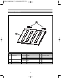
7. DRUM ASS'Y
D01
D03
D04
D02
D05
D04
D03
No.
Part Name
Part Code
Description
Qtt'y
D01
DRUM
3617011000
STS430 J1L 0.5T
1
D02
LIFTER
361A401050
Heat resisting PP
3
-
SCREW TAPPING
7122502008
T2S TRS 5x20 SUS
12
D03
SEAL DRUM AS
3614010600
Felt + Synthetic leather
2
D04
PAD DRUM
3614111100
BUTYL
6
D05
BELT V
3616591200
POLY TYPE 2,340mm
1
16
Remark
For fixing lifter
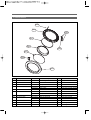
8. DOOR ASS'Y
R09
R01
R05
R07
R02
R04
R03
R08
R06
No.
Part Name
R01
R02
R03
R04
FRAME DOOR I
GLASS DOOR
PROTECTOR GLASS
HINGE DOOR AS
R05
R06
CAP HINGE DOOR
FRAME DOOR O
R07
R08
GASKET DOOR
COVER HANDLE
R09
-
HOOK DOOR
SCREW TAPPING
SCREW TAPPING
Part Code
Description
Qtt'y
3612208000
36117ABR00
3618304300
3612903610
3612903640
3610916500
3612208120
3612208110
3612323000
3611428320
3611428310
3613101100
7115401608
7115402008
Heat resisting PP
Glass
Transparent ABS
Zn-Dc, WHITE
Zn-Dc, GRAY
POM
ABS, SILVER DOOR
ABS, CROM DOOR
TPE
ABS, SILVER DOOR
ABS, CROM DOOR
POM
FLT 4x16 SUS
T1S FLT 4x20 SUS430 NATURAL
1
1
1
1
1
2
1
1
1
1
1
1
1
15
17
Remark
TL751/G/CA XXLW
TL751/G/CA XXLPP, XXLRR
TL751/G/CA XXLW
TL751/G/CA XXLPP, XXLRR
TL751/G/CA XXLW
TL751/G/CA XXLPP, XXLRR
For fixing Hook Door
For fixing Door O & I
9. PLATE TOP ASS'Y
No.
T01
T02
Part Name
PLATE TOP AS
HANDLE REAR
(PLATE SUPPORTER)
-
SCREW TAPPING
Part Code
Description
Qtt'y
Remark
PRMACA3R00 WHITE
1
TL751/G/CA XXLW
PRMACA3R20 PLATINUM
1
TL751/G/CA XXLPP
PRMACA3R60 RED ROSE
1
TL751/G/CA XXLRR
3615304100
ABS
2
7122401411
T2S TRS 4x14 MFZN
4
18
10. CABINET FRONT ASS'Y
G01
G03
G07
G05
G08
G04
G02
G09
G06
No.
Part Name
G01
CABINET FRONT AS
G02
G03
GASKET CABINET F
SUPPORT HINGE
G04
G05
G06
G07
G08
G09
DOOR LOCK AS
SCREW MACHINE
SWITCH DOOR
DOOR AS
SCREW TAPPING
LABEL WARNING F
LABEL CAUTION F
LABEL RATING
Part Code
Description
3610812510
3610812550
3610812560
3612323350
3615304410
3615304415
3613802500
7002401608
3619047700
3616030000
3613558800
3613557600
3613558900
WHITE
PLATINUM
RED ROSE
EPDM 5x10 3.0T R207
SGCC 1.6t
T2S TRS 4x16 SUS430
125V 7.5A
F/L BOLT(SE) 5x12 SUS
PVC
PVC
PVC
19
Qtt'y
1
1
1
4
1
1
1
2
1
1
4
1
1
1
Remark
TL751/G/CA XXLW
TL751/G/CA XXLPP
TL751/G/CA XXLRR
LEFT DOOR TYPE
RIGHT DOOR TYPE
For fixing door lock as
Refer to 17 page
For fixing hinge & cabinet f
11. PANEL F ASS'Y
20
No.
P01
P02
P03
P04
P06
P05
P07
P08
P09
P10
Part Name
PANEL F
BUTTON POWER
WINDOW COURSE
BUTTON START
WINDOW DISPLAY
BUTTON OPTION
BUTTON FUNCTION
DIAL KNOB OUTER
DIAL KNOB INNER
Part Code
3614288900
3616637800
3615506300
3616637900
3615506400
3616638100
3616638000
3616638200
3616638300
Description
Qtt'y
Remark
ABS + SILK PRINT, WHITE
1
TL751/G/CA XXLW
ABS + SILK PRINT, PLATINUM
1
TL751/G/CA XXLPP
ABS + SILK PRINT, RED ROSE
1
TL751/G/CA XXLRR
ABS + SILK PRINT, WHITE
1
TL751/G/CA XXLW
ABS + SILK PRINT, PLATINUM
1
TL751/G/CA XXLPP
ABS + SILK PRINT, RED ROSE
1
TL751/G/CA XXLRR
ABS(Transparent) + Film, WHITE
1
TL751/G/CA XXLW
ABS(Transparent) + Film, PLATINUM
1
TL751/G/CA XXLPP
ABS(Transparent) + Film, RED ROSE
1
TL751/G/CA XXLRR
ABS + SILK PRINT, WHITE
1
TL751/G/CA XXLW
ABS + SILK PRINT, PLATINUM
1
TL751/G/CA XXLPP
ABS + SILK PRINT, RED ROSE
1
TL751/G/CA XXLRR
ABS(Transparent) + Film, WHITE
1
TL751/G/CA XXLW
ABS(Transparent) + Film, PLATINUM
1
TL751/G/CA XXLPP
ABS(Transparent) + Film, RED ROSE
1
TL751/G/CA XXLRR
ABS, WHITE
1
TL751/G/CA XXLW
ABS, PLATINUM
1
TL751/G/CA XXLPP
ABS, RED ROSE
1
TL751/G/CA XXLRR
ABS, WHITE
1
TL751/G/CA XXLW
ABS, PLATINUM
1
TL751/G/CA XXLPP
ABS, RED ROSE
1
TL751/G/CA XXLRR
ABS, WHITE
1
1 Piece SVC Part
ABS, PLATINUM
1
=> DIAL KNOB INNER &
ABS, RED ROSE
1
OUTER
ABS, WHITE
1
ABS, PLATINUM
1
ABS, RED ROSE
1
ABS(Transparent)
1
LED COURSE
3613054700
P11
HOLDER COURSE
3613054500
ABS
1
P12
HOLDER FUNCTION
3613054600
ABS
1
P13
PCB F AS
P14
CASE PCB FRONT
3611147600
ABS
1
P15
CAP SCREW
3610917700
ABS, WHITE
1
TL751/G/CA XXLW
ABS, PLATINUM
1
TL751/G/CA XXLPP
PRPSSWAD55 ASKO DRYER
1
ABS, RED ROSE
1
TL751/G/CA XXLRR
-
SCREW TAPPING
71224012411
T2S TRS 4x12 MFZN
1
For fixing Panel F to Frame Upper
-
SCREW TAPPING
71224012411
T2S TRS 4x12 MFZN
7
For fixing Case PCB F to Panel F
-
LABEL WIRING
3613557800
WE31'S WIRING
1
Panel F Back
21
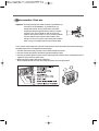
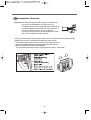
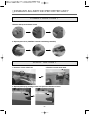
12. Procedure for Reversing the Door
Door hanging
5. Next insert the hinge of the door securely in
place of the left side of the front cabinet.
The tumble dryer come with the door hinged on
the right. However, it is possible to change the
door to be hinged on the left.
Following these instructions:
1. Open the door and remove the two bolts
holding the hinge.
6. Secure the hinge using the bolts you removed
in step 1.
2
2. Then remove the door out of the front cabinet
as indicated by the arrows.
1
3. Unscrew the four screws on the door lock on
the left side of the front cabinet and move to
the right side.
4. Replace the screws you removed in step 3.
22
❑ PCB Function Specification
1. Front PCB Function Specification
Comprehensive function specification of the unit including operation of a 27-inch dryer by drying courses and drying
functions, control of electronic devices by PCB, operation by S/W, test function, error mode, and so on.
No.
Index
1
Features of the
dryer
2
Course and
Operation
Descriptions
1. Applied model: dryer for use in U.S. & CANADA.
2. Power source: ELECTRIC / LNG / LPG
3. Heating type: HEATER / GAS
4. Voltage: PCB & MOTOR 120V 60Hz / HEATER 240V 60Hz
5. PCB type: Front PCB (shared with other models)
Main PCB (3 types) : ELECTRIC, GAS ON/OFF CONTROL,
GAS PROPORTIONAL CONTROL
1. Sensor drying courses - 7
Manual drying courses – 3
2. Setting - 7
3
Adopted sensors
4
Load control
5
Display
1. Humidity sensor
2. Temperature sensor: at the duct outlet
1. Motor
2. ELECTRIC HEATING : HEATER 2.5KW 2UNIT
3. GAS VALVE : ON/OFF CONTROL / PROPORTIONAL CONTROL
1. Course and operation display : Lamp LED + 18:88
23
Miscellaneous
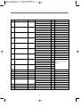
2. Detailed Descriptions
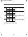
2-1. Setting by Courses
1) Sensor Dry Course
COURSE - SENSOR DRY
Very Dry
More Dry
DRY LEVEL
Normal
Less Dry
Damp Dry
Dry Level Default
TEMP CONTROL
Very Dry
More Dry
DRY LEVEL
Normal
Less Dry
Damp Dry
Dry Level Default
Temp Control
Synthetics
1:01
54
47
40
33
Normal
Medium
Everyday Wear
1:05
1:02
59
56
53
Normal
Mid High
Towels
1:05
55
50
45
40
Normal
High
Bulky Items
1:10
1:00
55
50
45
Normal
High
COURSE - SENSOR DRY
Gentle
Ultra Gentle
Iron Dry
1:00
55
50
45
40
35
30
25
20
20
25
Normal
Normal
Damp Dry
Low
Low
Ultra Low
A. Temperatures are not changed in Sensor Dry Course so the initial setting is not altered.
B. Temp Level is set to “High” while Dry Level is set to “Very Dry”.
C. All options of Dry Level can be selected in Sensor Course.
D. The course can not be changed when the unit stops operating temporarily in Sensor Dry and Manual Dry
Course.
24
2) Manual Dry Course
COURSE - MANUAL DRY
TEMP
Time
CONTROL
Temp Default
DRY LEVEL
TEMP
Quick Dry
30
High
Ultra Low ~ High
FRESHEN UP
30
Mid high
Ultra Low ~ High
AIR DRY
35
-
A. Only Temp is selected in Manual Dry Course.
B. Dry Level is not selected in Manual Dry Course and Iron Dry.
C. Operation time does not change even if Temp is changed.
D. Dry Level and Course LED are off (not selected) if Dry Time is set while only Temp is on (the default set is High).
E. Time can be changed by using More Time and Less Time buttons when Manual Dry Course and Dry Time are
selected.
F. Pushing More Time or Less Time button increases or decreases time by a minute. The maximum drying time is
1:50 (minutes) and minimum 0:10 (minutes). This includes 5 minutes of cooling time.
25
2-2. Operation
1) Overview
➔ Different operation processes are applied to Sensor Dry Course and Manual Dry Course.
➔ Sensor Dry Course judges the condition of laundry with humidity/temperature sensors so as to decide
appropriate dry level.
➔ Manual Dry Course dries laundry as per temperature conditions set by an operator.
2) Process of Sensor Dry Course
A. Power Button On
➔ “_ _ _” is displayed at 18:88 LED.
➔ Press Start Button to automatically select Normal Course.
➔ “High” of initial Beeper goes on and the previous Beeper value is displayed when you switch
on the power.
B. Operation Selection
➔ Select operation with Course Switch/Button.
➔ Buttons operate as per 2-1.
➔ The selected Course/Dry Sensor/Temp./Dry Time/Signal goes on.
➔ Option LED may go on and off according to your selection.
26
3) Process of Manual Dry Course
A. Power Button On
➔ “_ _ _” is displayed at 18:88 LED.
➔ “Check Filter” of Custom LED goes on and off before you press Start Button.
➔ “High” of initial Beeper goes on and the previous Beeper value is displayed when you switch
on the power.
B. Operation Selection
➔ Select operation with Course Switch/Button.
➔ “Check Filter” of Custom LED goes on and off before you press Start Button. Once the unit starts
operating, “Check Filter” goes off.
➔ Buttons operate as per 2-1.
➔ The selected Course/Dry Level/Temp Control/Time Dry/Beeper goes on and Custom LED displays
Dry/Cooling.
➔ Option LED may go on and off according to your selection.
C. Operation Process
➔ Once operation starts, LED of Custom LED goes off.
➔ Humidity data are not produced and Heater is controlled by the temperature set by Temp Control.
➔ Time is not changed but drying/cooling continues during the time set initially.
4) Process of Time Dry Course
A. Selection of Time Dry
➔ Course Selection foes off.
➔ Dry Level can not be selected (Default: “High”) but only Temp Control.
➔ Buttons operate as per 2-1 (Same as Manual Dry).
B. Operation Process
➔ The process is the same as Manual Dry.
➔ “Check Filter” of Custom LED goes off if you press Start Button.
27
2-3. Operation of Load and Sensor
1) Operation of Heater - Electric Type
➔ On/Off goes on according to temperatures set or measured by the sensor. Regardless of the control by
the microcomputer, however, the heater may go off if a temperature reaches Thermostat Off
Temperature as per outlet conditions.
➔ As regards temperature setting, refer to 2-4 (button operation and temp control).
➔ If you stop the unit temporarily, the machine stops operating until it resumes the function.
➔ If Sensor Course is selected and Temp Control is set to Low or Ultra Low, only the outer heater
operates. Two heaters function if other temperatures are selected.
➔ If Manual Course is selected and Temp Control is set to Low or Ultra Low, only the outer heater
operates. Two heaters function if other temperatures are selected.
➔ If Time Dry Course is selected and Temp Control is set to Ultra Low, only the outer heater operates.
Two heaters function if the temperature is set to Low.
➔ The heater goes off if Cooling or Wrinkle Care is selected.
➔ The heater goes off if Air-Dry of Manual Course is selected, for Temp Control is not available.
2) Operation of Gas Valve - On/Off Type
➔ Gas valve is continuously turned on/ off according to the temperature measured by temperature
sensor to reach the set temperature. However, when reaching the temperature for thermostat off by
exhaust conditions, gas valve can be turned off regardless of MICOM control.
➔ For temperature set values, refer to 4) Temp Control of Section 2-4.
➔ At temporary suspension, operation is stopped. Then, it starts again as the cycle begins.
➔ Gas valve is not turned off in cooling and winkle care cycle.
➔ In manual course, gas valve for air dry of which temp control is not selected does not operate.
3) Operation of the Motor
➔ The motor continues its function once operation starts.
➔ The motor stops if you stop the unit temporarily.
➔ The motor continues to operate during Cooling.
➔ If Cooling or Wrinkle Care is selected, the motor turns on for 10 seconds and off for 5 minutes and 50
seconds.
4) Door Control
➔ The heater and motor operate only the door is closed.
➔ If the door is opened during the operation, the heater and motor turn off. If you press Start Button while
the door is opened, LED goes on for a second.
➔ The unit operates only after the door is closed.
28
2-4. Operation of Buttons
1) Power
A. The electric power switch turns on/off the display.
B. Automatic switch off function
1 Power is immediately switched off after an operation is done.
2 Power is switched off after 10 minutes if no button is selected while power is on.
C. Initial display when power goes on
1 LED of all courses goes on in order.
2 “_ _ _” is displayed at 18:88 LED.
2) Start/Pause
A. Normal Course is operated if you press the button after switching on the power.
B. Operation starts after you select one of 11 automatic and program courses.
C. If you press this button while the unit is in operation, the on-and-off indicator goes on and the machine
stops. If you press the button again, the operation is resumed.
D. If you press Pause Button, other buttons or the encoder switch does not function. That is, you can not
change the operation once it starts unless switching off the power.
1 Power is immediately switched off after an operation is done.
2 Power is switched off after 10 minutes if no button is selected while power is on.
3) Dry Level
A. If you press this button, the following is displayed in order.
Normal-More Dry-Very Dry-Damp Dry-Less Dry-Normal
B. Each level targets humidity as follows.
Dry Level
Target Humidity
Damp Dry
80%~92%
Less Dry
88% ~ 96%
Normal
92% ~ 100% or higher
More Dry
94% ~ 100% or higher
Very Dry
96% ~ 100% or higher
C. You can select all levels in Sensor Dry Course but none in Manual Dry Course.
29
4) Temp Control
A. If you press this button, the following is displayed in order.
Medium - Mid High - High - Ultra Low - Low - Medium
B. Each level targets temperatures as follows. (Target temperatures : Thermostat fan)
Level
Target Temperatures
Heater-Off(°C)
Heater-On(°C)
High
63
58
Mid High
59
54
Medium
55
50
Low
50
45
Ultra Low
46
41
C. This is available only in Manual Dry Course not Sensor Dry Course.
5) Time Dry
A. If you press this button, the following is displayed in order.
40 - 50 - 60 - 20 - 30 - 40
B. Pushing More Time or Less Time button increases or decreases time by a minute. The maximum
drying time is 1 hour and 50 minutes and minimum 10 minutes (the indicated time includes 5 minutes
of cooling).
C. If you select Time Dry, Dry Level and Course LED go off. That is, you can not choose Dry Level and
Course but only temperatures (default is High).
D. 5 levels of temperatures are available.
6) Beeper
A. If you press this button, the following is displayed in order.
'High - ▼ - Low - ▼ - Off'
B. Then, the volume of the beeper changes.
C. You can not change the beeper while the unit is in operation or stops temporarily.
7) More Time
A. Pressing this button increases time by a minute.
B. The time increases up to 1:55 (minutes)
C. You can change time in Manual Dry Course and Time Selection. Also Wrinkle Care can be
selected/cancelled.
30
8) Less Time
A. Pressing this button decreases time by a minute.
B. The time decreases up to 00:15 (minutes)
C. You can change time in Manual Dry Course and Time Selection. Also Anti-crease can be selected/cancelled.
9) Delay Start
A. Preset time indicates starting time of the cycle.
12 1.
B. When pressing Delay Start button, time changes in the order of 1 2 3 4
C.After selecting preset time, cycle change is possible before entering preset mode by pressing Start/Stop
button. However, cycle cannot be changed after entering preset mode.
D. To preset operation, select cycle select preset time press Start/ Stop button.
E. The selected cycle is displayed for 3 seconds when pressing Start/Stop button after entering preset mode to
check the selected cycle.
10) Rack Dry
A. If you press Rack Dry button, time is set to 55 minutes without default temperature.
B. Only Low or Ultra Low is selected with the operation of Heater 1.
C. You can adjust time with More/Less button.
D. Once Rack Dry is chosen, you can not select Anti-crease, Damp Signal.
11) Anti-crease
A. Selecting Wrinkle Care does not change course time.
B. In order to prevent wrinkle, the motor continues to run for 10 seconds and stops for 5 minutes and 50 seconds
while the heater is off after all the operation (including cooling) finishes.
C. The course stops only you press Start/Stop or Power button.
D. You can select/cancel this course during operation or pause.
12) Child Lock
A. Child lock mode begins by pressing and holding Child Lock for 3 seconds.
B. In child lock mode, all the buttons, with the exception of power button are not operated.
C. Child lock mode is cleared by pressing and holding Child Lock for 3 seconds again.
13) Damp Signal
A. This button works only in Sensor Dry Course without changing time.
B. The unit beeps every 3 seconds after the target humidity is achieved until the operation is finished.
C. The beep stops if the door is opened or operation stops. When the operation is resumed, the beeper is off.
31
2-5. Option
Programs
Bulky Items
Towels
Everyday
Wear
Synthetics
Gentle
Ultra
Gentle
Iron Dry
Quick Dry
Freshen
Air Dry
Dry Sensor Temperature
Default
Select
Default
Select
Default
Select
Default
Select
Default
Select
Default
Select
Default
Select
Default
Select
Default
Select
Default
Select
Normal
All
Normal
All
Normal
All
Normal
All
Normal
All
Normal
All
Damp dry
X
X
X
X
High
X
High
X
Mid.High
X
Medium
X
Low
X
Low
X
Ultra low
X
High
Ultralow~high
Mid High
Ultralow~high
X
More Time
Less Time
Rack Dry
Anti-crease
Delay Start
Damp
Signal
X
O
O
X
O
O
X
O
O
X
O
O
X
O
O
X
O
O
X
O
O
O
O
X
O
O
X
O
O
X
A. If you select Rack Dry, the previous course and operation goes off.
B. If you select Rack Dry, Anti-crease or Damp Signal is not available.
32
2-6. Error Mode
1) H1 error - Humidity sensor error
1 This occurs when there is a short defect in the humidity sensor (the indicated value is lower than 24)
2 The unit buzzes, indicating the error, every 10 minutes for 10 seconds.
3 The error display goes off when the power is switched on/off.
2) H2 error - Drying temperature sensor open/short error
1 This occurs when there is a defect in the drying temp sensor or disconnection.
2 The unit buzzes, indicating the error, every 10 minutes for 10 seconds.
3 The error display goes off when the power is switched on/off.
3) H5 error - Heater overheated (ELECTRIC TYPE)
1 This occurs when the temp sensor indicates 85° or higher.
4) Heater disconnection check and H4/H6 error (ELECTRIC TYPE)
1 No error is indicated in case of actual consumer use, for this mode checks heater defects through
customer service.
2 The defect must be checked without any load.
3 How to enter the mode: Push the power button while Dry Beep and More buttons are pressed at the
same time.
4 Then, Heater 1, Heater 2, and the motor are turned on.
5 Check the temp initially and 2 minutes later. Measure the difference.
If the difference is 20°C or greater, “OK” is indicated.
If between 5°C~19°C, “H6” is displayed, indicating disconnection of one heater.
If 5°C or below, “H4” is displayed, indicating disconnection of two heaters.
5) H3 Error - Flame Detector Open Defect (Gas Type)
1 Prior to igniter operation, it is checked whether flame detector is attached. H3 error occurs when flame
detector is still open after 300 seconds.
6) H7 Error – Gas Valve Defect or Gas Blocked-off (Gas Type)
1 H7 error occurs if flame detector maintains short state when operating gas valve after normal
operation of flame detector and igniter (error displayed after 5 repetitions).
7) H8 Error – Igniter Defect or Flame Detector Short (Gas Type)
1 Flame detector must open within 120 seconds after igniter operation. H8 error occurs when the initial
state of short is maintained after the 120 seconds (error displayed after 5 repetitions).
33
2-7. TEST Mode
1) PCB TEST MODE
A. How to enter the mode: switch the power on while pressing Dry Level and Temp Control buttons.
B. Operation order: check load by pressing Time Dry Button continually.
No.
Operation Load
Time (Sec)
DISPLAY
Miscellaneous
1
F PCB LED ALL On
0.5
ALL LED
Shared by electric type and gas type.
2
Humidity sensor check
0.5
1 : xx
Shared by electric type and gas type.
3
Temperature sensor check
0.5
2 : xx
Shared by electric type and gas type.
4
Door S/W check
0.5
dc --> do
Shared by electric type and gas type.
5
Motor check
0.5
4 : nr
Shared by electric type and gas type.
6
Heater-Outer check / Ignitor check
0.5
5 : H1
Electric type / Gas type
7
Heater-Inner check / Valve 1 check
0.5
6 : H2
Electric type / Gas type
8
Valve 2 check
0.5
7 : H3
Gas type
9
Power off
0.3
Fc --> Fo
Shared by electric type and gas type.
Total time
18 seconds
Fixed resistance of the temp sensor : 1.7 KΩ
34
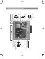
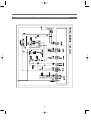
3. ELECTRIC DRYER PCB PIN LAYOUT
#
$
"!450%!: AC INPUT
&!#$#%
-!45(89!: HEATER INNER
"
"!,0',5%!: MOTOR
&!,1#9!: DOOR CHECK
#
"
"!2%55$:!: HEATER OUTTER
&!#$#%
-!:;1*%!: AC INPUT
"
#
$
MOTOR operating relay
TRANS
Heater operating relay
REGULATOR heat sink
electrolytic capacitorCapacitor
"
&
#
'
$
FRONT PCB S/W,LED
%
"!#$#% &!$'(#)%!: *%+, SENSOR2
-!'%.!: /0+1.1*2 SENSOR2
3!450%!: /0+1.1*2SENSOR
6!#$#%,7!)'%%#!: GND
35
4. GAS DRYER PCB PIN
"
#
MOTOR operating relay
#
"
"
#
$
#
"
" purple : DOOR CHECK,
& white :I GNITOR
- pink : MOTOR
$
FLAME DETECTOR
" brown & blue
VALVE controll
" black & gray
- blue
AC INPUT 120V
" black & orange
"
&
#
'
$
FRONT PCB S/W,LED
%
" none & orange : temp SENSOR2
- red : Humidity SENSOR2
3 blue : HumiditySENSOR
6 none, 7 green : GND
GAS VALVE proportional controller
IGNITER operating relay
TRANS
36
❑ Drum Dryer Troubleshooter
■ POWER/NOISE
Trouble
Symptom
Cause
Solution
Service wire
problem
A fault of Lead-in wire power
Fuse disconnection of service wire
Disconnection of the power cable
(Connection fault)
Disconnection of a controller terminal pin and
connector
Connection/terminal contact fault of a terminal
block
Call the electricity provider
or an expert
Replace the power cable
Fuse disconnection
Replace the fuse
Rating for gas type: 120V
Rating for electric type: 120V/240V
Pin connect contact fault
Circuit fault
S/W fault of Panel F
Microcomputer error
Broken plate
Harness disconnection
Check the rating
Check the rating
Check the rating
Replace PCB
Replace Panel F PCB
Replace PCB
Replace PCB
Dryer wire problem
Electric parts
Power
problem
Voltage problem
PCB problem
Noise at the initial
operation
Noise during the
Installation
Impurities in the drum
Impurities on the fan
Noise
operation
Loosened fan
Excessive laundry
Impurities between the drum and SUP F,R
Friction of the belt
37
Plug in the connector
Connect the wire
Replace/Connect Harness
Place the unit on the flat
ground
Remove the impurities
Disassemble the unit and
remove the impurities
Tighten the fan
Reduce the laundry
Remove the impurities
Replace the belt
1. ELECTRIC DRYER WIRING DIAGRAMS
38
2. GAS DRYER(ON/OFF CONTROL) WIRING DIAGRAMS
39
3. GAS DRYER(PROPOTIONAL CONTROL) WIRING DIAGRAM
40
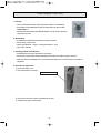
❑ Dryer Installation
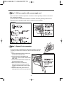
1. Installation Order
1 Place the dryer on the flat ground. Keep the unit at least 12 inch away from the wall.
2 Check the 4 legs and the gap between the unit and floor. The dryer should stand stably when
you try to move the unit to the left or right.
➤ Balance the unit on the floor with the leg adjust as so that the inclination is not greater than 1 inch.
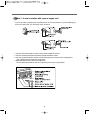
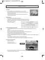
2. Outlet Duct Connection
➤ Never use a plastic or aluminum foil duct.
➤ Use a durable 4-inch metal duct (the duct outlet is provided
with the dryer. Ask local shops for an additional duct).
➤ Make the duct outlet the shortest possible length.
➤ Clean the duct before installation.
➤ Do not use a bent duct.
➤ Use aluminum tape for connection and rub for close
adhesion.
41
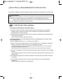
❑ ELECTRICAL REQUIREMENTS FOR ELECTRIC
The following are additional instructions regarding electrical connections and requirements for electric dryers.
Important Warning
To help prevent fire, electric shock, serious injury or death, the wiring and grounding must conform to the
latest edition of the National Electrical Code, ANSI/NFPA 70 and all applicable local regulations.
Please contact a qualified electrician to check your home’s wiring and fuses to ensure that your
home has adequate electrical power to operate the dryer.
120V/ 240V, 60 Hertz, 3-Wire Installation
Instructions for Grounding of your Electric Dryer:
a) This dryer must be connected to a grounded metal, permanent wiring system or an equipmentgrounding conductor must be run with the circuit conductors and connected to the equipmentgrounding terminal or lead on the dryer.
b) The dryer has its own terminal block that must be connected to a separate 60 Hertz single phase AC
circuit, fused at 30 Amperes
(the circuit must be fused on both sides of the line).
ELECTRICAL SERVICE FOR THE DRYER SHOULD BE OF MAXIMUM RATE VOLTAGE LISTED
ON THE NAMEPLATE.
DO NOT CONNECT DRYER TO 110, 115, OR 120 VOLT CIRCUIT.
c) If branch circuit to dryer is fifteen feet (4.50 m) or less in length, use U.L. (Underwriters Laboratories)
listed No. 10 A.W.G. wire (copper wire only), or as required by local codes.
If over fifteen feet (4.50 m), use U.L. (Underwriters Laboratories) listed No. 8 A.W.G. wire (copper
wire only), or as required by local codes.
Allow sufficient slack in wiring so dryer can be moved from its normal location when necessary.
d) The power cord (pigtail) connection between wall receptacle and dryer terminal block IS NOT supplied
with dryer.
Type of pigtail and gauge of wire must conform to local codes and with instructions mentioned on the
following pages.
e) The method of wiring the dryer is optional and subject to local code requirements. Refer to examples
on next page.
f) You must select the method by which to wire your dryer according to local code and ordinance
requirements.
Sample methods are included in the following pages.
42
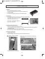
Review the following options to determine the appropriate electrical connection for your home:
Use the instructions in this section if your home has
a 4-wire receptacle (NEMA type 14-30R) and you
will be using a UL listed, 120/240 volt minimum, 30
amp, dryer power supply cord.
Use the instructions in this section if your home has
a 3-wire receptacle (NEMA type 10-30R) and you
will be using a UL listed, 120/240 volt minimum, 30
amp, dryer power supply cord.
4-wire receptacle
(NEMA type14-30R)
3-wire receptacle
(NEMA type10-30R)
If this type is available at your home. you will be
connecting to a fused disconnect or circuit breaker
box.
If this type is available at your home. you will be
connecting to a fused disconnect or circuit breaker
box.
3-wire direct
4-wire direct
43
4-wire connection : Direct wire
Important : Grounding through the neutral conductor is prohibited for (1)
new branch-circuit installations, (2) mobile homes, (3)
recreational vehicles, and (4) areas where local codes
prohibit grounding through the neutral conductor. Prepare
minimum 5 ft (1.52 m) of length in order for dryer to be
replaced. First, peel 5 inches (12.7 cm) of covering material
from end. Strip 5 inches of ground wire insulation. After
cutting 11/2 inch (3.8 cm) from 3 other wires peel insulation
back 1 inch (2.5 cm). Make ends of 3 wires a hook shape.
Then, put the hooked shape end of the wire under the screw of the terminal block (hooked end facing to
the right) and pinch the hook together and screw tightly.
1. Connect neutral wire (white) of power cord to center terminal block screw.
2. Connect red and black wires to the left and right terminal block screws.
3. Connect ground wire (green) of power cord to external ground screw and move neutral ground wire of
appliance and connect it to center screw.
4. Make sure that the strain relief screw is tightened.
Be sure that all terminal block nuts are on tight and power cord is in right position.
44
3-wire connection : Direct wire
Important : Grounding through the neutral conductor is prohibited for (1)
new branch-circuit installations, (2) mobile homes, (3)
recreational vehicles, and (4) areas where local codes prohibit
grounding through the neutral conductor. Prepare minimum 5
ft (1.52 m) of length in order for dryer to be replaced.
First, strip 3 1/2 inches (8.9 cm) of outer sheath from end and
strip 1 inch of insulation from each conductor.
Then, put the hooked shape end of the wire under the screw of the terminal block (hooked end facing
rightward) and pinch the hook together and tighten the screw securely.
1. Connect neutral wire (white) of power cord to center terminal block screw.
2. Connect red and black wires to the left and right terminal block screws.
3. Make sure that the strain relief screw is tightened.
Be sure that all terminal block nuts are on tight and power cord is in right position.
45
Option 1: 4-wire connection with a power supply cord.
• lf your local codes or ordinances do not allow the use of a 3-wire connection, or you are installing your
dryer in a mobile home, you must use a 4-wire connection.
1. Connect neutral wire (white) of power cord to center terminal block screw.
2. Connect red and black wires to the left and right terminal block screws.
3. Connect ground wire (green) of power cord to external ground screw and move neutral ground
wire of appliance and connect it to center screw.
4. Make sure that the strain relief screw is tightened.
Be sure that all terminal block nuts are on tight and power cord is in right position.
46
Option 2: 3-Wire connection with a power supply cord.
lf your local codes or ordinances permit the connection of a frame-grounding conductor to the neutral
wire, use these instructions.
If your local codes or ordinances do not allow the connection of a frame-grounding conductor to the
neutral wire, use the instructions under Section 1: Optional 3- wire connection.
Section 1
Option 3: Optional 3-wire connection.
• If your local codes or ordinances do not allow the connection of a framegrounding conductor to the neutral wire, use the instructions under this
section.
1. Connect neutral wire (white) of power cord
to center terminal block screw.
2. Connect ground wire of appliance and
neutral wire of power cord to center terminal
block screw.
3. Connect red and black wires to the left and
right terminal block screws.
4. Make sure the strain relief screw is
tightened. Be sure that all terminal block
nuts are on tight and power cord is in right
position.
5. Connect independent ground wire from
external ground connector to proper ground.
47
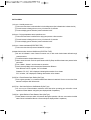
❑ Dryer Service Notices
No.
1
Service
Parts
Notices
Replacing the
Humidity sensor
Be careful of the terminal connection
humidity sensor
2
Replacing/fixing panel f assy
Be careful of loose attachment
PCB/BUTTON/HARNESS
Be sure that the panel f assy does not interfere in the
drum after the service
3
Replacing the lifter
LIFTER
Remove only the plate top to replace the part
4
Replacing roller assy
ROLLER
Be cautious of the direction of the roller/insertion of
the washer
5
Replacing the terminal block
TERMINAL BLOCK
Be careful of wiring connection
6
Replacing the heater
Drying heater
Do not use oversized screws.
Replacing the burner
GAS BUNNER
Be sure of the proper assembly.
(Loosening should be little)
Be careful that no object (e.g. screws) is dropped
into the heater when assembling.
Be careful of the direction / insertion of the
connector. Use only standard screws.
7
Replacing the sensor
Temp and safety sensor
Be careful of the direction / insertion of the connector.
Use only standard screws.
8
Door assembly
Door hinge
Be careful not to scratch chromium plating when
fastening the screws to fix the door as. A claim is
expected.
9
Disassembly/assembly
Door as
Be careful about the up/downward direction of door
of the door as
glass and insertion of a gasket. Use only standard
screws.
10
Disassembly/assembly
MOTOR AS
Be careful not to nip the finger when assembling the
of the motor as
BELT
motor (hold the edge of the motor).
Replacing the belt
Be careful about the direction of the belt and insertion of
a fan/case fan (incorrect assembly may cause noise) as
well as the connector.
11
Disassembling the drum
DRUM
Do not drop the motor.
roller of sup r sup f. before fastening.
Be sure that he drum is accurately put into the
48
❑ Electric Parts List - Electric Clothes Dryer
Part Name
Part Code
Lamp AS
3612625300
Lamp Holder: 4000 series 75W, 125V
Lamp Base: E12
15W, 125V
SPE110F-1D3
7.5A 125V / 5A 250V AC
Switch Door
3619047700
Thermistor
Fan
361AAAAC20 CWT-DEW-1C18-A
Switch Micro 3619047500
Heater
3612802500
Rating
Type No
Major Functions
Power is applied to the lamp to turn up
the light in the drum when the door is
opened.
5V R40=26.065KΩ
R90=4.4278KΩ
Thermistor fan senses the temperature of
exhaust air and turns on/off the heater if
the temperature is higher/lower than the
set temp.
GSM-V1622A2
125V/250V 16A N-C
Switch micro detects a loosened or
broken belt so as to block power to the
motor.
TGE-24050H
120V/2500W,
240V/5000W, Ni/Cr
2 2500-W heaters, consisting of Ni/Cr
coils, are connected in a parallel circuit.
120V 60Hz 5.9A CL.B
The motor rotates the drum to dry laundry
evenly and the fan to expel wet air.
The fan detects excessively hot
temperatures and turns off the motor as
well as the heater in order to prevent
clothes from discoloration.
Motor Dryer
36189L5D00 S58NXSDD-6989
Thermostat
Fan
3619047900
PW3N
85off 75on 125V/15A
250V/7.5A
Thermostat
Hi-Limit
3619047600
60T11
125 Off 94 On 125V/25A The control turns off the heater if the
temperature achieves 125 to prevent
250V/25A
overheating and on again if 94.
Thermostat
cut-out
3619047800
PW3V
140Off -30On 125V/25A
250V/25A
49
This part is a non-resettable safety device
that prevents overheating in case of
unusual conditions such as a clogged lint
filter or outlet duct.
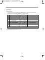
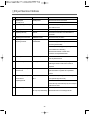
❑ Electric Parts List - Gas Clothes Dryer
Part Name
Part Code
Lamp AS
3612625300
Type No
Rating
Lamp Holder: 4000 series
75W, 125V
Lamp Base: E12
15W, 125V
Main function
Power is applied to the lamp to turn up the
light in the drum when the door is opened.
Switch Door
3619047700
SPE110F-1D3
7.5A 125V / 5A 250V AC
Thermistor Fan
361AAAAC20
CWT-DEW-1C18-A
5V R40=26.065KΩ
Themistor fan senses the temperature of
R90=4.4278KΩ
exhaust air and turns on/off the heater if
the temperature is higher/lower than the
set temp.
Switch Micro
3619047500
GSM-V1622A2
125V/250V 16A N-C
Switch micro detects a loosened or broken
belt so as to block power to the motor.
Motor Dryer
36189L5D00
S58NXSDD-6989
120V 60Hz 5.9A CL.B
The motor rotates the drum to dry laundry
evenly and the fan to expel wet air.
Igniter AS
36189L5800
DC033
120V 60Hz 4.0A
When power is supplied, igniter is heated
to 980°C (1800 °F) within 30 seconds to
ignite gas.
Flame Sensor
3614825700
10RS 43828
120V 60Hz 5.75A
When heat source is detected, contact
point is opened within 12 ~ 20 seconds to
turn off igniter before gas ignition. When
heat source is extinguished, contact point
is closed within 26 ~ 40 seconds.
Thermostat
3619047610
60T21
Hi-Limit
95°C Off, 70°C On
To prevent overheating around burner
125V/25A 250V/25A
during normal operation, power line of
flame sensor is cut off when the
temperature detected reaches 95°C and
is restored when the temperature falls
below 70°C.
Thermostat
3619047810
PBR-380 N110
Cut-Out
110°C Off, -35°C On
Overheating around burner is prevented
125V/15A 250V/7.5A
under abnormal conditions, such as
of lint filter or exhaust pipe blocking
(manual restoration possible by pressing
knob after operation commences).
Valve Gas AS
3615417200
"DEGB-1011, LPG"
2.0~3.5 kPa, 120V 0.07A
LPG gas is supplied or blocked off.
Valve Gas AS
3615417300
"DEGB-1011, LNG"
1.0~3.5 kPa, 120V 0.07A
LNG gas is supplied or blocked off.
* Parts surrounded by dotted line are exclusively for gas dryer. Other parts are common parts for electric/ gas dryer.
50
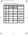
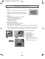
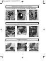
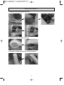
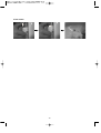
Thermostat Fan
Part Code : 3619047900
1. Function
• This is a bimetal-type switch which protects the clothes from damage by
overheating.
• If the exaust air is too hot, this thermostat stops the motor and after the air is
cooled down, it restarts the motor.
2. Specification
• A bimetal thermostat with the terminals normally connected
• Electric rating : 15A at 125V
• Opening temperature : 85±5°C, Closing temperature : 70±5°C
• Type name : PW-3N
3. Checking method of mal-function
• If temperatures are normal, the terminals of this part are connected to each other.
• Put the round metal part into boiling water and check if the resistance between the terminals drops to
0.3 or below.
• Put the same part into cold water and check if the terminals are opened.
• If the terminals do not react as mentioned above, replace them.
4. Procedure of replacement
1 Plate Top remove
2 Panel F Ass'y remove
3 Cabinet Front Ass'y remove
4 Frame Upper remove
5 Drum Ass'y remove
Thermostat Fan
6 check the position of the part
7 Remove the wires and screws to disassemble the part.
8 Assemble the parts in reverse order.
51
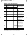
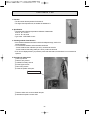
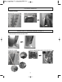
Thermostat Cut-Out
Part Code : 3619047800
1. Function
• This is a bimetal-type switch which protects the heater from overheating.
• If the heater is overheated abnormally, this thermostat cuts off the heater
PERMANENTLY.
• Note that this thermostat is NON-RESETTABLE; if it is opened, it should be
replaced by new one.
2. Specification
• A bimetal thermostat with the terminals normally connected
• Electric rating : 25A at 125V
• Opening temperature : 140±5°C, Closing temperature : -35°C
• Type name : PW-3N
3. Checking method of mal-function
• If temperatures are normal, the switch is not opened.
• If the switch is opened (the resistance between the terminals is 100M or higher), replace it.
• Note) The switch is resettable under -35°C but the temperature can not be achieved in a household
refrigerator.
4. Procedure of replacement
1 Remove the back cover.
2 Check the position of the part.
Thermostat Cut-out
3 Remove the wires and screws to disassemble the part.
4 Assemble the parts in reverse order.
52
Thermostat Hi-Limit
Part Code : 3619047600
1. Function
• This is a bimetal-type switch which controls the heater operation.
• If the heater is too hot, this thermostat stops the heater and after the heater
is cooled down, it restarts the heater.
2. Specification
• A bimetal thermostat with the terminals normally connected
• Electric rating : 25A at 125V
• Opening temperature : 125±4°C, Closing temperature : 94±5.5°C
• Type name : 60T
3. Checking method of mal-function
• After 3 minutes of the air dry program, the terminals of this part are connected to each other.
• Press the power and start buttons while you push the door switch after opening the door.
• Check if the heater operates after the drum starts rotating.
(To do this, check if the heater turns red or feel warm air in the drum with your hands).
• If the heater operates, run the air dry program for more than 3 minutes after closing the door.
• Switch off the power and measure the resistance between the terminals. If the value is greater than 1,
replace the switch.
4. Procedure of replacement
1 Remove the back cover.
2 Check the position of the part
Thermostat Control
3 Remove the wires and screws to disassemble the part.
4 Assemble the parts in reverse order.
53
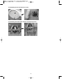
Lamp Assembly
Part Code : 3612625300
1. Function
• This is a lamp assembled with its bracket and window.
• If the user opens the door, the door switch gives electric power to this
lamp and it turns on.
2. Specification
• An assembly of an electric lamp, bracket and window.
• Power consumption : 15W at 120V
• Type name : TGE-12015L
3. Checking method of mal-function
• The lamp is turned on when the door is opened.
Lamp
Braket
Window
• Run the dryer by pressing the power and start buttons.
• As the drum begins rotating, check if the lamp is turned on after opening the door.
Cf) If the drum does not rotate, check the door switch, belt switch, and thermostat fan.
• If the lamp is still off, remove panel f ass’y and check if 120v voltage is applied to the lamp.
• If the lamp is off even though the 120v voltage is being applied, replace the lamp.
Cf) If 120v voltage is not applied to the lamp, replace the door switch.
4. Procedure of replacement
1 Plate Top remove
2 Panel F Ass'y remove
3 Cabinet Front Ass'y remove
4 Remove the wires and screws to disassemble the part.
5 Assemble the parts in reverse order.
<$$=%#!*;%!=8'%:=!>'$+!
*;%!1#=1.%!$>!*;%!.'0+?
Lamp Ass'y
7 Remove the wires and screws to disassemble the part.
8 Assemble the parts in reverse order.
54
Switch Door
Part Code : 3619047700
1. Function
• This is a switch that checks whether the door is open or closed.
• If the user opens the door, this switch disconnects power supply to the
motor and turns the lamp on.
• If the user closes the door, this switch connects power supply to the
motor and turns the lamp off.
2. Specification
• A push switch - stroke 70mm, tree terminals
pushed-down : COM and NO are connected (NO are connected to motor)
free state : COM and NC are connected (NC are connected to door lamp)
• Electric rating : 7.5A 125V
• Type name : SPE110F
3. Checking method of mal-function
• This switch applies power to the motor when the door is closed and to the lamp when the door is
opened.
• Run the dryer by pressing the power and start buttons.
• As the drum begins rotating, check if the lamp is turned on after opening the door.
• If the drum does not rotate, check the door switch contact.
Cf) Check a belt switch and thermostat fan also for the problem.
• If the lamp is still off while the drum is running, remove panel f ass’y and check if 120v voltage is applied
to the lamp.
• If 120v voltage is not applied to the lamp, replace the door switch.
Cf) If the lamp is off even though the 120v voltage is being applied, replace the lamp.
4. Procedure of replacement
1 Plate Top remove
2 Panel F Ass'y remove
3 Cabinet Front Ass'y remove
Door Switch
4 Remove the wires. Press both ends of the switch and pull.
5 Assemble the parts in reverse order.
55
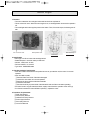
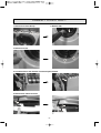
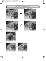
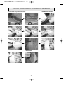
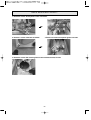
Heater Assembly
Part Code : 3612802500
1. Function
• This is an assembly that heats air in the drum.
• Two 2500-W upper/lower heaters are connected in a parallel circuit,
producing 5,000W
• According to the program set, either one or two heaters operate.
2. Specification
• Two heaters with the same specification are connected in a parallel circuit.
• Single heater: Ni/Cr wire 0.8mm, 6 coil turns,
Heater A (upper)
2500W rated output based on 240V
• Electric rating : 240V 5000W (2500W x 2)
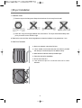
• Type name : TGE-24050H
Heater B (lower)
3. Checking method of mal-function
• Check if the resistance of both ends is 17.3~25.9.
(For your safety and accurate measurement, check the resistance after running ‘Dry Air’ program for
more than 5 minutes).
• If the resistance is beyond the range, replace the heater.
• Do not use a heater of which the coils have too narrow width or drooped excessively.
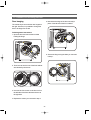
4. Procedure of replacement
1 Remove the cover back.
2 Remove the wires of duct inlet ass’y and screws to disassemble the part.
Loosen the 4 screws as indicated
with a circle.
3 Remove all screws of duct inlet ass’y and detach the
duct inlet front.
4 Remove the heater and install a new one. Heater Ass'y
5 Assemble the parts in reverse order.
56
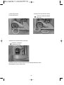
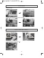
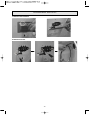
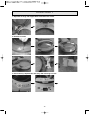
Belt Switch (Switch Micro)
Part Code : 3619047500
1. Function
• The switch cuts the power supply to the motor when a belt is
broken.
• The switch is on when the belt has adequate tension but off when
the belt gets loosened or broken, blocking the power supply to the
motor.
2. Specification
• Micro switch with two terminals, NC (normally closed) type
free state : COM and NO are connected
pushed down : COM and NC are disconnected
• Electric rating : 250V 16A 1/2HP
• Type name : GSM-V1622A2
3. Checking method of mal-function
• The switch is in normal operation if the drum rotates.
• Start the unit and check if the drum operates.
• If the drum fails to rotate, press the power button to stop the dryer and then again to check if the motor
runs.
• If you can not hear the running of the motor, disassemble the dryer and check the belt switch contact.
• Press the lid of the belt switch. If the resistance between contacts is greater than 1, replace the belt.
4. Procedure of replacement
Normal belt - switch lid free
Damaged belt - switch lid pressed by the spring
Belt Switch
57
1 Plate Top remove
2 Panel F Ass'y remove
3 Cabinet Front Ass'y remove
4 Frame Upper remove
5 Drum Ass'y remove
6 Check the position of the part.
7 Remove wires and 2 screws that fix the
switch.
8 Assemble the parts in reverse order.
Thermistor Fan
Part Code : 361AAAAC20
1. Function
• The fan senses the temperature of exhaust air.
• The higher the temperature is, the smaller the resistance is.
2. Specification
• Thermistor with following temperature-resistance characteristic.
at 90°C : R = 4.43 kΩ
at 40°C : R = 26.07 kΩ
• Type name : CWT-DWE-1C18-A
3. Checking method of mal-function
• If the resistance between terminals is within the adequate range, the fan is in
normal operation.
• You can test the resistance of the thermistor as follows.
- Put the metal rod into cold water (10~20°C): 40 within 30 seconds
- Put the metal rod into boiling water (95~100°C): 4 within 30 seconds
• If ‘H2’ error is displayed when you press the power and start button, the thermistor is not connected so
replace it.
4. Procedure of replacement
1 Plate Top remove
2 Panel F Ass'y remove
3 Cabinet Front Ass'y remove
4 Frame Upper remove
5 Drum Ass'y remove
6 Check the position of the part.
Thermistor Fan
7 Remove wires and 1 screw to detach the part.
8 Assemble the parts in reverse order.
58
Motor Dryer
Part Code : 36189L5D00
1. Function
• The motor rotates the drum using the belt as well as the fan to expel wet air.
• This is a shunt AC motor. When the motor begins to run, a centrifugal switch shorts out the operation
coil.
• The centrifugal switch also supplies power to the heater. Thus, if the motor stops, the heater goes off
also.
Fan connection axis
Belt operation axis
Belt assembly
Inner wiring
2. Specification
• Shunt type 1/3 HP AC motor with centrifugal switch
• Rotational speed : more than 1600 rpm with load
• No load : 190W, 4.9A at 120V
• Full load : 555W, 6.1A at 120V
• Type name : S58NXSDD-6989
3. Checking method of mal-function
• If the drum rotates and exhaust air is expelled as soon as you start the unit, the motor is in normal
operation.
• If the drum fails to rotate;
1 Remove Plate T and check if the belt is damaged.
2 Check if the door switch is in normal operation.
3 Remove the drum and check the thermostat fan.
4 Check the belt switch.
5 Run the unit while you press the lid of the belt switch and see if the motor starts operating.
• If a fault is found in any part mentioned above, replace it and check the operation of the motor (5).
• If no fault is found but the motor still fails to operate5, replace the motor.
4. Procedure of replacement
1 Plate Top Remove
2 Panel F Ass'y Remove
3 Cabinet Front Ass'y Remove
4 Frame Upper Remove
5 Drum Ass'y Remove
6 Cover Fan Remove
59
5 Drum Ass'y remove
6 Cover Fan remove
7 Remove the cover fan and 3 screws.
Loosen the 3 screws as indicated
with a circle.
8 Remove the 4 screws and the motor ass’y.
Loosen the 3 screws as
indicated with a circle.
9 Remove wires and 2 clamps that fix the motor bearing to detach the motor.
0 Assemble the parts in reverse order.
60
Igniter As
Part Code : 36189L5800
1. Function
• Igniter for fuel gas ignition.
• Igniter heats up quickly when power is supplied. If fuel gas is
injected to the surrounding area of igniter, gas is ignited by
the heat of igniter.
2. Specification
• A heating element made by Silicon Carbide
• Electric rating : 120V 4.0A (steady-state current)
• Temperature rating : reaches 1800"within 30 seconds
• Type name : DC033
3. Checking method of mal-function
• Igniter is heated up to very high temperature. Therefore, extreme caution is required in handling to
prevent burn.
• At room temperature, resistance between two terminals of this part is generally between 300~400Ω
• Part is defective if resistance between terminals measured after separating cable connected to igniter is
250Ωor less.
• Part is defective if cracks are found when separating igniter and closely observing the surface.
• In two of the above conditions, igniter is defective, therefore needs to be replaced.
Laniter As
4. Procedure of replacement
1 Plate Top Remove
2 Panel F Ass'y Remove
3 Cabinet Front Ass'y Remove
4 Frame Upper Remove
5 Drum Ass'y Remove
6 Cover Fan Remove
7 Separate the connected cable and unfasten 1 screw
to separate parts.
8 Assemble part in reverse order of the above
procedures.
61
Flame Sensor
Part Code : 3614825700
1. Function
• Sensor flame is the switch that operates by detecting fuel gas
ignition or heating of igniter.
• Contact point is opened when sufficient radiant heat is detected
through the transparent window at the bottom of sensor.
• When igniter is sufficiently heated, this is detected to turn off igniter.
Then, state of internal contact point is continuously maintained to
be off by combustion heat of the ignited gas.
• When gas supply is cut off, state of internal contact point becomes 'on' again so that to enable re-ignition
by igniter.
2. Specification
• A bi-metal switch that is operated by radiation heat
• Electric rating : 120V 5.75A
• Operation : opened within 12~20 seconds after suitable radiation starts heating it.
closed within 26~30 seconds after radiation heat disappears.
• Type name : 10RS
3. Checking method of mal-function
• At room temperature, there is the state of short between two terminals of this part.
• Part is defective if resistance between terminals measured after separating cables
connected to sensor flame is 1Ωor more.
• Part is defective if the area between terminals is not opened 30 seconds after
separating sensor flame and holding flame of lighter near transparent window at the bottom
(less than 1cm).
- Flame of lighter must be as long as the length of transparent window and
the flame must not be in direct contact with transparent window.
- Transparent window of sensor flame must be kept clean at all times to
enable normal operation.
• Part is detective if resistance between terminals is not 0.3Ωor less within 50
seconds after removing the flame of lighter.
• In three of the above conditions, sensor flame is detective, therefore needs to be replaced.
4. Procedure of replacement
1 Remove plate top.
Sensor Flame
2 Remove panel F ass'y.
3 Remove cabinet front ass'y.
4 Remove frame upper.
5 Remove drum ass'y.
6 Check attachment position.
7 Separate the connected cable and unfasten 1 screw to
separate parts.
8 Assemble part in reverse order of the above procedures.
62
Laniter As
Thermostat Hi-Limit
Part Code : 3619047610
1. Function
• This is a bimetal-type switch which stops the burner overheating.
• If the burner is too hot, this thermostat shuts off the gas valves and after the
burner is cooled down, it allows the gas valves to operate.
2. Specification
• A bimetal thermostat with the terminals normally connected
• Electric rating : 25A at 125V
• Opening temperature : 95°C, Closing temperature : 70°C
• Type name : 60T21
3. Checking method of mal-function
• After operating air dry program for 5 minutes or longer, the terminal status of this part must be short.
• Part is defective and to be replaced if resistance between terminals measured after separating cables
connected to sensor flame is 1Ωor more.
4. Procedure of replacement
1 Remove plate top.
2 Remove panel F ass'y.
3 Remove cabinet front ass'y.
4 Remove frame upper.
5 Remove drum ass'y.
6 Check attachment position.
7 Separate the connected cable and unfasten 2
screws to separate parts.
8 Assemble part in reverse order of the above
procedures.
Thermostat-Limit
63
Thermostat Cut-Out
Part Code : 3619047810
1. Function
• This is a bimetal-type switch which protects the burner from overheating.
• If the burner is overheated abnormally, this thermostat cuts off the gas
valves PERMANENTLY.
• Note that this thermostat is MANUALLY-RESETTABLE; by pressing the
knob on the top, this part is returned to reusable state.
2. Specification
• A bimetal thermostat with the terminals normally connected
• Electric rating : 15A at 125V
• Opening temperature : 110°æ5°C, Closing temperature : -35°C
• Type name : PBR-380
3. Checking method of mal-function
• In normal operation status, the area between terminals must not be opened.
• If it is opened (resistance between terminals 100M ߟ or more), press knob at the top two or three
times to restore.
• If resistance between terminals is 1ߟ or more after manual restoration, replace part as it is defective.
(This part is restored to be reused if placed at temperature of -35°C or lower. However, this is an
extremely low temperature that cannot be reached with general refrigerator for household use.
Therefore, it is effective to press knob for restoration.)
4. Procedure of replacement
1 Remove plate top.
2 Remove panel F ass'y.
3 Remove cabinet front ass'y.
4 Remove frame upper.
5 Remove drum ass'y.
6 Remove mixing venturi AS.
6Mixing Venturi AS
7Funnel
8Thermostat Cut-Out
7 Unfasten 2 screws fixing funnel in position and separate all of the connected cables. Then, carefully
take out funnel.
8 Remove 2 screws and separate thermostat cut-out.
9 Assemble part in reverse order of the above procedures.
64
Valve Gas As
Part Code : 3615417200, -7300
1. Function
• Valve gas AS supplies or blocks off fuel gas.
• 2 valves are horizontally connected to safely block off gas leakage.
• Each valve is solenoid value. Gas passed through this valve is injected after
being stabilized to the prescribed output pressure in regulator.
• Therefore, even if input pressure of supplied gas changes, the prescribed
amount of gas is stably supplied.
2. Specification
Part Code
LPG
LNG
Type Name
Electric Rating
DEGB-1011
120V 60Hz 0.07A
3615417200
3615417300
Input pressure Output pressure
2.0~3.5 kPa
2.24 kPa
1.0~3.5 kPa
0.87 kPa
"power input - rectified 120Vdc
3. Checking method of mal-function
• To check or replace valve gas AS, gas pipe must be locked in advance for safety.
• At room temperature, resistance between two terminals of each valve is 2.4~2.7 kΩ.
• Part is defective if resistance between terminal measured after separating cables connected to valve
gas AS is 2.0Ωor less or 3.0 kΩor more.
4. Procedure of replacement
1 Remove plate top.
2 Remove panel F ass'y.
3 Remove cabinet front ass'y.
4 Remove frame upper.
5 Remove drum ass'y.
6 Remove 2 screws fixing pipe AS in position.
7 Remove 4 screws fixing pipe AS on to guide bunner.
8 Separate the connected cable and unfasten 1 screw to separate parts.
9 Assemble part in reverse order of the above procedures..
6Pipe AS
7Guide Buner
65
❑ DISMANTLING METHOD PER DRYER ASS'Y
PANEL FRONT ASS’Y
1.Remove left cap and unfasten screw.
2. Separate panel front. (CAUTION : Internal hook damage attention)
PLATE TOP ASS'Y
2. Remove 4 screws at the back.
1. Remove 3 screws at the front.
3. Separate plate top by pushing it at the front part in the direction of arrow.
66
CABINET FRONT ASS'Y
2. Remove filter.
1. Remove 4 screws at the top.
3. Remove 3 screws.
4. Lift cabinet front in the direction of arrow and pull it forward.
5. Remove door switch connector.
67
FRAME UPPER
1. Remove 2 screws from left and right in front
part.
2. Remove 2 screws from left and right at the
top.
3. Separate frame upper after removing harness at the back.
SEPARATION OF LAMP,PCB MAIN CONNECTOR
1. Separate lamp connector.
2. Separate main PCB connector.
3. Separate humidity sensor connector.
68
PCB MAIN
1. Remove 2 screws.
3. Separate frame upper after removing harness at the back.
DUCT OUTLET ASS'Y
1. Remove 2 left and right screws.
2.Remove 1 screw.
3. Remove duct outlet F in the direction of
1
2
69
SUPPORT DRUM FRONT ASS'Y
1. Push up idler in the direction of arrow to remove belt. Then, separate belt and remove drum.
DRUM ASS'Y
1. Remove 1 rear screw and separate pipe exhaust in the direction of arrow.
PIPE EXHAUST
1. Remove 1 rear screw and separate pipe exhaust in the direction of arrow.
70
COVER BACK
1. Remove 10 screws.
2
1
SUPPORT DRUM REAR ASS'Y
1. Remove heater terminal connection cable.
2. Remove 7 screws.
3. Remove support drum rear ass'y in the direction of
71
MOTOR CONNECTOR
1. Separation of temperature sensor: Separate connector.
2. Separation of thermostat fan: Separate connector.
3. Separation of micro switch:
4. Separation of motor connector.
72
Remove 1 screw.
Remove 2 screws.
TERMINAL BLOCK
1. Remove cover terminal.
2. Remove 3 screws.
73
MOTOR ASS'Y
1. Remove 6 screws and separate motor ass'y.
2. Separation of cover fan: Remove 2 screws.
3. Separation of impeller fan: Fix motor axis and separate fan.
74
4. Dismantling of case fan: Remove 3 screws.
5. Dismantling of bracket motor: Remove 2 clamp motors each.
75
HEATER ASS'Y
1. Remove 4 screws.
2. Unfold 4 side fixing parts.
3.Remove thermostat 2 screws.
LAMP ASS'Y
1. Remove 1 screw.
76
4.Remove 13 screws.
FILTER DUST ASS'Y / HUMIDTY SENSOR
1. Filter dust ass'y: Remove 2 screws.
2. H/S: Remove connector.
3. Remove H/S.
77
DOOR ASS'Y
1. Separation of hinge and support drum front: Remove 2 screws.
2. Remove 13 screws.
3. Door lock ass'y: Separate door lock ass'y after removing 2 screws.
78
4. Door switch
79
GAS BURNER ASS'Y
1. Remove 6 screws. And separate 2 valve connectors.
2. Remove 1 screws at the back of cabinet.
3. Remove 2 screws and separate igniter connecter.
3. Remove 2 screws after removing harness at thermostat Cut-Out, Hi-Limit.
80
81
ABOUT THIS MANUAL
@ABACD!EFGHIA@GJ!ADE?
KL MNO PQR
STU VWXY Z[
\
]
a!C!b!G!<
k
^Q_ `
H=9$!I<cde!f!g!f!EH!f!hh<iB@Ej
l
em
nm
o
p
qm
Zm
dm
r
s
w
x
u
t
v
aGaC
•‚?•Z?q•ƒ„wn•JneJnqJnZJndJnSJncJn‚JqeJqnJqqJS‚…‚nJ†ƒinS,j
•‚?•d?•cƒ†eJ‡mJqJZJeˆJnnJnZJqdJd•JdeJdZJdSJSZJ†nƒien,j
•‚?•‚?enƒ†eJ‡mJZJdJˆ…e‚JnˆJqnJdSJdcJcSJccJ‚•in•,j
•‚?•‚?eqƒecie,j
•‚?•‚?eZƒeSie,j
•‚?•ˆ?nqƒeˆie,j
•‚?ee?ec€ˆ,J!e•,J!ee,J!en,J!eq,J!eZ,J!ed,J!eS,J!ec,J!e‚,J!eˆ,J
n•,J!ne,!lpƒ!„w eq,
•‚?ee?eˆ€ed,J!ne,!lpƒ!„w n,
•‚?ee?nZ€e‚,!lpƒ!„w e,
•‚?en?•Z€e•,!lpƒ!„w e,
yz{
@ABACD \ ]
| } l
IG<~ cq•€•SS•!•Hh~ cq•€qc‚‚